

Page 1

1 | Page
* Installer: Leave this manual with the New Owner *
Also be sure to check the grill box completely for ALL parts including
the rotisserie spit rod (if applicable)
Renaissance Cooking Systems
Owner’s Manual
For Outdoor Use Only
America's Best Value in Outdoor Kitchen Equipment
Installation, Operation, Mainte nance
Instructions & Parts List
RJC26A, RJC32A, RJC32AL,
Models:
T
hese grills are tested a nd cert i f i ed t o the ANSI-Z21.58/CSA 1.6.standards.
RJC40A, RJC40AL, RON30A,
RON38A & RON42A
This owner’s manual was updated March 2018
For the latest news, recipes and cooking tips for your new
Renaissance Cooking Systems grill, check out www.RCSGasGrills.com
Page 2
2 | Page
Contents Page
For Your Safety
3-7
Safety Rules
8
Clearance to Combusti bl es
5 & 12
BTU Ratings
10
Gas Barbecue Specifications
10
LP Tank Requirement
11-12
Installation Location/Cut Outs
12-14
Gas Connections
15-16
Electrical/Wire Diagram
Burner Adjustment s
Lighting Instructions
Operation
First Time Operation
Cleaning and Maintenance
Gas Conversion /Trouble Shooting
Troubleshooting
Parts Diagram
Warranty
16-18
19-20
20
21
22
23
24-26
26
27-32
33
Message to the Proud Ow ner
Congratulations on the purchase of this high quality, high
performance grill.
Read thi
about how to install, operate and mai ntain for optimum
performance and longevity.
Keep t
For any as
Number and Serial Number of the grill which is located on the
right hand or left hand side of the control panel depending on
model:
Premier Series: RJC26A, RJC32A, RJC32AL, RJC40A & RJC40AL – left side
Cutlass Pro Series: RON30a, RON38a & RON42a – right side
s manual carefully to understand all the i nstructions
his manual in a safe place for future reference.
sistance, contact us. Mak e sure to provide the Model
Thank you for purchasing your
years of grilling pleasure.
new RCS grill. We wish you
Page 3
3 | Page
Safety and Installation Instructions
GRILL INSTALLATION
This gas grill must be installed in accordance with all local codes.
If installation is planned in an area with no local codes, the gas grill must be
installed in accordance with the National Fuel Gas Code ANSI Z223.1 and
storage and handling of liquefied petroleum gases, ANSI/NFPA 58 or CSA
B149.1 natural gas and propane installation code.
WARNING: Improper installation, adjustment, alteration, service or
maintenance can cause injury or property damage, and void the warranty.
Read the installation, operating and maintenance instructions thoroughly
before installing or servicing this equipment.
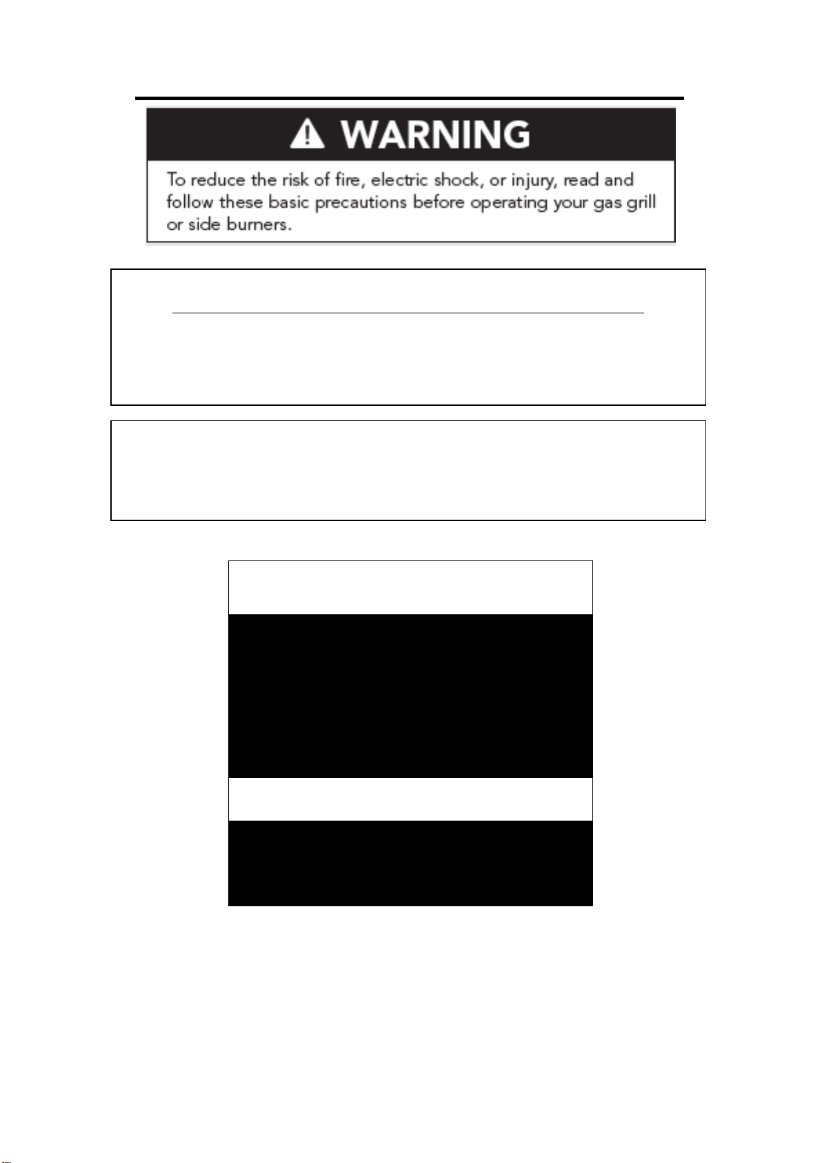
FO
R YOUR SAFETY
1. If you smell gas:
2. Shut of f gas to the appliance.
3. Extinguish any open flames.
4. Open lid.
5. If odor continues, immediately
call your gas supplier.
!!! WARNING !!!
Read the “Lighting Instructions” in
this manual, before lighting this
appliance.
Page 4

4 | Page
FOR YOUR SAFETY
The Burning of gas cooking fuel generates
cooking with gas.
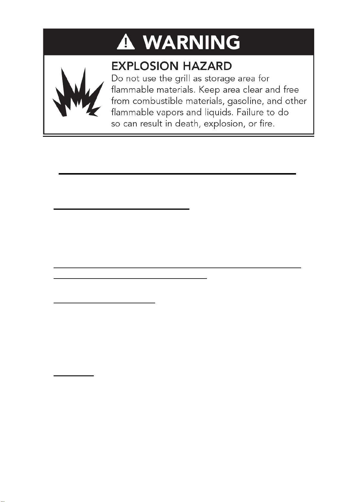
1. Do Not store or use gasoline,
caustic or other flammable vapors
and liquids in the vicinity of this
or any other appliance.
2. An LP cylinder not connected for
use shall not be stored in the vicinity
of this or any other appliance.
TESTED IN ACCORDANCE WITH ANSI
STANDARD FOR OUTDOOR COOKING
GAS APPLIANCES. THIS GRILL IS FOR
OUTDOOR USE ONLY.
Check your local building codes for the proper
method of installation. In the absence of local
codes, this unit should be installed in
accordance with the National Fuel Gas Code
No. Z223.1-CAN/CGA—B149.1, natural gas
installation co de or CAN/CGA—B149.2,
propane installation code.
CALIFORNIA PROPOSITION 65-
Some by-products which are on the list of
substances which are known by the State of
California to cause cancer or reproductive
harm. California law requires businesses to
warn customers of potential exposure to
such substances. To minimize exposure to
these substances, always operate this unit
according to the use and care manual,
ensuring you provide good ventilation when
!!! WAR NING !!!
Page 5
5 | Page
Safety and Installation Instructions
Location of your Barbecue
Most importantly, this is an outdoor appliance. Ensure your barbe cue is
positioned safely away from anything that can catch fire.
Under no circumstances is this barbecue to be used indoors. This
includes garages or any other enclosed area.
Clearance from Combustibles: Ensure your barbecue remains at a distance
of at least 24” from any combustible material such as wood, gyprock,
paper and plants. Do not store combustible, caustic materials, gasoline or
flammable liquids or vapors within 48” of the barbecue. Do not locate
under unprotected combustible materials. Do not store ANY types of
chemicals in a cabinet near the grill or any stainless components, doors,
drawers, etc.
Wind Guard: WARNING! Y our RCS grill should NOT be installed with the back of the grill
facing frequent, prevai ling winds like a large body of w ater or open space unless there is a
substantial back splash or some way of blocking the wind. In some rare occur rences, when
there is a strong wind present, it c an cause heat that is norm ally exhausted thr ough the rear
ports to be forced back into the grill and may cause overheating of the control panel and
controls. Damage caused by this type of installation is not covered by warranty. If you are
experiencing this problem , please contact us to order a wind guard which may or may not
solve your problem but m ay be a possible alternat ive to changing the locat ion of the grill if it
has been installed with the rear of the grill facing the prevailing winds.
Page 6
6 | Page
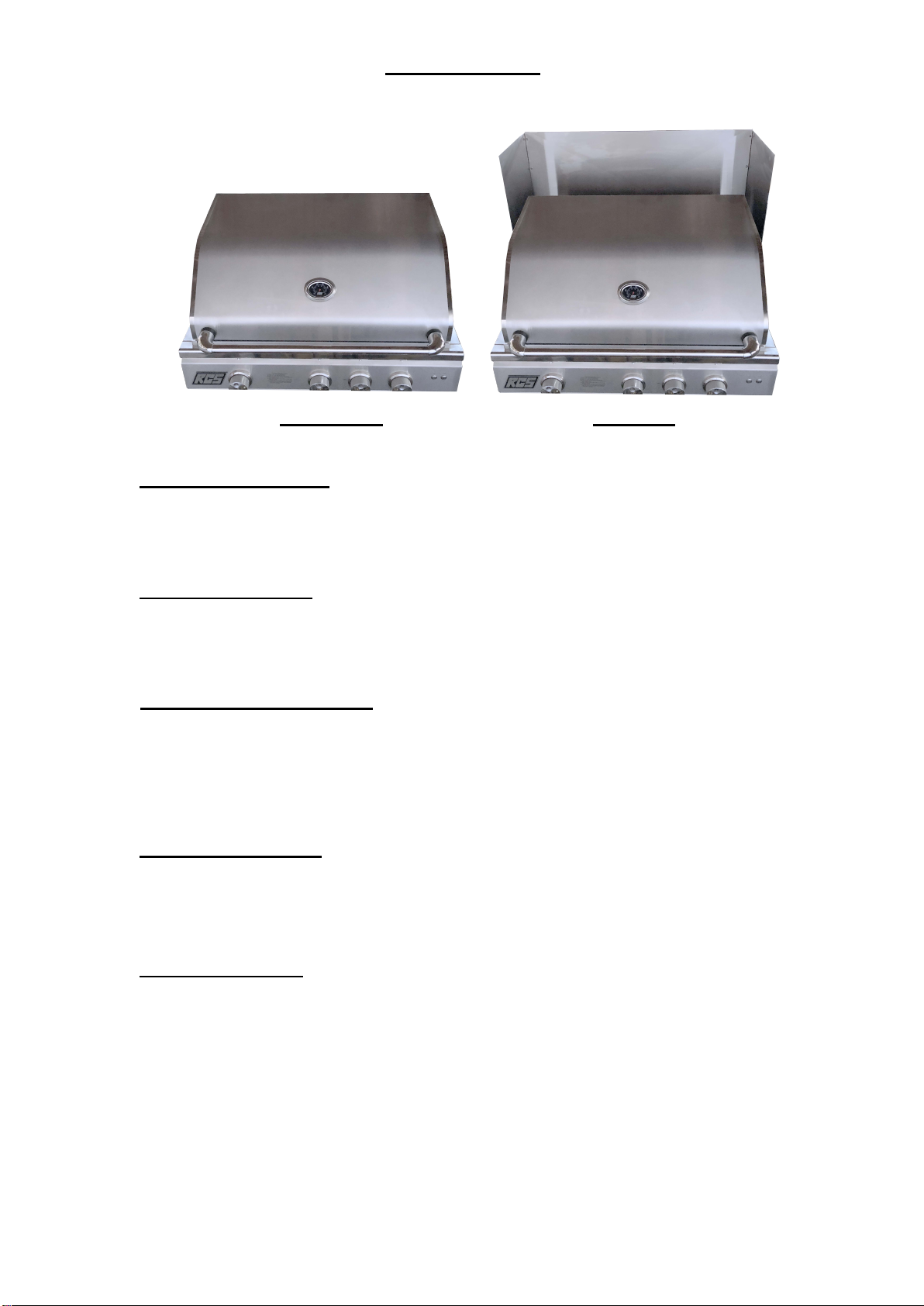
Model/Part Number
RWGM - RJC26A/RJC32A/RON30A RWGL - RJC40A/RON38A/RON42A
BEFORE AFTER
Adequate Ventilation: Ensure there is adequate ventilation for both the
barbecue and cylinder. This is required for proper combustion and to prevent
gas build up.
Firm Level Surface: Use your barbecue only on a firm level surface. This
barbecue is not designed for recreational vehicles, and shall not be installed
on a boat or any marine craft.
Protection from Weather: Keep the barbecue protected from adverse
weather, including rain and high winds. Covers are available that have
been specially designed for this range of barbecues. Allow clear access to
the entire gas supply hose and regulator.
Maintenance A ccess: When your barbecue is installed, you should be a bl e to
access the gas supply line including the gas piping or hose, gas regulator, gas
cylinder and any shut off valves. Do not grout in barbecue grill.
Partial Enclosures: Many backyards have areas that are partially closed off,
such as balconies and pergolas. In some cases, it is hard to decide whether
these partially encl osed ar eas sh ould b e clas si fied as i ndoor areas, par ticul arl y
in terms of permanent (non-closable) ventilation. The gas safety authorities
have agreed on the definition of partial enclos ures bel ow (See page 7).
Page 7
7 | Page
Page 8

8 | Page
Safety Rules
1. It is important to follow these rules to avoid fire hazard, property damage or bodily injury
from impr oper installation or usage of the grill. For safety, READ all rules carefully and
check local codes.
2. It is prohibited to install the grill in recreational vehicles/mobile homes, trailers, boats, etc.
The grill is for outdoor installation and use only.
3. Ensure proper installation by f ollowing the installation instructions. Make sure to know
where the gas supply shut-off valve is locate d. It should always be readil y and easily
accessible.
4. Check all gas line joints & connections for gas leak with soap water solution. Never
check gas leak with an open flame.
5. Do not attempt to repair or replace any part of the grill unless specifically
recommended in this m anual. All other services should be perf ormed by a qualifie
s
ervice tec h nic i an.
6. Do not place clothing or other flammable material on or near the appliance. Do not
wear loose-fitting clothes or long sleeves while using the grill as some fabrics may
hi
ghly flammable.
d
be
7. Children should be carefully supervised when they are in the vicinity of the grill. Do not
allow them to get close to the gr il l wh il e in u se. It ems of i nt er est to ch il dr en sho u ld n ot
be stored in or around the grill in the cabinet or in the masonry enclosure. Portions of the
grill can be extremely hot while in use and can cause severe burns.
8. Protect your hand with a glove or mitt when opening and operating the grill. Open grill lid
lowly to allow heat and smoke to escape before fully opening.
s
9. Never use aluminum foil to line the crumb pan or grill racks. This can alter airflow for
proper combustion and also build up heat in the control area causing the knobs and
igniters to melt and void your grill warranty.
10. Grease is highly flammable. Allow hot grease to cool down before attempting to
handle it. Clean grease tray often so that grease does not accu mulate and st ay i n it which
may cause a fire.
11. Do not operate the grill in a windy area. For windy areas we recommend the RCS Wind
Guard. (see page 5-6)
12. Do not obstruct the flow of air into the front of the grill or any vent ar eas.
13. The grill should be installed facing towards the prevailing winds to help eliminate drafts
from behind which can heat up and dam age the control panel, controls, electr onics, and
voids warranty. We have wind guards available to help protect against the wind.
(see page 5-6)
14. Always keep your grill CLEAN to eliminate grease fires which are dangerous.
Page 9

9 | Page
Gas Connections
Check gas type – use only the type of gas indicated in the rating plate.
Do NOT c
regulator(s) that are available from RCS.
afe and satisfactory operation depends to a great extent on the proper installation of the
S
appliance. The installation must comply with the local codes, or in the absence of local codes, with
either the National Fuel Gas Code, ANSI Z223.1 or CAN/CGA – B149.1 or 149.2.
Installer supplied manual gas shut-off valve must be installed in an easily accessible location in the
gas supply line ahead of the pressure regulator (4”W.C.).
The outdoor cooking gas appliance and its individual shut-off valve must be disconnected from the
gas supply
Psi (3.5kPa). Over-pressure will cause the valves to fail and void the warranty!
T
he supply line must be sized and installed to provide a sufficient supply of gas to meet the
maximum demand of the grill without undue loss of pressure. The sealant used on the threaded
joints of the gas pipe must be a type resistant to the action of LP gases.
onnect an unregulated gas source to the appliance. You MUST use the
piping system during any pressure testing of the system at test pressures in excess of 1/2
Page 10
10 | Page
GAS BARBECUE SPECIFICATIONS
Grill Model
Main Burners
Rear Burners
Total BTU’s
12,000
-
36,000
12,000
12,000
60,000
12,000
12,000
72,000
15,000
12,500
57,500
15,000
12,500
72,500
15,000
12,500
72,500
BURNER INPUT RATING
RJC26A
RJC32A / RJC32AL
RJC40A / RJC40AL
RON30A
RON38A
RON42A
Natural Gas Connection:
Appliance pressure 4” W.C.
Inlet pressure 5” – 14” W.C.
Check with your local gas utility company or with local codes before installi ng gas lines.
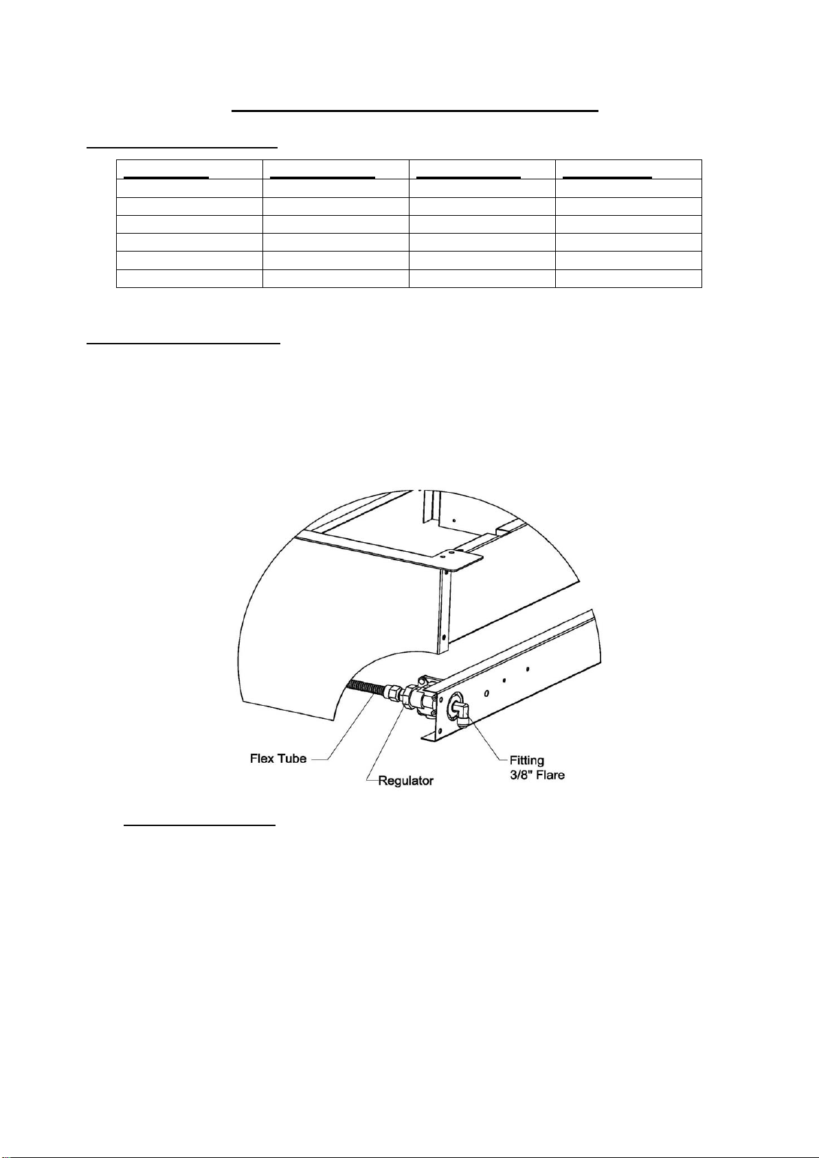
urchase a standard 20 LB. LP tank with QCC – 1
P
and regulator like the RCS RONHK. (Available From Your RCS Dealer)
Assemble pipe/hose assembly as shown (not included).
LP Gas Connection
Appliance pressure 10” W.C.
Inlet pressure 11” – 14” W.C.
fitting, and an approved hose
Page 11

11 | Page
To connect, insert the regulator inlet into the tank valve and turn the black coupler
The RONHK hose kit is shown here.
clockwise until the coupler tightens up. DO NOT OVER TIGHTEN THE COUPLER.
After completi on o f assembly, make sur e all a ppli ance c ontrol v alv es ar e OFF then turn the
tank supply valve on and then turn the control valves on the grill to the ‘HI/IGN’ position
for 10 seconds to purge the line of air.
Inspect the hose be for e each use of the appliance. If it i s evident there is abrasion or wear,
or the hose is cut, it must be replaced prior to the appliance being put into operation. The
replacement hose assembly shall be that specified by the manufacturer.
To disconnect, turn the tank valve off. Hold the coupler sleeve and turn counter clockwise.
The inlet line will be disengaged.
If the appliance is not in use, the gas must be turned off at the supply cylinder. Cylinder
must be stored outdoors out of reach of children and must not be stored in a building,
garage or any other enclosed ar ea.
A dented, rusty, outdated or damaged propane cylinder must be replaced immediately.
Check for leaks with a soapy water soluti on every time the cylinder is
replaced or reconnected. All leaks must be corrected immediately.
Never use an open flame to check for leaks.
LP Tank Requirements:
The L.P. gas cylinder must be constructed and marked in accordance with the
specifications f or L.P. gas cylinders of the U.S. Department of Transportation (DOT) and
designed for use with a QCC-1 quick disconnect system only.
The cylinder must be provided with a shut-off valve terminating in an L.P. gas supply
cylinder valve outlet specified, as applicable, for connection Number QCC-1.
The cylinder must be provided with a listed overfilling prevention device. The pressure
Page 12

12 | Page
regulator must be used. Replacement of pressure regulators and hose assemblies can be
purchased from authorized dealers.
The cylinder supply system must be arranged for vapor withdrawal. Make sure the LP
cylinder has a collar to protect the cylinder valve. Do not store a spare LP gas cylinder
under on near this appliance.
(a) Never fill the cylinder beyond 80 percent full.
(b) If the information in (a) and (b) are not strictly followed, a death-causing fire or
serious injury may occur.
Installation Location for All Models
Choose a location where the flow of air on the front of the grill is not obstructed.
Due to high temperatures, place the grill out of traffic and keep away from clothing,
furniture, or any combustible materials. Keep the gas line connection as short as
possible. Do not install in recreational vehicles/mobile homes, trailers, boats, etc.
Clearances
Combustible Construction
Minimum horizontal clearance from sides and back of the unit to adjacent vertical
combustible construction extending above top of unit, 24 inches from side and 15
inches from back. Do not locate under any overhead combustible construction. If
construction is built out of a combustible ma terial, you must use a insulated
liner jacket from RCS.
Non-Combustible Construction
Sides of the grill can be 0” from non-combustible wall, below the cooking surface.
Wind Guard: WARNING! Your RCS grill should NOT be installed with the back of the grill
facing frequent, prevai ling winds like a large body of w ater or open space unless there is a
substantial back splash or some way of blocking the wind. In some rare occur rences, when
there is a strong wind present, it c an cause heat that is norm ally exhausted thr ough the rear
ports to be forced back into the grill and may cause overheating of the control panel and
controls. Damage caused by this type of installation is not covered by warranty. If you are
experiencing this problem , please contact us to order a wind guard which may or may not
Page 13

13 | Page
solve your problem but m ay be a possible alternat ive to changing the loc ation of the grill if it
has been installed with the rear of the grill facing the prevailing winds.
Model/Part Number
RWGM - RJC26A/RJC32A/RON30A RWGL - RJC40A/RON38A/RON42A
BEFORE AFTER
Built-in Installation
For non-combustible cabinet enclosure installation only. Follow the cut-out dimensions
as shown. ALL outdoor kitchen cabinets MUST include ventilation. We recommend
12 square inches of opening for each (running) 4 feet of counter top. See Item # R VNT1
for approved vents. In the event of an inst all ation in a combusti ble (wooden) cabinet, you
must use an insulated jacket available from RCS.
Page 14

14 | Page
Model
“A” Width
“B” Depth
“C” Height
RJC26A
23 1/2”
21”
8 ¼”
30 5/8”
21”
8 ¼”
37 ¾”
21”
8 ¼”
33”
20”
11”
41”
20”
11”
45”
20”
11”
Model
Lid Clearance
25”
25”
25”
23”
23”
23”
RJC32A /RJC32AL
RJC40A / RJC40AL
RON30A
RON38A
RON42A
RJC26A
RJC32A / RJC32AL
RJC40A / RJC40Al
RON30A
RON38A
RON42A
Page 15

15 | Page
Page 16

16 | Page
If adding a side burner to your connection:
Electrical
Electrical outlet for Rotisserie motor must be installed to the left side of the grill.
The outdoor cooking gas appliance, when installed, must be electrically grounded in
accordance with local codes or, in the absence of local codes, with the National
Electrical Code, ANSI/NFPA 70, or the Canadian Electrical Code, CSA C22.1.
Keep any electrical supply cord and fuel supply hose away from any heated surface.
On the RON30a, RON38a
and RON42a, this plug is
specially used for
connecting the optional
RDB1EL side burner.
HALOGEN LIGHT: The RJC32AL, RJC40AL, RON30A, RON38A & RON42A are
provided with a low-wattage transformer. Connect 115V power to the grill.
USE the transformer provided! Replacement light bulb is 12v, 5 watts.
Page 17

17 | Page
Electrical Wire Diagram
Page 18

Page 19

18 | Page
Leak Testing
VER USE AN OPEN FLAME TO CHECK FOR LEAKS.
NE
All gas piping and connections must be tested for leaks after installation or service. All
leaks must be corrected immediately. Remember-before exchanging an empty bottle
for a new one, make sure all control valves are in the “off” position.
With the LP regulator connected to tank and grill and the grill knobs turned to OFF. Open
the valve on the tank. Test for leaks by applyin g liquid soap so lution to all joints. Bubbles
forming indicate gas leak. Fix gas leak before continuing use.
Burner Adjustments
Every grill is thoroughly checked for proper lighting and burner flame pattern. Conditions at
the location may necessitate minor adjustment of the burner air intake, if the flames
are not steady/stable as shown in the figure.
The flame should be full length of the burner, blue and stable. The air intake (if applicable)
should be adjusted ONLY if the flame is lifting off of the ports or has noticeable
amounts of yellow in the flame.
Page 20

19 | Page
If flame is lifting, remove the front panel to access the burner front (air shutter) then turn
the air shutter clockwise reducing this intake. The screw should be loosened before
turning the air shutter.
If the flame has more yellow than blue, the air s hutter should be turned count er clockwise
allowing more air in. This will stabilize the flame. Make sure to tighten the screw after
adjustments are made.
In order to provide gas to the burner, the orifice must be inside the burner venturi
opening. Check to ensure that the burner is properly secured at the front and back.
Lighting Instructions
Before Lighting:
Check gas line/hose for signs of wear, abrasion or cuts. If evidence of
deterioration is visible, replace the part prior to use.
If you smell gas, check for leaks. If odor continues, immediately call for service.
Keep your face and body away from the grill top when lighting.
ll Burner Lighting
Gri
1.
Open lid before lighting. Make sure all burners are in the
‘OFF’ position.
Push and turn burner knob to ‘HI/IGN’ position.
2.
The pilot flame will ignite at this point, lighting the main burner.
3.
Continue to hold the knob in until you have ignition.
4.
5.
If there is no ignition after 2-3 seconds, turn the knob back to the “OFF”
position and repeat steps 2-4.
Rotisserie Burner Lighting
1.
Open lid before lighting. Make sure all burners are in the
‘OFF’ position.
Be sure to remove the upper grid in the back of your grill PRIOR to lighting
2.
the rear burner!
Push in and hold the control knob for 5 seconds then turn the rear rotisserie control
3.
knob to the “on” position. While there, you’ll hear the igniter “click” This should light
the rear burner.
If you do not see the rear bur
4.
knob a little slower before the click.
ner ignite, repeat step 3 and possibly turn the control
Page 21

20 | Page
Operation
DO NOT LEAVE YOUR GRILL UNATTENDED WHILE IN OPERATION.
Grill: Grill burners are controlled individually with control knobs. After
lighting, turn the knob to HI, LO or in between as desired. Turn on as
many burners as required. The top cover may be closed during
grilling. Keep the top cover in closed position during the pre heat
period.
If you have installed an optional infra-red burner in your grill, you must leave the lid
open while the infra red burner is in use, due to the intense heat it will generate!
Rotisserie: (Not included with all models) Plug in the motor power cord to a
properly grounded receptacle.
Rotisserie cooking can be done with grill burners as well as with the
Rotisserie burner ‘ON’. KEEP THE MOTOR STORED INDOORS
WHEN NOT IS USE.
Be sure to remove the upper grid in the back of your grill PRIOR to lighting
the rear burner!
The skewers slide in from the side with the tip sliding into the motor shaft
adapter. The slot on the handle side should be on the side support
panel edge.
Use the prong s to hold t he meat . T ighte n thum bscrew on the pro ng hubs to
secure in place.
When ready, turn the switch on the motor box to the ‘ON’ position. The
skewer will rotate slowly.
Stop the motor before removing the skewer.
Page 22

21 | Page
First Time Operation
MAIN BURNERS:
Before cooking with your grill the first time, burn off any foreign matter and rid
the unit of any odors by operating the unit for about 10 minutes with all lower
burners on high.
The flame should have a bluish color to it. It may have a tint of yellow and
adjustment to the air shutters can be made to obtain a blue flame with a slight
yellow tip.
Although the grill can be operated with the hood closed, do not continually
operate the rotisserie burner with the hood closed. This will damage the grill
and void the warranty.
The grill should be preheated with the main burners on HIGH for 10-15
minutes with the hood closed. If you have an optional infrared burner, the grill
lid must remain open while the infrared burner is in use.
Temperature Settings
- Use HIGH burner setting for searing, heavy cooking, preheat and clean up.
- Use other burner settings to create temperatures to fit your personal cooking
preferences.
- Internal temperatures may
Remember-your heat indicator is just that, an INDICATOR not an actual
thermometer. ALSO-the temperature at the cooking surface is significantly
higher than what the heat indicator shows in the lid. Your RCS grill has been
designed and manufactured to provide optimum cooking temperatures across
a wide range of foods, without “cooking itself to death!”
You can cook poultry and larger cuts of m eat slowly if you turn OFF the burner
directly under the f ood and use adjacent burners to supply heat (convection
Cooking or Indirect Cooking). When cooking fattier foods, cooking with indirect
heat also greatly reduces flare-ups.
Fats and juices that drip down can cause flare-ups. Since some flare-up do
impart a distinctive and desirable flavor, taste and color to foods being grilled,
they should be carefully and reasonably encouraged. Uncontrolled or
excessive flare-ups, however, will damage your food
vary with outside temperature and wind conditions.
Page 23

22 | Page
Cleaning and Maintenance
Cleaning: Your Bar-B-Q grill works better and lasts longer if properly cleaned and
maintained. Clean the grill after each use. Turn grill off before starting to
clean. Protect you r hand with a good m itt when cleaning the hot grill. Use a
wire brush, dip in water and scrub the cooking grids to soften and loosen
food spills. The food spill s will fal l into the cru mb p an.
Do not use Aerosol cleaners on hot grill surface. Chemicals may
produce noxious fumes and may ignite on contact with the hot
surface.
Shield: Burner shields are made up of stainless steel. Occasionally, after allowing
the shields to cool down, remove and soak them in water with a mild soap
or detergent. Replace when dry.
Crumb Tra y / Grease Pan:
Empty grease pan as required to prevent overflowing. After use,
remove the pan and brush off the contents. Clean with hot water and
soap or detergent. NEVER line the pan with any type of foil!
All stainless steel parts should be cleaned with a mild soap or detergent or with a liquid
cleanser especially made for stainless steel. Never attempt to clean stainless steel
with steel wool, abrasive cloths or powders.
Maintenance
Keep outdoor cooking gas appliance area clear and free from combustible materials,
gasoline and other flammable vapors and liquids.
Do not obstruct the flow of combustion and air ventilation. Keep the ventilation
opening(s) of the cylinder enclosure free and clear from debris.
There are many different stainless steel cleaners available. Always use the mildest
cleaning procedure first, scrubbing in the direction of the grain. To touch up noticeable
scratches in the stainless steel, sand ver y lightly with dry 100 grit emery paper in the
direction of the grain.
Speck s of grease can gather on t h e surfaces of the stainless steel and bake on to the
surface and give the appearance of surface rust. Surface rust is caused by using
steel wool or steel br i st le br us hes to clean the surfaces. Never use steel wool or steel
bristle brushes on the stainless steel surfaces. It can also be caused by harsh
chemicals used in the area of the grill, like common pool chemicals or acid used to
wash down patios or decks. NEVER store chemicals of ANY kind in or near your grill!
Surface rust may also be ca used by ot her forms o f co nt ami nant s found i n t he ai r or as
a result of foreign matter introduced to the grill. For removal of most types of surface
rust, use a slightly abrasive pad (Scotch Brite is good) in conjunction with a stainless
steel cleaner. Always rub in the direction of the grain. Surface rust is not covered under
the warranty.
Page 24

23 | Page
The burners, control area, crumb pan, etc. should be kept clean at all times. During
prolonged non-use of the grill, spiders & insects can nest in areas that will adversely affect
the functioning of the grill. Check bur ner inlet s, or ifice hood ( gas inlet to burner) , igniter,
sparkers, etc. thoroughly and clean befor e use.
Fuel (Gas) Conversion Instructions for RCS grills.
This should only be performed by a licensed gas professional
xtra regulator:
E
Currently all grills are supplied with a regulator installed. W hen converting the gas
application you must also convert the regulator by removing the large nut on the front
of the regulator, pulling out the plastic orifice, flipping it over and replacing it. Tighten
the large nut and you’re ready to go. (This step does not apply to the LP hose and
regulator set, only the separate regulator that comes with the grill).
In order, the regulator must be installed and converted first in or der to achieve
the proper pressure to test the conversion steps 1-10 and back burner
conversion 1-3 below. To adjust the low flame setting if necessary, see next
page………
Unscrew and remove this brass cap
Remove brass cap. This exposes the plastic
plunger
P
replace in the hole. Large side down converts the
regulator to LP by compressing the interior
spring.
R
Note: the plunger snaps in and out of the cap.
ull off and flip over the plastic plunger and
eplace the brass cap and you are done!!!
Page 25

24 | Page
Fuel
Low flame setting
Conversion of Main Burners:
1- Determine the existing gas type. (LP or Natural gas) Changing the gas type
and orifice change out is the same for both gases.
2- You must remove all grates and burner covers to expose the main burners in
the grill.
3- On the bottom rear of each burner is a cotter pin. Remove pin.
4- Slide burner to the rear of the grill and up. Repeat for each burner.
5- Where the burner was located going through a hole in t he basin and
connecting to the valve is now evacuated space.
6- Inside the space you will find the end of the valve (front of grill), with an orifice
(brass fitting), screwed into the end of the valve stem.
7- Remove the orifice with a socket set and extension. (These are extremely
fragile when turning. Be extremely gentle when removing).
8- Replace new change out orifice, (repeat for all burners). When re-installing
orifice do not over tighten or you will strip the brass fitting. Little pressure is
needed!!!
9- Replace burners and test for proper flame height. Flame should stand at ½” to
1” on low and 1.5” to 2” on high. (to adjust the low flame setting simply light the
grill on the low setting and adjust the screw which is located under the knob on
the front of the valve as per diagram below.)
10- Replace burner covers and grates.
screw
11-If necessary , adjust the low flame setting screw located under the knobs on the
front of the valve.
N
ote: It may be necessary to adjust the air mixture on each burner after a
conversion. Typi cally LP gas requires more primary air so open the air mix ers to at
least half open. The opposite is true for natural gas. In some cases close these air
mixer adjusters completely. (n/a on cast burners)
Page 26

25 | Page
Rotisserie Burner Conversion:
1- Remove the back panel at the rear of the grill, this will expose the V shaped or
pyramid shaped brass orifice.
2- Remove the existing orifice and replace with change out orifice.
3- Replace rear panel
Trouble Shooting
Problem Solution
Burner will not light - Check gas supply to burner by manually
lighting the burners.
- See electrode for visible damage, replace if damaged.
Improper burner flame -Check burner gas inlet area for blockage
- Check orifice hoods for any clogging and clean.
- Adjust air shutter, if necess ar y.
- Check pressure if flame is too low or too high.
- Check gas supply tank (LP) if running low.
Light is not ON - Connect 115V power at rear. Turn switch ON.
- Make sure the transformer was used in installation and
your grill was NOT hooked up directly to 115 volt power
source.
- Check bulb. Replace if necessary.
- Check any GFCI plugs in line.
Page 27

26 | Page
RJC26A/RJC32A/RJC40A Enlarged View
Page 28

27 | Page
RJC26A/RJC32A/RJC40A Parts List
QTY.
RJC001P
26"-TOP HOOD
1
RJC002P
32"-TOP HOOD
1
RJC051P
40"-TOP HOOD
1 2 RJC003P
ACCESS DOOR
1
1 3 RJC004P
26"-REAR HOOD
1
RJC005P
32"-REAR HOOD
1
RJC052P
40"-REAR HOOD
1 4 RJC006P
26"-WARMING RACK
1
RJC007P
32"-WARMING RACK
1
RJC053P
40"-WARMING RACK
1 5 RJC008P
TOP GRATE
3 4 5 6 RJC009P
BRIQUETTE TRAY
3 4 5 7 RJC010P
CROSSOVER TUBE
2 3 4 8 RJC011P
BURNER 3 4
5 9 RJC012P
26"-BASIN
1
RJC013P
32"-BASIN
1
RJC054P
40"-BASIN
1
RJC015P
26"-DRIP TRAY
1
RJC016P
32"-DRIP TRAY
1
RJC055P
40"-DRIP TRAY
1
12
RJC017P
90 DEGREE FITTING
1 1 1
13
RJC018P
REGULATOR
1 1 1
RJC019P
26"-MANIFOLD
1
RJC020P
32"-MANIFOLD
1
RJC056P
40"-MANIFOLD
1
15
RJC021P
VALVE LATCH
3 5 6
RJC022P
MAIN VALVE - NATURAL GAS
3 4 5
RJC060P
MAIN VALVE - PROPANE
3 4 5
RJC023P
IR BURNER VALVE - NATURAL GAS
1 1 RJC061P
IR BURNER VALVE - PROPANE
1 1 18
RJC024P
IR BURNER FLEX TUBE
1
1
19 A
RJC025P
KNOB-MAIN VALVE
3 4 5
19 B
RJC048P
KNOB-IR BURNER VALVE
1
1
20 A
RJC026P
KNOB BEZEL-MAIN VALVE
3 4 5
20 B
RJC049P
KNOB BEZEL-IR BURNER VALVE
1 1 21
RJC027P
LOGO PLATE
1 1 1
RJC028P
26"-CONTROL PANEL
1
RJC029P
32"-CONTROL PANEL
1
RJC057P
40"-CONTROL PANEL
1
23
RJC030P
ROTISSERIE HANDLE (OPTIONAL)
1 1 24
RJC031P
SPIT COLLAR (OPTINAL)
1
1
RJC032P
32"ROTISSERIE SPIT (OPTIONAL)
1
RJC058P
40"ROTISSERIE SPIT (OPTIONAL)
1
26
RJC033P
SKEWER FORK (OPTIONAL)
1 1 27
RJC034P
THUMB SCREW (OPTIONAL)
3 3 28
RJC035P
MOTOR BRACKET (OPTIONAL)
1 1 29
RJC036P
ROTIESSERIE MOTOR (OPTIONAL)
1 1 30
RJC037P
IR BURNER IGNITION WITH WIRE
1 1 31
RJC038P
IR BURNER IGNITION HOUSE
1 1 32
RJC039P
IR BURNER ELBOW FITTING
1 1 33
RJC040P
IR BURNER JOINT NUT
1 1 34
RJC041P
IR BURNER ORIFICE
1 1 35
RJC042P
IR BURNER
1
1
RJC043P
26"-HOOD HANDLE
1
RJC044P
32"-HOOD HANDLE
1
RJC059P
40"-HOOD HANDLE
1
37
RJC045P
RUBBER STOPPER
2 2 2
38
RJC046P
TEMP GAUGE BEZEL
1 1 1
39
RJC047P
TEMP GAUGE
1 1 1
40
RJC050P
BALANCE WEIGHT
1
1
ITEM PART NO.
1
11
14
DESCRIPTION
RJC26A RJC32A RJC40A
16
17
22
25
36
Page 29

RJC32AL / RJC40AL Enlarged View
Page 30

RJC32AL/RJC40AL Parts List
ITEM PART NO. DESCRIPTION
1
2 RJC003P ACCESS DOOR 1 1
3
4
5 RJC008P TOP GRATE 4 5
6 RJC009P BRIQUETTE TRAY 4 5
7 RJC010P CROSSOVER TUBE 3 4
8 RJC011P BURNER 4 5
9
11
12 RJC017P 90 DEGREE FITTING 1 1
13 RJC018P REGULATOR 1 1
14
15 RJC021P VALVE LATCH 5 6
16
17
18 RJC024P IR BURNER FLEX TUBE 1 1
19A RJC066P KNOB-MAIN BURNER 4 5
19B RJC067P KNOB-BACK BURNER 1 1
20A RJC026P KNOB BEZEL-MAIN VALVE 4 5
20B RJC049P KNOB BEZEL-IR BURNER VALVE 1 1
21 RJC027P LOGO PLATE 1 1
22
23 RJC030P ROTISSERIE HANDLE (OPTIONAL) 1 1
24 RJC031P SPIT COLLAR (OPTINAL) 1 1
25
26 RJC033P SKEWER FORK (OPTIONAL) 1 1
27 RJC034P THUMB SCREW (OPTIONAL) 3 3
28 RJC035P MOTOR BRACKET (OPTIONAL) 1 1
29 RJC036P ROTIESSERIE MOTOR (OPTIONAL) 1 1
30 RJC037P IR BURNER IGNITION WITH WIRE 1 1
31 RJC038P IR BURNER IGNITION HOUSE 1 1
32 RJC039P IR BURNER ELBOW FITTING 1 1
33 RJC040P IR BURNER JOINT NUT 1 1
34 RJC041P IR BURNER ORIFICE 1 1
35 RJC042P IR BURNER 1 1
36
37 RJC045P RUBBER STOPPER 2 2
38 RJC046P TEMP GAUGE BEZEL 1 1
39 RJC047P TEMP GAUGE 1 1
40 RJC050P BALANCE WEIGHT 1 1
41 RJC070P INNER LIGHT-RIGHT SIDE 1 1
42
43 RJC073P LIGHT/LED SWITCH 2 2
44 RJC074P LIGTH WIRING 1 1
45 RJC075P FIXING PLATE-LED LIGHT 5 6
46 RJC076P LED LIGHT 5 6
47
48
49 RJC081P TRANSFORMER 1 1
RJC002P 32"-TOP HOOD 1
RJC051P 40"-TOP HOOD 1
RJC062P 32"-REAR HOOD 1
RJC063P 40"-REAR HOOD 1
RJC007P 32"-WARMING RACK 1
RJC053P 40"-WARMING RACK 1
RJC064P 32"-BASIN 1
RJC065P 40"-BASIN 1
RJC016P 32"-DRIP TRAY 1
RJC055P 40"-DRIP TRAY 1
RJC020P 32"-MANIFOLD 1
RJC056P 40"-MANIFOLD 1
RJC022P MAIN VALVE-NATURAL GAS 4 5
RJC060P MAIN VALVE-RPOPANE 4 5
RJC023P IR BURNER VALVE - NATURAL GAS 1 1
RJC061P IR BURNER VALVE - RPOPANE 1 1
RJC068P 32"-CONTROL PANEL 1
RJC069P 40"-CONTROL PANEL 1
RJC032P 32"ROTISSERIE SPIT (OPTIONAL) 1
RJC058P 40"ROTISSERIE SPIT (OPTIONAL) 1
RJC044P 32"-HOOD HANDLE 1
RJC059P 40"-HOOD HANDLE 1
RJC071P 32''INNER LIGHT-RIGHT SIDE 1
RJC072P 40''INNER LIGHT-RIGHT SIDE 1
RJC077P 32"LED WIRING 1
RJC078P 40"LED WIRING 1
RJC079P COVER PLATE-32"LED WIRING 1
RJC080P COVER PLATE-40"LED WIRING 1
RJC32AL RJC40AL
QTY.
Page 31

28 | Page
RON30A/RON38A/RON42A Enlarged View
Page 32

29 | Page
RON30A/RON38A/RON42A Parts List
Page 33

New Lifetime Warranty
RCS is proud to unveil the industries most comprehensive warranty
progr
am. All RCS grill components, sideburners, doors and drawers are
now guaranteed for the lifetime of the original owner. All RCS
refrigeration products are warrantied for five years to the original owner.
This new RCS warranty is effective for product sales beginning January 1st, 2018.
This warranty excludes normal surface corrosion, discoloration, surface scratches and surface rust which
may occur during use. RCS will not be responsible for any damage caused as a result of not following
owner’s manual instructions. This non-transferrable warranty is limited to the replacement of original (onetime) defective parts does not include shipping and labor to remove or install replacement parts, if
necessary. The owner must retain and submit their original receipt with any warranty claim to receive
warranty parts. The warranty applies to the original owner only. Coverage is for residential use only, no
commercial applications apply. No registration required.
For any questions on RCS products please email CustomerService@RCSGasGrills.com
RCSGasGrills.com
or visit
 Loading...