

Page 1
P.O Box 578 Casino, NSW, 2470 Australia
Phone: International ++614 2902 9083
Australia (04) 2902 9083
Website: http://rcs-rc.com
E mail: Info@rcs-rc.com
OMEGA-3v5s
Electronic Speed Controller
FULL INSTRUCTION MANUAL.
TABLE OF CONTENTS
PROVIDED IN INSTRUCTIONS.
Page # 1 Introduction.
Page # 2 Installing the # OMEGA-3v5s ESC.
Page # 3 Installing RX into the # OMEGA-3v5s.
Page # 4 Setting up the system.
Binding the RX.
Page # 5 Calibrating the system.
Page # 6 Programming the system.
Page # 7 Operating the System.
Speed & Direction control.
Using Sound Trigger functions.
Page # 8 MU’ing Consists of Locos.
Trouble shooting.
PLEASE NOTE. PDF WIRING INSTRUCTIONS ARE HERE:
http://www.rcs-rc.com/pages/instructions
Thank you for purchasing this Microprocessor based Electronic
Speed Control (ESC) R/C system.
THESE INSTRUCTIONS REFER SPECIFICALLY FOR USE WITH
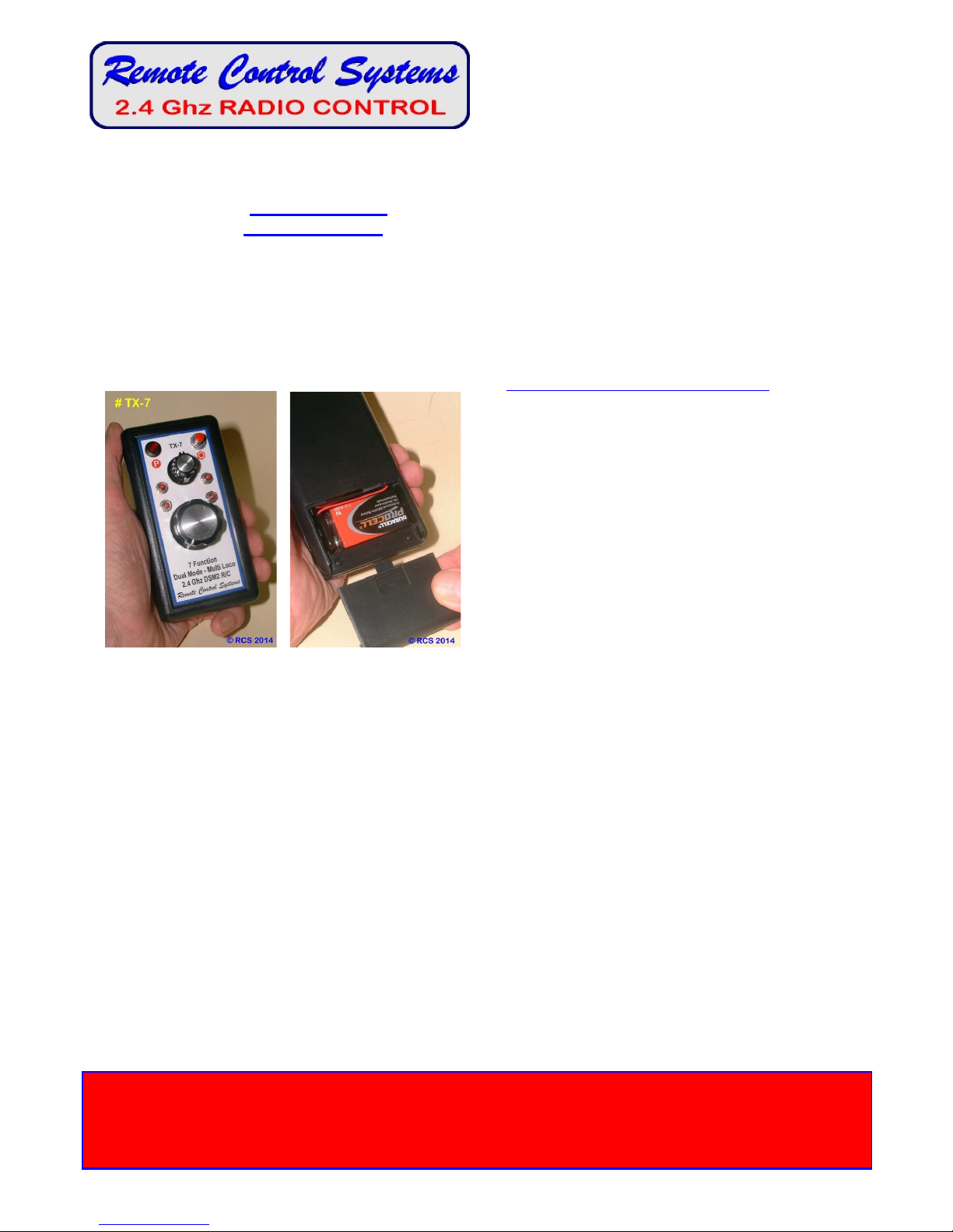
THE RCS TX-3, TX-5 and TX-7 HANDPIECES.
THERE ARE SEPARATE INSTRUCTIONS FOR USE WITH ANY 2.4
GHz R/C WITH 4 OR MORE CHANNELS.
THOSE OTHER INSTRUCTIONS REFER SPECIFICALLY TO THE
SPEKTRUM DX5e 2.4 GHz R/C.
THEY ALSO APPLY TO THE DX4e, DX6i & PLANET T5. N.B.
YOU CANNOT MIX BRANDS OF R/C.
THE RCS #OMEGA-3v5 SYSTEM IS IN ONE PART WITH
SERVO LEADS WHICH PLUG INTO ANY DSM2 COMPATIBLE
RX.
OR; USE ANY BRAND OF R/C WITH THE ADDITION OF FOUR
SERVO LEADS CONNECTED TO THE 6 WAY SCREW
TERMINAL ON THE ESC AND PLUGGED INTO THE
APPROPRIATE CONNECTIONS ON THE RX.
INSTRUCTIONS.
THESE INSTRUCTIONS REFER TO OPERATING PROGRAMS Av1 & Bv1.
AN ESC WITH OPERATING PROGRAM AV1 CAN BE USED WITH ANY TYPE OF DSM2 TRANSMITTER.
#OMEGA-3v5s HAS BEEN CALIBRATED AT THE FACTORY. ONCE RX IS “BOUND” TO TX THE SYSTEM IS READY TO USE AS IS.
THERE ARE MANY FEATURES WITHIN THE SYSTEM WHICH CAN BE PROGRAMMED. YOU WILL NEED TO DOWNLOAD THE FULL
INSTRUCTION MANUAL FROM THE RCS WEBSITE. THE PUSHBUTTON ON THE ESC PCB IS ONLY USED FOR PROGRAMMING.
DO NOT PRESS THE ESC BUTTON DURING OPERATION.
DO NOT CONNECT TO MAINS POWER (110 – 240V AC).
THE #OMEGA-3v5s CAN BE USED WITH ANY FILTERED DC SUPPLY SUCH AS BATTERY POWER.
THEY HAVE CONSTANT BRIGHTNESS DIRECTIONAL LIGHTS & 2 SOUND TRIGGERS.
THE FOLLOWING MAXIMUM VOLTAGES MENTIONED ARE THE NOMINAL VOLTAGE & TAKE INTO ACCOUNT THAT FULLY
CHARGED BATTERIES CAN & DO EXCEED THE NOMINAL VOLTAGE.
USE 14v – 20v FOR THE #OMEGA-3v5s. A high voltage version is available.
We tested this system three times during manufacture. It was working normally when it left our factory.
If damage in transit has occurred, please return to place of purchase for attention.
THE ESC IS GUARANTEED FOR ONE YEAR.
The solid state motor driver output IC is guaranteed for life.
You will supply a locomotive or trail car, the 14 – 20 volt traction batteries (depending on ESC), a fuse,
ON-OFF switch and wires where necessary, to connect the ESC to the battery and motor(s).
Where soldering is necessary, we recommend a low wattage soldering iron and resin core solder.
TO AVOID CONFUSION WITH OTHER OPERATORS, WE SUGGEST YOU MARK THE TX TO
SHOW WHICH LOCO IT OPERATES.
CAUTION
DO NOT ATTEMPT TO ALTER THE TUNING OF THE RADIO EQUIPMENT.
DO NOT USE RADIO CONTROL EQUIPMENT IN THUNDERSTORMS.
CHILDREN UNDER 12: ADULT SUPERVISION RECOMMENDED DURING USE.
Page 2
- 2 -
INSTALLING THE #OMEGA-3v5s ESC.
The #OMEGA-3v5s ESC uses any DSM2/DSMX 6 x Channel RX’s including our own “Auto Binding” DSM2-EM(AB)
Rx & SPEKTRUM or the ORANGE brand from Hobby King. Servo leads are supplied for connecting the ESC to the RX.
Always make sure the servo leads are connected to the correct sockets on the RX.
THESE INSTRUCTIONS REFER TO OUR OWN DSM2 TX HANDPIECES.
CONTROL KNOBS.
The TX-3, TX-5 & TX-7 handpieces all use a small knob for selecting direction change & a large knob for speed control.
USING EXTRA SERVOS.
The #OMEGA-3V5s ESC permits the operation of a regular servo using Ch # 5. Simply plug the servo leads the right
way around into the Ch # 5 servo header so marked in the RX. See the ESC diagram.
SOUND TRIGGER CONTROLS.
The TX-3 has one Ch # 5 pushbutton for triggering a sound system. Plug the Ch # 2 servo lead into the Ch 5 position on
the RX. Activates F2 on the trigger outputs. Or use as a mechanical servo action.
The TX-5 has two knobs for sound triggers although they can be awkward to use. Outputs are F1, F2, F3 & F4. The Ch
5 pushbutton is also available. See TX-3 above.
The TX-7 has four pushbuttons on the handpiece that are intended to trigger 4 x sound effects or control accessories.
They operate F1, F2, F3 & F4 on this ESC. The Ch 5 pushbutton is also available. See TX-3 above.
A pushbutton on the ESC pcb is used for initial speed calibration and making system program changes such as Start/Max
voltage, default direction start, system reset & sound trigger outputs from momentary to latch ON – OFF. If you need to
calibrate the system you must download the full instruction manual from the RCS website. See URL on page # 1.
LOCOMOTIVE SEPARATION.
2.4 GHz R/C systems are not separated with crystals. Every TX has a unique identifier code. They are all legal for air &
ground use. Most SPEKTRUM RX’s (and DSM2 clones) can be “BOUND” to the TX 20 handpieces.
“BINDING” must be done before the system can be used. See page # 4.
You can mount the #OMEGA-3v5s PCB with double stick tape or non conductive silicone. Do not allow metal objects
to touch the rear of the PCB. Damage to the PCB may result.
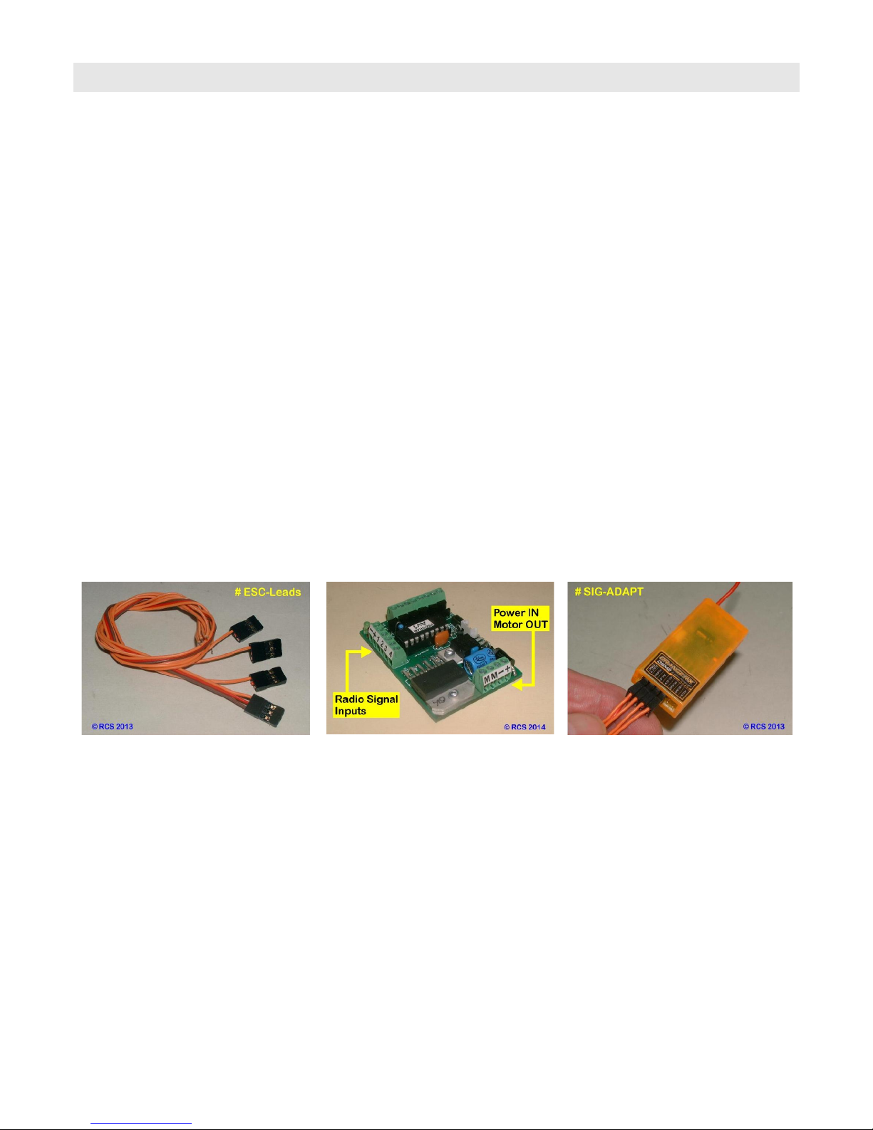
The
# ESC-LEADS
kit.
These connect any 2.4 GHz RX to the
# OMEGA-3v5 ESC.
Insert the
# ESC-LEADS
as follows.
1 = Throttle. 2 = Aileron.
3 = Elevator. 4 = Rudder.
Insert the 1 x 3 way servo cable into the
DSM2 RX #1 Throttle servo output.
Single leads go into A (2), E (3) & R (4).
PLACING RX ANTENNA.
It does not matter where you place the RX and antenna(s). We have at least 150’ + range with the system in plastic
locos. There is NO “glitching” or “Rusty Bolt Effect”. 2.4 GHz RX’s have been successfully used for some years with the
RX & antenna inside a dummy water tank of a live steam loco and inside expensive brass electric locos.
Turn the 2.4 GHz TX OFF to save the batteries & the loco will “Cruise” along until the TX is turned ON again & manual
control resumed.
Page 3
- 3 -
INSTALLATION OPTIONS.
There are a number of different ways to wire up a loco. See wiring diagram pages. The two most popular are:
1. The simplest method is to connect the motor outputs (M & M) to what were the now isolated track pick ups. The loco
will behave exactly as it would if it were running on track power. That is, the lights for example will rise and fall with motor
voltage or come on before the loco starts moving. No other changes are necessary. This is ideal for trail car set ups.
2. Rewire the lights so that the loco will have constant brightness auto reversing head and tail lights. This can get
complicated and is not advised unless the installer has some experience. See below.
POWER SOURCES.
The #OMEGA-3v5s ESC can only be used with battery power as it comes. Ensure the battery pack is fully charged
before use. Contact RCS for information on how to use the ESC with a constant track voltage.
N.B. The absolute minimum voltage is 12 volts. If you use any less voltage the system will still respond, as in
the LED’s will light and respond to direction change, but the motor drive output will not work.
Connect the traction battery, which MUST BE FUSED, as per the wiring diagram.
RCS R/C offers a variety of installation kits for on board use such as the # BIK-U3/6 which has screw terminals to simplify
installations. For trail car installations we also have the # BIK-TC2/3 and # BIK-TC5.
MOTOR CONNECTION.
With #OMEGA-3v5s connect the motor(s) as per the wiring diagrams to M & M. The M + motor output is positive (+) in
a forward direction. Our extensive testing has shown the system doesn’t need any motor “Noise” suppression.
SHORT CIRCUIT & OVERLOAD PROTECTION.
RCS ESC’s are self protecting. Although there is output overload and short circuit protection built into them, it is
essential the battery supply be fused for overall system protection. See the wiring diagram pages.
LOCOMOTIVE LIGHTING.
RCS ESC’s have transistor controlled directional lighting. Please note: Maximum current is 100 ma per terminal.
N.B. Any greater load than 200 ma will kill the switching transistors which are not covered by warranty.
2 – 3 LED’s per output will be just fine but, please do not try and run multiple incandescent bulbs with the outputs. .
The #OMEGA-3v5s requires connecting the lights to the 4 x screw terminals as per the ESC diagram.
+ = Common + voltage (input less .7 volt). - = Common – (ground), F = Front Light, R = Rear Light.
IT IS MOST IMPORTANT THAT THE LIGHT BULBS BE COMPLETELY ISOLATED FROM ANY OTHER WIRING.
Instead of rewiring some locos, sometimes it is much simpler to control the regular loco wiring by simply reversing the
traction battery voltage. You can use the # RELAY-1v2 to do this as it can save a lot of wiring in many locos. It is
especially useful in USA Trains® locos to control incandescent bulbs or LED’s up to 1 amp & smoke features.
Please note: If the # RELAY-1v2 is used, the lights will flash alternately, not together as with transistor outputs.
When the system is in neutral only one set of lights will be lit.
The instructions assume the operator has used the available front & rear transistor lighting outputs or # RELAY-1v2.
If you do not have any lighting outputs connected you MUST be able to observe the LED’s on the ESC.
DEFAULT START UP DIRECTION.
In case the system is wired back to front the default direction will also need to be reset. See page # 6 section
3.4. You may also need to reverse the F & R lighting wires.
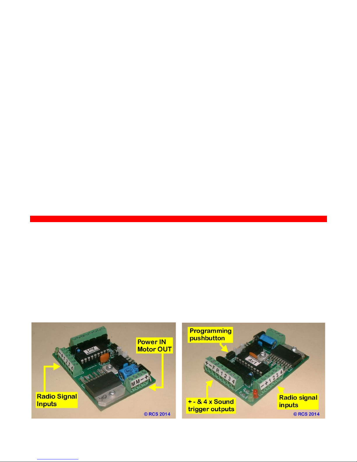
THE PICS BELOW SHOW:
1. Where the pushbutton is located on t
he #OMEGA-3v5s
PCB for speed calibration and programming.
2. Where the controlled lighting outputs (+ - F & R) and function triggers (1, 2, 3 & 4) are connected.
Page 4

- 4 -
SETTING UP THE #OMEGA-3v5s ESC.
THESE INSTRUCTIONS REFER TO THE
RCS TX-3, TX-5 & TX-7
2.4 GHz 5 CHANNEL R/C.
ALL THE ABOVE TX’s USE THE SAME BINDING PROCEDURE.
FOR BINDING, CALIBRATING & USING WITH A PLANET OR SPEKTRUM STICK RADIO REFER TO:
http://www.rcs-rc.com/app/webroot/PDF/OMEGA-3/ESC-TEXT/OMEGA-3v3.pdf
Unless the TX and RX have already been bound and the system calibrated prior to using this system,
there are two procedures that must be carried out by the operator,
1. “BINDING”.
The 1st procedure is to “BIND” the receiver (RX) to the Transmitter (TX).
“AUTOMATIC BINDING”.
Our # DSM2-EM(AB) has this feature.
1.1 Switch on Rx. LED will flash once every 2 seconds. Wait 20
seconds until Rx LED flashes rapidly.
1.2 Then press & hold TX bind button & switch TX on. TX LED will
flash more slowly for several seconds. When Rx LED starts flashing let
go of both TX buttons.
1.3 Bind is complete when Rx LED stays On.
1.4 If the system has been calibrated the ESC LED & both loco lights
will immediately blink three times
If LED does not come on within 10 seconds or continues flashing every
2 seconds (= scanning), the bind has failed. Switch TX and RX off,
move them closer together or further apart and retry.
Binding is most reliable when no other 2.4 GHz R/C systems are on.
& then go to solid ON.
“MANUAL BINDING”. Simply insert the binding plug into the bind
socket on the regular DSM2 RX. When the RX flashes rapidly follow
the RX binding procedure above. Remove the binding plug before
commencing operation.
When “BINDING” is complete the RX LED will change to solid ON. If
the system has been calibrated the ESC LED & both loco lights will
immediately blink three times & then go to solid ON.
N.B. If manually binding, the “BINDING” plug MUST be removed
BEFORE the SYSTEM is turned OFF.
Once the “BINDING” plug is removed & stored safely. The R/C system
is now ready for speed calibration. Not necessary if already done.
Please note the LED’s on the ESC pcb & the front and rear lights (if fitted) will stay OFF until “BINDING” is completed.
The loco will always give a very slight jerk at switch ON. This is normal. See Page # 9.
Page 5

- 5 –
2. CALIBRATION.
All RCS # OMEGA-3v5s systems are pre-calibrated when sent out, using one of our own TX handpieces.
Please test the system before re-calibrating it.
If you are going to use a stick type TX, the end points may be different so re-calibration may be necessary.
Assuming the RX has been correctly plugged into the ESC the system will perform as described later.
The 2nd step in system preparation is to calibrate the direction & throttle knobs. Even though this step is only needed
once when first setting up an uncalibrated ESC, from time to time it is advisable to run through the procedure to ensure
the best possible system performance is achieved.
A pushbutton is mounted on the pcb for both Calibration & system Programming. See 2.2 below right.
You can calibrate & program the system external to the loco by adding the separately available plug in # P-BUTTON.
2.1
Turn the TX-7 ON.
Make sure Throttle knob is set
to Min. (i.e. fully CCW).
2.2
Press and HOLD ESC push-button down & turn the ESC/Rx ON. Release
the pushbutton when LED’s light.
Reaction; Both ESC LED’s & both front & rear lights will turn solid ON & stay ON for 6 seconds waiting for the TX and
RX to link up. Once linked both ESC LED’s & both front & rear lights will flash rapidly.
2.3
Twist the small direction knob right & left full travel a
couple of times. Pause briefly each way then return
knob to the middle position.
2.4
Rotate throttle knob from Min to Max & back a
couple of times. Pause briefly at each extreme then
return knob to Min (CCW) setting.
2.5 Press & release the ESC pushbutton to exit Calibration mode.
Reaction; Both ESC LED’s & both loco lights will blink three times at a slower rate & both lights will go to solid ON.
The system is in neutral and ready to operate. Either turn the loco and TX OFF for later use, or proceed to page # 6.
Page 6

- 6 -
3. PROGRAMMING.
Operating features of t
he #OMEGA-3v5s
system can be programmed from the TX using the ESC pushbutton.
Programming can only take place when the system is in neutral.
3.1 START VOLTAGE. This feature is designed to equalise the starting voltage of dissimilar locos.
3.2 TOP SPEED VOLTAGE. This can limit the top speed available. Either for speed matching locos or, for limiting the
top speed of one loco, say, when the system is being operated by children.
3.3 MOMENTUM. Toggle momentum control ON or OFF.
3.4 DEFAULT DIRECTION. Re-set the direction of a loco when it is to run back to back with another loco.
3.5 SYSTEM RESET. This takes # 1 & # 2 back to the factory default if incorrectly set.
3.6/7/8/9 SET SOUND TRIGGERS 1, 2, 3 & 4 from MOM (Default) to Latch ON - OFF.
HOW TO USE THE PROGRAMMING FEATURE.
Turn the TX & Loco ON. The RX & loco lights will stay OFF until the TX & RX are linked. Then blink 3 x times & go solid
ON. The system will then be, & must stay, in neutral. Or, if you have been running, return to neutral before programming.
Then press the pcb pushbutton once & the lights will go out. The system is now in Programming Mode.
SPEED MATCHING.
If you have two or more locos that have dissimilar starting and top speeds, you can adjust those voltages so the locos will
be fairly accurately speed matched across the speed range. It has been our experience that absolutely accurate
matching is not really needed for smooth performance. The trade off is, the top speed of a consist of locos controlled by
one TX will be limited to the top speed of the slowest loco.
3.1 START VOLTAGE. We suggest you test the locos you wish to match one at a time to find out and note the knob
setting at which the slowest starting locos begin to move.
Then, with the slowest loco stopped and the direction set to neutral:
Move the throttle knob to the loco start speed desired. i.e. to the knob position where the loco started moving.
Then twist the direction knob to the right and back again ONCE only. The lights will blink ONCE with the twist.
Wait a couple of seconds for the lights to blink ONCE again indicating the new start voltage setting has been stored in the
system memory. Then move the large throttle knob back to zero (OFF) position. i.e. knob is fully CCW.
Then press and release the pushbutton on ESC. The lights will blink three times and then go to all solid ON. i.e. Neutral.
Repeat the procedure if the setting is incorrect.
3.2 TOP SPEED VOLTAGE. If speed matching, we suggest you test the locos you wish to match one at a time to find
out the knob setting at which the fastest loco matches the top speed of the slowest loco.
Then, with the fastest loco stopped and the direction set to neutral:
Move the throttle knob to the lower top speed desired for the loco. i.e. to the knob position where the fastest loco
matched the top speed of the slowest loco.
Then twist the direction knob to the right and back again TWICE only. The lights will blink ONCE with each twist.
Wait a couple of seconds for the lights to blink TWICE again indicating the new top speed voltage setting has been stored
in the system memory. Then move the throttle knob back to zero (OFF) position. i.e. knob is fully CCW.
Then press and release the pushbutton on ESC. The lights will blink three times and then go to all solid ON. i.e. Neutral.
Repeat the procedure if the setting is incorrect.
OR: When children are using the loco, you can follow the same steps to limit the top speed of any loco.
3.3 MOMENTUM. Toggle momentum control ON or OFF.
Twist the direction knob to the right and back again THREE times only. The lights will blink ONCE with each twist.
Wait a couple of seconds for the lights to blink THREE times again indicating the default momentum ON – OFF setting
has been stored in the system memory.
Then press and release the pushbutton on ESC. The lights will blink three times and then go to all solid ON. i.e. Neutral.
3.4 DEFAULT DIRECTION. To re-set the default direction of a loco to run back to back with another loco:
Twist the direction knob to the right and back again FOUR times only. The lights will blink ONCE with each twist.
Wait a couple of seconds for the lights to blink FOUR times again indicating the default direction setting has been stored
in the system memory.
Then press and release the pushbutton on ESC. The lights will blink three times and then go to all solid ON. i.e. Neutral.
3.5 SYSTEM RESET. To take # 3.1 & # 3.2 back to the factory default if incorrectly set:
Twist the direction knob to the right and back again FIVE times only. The lights will blink ONCE with each twist.
Wait a couple of seconds for the lights to blink FIVE times again indicating the start & top speed voltage settings have
been returned to default in the system memory.
Then press and release the pushbutton on ESC. The lights will blink three times and then go to all solid ON. i.e. Neutral.
3. 6/7/8/9 SET SOUND TRIGGERS F2, F3 & F4 from MOM (Default) to Latch ON - OFF.
# F2, twist the direction knob to the right and back again SEVEN times only. The lights will blink ONCE with each twist.
Wait a couple of seconds for the lights to blink SEVEN times again, indicating the trigger has toggled to latch ON-OFF.
Then press and release the pushbutton on ESC. The lights will blink three times and then go to all solid ON. i.e. Neutral.
Repeat procedure for trigger # F3 (EIGHT pushes). # F4 (NINE pushes).
Repeat procedure to change either of these 3 x triggers back to MOMENTARY from Latch ON – OFF.
Page 7

- 7 -
OPERATING THE OMEGA-3v5s ESC.
THE THROTTLE KNOB MUST BE AT MIN i.e. ALL THE WAY CCW, BEFORE TURNING THE SYSTEM ON.
Always turn the TX on first. Then turn the loco ON. The loco will give a slight jerk (See page # 8) & the ESC & loco lights
will stay OFF. After between 2 - 8 seconds the TX & RX will recognise each other. The RX LED and both ESC LED’s will
come ON & not blink. After another 6 seconds both ESC LED’s & both front & rear loco lights (if fitted) will blink three
times & then all lights will go to solid ON.
N.B. In order to select a direction the throttle knob must be at MIN and the system must be in neutral.
4.1 FORWARDS.
To select forwards direction twist the Direction knob fully to the right (CW) & return to neutral.
The Red LED on ESC & rear loco light will go out. The green LED on the ESC pcb & the front loco light will stay ON.
If the OMEGA-3V5s ESC default motor & lights direction is incorrect please see Page # 6 PROGRAMMING of the full
instructions. Use the 3.4 DEFAULT DIRECTION feature to make changes.
4.2 SPEEDING UP. Gently twist the knob clockwise (CW). The loco will accelerate away after slightly turning the knob.
The speed is proportional to the knob position with a small amount of momentum built in to prevent sudden jerky
movements. Let the knob go once the desired speed has been reached. The speed will stay the same until the knob is
rotated CW or CCW. Min - Max speed takes 2 x seconds.
4.3 SLOWING DOWN. Turn the knob CCW back to the desired speed. Max - Min speed takes 2 x seconds.
4.4 STOPPING. Turn the knob completely CCW back all the way to stop. The ESC LED & front light will be ON.
4.5 REVERSE. You must completely stop the loco first. The Throttle knob must be at Min. (i.e. fully CCW). Then:
Twist the direction knob fully to the left (CCW) & back to the neutral position to reach neutral.
Both ESC LED’s & both front & rear loco lights (if fitted) will go to solid ON.
Twist the direction knob to the left (CCW) again & back to the neutral position to set reverse.
The Green LED on ESC & front light will go out. The Red LED on the ESC pcb & the rear light will stay ON.
To speed up, slow down & stop in reverse see 4.2 SPEEDING UP, 4.3 SLOWING DOWN & 4.4 STOPPING above.
CONTROLLING SOUND TRIGGERS.
SOUND SYSTEM TRIGGERS.
For the sound triggers to work there MUST be a common ground (-) connection between the ESC and sound system.
1. Sound powered by a separate battery. Connect the grounds on both the ESC and sound system.
2. Sound powered by ESC. Already has a common ground.
The #OMEGA-3v5s ESC has 4 x sound triggers controlled by the four small push buttons on the TX-7 handpiece.
The Ch # 2 servo lead must go to Ch # 2 on the RX.
The Ch # 4 servo lead must go to Ch # 4 on the RX.
The two LH pushbuttons F1 (top) and F2 (bottom) control terminals # 1 (Green) & terminal # 2 (Purple)
The two RH pushbuttons F3 (top) and F4 (bottom) control terminals # 3 (Brown) & terminal # 4 (Grey)
You can activate any sound with any trigger depending on which pushbutton you want to operate the sound with.
The default for each is Momentary. F2, F3 & F4 are programmable for latch ON – OFF instead. See page # 6. 3.6/7/8/9.
N.B. With the TX-2s only, the F1 button will control output # 2 and the F2 button will control output # 4.
You can also use the two accessory knobs on the TX-5 by twisting to the right or left to activate the sound .
Just remember to return the knobs to the middle neutral position.
When using with Momentary function, press the button until the sound is activated. Release button to turn sound OFF.
When using with a Latch ON – OFF function, press and hold the button for one second until the sound is activated. Then
release the button and the sound will stay ON. Press the same button for one second & release to turn the sound OFF.
They can be used as is with most sound systems such as Sierra®, Phoenix®, Dallee® & MyLocosound®.
Sierra will require the additional purchase of one # SSI-12v5 so that Sierra can function correctly.
USING PUSHBUTTONS FOR SERVO FUNCTIONS.
With #OMEGA-3v5s ESC the TX-7 pushbuttons can be used to control servos instead of sound triggers.
F1 & F2 give half servo movements from neutral on Ch # 2. Plug servo into appropriate channel on the RX.
F3 & F4 give half servo movements from neutral on Ch # 4. Plug servo into appropriate channel on the RX.
Ch # 5 SERVO FUNCTION.
The #OMEGA-3v5s ESC has 1 x output available for a mechanical servo function such as Kadee servo uncoupler.
Simply plug the Kadee into the Ch # 5 terminal on the RX. Activate with the large red pushbutton top right on TX. Servo
goes from one extreme of travel to the other. Servo goes back to start position when button is released.
Page 8

- 8 -
THE #OMEGA-3v5s ESC MU’ing LOCO CONSISTS.
MULTIPLE LOCOS IN A CONSIST.
The #OMEGA-3v5s ESC is capable of MU’ing multiple locos into one consist of locos.
If you intend to do this often we strongly recommend you use the # DSM2-EM(AB) in all locos. These bind automatically
which is much easier to use than a binding plug. It is also a good idea to purchase the optional extra # LED 3mm-G so
you can observe externally what the RX is doing during binding.
Add as many speed matched locos to the loco consist, as you like. Each loco must be bound to the controlling TX.
Follow the “BINDING” procedure described above on page # 4. Remember the loco lights will be off during binding.
The lights come on once binding has been completed. This is intended as a confirming reference action.
If the loco to be added has already been speed calibrated, there is no need to repeat the calibration step.
The operating program permits reversing default direction & speed matching of locos. Settings for these features are
stored in the ESC so that any loco can be acquired by any TX. See page # 6. 3.1/2/4.
HOW TO ADD LOCOS TO A CONSIST.
Turn the first loco OFF. Turn the second loco ON and drive it into position. Turn the first loco back ON.
The lock in feature of the system ensures the direction is set positively. Just make sure both locos are at zero output
before changing direction. To make sure the direction is set correctly for all locos in the consist, twist the direction knob
twice from neutral. Once the direction is set it cannot accidentally change back to neutral when loco is running.
DELETING LOCOS FROM A CONSIST.
Turn OFF the “to be retained” loco. Leave the “to be deleted” loco ON & drive it away, or, rebind it to a
different TX
for use by another operator. See page # 4.
THE #OMEGA-3v5s ESC TROUBLESHOOTING.
IF NOTHING WORKS AT ALL:
WHAT TO EXPECT WHEN FIRST TURNING THE SYSTEM ON.
WHEN THE LOCO IS SWITCHED ON, THE PCB LED’s DO NOT LIGHT OR BLINK.
This is most likely caused by the throttle knob not being at MIN. Turn the knob fully CCW to MIN.
WHEN THE LOCO IS SWITCHED ON THE LOCO MAY JERK SLIGHTLY.
This is normal. The slight jerk indicates power is connected to the system, the IC has powered up and output
power is connected to the motor..
NEVER PRESS THE ESC PUSHBUTTON WITH THE LOCO TURNED ON
UNLESS YOU INTEND TO CALIBRATE OR PROGRAM THE SYSTEM
PROBLEM. You pressed the pushbutton to exit Calibration mode but the lights keep on flashing.
You may have mis-plugged the RX servo leads into the channel sockets.
SOLUTION. Turn system OFF. Remove & replace the RX servo leads into the correct channel # sockets.
As odd things can happen if this occurs, we strongly suggest you reset the system. See page # 6. 3.5.
Then re-calibrate the speed and direction settings. See page # 5.
WHEN THE SYSTEM IS FIRST TURNED ON, THE LIGHTS UNEXPECTEDLY BLINK RAPIDLY.
This is because you actually pressed the ESC pushbutton & the system has entered calibration mode.
CAUTION: DO NOT PRESS THE ESC PUSHBUTTON . You will lose any previous calibration settings.
You can proceed with system Calibration. (See page # 5 of the instructions). OR:
SOLUTION Turn RX OFF & ON again. Normal system control will be restored.
WHEN THE LOCO IS SWITCHED ON, ALL LIGHTS COME ON WITHOUT BLINKING & NOTHING WORKS.
This can occur when the TX is switched ON after the loco, with the throttle knob not fully OFF (down).
SOLUTION. Ensure the throttle knob is completely OFF. The lights will then blink to indicate linking.
THE LOCO DIRECTION SET KNOB IS BACKWARDS.
When the direction is set to forwards the front light must come ON. If the lighting is correct and the speed is
backwards, you must reverse the wiring to the motor(s).
WEIRD ESC BEHAVIOUR FOR NO APPARENT REASON, DURING OPERATION.
If the lights start flashing during operation, stop the loco. Turn it OFF and then ON again to resume
normal operation.
PLEASE ADVISE US OF ANY OTHER PROBLEMS ENCOUNTERED & WE WILL INCLUDE THEM HERE.
Page 9

Page 10

 Loading...