

Page 1
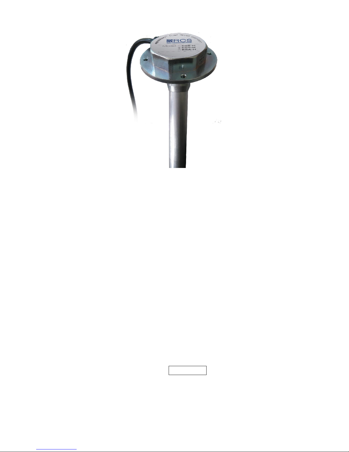
"EPSILON"
®
FUEL LEVEL SENSOR
"ESx - H" model
User Manual
EH.000 UM
_v. 171228_
Page 2

2
CONTENTS pages
INTRODUCTION………………………………………………………………3
1 SPECIFICATION AND PRINCIPLE OF OPERATION ...................... 3
1.1 Specification and operation of device ................................................................ 3
1.2 Specification and operation of device components .......................................... 10
2 INTENDED USAGE ............................................................................. 11
2.1 Operating restrictions ....................................................................................... 11
2.3 Device preparation for use ............................................................................... 11
2.4 Use of device .................................................................................................... 11
3 TECHNICAL SUPPORT ...................................................................... 12
3.1 Technical support of device ................................................................................... 12
4 TECHNICAL MAINTENANCE .......................................................... 13
4.1 Malfunctions diagnosis of device and troubleshooting actions ....................... 13
5 TRANSPORTATION AND STORAGE .............................................. 17
The present installation manual is intended to provide information necessary for
users during operation and maintenance of “Epsilon” fuel level sensor “ESx-H model”
(hereinafter – sensor, FLS or product).
Personnel familiar with the present manual is allowed to install the sensor.
Page 3

3
1 SPECIFICATION AND PRINCIPLE OF OPERATION
1.1 Specification and operation of device
1.1.1 Intended use
Sensor is purposed for fuel level measurement in fuel tanks of vehicles and
stationary fuel tanks. Sensor can be used to measure level of other nonconductive
liquids.
ES2-H, ES4-H sensor can be used with equipment that supports unified
communication protocol Epsilon Data Exchange. (hereinafter - EDE).
ESA-H model sensors can be used with analogue interface devices.
Sensor has electronic galvanic isolation through interface and power circuits.
Sensor is compatible with different GPS tracking devices, such as:
- "Автограф";
- "Скаут";
- "Locarus";
- "Intellitrac";
- "Patriot";
- "Teletrack";
- "Teltonika";
- "M2M – Cyber GLX";
- "Ruptela FM";
- "BCE FM blue» and others.
Additional features
Model ES2-H sensors provide frequency interface (signal outputting from 500
to 1500 Hz frequency with linear frequency dependence vary with measured level of
fuel). Also, model ES2-H sensors can provide analogue interface (signal outputting
from 0 to 10 V voltage with linear voltage dependence vary with measured level of
fuel), when using FV-10 frequency-to-voltage converter.
Page 4

4
1.1.2 Technical specification
Table 1.1
Parameter or characteristic name
Unit
Value
Note
(Note
number)
1
2 3 4
Operational temperature range
°
С
– 40 … + 75
Ingress protection rating
IP67
Mode of operation
Continuous
Upper variation range of level measurement
mm
from 150 to 2000
(1)
Ranges of permissible reduced error of level
measurement
%
±1,0
(2)
Variation range of relative dielectric
permittivity in controlled fuel (ε)
-
1,5…5,0
The period of measurement results averaging
Sec.
0…128
Code length of presentation of measurement
results
bit
10;12;14;16
(3)
Temperature measurement range of
measuring head
°
С
- 40…+ 85
Code length presentation of measuring head
temperature
bit
8
Power supply voltage, operational range
V
+9.5…+36
Nominal
value
Current consumption, max
mA
25
Acceptable exposure of impulse voltage
through power circuits
V
+120, long-term
+ 180 V, 1 sec.
-1000 V, long-term
(4)
Acceptable short-term exposure of potentials
difference between signal ground and body of
measuring head
V
±1500 V, 1 sec.
Digital interface
RS-485
ES4-H
RS-232
ES2-H
Exchange rate through the serial port
bps
2400, 4800, 9600,
19200, 38400,
57600, 115200
programm
ed
Page 5
5
Table end 1.1
1
2 3 4
Frequency interface (when using ES.700
compatible device)
Hz
500…1500
ES2-H
Analogue interface
V
0…10
ESA-H
model
Analogue interface (when using frequency to
voltage converter FV-10)
V
0…10
ES2-H
Flange version
4 holes, 4,2 mm
Height of a measuring head over a tank top,
including flange and gasket, max
mm
26
Notes for table 1:
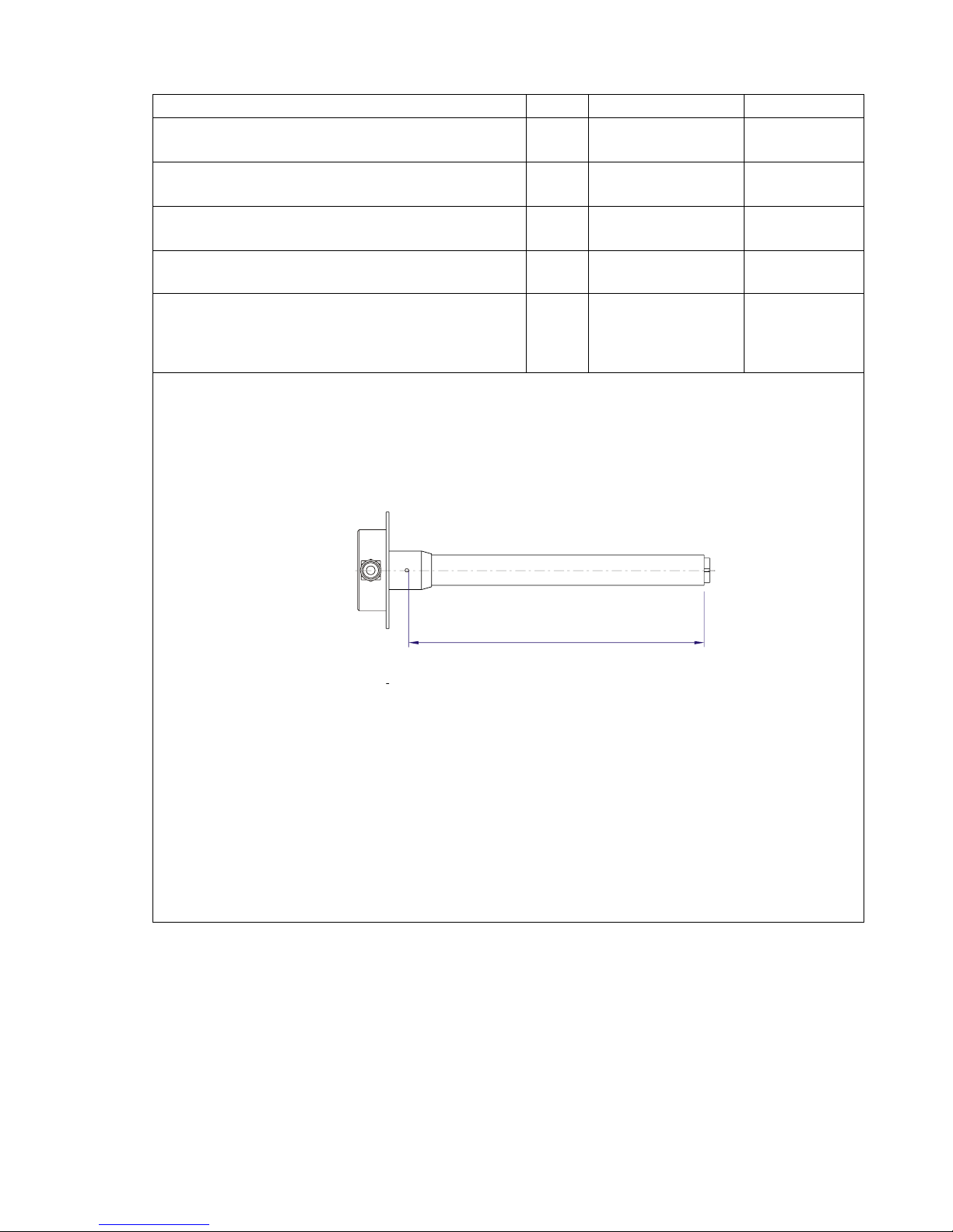
1 Level measurement range – Ly distance from the lower cut of metal tube (lower threshold
of measurement) to the lower edge of drain orifice (highest threshold of measurement),
according to Figure 1.1:
Figure 1.1 - Level measurement range
2 When testing fuel with the same dielectric permittivity as the fuel which was used during
calibration process. To ensure precise monitoring with other fuel grades (according to
dielectric permittivity of fuel grade) adjustment of calibration table must be used.
3 Data output has two layouts: 16 bit and 10/12/14/16 bit. Capacity 10/12/14/16 bit is
switched according to the program. 10 bit value is set by default.
4 Pulse parameters according to GOST (ГОСТ) 28751 (severity degree 3 for 24V on-board
power use).
Ly
Page 6
6
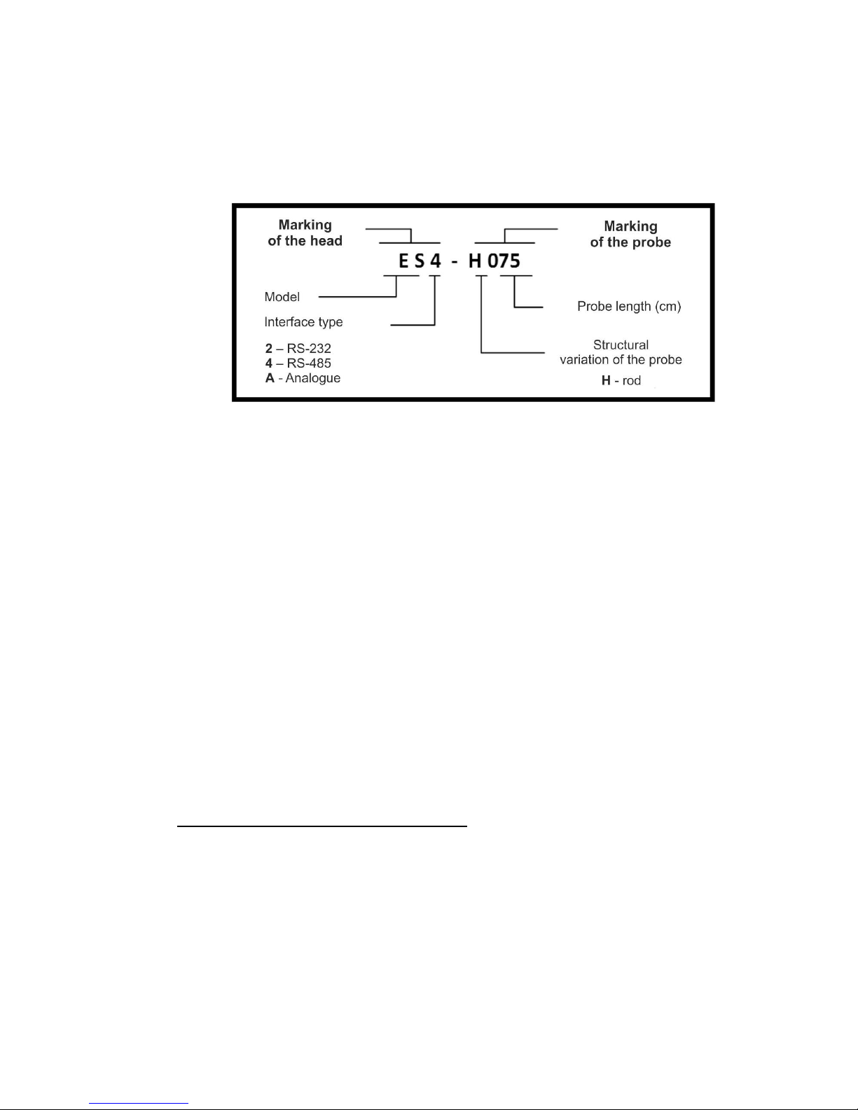
1.1.3 Marking of device
Sensor has different marking, depending on the interface type and fuel probe
length (figure 1.2):
Figure 1.2 – Sensor legend
"Epsilon ES2-H" – exchanges data through RS-232 interface.
"Epsilon ES4-H" – exchanges data through RS-485 interface.
"Epsilon ESA-H" – exchanges data through analogue interface.
1.1.4 Device ordering
1.1.4.1 When ordering sensors marking includes:
- title name;
- sensor name - "Epsilon “
- model marking;
- interface type;
- fuel probe length in centimeters;
1.1.4.2 Example of “Epsilon” sensor marking for registration when ordering as
well as in specification of other products it can be used with:
Fuel level sensor "Epsilon" ES4-H-075
where "Fuel level sensor" is a title name;
"Epsilon" – sensor name;
"ES-H" – model;
"4" – interface RS-485;
"-" – spacer;
"075" – fuel probe length 75 cm;
Page 7

7
1.1.4.3 Evaluation of fuel probe length when ordering (See figure 1.4)
Figure 1.4 - Evaluation of fuel probe length when ordering
To evaluate the proper fuel probe length it is necessary to measure fuel tank
depth in place of intended sensor installation and to calculate length of fuel probe
according to the formula:
Lm = L- ∆,
where Lm – approximate length of fuel probe as per order;
L– tank depth in place of intended sensor installation;
∆ - distance between measuring part and tank bottom.
Recommended values for distance ∆:
- ∆ = 15…20 mm – for rigid metal tanks (the deeper the tank the bigger
the distance);
- ∆ = 30 mm – for tanks without enough rigidity (such as plastic tanks of
considerable height).
During installation process, the necessity of reducing fuel probe length may arise
(on-site).
You can find the procedure of reducing fuel probe length in “EH.000-EN IM_
Installation Manual”.
L
D
Page 8

8
1.1.5 Delivery set
1.1.5.1 Basic delivery set
Table 1.2
Name
q.
Note
Assembled sensor
1
Assembled with ~ 40 cm cable
Interface cable
1
~ 7 m long
Self-drilling screw
1
With hole for safety seal
Self-drilling screw
3
∅4,2 х 19 mm
Gasket
1
Tamper-evident seal
1
With wire for safety seal
Fuse SI 0,1 A
1
Zip tie
15
200 х 3.6 mm
Passport
1
1.1.5.2 Additional accessories and documentation
(delivered by additional order)
Table 1.3
Name
Ref.
Note
EA2 sensor connection cable to PC
IEC EA С.100
For EA2-H models
EA4 sensor connection cable to PC
IEC EA С.100-01
For EA4-H, ESA-H
models
Interface adapter
USC234-A
For ESA-H models
Matching device
ES.700
For EA2-H models
Frequency-to-voltage
converter
FV-10
For EA2-H models
CD with software
EA.000 CD3
For ES2-H, ES4-H
models
CD with software
EH.000 CD3
For ESA-H models
Installation manual
EH.000-EN IM
User manual
EH.000-EN SM
Page 9

9
1.1.6 Design and operating principle
A measuring head together with a sensor probe submerged in fuel provides fuel
level measurement.
Sensor probe acts as a condenser, which capacity linearly depends on a fuel level
in a tank.
Measuring head of the sensor performs linear conversion of sensor probe volume
into fuel level digital code, processes acquired digital information with averaged
results, measures sensor head temperature and outputs data in unified EDE protocol
through RS-232 or RS-485 interfaces (for ES2-H and ES4-H models) or through
analogue output (for ESA-H model). Fuel level data outputs in 16-bits (additionally,
data output can be selected in 10-, 12-, 14- or 16-bits), temperature data outputs in 8bits.
To measure the volume of monitored fuel calibration of fuel tank must be
performed. This procedure determines volume-level code dependence of fuel.
Calibration procedure and installation of data exchange parameters (by using
“EP30_Install” software) described in appendix A of “EH.000 IM. Installation
Manual”.
Data exchange protocol EDE can be found in appendix B of aforementioned
document.
The process of firmware updating and methods of saving and restoring
configuration data described in appendix B of aforementioned document.
1.1.7 Marking and sealing
1.1.7.1 Marking
1.1.7.1.1 Measuring head marking:
- title name and manufacturer brand mark;
- "epsilon® fuel level sensor” caption;
- marking of model;
- serial number according to the manufacturer.
1.1.7.1.2 Sensor package marking:
- title name and manufacturer brand mark;
- “EPSILON® fuel level sensor” caption;
- marking of model;
- fuel probe length (mm);
- manufacture date;
1.1.7.2 Sealing
To protect the sensor from tampering, two seals must be
fixed after sensor installation. The first seal protects the measuring head from
Page 10

10
unscrewing, and the second is installed on the detachable connection of the interface
cable. Sealing procedure is described in Section 4 of “EH.000-EN IM. Installation
Manual”.
1.1.8 Packaging
Sensor is packed in a polyethylene “sleeve”; components from basic delivery set
(see table 1.2) are packed in several polyethylene packs.
1.2 Specification and operation of device components
1.2.1 General information
A measuring head together with the sensor probe provides fuel level
measurement.
1.2.2 Measuring head
Measuring head contains (see figure 1.2):
- capacitymeter;
- digital circuit for data processing;
- data exchange device;
- power supply regulator and circuit for protection of incoming and outcoming
electric circuits.
Sensor is connected to the external devices by the interface cable. Capacity meter
performs conversion of current probe volume into digital code. Conversion is a linear
function with variable parameters.
Digital circuit for data processing manages the capacity meter performance
(limits of measurement, offset nulling, etc.), temperature compensation and received
data scaling.
Data exchange device performs data exchange with GPS trackers, save/load of
sensor calibration and configuration data and remote updating of embedded software.
Sensor is mounted onto tank with self-drilling screws. Gasket ensures tightness
between tank and flange.
1.2.3 Fuel probe
Fuel probe is a coaxial capacitor formed by an aluminum alloy tube (outer
electrode) and an isolated aluminum rod (inner electrode). Required centering of the
rod is achieved by placing a plug on the edge of the fuel probe and by isolated inner
position-spacers.
Page 11

11
2 INTENDED USAGE
2.1 Operating restrictions
2.1.1 During sensor operation, it is forbidden:
– to use sensor not on purpose;
– connect to the interface of devices, which do not meet requirements of the
operational documentation;
– expose to influence of aggressive environments;
– apply a power with voltage exceeding the limit value of 120 V;
– allow pulse voltage exposure through power-supply circuits with values
exceeding the limits in table 1.1.
2.1.2 It is not forbidden to use the sensor with liquids, which maintain their
physical form within the operating temperature range.
2.1.3 Dielectric permittivity of measured liquid must correspond to dielectric
permittivity of tested liquid. Error of measurement will rise if abovementioned
requirements are not met.
2.3 Device preparation for use
Device preparation for use must be carried out according to “EA.000-EN IM.
Installation Manual”.
2.4 Use of device
2.4.1 Sensor is used to send digital data about fuel level in tank to GPS tracking
device.
Sensor is operated by external device through the interface cable and do not
require additional human assistance.
2.4.2 The possible malfunctions of device and troubleshooting actions described
in table 4.1.
2.4.3 Emergency actions
In case of fire at the sensor area, it is necessary to kill power supply and perform
all standard firefighting procedures.
Page 12

12
3 TECHNICAL SUPPORT
3.1 Technical support of device
3.1.1 General information
3.1.1.1 Sensor is a maintenance-free device but if it is necessary to perform a tank
maintenance according to a vehicle servicing schedule, it’s a good practice to perform
sensor maintenance as well.
3.1.1.2 Personnel familiar with the present manual and document "ES.000-EN
IM. Installation manual" are allowed to install the sensor.
3.1.2 Safety measures
3.1.2.1 During installation of the fuel level sensor, organizational and technical
actions that ensure the safety of the work with control and measuring equipment,
ancillary equipment and consumable materials have to be carried out.
3.1.2.2 The responsibility for the implementation of security measures lies with
the technical staff involved in the installation of the fuel level sensor, as well as the
employees responsible for the equipment at the working site.
3.1.2.3 Requirements of fire safety regulations, according to ГОСТ (GOST)
12.1.004-91" Occupational safety standards system. Fire safety. General
requirements," and electrical safety, according to ГОСТ (GOST) 12.1.019-91
"Occupational safety standards system. Electrical safety. General requirements" or
other requirements in force within the consumer territory have to be observed on the
working site.
3.1.2.4 Requirements of occupational health and safety rules have to be
observed on road transport at the working sites according to ПОТ РМ (POT RM)-027-
2003 "Interindustry occupational safety and health rules on road transport" or
requirements of regulatory documents in force within the consumer territory.
Page 13

13
3.1.3 Maintenance procedure of device
3.1.3.1 Carry out dismantling of the sensor in next order (figure 3.1):
- disconnect interface cable from the sensor;
- unscrew 4 self-drilling screws and take out sensor from the tank;
- rinse the inner part of sensor probe with the fuel (in which the sensor was
operating) and blow it with a compressed air;
- check the sensor parameters (with “EP30_ Install” software for ES2-H and ES4-
H models and with “EP31_ Install” software for ESA-H model), according to
the procedure described in Annex A of “EH.000 IM. Installation Manual”);
- perform sensor installation and sealing according to requirements in 1.1.7.2
4 TECHNICAL MAINTENANCE
4.1 Malfunctions diagnosis of device and troubleshooting actions
4.1.1 General instructions
4.1.1.1 Personnel familiar with the present manual and document “EH.000 IM.
Installation Manual” are allowed to install the sensor.
4.1.1.3 Possible malfunctions during sensor operation and troubleshooting
actions are described in table 4.1.
Page 14

14
Table 4.1
Malfunctions
Probable causes
Troubleshooting actions
1
2
3
Fuel sensor shows
value "0" in
monitoring
software
Fuel sensor head is faulty
- Poll the sensor using the “EP30_Install” *
program. Replace the sensor head, if
necessary.
Sensor isn't
responding
Absence of external
power on the fuel sensor
- Check the power supply on the interface
cable connector;
- Check the integrity of fuses in the power
cable, replace them, if necessary.
Fuel sensor head is faulty
- Poll the sensor using the “EP30_Install” *
program. Replace the sensor head, if
necessary.
Sensor transmits
data showing the
maximum level in
tank, but in fact
fuel level is lower
than the maximum
Presence of water or other
liquids on the tank bottom
- Disconnect the interface cable;
- Unscrew and remove the measuring head,
then unscrew the sensor probe from the
flange;
- Remove the tank, wash and dry it;
- Install the sensor back and connect the
interface cable.
The fuel indication
vanishes and
reappears
periodically.
Loose contact on the fuel
sensor fuse
- Check the power circuits of fuel sensor,
reliability of fuse contact of fuel sensor,
replace, if needed;
There is no reliable
connection through
interface signal wires
- Check the alarm indicators of TXD" and
"RXD" interfaces, reliability of cable
connection;
Supply voltage threshold
of sensor head is
underrated
- Check the supply voltage applied for fuel
sensor, it should be ranged no lower
than 10 V;
- at undervalued level check the charge
of accumulator battery of the vehicle.
During stops fuel
level smoothly
changes its value
depending on the
time of day
Temperature deformation
of tank
The heating causes a tank to deform (usually
plastic tanks), which leads to a variation of the
fuel level in the tank.
To correct this problem, it is necessary to
eliminate the possibility of tank deformation.
Change of dielectric
constant of fuel in
dependence on its
temperature
Appearance of this dependence is associated
with an expansion coefficient of fuel. This
dependence must be considered in the overall
measurement error.
Page 15

15
Table continuation 4.1
1
2
3
The fuel sensor is
not responding to
"EP30_Install"
software
Faulty converter COMRS485 (RS232)
- In "My Computer" - "Properties" - "Task
Manager" check converter availability;
- In case of its absence drivers must be
reinstalled;
- If there is no communication with the
computer, carry out the replacement of
converter.
No power consumption
on the sensor head
- Check the supply voltage on the interface
cable connector;
- Check the fuses in the interface cable,
replace them if needed;
- Check the integrity of the power supply
wires.
Reversed connecting of
"TXD" and "RXD"
channels
- If the sensor is not responding it’s
necessary to change the wires via "TXD"
and "RXD". Correct connection of " Green
" - TXD, " Yellow "-RXD.
No driver (or incorrect
installation) for the
converter COM-RS485
(RS232)*
- Configure the COM port converter COM-
RS485 (RS232);
- Check for proper installation of the driver.
The driver is supplied with a converter set.
Offset the initial
sensor N code
during long
continuous sensor
operation
Changing the dielectric
parameters of the fuel
probe
- Disconnect the interface cable from the
sensor;
- Unscrew and remove the measuring head,
then unscrew the sensor probe from the
flange;
- Check probe for external and internal
impurities;
- Wash the interior of the fuel probe (use the
same fuel as it was used during sensor
operation) and blow it with compressed air;
- Install the sensor in the working position
and connect the interface cable;
- If necessary, perform re-calibration of the
tank, according to the Section 5 of “EA.000
IM. Installation Manual”.
During the
movement the
sensor does not
change its value in
the control
software
Probe drain hole is
clogged
- Disconnect the interface cable from the
sensor;
- Unscrew and remove the measuring head,
then unscrew the sensor probe from the
flange;
- Check and clean the drain hole of the
probe;
- Install the sensor into the working position
and connect the interface cable.
The presence of sediment
(mud) on the bottom of
the tank
- Disconnect the interface cable from the
sensor;
Page 16

16
- Unscrew and remove the measuring head,
then unscrew the sensor probe from the
flange;
- Wash the interior of the fuel probe and
clean the drain hole of the probe;
- Remove the fuel tank;
- Clean and wash the tank;
- Set the tank into working position;
- Install the sensor into the working position
and connect the interface cable.
Invalid data from
the fuel sensor
(the discrepancy
between the actual
filling and data in
the control
software)
Incorrect calibration
Perform re-calibration of the tank, according to
the Section 5 of “EA.000 IM. Installation
Manual”.
Offset of the initial sensor
code during continuous
exploitation
- Disconnect the interface cable from the
sensor;
- Unscrew and remove the measuring head,
then unscrew the sensor probe from the
flange;
- perform re-calibration of the tank,
according to the Section 5 of “EA.000 IM.
Installation Manual”.
- Install the sensor into the working position
and connect the interface cable.
Large fluctuations
in the readings of
the fuel level when
vehicle is on the
move
Nonlinear calibration
table
Perform re-calibration of the tank, according to
the Section 5 of “EA.000 IM. Installation
Manual”.
Large fuel tank and (or)
its complex structure
Consider installing two sensors in one fuel
tank.
Tilt an jolting of vehicle
on the move
Increase the averaging time
Sudden change of
the fuel readings
from the current
indication up to
the maximum
point in the control
software.
The presence of water in
the tank.
- Disconnect the interface cable from the
sensor;
- Unscrew and remove the measuring head,
then unscrew the sensor probe from the
flange;
- Remove the fuel tank;
- Clean and wash the tank;
- Install the sensor into the working position
and connect the interface cable.
* - Absence of sensor polling by “EP30_Install” software can be caused by incorrect COM port
adjustment. This malfunction can be fixed by:
Perform the interface converter (RS485, RS232) COM port adjustment.
Check if driver installed correctly.
Check the (RS485, RS232) converter availability and its adjustment in "My Computer" -
"Properties" - "Task Manager".
Choose the appropriate baud rate for sensor settings in “EP30_Install” software.
Page 17

17
4.2 Replacement procedure of device
4.2.1. Sensor is a maintenance-free device and sustains stability of parameters
during its warranty life.
In case of sensor functional loss, it must be replaced.
4.2.2. Sensor dismantling must be done as follows:
- Disconnect interface cable from the sensor;
- unscrew 5 self-drilling screws and take out sensor from the tank;
- upload configuration parameters into the new sensor (see annex B of “EH.000
IM. Installation Manual”);
- install and connect the new sensor (with the same probe length), perform the
sealing procedure according to Section 4 of “EH.000 IM. Installation Manual”
requirements.
4.2.3 In case of configuration data loss, it is necessary to perform a sensor
configuration procedures described in Annex B of “EH.000-EN IM. Installation
Manual”.
In case of successful restoration of configuration data, re-calibration of tank is
not required.
5 TRANSPORTATION AND STORAGE
Transportation of the sensor in an avenue packing of the manufacturer is allowed
by all types of covered land and sea transport (in railway cars, containers, closed-top
cars, holds, etc.). Transportation in the pressurized compartments of planes is allowed.
Transportation and storage must comply with GOST (ГОСТ) 15150-69
requirements.
 Loading...