

Page 1

Copy Size А4
The fuel level sensor
"EPSILON"
Models EN and EZ
Instruction manual
EN.000 RE (EN)
Page 2
Copy Size А4
Page
EN.000 RE
2
Chg.
Page
Doc. #
Sign.
Date
Sign. and date
Rep. t
ag #
Inst. of t
ag #
Sign. and date
а
Script t
ag #
Content
Page
Introduction
3
1. Description and operation
3
1.1. Description of the sensor operation
3
1.2. Description of the components operation
18
2. Operations
20
2.1. Operation limits
20
2.2. Explosion-proofness
2.3. Preparation for use
21
2.4. Usage
22
3. Technical maintenance
23
3.1. Technical maintenance of the sensor
23
4. Current maintenance
26
4.1. Current maintenance of the sensor
26
4.2. Current maintenance of the components
26
5. Transportation and storing of the sensor
29
This instruction manual is designed to inform users about operation and maintenance
of the fuel level sensor "EPSILON" models EN and EZ, hereafter referred to as the
sensor or FLS.
The staff, which operates this sensor, must read this instruction manual carefully.
This instruction manual is referred to all the modifications of "EPSILON" models EN
and EZ.
This sensor doesn’t generate any hazardous emissions and doesn’t produce any other
negative effects on humans and the environment.
1. Description and operation
1.1. Description of the sensor operation
1.1.1. Product designation.
This sensor is designed to measure fuel level inside fuel tanks of vehicles and stationary
fuel storages. The sensor could be applied for measurement of any non-conductive
FLSids.
Page 3
Copy Size А4
Page
EN.000 RE
3
Chg.
Page
Doc. #
Sign.
Date
Sign. and date
Rep. t
ag #
Inst. of t
ag #
Sign. and date
а
Script t
ag #
The sensor should be applied with equipment that supports a unified protocol of
Epsilon Data Exchange (hereafter referred to as EDE).
The sensor is compatible with various kinds of control units, concentrators and GPS
monitoring devices, such as:
- "Autograph";
- "Scout";
- "Locarus";
- "Intellitrac";
- "Patriot";
- "Teletrack";
- "Teltonika";
- "M2M – Cyber GLX";
- "Ruptela FM";
- "FM blue" and others.
1.1.2. Specifications.
Table 1.1.
Characteristic or parameter
Unit
of
meas
ure
ment
Value
Remark
1
2 3 4
General
Working temperature range
С
– 40 … + 75
Measuring head dust and moisture
protection level
IP67
Operating regime
Continuous
Measurement
Upper limit of the level measuring range,
depending on modification
mm
from 150 to
3000
(1)
The limits of reduced error level
measurement
%
±1.0
(2)
Page 4

Copy Size А4
Page
EN.000 RE
4
Chg.
Page
Doc. #
Sign.
Date
Sign. and date
Rep. t
ag #
Inst. of t
ag #
Sign. and date
а
Script t
ag #
Relative electric permittivity range of values
for operating FLSid (ε)
1.5…3.3
Models
EXXxх-XXXX
1.5…5
Models
EXХRxх-
XXXX (3)
Averaging period of measurement results
с
0…32
Measurement information width
bit
10;12;16
(4)
Data rate of COM port
bits
per
seco
nd
2400, 4800,
9600, 19200,
38400,
57600,
115200
Selected by
program
Estimation of vehicle inclination
The range of vehicle inclination estimation
degre
e
±75
(5)
Resolving ability of vehicle inclination
estimation
degre
e
0.1
(5)
Data interpretative code width
bit
16
(5)
Estimation of measuring head
temperature
The range of measuring head temperature
estimation
°С
- 40…+ 85
The width of measuring head data
interpretative code
bit 8
Built-in data concentrator
Maximum number of connected external
FLS
pcs 7 (6)
Maximum number of calibration chart
records for all FLS
pcs
960
(7)
Maximum number of calibration chart
records for random FLS
pcs
960
(7)
Measurement information width
bit
10;12;16
Power
Supply voltage, operational range
V
from 9 till
36
Nominal
Useful current, no more than
m
50
Model EN
250
Model EZ
(8)
Page 5
Copy Size А4
Page
EN.000 RE
5
Chg.
Page
Doc. #
Sign.
Date
Sign. and date
Rep. t
ag #
Inst. of t
ag #
Sign. and date
а
Script t
ag #
Permissible impact of impulse voltage
through power circuits
V
+160, 1 s
-1000,
continuous.
(8, 9)
Permissible short-time impact of electric
potential between signal ground and
measuring head cabinet
V
1500
(10)
Interface
Digital
RS-232
Model EN2
RS-485
Model EN4
RS-232 and
RS-485
(independent
)
Model EN6
RS-232 or
RS-485
(dependent)
Model EZ6 (11)
Connection dimensions, weight
Modification of flange
5 holes
diameter 4.5
mm
(12)
Type of fuel probe connecting thread
М36×1.5
Height of measuring head over tank surface,
including flange, no more than
mm
30
(13)
Sensor weight, no more than
kg
3.2
(14)
Notes
1 The level measuring range is the distance Ly between the cap claw (where there is)
or the cap bottom surface (without cap claw) of the fuel probe and drain port bottom
edge, which are minimum and maximum scale values respectively (see fig 1.1).
2 For fuel control with the same dielectric permittivity for the fuel, which used for
calibration. For other kinds of fuel, the personal should use calibration chart
(according to fuel dielectric permittivity table).
3 For level measurement of other dielectric liquids, it is necessary to use other
special fuel probe types, depending on the liquid parameters and operation
conditions.
Page 6
Copy Size А4
Page
EN.000 RE
6
Chg.
Page
Doc. #
Sign.
Date
Sign. and date
Rep. t
ag #
Inst. of t
ag #
Sign. and date
а
Script t
ag #
4 There are two formats of data representation: 16 and 10; 12 bits. Capacity 10 or 12
bits is defined by programming controller. Default value is12 bit.
5 For both of two axes (lateral and transversal).
6 External FLS connections are possible for model EN6 only. For other models it is
possible to use internal calibration chart only. Quantity of external connected FLS
depends on ports functionality. If port RS-232 is mapped, maximal possible quantity
of connected external FLS is 1, otherwise (port RS-485) – 7.
7 Total amounts of calibration chart records could be distributed randomly between
any FLS. Calibration chart of any FLS could be absent (no records) or all records
could be belonged to single FLS.
Total amount of all FLS calibration chart records couldn't be more than 960.
If FLS doesn’t contain calibration chart for actual volume estimation, actual level
and volume of the tank are applied.
8 For the model EZ the parameter is shown for simultaneous usage of the FGU and
electrical protection unit BIZ-EZ.
9 Impulse parameters comply with requirements of State Standard 28751-90 (ГОСТ
28751-90) (unit class А, degree of fixity 3 for 24 V of supply-line voltage).
10 Exposure time is up to 1 second. For EZ model unit– voltage difference between
signal ground of spark protection block and measuring head cabinet.
11 For EZ model unit concurrent operating is possible by single interface only.
12 Other modifications of flange are possible by agreement with the customer.
13 Except packing washer.
14 Total weight of the sensor depends on the length and modification of its fuel prob.
Page 7
Copy Size А4
Page
EN.000 RE
7
Chg.
Page
Doc. #
Sign.
Date
Sign. and date
Rep. t
ag #
Inst. of t
ag #
Sign. and date
а
Script t
ag #
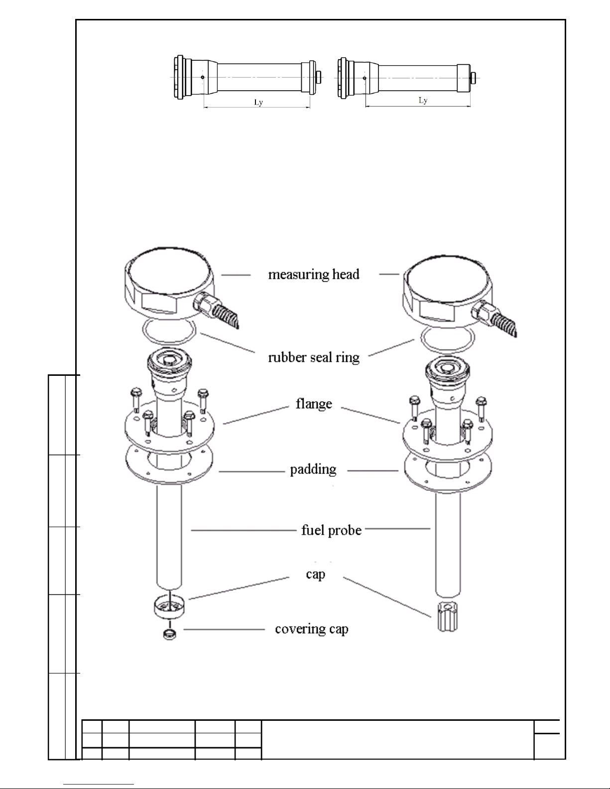
Fig.1.1
1.1.3. Contained parts.
1.1.3.1. Main contained parts.
The main contained parts are the probing device and attached detecting head, which
is fixed to FS tank surface with flange (Fig 1.2).
Fig.1.2. General view of FLS with string central contact (left) and pluggable central
contact (right).
1.1.3.2. Product designation and brief summary of the model range
Page 8
Copy Size А4
Page
EN.000 RE
8
Chg.
Page
Doc. #
Sign.
Date
Sign. and date
Rep. t
ag #
Inst. of t
ag #
Sign. and date
а
Script t
ag #
There are different identification marks of sensor, depending on the interface type,
measuring liquid dielectric permittivity, presence of tilt meter, probing device type
and length.
Fig. 1.3.
Epsilon EN2" – provides data exchange by RS-232 interface. "Epsilon EN4" provides data exchange by RS-485 interface.
"Epsilon EN6" – has two independent interfaces: RS-232 and RS-485. This sensor
is able to be a data concentrator for other FLS.
"Epsilon EZ6" – is operated only together with spark protection unit BIZ-EZ. Spark
protection unit BIZ-EZ - provides explosion protection of sensor model "EZ" and
data exchange by RS-232 and RS-485 interfaces.
1.1.3.3 Sensor identification to order.
1.1.3.3.1 Sensor identification contains of:
Designation;
space
- absent
i
- presence of tilt meter
m
- data processing considering
tank models
E Х 6 R i m - H 075
Identification of
measuring head
Identification
of fuel probe
Model
Interface type
2
- RS-232
4
6
- RS-232+RS-485
8
- CAN
For measurement
of liquids
dielectric
permittivity
space
- from 1.5 to 3.3
R
- from 1.5 to 5
operational characteristics
and combinations
Fuel probe design
space
- string
H
- pluggable
Fuel probe length (cm)
EN
EZ
Page 9

Copy Size А4
Page
EN.000 RE
9
Chg.
Page
Doc. #
Sign.
Date
Sign. and date
Rep. t
ag #
Inst. of t
ag #
Sign. and date
а
Script t
ag #
Sensor type - "Epsilon"
Model designation;
Interface type;
Relative electric permittivity range of values for operating fluids;
Operational characteristics
Modification of fuel probe;
Fuel probe length (cm);
Identification of these specifications.
Page 10

Copy Size А4
Page
EN.000 RE
10
Chg.
Page
Doc. #
Sign.
Date
Sign. and date
Rep. t
ag #
Inst. of t
ag #
Sign. and date
а
Script t
ag #
1.1.3.3.2 Example of "Epsilon" sensors’ identification recording when
ordering and in documentation of other products, where it can be applied:
Fuel level sensor
"Epsilon" EN6Ri-H075 TOR U30466754-07:2013,
where:
- " Fuel level sensor"– item;
- "Epsilon" – name;
- "EN" – model;
- "6" – RS-232 and RS-485 interfaces;
- "R" – for measuring in a liquid with dielectric permittivity between 1.5
and 5;
- "i" – presence of an inclinometer;
- "-" – separator character in an identification;
- "H" – plug-in probe;
- "075" – probe length is 75 cm;
1.1.3.3.3 Probe length determination when ordering (see fig. 1.4)
Required length of the probe is determined by formula
L of probe = extern. L of tank – ∆, where:
L of probe – length of probe upon ordering (see fig. 1.5, 1.6);
extern. L of tank – external height of tank in the place of sensor
installation;
∆ – size of gap between the probe and the bottom of the tank.
Recommended values of the gap:
- ∆ = 10…20 mm – for hard metallic tanks (higher elevation of the tank must
comply with higher value of gap);
- ∆ = 30 mm – for hard tanks having insufficient rigidity (such as plastic
tanks of considerable height).
Page 11

Copy Size А4
Page
EN.000 RE
11
Chg.
Page
Doc. #
Sign.
Date
Sign. and date
Rep. t
ag #
Inst. of t
ag #
Sign. and date
а
Script t
ag #
Fig. 1.4 Probe length determination when ordering
Fig. 1.5 Probe with a string
Fig. 1.6 Probe with plug contact
It is recommended to use the probes having lengths, standardized by
manufacturer (see table 1.1) – this will eliminate additional works during
sensor installing or replacing.
22
L зонда
22
L зонда
Flange
Ext. L of tank
L of probe
L of probe
L of probe
Page 12
Copy Size А4
Page
EN.000 RE
12
Chg.
Page
Doc. #
Sign.
Date
Sign. and date
Rep. t
ag #
Inst. of t
ag #
Sign. and date
а
Script t
ag #
Thus, for example, overall height of the tank semi-trailer tractors of such
widespread brands as DAF, MAN, Renault, Scania is 620 mm – it is necessary to
apply the sensor with 600 mm long probe for them.
Sensor manufacturer provides the following set of standardized lengths of
probes (Table 1.1)
Table 1.1
Recommended length
of the probe
Typical vehicle models
800
Special vehicles
600
Semitrailer tractors DAF, IVECO, MAN,
Mercedes-Benz, Renault, Scania etc., technique
on their platform.
510
KAMAZ, KrAZ trucks, technique on their
platform
420
MAZ trucks, technique on their platform
340
ZIL trucks
250
Light commercial vehicle, minibuses
In case if data on the length in the record is absent, measuring probe is
typically supplied 750 mm long.
Page 13

Copy Size А4
Page
EN.000 RE
13
Chg.
Page
Doc. #
Sign.
Date
Sign. and date
Rep. t
ag #
Inst. of t
ag #
Sign. and date
а
Script t
ag #
1.1.3.4 Delivery package
1.1.3.4.1 Basic delivery package
Table 1.2
Name
Models
Quantity,
pcs.
Notes
1
2
3
4
Measuring head
EN, EZ
1
Probe
EN, EZ
1
Flange
EN, EZ
1
Rubber seal ring
EN, EZ
1
Support of the probe
EN, EZ
1
Socket plug cap
EN
1
Self-drilling helical screw
EN, EZ
4
Ø 4.2х19 mm
Self-drilling helical screw
EZ
2
Ø 3.9х16 mm
Self-drilling helical screw for
sealing
EN, EZ
1
Ø 4.2х19, stainless, with an
aperture for sealing
Tamper-evident seal
EN
2
With wire for sealing
EZ
4
Interface cable EN2
EN2,
EN4
1
Length 7.5 m
Interface cable EN6
EN6
1
Length 7.5 m
Interface cable EZ
EZ
1
Length up to 300 m
manufactured upon request
Interface cable BIZ
EZ
1
Length 1.0 m
Cable tightening
EN, EZ
15
200х3.6 mm
Spark protection module BIZEZ
EZ
1
Grounding wire
EZ
1
Length 1 m
String
EN, EZ
with
string
1
SPTA
Page 14

Copy Size А4
Page
EN.000 RE
14
Chg.
Page
Doc. #
Sign.
Date
Sign. and date
Rep. t
ag #
Inst. of t
ag #
Sign. and date
а
Script t
ag #
end of Table 1.2
1
2
3
4
Fuse strip 0.1 А 250V
EN
1
Ø 5х20 mm, quick-action
Fuse strip 0.5 А 250V
EZ
1
Ø 5х20 mm, quick-action
Insertion label
EN, EZ
with
string
1
Scheme of string fixing
Vehicular safety appliance 1А
EZ
1
1.1.3.4.2 Additional accessories
Table 1.3
Name
Indication
Quantity
Notes
Socket plug
IEC EN C.100
1
Installed on the tank after
complete dismantling of the
sensor
Socket plug-cover
IEC EN. 002.0
1
Installed on the tank after
removal of the measuring
head
EX2 cable for
connecting a
sensor to PC
IEC ES С.100
1
For models EN2
Supplied upon additional
request
EX4 cable for
connecting a
sensor to PC
IEC ES С.100-
01
1
For models EN4
Supplied upon additional
request
EX6 cable for
connecting a
sensor to PC
IEC EN СА.100
1
For models EN6, EZ6
Supplied upon additional
request
CD-ROM with
software
EN.000 CD1
1
Supplied upon additional
request
Page 15

Copy Size А4
Page
EN.000 RE
15
Chg.
Page
Doc. #
Sign.
Date
Sign. and date
Rep. t
ag #
Inst. of t
ag #
Sign. and date
а
Script t
ag #
1.1.3.4.2 Operation documentation
Table 1.4
Name
Identification
Q-ty
Notes
Passport
EN.000 ПС 1 For model EN
Passport
EZ.000 ПС 1 For model EZ
Passport
BIZ-EZ.000 ПС
1
For spark protection module
Operation manual
EN.000 РЕ
1
1 copy per batch on a single
address
Installation
manual
EN.000 ИМ
1
Supplied upon additional request
1.1.4 Structure and Functioning
Measuring of fuel level is carried out by measuring head together with
probe immersed into the fuel.
When immersed into the fuel, probe of sensor performs the function of a
variable capacitor whose capacitance is linearly dependent on the filling level of
fuel.
Sensor’s measuring head performs a linear transformation of probe's
capacitance into a digital code of the fuel level, processing of obtained digital data
with averaging the measurement results, measurement of head’s temperature
and data output in unified EDE Protocol via RS-485 or RS-232 interface. Fuel level
data is outputted in form of 16-bit value, and optionally as 10- or 12-bit value
selectable, data about the temperature – in the form of 8-bit value. In order to
estimate acceleration and angle of vehicle's inclination, for purpose of estimation
of reliability of level value and its further compensation depending on the angle,
there is the inclinometer built in the head.
In order to define volume of controlled fuel, the procedure of the fuel tank
calibration should be performed, at which dependence between the volume of
fuel and level code is determined.
Calibration procedure control and establishing data exchange parameters
by means of "eS Install" software are described in Appendix А to the document
"EN.000 ИМ. Installation manual ".
EDE data exchange protocol is given in Appendix B of that document.
The embedded software update process, as well as saving and restoration
process of configuration data is described in Appendix C of that document.
Page 16

Copy Size А4
Page
EN.000 RE
16
Chg.
Page
Doc. #
Sign.
Date
Sign. and date
Rep. t
ag #
Inst. of t
ag #
Sign. and date
а
Script t
ag #
1.1.5 Labeling and Sealing
1.1.5.1 Labeling
1.1.5.1.1 Labeling of measuring head:
- name and label for goods and services of the enterprisemanufacturer;
- name and conventional identification;
- explosion-proofing labeling;
- operational temperature range;
- serial (factory) number according to the system of enterprise-
manufacturer.
1.1.5.1.2 Labeling of spark protection module (for "EZ" models):
- name and label for goods and services of the enterprise-
manufacturer;
- name and conventional identification;
- explosion-proofing labeling;
- operational temperature range;
- lettering "Intrinsically safe circuits";
- serial (factory) number according to the system of enterprise-
manufacturer.
1.1.5.1.3 Labeling on sensor packaging:
- name and label for goods and services of the enterprisemanufacturer;
- name and conventional identification;
- production date (month, year);
- explosion-proofing labeling (for "EZ" model);
- type and length of the probe;
- operational temperature range;
- TOR number, according to which sensor is manufactured;
- lettering "Made in Ukraine";
- serial (factory) number in Arabic numerals;
- serial (factory) number in the form of barcode.
1.1.5.2 Sealing
In order to protect sensor and spark protection module against
unauthorized tampering, tamper-evident seals are installed.
One seal protects the measuring head from unscrewing, and the rest are installed
on separable interface cable connections.
Sealing procedure is described in section 4 of the document "EN.000 ИМ.
Installation manual".
Page 17

Copy Size А4
Page
EN.000 RE
17
Chg.
Page
Doc. #
Sign.
Date
Sign. and date
Rep. t
ag #
Inst. of t
ag #
Sign. and date
а
Script t
ag #
1.1.6 Packing
Measuring head with attached probe is packed in polyethylene "sleeve" and
building kit from basic delivery package (see table 1.2) and spark protection
module (for models "EZ"), are packed in sealed polyethylene packages.
Page 18

Copy Size А4
Page
EN.000 RE
18
Chg.
Page
Doc. #
Sign.
Date
Sign. and date
Rep. t
ag #
Inst. of t
ag #
Sign. and date
а
Script t
ag #
1.2 Description of product components
1.2.1 Measuring heads
Sensor’s measuring head (fig. 1.2) contains:
- capacitometer;
- inclinometer (in certain models);
- data concentrator with calibration tables;
- digital data processing circuit;
- data exchange device;
- galvanic barrier (for model EN);
- power stabilizer and scheme providing necessary protection of input
and output circuits.
Connection with external devices is provided through interface cable.
Capacitometer performs the conversion of current capacity of the probe
into digital code. Conversion is a linear function with variable parameters.
Inclinometer is present in the models of EXХXiх-XXXX version. Inclinometer
is executed on the basis of accelerometer with high resolution, and designed for
evaluation of acceleration and inclination angle of the vehicle, in order to estimate
reliability of the fuel level value and for possibility of its consequent compensation
depending on inclination angle.
Built-in data concentrator features in all listed models, however, using it
together with other sensors is possible only with EN6 model due to the presence
of two independent interfaces RS-232 and RS-485. Designation of master and
slave ports is set programmatically. Other models may only use embedded
calibration tables on the eigenvalues.
Digital data processing circuit performs control of capacitance meter (range,
zero offset, etc.) as well as temperature compensation, filtering and scaling the
obtained data. Data exchange device allows data exchange with the monitoring
device, saving / loading of calibration and configuration data of fuel level sensor,
remote upgrade of built-in software via serial interface.
Built-in galvanic isolation is an additional instrument fuel level sensor safety
system, and it is designed for isolation of measuring element’s and probe’s circuits
from the rest of electronics of the head.
This solution eliminates the possibility of passage interference currents on
circuits "case – signal ground”, increases interference immunity of measuring
element, enhances stability and reliability of the entire device.
For EZ model galvanic barrier is realized in spark protection module BIZ-EZ.
The measuring head is attached to the probe by means of a threaded
connection. Tightness of measuring head's attachment is provided by sealing ring
located in the end groove.
1.2.2 Probe
Page 19

Copy Size А4
Page
EN.000 RE
19
Chg.
Page
Doc. #
Sign.
Date
Sign. and date
Rep. t
ag #
Inst. of t
ag #
Sign. and date
а
Script t
ag #
The probe is a coaxial capacitor formed by a pipe made of aluminum alloy
(outer electrode) and an insulated copper string or aluminum alloy pin (inner
electrode). Required string tension is supported by a spring that is located in
contact of the probe’s connector. Concentricity of a pin and an outer pipe is
provided by internal plastic inserts.
1.2.3 Spark protection module BIZ-EZ (for model "Epsilon EZ")
Intrinsic Safety Requirements for sensor of "EZ" model is provided by
connecting them via spark protection module, which is included in delivery
package.
Spark protection module is designed for power supply of the sensor with
type of explosion protection "intrinsically safe electrical circuit" of "ia" level, and
for exchange of information signals with a sensor via RS-485 interface. Spark
protection module has galvanic insulation both between inputs and outputs of
power supply, and between inputs and outputs of RS-485 interface.
Spark safety of electrical circuits of a unit, associated with equipment in
potentially explosive area, is provided by current and voltage limiting in electrical
circuits down to intrinsically safe values.
Spark protection module is designed for installation beyond the potentially
explosive areas. It relates to an apparatus of active type and is designed for the
protection of intrinsically safe circuits under the influence of a voltage up to
250 V.
Power supply of spark protection module is carried out from the source of
direct current with voltage of 9...36 V. Parameter values of intrinsically safe
circuits of spark protection module are given in Table 2.2.
1.2.4 Flange
Flange serves for hermetic fixing of the probe to the tank of vehicle. Fixation
of flange to the tank is realized by means of self-drilling screws. Tight seal
between tank and flange is provided by a rubber gasket.
1.2.5 Interface cable
Interface cable is designed for connecting measuring head to external
devices. Interface cable is protected against mechanical impacts with flexible
metal hose or corrugated pipe.
Page 20

Copy Size А4
Page
EN.000 RE
20
Chg.
Page
Doc. #
Sign.
Date
Sign. and date
Rep. t
ag #
Inst. of t
ag #
Sign. and date
а
Script t
ag #
2 INTENDED USAGE
2.1 Operating restrictions
2.1.1 During operation of the sensor it is prohibited:
– to use the device inappropriately;
– to connect the sensors to devices, whose interface does not meet the
specifications indicated in this manual;
– to expose device to the impact of aggressive media;
– to supply power, exceeding the limit value of 36 V;
– to allow exposure to pulsed voltage on power circuits with values greater
than the values listed in the Table 1.1.
2.1.2 Using an item with fluids, preserving their aggregate state in the
operating temperature range, is allowed.
2.1.3 Dielectric permeability measured liquid should correspond to liquid
permeability, applied when calibrating. Failure to observe this results in an
increase in measuring errors.
2.2. Explosive safety
2.2.1 EN model sensors are explosion proof, have "1ExsiaIICT6 Х" explosion
proof mark and can be used in Class 1 and 2 explosion-hazardous areas – head,
and 0, 1, 2 – probe. Sign "Х" in explosion proofing labeling indicates specific
conditions of sensors’ safe application, lies in the following:
- sensors should be included in the electrical circuits of equipment, powered
only from the vehicle battery with a voltage not exceeding 36 V, and having
no electrical connections with electrical equipment which has other sources
of power;
- connection of sensors to the mains must be carried out via a fuse with a
nominal value of not more than 0.1 A.
EZ model sensors are explosion proof, have explosion proofing labeling "0
Ex ia IIВ T6" and can be used in Class 0, 1 and 2 explosion-hazardous areas.
Explosion proofing of EZ model sensor is provided by its connection via
spark protection module BIZ-EZ.
Page 21

Copy Size А4
Page
EN.000 RE
21
Chg.
Page
Doc. #
Sign.
Date
Sign. and date
Rep. t
ag #
Inst. of t
ag #
Sign. and date
а
Script t
ag #
Table 2.1 Parameter values of intrinsically safe field circuits of model EZ sensor:
Name of feature or parameter
Meas.
unit
Value
Maximum input voltage, U0
V
8.0
Maximum input current, I
0
mA
100
Maximum internal capacitance, C
0
mfd
80
Maximum internal inductance, L
0
mH
0.2
2.2.2 Spark protection module "BIZ-EZ" has explosion proofing labelling
"ExiaIIВ" and can only be installed in explosion safe area.
Table 2.2 Parameter values of intrinsically safe field circuits of spark protection
module
Name of feature or parameter
Meas.
unit
Value
Maximum input voltage, U0
V
8.0
Maximum input current, I
0
mA
450
Maximum internal capacitance, C
0
mfd
80
Maximum internal inductance, L
0
mH
0.5
* - maximum values of L0, C0 spark protection module are established
considering 1.5-tuple safety factor
2.3 Preparation for use
Preparation of item for use is performed in accordance with "EN.000 ИМ
Installation manual".
Page 22
Copy Size А4
Page
EN.000 RE
22
Chg.
Page
Doc. #
Sign.
Date
Sign. and date
Rep. t
ag #
Inst. of t
ag #
Sign. and date
а
Script t
ag #
2.4 Item application
2.4.1 Application of a sensor consists in obtaining electronic information on
the fuel level in tank from it by external device (such as onboard controller).
Sensor control is performed by external device via interface cable and does not
require any additional operator's intervention.
2.4.2 The list of possible malfunctions and their solutions
Table 2.1
Malfunction
Troubleshooting
Sensor transmits the data about the
maximum level of fuel in tank,
although the actual level of fuel is less
than the maximum value
Check the tank for the presence of
conductive liquid (water) and drain it
at presence
Sensor stopped transmitting data
about the level of fuel in the tank
Consult your authorized dealer or
manufacturer with request to replace
the measuring sensor head or the
complete set of sensor
2.4.3 Operation in extreme conditions
In case of fire, having occurred in the location of sensor, you must
disconnect onboard power supply and perform all standard procedures for
extinguishing fire in the vehicle.
Page 23

Copy Size А4
Page
EN.000 RE
23
Chg.
Page
Doc. #
Sign.
Date
Sign. and date
Rep. t
ag #
Inst. of t
ag #
Sign. and date
а
Script t
ag #
3 MAINTENANCE
3.1 Item Maintenance
3.1.1 General guidelines
3.1.1.1 Sensor is a maintenance-free product, but if vehicle
maintenance regulation provides procedure of fuel tank prophylaxis, then
it is advisable to simultaneously perform preventive maintenance of sensor
as well.
Spark protection module is subject to examination at least once every
6 months (see 3.1.3.2).
3.1.1.2 Only personnel who are familiar with this operating manual and
the document "EN.000 ИМ. Installation manual" is admitted to sensor
maintenance.
3.1.2 Safety measures
3.1.2.1 During maintenance of fuel level sensor, organizational and technical
measures, providing safe operation of control and measuring equipment,
auxiliary equipment and consumables.
3.1.2.2 Responsibility for the implementation of security measures is
imposed on the technical staff carrying out the installation of fuel level sensor, as
well as on the personnel responsible for equipment of the work site.
3.1.2.3 Requirements of fire safety rules, acting on the territory of consumer,
must be observed on the work site.
3.1.2.4 Requirements of occupational safety regulations in accordance with
those, acting on customer’s site, must be observed on the vehicles on the work site
of sensor installation.
Page 24

Copy Size А4
Page
EN.000 RE
24
Chg.
Page
Doc. #
Sign.
Date
Sign. and date
Rep. t
ag #
Inst. of t
ag #
Sign. and date
а
Script t
ag #
3.1.3 Order of item maintenance
3.1.3.1 Sensor maintenance
Complete dismantling of sensor must be performed in the following
consequence (fig. 3.1):
- to disconnect interface and connecting cable;
- to unscrew and remove measuring head, after that to unscrew sensor probe
from the flange;
- to close an aperture of flange with socket plug IEC EN C. 100 (see Table 1.3),
as shown in fig. 3.1;
Fig. 3.1 Complete dismantling of fuel level sensor and installing socket plug
- to wash entire part of probe with fuel (with which the sensor is
opertated) and to blow with compressed air;
- to control own parameters of the measuring head (using "eS Install"
software, according to procedure, described in appendix А of the
document "EN.000 ИМ. Installation manual ");
- to perform installation and sealing of the sensor according to
requirements 1.1.5.2.
3.1.3.2 Maintenance of Spark Protection Module
Maintenance of spark protection module consists in its examination and
elimination of violations during the operation.
During examination it is necessary to perform the following operations:
- to inspect the case and to identify mechanical damage;
- to clean the case of spark protection module from dust and dirt;
- to check labeling;
- to check the attachment of module;
Page 25

Copy Size А4
Page
EN.000 RE
25
Chg.
Page
Doc. #
Sign.
Date
Sign. and date
Rep. t
ag #
Inst. of t
ag #
Sign. and date
а
Script t
ag #
- to check the quality electrical connection to the ground bus or to a vehicle
body;
- to check the quality of connection of external circuits;
- to check the integrity of protective seals.
In case of detecting damages it is necessary to eliminate them, and if it is
impossible to correct problems, to carry out the replacement of damaged parts.
It is forbidden to operate spark protection module with damages and
malfunctions, as well as its repair.
In case if it becomes necessary to disassemble spark protection module,
disassembling should be performed in the following consequence:
- to disconnect the power connector (from BIZ interface cable);
- to disconnect intrinsically safe circuit connector (from EZ interface cable);
- to disconnect the ground wire of spark protection module casing from
grounding bus terminal or vehicle body;
- to remove spark protection module from place of installation.
Page 26

Copy Size А4
Page
EN.000 RE
26
Chg.
Page
Doc. #
Sign.
Date
Sign. and date
Rep. t
ag #
Inst. of t
ag #
Sign. and date
а
Script t
ag #
4 TEMPORARY REPAIR
4.1 Item temporary repair
4.1.1 General guidelines
4.1.1.1 Temporary item repair can be carried out only regarding
replacement of the measuring head. Sensor’s measuring head itself is nonrepairable item, and during guaranteed service life it retains stability of its
parameters.
4.1.1.1 Only personnel who are familiar with this operation manual and
with document "EN.000 ИМ. Installation instruction" is admitted to performance
of works.
4.1.1.3 Safety precautions during measuring head replacement are
similar to those during sensor maintenance (see 3.1.2)
4.2 Temporary repair of item components
4.2.1 Repair (replacement) of measuring head
4.2.1.1 In case of measuring head failure, and if vehicle operation before
installing another measuring head, it is necessary to make partial disassembling
of sensor.
4.2.1.1.1 Partial disassembling of sensor should be performed in the
following consequence (fig. 4.1):
- to disconnect the interface and connecting cables.
- to unscrew and remove the measuring head of sensor.
- if necessary, partially to screw on sleeve bearing of sensor probe into the
flange, as shown on fig. 4.1.
- to close sleeve bearing of sensor probe with cover-plug IEC EN. 002.0
(see table 1.3);
Page 27

Copy Size А4
Page
EN.000 RE
27
Chg.
Page
Doc. #
Sign.
Date
Sign. and date
Rep. t
ag #
Inst. of t
ag #
Sign. and date
а
Script t
ag #
Fig. 4.1 Partial disassembling of fuel level sensor и and installation of cover-
plug
- to upload new configuration data in new measuring head (see appendix В
of the document "EN.000 ИМ. Installation manual");
- to install and connect new measuring head, to perform sensor sealing
according to requirements of 1.1.5.2.
4.2.1.2 In case if configuration data was lost, it is necessary to perform
operations on sensor configuration, described in appendix В of the document
"EN.000 ИМ. Installation manual". If configuration data was successfully restored,
then re-calibration of the tank is not required.
4.2.2 Probe string replacement
If it is necessary to replace the string, the following operations should be
performed:
- To disconnect measuring head from the probe, having performed
operations, described in the relevant section of the document "EN.000 ИМ.
Installation manual " in reverse order;
- To disconnect the string in lower part of the probe, having removed plug-
cap, and in the upper part of probe, as shown on fig. 4.3;
Page 28

Copy Size А4
Page
EN.000 RE
28
Chg.
Page
Doc. #
Sign.
Date
Sign. and date
Rep. t
ag #
Inst. of t
ag #
Sign. and date
а
Script t
ag #
Fig. 4.3 Disassembling of string
- Install the string, having performed the operations, described in subsection
8.3 of the document "EN.000 ИМ. Installation manual" in reverse order.
Page 29

Copy Size А4
Page
EN.000 RE
29
Chg.
Page
Doc. #
Sign.
Date
Sign. and date
Rep. t
ag #
Inst. of t
ag #
Sign. and date
а
Script t
ag #
5 TRANSPORTATION AND STORAGE
Transportation of sensor in transport packaging of enterprisemanufacturer is allowed by all types of closed land and maritime transport (in
railway waggons, containers, covered trucks, holds, etc.).
Transportation in pressurized heated compartments of aircraft is allowed.
During transportation and storage, requirements of manipulation signs,
printed on group transport packaging, should be respected.
 Loading...