

Page 1

The ETL Symbol is a UK registered certification mark of the
Department of Energy and Climate Change
Authorised User: 03195
Installation & User Guide
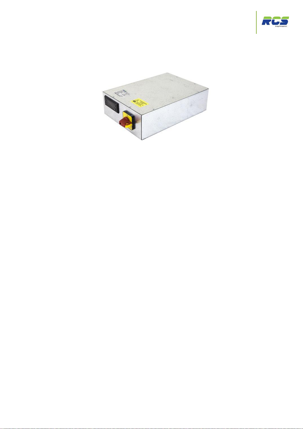
Eden Power Tray
Installation Guide | Issue 2.0 | The Eden Power Tray Page 1
Page 2

Contents
The Eden Power Tray
Contents
1. INTRODUCTION 4
1.1 The Eden Power Tray Range 4
1.1.1 Variants / Part Codes for Ordering 5
1.1.2 Replacing Legacy Equipment 6
1.1.3 Eden Power Tray – Mating Connectors 6
2. CONNECTION DETAILS 7
2.1 EP3115 & 3116 10A Assisted Defrost / Major Tray Connectivity 7
2.2 EP3115 & 3116 10A Assisted Defrost / Major Tray Circuit Diagram 8
2.3 EP3113 & 3114 30A Assisted Defrost / KTUC09Tray Connectivity 9
2.4 EP3113 & 3114 30A Assisted Defrost / KTUC09Tray Circuit Diagram 10
2.5 EP3119 & 31110 Hot Gas Defrost / KTUC09 HG Tray Connectivity 11
2.6 EP3119 / 31110 Hot Gas Defrost / KTUC09 HG Tray Circuit Diagram 12
2.7 EP3117 & EP3118 External Defrost Contactor / KTUC09 Tray Connectivity 13
2.8 EP3117 & EP3118 External Defrost Contactor / KTUC09 Tray Circuit Diagram 14
2.9 EP3111 Minor Assisted Defrost Tray Connectivity 15
2.10 EP3111 Minor Assisted Defrost Tray Circuit Diagram 16
2.11 EP3110 & 3112 Off-Cycle Defrost Tray Connectivity 17
2.12 EP3110 & 3112 Off-Cycle Defrost Tray Circuit Diagram 18
2.13 All Variants – Sensor / Communication Network Connections 19
2.14 All Variants – Tray End View 20
3. SETTING THE CONTROLLER UP 21
3.1 Front panel display keys & icons 21
3.2 Using the front panel display & function keys 23
3.2.1 Set up menu 24
3.2.2 Controllers address & communications menu 26
3.2.3 Controllers refrigeration related parameter menu 28
3.2.4 Controllers defrost menu 30
3.2.5 Controllers fan related parameter menu 32
3.2.6 Controllers times related parameter menu 34
3.2.7 Controllers current status menu 36
3.2.8 Controllers current alarms menu 38
3.2.9 Controllers lights related parameter menu 40
3.2.10 Controllers sleep mode menu 41
3.2.11 Controllers self test menu 42
4. CLEANING INSTRUCTIONS 43
5. SPECIFICATION 44
5.1 Power requirements 44
5.2 Dimensions 44
5.3 Inputs 44
5.4 Communications 44
Installation Guide | Issue 2.0 | The Eden Power Tray Page 2
Page 3

Contents
The Eden Power Tray
6. REVISION HISTORY 45
7. DISCLAIMER 46
8. CONTACT DETAILS 47
9. APPENDICES 48
9.1 Cycle Time function (Times menu (Ti13) ` 48
9.2 Defrost Cycle (Fans Off) 49
9.3 Defrost Cycle (Fans On) 50
9.4 Integral Compressor Action 51
9.5 Remote Display 52
9.5.1 Panel Cut-out 52
9.5.2 Remote Display 53
9.5.3 Retaining Clips 53
9.5.4 Remote Display Module 53
10. EUROPEAN DECLARATION OF CONFORMITY 54
Installation Guide | Issue 2.0 | The Eden Power Tray Page 3
Page 4
Introduction
The Eden Power Tray
1. Introduction
The Eden Power Tray series of products are a range of complete refrigerated cabinet control solutions.
The extensive range provides prewired control panels suitable for both new installations and
replacement of legacy products. All of which utilise the intuitive RCS Eden Compact controller.
Each of the variants in the range delivers a powerful combination of connectivity, flexibility and ease of use in a
gear tray capable of safely supplying all required cabinet loads.
The Eden Power Tray range offers quality, high performance case control which will encompass and satisfy the
most stringent of refrigerated cabinet applications.
1.1 The Eden power Tray Range
All high current outputs are protected by re-settable MCB’s. Connector configurations where possible remain
identical to previous RCS cabinet control panels to safeguard easy replacement of legacy units. The assisted
defrost variants also provide an external connection for defrost heater klixons to provide further safety features.
The Eden Compact controller incorporated into each of the power tray variants was designed as the first all-inone compact refrigeration controller requiring no additional communication modules. The Eden Compact provides
easy configuration and the ability to set custom parameter sets.
The Eden Compact series covers the full range of evaporator inlet valve type and network connectivity options.
The user must choose at the point of ordering which of the following two basic options are required:-
Network compatibility
IP
RS485
Inlet Valve Type
LSV
EEV
Each model is easy to install and configure, thanks to features such as the standard two-part connectors for all
external wiring of Inputs/Outputs. All Eden Compact controllers provide the option of up to seven temperature /
analogue inputs for maximum flexibility, and multiple sensor types are also supported. (NB sensor types cannot
be mixed on a single controller).
Installation Guide | Issue 2.0 | The Eden Power Tray Page 4
Page 5

Part Codes
The Eden Power Tray
Variant
Inlet Valve Type
Communication Type
Part No
Off-Cycle defrost
LSV
RS485
EP3110
Off-Cycle defrost
EEV
RS485
EP3112
Off-Cycle defrost
LSV
IP
EP3120
Off-Cycle defrost
EEV
IP
EP3122
10A Assisted defrost
LSV
RS485
EP3115
10A Assisted defrost
EEV
RS485
EP3116
10A Assisted defrost
LSV
IP
EP3125
10A Assisted defrost
EEV
IP
EP3126
30A Assisted defrost
LSV
RS485
EP3113
30A Assisted defrost
EEV
RS485
EP3114
30A Assisted defrost
LSV
IP
EP3123
30A Assisted defrost
EEV
IP
EP3124
External Defrost contactor
LSV
RS485
EP3117
External Defrost contactor
EEV
RS485
EP3118
External Defrost contactor
LSV
IP
EP3127
External Defrost contactor
EEV
IP
EP3128
Hot Gas defrost
LSV
RS485
EP3119
Hot Gas defrost
EEV
RS485
EP31110
Hot Gas defrost
LSV
IP
EP3129
Hot Gas defrost
EEV
IP
EP31210
1.1.1 Variants / Part Codes for Ordering
This installation and set-up guide covers the complete Eden Power Tray range. The following part codes should
be used at the ordering stage:-
Remote display variants of each of the above are also available.
Please refer to each of the connection details and circuit drawings within this document to establish maximum
ratings for outputs for each variant.
Please note that warranty is void if any Eden power tray is used in any application that does not conform to the
tray specification.
Installation Guide | Issue 2.0 | The Eden Power Tray Page 5
Page 6

Legacy Part Codes
The Eden Power Tray
Part Number
Replacement For
EP3115 (LSV)
Major Assisted Defrost
EP3116 (EEV)
Major Assisted Defrost
EP3113 (LSV)
KTUC09 Assisted Defrost (Electric)
EP3114 (EEV)
KTUC09 Assisted Defrost (Electric)
EP3119 (LSV)
KTUC09 Hot Gas Defrost
EP31110 (EEV)
KTUC09 Hot Gas Defrost
EP3117 (LSV)
KTUC09 Tray (External Contactor)
EP3118 (EEV)
KTUC09 Tray (External Contactor)
EP3111 (LSV Only)
Minor Assisted Defrost
EP3110 (LSV)
Off-Cycle Defrost - ALL VARIANTS
EP3112 (EEV)
Off-Cycle Defrost – ALL VARIANTS
1.1.2 Replacing Legacy Equipment
The following part codes should be used at the ordering stage when replacing previous Powertray models:
1.1.3 Power Tray Mating Connectors
Eden Power Tray Mating Connectors:-
Incoming Mains Supply Connector, mates with: Weidmuller STVS3 161699 RCS Part Code KS3STVS00
Cable Clamp / Strain Relief for above connector: Weidmuller STVS3ZE 161387. RCS Part Code K00STV3ZE
STV1 / 2, mates with: Weidmuller STVS3 174367. RCS Part Code KP10STVS00
Cable Clamp / Strain Relief for above connector: weidmuller STVS10ZE 161394. RCS Part Code K010STV10ZE
Sensor / 485 Connector, mates with: Weidmuller BL12 126026 RCS Part Code KS12BL00
Klixon (Loop Back) RCS Part Code 300-00238
Installation Guide | Issue 2.0 | The Eden Power Tray Page 6
Page 7
Connection Details – 10A Assisted Defrost
The Eden Power Tray
2. Connection Details
Pin Number
Function
Rating/Designation
1
Earth
2 Defrost Live
10A Internal MCB (CB 2)
3
Defrost Neutral
4
LSV/EEV Live
2A Internal MCB (CB 8)
5
LSV/EEV Neutral
6
Fans Live
4A Internal MCB (CB 9)
7
Fans Neutral
8
Lights Live
6A Internal MCB (CB 5)
9
Lights Neutral
10
Earth
Pin Number
Function
Rating/Designation
1
Earth
2 Suction Live
2A Internal MCB (CB7)
3
Suction Neutral
4 Not Used
5 Not Used
6 Not Used
7
Not Used
8
Trim Heater Live
10A Internal MCB (CB 6)
9
Trim Heater Neutral
10
Earth
Pin Number
Function
Rating Designation
1 Unit Supplied with loop fitted
2
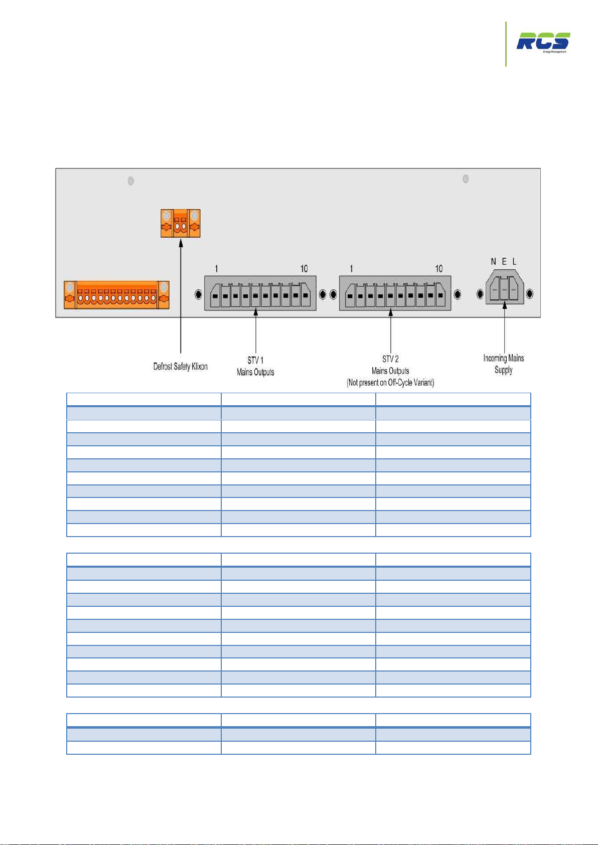
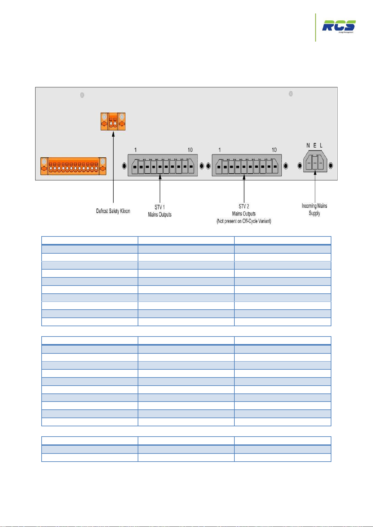
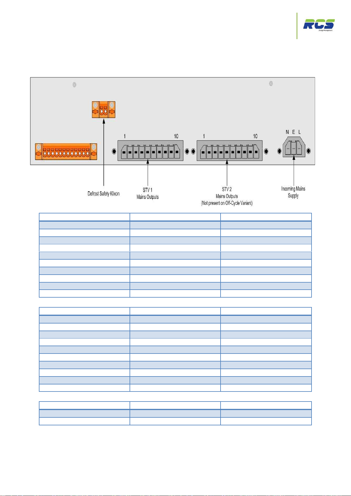
2.1 EP3115, EP3125 (LSV) & EP3116, EP3126 (EEV)
(10A Assisted Defrost & Major Legacy replacement) - Connectivity Details
STV1
STV2
Defrost Safety Klixon
Eden controller power is supplied via an internal 2A MCB (CB 1)
Installation Guide | Issue 2.0 | The Eden Power Tray Page 7
Page 8
10A Assisted Defrost Circuit Diagram
The Eden Power Tray
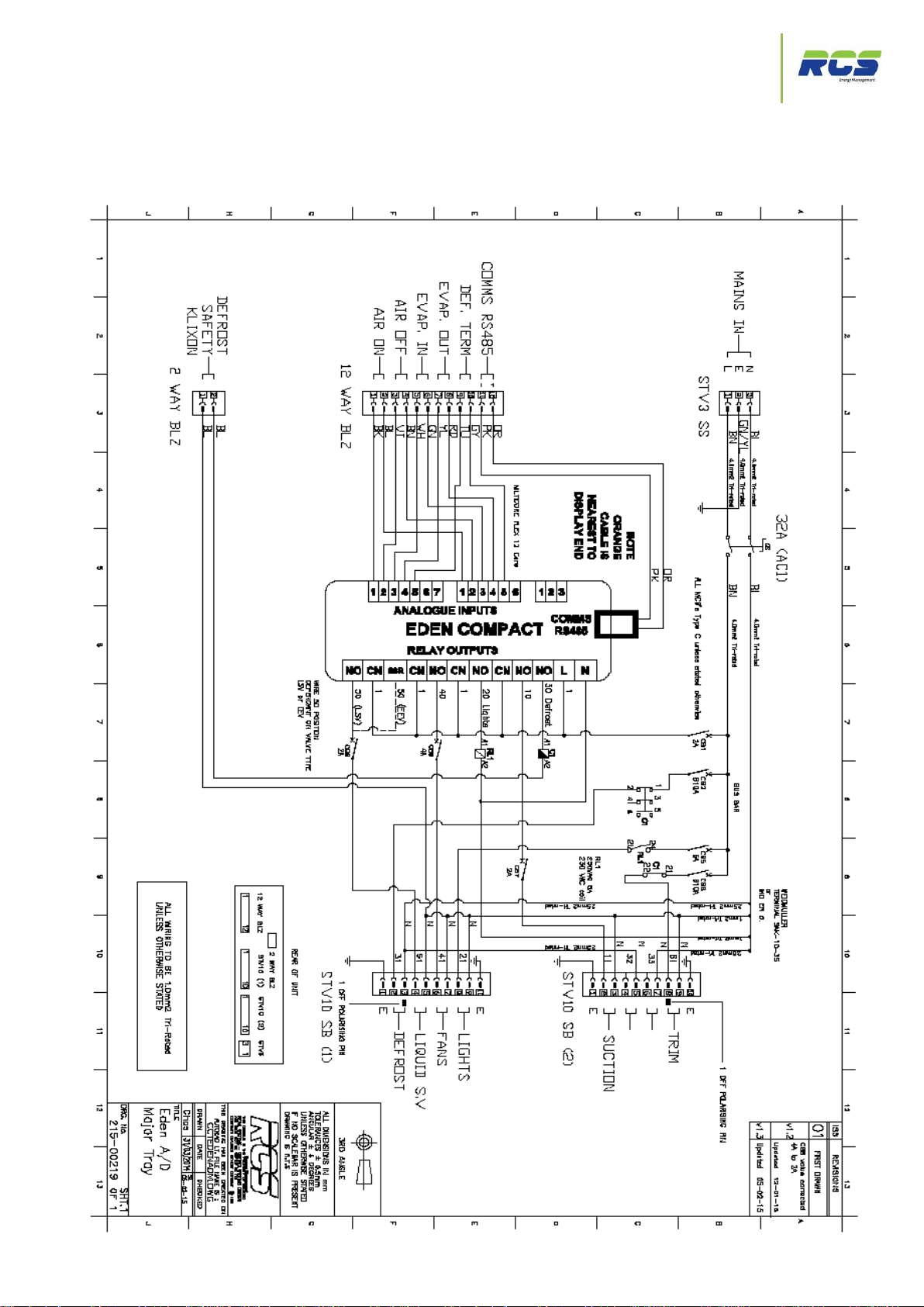
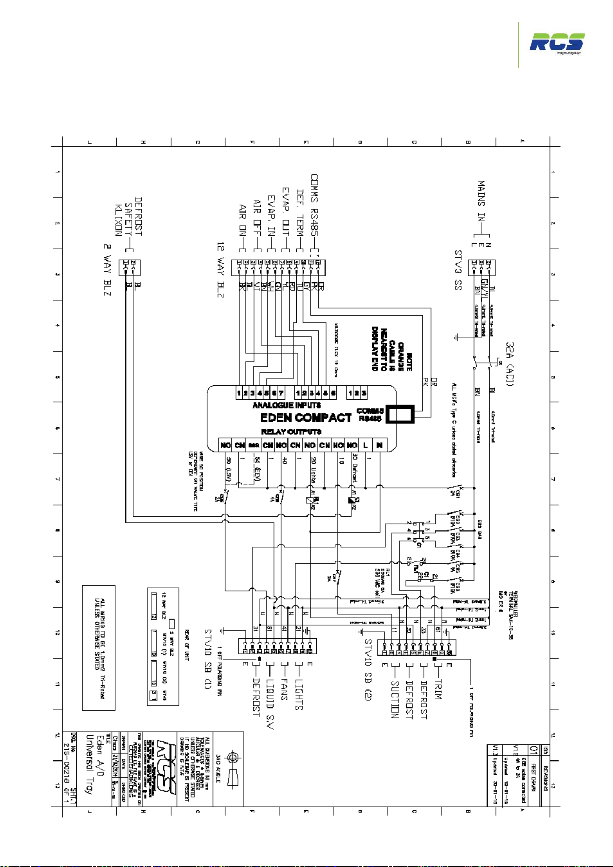
2.2 EP3115, EP3125 (LSV) & EP3116, EP3126 (EEV)
(10A Assisted Defrost & Major Legacy replacement) -Circuit Diagram
Installation Guide | Issue 2.0 | The Eden Power Tray Page 8
Page 9
Connection Details - 30A Assisted Defrost
The Eden Power Tray
2.3 EP3113, EP3123 (LSV) & EP3114, EP3124 (EEV)
Pin Number
Function
Rating/Designation
1
Earth
2
Defrost Live
10A Internal MCB (CB 2)
3
Defrost Neutral
4
LSV/EEV Live
2A Internal MCB (CB 8)
5
LSV/EEV Neutral
6
Fans Live
4A Internal MCB (CB 9)
7
Fans Neutral
8
Lights Live
6A Internal MCB (CB 5)
9
Lights Neutral
10
Earth
Pin Number
Function
Rating/Designation
1
Earth
2 Suction Live
2A Internal MCB (CB 7)
3
Suction Neutral
4 Defrost Live
10A Internal MCB (CB 3)
5
Defrost Neutral
6 Defrost Live
10A Internal MCB (CB 4)
7
Defrost Neutral
8
Trim Heater Live
10A Internal MCB (CB 6)
9
Trim Heater Neutral
10
Earth
Pin Number
Function
Rating Designation
1 Unit Supplied with loop fitted
2
(30A Assisted Defrost & KTUC09 Electric Defrost Legacy replacement) Connectivity Details
STV1
STV2
Defrost Safety Klixon
Eden controller power is supplied via an internal 2A MCB (CB 1)
Installation Guide | Issue 2.0 | The Eden Power Tray Page 9
Page 10
30A Assisted Defrost Circuit Diagram
The Eden Power Tray
2.4 EP3113, EP3123 (LSV) & EP3114, EP3124 (EEV)
(30A Assisted Defrost & KTUC09 Electric Defrost Legacy replacement) –
Circuit Diagram
Installation Guide | Issue 2.0 | The Eden Power Tray Page 10
Page 11
Connection Details - Hot Gas Defrost
The Eden Power Tray
2.5 EP3119, EP3129 (LSV) & EP31110, EP31210 (EEV)
Pin Number
Function
Rating/Designation
1
Earth
2
Not Used
3
Not Used
4
LSV/EEV Live
2A Internal MCB (CB 8)
5
LSV/EEV Neutral
6
Fans Live
4A Internal MCB (CB 9)
7
Fans Neutral
8
Lights Live
6A Internal MCB (CB 5)
9
Lights Neutral
10
Earth
Pin Number
Function
Rating/Designation
1
Earth
2 Suction Live
2A Internal MCB (CB 7)
3
Suction Neutral
4 Hot Gas S/V Live
2A Internal MCB (CB 3)
5
Hot Gas S/V Neutral
6
Not Used
7
Not Used
8
Trim Heater Live
10A Internal MCB (CB 6)
9
Trim Heater Neutral
10
Earth
Pin Number
Function
Rating Designation
1 Unit Supplied with loop fitted
2
(Hot Gas Defrost & KTUC09 Hot Gas Defrost Legacy replacement) Connectivity Details
STV1
STV2
Defrost Safety Klixon
Eden controller power is supplied via an internal 2A MCB (CB 1)
Installation Guide | Issue 2.0 | The Eden Power Tray Page 11
Page 12
Hot Gas Defrost Circuit Diagram
The Eden Power Tray
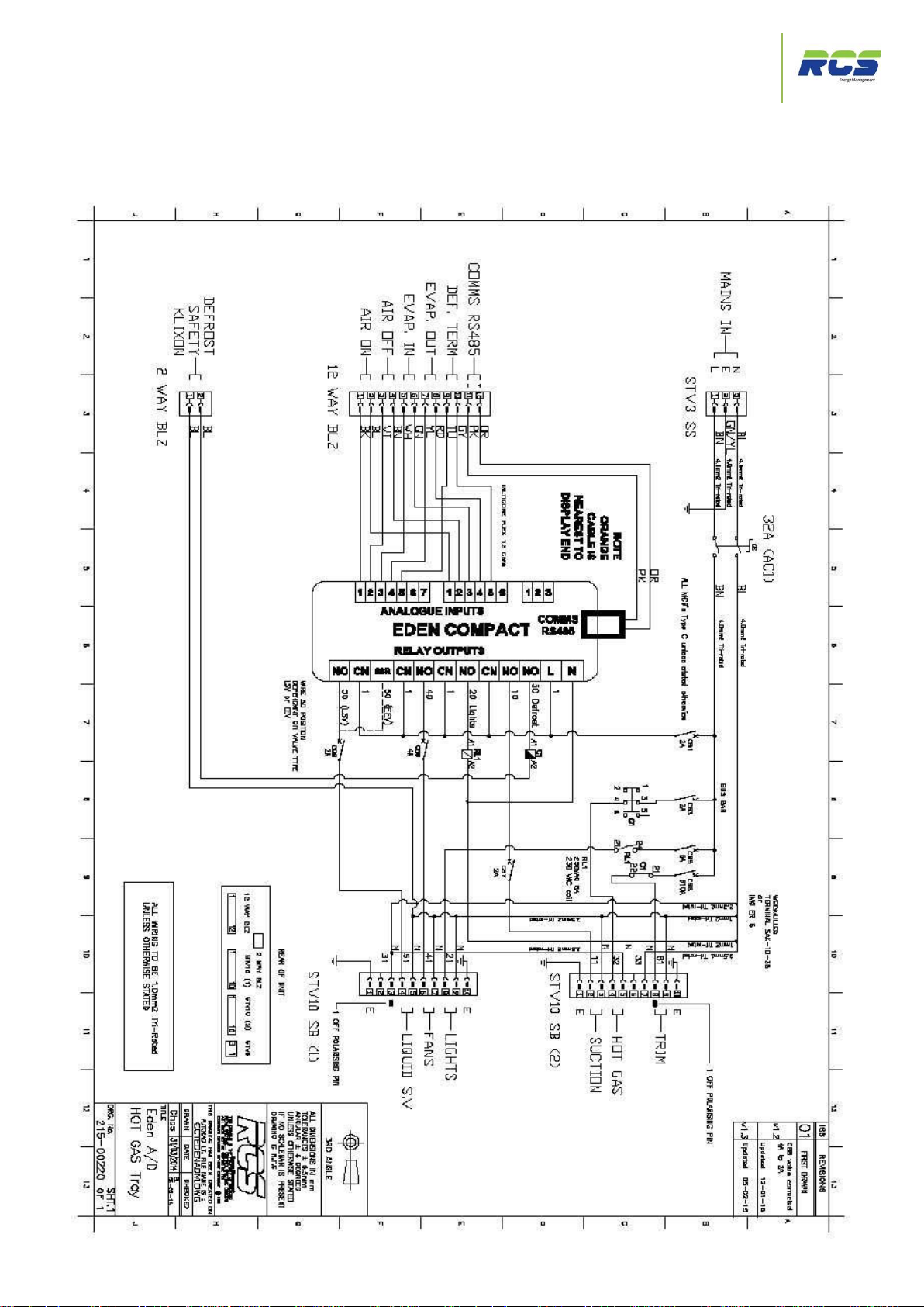
2.6 EP3119, EP3129 (LSV) & EP31110, EP31210 (EEV)
(Hot Gas Defrost & KTUC09 Hot Gas Defrost Legacy replacement) - Circuit
Diagram
Installation Guide | Issue 2.0 | The Eden Power Tray Page 12
Page 13

Connection Details - External Defrost Contactor
The Eden Power Tray
2.7 EP3117, EP3127 (LSV) & EP3118, EP3128 (EEV)
Pin Number
Function
Rating/Designation
1
Earth
2
Not Used
3
Not Used
4
LSV/EEV Live
2A Internal MCB (CB 8)
5
LSV/EEV Neutral
6
Fans Live
4A Internal MCB (CB 9)
7
Fans Neutral
8
Lights Live
6A Internal MCB (CB 5)
9
Lights Neutral
10
Earth
Pin Number
Function
Rating/Designation
1
Earth
2 Suction Live
2A Internal MCB (CB 7)
3
Suction Neutral
4 External Defrost Contactor Live
2A Internal MCB (CB 3)
5
External Defrost Contactor Neutral
6
Not Used
7
Not Used
8
Trim Heater Live
10A Internal MCB (CB 6)
9
Trim Heater Neutral
10
Earth
Pin Number
Function
Rating Designation
1 Unit Supplied with loop fitted
2
(External Defrost Contactor & KTUC09 “Tray” Legacy replacement) Connectivity Details
STV1
STV2
Defrost Safety Klixon
Eden controller power is supplied via an internal 2A MCB (CB 1)
Installation Guide | Issue 2.0 | The Eden Power Tray Page 13
Page 14
External Defrost Contactor Circuit Diagram
The Eden Power Tray
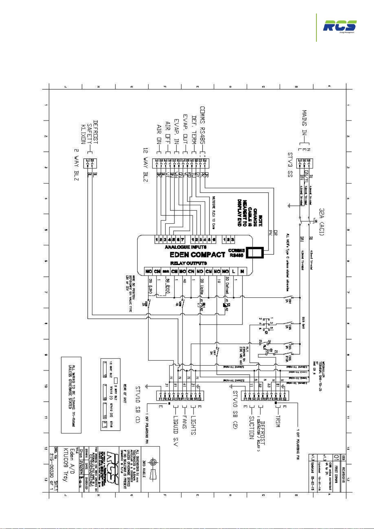
2.8 EP3117, EP3127 (LSV) & EP3118, EP3128 (EEV)
(External Defrost Contactor & KTUC09 “Tray” Legacy replacement) – Circuit
Diagram
Installation Guide | Issue 2.0 | The Eden Power Tray Page 14
Page 15
Connection Details - Minor Assisted Defrost
The Eden Power Tray
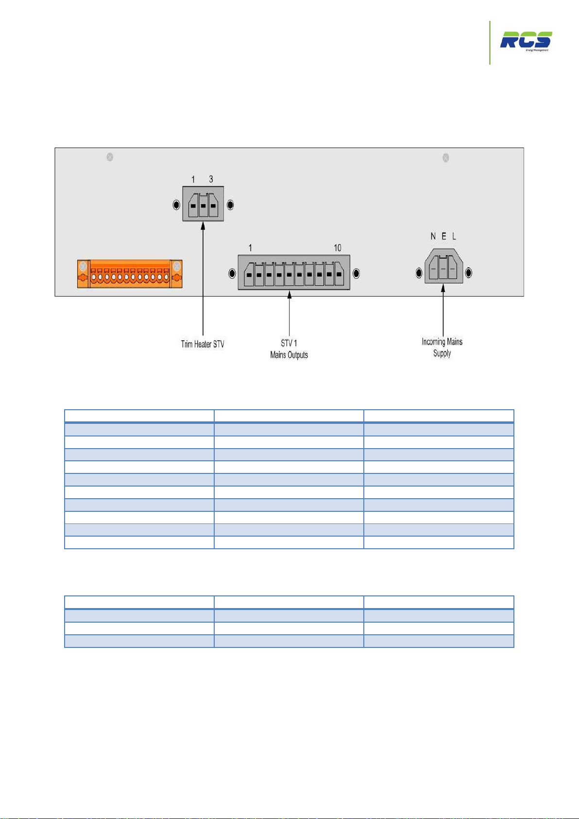
2.9 EP3111 (Minor Assisted Defrost Legacy replacement) –
Pin Number
Function
Rating/Designation
1
Earth
2
Defrost Live
16A Internal MCB (CB4)
3
Defrost Neutral
4 LSV/EEV Live
2A Internal MCB (CB 6)
5
LSV/EEV Neutral
6 Fans Live
2A Internal MCB (CB 5)
7
Fans Neutral
8 Lights Live
6A Internal MCB (CB 3)
9
Lights Neutral
10
Earth
Pin Number
Function
Rating/Designation
1
Trim heater Live
6A Internal MCB (CB 2)
2
Trim Heater Earth
3
Trim Heater Neutral
Connectivity Details
STV1
Trim Heater STV
Eden controller power is supplied via an internal 2A MCB (CB 1)
Installation Guide | Issue 2.0 | The Eden Power Tray Page 15
Page 16
Minor Assisted Defrost Circuit Diagram
The Eden Power Tray
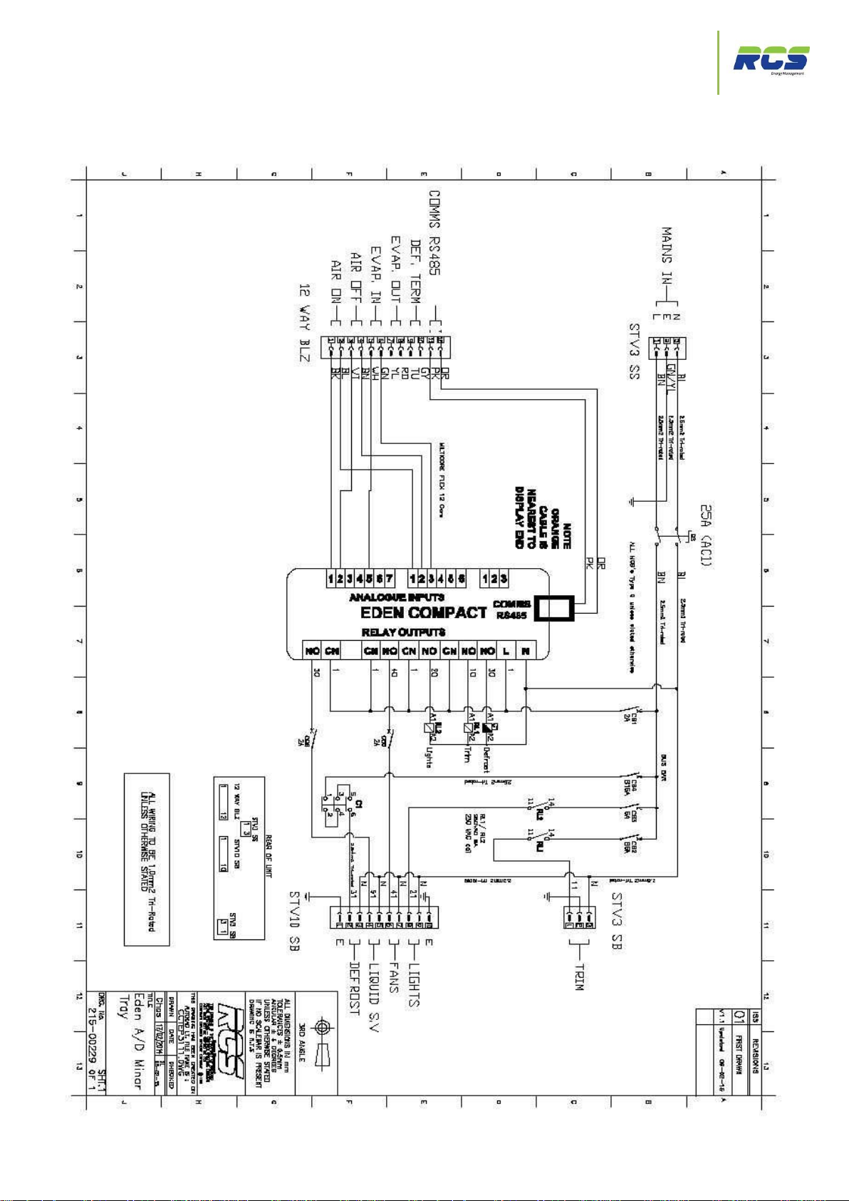
2.10 EP3111 (Minor Assisted Defrost Legacy replacement) – Circuit Diagram
Installation Guide | Issue 2.0 | The Eden Power Tray Page 16
Page 17
Connection Details – Off-Cycle Defrost
The Eden Power Tray
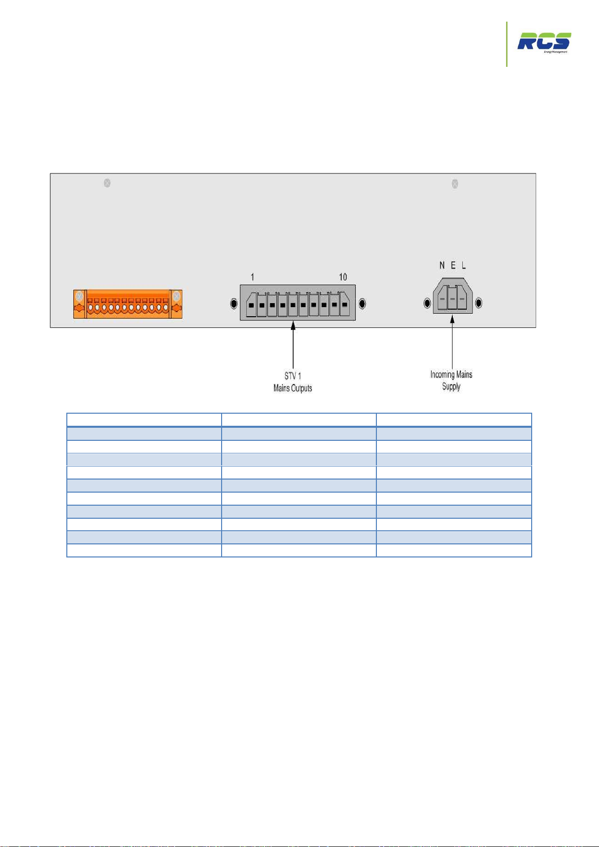
Pin Number
Function
Rating/Designation
1
Earth
2 Curtain Fan Live
4A Internal MCB (CB 3)
3
Curtain Fan Neutral
4 LSV/EEV Live
2A Internal MCB (CB 5)
5
LSV/EEV Neutral
6 Fans Live
4A Internal MCB (CB 4)
7
Fans Neutral
8 Lights Live
6A Internal MCB (CB 2)
9
Lights Neutral
10
Earth
2.11 EP3110, EP3120 (LSV) & EP3112, EP3122 (EEV) (Off-Cycle Defrost)
– Connectivity Details
STV1
Eden controller power is supplied via an internal 2A MCB (CB 1)
Installation Guide | Issue 2.0 | The Eden Power Tray Page 17
Page 18

Off-Cycle Defrost Circuit Diagram
The Eden Power Tray
2.12 EP311, EP3120 (LSV) & EP3112, EP3122 (EEV) (Off-Cycle Defrost)
– Circuit Diagram
Installation Guide | Issue 2.0 | The Eden Power Tray Page 18
Page 19

Connection Details – Sensors & Comms.
The Eden Power Tray
Pin Number
Function
Rating/Designation
1
Air On – Signal
2
Air On – Ground
3
Air Off Sensor – Signal
4
Air Off Sensor – Ground
5
Evaporator In Sensor – Signal
Optional (Set-up option – see section
3.2.1) SU11
6
Evaporator in Sensor – Ground
7
Evaporator Out Sensor – Signal
Optional (Set-up option – see section
3.2.1) SU11
8
Evaporator Out Sensor – Ground
9
Defrost Termination Sensor – Signal
Optional (Set-up option – see section
3.2.4) DF8
10
Defrost Termination Sensor – Ground
11
RS485 Communication Network -
Omitted if IP Variant
12
RS485 Communication Network +
2.13 All Variants – Sensor / communication network connections
12 Way BLZ
Installation Guide | Issue 2.0 | The Eden Power Tray Page 19
Page 20

Chassis – End View
The Eden Power Tray
2.14 All Variants – End View
Installation Guide | Issue 2.0 | The Eden Power Tray Page 20
Page 21

Setting up the controller
The Eden Power Tray
3. Setting up the controller
The Eden Compact can be set up via a variety of different methods:
Through the front panel display and function keys
Through the RCS system manager
Directly via the controllers communication port using a PC
Across an IP network
Subsequent pages will identify and explain each menu group and individual parameter in detail when utilising the function keys
on the front of the Eden controller for set up purposes. Information has been presented in exactly the same format as it will
appear to the user on the display, and descriptions of each function are given along with the maximum, minimum and default
values for HT and LT variants.
If the user wishes to confirm / modify parameters using the RCS system manager then the Eden controllers will need to be
logged onto the system to achieve this, please complete the Setup and Address sections as identified on pages 8-11 before
proceeding to use the system manager.
Controllers can be pre-commissioned with identical non default parameter sets via the use of a PC connected directly into the
Eden controller’s communication port. To achieve this a simple software application is available from RCS upon request.
3.1 Front Panel Display Keys & Icons:-
The Eden Compact consists of a very attractive front panel display and a keypad. The display has 4 digits,
decimal point and icons. It shows temperatures, all parameter values, and the main unit status.
The silicon keypad ensures ease of use and reliability.
The front panel incorporates a blue LED 4 character display for indicating temperatures and status / alarm
messages. The four function keys are identified below:-
Installation Guide | Issue 2.0 | The Eden Power Tray Page 21
Page 22

Setting up the controller
The Eden Power Tray
Alarm
Critical alarm present, see Alarms Menu – Page 10
Service
See Parameter Ti9 – Page 18
HACCP
See Parameter Su9 – Page 9
Valve
Illuminated when Relay 1 is on – Pages 28-29
Fans
Illuminated when Relay 2 is on - Pages 28-29
Lights
Illuminated when Relay 3 is on - Pages 28 - 29
Defrost
Illuminated when Relay 5 is on – Pages 28-29
Network
Off = No Network attached / network failure
On = Network Established
Installation Guide | Issue 2.0 | The Eden Power Tray Page 22
Page 23

Setting up the controller
The Eden Power Tray
3.2 Using the front panel display and function keys
Display Text
Menu Group
Information
Set
Initial controller setup
Setup
Addr
485 / IP comms configuration
Address
rEF
Refrigeration Mode Parameters
Refrigeration
dEF
Defrost Mode Parameters
Defrost
FAnS
Fans parameters
Fans
ti
Time related Parameters
Times
StA
Unit Status Information
Status
ALAr
Unit Alarm Information
Alarms
LtS
Lights related Parameters
Lights
SLP
Sleep Mode
Sleep
SELF
Self Test Mode
Self
To enter setup press the FUNCTION and UP buttons simultaneously for greater than 3 seconds until the
message SEt appears. Pressing the ENTER key again at this point will allow access to the first item in the setup
menu (Su1). Pressing the FUNCTION button at any point will return the user to the previous menu. The UP /
DOWN buttons can be used to scroll through the available menu groups, as listed below. Once the required
menu group is displayed pressing the enter key again will allow access to that group as described above.
The following pages provide details of each menu group in order. It is recommended that the user follows this
sequence to ensure correct setup is achieved.
If no buttons are pressed for a period greater than 3 minutes the display will revert to indicating the actual cabinet
temperature. This applies to all menus.
Installation Guide | Issue 2.0 | The Eden Power Tray Page 23
Page 24

Setting up the controller
The Eden Power Tray
3.2.1 Set Up Menu
I/D
Parameter
Range
Units
Deflt
LSV
Deflt
EEV
Information
Su1
Unit Type
0 = HT Integral
1 = LT Integral
2 = HT Remote
Case
3 = LT Remote
Case
4 = HT Coldstore
5 = LT Coldstore
4 4
Options 1 and 2 not valid if
EEV variant.
Su2
Control Probe Type
0 =Use Air On
Probe
1 = Use Log Probe
Air On
Air On
Selects between using the air
on, or the log probe as the
control temperature. If Su3 is
set to 0 (off) N/A will appear
Su3
Log Probe Type
0 = Off
1 = Logging
2 = Logging with
Alarm
0 - Off
0- Off
Selects the function of the log
probe. (if fitted)
Su4
Trim In Defrost
No
Yes
No
No
Selects the state (on or off) of
the trim heater output during
defrost.
Su5
Trim Output %
0 – 100
%
100
100
Selects the percentage output
level of the trim heater output
on a 100 second time base.
Example – if Su5 = 10% then
trim on for 10 seconds and off
for 90 seconds.
Su6
Relay 4 Function
0 = Suction
1 = Trim
2 = Compressor 2
Suction
Suction
If unit type 1 or 2 is selected
this parameter will default to 2
– compressor 2
Accessed by pressing and holding the FUNCTION and UP keys simultaneously for greater than 3 seconds. The
display will indicate SEt, at this point press the ENTER button again and the display will indicate Su1. This is the
first item in the set up menu. The UP and DOWN keys can be used to scroll through the entire list of set up items
– from Su1 through to Su12. See table below:-
Pressing ENTER whilst displaying any Su number will allow the user to view and modify that particular value by
using the UP / DOWN keys to either increment or decrement the default value. Once the desired value is
displayed press ENTER again to save, or use the FUNCTION key to return to previous menu without saving.
Installation Guide | Issue 2.0 | The Eden Power Tray Page 24
Page 25

Setting up the controller
The Eden Power Tray
I/D
Parameter
Range
Units
Deflt
LSV
Deflt
EEV
Information
Su7
Digital Input 1
Function
0 = Case Clean
1 = Door Open
2 = C1 Fault
3 = Man Trapped
Case Clean
Case -
- Clean
Default for cabinet type 3 and
4 is case clean. If unit type 1
or 2 selected (su1) then
default value becomes 2 – C1
Fault. If unit type 5 or 6
selected (su1) then default
becomes 1 – Door alarm. All
digital inputs are contact sense
N/O. N/C for alarm.
Su8
Digital Input 2
Function
0 = Case Clean
1 = Door Open
2 = C2 Fault
3 = Man Trapped
Case -
- Clean
Case -
- Clean
Default for cabinet type 3 and
4 is case clean. If unit type 1
or 2 selected (su1) then
default value becomes 2 – C2
Fault. If unit type 5 or 6
selected (su1) then default
becomes 1 – Man Trapped
alarm. All digital inputs are
contact sense N/O. - N/C for
alarm.
Su9
HACCP Function
0 = Off
1 = On
2 = Flashing
0 - Off
0- Off
Selects the state of the front
panel HACCP icon.
Su10
Sensor Type
0 = PT1000
1 = 5K NTC
2 = 10K NTC
3 = 2K2 NTC
PT1000
PT1000
Selects the temperature
sensor type being used. Note
– sensor types cannot be
mixed on a single controller
Su11
Evaporator Probes
Fitted
0 = Not Fitted
1 = Fitted
1 - Fitted
1 - Fitted
Allows the user to select if
Evaporator In and Out sensors
are fitted.
Su12
Number of
Compressors
1 2 2 2
Selects the number of
compressors in use when unit
type 1 or 2 (integral) is
configured
Installation Guide | Issue 2.0 | The Eden Power Tray Page 25
Page 26

Setting up the controller
The Eden Power Tray
3.2.2 Controller address and communications menu.
I/D
Parameter
Range
Units
Deflt
LSV
Deflt
EEV
Information
485A
Controller RS485
communication
address
(unit number)
0.0 – 499.9
0.0
0.0
Allows the user to set the
controllers network address for
RS485 legacy systems
485C
Controller RS485
communication baud
rate
0 = 9600
1 = 600
9600
9600
Allows the user to set the
controllers network baud rate for
RS485 legacy systems
IP-1
IP Address Byte 1
0 – 255
0 0
Allows the user to set the first
byte of the controllers IP
address. Note- If DHCP is set to
yes this value is not editable.
IP-2
IP Address Byte 2
0 – 255
0 0
Allows the user to set the
second byte of the controllers IP
address. Note- If DHCP is set to
yes this value is not editable.
IP-3
IP Address Byte 3
0 – 255
0 0
Allows the user to set the third
byte of the controllers IP
address. Note- If DHCP is set to
yes this value is not editable.
IP-4
IP Address Byte 4
0 – 255
0 0
Allows the user to set the fourth
byte of the controllers IP
address. Note- If DHCP is set to
yes this value is not editable.
Sn -1
Sub-Net Address Byte
1
0 – 255
0 0
Allows the user to set the First
byte of the controllers sub net
mask. Note- If DHCP is set to
yes this value is not editable.
Accessed by pressing and holding the FUNCTION and UP keys simultaneously for greater than 3 seconds. The
display will indicate SEt, Press the DOWN key once - the display will indicate Addr at this point press the ENTER
button and the display will indicate 485A. This is the first item in the address menu. The UP and DOWN keys can
be used to scroll through the entire list of set up items – from 485A through to DGT. See table below:Pressing ENTER whilst displaying any item will allow the user to view and modify that particular value by using
the UP / DOWN keys to either increment or decrement the default value. Once the desired value is displayed
press ENTER again to save, or use the FUNCTION key to return to previous menu without saving.
Installation Guide | Issue 2.0 | The Eden Power Tray Page 26
Page 27

Setting up the controller
The Eden Power Tray
I/D
Parameter
Range
Units
Deflt
LSV
Deflt
EEV
Information
Sn -2
Sub-Net Address Byte
2
0 – 255
0 0
Allows the user to set the
second byte of the controllers
sub net mask. Note- If DHCP is
set to yes this value is not
editable.
Sn -3
Sub-Net Address Byte
3
0 – 255
0 0
Allows the user to set the third
byte of the controllers sub net
mask. Note- If DHCP is set to
yes this value is not editable.
Sn -4
Sub-Net Address Byte
4
0 – 255
0 0
Allows the user to set the fourth
byte of the controllers sub net
mask. Note- If DHCP is set to
yes this value is not editable.
Gt1
Network Gateway
Address Byte 1
0 – 255
0 0
Allows the user to set the first
byte of the network gateway
address.
Gt2
Network Gateway
Address Byte 2
0 – 255
0 0
Allows the user to set the
second byte of the network
gateway address.
Gt3
Network Gateway
Address Byte 2
0 – 255
0 0
Allows the user to set the third
byte of the network gateway
address.
Gt4
Network Gateway
Address Byte 2
0 – 255
0 0
Allows the user to set the fourth
byte of the network gateway
address.
NtP1
NTP server Address
Byte 1
0 – 255
0 0
Allows the user to set the first
byte of the NTP server address
NtP2
NTP server Address
Byte 2
0 – 255
0 0
Allows the user to set the
second byte of the NTP server
address
NtP3
NTP server Address
Byte 3
0 – 255
0 0
Allows the user to set the third
byte of the NTP server address
NtP4
NTP server Address
Byte 4
0 – 255
0 0
Allows the user to set the fourth
byte of the NTP server address
dHCP
DHCP Enabled
Yes
No
Yes
Yes
Configures if DHCP is being
used
dntP
NTP server address
obtained via DHCP
Yes
No
Yes
Yes
Configures if the NTP server
address is automatically
obtained via DHCP
dGt
Network gateway
address obtained via
DHCP
Yes
No
Yes
Yes
Configures if the gateway
address is automatically
obtained via DHCP
If the user is unsure of any network related parameter please consult your network administrator
Installation Guide | Issue 2.0 | The Eden Power Tray Page 27
Page 28

Setting up the controller
The Eden Power Tray
3.2.3 Controllers Refrigeration related parameter menu.
I/D
Parameter
Range
Units
Deflt
LSV
Deflt
EEV
Information
rF1 Force Refrigeration
No
Yes
No
No
Allows the user to force the
controller into a forced
refrigeration
state. During the force
refrigeration
state any scheduled defrosts will
be
ignored. The controller will
remain in
this state until either NO is
selected or a period of 60
minutes has elapsed.
rF2
Temperature
Setpoint
-40.0°C - +35.0°C
°C
1.0°C HT
-20°C LT
-1.0°C HT C/S
-20°C -
LT C/S
1.0°C HT
-20°C LT
-1.0°C HT C/S
-20°C LT C/S
Temperature at which inlet valve
or compressor/s will switch on
rF3
Temperature Diff.
0.2 – 5.0°C
°C
1.0°C HT
2.0°C LT
1.0°C HT
2.0°C LT
Differential temperature below
the temperature setpoint at which
the inlet valve or compressor will
switch off
rF4 Control Ratio
0 – 100%
%
66%
Cabinet
100%
Coldstore
66%
Cabinet
100%
Coldstore
Ratio of Air On temperature that
is used to calculate the estimated
cabinet temperature for control.
The remaining percentage used
is Air off temperature.
rF5 Display Ratio
0 – 100%
%
66
66
As above only applied to the front
panel display temperature.
Accessed by pressing and holding the FUNCTION and UP keys simultaneously for greater than 3 seconds. The
display will indicate SEt, Press the DOWN key 2 times - the display will indicate rEF, at this point press the
ENTER button and the display will indicate rF1. This is the first item in the REFRIGERATION menu. The UP and
DOWN keys can be used to scroll through the entire list of the rEF menu – from rF1 through to Rf16. See table
below:Pressing ENTER whilst displaying any item will allow the user to view and modify that particular value by using
the UP / DOWN keys to either increment or decrement the default value. Once the desired value is displayed
press ENTER again to save, or use the FUNTION key to return to the previous menu without saving.
Installation Guide | Issue 2.0 | The Eden Power Tray Page 28
Page 29

Setting up the controller
The Eden Power Tray
I/D
Parameter
Range
Units
Deflt
LSV
Deflt
EEV
Information
rF6 Superheat Setpoint
0.0 - 9.0
°C
6.0°C
6.0°C
The controller will attempt to
maintain this superheat setpoint
N/A will be displayed if LSV
version.
rF7 EEV Injection
percentage
0 – 100%
%
45%
45%
Sets the value of the EEV when
in a recovery state. N/A will be
displayed if LSV version.
rF8 Air On Alarm
Setpoint
-40.0°C - +35.0°C
°C
8.0 HT
-10.0 LT
8.0 HT
-10.0 LT
Sets the Air On alarm setpoint
rF9 Air Off Alarm
Setpoint
-40.0°C - +35.0°C
°C
4.0 HT
-20.0 LT
3.0 HT
C/S
-18.0 LT
C/S
4.0 HT
-20.0 LT
3.0 HT
C/S
-18.0 LT
C/S
Sets the Air Off alarm setpoint
rF10
Logging Probe OT
Alarm
Setpoint
-40.0°C - +35.0°C
°C
10.0 HT
-12.0 LT
10.0 HT
-12.0 LT
Sets the log probe over
temperature alarm setpoint.
NOTE – N/A will be displayed if
Su3 is not set to 2
rF11
Logging Probe UT
Alarm
Setpoint
-40.0°C - +35.0°C
°C
-5.0 HT
-35.0 LT
-5.0 HT
-35.0 LT
Sets the log probe under
temperature alarm setpoint
NOTE – N/A will be displayed if
Su3 is not set to 2
rF12
EEV Minimum
Opening
0 – 100%
%
15%
15%
Sets the minimum valve opening
during normal operation. The
controller will prevent the valve
from closing below this value.
N/A will be displayed if LSV
version.
rF13
Manual EEV Control
0 = No
1 = Yes
0 - No
0 – No
Allows the user to manually
control the EEV valve opening %
if set to Yes. Used in conjunction
with rF14 N/A will be displayed if
LSV version.
rF14
Manual EEV
Opening
0 – 100 %
% 0 0
If rF13 is set to yes, the manual
% opening value. The EEV will
remain at this percentage until
manual control is exited N/A will
be displayed if LSV version.
rF15
Air On setpoint
-40.0°C - +20.0°C
°C
-3.0 HT
-20.0 LT
-3.0 HT
-20.0 LT
Temperature at which inlet valve
or compressor/s will switch on.
Note N/A will be displayed if not
type 4 or 5 (coldstore)
rF16
Evaporator Offset to
allow injection state
-10.0°C - +10.0°C
°C
0.0 HT
2.0 LT
0.0 HT
2.0 LT
Temperature offset from the ECT
setpoint at which the injection
(recovery) state can be entered
Note N/A will be displayed if not
type 4 or 5 (coldstore)
Installation Guide | Issue 2.0 | The Eden Power Tray Page 29
Page 30

Setting up the controller
The Eden Power Tray
3.2.4 Controllers DEFROST menu.
I/D
Parameter
Range
Units
Deflt
LSV
Deflt
EEV
Information
dF1
First Defrost Time
00:01 – 23:59
hh:mm
01:00
01:00
Sets the first scheduled defrost
time
dF2
Number of Defrosts
per
Day
0 – 8 6 6 Sets the number of defrost
cycles per day. Automatically
spaced equally from the first
defrost time (dF1)
dF3
Maximum Defrost
Duration
00:00 – 01:59
hh:mm
00:30
00:30
Maximum time that a scheduled
defrost cycle can run. Note Timed from the end of defrost
Minimum (dF4)
dF4
Minimum Defrost
Duration
00:00 – 01:59
hh:mm
00:05
00:05
Minimum time that a scheduled
defrost cycle must run before
terminating. If termination
temperature is achieved during
this period the controller will turn
off the defrost output but not
return to refrigeration mode until
period has elapsed.
dF5
Pump Down
Duration
0 – 60
mm 0 0
Pump down time prior to
minimum defrost duration (dF4)
commencing
dF6
Drain Down Duration
0 – 60
mm
02
02
Drain down time after defrost has
terminated to allow water to be
cleared.
Accessed by pressing and holding the FUNCTION and UP keys simultaneously for greater than 3 seconds. The
display will indicate SEt, Press the DOWN key 3 times - the display will indicate dEF, at this point press the
ENTER button and the display will indicate dF1. This is the first item in the DEFROST menu. The UP and DOWN
keys can be used to scroll through the entire list of the DEFROST menu – from dF1 through to dF13. See table
below:Pressing ENTER whilst displaying any item will allow the user to view and modify that particular value by using
the UP / DOWN keys to either increment or decrement the default value. Once the desired value is displayed
press ENTER again to save, or use the FUNCTION key to return to the previous menu without saving.
Installation Guide | Issue 2.0 | The Eden Power Tray Page 30
Page 31

Setting up the controller
The Eden Power Tray
I/D
Parameter
Range
Units
Deflt
LSV
Deflt
EEV
Information
dF7
Defrost termination
Temperature
-40.0°C - +35.0°C
°C
8.0°C
8.0°C
Scheduled defrost will terminate
when the defrost termination
sensor reaches this temperature.
Note – If the defrost termination
sensor is not fitted (or faulty)
then defrost termination will
occur when the Evap. In sensor
reaches this temperature if fans
off, or the Air Off sensor reaches
this temperature if fans on.
dF8
Defrost termination
sensor in Use
0 = Defrost
1 = Air Off
2 Evap. In
0 =
Defrost
0 =
Defrost
Allows the user to select the
sensor used for defrost
termination.
dF9
Defrost Type
0 = Electric
1 = Hot Gas
0 Electric
0 –
Electric
Allows the user to select if
electric or hot gas defrost in
being used.
dF10
Suction Valve after
Hot
Gas defrost
Open
Closed
Closed
Closed
Allows the user to select if the
suction valve is open or closed
during the drain down period.
Only applicable if Hot Gas
defrost is selected at dF9
dF11
Force Defrost
Yes
No
No
No
Sets the controller into defrost.
The
controller will remain in this mode
until either No is selected or max
defrost duration (Df3) time
is exceeded.
dF12
Trigger Defrost
Yes
No
No
No
Allows the user to trigger a
defrost cycle additional to those
scheduled. All normal termination
criteria apply.
dF13
LSV during Hot Gas
Defrost
0 = Closed
1 = Open
0 Closed
0 –
Closed
Allows the user to select if the
evaporator inlet valve is open or
closed during a hot gas defrost.
Only applicable if Hot Gas
defrost is selected at dF9
dF14
Suppress Full Length
Defrost
Yes
No
No
No
Allows the user to prevent the
controller from entering a full
length defrost at the scheduled
time/s when the defrost
termination temperature is
above the termination setpoint
(df7) at the start of defrost.
Installation Guide | Issue 2.0 | The Eden Power Tray Page 31
Page 32

Setting up the controller
The Eden Power Tray
3.2.5 Controllers Fan related parameter menu.
I/D
Parameter
Range
Units
Deflt
LSV
Deflt
EEV
Information
Fn1 Fans Only Mode
0 = No
1 = Yes
2 = Lights and
Fans
Only
0 – No
0 – No
Allows the user to set the
controller
into Fans Only Mode. The
controller
will remain in this mode until No
is
selected.
Fn2
Maximum Fans off
Time
0 – 60
mm 0 0
Maximum time for which the fans
are switched off following
draindown.
Fn3
Fans Off
Temperature
During Defrost
-40.0°C - +35.0°C
°C 8.0°C
(HT)
-10.0°C
(LT)
8.0°C
(HT)
-10.0°C
(LT)
Allows the user to determine the
temperature at which fans will
turn off during defrost. Once
turned off by this setting fans will
remain off for the remaining
defrost duration.
NOTE If -40.0°C is selected fans
will be always off during defrost
Fn4 Fans Off Delay Time
0 – 60
ss 0 0
The delay time before fans are
switched off when a door open
state is entered. Note N/A will be
displayed if not type 4 or 5
(coldstore)
Fn5
Fans Holdoff End
setpoint
-40.0°C - +35.0°C
°C 0.0°C
(HT)
-10.0°C
(LT)
0.0°C
(HT)
-10.0°C
(LT)
Defrost termination sensor
temperature which when
achieved will allow fans to be
switched on.
Fn6
Fans Pulse In defrost
No
Yes
0 = No
0 = No
Allows the user to select if
evaporator fans pulse during
defrost
Accessed by pressing and holding the FUNCTION and UP keys simultaneously for greater than 3 seconds. The
display will indicate SEt, Press the DOWN key 4 times - the display will indicate FAns, at this point press the
ENTER button and the display will indicate Fn1. This is the first item in the FANS menu. The UP and DOWN keys
can be used to scroll through the entire list of the FANS menu – from Fn1 through to Fn9. See table below:Pressing ENTER whilst displaying any item will allow the user to view and modify that particular value by using
the UP / DOWN keys to either increment or decrement the default value. Once the desired value is displayed
press ENTER again to save, or use the FUNCTION key to return to the previous menu without saving.
Installation Guide | Issue 2.0 | The Eden Power Tray Page 32
Page 33

Setting up the controller
The Eden Power Tray
I/D
Parameter
Range
Units
Deflt
LSV
Deflt
EEV
Information
Fn7
Fans On setpoint
-10.0°C - +30.0°C
°C 50.0°C
(HT)
-1.0°C
(LT)
5.0°C
(HT)
-1.0°C
(LT)
Cold store Only.
Defrost termination sensor
temperature or Air On
temperature which when
achieved will allow fans to be
switched on. Note N/A will be
displayed if not type 4 or 5
(coldstore)
Fn8
Fans Pulse Time
5 – 600
ss
60
60
Time in seconds for which the
fans will alternate between on
and off if Fn6 is set to yes
Fn9
Door Open State
Closes
Valve
0 = No
1 = Yes
0 – No
0 – No
Allows the user to select if a door
open state closes the evaporator
inlet valve. Note N/A will be
displayed if not type 4 or 5
(coldstore)
Installation Guide | Issue 2.0 | The Eden Power Tray Page 33
Page 34

Setting up the controller
The Eden Power Tray
3.2.6 Controllers time related parameter menu.
I/D
Parameter
Range
Units
Deflt
LSV
Deflt
EEV
Information
ti1
Time of Day
00:00 –
23:59
hh:mm
00:00
00:00
Allows the user to set the correct
time of day into the controller. Note
on networked systems the time of
day will automatically be down
loaded from the host system
ti2
Current Date
01:01 –
31:12
dd:mm
00:00
00:00
Sets the controllers current date
ti3
Current Year
2012 -2100
0000
0000
Sets the controllers current year
ti4
Time of Next
Defrost
hh:mm
Allows the user to view the time of
the next scheduled defrost cycle.
ti5
Time Since last
defrost
hh:mm
Allows the user to view the time
since the last scheduled defrost
cycle occurred.
ti6
Duration of last
defrost
hh:mm
Allows the user to view the duration
time of the last scheduled defrost
cycle.
ti7
Duration of current
defrost
hh:mm
Allows the user to view the elapsed
time of a current defrost cycle.
ti8
Door Alarm Delay
0 – 120
mm
Delay after the door open input is
asserted before the alarm occurs.
Note N/A will be displayed if not
type 4 or 5 (coldstore)
ti9
Service Interval
Time
0 – 130
khrs
60
60
Running time in KHrs (1000x)
before the front panel service
(spanner) icon is illuminated. Reset
can be achieved by changing the
value to 0 then back to the desired
interval.
ti10
Air On Alarm Delay
0 – 120
mm
20
20
Delay for the Air On OT alarm
Accessed by pressing and holding the FUNCTION and UP keys simultaneously for greater than 3 seconds. The
display will indicate SEt, Press the DOWN key 5 times - the display will indicate Ti, at this point press the ENTER
button and the display will indicate Ti1. This is the first item in the TIMES menu. The UP and DOWN keys can be
used to scroll through the entire list of the TIME menu – from TI1 through to Ti19. See table below:Pressing ENTER whilst displaying any item will allow the user to view and modify that particular value by using
the UP / DOWN keys to either increment or decrement the default value. Once the desired value is displayed
press ENTER again to save, or use the FUNCTION key to return to previous menu without saving.
Installation Guide | Issue 2.0 | The Eden Power Tray Page 34
Page 35

Setting up the controller
The Eden Power Tray
I/D
Parameter
Range
Units
Deflt
LSV
Deflt
EEV
Information
ti11
Air Off Alarm Delay
0 – 120
mm
20
20
Delay for the Air Off OT alarm
ti12
Log Probe Alarm
Delay
00:00 –
02:00
hh:mm
00:20
00:20
Delay for the log probe alarm
NOTE – N/A will be displayed if
Su3 is not set to 2
ti13
Cycle Time
0 – 120
mm
60
60
Energy saving feature (LSV use)
see appendix 1.
ti14
EEV Injection Time
0 – 30
mm 4 4
Maximum period the controller can
be in an injection (stall prevention)
state. N/A will be displayed if LSV
version.
ti15
Pull Down Time
0 – 30
ss 8 8
Time after draindown, before an
injection state (recovery) state can
be entered
ti16
Door Open Time
0 – 60
mm
Displays the time a cold store door
has been continuously open for.
Note N/A will be displayed if not
type 4 or 5 (coldstore)
ti17
Door Interlock
Time
0 – 60
mm
0
(HT)
5
(LT)
0
(HT)
5
(LT)
Maximum time for which fans and
/or inlet valve are off / closed when
a cold store door is open. Note N/A
will be displayed if not type 4 or 5
(coldstore)
ti18
Compressor/s start
holdoff Time
0 – 15
mm 4 4
Time period following initial power
up of the controller before
compressors can be started –
Integral use only
ti19
Compressor/s
Restart
Time
0 – 15
mm 4 4
Anti – short cycle time for
compressor 1 and 2 – Integral use
only
Ti20
Compressor/s
stage Time
0 – 15
mm 4 4
Period which must elapse between
compressor A changing state and
subsequent change of state of
compressor B – Integral use only
Ti21
Compressor/s
Minimum On Time
0 – 15
mm 4 4
Minimum time compressor/s must
run once started – Integral use
only
Ti22
Compressor/s
Minimum Off Time
0 – 15
mm 4 4
Minimum time compressor/s must
be stopped once switched off –
Integral use only
Installation Guide | Issue 2.0 | The Eden Power Tray Page 35
Page 36

Setting up the controller
The Eden Power Tray
3.2.7 Controllers current status menu.
I/D
Parameter
Range
Units
Deflt
LSV
Deflt
EEV
Information
St1
Air On Temperature
°C Displays the current Air On sensor
Temperature.
St2
Air Off Temperature
°C
Displays the current Air Off sensor
Temperature
St3
Evaporator In
Temperature
°C
Displays the current Evap. In sensor
Temperature
St4
Evaporator Out
Temperature
°C
Displays the current Evap. Out sensor
Temperature
St5
Superheat
°C
Displays the current superheat
Temperature
St6
Defrost sensor
Temperature
°C
Displays the current Defrost termination
sensor Temperature
St7
Estimated cabinet
Temperature
°C
Displays the current estimated cabinet
temperature. This is defined by the ratio
of air on temperature set within the rEF
menu at rF5 (Display Ratio)
St8
Log Probe
Temperature
°C
Displays the current log sensor
Temperature.
St9
Analogue channel 7
Displays the current value of analogue
input
channel 7. (Hardware configurable).
St10
Trim Output
percentage
% Displays the current percentage of the
controllers trim output.
St11
Digital Input 1
Open
Closed
Displays the current state of controllers
digital input 1. Function dependant upon
selection made in SETUP menu – Su7
Accessed by pressing and holding the FUNCTION and UP keys simultaneously for greater than 3 seconds. The
display will indicate SEt, Press the UP key 6 times - the display will indicate StA, at this point press the ENTER
button and the display will indicate St1. This is the first item in the STATUS menu. The UP and DOWN keys can
be used to scroll through the entire list of the STATUS menu – from St1 through to St20. See table below: Pressing ENTER whilst displaying any item will allow the user to view that particular value. None of the items
within this menu are user editable. Use the FUNCTION key to return to previous menu.
Installation Guide | Issue 2.0 | The Eden Power Tray Page 36
Page 37

Setting up the controller
The Eden Power Tray
I/D
Parameter
Range
Units
Deflt
LSV
Deflt
EEV
Information
St12
Digital Input 2
Open
Closed
Displays the current state of controllers
digital input 2. Function dependant upon
selection made in SETUP menu – Su8
St13
Case Clean
On
Off
Displays if the controller is currently in
case clean mode. (all outputs off)
St14
EEV percentage
open
% Displays the current percentage opening
of the EEV. .N/A will be displayed if LSV
version.
St15
Compressor 1 Fault
Yes
No
Displays the current fault status of C1
(Integral only)
St16
Compressor 2 Fault
Yes
No
Displays the current fault status of C2
(Integral only)
St17
Compressor 1
Running
Yes
No
Displays the current status of controllers
C1 output. (Integral only)
St18
Compressor 2
Running
Yes
No
Displays the current status of controllers
C2 output. (Integral only)
St19
Software Version
Displays controllers software version
St20
Display software
version
Displays controllers display version
Installation Guide | Issue 2.0 | The Eden Power Tray Page 37
Page 38

Setting up the controller
The Eden Power Tray
3.2.8 Controllers current alarms menu.
I/D
Parameter
Range
Units
Deflt
LSV
Deflt
EEV
Information
AL1
Any Alarms
Yes
No
Allows the user to quickly
establish
if any alarm conditions are
currently
Active.
AL2
Air On OT
Yes
No
Indicates if the controller
currently has an Air On over
temperature alarm.
AL3
Air Off OT
Yes
No
Indicates if the controller
currently has an Air Off over
temperature alarm.
AL4
Air On Sensor
Failure
Yes
No
Indicates if the controller
currently has a faulty Air On
temperature sensor.
AL5
Air On Sensor
Failure
Yes
No
Indicates if the controller
currently has a faulty Air Off
temperature sensor.
AL6
Evaporator In
Sensor
Failure
Yes
No
Indicates if the controller
currently has a faulty Evap. In
temperature sensor.
AL7
Evaporator Out
Sensor
Failure
Yes
No
Indicates if the controller
currently has a faulty Evap.
Out temperature sensor.
AL8
Defrost Termination
Sensor Failure
Yes
No
Indicates if the controller
currently has a faulty Defrost
Termination temperature
sensor.
Accessed by pressing and holding the FUNCTION and UP keys simultaneously for greater than 3 seconds. The
display will indicate SEt, Press the UP key 4 times - the display will indicate ALAr, at this point press the ENTER
button and the display will indicate AL1. This is the first item in the ALARMS menu. The UP and DOWN keys can
be used to scroll through the entire list of the ALARMS menu – from AL1 through to AL14. See table below:Pressing ENTER whilst displaying any item will allow the user to view that particular value. None of the items
within this menu are user editable. Use the FUNCTION key to return to previous menu.
Installation Guide | Issue 2.0 | The Eden Power Tray Page 38
Page 39

Setting up the controller
The Eden Power Tray
I/D
Parameter
Range
Units
Deflt
LSV
Deflt
EEV
Information
AL9
Logging Sensor
Failure
Yes
No
Indicates if the controller
currently has a faulty Log
temperature sensor.
AL10
Door Open
(Cold store Only)
Yes
No
Indicates if the controller
currently has a Door Open
alarm Note N/A will be
displayed if not type 4 or 5
(coldstore)
AL11
Man Trapped
(Cold store Only)
Yes
No
Indicates if the controller
currently has a Man Trapped
alarm Note N/A will be displayed
if not type 4 or 5 (coldstore)
AL12
Insufficient Data
Yes
No
Indicates if the controller
currently has an Insufficient
Data alarm. Note – Usually
occurs when defrost time 1
has not been set.
AL13
Compressor 1
Alarm
(Integral Only)
Yes
No
Indicates if the controller
currently has a Compressor 1
Fault.
AL14
Compressor 2
Alarm
(Integral Only)
Yes
No
Indicates if the controller
currently has a Compressor 2
Fault.
AL15
Critical Probe Fault
Yes
No
Set if the controller currently
has more than one
temperature sensor in a fault
condition.
Note – All of the above alarms if present will cause the front panel Bell Icon to be illuminated.
Installation Guide | Issue 2.0 | The Eden Power Tray Page 39
Page 40

Setting up the controller
The Eden Power Tray
3.2.9 Controllers lights related parameter menu.
I/D
Parameter
Range
Units
Deflt
LSV
Deflt
EEV
Information
Li1
Lights control Mode
0 – Remote
1 – Local
2 – Off
3 – On
2 2
Allows the user to set the control
of
case lights:0 = Case lights controlled via
host
System manager.
1 = Case lights controlled via
controller schedule (see Li2 –
Li15)
2 = Always Off
3 = Always On
Li2
Sunday Lights On Time
00:00 – 23:59
hh:mm
08:00
08:00
Available if Li1 set to 1 - Local
Li3
Sunday Lights Off Time
00:00 – 23:59
hh:mm
22:00
22:00
Available if Li1 set to 1 - Local
Li4
Monday Lights On Time
00:00 – 23:59
hh:mm
08:00
08:00
Available if Li1 set to 1 - Local
Li5
Monday Lights Off Time
00:00 – 23:59
hh:mm
22:00
22:00
Available if Li1 set to 1 - Local
Li6
Tuesday Lights On Time
00:00 – 23:59
hh:mm
08:00
08:00
Available if Li1 set to 1 - Local
Li7
Tuesday Lights Off Time
00:00 – 23:59
hh:mm
22:00
22:00
Available if Li1 set to 1 - Local
Li8
Wednesday Lights On
Time
00:00 – 23:59
hh:mm
08:00
08:00
Available if Li1 set to 1 - Local
Li9
Wednesday Lights Off
Time
00:00 – 23:59
hh:mm
22:00
22:00
Available if Li1 set to 1 - Local
Li10
Thursday Lights On Time
00:00 – 23:59
hh:mm
08:00
08:00
Available if Li1 set to 1 - Local
Li11
Thursday Lights Off Time
00:00 – 23:59
hh:mm
22:00
22:00
Available if Li1 set to 1 - Local
Li12
Friday Lights On Time
00:00 – 23:59
hh:mm
08:00
08:00
Available if Li1 set to 1 - Local
Li13
Friday Lights Off Time
00:00 – 23:59
hh:mm
22:00
22:00
Available if Li1 set to 1 - Local
Li14
Saturday Lights On Time
00:00 – 23:59
hh:mm
08:00
08:00
Available if Li1 set to 1 - Local
Li15
Saturday Lights Off Time
00:00 – 23:59
hh:mm
22:00
22:00
Available if Li1 set to 1 - Local
Accessed by pressing and holding the FUNCTION and UP keys simultaneously for greater than 3 seconds. The
display will indicate SEt, Press the UP key 3 times - the display will indicate LtS, at this point press the ENTER
button and the display will indicate Li1. This is the first item in the LIGHTS menu. The UP and DOWN keys can
be used to scroll through the entire list of the LIGHTS menu – from Li1 through to Li15. See table below:Pressing ENTER whilst displaying any item will allow the user to view and modify that particular value by using
the UP / DOWN keys to either increment or decrement the default value. Once the desired value is displayed
press ENTER again to save, or use the FUNCTION key to return to previous menu without saving.
Installation Guide | Issue 2.0 | The Eden Power Tray Page 40
Page 41

Setting up the controller
The Eden Power Tray
3.2.10 Controller sleep mode menu.
I/D
Parameter
Range
Units
Deflt
LSV
Deflt
EEV
Information
SP1
Sleep Mode
Yes
No
No
No
Allows the user to set the
controller
Into sleep mode (All outputs off).
The controller will continue to
report temperature values to the
host
Supervisory system during sleep
mode periods.
The controller will remain in sleep
mode if selected until the user
selects No.
Accessed by pressing and holding the FUNCTION and UP keys simultaneously for greater than 3 seconds. The
display will indicate SLP, Press the UP key 2 times - the display will indicate SLP, at this point press the ENTER
button and the display will indicate SP1. This is the only item in the SLEEP menu. See table below:-
Pressing ENTER whilst displaying SP1 will allow the user to view and modify that particular value by using the
UP / DOWN keys to either increment or decrement the default value. Once the desired value is displayed press
ENTER again to save, or use the FUNCTION key to return to previous menu without saving.
Note: - Caution should be used when setting this value as the controller will remain in sleep mode indefinitely
once selected.
Installation Guide | Issue 2.0 | The Eden Power Tray Page 41
Page 42

Setting up the controller
The Eden Power Tray
3.2.11 Controller self test menu.
I/D
Parameter
Range
Units
Deflt
LSV
Deflt
EEV
Information
SF1
Self Test
No
Yes
No
No
Allows the user to set the
controller into self test mode.
The controller will cycle all outputs
consecutively for a period of 2
minutes.
The order in which the outputs are
switched are:-
Liquid valve
Fans
Defrost
Suction / Trim
Lights
Accessed by pressing and holding the FUNCTION and UP keys simultaneously for greater than 3 seconds. The
display will indicate SEt, Press the UP key once - the display will indicate SELF, at this point press the ENTER
button and the display will indicate SF1. This is the only item in the SELF TEST menu.
See table below:Pressing ENTER whilst displaying SF1 will allow the user to view and modify the default value of NO to YES. If
YES is selected the controller will remain in self test for a period of two minutes, or until NO is selected, if sooner.
The FUNCTION key can be used to return to the previous menu.
Installation Guide | Issue 2.0 | The Eden Power Tray Page 42
Page 43

Cleaning
The Eden Power Tray
4. Cleaning
Only use a soft lint-free cloth. Abrasive cloths, towels, paper towels and similar items may damage the Eden
controller. Keep any liquids away from the controller; don’t use aerosol sprays, solvents or abrasives.
Installation Guide | Issue 2.0 | The Eden Power Tray Page 43
Page 44

Specification
The Eden Power Tray
5. Specification
5.1 Power requirements:
Supply Voltage Range: 220 – 240 Vac ±10%
Supply Frequency: 50 – 60 Hz
Maximum supply current: 32 Amps
Typical supply current: Loading Dependant
Operating temperature range: +5C to +50C
Operating Humidity: 80% maximum
Storage temperature range: -20.0C to +65.0C
Environmental: Indoor use at altitudes up to 2000m, IP30,
Installation Category II.
Voltage fluctuations not to exceed ±10% of nominal voltage
5.2 Dimensions:
Size 360mm (W) x 85mm (H) x 210mm (D)
Approx Weight: 3.80 K Grams (without free-end connectors)
Safety: EN60730-1
EMC: EN 55014-1:2006 A2
Ventilation: There is no requirement for forced cooling ventilation
Class 2 Insulation: This unit MUST be Earthed.
5.3 Inputs:
Analogue: (X5) Channels 1-6 = PT1000 or 5K or 10K or 2K2 (selectable)
5.4 Communications: On-board RS485 or Ethernet 10/100baseT or Wi-Fi
(order option
Installation Guide | Issue 2.0 | The Eden Power Tray Page 44
Page 45

Revision History
The Eden Power Tray
Revision
Date
Author
Amendments
Comments
1
06/08/14
SRL
First Draft
Issued for internal review
2
06/02/15
SRL
Various Amendments
Circuit Diagrams updated. Part Codes Updated.
General Text Corrections.
6. Revision History
Installation Guide | Issue 2.0 | The Eden Power Tray Page 45
Page 46

Disclaimer
The Eden Power Tray
7. Disclaimer
To allow for design and specification improvements, the information contained within this document is subject
to change at any time without prior notice. RCS Energy Management shall not be liable for any errors or
omissions, for incidental or consequential damages either directly or indirectly resulting from the misuse of
this product or associated document.
Installation Guide | Issue 2.0 | The Eden Power Tray Page 46
Page 47

Contact Details
The Eden Power Tray
8. Contact Details
RCS Energy Management Limited
RMS House
Kennet Side
Newbury
Berkshire
RG14 5PX
UNITED KINGDOM
Tel: +44 (0) 1635 231600
Fax: +44 (0) 1635 231699
Email: sales@rcsenergymanagement.co.uk
Website: www.rcsenergymanagement.co.uk
Installation Guide | Issue 2.0 | The Eden Power Tray Page 47
Page 48

Appendices
The Eden Power Tray
9. Appendices
Appendix 1
9.1 Cycle Time function (Times menu (Ti13)
Minimum value = 0 Minutes
Default Value = 60 Minutes
Maximum value = 120 Minutes
This energy saving feature applies to HT cases with liquid solenoid valve control only, and operates within
the standard LSV control loop. The cycle time function will close the liquid solenoid valve if the valve has
been open for greater than the cycle time parameter (Ti13) and has been constantly within the dead band for
this period.
The diagram below (Fig 1) shows the cycle timer operation overlaid over the standard control loop.
The cycle time function can be disabled by setting Ti13 value to zero.
Fig 1
The benefits of using the cycle time function are realised by shorter defrost periods or less frequent defrost
periods, resulting in very stable product temperatures as a result of an ice free evaporator.
Installation Guide | Issue 2.0 | The Eden Power Tray Page 48
Page 49

Appendices
The Eden Power Tray
Appendix 2
9.2 Defrost Cycle (Fans Off)
Installation Guide | Issue 2.0 | The Eden Power Tray Page 49
Page 50

Appendices
The Eden Power Tray
Appendix 3
9.3 Defrost Cycle (Fans On)
Installation Guide | Issue 2.0 | The Eden Power Tray Page 50
Page 51

Appendices
The Eden Power Tray
Appendix 4
9.4 Integral Compressor Action
Installation Guide | Issue 2.0 | The Eden Power Tray Page 51
Page 52

Appendices
The Eden Power Tray
71mm
29mm
Appendix 5
9.5 Remote Display
The Eden Power Tray range is available in configurations to support remote display requirements.
The Eden Compact remote display unit maintains exactly the same fascia dimensions as the compact
controller.
9.5.1 Panel Cut-out:
Please allow 35mm behind panel for display module and cable clearance.
Installation Guide | Issue 2.0 | The Eden Power Tray Page 52
Page 53

Appendices
The Eden Power Tray
9.5.2 Remote Display
The remote display unit is robustly held in position by the use of sprung clips at either end of the enclosure.
These have been designed to allow the fitment of the module through a panel cut-out from the front.
9.5.3 Retaining Clips:
The remote display unit maintains exactly the same functionality as the integral display variant of the Eden
Compact with menu access, parameter management and setup the same as previously described within this
document.
9.5.4 Remote Display Module: (Front view)
Installation Guide | Issue 2.0 | The Eden Power Tray Page 53
Page 54

Declaration of Conformity
The Eden Power Tray
10. European Declaration of Conformity
We of RCS Energy Management Limited
RMS House, Kennet Side, Bone Lane, Newbury, Berkshire, RG14 5PX
In accordance with the following directive(s):
EN 60730-1 (Fourth Edition) 2010 Automatic electrical controls for household and similar
use.
2006/95/EC Low voltage Directive
EN 55014-1: 2006 A2 EMC requirements for household appliances, electric
tools and similar apparatus – Emissions.
EN 55014-2: 1997 A2 EMC requirements for household appliances, electric
tools and similar apparatus – Immunity.
Hereby declare that:
Equipment Eden Power Tray
Model Number(s) EP3110, EP3111, EP3112, EP3113, EP3114,
EP3115, EP3116, EP3119, EP31110,
Is in conformity with the applicable requirements of the afore mentioned standards / directives.
The Technical construction file is maintained at RMS House, Kennet Side, Bone Lane, Newbury, Berkshire,
RG14 5PX by S. Liddiard (Product Manager)
I hereby declare that the equipment named above has been designed to comply with the relevant sections of
the above referenced directives. The unit complies with all applicable requirements of these directives.
Signed: S Liddiard
Name: Mr. Simon Liddiard
Position: Product Manager
Date: 06 August 2014
Installation Guide | Issue 2.0 | The Eden Power Tray Page 54
 Loading...