


RCM S.p.A.
via Tiraboschi, 4 - 41043 Casinalbo - Modena - Italy
Tel. +39 059 515 311 - Fax +39 059 510 783
www.rcm.it - info@rcm.it
5/2015 Rev.00
INSTRUCTION AND MAINTENANCE HANDBOOK
EN
(33.KI.001)
KILO
KILO

2
KILO

3
INDEX PAGE
INTRODUCTION 6
• Purpose and contents of the manual 6
• Recipients 6
• Storage of the manual 6
• Declaration of conformity 6
• Identi cation data 6
• Other manuals of reference 7
• Spare parts and maintenance 7
• Changes and improvements 7
• Operational capabilities 7
• Conventions 7
UNPACKING/DELIVERY 7
SAFETY 7
• Symbols used 8
• General instructions 8
DESCRIPTION OF THE MACHINE 10
• Structure of the machine 10
• Steering wheel with control and commands panel 11
• Safety functions 12
• Electromagnetic brake 12
• Traction safety micro-switch 12
• Anti-rollover tubes 12
TECHNICAL FEATURES 13
ACCESSORIES AND COMPONENTS UPON REQUEST 14
WIRING DIAGRAM 15/16
PUSHING/TOWING THE MACHINE 17
USE 18
BATTERIES 18
• Check/Installation of the new batteries on a new machine 18
• Batteries installation/replacement 18
• Setting of type of batteries installed 18
PRELIMINARY OPERATIONS BEFORE STARTING THE MACHINE 19
ELECTROMAGNETIC BRAKE 19
BRUSHES 20
• Disc brushes (only for KILO versions with disc brush base) 20
• Assembly of disc brush 20
• Disassembly of disc brush 20
• Selection of type of disc brush 21
• Selection table of type of disc brushes 21
• Pad holder driving disc 22
• Assembly of pad holder driving disc 22
• Disassembly of pad holder driving disc 22
• Selection of type of pad holder driving disc 23
• Selection table of type of pads 23

4
INDEX PAGE
SQUEEGEE 24
• Assembly of squeegee 24
• Disassembly of squeegee 24
• Selection of type of squeegee rubbers 25
• Selection table of type of squeegee rubbers 25
• Installation/removal of squeegee rubbers 25
TANKS 26
• Checking recovery water tank 26
• Filling the detergent solution tank with water (or washing water) 26
• Inlet in basic version 26
• Inlet in version with lling kit 26
• Installation/Filling “5 Liter” detergent tank 27
(Version with "DETERSAVER" automatic detergent feeding system)
STARTING AND STOPPING THE MACHINE 28
• Starting the machine 28
• Stopping the machine 29
MACHINE IN OPERATION 29
• Adjustments and checks 29
EMPTYING OF TANKS 30
• Emptying of recovery water tank 30
• Emptying the detergent solution (or washing water) tank 30
•
• Emptying 5-litre detergent tank (DETERSAVER - UPON REQUEST) 31
• Detergent solution (or washing water) tank level 32
• Recovery water tank level 32
AFTER MACHINE USE 33
LONG DOWNTIME OF MACHINE 33
FIRST PERIOD OF USE 34
MAINTENANCE 34
• Planned maintenance table 34
• Check of machine operating hours 35
• Cleaning the squeegee 35
• Check of squeegee rubbers 36
• Replacement of rear squeegee rubber 36
• Replacement of front squeegee rubber 36
• Rearrangement of the squeegee 38
• Squeegee height adjustment 37
• Cleaning the disc brush 37
• Cleaning the recovery tank 38
• Cleaning the suction lter 39
• Cleaning the detergent solution (or washing water) lter 39

5
INDEX PAGE
• Cleaning the detergent solution supply nozzle to the disc brush 40
(KILO version with disc brush base)
• Opening/Closing of the batteries holder case and disconnection of the batteries connector 41
• Charging the batteries 42
• Charging the batteries, for machines without on-board battery charger (Using external battery charger) 42
• Charging the batteries, for machines with on-board battery charger (upon request) 43
• Check/Replacement of fuses 44
• Disassembly/assembly of vacuum motor 45
TROUBLESHOOTING 46
SCRAPPING 47

6
INTRODUCTION
Purpose and contents of the manual
This Manual has the purpose of providing the operator with all necessary information to be able to use the machine in
the most suitable, independent and safest way possible. It includes information on safety, technical aspect, operation,
machine stop, maintenance, spare parts and scrapping.
Before performing any operation on the machine, the operators and quali ed technicians must carefully read the
instructions in this manual. If in doubt on correct interpretation of the instructions, contact the Manufacturer RCM for
any explanations.
Recipients
This manual is for both the operator and quali ed maintenance technicians of the machine.
The operators must not perform operations reserved for quali ed technicians. RCM is not liable for damages resulting
from failure to observe this prohibition.
Storage of the manual
This manual must be stored next to the machine, in the special bag, protected from liquids and anything else that may
jeopardise readability.
Declaration of conformity
The declaration of conformity supplied with the machine certi es compliance of the machine with the provisions of
law in force.
NOTE:
The original CE declaration of conformity is in the documentation attached to the machine.
Identi cation data
The serial number and model of the machine are shown on the label (A) a xed to the frame and can be read after
having extracted the batteries case (B) (See Maintenance chapter to open the batteries case).
The machine's year of manufacture is shown on the declaration of conformity; it is also indicated by the rst four digits
of the machine's serial number.
This information is necessary when ordering spare parts for the machine. Use the following space to note the machine's identi cation data.
MACHINE model | MACHINE serial number
A
B

7
Other manuals of reference
Electronic battery charger manual (to be considered integral part of this manual)
Spare parts catalogue (provided with the machine)
Electromagnetic brake release instructions label
Spare parts and maintenance
Contact quali ed personnel or RCM Service Centres for any requirement regarding use, maintenance and repairs.
Only original spare parts and accessories must be used.
Contact RCM for assistance or to order spare parts and accessories, and always specify model and serial number.
Changes and improvements
RCM focuses on constant improvement of its products and reserves the right to make changes and improvements
when deemed necessary, without having to modify the machines previously sold.
Any change and/or addition of accessories to the machine must be explicitly approved and implemented by RCM.
Operational capabilities
This scrubber drier is designed and manufactured to clean (wash and dry) smooth and compact oors, in civil and
industrial environments, in veri ed safe conditions, driven by a quali ed operator.
The scrubber drier is not suitable for washing carpets and rugs.
Conventions
All references to forward, backward, front, rear, right, left indicated in this manual refer to the operator sitting in the
driving position on the operator's seat.
UNPACKING/DELIVERY
Carefully follow the instructions on the packaging to unpack the Machine.
Refer to the Pushing/towing the machine paragraph to manually push the machine.
When the machine is delivered, check that the packing and the machine were not damaged during transportation.
If the damage is evident, keep the packing and have it checked by the Courier that delivered it. Immediately call the
Courier to ll in a request for a compensation for damages.
Check that the following items have been supplied with the machine:
Technical Documentation:
• Scrubber drier instruction and maintenance manual.
• Electronic battery charger manual (if supplied).
• Scrubber drier spare parts catalogue.
• Electromagnetic brake release instructions label.
SAFETY
The following symbols are used to warn of any potentially dangerous conditions. Always read this information carefully and take the necessary precautions to protect people and objects.
To avoid injury, collaboration of the operator is essential. No injury prevention plan is e ective without the total collaboration of the person directly responsible for machine operation. Most accidents that occur in a company, at the
workplace or during transfer, are caused by failure to observe the most basic safety rules.
A careful and cautious operator is the best guarantee against accidents and is indispensable to complete any prevention program.

8
Symbols used
!
DANGER!
Indicates a danger with risk, even deadly, for the operator.
!
ATTENTION!
Indicates a potential risk of injury for people or of damage to objects.
!
WARNING!
Indicates a warning or a note on key functions or on useful functions. Pay close attention to text blocks indicated by this symbol.
NOTE!
Indicates a note on key functions or on useful functions.
CONSULTATION
Indicates the need to consult the Instruction and maintenance manual before performing any operation.
General instructions
Warnings and speci c attention are described below to highlight potential dangers of damage to the machine and
to people.
!
DANGER!
• Before performing any maintenance, repairs, parts replacement, disconnect the battery using the special connector and remove the ignition key.
• This machine must be used only by properly trained and authorised people.
• Keep sparks, ames and incandescent materials away from batteries. Explosive gases leak during normal use of the lead batteries (WET).
• Remove all jewellery when working near electrical components.
• Do not work under the lifted machine without adequate xed safety supports.
• Do not operate this machine in environments with dusts, liquids or vapours that are harmful, dangerous, ammable and/or explosive. This machine is not suitable for collecting dangerous dusts.
• When charging lead batteries (WET), highly explosive hydrogen gas is produced, therefore the operation must be carried out only in well-ventilated areas that are away from open ames.
!
ATTENTION!
• Before performing any maintenance/repairs, carefully read all relevant instructions.
• Before using the external battery charger, ensure that the frequency and voltage indicated on the machine's serial plate coincide with the mains voltage.
• Do not use the battery charger cable to pull or move the machine and do not use it as a handle. Do not let
the battery charger cable be crushed by a door, do not pull it over sharp surfaces or edges. Do not pass
over the battery charger cable with the machine.
• Keep the battery charger cable away from hot surfaces.
• Do not use the machine if the battery charger cable or its plug are damaged. If the machine does not
work properly, is damaged, left outdoors or has fallen in water, take it to a Service Centre.
• To reduce the risk of re, electric shock or injury, do not leave the machine connected to the electrical
mains when it is unattended. Disconnect the machine from the power socket when it is not used and
before performing maintenance.
• Do not smoke during battery charging.

9
!
ATTENTION!
• Remove the ignition key to prevent unauthorised use of the machine.
• Do not leave the machine unattended without being sure that the machine cannot move independently.
• Always protect the machine from the sun, rain and other weather when in operation or stopped status. Store the
machine indoors, in a dry environment: this machine is only for dry use and should not be used or kept outdoors in
humid conditions.
• Close all doors and/or covers before using the machine, as indicated in the Operator manual.
• Do not let the machine be used as a toy. Pay careful attention when using it near children.
• Do not use the machine for purposes other than those indicated in this manual. Only use accessories recommended
by the manufacturer RCM.
• Take the appropriate precautions so that hair, jewellery, and loose clothing are not caught by the machine's moving
parts.
• Do not use the machine on sloping surfaces with an angle greater than the one stated on the identi cation plate so
as not to jeopardise stability and safe operation.
• Do not use the machine in especially dusty environments.
• Only use the machine in su ciently-lit areas.
• If the machine is used in the presence of other people, in addition to the operator, use of the rotating light and reverse drive buzzer (optional) are necessary.
• Make sure people and objects are safely protected during use of this machine.
• Do not knock shelving or sca olding, especially if there is danger of falling objects.
• Do not place containers of liquid on the machine.
• The operating temperature of the machine must be between 0°C and +40°C.
• The storage temperature of the machine must be between 0°C and +40°C.
• The humidity must be between 30% and 95%.
• When using detergents to clean the oor, follow the instructions and warnings on their containers.
• Use suitable gloves and protective devices when handling oor cleaning detergents.
• Do not use the machine as a transport vehicle.
• Do not let the brushes operate with the machine stopped to avoid damaging the oor.
• In case of re, use a powder extinguisher instead of a water one.
• For no reason at all must you tamper with the protections provided for the machine; carefully follow the routine
maintenance instructions.
• Do not let any object enter the machine's openings. Do not use the machine if the openings are blocked; keep the
machine's openings free from dust, lint, hair and any other foreign body that may reduce air ow.
• Do not remove or alter the labels a xed by the machine's Manufacturer.
• Release the electromagnetic brake too manually push the machine.
• Never use the machine with the electromagnetic brake deactivated.
• If the machine is pushed (due to no batteries, at batteries, faults, etc.), never exceed a speed of 4 Km/h.
• This machine is not approved for use on public roads.
• When moving the machine with temperatures below freezing point, be careful as the water in the tanks or in the
tubes may freeze and seriously damage the machine.
• Only use brushes and pads supplied with the machine and those speci ed in the Instruction and maintenance manual. Use of other brushes or pads may compromise safety.
• If faults in operation occur, make sure they do not depend on lack of maintenance. Otherwise request intervention
by authorised personnel or by the Service Centre.
• For replacement of parts, request ORIGINAL spare parts from an authorised Dealer or Seller.
• For safety purposes as well as proper operation, planned maintenance must be carried out by authorised personnel
or by an authorised Service Centre as per the speci c chapter in this manual.
• Do not wash the machine with direct or pressurised water jets or with corrosive substances.
• If lead batteries (WET) are installed in the machine, do not incline it beyond 30° compared to the horizontal surface
in order to prevent any highly corrosive liquid leaks from the batteries. If the machine needs to be inclined for maintenance, rst remove the batteries.
• The machine must not be abandoned at the end of its life cycle due to the presence within of toxic and harmful
materials (batteries, etc.), which are subject to standards that require disposal in special centres (see the Scrapping
chapter in the Instruction and maintenance manual).
• In conditions of use compliant with the indications of proper use, vibrations are not liable to give rise to dangerous
situations. The machine's level of vibrations is within the limits provided by law.

10
DESCRIPTION OF THE MACHINE
Structure of the machine
1. Steering wheel.
2. Ignition key. “0” o , “I” on.
3. Gear start and acceleration pedal.
4. Detergent solution (or washing water) level indicator.
5. Front, traction and steering wheel with electromagnetic
brake.
6. Rear wheels.
7. Disc brush, or pad holder disc (KILO with disc brushes
base)
8. Batteries connector.
9. Squeegee.
10. Brush(es) base.
11. Detergent solution (or washing water) tank.
12. Recovery water tank.
13. Tanks cover.
14. Tanks cover lifting grip.
15. Operator's seat.
16. Protective panel of electrical-electronic compartment.
17. Detergent solution (or washing water) lter.
18. Heel cushion.
19. Recovery water tank pipe level
20. Detergent tank (DETERSAVER - upon request) (*).
21. Detergent tank cap (DETERSAVER - upon request) (*).
(*) = Automatic “5-litre tank” detergent feeding system (DETERSAVER) parts.
22. Detergent solution (or washing water) tank cap.
23. Recovery water emptying tube.
24. Washing water drain tap.
25. Batteries holder case.
26. Flashing light (upon request).
27. Slot for (recovery water), breakwater protection
wall (antisplash feature).
28. Storage container.
29. Side pins indicating brush(es) height.
30. Connector connecting the machine’s battery
charger to the electrical mains (upon request).
31. Recovery water tank.
32. Recovery water tank oat.
33. Suction inlet (with vacuum motor protection).
34. Recovery water inlet (with debris recovery tray).
35. Batteries.
31
32
33
34
27
35
8
30
1
2
3
5
6
9
7
10
11
12
13 14
15
16
18
17
4
24
26
20
21
22
23
25
28
29
19

11
Steering wheel with control and commands panel
1. Control and commands panel
2. Emergency stop button
3. Display showing:
• 3a = “Ready”: the machine is ready or “Sit Down” (sit in the seat)
• 3b = Total operating hours
• 3c = Power status of the batteries in %
• 3d = Power status of the batteries in graphic scale
4. Adjustment buttons (+ and -) for ow of detergent solution (or washing water) (*).
5. Luminous indication for ow of detergent solution (or washing water).
6. Adjustment buttons (+ and -) for percentage of detergent depending on the ow of washing water (upon
request) (*)
7. Luminous indication for percentage of detergent (upon request).
8. Button for turbo, activation of maximum ow of detergent solution (or washing water and detergent) ; activation remains operative for 30 seconds.
9. Luminous indication of the passage of 30 seconds.
10. Adjustment button for maximum machine speed; each time it is pressed, it increases the speed (*).
11. Luminous indication for machine instantaneous speed.
12. Button for activating lowering and rotation of the disc brush.
13. Luminous indication of the disc brush activated; the luminous indicator ashes when switching from deactivated to activated and vice versa.
14. Button to activate lowering of the squeegee and recovery water suction.
15. Luminous indication of the squeegee and suction activated; the luminous indicator ashes during switch from
deactivated to activated and vice versa.
16. Button for simultaneously activating the squeegee and suction and the disc brush.
17. Luminous indication of the squeegee, suction and disc brush activated; the luminous indicator ashes during
switch from deactivated to activated and vice versa.
18. Button to activate reverse drive. The speed is halved compared to the forward drive. For the time of activation
of the reverse drive, a horn sounds. During reversing, the squeegee automatically lifts to avoid damage.
19. Luminous indication of the reverse drive activated.
20. Button to activate the buzzer.
21. Button to release the disc brush.
(*): Upon machine start-up with the key, these adjustments are placed on the values set previously.
1
2
3
3A
3B
3C
3D
4
5
6
7
8
9
10
11
12
13
141516
17
18
19
2021

12
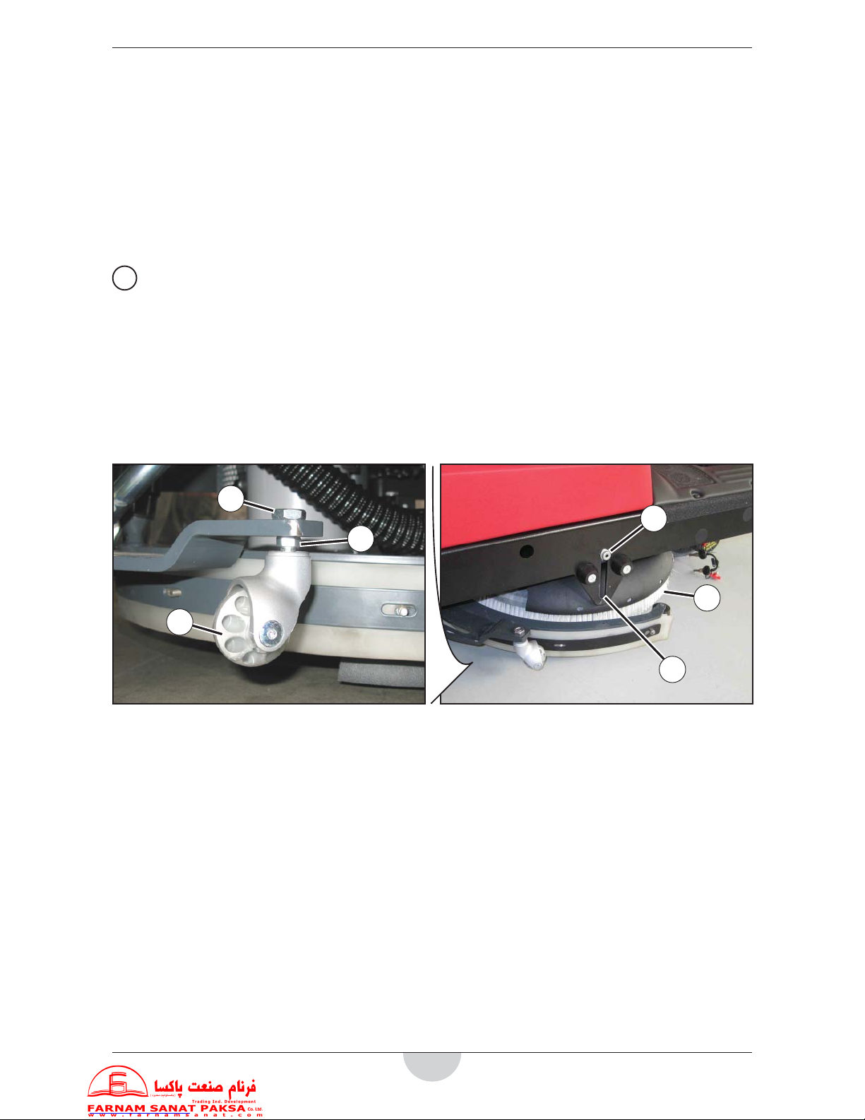
Safety functions
The machine is equipped with the safety functions described as follows.
Electromagnetic brake
The electromagnetic brake (A) is integrated in the front
wheel's traction system and keeps the machine braked
when it is turned o and when it is on but stopped.
The key (A1) locks/releases the brake.
(see chapters: “PUSHING/TOWING THE MACHINE” and
“ELECTROMAGNETIC BRAKE”.
Traction safety micro-switch
It is installed in the driver's seat in zone (B) and does not
allow any machine operation if the driver is not seated.
Emergency stop button
It is on the control and commands panel in position (C); it
is easily accessible by the operator.
It must be pressed rmly if urgently required in order to
stop all machine functions.
Turn it clockwise too release it and restore all machine
operations.
C
A
B
D
D
A1
A1
Anti-tipping tubes
These are two tubes (D) on the right and left front parts
of the frame that prevent the machine from tipping over.

13
TECHNICAL DATA
Description
S02
(Disc brush base)
Voltage 24V
Cleaning width 530 mm
Drying width 600 mm
Vacuum 1168 mm H2O
Detergent solution (or washing water) tank capacity 65 L
Disc brush rpm 175 rpm
Number of disc brushes 1
Disc brush pressure 23 Kg
Washing speed 4 Km/h
Maximum speed 5 Km/h
Maximum working angle 10%
Batteries (nr.) 2 - 118Ah
Built-in battery charger √ (Upon request)
Max. washing capacity 2120 m²/h
Autonomy (hours) based upon 118 Ah batteries 2. 30’
Detersaver √ (Upon request)
> Mixing ratio 1-5%
Machine body dimensions with squeegee and brush
(length x height x width)
1340 x 1130 x 600 mm
Basic weight of the empty machine in operation
(with 118Ah batteries, with tanks empty, without operator on board)
235 Kg
Gross weight of the ready machine
(with 118Ah batteries, with full solution tank, without operator on board)
300 Kg
Drive motor 400 W
Disc brush motor 400 W
Vacuum motor 400 W (3 stages)
Manufacturing legislation EC
Sound pressure level (A) in operating position 72.4 dB (A)

14
ACCESSORIES AND COMPONENTS UPON REQUEST
• Disc brushes in materials other than standard ones (See the chapter regarding Use the diagram for selection of
type of disc brush).
• Pad holder driving disc (A) and pad (B) (See the chapter regarding Use the diagram for selection of type of pad).
• Squeegee rubbers in materials other than standard ones (See the chapter regarding Use the diagram for selection of
type of squeegee rubbers).
• Front and rear wheels in di erent materials.
• Automatic detergent feeding system (C) (DETERSAVER based upon 5-Litre tank).
• Breakwater protection wall for the recovery water tank (antisplash feature).
• Flashing light (E).
• Kit (F) for lling the tank with detergent solution (or washing water).
• Lead batteries (WET) support
• Di erent types of batteries.
• Anti-tipping tubes (G)
B A
G
E
F
C

15
WIRING DIAGRAM 1/2
Description of electrical components
7CH4Q90A: Traction board
7CFI0000: Functions board
BA: Battery
CB: Battery charger
RC: Battery charger relay
FE: Emergency stop button
EV: Water solenoid valve (brushes)
TX2: Traction board TX serial connection
RX1: Battery charger RX serial connection
RX2: Traction board RX serial connection
K1: Brush contactor
K2: Suction contactor
K3: Brush release contactor
K4: Brush contactor NA contact
K5: Suction contactor NA contact
K6: Brush release contactor NA contact
M: Drive motor
M3: Chemical (detergent) pump
M4: Water pump
M1: Brush actuator
M2: Squeegee actuator
SP: Brush motor
ASP: Vacuum motor
SWC: Start-up key switch
SWG: Water oat
SWM: Seat micro-switch
BR: Reverse drive buzzer
LAMP: Flashing
P - SPEED REFERENCE: Accelerator potentiometer
F1: 80A midi fuse (traction)
F2: 10A blade fuse (auxiliaries)
F3: 30A midi fuse (vacuum)
F4: 40A midi fuse (brush)

16
WIRING DIAGRAM 2/2

17
PUSHING/TOWING THE MACHINE
When traction cannot be used (no batteries, at batteries, faults, etc.), the electromagnetic brake must be released as
follows to push/tow the machine:
• Insert the key (A1) in the appropriate seat (A2) and completely tighten it. During this operation, gently push
the machine back and forth to facilitate releasing the electric brake and thus be able to manually move the
machine.
Never exceed a speed of 3 Km/h during pushing/towing.
• When nished, unscrew and remove the key to apply the brakes again and bring the machine back to safe conditions. Store the key in a safe place and within reach in the event the machine has to be moved.
!
ATTENTION!
After having moved the machine and to reactivate the electromagnetic brake (A), always remember to remove
the key (A1). Check that the electromagnetic brake is reactivated by pushing the machine and verifying the
condition of the brakes.
!
ATTENTION!
Never turn the machine on with the key (A1) in released electromagnetic brake position. Release the electromagnetic brake only for the time required to move the machine.
AA1
A2
A1

18
USE
!
ATTENTION!
Adhesive labels are applied to some points of the machine, indicating:
• DANGER
• ATTENTION
• WARNING
• CONSULTATION
During reading of this manual, the operator must carefully understand the meaning of the symbols shown on the
labels. Do not cover the labels for any reason and immediately replace them if damaged.
BATTERIES
Check/Installation of batteries on a new machine
!
ATTENTION!
This machine's electrical components may become severely damaged if the batteries are not installed and
connected properly. The batteries must be installed only by quali ed personnel.
The machine must also be set, according to the batteries used: WET, GEL, AGM.
Check the batteries before installing them to make sure they are not damaged.
Disconnect the batteries connector and the battery charger's plug.
Handle the batteries carefully.
Install the protective caps of the batteries' terminals.
The machine can be supplied in one of the following con gurations:
• With batteries (WET or GEL or AGM) already assembled on the machine and ready for use.
• Batteries not supplied
Depending on the type of supply received, operate as follows.
a) Batteries (WET or GEL or AGM) already assembled on the machine and ready for use.
1. The machine is suitable for use.
b) Batteries not supplied
2. Purchase suitable batteries (See the Technical features paragraph).
Contact quali ed dealers of batteries for selection and installation.
Batteries installation/replacement
This intervention must be performed by a specialised technician; refer to the Authorized Service Center.
Setting of type of batteries installed
This intervention must be performed by a specialised technician; refer to the Authorized Service Center.

19
PRELIMINARY OPERATIONS BEFORE STARTING THE MACHINE
!
ATTENTION!
At each machine start-up, check that there are no foreign bodies between the brush base (A) and the machine,
or between the squeegee (B) and the machine, that may obstruct the brushes base and the squeegee from lifting. This check is necessary if the machine has been turned o without the brush holder base and the squeegee being lifted; when it is turned back on the brushes base and the squeegee automatically lift.
ELECTROMAGNETIC BRAKE
BRAKING is assisted by the electric brake (1). THE electric brake is integrated in the traction system of the front inwheel electric motor 2 and keeps the machine braked when it is o or when it is on but stopped. The electric brake is
equipped with a key 3 to unlock and manually move the machine when it is stopped. (for example: when the battery
is missing). Also see chapter: “PUSHING/TOWING THE MACHINE”.
!
ATTENTION!
The machine does not brake if the electromagnetic brake is released.
NEVER USE THE MACHINE WITH THE BRAKE RELEASED.
1
2
3
A
B

20
BRUSHES
Disc brushes (only for KILO disc brush base)
Proceed as follows for assembly/disassembly of the disc brush (A) on the machine provided with appropriate base:
!
ATTENTION!
Always check there are no foreign bodies between the base (J) and the machine, which can obstruct lifting of
the base, before activating the ignition key (B).
Assembly of disc brush
1. Sit on the machine seat and rotate the ignition key (B) to “I”, then wait a few seconds until the caption (D)
“Ready” appears on the display (C).
2. Wait for the brush base (J) to lift and the luminous indication (I) to turn o .
3. Rotate the ignition key (B) to “0” and extract it.
4. Position the disc brush (A) under the base (J), centring it on the coupling hub.
5. Sit on the machine seat and rotate the ignition key (B) to “I”, then wait a few seconds until the caption (D)
“Ready” appears on the display (C).
6. Press the activation button (E) to lower and rotate the brush.
7. Press the accelerator (F) lightly and only for an instant, thereby lowering the hub that will couple the brush.
If the brush is not coupled climb down from the machine and reposition the brush on the coupling hub,
which should have remained lowered (thereby easing alignment); then repeat the operations described in the
previous points 5, 6 and 7.
8. The disc brush (A) is coupled and ready for use; if necessary, turn the machine o by rotating the ignition key
(B) to “0” and extract it.
Disassembly of disc brush
1. Sit on the machine seat and rotate the ignition key (B) to “I”, then wait a few seconds until the caption (D)
“Ready” appears on the display (C).
2. Press the brush release button (G) and wait for a few seconds until the machine has released the brush after
having activated it for an instant.
3. Rotate the ignition key (B) to “0” and extract it.
4. Slightly move the squeegee (H) and recover the disc brush.
!
ATTENTION!
Use of the machine with the brush not perfectly assembled can cause injury to people and damage to equipment.
Always ensure all components have been assembled before starting the machine. Carefully
inspect the machine before using it.
A J
H
F
B
A
G
D
C
I
E

21
Selection of type of disc brush
Selection of the most appropriate brush is essential for cleaning surfaces.
You can clean more quickly with the proper brush; furthermore, the cost savings from this increase in productivity
can be substantial.
!
WARNING!
A less than optimal selection could damage the oor surfaces. If in doubt, contact the RCM representative.
NOTE!
The table below shows a selection of the most used products. For special requirements, contact the RCM representative.
SELECTION TABLE OF TYPE OF DISC BRUSHES
Type of disc brush
Union
Mix
Prolite Prolene
Aglite
Grit
500
MidGrit
240
MidLite
Grit
180
Dyna
Grit 80
Magna
Grit 46
Floors/Aggressiveness
Light
Medium
Light
Medium Medium
Medium
Strong
Strong
Ver y
Strong
Aggressive
Linoleum √√√√
Vinyl √√√√ √√
Rubber √√√
Polyole n √√
Ceramic √√√√√
Non-slip √√√√
Stone √√√√
Terracotta √√√√
Terrazzo √√√√√
Concrete √√√√√√
Marble √√
Granite √√
Floor in epoxy resin √√√
Concrete √√√√√

22
Pad holder driving disc (only for KILO versions with disc brush base)
Proceed as follows for assembly/disassembly of the pad holder driving disc (A) with pad (B) on the machine provided
with appropriate base:
Tighten/loosen the ring nut (C) to assemble/disassemble the pad (B) on the pad holder driving disc (A).
!
ATTENTION!
Always check there are no foreign bodies between the base (E) and the machine, which can obstruct lifting of
the base, before activating the ignition key (D).
Assembly of pad holder driving disc
1. Sit on the machine seat and rotate the ignition key (D) to “I”, then wait a few seconds until the caption (H)
“Ready” appears on the display (G).
2. Wait for the base (E) to lift and the luminous indication (I) to turn o .
3. Rotate the ignition key (D) to “0” and extract it.
4. Position the pad holder driving disc (A) with pad (B) under the base, centring it on the coupling hub.
5. Sit on the machine seat and rotate the ignition key (D) to “I”, then wait a few seconds until the caption (H)
“Ready” appears on the display (G).
6. Press the activation button (J) to lower and rotate the pad holder driving disc.
7. Press the accelerator (K) lightly and only for an instant, thereby lowering the hub that will couple the pad
holder driving disc.
If the pad holder driving disc is not coupled climb down from the machine and reposition the pad holder
driving disc on the coupling hub, which should have remained lowered (thereby easing alignment); then
repeat the operations described in the previous points 5, 6 and 7.
8. The pad holder driving disc (A) is coupled and ready for use; if necessary, turn the machine o by rotating the
ignition key (D) to “0” and extract it.
!
ATTENTION!
Use of the machine with the pad holder driving disc not perfectly assembled can cause injury to people and
damage to equipment.
Always ensure all components have been assembled before starting the machine. Carefully inspect the machine before using it.
Disassembly of pad holder driving disc
1. Sit on the machine seat and rotate the ignition key (D) to “I”, then wait a few seconds until the caption (H)
“Ready” appears on the display (G).
2. Press the pad holder driving disc release button (L) and wait for a few seconds until the machine has released
the pad holder driving disc after having activated it for an instant.
3. Rotate the ignition key (D) to “0” and extract it.
4. Slightly move the squeegee (M) and recover the pad holder driving disc.
A E
M
K
D
C
L
H
G
I
J
A
C
B

23
Selection of type of pad holder driving disc
Selection of the most appropriate pad is essential for cleaning surfaces.
You can perform the activity more quickly with the proper pad; furthermore, the cost savings from this increase in
productivity can be substantial.
!
WARNING!
A less than optimal selection could damage the oor surface. If in doubt, contact the RCM representative.
NOTE!
The table below shows a selection of the most used products. For special requirements, contact the RCM representative.
SELECTION TABLE OF TYPE OF PAD
FOR PAD HOLDER DRIVING DISC
Type of pad
Aggressiveness
Light
Medium
Light
Medium
Medium
Hard
Rough
Ver y
Rough
Crystallising
Polishing
Floors/Colour code
White Red Blue Green Brown Black Grey Beige
Linoleum √√√√ √
Vinyl √√√ √√ √
Rubber √√
Polyole n √
Ceramic √√√√
Non-slip √√√√
Stone √√√√
Terracotta √√√√
Terrazzo √√√√√ √√
Concrete √√√√√
Marble √√ √√
Granite √√√ √√
Floor in epoxy resin √√

24
SQUEEGEE
Proceed as follows for assembly/disassembly of the squeegee (A) on the machine:
!
ATTENTION!
Always check there are no foreign bodies between the squeegee (A) and the machine, which can obstruct lifting of the squeegee, before activating the ignition key (B).
Assembly of squeegee
1. Sit on the machine seat and rotate the ignition key (B) to “I”, then wait a few seconds until the caption (D)
“Ready” appears on the display (C).
2. Wait for the squeegee (A) to lift and the luminous indication (E) to turn o .
3. Rotate the ignition key (B) to “0” and extract it.
4. Operate on the left side of the machine to rotate the squeegee's support bracket (F) forward.
5. Position the squeegee (A) on the support bracket (F) and engage the pin (G) in the hole (H) of the squeegee.
Tighten the squeegee xing knob (I).
6. Connect the suction pipe (J) to the inlet (K) of the squeegee.
7. Rotate the squeegee unit inwards towards the machine, in a central work position.
8. The squeegee (A) is coupled and ready for use; if necessary, turn the machine o by rotating the ignition key
(B) to “0” and extract it.
!
ATTENTION!
Use of the machine with the squeegee not perfectly assembled can cause injury to people and damage to
equipment.
Always ensure all components have been assembled before starting the machine. Carefully inspect the machine before using it.
Disassembly of squeegee
1. Sit on the machine seat and rotate the ignition key (B) to “I”, then wait a few seconds until the caption (D)
“Ready” appears on the display (C).
2. Wait for the squeegee (A) to lift and the luminous indication (E) to turn o .
3. Rotate the ignition key (B) to “0” and extract it.
4. Operate on the left side of the machine to rotate the squeegee's support (F) forward and loosen its xing knob
(B).
5. Disconnect the suction pipe (J) from the squeegee's inlet (K).
6. Remove the squeegee (A) by disengaging its hole (H) from the pin (G) of its support.
D
C
E
K
H
A
B
JG
IA
I
J

25
Selection of type of squeegee rubbers
Selection of the most appropriate rubbers is essential for cleaning surfaces.
You can perform the activity more quickly with the proper rubbers; furthermore, the cost savings from this increase
in productivity can be substantial.
NOTE!
The table below shows a selection of the most used products. For special requirements, contact the RCM representative.
SELECTION TABLE OF TYPE OF RUBBERS FOR SQUEEGEE
Type of oor/Colour of
rubbers
(Polyure-
thane)
SH35
(Linatex)
SH35
(Natural
rubber)
SH33
(Natural
rubber)
SH37
(Natural
rubber)
SH40
Floor with fatty oil, acids. √
Quartz concrete oor, rough
oor and oor without joints
(without joints between the
tiles).
√
Floor with joints (with joints between the tiles); very thorough
drying of the oor.
√
Floor with joints (with joints between the tiles); average drying
of the oor.
√
Floor with joints (with joints between the tiles); light drying of
the oor.
√
Installation/removal of squeegee rubbers
See the procedure in the Maintenance chapter for installation/removal of the squeegee's rubbers.

26
TANKS
Checking the recovery water tank
Lift the cover (A) using its grip (B) and check that the recovery water tank (C) is empty, otherwise empty it as described
in the speci c paragraph “Emptying of tanks”.
Filling the detergent solution tank with water (or washing water)
The tank can be lled in one of the following ways, depending on the inlet version on the machine.
!
WARNING!
The temperature of the water inserted in the tank must not exceed 40°C (100°F).
!
WARNING!
Use a proper detergent for the type of cleaning to be carried out.
Only use low foam and non- ammable liquid detergents; suitable for the machine to be used.
During use of detergents for cleaning oors, follow the instructions and warnings on the labels.
Use suitable gloves and protective devices before handling oor cleaning detergents.
Inlet in basic version
1. Unscrew the cap (D) and pour water in through its inlet.
2. After lling, screw the cap (D).
Inlet in version with lling kit
1. Extract the lling kit (F), put the opening (G) under a water tap and ll the tank through the inlet (E)
2. After the lling stage, place back the kit (F) in its seat (E).
B
A
C
D
E
F
G

27
Installation/Filling 5-litre detergent tank (“DETERSAVER” - Upon request)
(version with automatic detergent feeding system)
!
WARNING !
Use a proper detergent for the type of cleaning to be carried out.
Only use low foam and non- ammable liquid detergents; suitable for the machine to be used.
During use of detergents for cleaning oors, follow the instructions and warnings on the labels. Use suitable gloves
and protective devices before handling oor cleaning detergents.
1. Put the tank (1) in its support (2).
2. Connect the detergent pump tube (3) to the tank’s lid (4).
3. Use the elastic strap (5) to x the tank (1) to the support (2).
4. Open the lid (4) and ll up the tank with detergent.
1
2
3
4 5

28
STARTING AND STOPPING THE MACHINE
Starting the machine
1. Prepare the machine as described in the previous paragraph.
2. Sit on the machine seat (A).
3. Rotate the ignition key (B) to “I”, then wait a few seconds until the caption (D) “READY” appears on the display
(C).
!
ATTENTION!
Do not rotate the ignition key (B) without rst sitting on the seat (A) as a safety system allows the machine to
be used only when the operator is sitting on the seat (A).
It is strictly forbidden to tamper with the seat's safety system or to simulate in any way the operator sitting on
the seat.
If the ignition key (B) is rotated without sitting on the seat, the caption “SIT DOWN” appears in zone (D) on the display
and no other machine function is available.
When the display shows indications other than those described, an intervention is required from the RCM Service
Centre.
4. Check the battery charging status by observing the percentage (E) and relative graphic (F).
Charge the batteries if necessary; see the procedure in the Maintenance chapter.
!
ATTENTION!
The machine is not suitable for use on uneven oors.
5. Go to the work area by starting the machine with your hands on the steering wheel and pressing the pedal
(G). The forward speed is adjustable from zero to its maximum set value, based on the pressure exerted on the
pedal (G).
6. To activate reverse drive of the machine when required, release the pedal (G) and when the machine has
stopped press button (H).
7. If required, use buttons (I) to adjust the ow of the detergent solution (or washing water).
8. (Upon request) If required, use buttons (J) to adjust the percentage of the washing detergent.
9. To start washing the oor, press button (L) to activate the brush(es).
10. To start drying the oor, press button (M) to activate the vacuum.
11. To start washing and drying the oor, press button (N).
12. To start polishing the oor with the pad, press button (L).
13. Start cleaning/polishing by moving the steering wheel (P) and moving the machine forwards by pressing the
pedal (G).
A
B
G
P
I
J
K
L
M N
F
CD
E
H

29
Stopping the machine
1. Release the pedal (G).
2. Press button (L) or (M) or (N) to deactivate and lift the respective active functions.
The vacuum stops a few seconds after the relative button has been pressed in order to vacuum all of the water
in the tube.
3. Rotate the ignition key (B) to “0” and extract it.
It is not necessary to lock the machine during stopping or parking as the electromagnetic brake on the front
wheel automatically brakes the machine when the accelerator is activated.
4. Empty the tanks, if necessary, as described in the speci c paragraph.
!
ATTENTION!
Do not leave the machine unattended without having removed the ignition key.
5. To immediately stop the machine in an emergency, press button (Q).
To release the emergency button (Q), rotate it clockwise until it is released from its lowered position.
MACHINE IN OPERATION
Adjustments and checks
1. Start the machine as described in the previous chapter.
2. If necessary, adjust the balance of the squeegee (T) (see the procedure in the Maintenance chapter).
3. If required, use buttons (I) to alter the ow of the detergent solution (or washing water).
4. (Upon request) If required, use buttons (J) to alter the percentage of the washing detergent.
5. If required, press the turbo button (R) to activate maximum ow of detergent solution.
6. If required, use button (K) to alter the maximum speed of the machine.
7. Periodically check the charging status of the batteries during work so as not to have at batteries in areas far
from any charging points. To charge the batteries, see the procedure in the Maintenance chapter.
8. If the recovery water tank lls during machine use, suction will automatically be stopped.
Empty the recovery water tank to restart suction (see the procedure in the speci c Paragraph).
9. Use the relative level indicator (S) to periodically check the residual quantity of detergent solution (or washing
water).
10. Empty the tank at the end of work if necessary (see the procedure in the speci c Chapter).
I
J
K
R
L
M N
Q
S
B
G
T

30
EMPTYING OF TANKS
Emptying of recovery water tank
1. Take the machine to the intended area for disposal of the recovery water, in compliance with the emission standards in force.
2. Rotate the machine's ignition key to “0” and extract it.
3. Disengage the tube (A) from its seat and lift it above the upper edge (B) of the tank until its zone (C) is free from
water, then keep it in this position and unscrew the cap (D).
4. Manually bend the tube in the zone (C) until a watertight bend (E) is obtained, then keep it bent and lower it on
the drain zone.
5. Gradually (to avoid unwanted splashes) release the bend (E) so that the dirty water ows from the tank into the
drain zone.
6. Use the grip (F) to lift the tank cover (G) and, if necessary, wash the recovery water from the tank (H) (see the
procedure in the Maintenance chapter).
7. Tighten the cap (D) and engage the tube (A) in the relative seat of the machine.
Emptying the detergent solution (or washing water) tank
1. Take the machine to the intended area for disposal of the detergent solution (or washing water), in compliance
with the emission standards in force.
2. Rotate the machine’s ignition key to “0” and extract it.
3. Open the tap (I) so that the detergent solution (or water) ows out from the tank into the drain zone.
4. If necessary, wash the detergent solution (or water for washing) tank after unscrewing the cap (P).
5. After washing the tank, close the tap (I) and screw the cap (P) back on.
!
Danger! Frost Hazard
With temperatures of 0°C or below, check and eventually fully remove water from tanks and hoses at the end
of each job or if the machine is unused for a certain period of time.
E
D
C
A
G
F
H
P
B
C
M
I

31
Emptying the 5-Litre detergent tank (Upon request - DETERSAVER)
To empty the tank 1, proceed as follows:
1. Remove the tube (3).
2. Remove the elastic strap (5).
3. Remove the tank (1) from its support (2).
4. Open the cap (4) and empty the tank in the area
designed for this purpose..
5. Clean the tube (3) and the parts of the detergent
feeding system (only in the event of prolonged inactivity of the machine).
6. Place back the tank by following the steps above
in reverse order.
1
2
3
4 5

32
Detergent solution (or washing water) tank level
• The level of the detergent solution (or washing water) in the relative tank is visible through the transparent
tube (A); the side indications (B) de ne the amount.
Recovery water tank level
• When the recovery water tank is full, the oat (C)
stops water suction; empty the tank to continue
suction (See the procedure on emptying the recovery water tank in the “Emptying of tanks” paragraph).
A
B
C

33
AFTER MACHINE USE
the following activities must be carried out at the end of work after machine use.
1. Remove and clean the brush(es) or pad holder, as described in the Maintenance chapter.
2. Empty the tanks, as described in the speci c paragraph.
3. Remove and clean the squeegee, as described in the Maintenance chapter.
4. Recharge the batteries if necessary, as described in the Maintenance chapter.
5. Store the machine in a dry and clean place with the brush(es) or pad holder and squeegee raised.
LONG DOWNTIME OF MACHINE
If the machine is not to be used for more than 30 days, you must:
1. Follow what is indicated in the “After machine use” paragraph.
2. Clean the detergent feeding system (DETERSAVER - upon request), as described in the “Emptying the 5-Litre
detergent tank” section.
3. Disconnect the connector of the batteries, as described below.
• extract the left pin (A), then rotate it a half turn to lock it in the extracted position.
• extract the right pin (B) and keep it in the extracted position.
• use the handle (C) to extract the batteries holder case (D).
• disconnect the connector (E) of the batteries.
• put the batteries case (D) in its seat, unlock it, and engage it to retainer (B) and to retainer (A).
4. Store the machine in a dry and clean place with the brush(es) or pad holder and squeegee removed or raised.
DA
B
D
C
E

34
FIRST PERIOD OF USE
After the rst 8 hours of use, you must:
• Check the tightening of the machine's fastening and connection parts.
• Check that the visible parts are intact and do not leak.
MAINTENANCE
The service life of the machine and its maximum operating safety are ensured by careful and regular maintenance.
The planned maintenance table is shown below. The schedule shown may vary depending on the particular work
conditions, to be de ned by the maintenance manager.
!
ATTENTION!
The operations must be carried out with the machine o and the batteries disconnected.
All instructions in the Safety paragraph must also be carefully read.
All planned maintenance or repairs must be carried out by quali ed personnel or be done at an Authorised Service
Centre.
Only the easiest and more frequent maintenance procedures are described in this manual, after the planned maintenance table.
NOTE!
For the procedures of the other maintenance operations foreseen in the planned maintenance table and for
the other repair procedures, contact the authorized technical service centre.
PLANNED MAINTENANCE TABLE
Operation
Daily
(after machine
use)
Monthly
(or every 100
hours)
Twice-yearly
(or every 400
hours)
Yearly
(or every 800
hours)
Cleaning the squeegee.
√
Cleaning the disc brush or pad holder driving disc.
√
Cleaning the tanks (see speci c chapter).
√
Charging the batteries
√
Checking/replacing the squeegee rubbers.
√
Cleaning the detergent solution (or washing water)
lter
√
Cleaning the detergent solution supply nozzle.
√
Checking the e ciency of the electromagnetic
brake.
√ (1)
Checking the screws and nuts are tightened.
√ (1) (2)
Checking the suction lter (Hepa).
√ (2)
Checking/replacing rotation belt of the brush(es)
√ (2)
Checking/cleaning traction chain
√ (2)
(1) :
and after the rst 8 hours of operation.
(2) : maintenance to be carried out by an authorised RCM Service Centre.

35
Check of machine operating hours
1. Sit on the machine seat.
2. Rotate the ignition key to “I”, then wait a few seconds until the caption (B) “READY” appears on the display (A).
3. Zone (C) displays the number of machine operating hours.
4. Rotate the machine's ignition key to “0” and extract it.
Cleaning the squeegee
NOTE!
The squeegee must be clean and the rubbers in good condition for the oor to be well-dried.
!
WARNING!
It is advisable to use protective gloves when cleaning the squeegee since there can be sharp debris.
1. Disassemble the squeegee, if necessary (See procedure in the speci c paragraph).
2. Wash and clean the squeegee (D); clean the compartments (E) and the recovery water passage hole (F) from
dirt and debris.
Check that the front rubber (G) and the rear rubber (H) are intact and have no cuts or tears, otherwise replace
them (see the procedure in the speci c paragraph).
3. Reassemble the squeegee if disassembled (See procedure in the speci c paragraph).
E
B
A
C
D
E
E
F
G
H

36
Check of squeegee rubbers
1. Disassemble and clean the squeegee, as described in the speci c paragraph.
2. Check that the front rubber (A) and the rear rubber (B) are intact and have no cuts and tears, otherwise replace them as described below.
Also check that the front edge (C) of the rear rubber (B) is not worn; otherwise detach the rubber and reverse
it, moving one of the other three edges (if still intact) to the front edge (C) position. Replace the rear rubber if
the other three edges are also worn, as described below.
Replacement of rear squeegee rubber
1. Disengage the safety retainer (D) and open the eccentric (E), then disengage it from the hook (I).
2. Loosen the terminal nuts (F).
3. Remove the retaining strip (G) by disengaging it from the pin nuts (F) and from the pins (H).
4. Remove the terminal strip (J).
5. Replace (or reverse) the rear rubber (B) then reassemble the removed parts, operating in reverse order to removal.
Replacement of front squeegee rubber
1. Unscrew the self-locking nuts (K) on the inside of the squeegee.
2. Remove the retaining strip (L).
3. Replace the internal rubber (A), then reassemble the removed parts, operating in reverse order to removal.
Rearrangement of the squeegee
1. Reassemble the squeegee, as described in the speci c paragraph.
2. Adjust the height of the squeegee if necessary, as described in the speci c paragraph.
B
F
F
J
I
D E
G
B
A
C
F
DE
G
H
K
L
A
H
H
K
A
L
B
37
Squeegee height adjustment
Adjustment of the squeegee height is necessary when the machine does not dry properly, leaving trails of water in
the central or external areas.
• To adjust the height, loosen the locknut (A) and adjust the height of the wheel (B) with the hex wrench (C);
tighten the locknut (A) when adjusted.
Repeat the operation on the wheel on the other side of the machine.
Cleaning the disc brush
!
WARNING!
It is advisable to use protective gloves when cleaning the disc brush because there can be
cutting debris.
1. Disassemble the disc brush if necessary (See procedure in the speci c paragraph).
2. Wash and clean the disc brush (D) from dirt and debris.
3. Reassemble the disc brush if disassembled (See procedure in the speci c paragraph).
4. The disc brush must be replaced for excessive wear when, with the brush lowered, the side pins (E) rest on the
lower ends (F) of the slots.
E
F
D
A
C
B

38
Cleaning the recovery tank
1. Take the machine to the intended area for disposal of the recovery water, in compliance with the emission
standards in force.
2. Rotate the machine's ignition key to “0” and extract it.
3. If there is recovery water in the tank, empty it (see procedure in the Use chapter).
4. Use the grip (F) to lift the tank cover (G) and wash the recovery water from the tank (H).
Remove the breakwater protection wall from its slots (P) and wash it, then put it back in its slots.
Also wash the underneath (I) of the cover and the entire perimeter gasket (J).
Check that the perimeter gasket (J) is intact: if it is damaged it may compromise correct operation of the recovery water suction.
!
WARNING!
Do not damage the oat (K)
5. Extract the recovery water inlet (L) from its seat and wash it, then put it back in its seat.
6. Extract the suction inlet (M) from its seat and clean and wash it; also clean its drain hole (N) from dirt.
Be careful that no water enters the suction inlet (M) seat (so as not to damage the vacuum motor).
Let the suction inlet (M) drip and then put it back in its seat.
7. Make all of the washing water ow from the tube (Q). Tighten the cap (R) and engage the tube (Q) in the relative
seat of the machine.
8. Close the tank cover (G).
G
F
J
I
H
P
M
K
L
N
M
R
Q

39
Cleaning the suction lter
1. Remove the vacuum motor (see procedure in the speci c paragraph).
2. Remove the suction lter (A) from the support (B).
3. Clean the suction lter with a brush and compressed air (max. 5 Bar). Replace the lter if worn.
!
ATTENTION!
Appropriately protect body parts (eyes, hair, hands, etc.) when cleaning with compressed air or water guns.
4. Assemble, following the disassembly operations in reverse.
Cleaning the detergent solution (or washing water) lter
1. With the machine's controls, lower the squeegee and the disc brush, then turn the ignition key to “0” and extract it (see Use chapter).
2. Operate on the right side of the machine to unscrew and remove the transparent cover with lter (D).
3. Remove the lter (E) from the transparent cover (F).
4. Clean the lter (E) and the transparent cover (F).
5. Replace the lter (E) in its transparent cover case (F).
6. Screw the transparent cover with lter (D) in its seat.
7. Rotate the ignition key to “I” and wait for the squeegee and the disc brush to lift, then rotate the ignition key to
“0” and extract it.
A
B
D
E
F
D

40
Cleaning the detergent solution supply nozzle to the disc brush
(KILO version with disc brush base)
1. Remove the brush (See procedure in the speci c paragraph).
2. By acting on the coupling hub (A) of the brush, unscrew the ring nut (B) and recover the nozzle (C) and the gasket
(D).
3. Clean the nozzle (C).
4. Place the nozzle (C) and the gasket (D) in their seat and then screw the ring nut (B).
5. Reassemble the brush (See procedure in the speci c paragraph).
!
ATTENTION!
Appropriately protect body parts (eyes, hair, hands, etc.) when cleaning with compressed air or water guns.
B
C
A
E
B E
C F
D
G

41
Opening/Closing of the batteries holder case and disconnection of the batteries connector
Proceed as follows to open the case and disconnect the connector:
1. Rotate the ignition key to “0” and extract it.
2. Operate on the rear side of the machine to extract the left pin (A), then rotate it a half turn to lock it in the extracted position.
3. Extract the right pin (B) and keep it in the extracted position.
4. Use the handle (C) to completely extract the batteries holder case (D), then engage the pin (B) on the relative
locking hole of the batteries case.
5. Disconnect the connector (E) of the batteries.
Proceed as follows for connection and closure of the case:
1. Reconnect the connector (E) of the batteries.
2. Disengage the pin (B) and carefully put the batteries case in its seat, then engage the pin (B) to the batteries
case.
3. Unlock and engage the pin (A) to the batteries case.
DA
B
D
C
E

42
Charging the batteries
!
WARNING!
Keeping the batteries charged lengthens their life.
!
WARNING!
When the batteries are at, make sure they do not remain in this condition for long as this would shorten their
life.
Check the battery charging status at least once a week!
!
WARNING!
For machines without on-board battery charger, use a battery charger suitable for the type of batteries installed.
!
ATTENTION!
Charging lead batteries with liquid acid (WET) produces highly explosive hydrogen gas. Only charge in areas
that are well-ventilated and far from open ames.
Do not smoke during battery charging.
Keep the batteries holder case in the extracted position during battery charging.
!
ATTENTION!
Be very careful when charging the lead batteries with liquid acid (WET) as small quantities of liquid could leak
from the batteries. This liquid is corrosive; if it comes into contact with the skin or eyes, wash abundantly with
water and immediately contact a doctor.
Charging the batteries, for machines with no on-board battery charger
(Using an external battery charger)
1. Take the machine to a suitable area to charge the batteries.
2. Open the batteries holder case and disconnect the batteries connector (see procedure in the previous paragraph).
3. Only for lead batteries (WET):
• check the correct level of the electrolyte inside the batteries (E); restore it through the cap (F) if necessary.
• leave all caps (F) open for subsequent charging.
• clean (if necessary) the upper surface of the batteries.
4. Check the suitability of the battery charger to be used by referring to its instructions. The nominal voltage of
the battery charger must be equal to 24V.
5. After disconnecting the batteries connector (G), connect the connector (H) to the external battery charger.
6. Connect the battery charger to the electrical mains.
The batteries start charging.
7. When they are charged, disconnect the battery charger from the electrical mains and from the batteries connector (H).
8. (only for lead batteries (WET)) Check the correct level of the electrolyte inside the batteries and close all the
caps (F):
9. Connect the batteries connector and close the batteries holder case (see procedure in the previous paragraph).
10. Charging is complete.
G
H
F
G
H
E

43
Charging the batteries, for machines with on-board battery charger (upon request)
1. Take the machine to a suitable area to charge the batteries.
2. Open the batteries holder case (see procedure in the previous paragraph) but do not disconnect the batteries
connector (D).
3. Only for lead batteries (WET):
• Check the correct level of the electrolyte inside the batteries (E); restore it through the cap (F) if necessary.
• Leave all caps (F) open for subsequent charging.
• Clean (if necessary) the upper surface of the batteries.
4. Connect the connector (G) to the electrical mains, after having checked that the mains nominal voltage is the one foreseen for charging the machine (Refer to the machine's technical data plate).
The batteries start charging.
NOTE!
When the battery charger is connected to the mains, all machine functions are automatically excluded.
5. Charging is complete when “100 %” is shown on the zone (H) of the display and the notches of the zone (I) are
all full.
6. Disconnect the electrical connection (G) from the mains.
7. Only for lead batteries (WET ) Check the correct level of the electrolyte inside the batteries and close all the caps (F).
8. Close the batteries holder case (see procedure in the previous paragraph).
9. Charging is complete.
E
F
G
D
H I
E
F

44
Check/Replacement of fuses
1. Open the batteries holder case and disconnect the batteries connector (see procedure in the previous paragraph).
2. Remove the screw (F) with a crosshead screwdriver and the panel (G) by taking it by the handle (as shown in the
photo) and disengaging it from its lower pins (H).
3. Check/replace the fuse:
• 10A fuse, for auxiliary services (I) protection
!
ATTENTION!
Request intervention of a quali ed technician or of the Service Centre for replacement of the other fuses.
4. Insert the panel (G) by engaging it in its lower pins (H).
5. Screw back the screw (F).
6. Extract the batteries case again and connect the batteries connector.
7. Connect the batteries connector and close the batteries holder case (see procedure in the previous paragraph).
I
G
H
F

45
Disassembly/assembly of the disc brush
• See the procedure in the “Use” chapter, “Preliminary operations before starting the machine” paragraph.
Disassembly/assembly of pad holder driving disc
• See the procedure in the “Use” chapter, “Preliminary operations before starting the machine” paragraph.
Disassembly/assembly of squeegee
• See the procedure in the “Use” chapter, “Preliminary operations before starting the machine” paragraph.
Disassembly/assembly of vacuum motor
Proceed as follows to disassemble the vacuum motor:
1. If available, place the machine on a raised platform, otherwise place it on a level oor.
2. With the machine's controls (as foreseen in the Use chapter), lower the brush and the squeegee, then rotate the
ignition key to “0” and extract it.
3. Open the batteries holder case and disconnect the batteries connector (see procedure in the previous paragraph).
4. Operate on the left side of the machine to unscrew the screws (A).
5. After having disconnected the electrical connector (C) of the vacuum motor, remove the support unit with the
vacuum motor and lter (B).
6. At the bench remove the soundproof gasket (D).
7. Cautiously remove the vacuum motor (E) by disengaging it from the suction lter (F).
Proceed as follows to assemble the motor:
• Reassemble, following the disassembly operations in reverse.
A
A
B
B
C
D
E
F

46
TROUBLESHOOTING
Problem Probable cause Solution
No luminous indicator lights up on
the panel; the motors do not work.
Battery connector (8 page 10) disconnected.
Connect connector.
Batteries at. Charge the batteries.
The emergency stop button (2 page
11) has remained pressed.
Release it.
Suction of the recovery water is insu cient.
Squeegee (9 page 10) dirty or squeegee rubbers worn or damaged.
Clean the squeegee or turn/
replace the rubbers.
Tank cover not closed
properly or gasket (J page 41) not
working.
Close the cover properly. Clean/replace the gasket.
There is no recovery water suction.
Recovery water tank full.
Empty the tank.
Hose (J page 26) disconnected from
the squeegee.
Connect hose.
Insu cient ow of detergent
solution (or washing water) to the
disc brush.
Detergent solution (E page 42) (or
washing water) lter dirty.
Clean lter.
Detergent solution (or washing water) outlet nozzle dirty.
Clean nozzle.
Detergent solution (or washing water) tank dirty.
Clean the tank.
No ow of detergent
solution (or washing water) to the
disc brush..
Detergent solution (or washing water) tank empty.
Fill the tank.
Detergent solution (E page 42) (or
washing water) lter clogged.
Clean the lter.
Detergent solution (or washing water) outlet nozzle clogged.
Clean the nozzle.
Insu cient/no ow of
washing detergent to the disc
brush. (For machine with DETER-
SAVER “upon request” detergent
feeding system).
Detergent ow percentage (%)
set too low
Increase percentage.
Detergent feeding system
clogged.
Clean the system.
The squeegee leaves dirty marks on
the oor.
Debris under the squeegee rubbers. Clean the squeegee.
Squeegee rubbers worn, chipped or
torn.
Turn the rubbers or replace them.
The squeegee does not lie correctly.
Adjust the height of the wheels
supporting the squeegee.
The disc brush does not clean.
Brushes excessively worn and do not
touch the oor, check:
Check the pins (E page 39) or the
pins (C page 40).
Replace the brushes.
For further information, contact RCM Service Centres.

47
SCRAPPING
!
ATTENTION!
This machine must not be disposed of with other domestic waste at the end of its life cycle.
To prevent any harm to the environment or to human health from uncontrolled waste disposal, we recommend the user to separate this product from other types of waste and recycle it responsibly to promote the
sustainable reuse of material resources.
Scrap this machine at an authorised demolition company.
Before scrapping the machine, remove and separate the following materials and send them to a waste collection
centre in compliance with the environmental health standards in force.
• Batteries
• Disc brush
• Tubes and parts in plastic
• Electrical and electronic parts (*)
(*): Especially for the scrapping of electrical and electronic parts, refer to the RCM area o ce.
 Loading...