


1/10 Scale 4WD Electric off-road buggy
maintain and replace the spare parts,please keep and take it for reference.
The user who is not familar with the assembling,please contact with the
wholesaler,nominated model shops and the Special after-sale service
outlets.
This manual expatiate the structure of the model. In order to better
B - 10 E S pecification s
Leng th:
4 1 7m m
Width: 25 0 / 25 2 m m
Heig ht: 1 51m m
Whee l Base: 2 90m m
Gear R atio:9 .47:1
Tire Typ e: Φ8 7 x3 4 m m ( F ) Φ 8 7x39 m m ( R )
The Ma x. Ground Clearance: ( F/ R ):2 9 / 3 0m m
The act ual v ersio n is su bject t o the r eal standa rd. It woul d be va ried
becau se of d iff erent v ers ions.
Manual
B R U S H LE S S /B R U S H E D
B-10E
B-10E Specific ations
Leng th:
Width: 250/252mm
Dimensiones: 417mm x 250/252mm x 151mm
Heig ht: 151mm
Distancia entre ejes: 290mm
Whee l Base: 290mm
Ruedas (D/T): ø 87x34mm / ø 87x39mm
Gear R atio:9.47:1
Altura del suelo (D/T): 29/30mm
Tire Typ e: Φ87x34mm(F) Φ87x39mm(R)
The Max. Ground Clearance: (F/R):29/30mm
This manual expatiate the structure of the model. In order to better maintain and replace the spare parts, please keep and take it for reference. The
user who is not familar with the assembling,please contact with the wholesaler,nominated model shops and the Special after-sale service outlets.
The spare parts,appearanc e of this model will be tiny re vised and changed befor e totally upgrade into a ne w
vers ion,ZD reserve this rig hts,and no further noti ce.
The actual version is subject to the real standard.It would be varied because of different versions.
417mm
R
Scale
1:10
Ready To Run
This manual expatiate the structure of the model. In order to better
maintain and replace the spare parts,please keep and take it for reference.
The user who is not familar with the assembling,please contact with the
wholesaler,nominated model shops and the Special after-sale service
outlets.
The act ual v ersio n is su bject t o the r eal standa rd. It woul d be va ried
becau se of d iff erent v ers ions.
Electric
4WD
2.4G
Radio

1. Don't operation the models close to open fires or near heat source.
2. Operation must be in the open and dry site .
3. The thunderstorm weather is forbidden to operate this product.
4. Away from the high voltage cables.
5. Some of the parts will be exothermic or burning after operated.
6. Please do not use hand or foreign body contact activities of the parts before cut off
the power supply, .
7. During the operation, if foreign matter or liquid get into eyes, please timely with
plenty of water flush eyes, and immediately consulting professional doctor. As the
body is injured, please seek imm
ediate medical attention.
8. Keep out of the reach of children, this is not toy, strongly suggest adult supervision.
9. Placed in ventilated and dry place, do not use, take the battery out.
10.The product items do not diet or swallowed.
SAFETY GUIDELINES
3
B-10E
IN T R ODU CE
B - 1 0 E
INTRODUCE
Thank you fo r ch oo sing the ZD racing series products. Our company take th e ta rg et of offering the t op
Than y k o f u o c r hoosin t g h MCR e s er ie p s roduc ts O . u c r ompan t y ak t e h t e arge o t o f fferin t g h t e o p
quality an d be st service. Th ro ugh attending the competitions and repeated testing the p ro ducts,
qualit a y n b d es s t ervice . Throug a h ttendin t g h c e ompetiti on a s n r d epeate t d estin t g h p e roducts ,
constant ly e nhancing our experience,then further improvin g th e de sign and quality control. Only for
constant l e y nhancin o g u e r xp erience,the f n urthe i r mprovin t g h d e esig a n n q d u al it c y o ntrol O . nl f y o r
showin g th e gr eat performance products. This manual including all the important mat te r be fore operating
showin t g h g e rea p t erformanc p e roducts . Thi m s anua i l ncludin a g l t l h i e mportan m t atte b r e for o e peratin g
the car. We advise studying and k no wi ng the control system before assembling or playing it . As we ll a s
th c e a W .r a e dvis s e tudyin a g n k d nowin t g h c e ontro s l yste b m efor a e ss emblin o g p r layin i g t . A w s el a l s
the furthe r up gr ade and maintenance. Please feel free t
th f e urthe u r pgr ad a e n m d a in tenance P . leas f e ee f l re t e c o onsul o t u a r uthorize d d eale ,r nominate m d ode l
shop or spec ia l after-sale service station if any question refer to the pla y or u se. Our website
sho o p s r pecia a l fter-sal s e er vic s e tatio i n a f n q y ue st io r n efe t r t o h p e la o y u r se O . u w r ebsite
is:www.xi ng yaohua.com. We a re wholeheartedly for your service.
is se.ocitimcr.www//:ptth : W a e r w e holeh ea rt edl f y o y r ou s r ervice.
QUALITY ASSURANCE
Our compan y ta ke the fully responsibility to the quality defect during th e ma nufacturing process.
This assur an ce is only subject to the product only and its spare parts.
These situat io n be low are not included:
The breaka ge c aused by using,assembling or adjustment.
The other br ea kage not related to the quality itself.
o consult ou r au th orized dealer,nominated model
IMPORTANT STATEMENT
The Mode l Car is not a toy. It is the casual item combine a lot of high tec hnology produ ct s. If using
improp er may brin g serious damage. Please read the manual de ta il ed before using, and keep your se lf
safe.
Attentio n: Any ope ra tion of the Model car,the manufacturer and dealers are incapable of take the
respon si bility of the accidents caused by wear out or abnormal asse mb le.
This product is p ro vided to those who have o pe ra tion remote control model c ar experience or a
technica l personnel in the guidance of the local legal field, in ha s to ensure the saf e and correct operation
under th e condition of use.Our company wi ll not accept an y operation and use the control o n any
performa nc e and safety responsibility
The RC products are belong to consum ab le goods,if disasse mb le,it may caus
use of goods caused by bad or not satisfied, will not be able to replace or return, such as in case of
operatio n maintenance problems, t he company designat ed national distribut or model shop a nd special
after-sa le s ervice store will provide technical guidance, and s pe cial parts supply services.
e the spare parts loss,Any
Warning: because of the neglect of these operating ins tr uctions, and use wrongly may cause
property dam ag e or serious injury.
Note: beca us e of the neglect of these operating instructions, and u
dangerou s.
Ban: in any pr oh ibited environment, do not try to operation.
se wrong ly c ou ld be
2
2

SAFETY GUIDELINES
1. Don't operation the models close to open fires or near heat source.
2. Operation must be in the open and dry site .
3. The thunderstorm weather is forbidden to operate this product.
4. Away from the high voltage cables.
5. Some of the parts will be exothermic or burning after operated.
6. Please do not use hand or foreign body contact activities of the parts before cut off
the power supply, .
7. During the operation, if foreign matter or liquid get into eyes, please timely with
plenty of water flush eyes, and immediately consulting professional doctor. As the
body is injured, please seek imm
ediate medical attention.
8. Keep out of the reach of children, this is not toy, strongly suggest adult supervision.
9. Placed in ventilated and dry place, do not use, take the battery out.
10.The product items do not diet or swallowed.
3
3

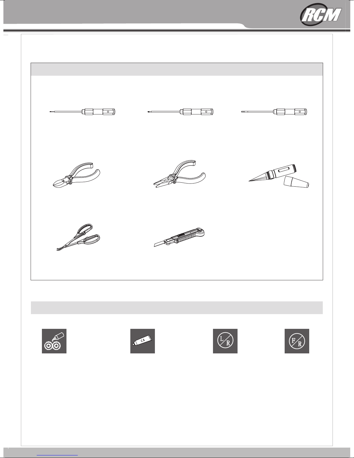
2.5 Assorted Screwdrivers
8F5-200250-00-00
2.0 Assorted Screwdrivers
8F5-300200-00-00
1.5 Assorted Screwdrivers
8F5-300150-00-00
Hobby Scissors
6Y7-000001-00-07
Hobby Knife
6X0-000028-00-00
Wire Cutters
6Y7-000001-00-00
Needle Nose Pliers
6T4-000096-00-00
Reamer
Recommended maintenance tools(not included)
8PT-040001-71-00
Symbols used throughout the instruction manual
Assemble both
L/R sides
Assemble both
F/R sides
Apply CA glue
(not included)
All kinds of grease
(not included on the
products)
5
EB10
5
5000 mAh 30C
2
Li-po battery
EB10
2
4
Recommended maintenance tools(not included)
1.5 Assorted Screwdrivers
8F5-300150-00-00
Wire Cutters
6Y7-000001-00-00
Hobby Scissors
6Y7-000001-00-07
2.0 Assorted Screwdrivers
8F5-300200-00-00
Needle Nose Pliers
6T4-000096-00-00
Hobby Knife
6X0-000028-00-00
2.5 Assorted Screwdrivers
8F5-200250-00-00
Reamer
8PT-040001-71-00
Symbols used throughout the instruction manual
All kinds of grease
(not included on the
products)
Apply CA glue
(not included)
Assemble both
L/R sides
5
5
Assemble both
F/R sides

2
3
4
1
5
6
8
9
10
7
11
12
Tail
13
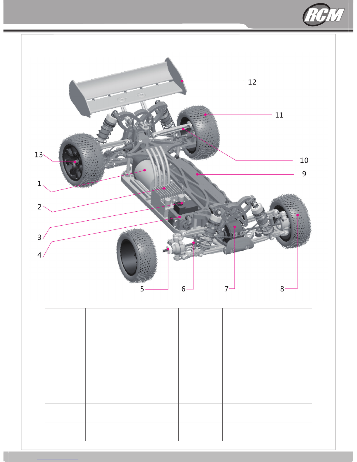
Brushed Motor
Brushed ESC
Receiver
Servo
Gear Box
Front Ti re
Battery
Drive Shaft
Rear Tir e
Locknut
Wheel Hub
Drive Shaft
B-10E Brushed Car
1
2
3
4
5 6 7 8
9
10
11
12
13
7
B-10E
13
1
2
B-10E Brushless Car
EB10 Brushless Car
12
11
10
9
3
4
Brushless Motor
1
2
3
4
5
Brushless ESC
Receiver
Servo
Wheel Hub
5 6 7 8
Front Ti re
8
9
10
11
12
Battery
Drive Shaft
Rear Tir e
Tail
6
7
Drive Shaft
Gear Box
Locknut
13
6
6
B-10E Brushed Car
EB10 Brushed Car
12
11
13
1
2
3
4
10
9
5 6 7 8
1
Brushed Motor
8
Front Ti re
2
3
4
5
6
7
Brushed ESC
Receiver
Wheel Hub
Drive Shaft
Gear Box
Servo
9
10
11
12
13
7
7
Battery
Drive Shaft
Rear Tir e
Tail
Locknut

MID
1 2 3
4 5 6
7 8 9
Racing Steps
Open the cap of the r ad io
Put 4 AA batteries in to t he battery tank
(Please note th e Po sitive and Nega ti ve )
Note: 1. In order t o ge t the better cont rol effect, w e recommend you to us e AA1.5 V alkaline bat teries (not inc lu ded in the
product), the r at io of 1.2 V recharg ea ble battery effect is better. 2. Battery if ins ta llation error s of t he pole, or long ti me
no management wil l lead leakage.3. D o not use the old bat te ry and new batter y hy brid together. 4 .If long time idle, d o not
leave the batte ry i n the remote cont ro l.
Racing Operation Steps
Cover the cap of th e ra dio
Properly inst a
lled antenna tu be pu t the battery into th e battery tank cover the batte ry b ox
Adjust the thro tt le, steering ve rn ier
adjustment kn ob b utton to median
(MID) directi on . big/small rud de r
Angle knob butt on t o 120%
Be sure to first op en t he remote contr ol p ower, and then ope n th e model car
power supply, switch on the pow er, t he motor delive ri ng a diz ~ diz ~ ~ ~ sounds ,
it means the moto r fo r standby state . open radio button , the motor will be gi n to run.
Finish racing note
Turn off the E SC a nd disconnect
the power plug.
Turn off the r ad io
Put out the batte ry
B-10E
10
C H A R G IN G T H E B A T T E R Y P A C K
1
2
3
A Once the battery r ea dy to be charged, first plug the AC quick c ha rger into the outlet of AC power
source, an d th en connect the battery input/output harness to the charger.
B. Continu ed t o monitor the battery as it is being charged. As soon as the battery is full y ch arged,
discon ne ct the battery. from th e ch ar ger plug (Over-charging or charging incorrectly usi ng i nadequate
chargers m ay c ause the battery pack to become dangerouslyhot).
C. For best re su lts, let the battery pack cool before charging. Heat may preven t th e battery pack from
chargi
ng to full cap ac ity and also decreases the performance of the battery.
.
Lithium Po ly mer (Li-Po) batteries are becoming popular for use in R/C m od els due to their compact size,
high ene rg y density, andhig h- current output. However, these types of batteries require sp ec ial care and
handli ng p rocedures for long life and safe operation.
A F TE R C H A R G E T IME E X P IR E S , D I S C ON NE C T
B AT TE R Y P L UG F R O M C H AR G E R P L U G .
P L UG I N TO A C O U TL E T.
C O NN E C T B AT T E R Y P L U G
T O D C O UT LE T P L UG F R O M C H A R G E R .
L iP o B A T T E R IE S
CHARGING THE BATTERY PACK
A Once the battery r ea dy to be charged, first plug the AC quick c ha rger into the outlet of AC power
.
source , an d th en connect the battery input/output harness to the charge r.
B. Continu ed t o monitor the battery as it is being charged. As soon as the battery i s fu ll y charged,
discon ne ct the battery. from th e ch arger plug (Over-charging or charging incorrect ly u sing inadequate
charge rs m ay c ause the battery pack to become dangerouslyhot).
C. For best re su lts, let the battery pack cool before charging. Heat may prev en t the battery pack from
chargi ng t o fu ll capacity and also decre
1
PLUG INTO AC OUTLET.
ases the per fo rmance of the battery.
3
CONNECT B ATTE RY PLUG
TO DC OUT LET PLU G FROM CH ARGER .
2
AFTER CHA RGE TIM E EXPIR ES, DIS CONNE CT
BATTERY PLUG FRO M CHARG ER PLUG .
LiPo BATTERIES
Lithium Po ly mer (Li-Po) batteries are becoming popular for use in R /C m odels due to their compact size,
high ene rg y density, andhig h- current output. However, these types of batteries requir e sp ec ial care and
handli ng p rocedures for long life and safe operation.
Warning: Lithium Polymer (Li-Po) batteries are int en de d only for advanced users that are educated on
Wa r ni ng : Lithium Polymer (Li-Po) batteries are inten de d only for advanced users that are educated on
the risks as so ciated with Li-Po battery use. THUNDER TIG ER/ACE RC does not recommend
Important: D o no t use NiCd/Ni-MH battery chargers for Li-PO batteries . If y ou d o not use a special
Impo
the risks as so ciated with Li-Po battery use. www.rcmitico.es does n ot r ec ommend
that anyon e un der the age of 16 use or handle Li-Po battery packs without the sup er vision of a
that anyon e un der the age of 16 use or handle Li-Po battery packs without the sup er vision of a
knowle dg eable and respo
knowle dg eable and responsible adult.
r ta nt: Do not use NiCd/Ni-MH battery chargers fo r Li -P O batteries. If you do not use a special
charge r fo r Li -PO battery,they wi ll b e damaged.
charge r fo r Li -PO battery,the y wi ll b e damaged.
nsible a du lt.
Please not e! C on sumers for use or installation of lipo battery in the remote control model be lo ng s
and cause any Di re ct or indirect damages, our company will not bear any legal liability.
8
9

B-10E
Racing Operation Steps
Racing Steps
1 2 3
Open the cap of the r ad io
Note: 1. In order t o ge t the better cont rol effect, w e recommend you to us e AA1.5 V alkaline bat teries (not inc lu ded in the
product), the r at io of 1.2 V recharg ea ble battery effect is better. 2. Battery if ins ta llation error s of t he pole, or long ti me
no management wil l lead leakage.3. D o not use the old bat te ry and new batter y hy brid together. 4 .If long time idle, d o not
leave the batte ry i n the remote cont ro l.
Put 4 AA batteries in to t he battery tank
(Please note th e Po sitive and Nega ti ve )
Cover the cap of th e ra dio
4 5 6
Properly inst a
lled antenna tu be pu t the battery into th e battery tank cover the batte ry b ox
MID
7 8 9
Adjust the thro tt le, steering ve rn ier
adjustment kn ob b utton to median
(MID) directi on . big/small rud de r
Angle knob butt on t o 120%
Finish racing note
Turn off the E SC a nd disconnect
the power plug.
Be sure to first op en t he remote contr ol p ower, and then ope n th e model car
power supply, switch on the pow er, t he motor delive ri ng a diz ~ diz ~ ~ ~ sounds ,
it means the moto r fo r standby state . open radio button , the motor will be gi n to run.
Turn off the r ad io
10
9
Put out the batte ry
The adjustment of Radio
Speed cont ro l over heats
Car has a prob le m on power
If you have trouble starting or keeping your love car running, here's a
quick checklist of what to look for first.
TROUBLESHOOTING
Car dies or sl ow s
Car is glitc hi ng
Motor is ove rh eats
No power
No throttl e
No steerin g
Revers in g
Descript io n
Goes backw ar ds when you pull the
trigger or g oe s right when turning the
wheel le ft
Servo no t pl ug ged in
Locked up st ee ring linkage
Servo fail ur e
Motor not pl ug ged in
Motor fail ur e
No throttl e, o nl y steering
Motor keep s ru nning
Gear mesh is t oo t ig ht
Battery is d is charged
Che
ck for loose wires, dead radio batteries
or loose crystals.Check motor capacitors,
losse wires or crystals.
Check thro tt le / steering reversing
switches o n tr ansmitter
Plug ser vo i nto ESC unit
Free up stee ri ng linkage
Replac e se rv o
Plug motor i n
Replac e mo to r
A-T-L function works;turn off the vehicle
first and fo ll ow the guide to turn on the
radio. (Ra di o first, vehicle second!!!)
Check if the t hr ottle trim knob is in neutral
position .
Charge b at te ry
Charge b at te ry
Let motor co ol a nd check recommended
gearin g fo r mo tor type. Reset g
ear mesh
Let it cool an d tr y la ter
Solution
Problem
13
First open the t ra nsmitter powe r,c onnect the Lipo battery power output plugs and electronic g overnor
power input plug. Then turn on the ESC. (The 1 ps 7.4 V battery on t he car,when turning on t he power
supply must pay attention to the positi ve and ne ga ti ve pole), hearing the tone or the power indicator
light is lit .
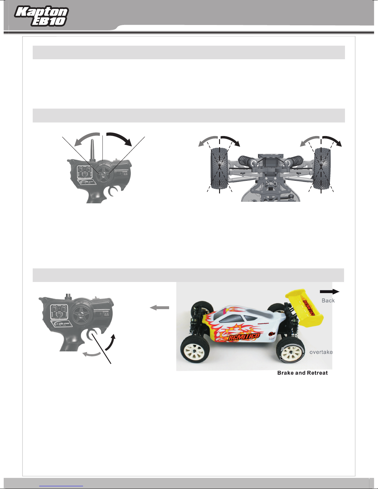
Steering operation guide
turn left
1) slo wly rotating around the s te ering wheel, the car
will be slow to the right or to the left accordingly (when
there is no c
control ST direction and rud de r sw itch).
2) when the cars can't run straight, you can adjust te
directio n of the remote con tr ol on the median knob,
until the ve hi cle can run straight.
onsisten t please toggle on the remote
turn right
Throttle operation
overtake
turn left
Center Positi on Center Positi on
◆
◆
turn right
Adjust the Medi an t rimming to keep t he
front wheel in th e ce nter position
When testing th e di version of the ca r,p lease
keep the front wh ee l hang in the air.
turn left
turn right
Back
overtake
(1) Slowly p re ss the throttle operation lever, the cars will be slow to over ta ke.
(2) When the throttle leve r to
action, the car will ma ke back action. when there is not consistent, please strike on th e remote control of
TH (oil Door ) an d rudder switch.
(3) When the throttle machine didn't do any action, wheels ap pe ar to be automatic for wa rd or b ac kw ard
rotation ,y ou can adjust the throttle median knob on the remote control, u nt il the car static.
(4) When pr ess the throttle lev er, but the car no any reaction (perhaps with diz d iz diz ~ ~ ~ ~ th
sound) , but the rudder function is normal, it shows that the car drive syst em get into safe mode, now
please cor re ct TH (throttle) a k no b, u ntil the gas operation normal or buzzing sound stop.
Brake and Retre at
push up, the car will be brakin g action. w he n making brake - median - brake
10
Brake and Retre at
overtake
e buzzing

TROUBLESHOOTING
If you have trouble starting or keeping your love car running, here's a
quick checklist of what to look for first.
Descript io n
Car dies or sl ow s
Car is glitc hi ng
Motor is ove rh eats
No power
No throttl e
Problem
Speed cont ro l over heats
Car has a prob le m on power
Gear mesh is t oo t ig ht
Battery is d is charged
Motor not pl ug ged in
Motor fail ur e
No throttl e, o nl y steering
Motor keep s ru nning
Solution
Let it cool an d tr y la ter
Che
ck for loose wires, dead radio batteries
or loose crystals.Check motor capacitors,
losse wires or crystals.
Let motor co ol a nd check recommended
gearin g fo r mo tor type. Reset g
Charge b at te ry
Charge b at te ry
Plug motor i n
Replac e mo to r
A-T-L function works;turn off the vehicle
first and fo ll ow the guide to turn on the
radio. (Ra di o first, vehicle second!!!)
Check if the t hr ottle trim knob is in neutral
position .
ear mesh
No steerin g
Revers in g
Servo no t pl ug ged in
Locked u p st ee ring linkage
Servo fail ur e
Goes backw ar ds when you pull the
trigger or g oe s right when turning the
wheel le ft
13
Plug ser vo i nto ESC unit
Free up stee ri ng linkage
Replac e se rvo
Check thro tt le / steering reversing
switches o n tr ansmitter
11

3.REAR GEAR BOX ASSEMBLY
4.FRONT LOWER SUSPENSION ARM ASSEMBLY
7181
7247
7180
7181
7248
7178
7182
7180
7247
7179
0.10m m
7182
50mm
50mm
51mm
7181
7181
7251
x2
x2
7271
7270
x2
x1
7272
x1
7248
x6
7247
1:1
7175
26.2m m
7176
7175
7272
7177
7177
7251
7271
7271
7270
7270
7170
7175
M3X10 P an Se lf- tapping Sc rew S et
M3X12 F lat H ead S elf-tapp ing
Screw S et
M3X20 F lat H ead S elf-tapp ing
Screw S et
1:1 Scale
Ball bear ing φ15 x10x4
Ball bear ing φ10 x5x4
E butto n φ2.5x0. 4
Add app rop ria te
amoun t of oi l
Susp. Ar m Hin ge
Pin Bra ce fr ont
3x30m m Hin ge Pi n
Susp. Ar m Hin ge
Pin Bra ce fr ont
15
with a ga p of 0. 10m m
B-10E
1:1 Scale
7244
M2x10 S ock et Ca p Screw
7276
φ10xφ5.5x0.3 Washers
7275
φ8xφ5.1x0.3 Washers
x8
x2
x6
x4
1.DIFFERENTIAL ASSEMBLY
Add app rop ria te
7244
amoun t of oi l
7174
7171
7172/ 7279
7275
7171
7171/ 7280
13T大伞齿
7171
7172
7279
7173
Add app rop ria te
amoun t of oi l
7173
7173
7271
7172
7276
7173
7172
Add app rop ria te
amoun t of oi l
7275
7272
E button φ2.5x0. 4
M3X10 P an Se lf- tapping Sc rew S et
Ball bear ing φ15 x10x4
Ball bear ing φ10 x5x4
Set Scr ew M4 x4
E button φ2.5x0. 4
7251
7271
7270
7260
7272
7173
7173
7170
x2
x2
x2
x1
x1
2.FRONT GEAR BOX ASSEMBLY
1:1
7171
Add app rop ria te
amoun t of oi l
7251
28mm
7175
7271
7177
7175
7271
7270
7175
7175
7272
7177
7171
7172
7279
7270
7174
7260
Put a lit tle
screw g lue
7176
The scr ew sh oul d
be lock ed in t he
plani met ric p osition
of shaf t
12
14

1:1 Scale
x2
7251
M3X10 P an Se lf- tapping Sc rew S et
x2
7271
Ball bear ing φ15 x10x4
x2
7270
Ball bear ing φ10 x5x4
x1
7272
E butto n φ2.5x0. 4
3.REAR GEAR BOX ASSEMBLY
26.2m m
7175
1:1
7175
7175
7272
7271
7251
Add app rop ria te
amoun t of oi l
7177
7271
7170
7176
7270
7177
7270
x1
7248
M3X20 F lat H ead S elf-tapp ing
Screw S et
x6
7247
M3X12 F lat H ead S elf-tapp ing
Screw S et
4.FRONT LOWER SUSPENSION ARM ASSEMBLY
7247
7180
7182
3x30m m Hin ge Pi n
7181
Susp. Ar m Hin ge
Pin Bra ce fr ont
7181
Susp. Ar m Hin ge
Pin Bra ce fr ont
7248
7178
7247
7179
7182
7180
7181
with a ga p of 0. 10m m
0.10m m
7181
50mm
50mm
51mm
15
13

7.THE ASSEMBLY OF FRONT ANTI-SWAY BAR
7192
7258
7192
7192
7192
7250
7192
7192
128.6 1mm
7253
7192
7259
7192
7277
7194
7192
7259
7192
7193
7250
7193
7277
7193
7192
7191
7267
7191
7194
7189
136.7 8
7189
10253
7193
7258
7194
7191
7267
8.THE ASSEMBLY OF REAR ANTI-SWAY BAR
2.00m m
0.00
0.00
2.00
x2
7194
x2
7259
7258
x2
x2
7250
x2
7253
7277
x2
x2
7259
7258
x2
x2
7250
x2
7253
7277
x2
7278
7268
x2
7267
x4
7194
x2
7270
x2
x4
1:1
3mm
1mm
1:1
7270
7190
7270
7189
7190
7278
7188
7268
Set Scr ew M3 x3
M3X6 Pa n Sel f-t apping Scr ew Se t
M3X14 P an Se lf- tapping Sc rew S et
Set Scr ew M3 x10
Set Scr ew M3 x3
M3X6 Pa n Sel f-t apping Scr ew Se t
M3X14 P an Se lf- tapping Sc rew S et
φ8xφ3.2x0.5 Washers
φ8xφ3.2x0.5 Washers
Φ7.5xΦ5.1x2.1
Rear Wheel Shaft Washers
1:1 Scale
Front Swa y Bar
right
Left
Rear Sway B ar
Set Scr ew M3 x10
Front Low er Susp ensio n Pins
Rear Lowe r
Suspens ion Pin s
Ball bear ing φ10 x5x4
φ2x11 Pin S et
φ2x10 Pin Se t
Add app rop ria te
amoun t of oi l
Anti- rol l bar i s installe d up
the tra nsm iss ion shaft.
Anti- rol l bar i s installe d up
the tra nsm iss ion shaft.
17
B-10E
5.REAR LOWER SUSPENSION ARM ASSEMBLY
1:1 Scale
7247
M3X12 F lat H ead S elf-tapp ing
Screw S et
M3X16 P an Se lf- tapping Sc rew S et
7254
x6
x2
with a ga p of 0. 10m m
0.10m m
50mm
54.9m m
50.8m m
3x30m m Hin ge Pi n
7184
7182
7181
Susp. Ar m Hin ge
Pin Bra ce re ar
Susp. Ar m Hin ge
Pin Bra ce re ar
7181
7181
7247
7183
7247
7182
7254
7181
7184
Ball bear ing φ15 x10x4
Ball bear ing φ10 x5x4
Steer ing B all S crews φ4.7 -M3
7263
M3x4. 1 Scr ew ro d
7271
7270
7265
6.STEERING ARMS ASSEMBLY
x4
7268
φ2x11 Pin S et
7267
φ2x10 Pin Set
x2
7266
φ2x9.7 Pin S et
x2
7185
7267
x2
7185
x2
x2
x2
Add app rop ria te
amoun t of oi l
7185
1:1
7185
7266
7185
7185
7187
79.70mm
right
7263
7263
7271
7186
7265
7270
Left
7268
7188
14
16

1:1 Scale
7.THE ASSEMBLY OF FRONT ANTI-SWAY BAR
7258
Set Scr ew M3 x3
x2
x2
7250
M3X6 Pa n Sel f-t apping Scr ew Se t
x2
7253
M3X14 P an Se lf- tapping Sc rew S et
x2
7277
φ8xφ3.2x0.5 Washers
x2
7259
Set Scr ew M3 x10
Front Low er Susp ensio n Pins
7194
x2
7259
Set Scr ew M3 x10
3mm
1:1
7192
7192
7259
7192
7250
x2
right
7192
7277
Front Swa y Bar
7192
7192
Anti- rol l bar i s installe d up
the tra nsm iss ion shaft.
7192
7258
7194
2.00m m
128.6 1mm
7192
Left
Add app rop ria te
amoun t of oi l
7253
0.00
7258
Set Scr ew M3 x3
x2
x2
7250
M3X6 Pa n Sel f-t apping Scr ew Se t
x2
7253
M3X14 P an Se lf- tapping Sc rew S et
x2
7277
φ8xφ3.2x0.5 Washers
x4
7278
Φ7.5xΦ5.1x2.1
Rear Wheel Shaft Washers
8.THE ASSEMBLY OF REAR ANTI-SWAY BAR
7194
Rear Lowe r
Suspens ion Pin s
x2
7268
φ2x11 Pin S et
x4
7267
φ2x10 Pin Set
x2
7270
Ball bear ing φ10 x5x4
Rear Sway B ar
x2
7192
7192
7259
7192
0.00
7194
1mm
1:1
7193
7193
7277
7193
2.00
7250
Anti- rol l bar i s installe d up
the tra nsm iss ion shaft.
7190
7191
7267
7194
7270
7189
7193
7258
7191
10253
7190
7278
7191
7267
7268
7270
7189
7188
7189
136.7 8
17
15

11.THE ASSEMBLING OF THE UPPER
DECK PILLAR, PIVOTING POINT AND CHASSIS
7200
7199
7249
7198
7246
x4
7249
x4
7246
7200
x2
7199
x2
M3X8 Fl at He ad Sc rew Set
M3X10 F lat H ead S elf-tapp ing
Screw S et
Alumini um stru t
Servo Sav er Post
1:1 Scale
Add app rop ria te
amoun t of oi l
Add app rop ria te
amoun t of oi l
Hexag on of t he
pivot ing p oin t should
align t o tha t of ba seboard
19
B-10E
1:1 Scale
7264
M3x4. 8 Scr ew ro d
9.FRONT UPPER ROD SET ASSEMBLY
The cam ber o f tir e can be chang ed wh en yo u adjust the l eng th of t he pull r ods
Different dri vin g fee ling ap pea rs wi th diffe rent pull- r od le ngt h
You ca n cho ose approp ria te pu ll rods b ase d on th e fie ld
x4
7264
7195
The fro nt up p ull -rod 3°(se lec tiv e use)
The f ront up pull -ro d 2°( stand ard U se)
The fro nt up p ull -rod 1°(se lec tiv e use)
7195
7264
x4
7264
M3x4. 8 Scr ew ro d
x4
M3X10 P an Se lf- tapping Sc rew S et
M3X12 F lat H ead S elf-tapp ing
Screw S et
7251
x1
7247
7264
7264
10.REAR UPPER ROD SET ASSEMBLY
7251
7197
7196
7264
7195
7196
7247
7197
The rear up pu ll- rod 3°( sel ect ive use)
The up pu ll- rod 2°(sta nda rd Us e)rear
The up p ull -ro d 1°(selec tiv e use ) rear
7264
The cam ber o f tir e can be chang ed wh en yo u adjus t the l eng th of the pull r ods
Different dri vin g fee ling ap pea rs wi th diffe rent pull- r od le ngt h
You ca n cho ose approp ria te pu ll rods base d on th e fie ld
16
18

1:1 Scale
x4
7249
M3X8 Fl at He ad Sc rew Set
x4
M3X10 F lat H ead S elf-tapp ing
Screw S et
7246
x2
7200
Servo Sav er Post
11.THE ASSEMBLING OF THE UPPER
DECK PILLAR, PIVOTING POINT AND CHASSIS
7199
7199
Alumini um stru t
Hexag on of t he
x2
pivot ing p oin t should
align t o tha t of ba seboard
Add app rop ria te
amoun t of oi l
7200
7249
7198
Add app rop ria te
amoun t of oi l
7246
19
17

14.REAR SUSPENSION ASSEMBLY
15.STEERING ASSEMBLY
x2
7260
x4
7246
x6
7275
x2
7245
x2
7265
7260
7207
7260
7275
7246
7214
7212
7212
7213
7213
7265
7213
7245
7212
转向拉杆左1 °(标配使用)
转向拉杆右1 °(标配使用)
转向拉杆左2 °(选用配件)
转向拉杆右2 °(选用配件)
1:1
6.00m m
1:1
3.5mm
Set Scr ew M4 x4
M3X10 F lat H ead S elf-tapp ing
Screw S et
M3X8 Fl at He ad Se lf-tappi ng
Screw S et
Steer ing B all S crews φ4.7 -M3
φ8xφ5.1x0.3 Washers
1:1 Scale
Add app rop ria te
amoun t of oi l
Put a lit tle
screw g lue
The scr ew sh oul d be locked in t he
plani met ric p osition of s haf t
The toe -in a ngl e of the front t ire c an be c hange d whe n you a djust the le ngt h of th e pull rods
Different dri vin g fee ling ap pea rs wi th diffe rent steer ing p ull r od leng th
You ca n cho ose approp ria te pu ll rods base d on th e fie ld
21
1:1 Scale
Set Scr ew M4 x4
M3X8 Pa n Hea d Scr ew Set
B-10E
7260
7256
12.REDUCTION GEAR AND MOTOR ASSEMBLY
x1
x2
7202
7203
7202
7256
Put a lit tle
screw g lue
7260
7209
The scr ew sh oul d be locked in t he
plani met ric p osition of s haf t
7208
7285
7289
Ball bear ing φ15 x10x4
7262
Lock Nu t M4
7271
7249
M3X8 Fl at He ad Sc rew Set
7268
7206
x1
x2
7204
Adjusti ng spri ng Φ7.6xΦ1.4x 14.5
13.REDUCTION GEAR ASSEMBLY
x5
7208
7204
x1
7210
7268
6.00m m
7204
1:1
7204
7271
7204
7262
7260
7205
x2
7245
M3X8 Fl at He ad Se lf-tappi ng
Screw S et
7251
M3X10 P an Se lf- tapping Sc rew S et
7199
Alumini um stru t
x2
x2
7199
7201
Put a lit tle
screw g lue
7245
18
20
7211
7249
Put a lit tle
screw g lue
7245
7251
Insta llm ent o f
the bac kbo ne
of the bo dys hel l

1:1 Scale
Set Scr ew M4 x4
7260
x2
x6
14.REAR SUSPENSION ASSEMBLY
The scr ew sh oul d be locked in t he
6.00m m
plani met ric p osition of s haf t
7275
φ8xφ5.1x0.3 Washers
x4
M3X10 F lat H ead S elf-tapp ing
Screw S et
7246
x2
7245
M3X8 Fl at He ad Se lf-tappi ng
Screw S et
7275
1:1
Put a lit tle
screw g lue
7260
7207
15.STEERING ASSEMBLY
7260
7246
x2
7265
Steer ing B all S crews φ4.7 -M3
The toe -in a ngl e of the front t ire c an be c hange d whe n you a djust the le ngt h of th e pull rods
Different dri vin g fee ling ap pea rs wi th diffe rent steer ing p ull r od leng th
You ca n cho ose approp ria te pu ll rods base d on th e fie ld
3.5mm
Add app rop ria te
amoun t of oi l
7213
7212
1:1
7213
7213
7245
19
21
7265
7214
7212
7212
转向拉杆左1 °(标配使用)
转向拉杆右1 °(标配使用)
转向拉杆左2 °(选用配件)
转向拉杆右2 °(选用配件)

18.FRONT SHOCK ABSORBER ASSEMBLY
19.REAR SHOCK ABSORBER ASSEMBLY
7221
7231
7231
7222
7227
O
i
l
≈
7228
7272
7228
7224
7228
7261
7232
7273
7230
7226
7228
7228
7229
7228
7230
7273
7228
7229
7225
30.3m m
107.45m m
x2
7261
x4
7273
x2
Φ7.9x2.5
7228
x2
Φ9.5x2
7228
x4
7273
x2
Φ7.9x2.5
7228
x2
Φ9.5x2
7228
Φ3.35
7228/72 29
x4
Φ8.1xΦ3.35
7228/72 29
x4
x2
7261
53.50 mm
1:1
48.80 mm
1:1
55.00 mm
1:1
67.00mm
1:1
Lock Nu t M2. 5
Lock Nu t M2. 5
Ball Head S et
Ball Head S et
Rear Shoc k Rods
Front Sho ck Rods
7221 Fron t Shock S pring (blac k)
7221 Rear S hock Sp ring( black )
1:1 Scale
7228
7272
7228
7229
7228
7228
7261
7223
7228
7229
7228
O
i
l
≈
7228
7226
7230
7273
7232
7273
7230
7225
7227
24. 3mm
91.8mm
The nut s hou ld no t be
locke d too t igh tly,
or the E bu ckl e may
fall of a fte r ext rusion
Add the S hoc k oil
Move sl owl y and w ait
the bub ble c ome o ut
from th e liq uid
The nut s hou ld no t be
locke d too t igh tly,
or the E bu ckl e may
fall of a fte r ext rusion
Add the S hoc k oil
Move sl owl y and
wait th e bub ble
come ou t fro m
the liq uid
23
1:1 Scale
7264
M3x4. 8 Scr ew ro d
7269
Ball bear ing φ8x 5x2.5
B-10E
x4
x4
16.STEERING SET ASSEMBLY
7264
7269
7269
7215
Add app rop ria te
amoun t of oi l
7264
7216
转向组
x5
7251
M3X10 P an Se lf- tapping Sc rew S et
x8
7257
M3X10 P an He ad Sc rew Set
7215
Add app rop ria te
amoun t of oi l
Steerin g Servo Tu rnbuc kle
17.UPPER DECK ASSEMBLY
7197
7251
7217
7251
7257
Put a lit tle
screw g lue
7218
Put a lit tle
screw g lue
7257
7251
20
22

1:1 Scale
Lock Nu t M2. 5
7261
x2
x4
18.FRONT SHOCK ABSORBER ASSEMBLY
7230
7228
7261
The nut s hou ld no t be
locke d too t igh tly,
or the E bu ckl e may
fall of a fte r ext rusion
Add the S hoc k oil
l
i
O
7225
7228
7229
7273
7273
Ball Head S et
7228
Φ7.9x2.5
7228
Φ9.5x2
7228/72 29
Φ8.1xΦ3.35
7261
Lock Nu t M2. 5
7273
Ball Head S et
x2
x2
x4
x2
x4
7228
7228
7272
7223
53.50 mm
7221 Fron t Shock S pring (blac k)
7232
7228
7229
7230
7273
7228
7226
7228
Move sl owl y and w ait
the bub ble c ome o ut
from th e liq uid
1:1
24. 3mm
≈
7227
7221
7231
48.80 mm
Front Sho ck Rods
91.8mm
1:1
19.REAR SHOCK ABSORBER ASSEMBLY
7228
7261
7228
7228
7272
The nut s hou ld no t be
locke d too t igh tly,
or the E bu ckl e may
fall of a fte r ext rusion
7232
Add the S hoc k oil
l
i
O
7225
7228
7229
7230
7273
x2
7224
7228
Φ7.9x2.5
x2
7228
Φ9.5x2
x4
7228/72 29
Φ3.35
7221 Rear S hock Sp ring( black )
55.00 mm
Rear Shoc k Rods
67.00mm
23
21
1:1
7228
7229
1:1
7228
7228
7273
7230
30.3m m
≈
7226
Move sl owl y and
wait th e bub ble
come ou t fro m
the liq uid
107.45m m
7227
7222
7231

22.SERVO\ RECEIVER ESC\ ASSEMBLY
23.BATTERY ASSEMBLY
7233
7283
7287
7245
7250
7246
Rec eiver
90. 00°
Ins tallm ent of th e ser vo ar m.
2.A djust t he serv o in the middl e, th en
adj ust the s teeri ng syst em to the s ame
sit uatio n. The se rvo r ock er sho uld k eep a n
ang le of 90° ± 5°wit h the hor izon
1.P ress th e F crank s et into s ervo
whe el(Th e tooth p rofil e of the cr ank set
sho uld aim at tha t of se rvo )
3.P ress th e servo rock er in to th e out to oth
of th e crank s et(Th e tooth p rofil e of the
ser vo rock er shou ld aim at the to oth p rof ile
of th e crank s et), fi nally l ock the scre w.
7274
7284
7288
7211
7274
x4
7252
x1
7245
x1
7250
x1
7246
x2
7274
7252
7211
7286
7286
7286
M3X12 P an Se lf- tapping Sc rew S et
M3X8 Fl at He ad Se lf-tappi ng
Screw S et
M3X6 Pa n Sel f-t apping Scr ew Se t
M3X10 F lat H ead S elf-tapp ing
Screw S et
R-Pin S et
Spong e dou ble -
sided t ape
Spong e dou ble -
sided t ape
25
1:1 Scale
B-10E
1:1 Scale
M3X20 P an Se lf- tapping Sc rew S et
7255
20. SHOCK ABSORBER ASSEMBLY FRONT
x2
M3X16 P an Se lf- tapping Sc rew S et
7254
7230
Shock E nd Se t
Φ7x4.5
x2
x2
21.REAR SHOCK ABSORBER ASSEMBLY
7255
7219
7254
7219
7230
x2
M3X20 P an Se lf- tapping Sc rew S et
7255
7254
M3X16 P an Se lf- tapping Sc rew S et
Shock E nd Se t Φ7x4.5
x2
x2
7230
7220
7230
7255
7220
7254
22
24

1:1 Scale
x4
7252
M3X12 P an Se lf- tapping Sc rew S et
22.SERVO\ RECEIVER ESC\ ASSEMBLY
7211
Rec eiver
x1
M3X8 Fl at He ad Se lf-tappi ng
Screw S et
M3X6 Pa n Sel f-t apping Scr ew Se t
M3X10 F lat H ead S elf-tapp ing
Screw S et
7245
x1
7250
x1
7246
7283
7287
Spong e dou ble sided t ape
7245
Spong e dou ble sided t ape
7250
7233
7286
7246
7286
7286
90. 00°
Ins tallm ent of th e ser vo ar m.
1.P ress th e F crank s et into s ervo
whe el(Th e tooth p rofil e of the cr ank set
sho uld aim at tha t of se rvo )
2.A djust t he serv o in the mi ddle, then
adj ust the s teeri ng syst em to the s ame
sit uatio n. The se rvo r ock er sho uld k eep a n
ang le of 90° ± 5°wit h the hor izon
3.P ress th e servo r ocker into t he ou t too th
of th e crank s et(Th e tooth p rofil e of the
ser vo rock er shou ld aim at the to oth p rof ile
of th e crank s et), fi nally l ock the scre w.
7252
7274
R-Pin S et
x2
23.BATTERY ASSEMBLY
7211
7274
7284
7288
7274
25
23

26.BODY ASSEMBLY
7243
7239/ 7240/724 1
7274
7274
7274
7274
7238
7238
7274
x4
R-Pin S et
27
1:1 Scale
B-10E
24.TIRE ASSEMBLY
7236
7237
2. La rgen th e tire set an d cover i t
on the tire r im ( Note : You need to
disting uish th e right s ide and
reverse s ide acc ordin g to the
texture o f the tir e becau se the ri ght
and left ti re shou ld be ins talle d and
used symm etric ally)
Insta nt
adhes ive
7236
7237
1 put the compres se d sponge
into the tire( No ti ce: the tire,
sponge, of the fr on t tire is
narrower than t he b ack tire
7234
7235
3.Wid en th e tou ch part of the t ire a nd
rim, an d the n dro p in the unive rsa l glu e(
note: The air sho uld f low w ell whe n you
use the u niv ers al glue. The oper ato r
shoul d wea r res pirator, go ggl e and
glove s to av oid t he acciden t. Th e
juven ile s sho uld op
super vis e of th e adults
erate u nde r the
1:1 Scale
25.TIRE ASSEMBLY
x4
7262
Lock Nu t M4
Note: You n eed t o dis tinguish t he ri ght s ide and r eve rse
side ac cor din g to the textu re of t he ti re beca use t he ri ght
and lef t tir e sho uld be insta lle d and u sed sym met ric ally
7262
7235/ 7237
7262
7234/ 7236
7234/ 7236
7262
7235/ 7237
24
7262
26

1:1 Scale
R-Pin S et
26.BODY ASSEMBLY
x4
7274
7239/ 7240/724 1
7243
7274
7274
7274
7238
7238
7274
27
25

726 4
719 9
724 9
719 9
719 9
720 0
724 9
721 0
724 6
719 8
721 1
728 2/728 6
725 1
721 1
721 1
721 1
724 5
724 5
727 4
727 4
728 1/728 5
719 6
719 6
726 4
726 4
718 2
725 4
724 7
719 7
727 4
727 4
719 3
725 0
719 3
727 7
719 3
725 4
725 5
725 2
727 7
728 4
728 4
721 1
724 5
接收机
725 1
717 7
721 9
725 4
725 5
723 0
727 1
727 1
724 7
717 0
717 5
717 5
727 2
717 5
717 9
726 4
719 5
726 4
726 4
727 0
727 0
717 7
726 2
719 4
718 4
719 2
719 2
719 2
725 8
725 3
726 3
726 3
718 7
723 4/723 6
718 5
727 1
718 6
727 0
726 8
718 8
718 5
718 5/726 6
718 5
726 7
718 5
717 6
726 0
718 1
724 6
724 7
7
245
726 5
726 5
726 5
726 5
721 3
721 3
721 2
721 2
721 4
725 3
719 2
725 8
721 3
721 3
721 3
721 3
721 3
726 9
726 9
726 9
721 3
102 46
721 6
721 6
726 4
726 4
726 0
724 9
720 4
726 2
720 5
728 3/728 7
721 8
723 8
727 4
719 7
725 7
725 7
725 1
725 1
725 7
725 7
723 5
723 7
722 0
723 0
719 3
725 8
723 5/723 7
726 2
726 0
720 7
726 0
720 6
720 4
720 4
720 2
720 2
720 3
726 8
726 8
720 4
727 1
725 6
720 8
720 9
720 4
719 1
719 0
719 0
727 8
727 0
727 0
718 9
718 9
718 9
719 4
726 8
718 8
726 2
722 0
725 4
725 5
723 0
724 7
718 1
727 5
727 0
719 3
719 3
725 8
718 4
717 7
727 0
717 6
717 5
71
71
717 1
717 5
727 2
717 0
717 7
725 1
727 4
725 1
719 7
725 1
718 3
718 1
B-10E
ZD10421-S
718 2
724 8
717 8
718 1
725 0
727 7
719 2
723 0
725 5
725 4
721 9
726 4
719 5
726 2
723 4/723 6
29
B-10E
Diagram of bod ys he ll tags
26
28

725 0
719 3
725 4
727 7
719 3
718 2
719 3
727 4
719 7
724 7
727 4
725 1
727 4
725 1
717 7
717 1
718 1
718 3
717 0
727 2
717 5
717 6
725 1
725 5
719 7
722 0
717 5
717 1
725 4
727 0
717 7
718 4
725 5
723 0
725 8
719 3
719 3
719 6
727 5
727 0
725 4
722 0
718 8
726 8
719 4
718 9
718 9
727 0
726 4
721 1
719 1
727 0
727 8
719 0
718 9
727 4
719 0
721 1
724 5
726 2
723 7
723 5
728 2/728 6
721 1
726 2
720 7
726 0
725 1
725 7
725 1
B-10E
ZD10421-S
EB10
723 0
725 8
719 3
723 5/723 7
719 6
726 4
719 9
726 0
720 6
720 4
720 2
720 3
721 8
723 8
719 7
727 4
725 7
728 1/728 5
726 8
726 8
720 2
720 4
720 9
726 0
720 4
725 6
720 8
725 7
725 7
724 7
718 1
726 4
724 9
721 1
724 5
727 7
728 4
接收机
726 4
721 6
721 6
721 3
726 9
720 4
727 1
728 3/728 7
724 6
720 0
728 4
725 2
726 4
724 9
720 4
720 5
719 8
721 3
721 3
721 3
726 9
721 3
102 46
721 3
726 9
721 3
721 4
726 2
726 5
721 2
726 5
721 3
721 2
725 8
719 2
726 5
726 2
723 4/723 6
724 7
718 1
726 0
717 6
726 5
727 0
724 5
717 7
719 2
725 3
717 9
726 4
719 5
726 4
725 1
726 2
723 4/723 6
721 1
719 9
721 0
724 6
719 9
718 5
726 7
718 5
725 8
719 2
727 0
717 5
717 5
727 2
717 5
717 0
724 7
721 9
723 0
727 4
724 5
718 8
724 9
718 5/726 6
718 5
725 3
725 5
726 3
719 2
718 4
726 4
727 1
727 1
717 7
725 1
719 2
725 4
726 8
727 0
718 6
727 1
718 5
718 7
726 3
719 4
726 4
719 5
721 9
723 0
725 5
727 7
725 0
724 8
718 1
717 8
725 4
718 2
29
27

721772157214
7213
7216
721272117210
7209720872077206
7205720472037202
7201720071997198
7197719671957194
Front /Re ar Lowe r
Suspens ion Pin s
o
Front Upp er rod se t 1 / 2 / 3
o o
Rear Uppe r rod set 1 /2 /3
o o o
Wing Moun t Plast ics
Chassis
Alumini um stru t (4pcs )
Servo Sav er Post
Slipper C lutch c omple te
with Main G ear
Asbesto s paper f ricti on plat e
Reducti on Gear
Adjusti ng spri ng/
Adjusti ng spri ng moun t/
Asbesto s briqu ettin g
Dogbone -Outd rive
Slipper C lutch
Reducti on gear s haft Gear Con necti ng cups
Alumini um Mot
or Mount
21T Mot or Gear
Alumini um Cent er Driv eshaft
Battery Tr ay and Po sts Steerin g Rods Se rvo Sav er/St eering Arm s
Steerin g Conne cting P late Steerin g Servo Tu rnbuc kle
Servo Arm Pla stic
Front Upp er Chas sis Bra ce
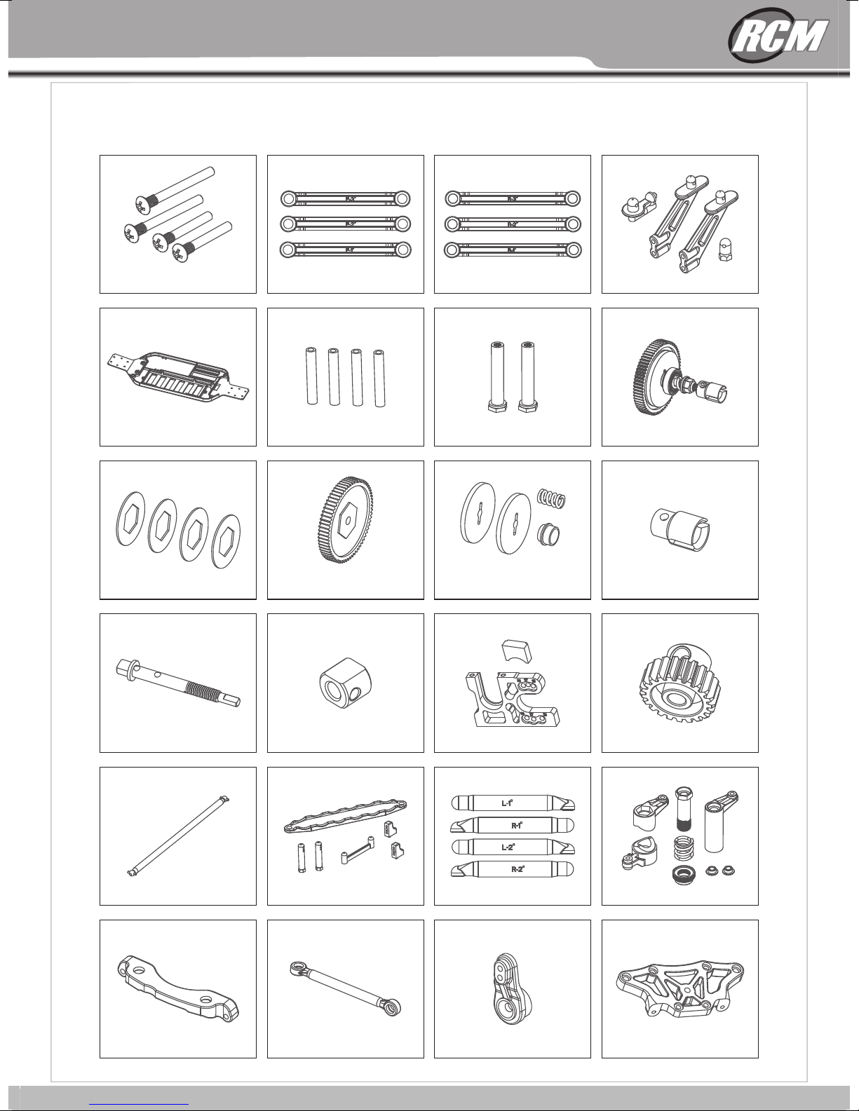
REPLACEMENT PARTS
31
B-10E
REPLACEMENT PARTS
71717170
Complet e Differen tial Set
7174 7175 7176 7177
Diffe renti al Outd rives
front+r ear
7178 71817180
Front Bum per
Diffe renti al Crow n Gear
38T+Sea ling
Diff Pi nion Ge ar 13T (2 pcs) O utdri ve Gear B ox fron t Gea r Box (1p cs)
7179
Front Sho ck Towe r
Diffe renti al Case a nd Sealin g
Front Sus pensi on Arm Set
71737172
Diffe renti al Gear S et (4pcs)
Susp. Arm Hin ge Pin Br ace
front&r ear
71837182 7185
3x30mm Hi nge Pin ( 4pcs)
Steerin g Knuck les
Rear Shoc k Tower
C-Hubs wi th Inse rts
71917190
7184
Rear Susp ensio n Arm Set
7192
Wheel Hex N uts
Univers al Dri
7189718871877186
Rear Hub Ca r.+ Hex
Wheel-A d.(ea ch with 2 pcs)
7193
ve shaft
Rear Hub Ca rrier Ax le
Horizon tal dri ve shaf ts
28
30
Front Swa y Bar Set Rear S way Bar Set
REPLACEMENT PARTS
7197719671957194
Front /Re ar Lowe r
Suspens ion Pin s
Chassis
Asbesto s paper f ricti on plat e
o
Front Upp er rod se t 1 / 2 / 3
o o
Alumini um stru t (4pcs )
Reducti on Gear
Rear Uppe r rod set 1 /2 /3
o o o
Servo Sav er Post
Adjusti ng spri ng/
Adjusti ng spri ng moun t/
Asbesto s briqu ettin g
Wing Moun t Plast ics
7201720071997198
Slipper C lutch c omple te
with Main G ear
7205720472037202
Dogbone -Outd rive
Slipper C lutch
7209720872077206
Reducti on gear s haft Gear Con necti ng cups
Alumini um Cent er Driv eshaft
ng Connec ting Pl ate Steeri ng Servo Tur nbuck le
Steeri
Battery Tr ay and Po sts Steerin g Rods Se rvo Sav er/St eering Arm s
Alumini um Moto r Mount
721272117210
7216
Servo Arm Pla stic
29
31
21T Mot or Gear
7213
721772157214
Front Upp er Chas sis Bra ce

7249
726672657264
7260 7261 7262 7 263
7259725872577256
7251
7253 7 254 72 55
7248 7250
7247
7252
72467244 7245
7267
REPLACEMENT PARTS
M2x10 Soc ket Cap S crew
M3X8 Flat H ead Sel f-
tapping S crew Se t
M3X10 Fla t Head Se lf-
tapping S crew Se t
M3X12 Fla t Head
Self-tapping S crew Se t
M3X20 Fla t Head
Self-ta pping S crew Se t
M3X8 Flat H ead Scr ew Set
M3X6 Pan Se lf-ta pping
Screw Set
M3X10 Pan S elf-t appin g
Screw Set
M3X12 Pan S elf-t appin g
Screw Set
M3X14 Pan S elf-t appin g
Screw Set
M3X16 Pan S elf-t appin g
Screw Set
M3X20 Pan S elf-t appin g
Sc
rew Set
M3X8 Pan He ad Scre w Set M3X10 Pa n Head Sc rew Set Set Screw M 3x3 Set Screw M 3x10
Set Screw M 4x4
Lock Nut M2 .5
Lock Nut M4
M3x4.1 Sc rew rod
M3x4.8 Sc rew rod
Steering Ball Screws φ4.7-M3
φ2x9.7 Pin Set φ 2x10 Pi n Set
33
B-10E
REPLACEMENT PARTS
Middle Up per Cha ssis Pl ate
Rear Shoc k Sprin g(bla ck)
Front Sho ck Set Rear Shoc k Set
Front Sho ck Rods Rear Shoc k Rods
7221722072197218
Front Sho ck Spri ng(bl ack)
7225722472237222
Shock cap
7229722872277226
Shock sea l cover
Shock End S et Uppe r/Low er
Front Tire R im Set Fr ont Tire R im Set
7238
Shock adj ustme ntrin g Shoc k absor ber pisto n group Shock Sea ling Se t (4pcs )
Shock spr ing low er seat
Front/Rear sho ck abso rber
cylinde r block
Tyre+Ins erts fr ont (2p cs) Tyre+Ins erts re ar (2pc s)
Φ8xΦ5x2.5 x4
7233723272317230
Server cr ankse t
723772357234 7236
728272817280
8 8 15 2 9 4 5 5 5 4
Asbesto s paper f ricti on
Antenn
a tube/an tenna c ap
plate φ25 .5x17 .5x1. 0
Φ10xΦ5x4 x10
Φ15xΦ10x4 x7
Complet e Beari ng Set
30
32
4 5 7 4 13 4 6 2 4
Complet e Screw S et

REPLACEMENT PARTS
72467244 7245
M2x10 Soc ket Cap S crew
7248 7250
M3X20 Fla t Head
Self-ta pping S crew Se t
7252
M3X8 Flat H ead Sel ftapping S crew Se t
7249
M3X8 Flat H ead Scr ew Set
7253 7 254 72 55
M3X10 Fla t Head Se lftapping S crew Se t
M3X6 Pan Se lf-ta pping
Screw Set
7247
M3X12 Fla t Head
Self-ta pping S crew Se t
7251
M3X10 Pan S elf-t appin g
Screw Set
M3X12 Pan S elf-t appin g
Screw Set
M3X8 Pan He ad Scre w Set M3X10 Pa n Head Sc rew Set Set Screw M 3x3 Set Screw M 3x10
7260 7261 7262 7 263
Set Screw M 4x4
M3X14 Pan S elf-t appin g
Screw Set
Lock Nut M2 .5
M3X16 Pan S elf-t appin g
Screw Set
Lock Nut M4
726672657264
M3X20 Pan S elf-t appin g
Screw Set
7259725872577256
M3x4.1 Sc rew rod
7267
3x4.8 Scr ew rod
M
Steering Ball Screws φ4.7-M3
33
φ2x9.7 Pin Set φ 2x10 Pi n Set
31

7284 72 86
7288 7 289
7283 7285
7287
REPLACEMENT PARTS
Brushed E SC Ni-MH 300 0mAh 7. 2V 15C Brus hed Motor 540 3.5 KG Serv o
Brushle ss ESC 60 A Li-Po 320 0mAh 7. 4V 18C Brushle ss Moto r Kv360 0
35
/
/
B-10E
REPLACEMENT PARTS
7271727072697268
φ2x11 Pin S et
E butto n φ2.5x0. 4
φ10xφ5.5x0.3 Washers φ8xφ3.2x0.5 Washers
7239/72 40/7241
Ball bear ing φ8x 5x2.5 Ball beari ng φ10x 5x4 B all bea ring φ1 5x10x 4
7275727472737272
Ball Head S et R-Pin Set
7279727872777276
Rear Whee l Shaft Wash ers
7243
φ8xφ5.1x0.3 Washers
Diffe renti al seal ring
Body (whi te)72 39
Body(ye llow) 7240
Body tran spare nt 7241
7242
Body and ta il stic ker
32
Tail Wing(W hite/ y ellow / black )
7290
Dust cove r
34

REPLACEMENT PARTS
R E P L A C E ME N T P A R T S
7 2 8 3 7 2 8 5
7283 7285
Brushed E SC Ni-MH 300 0mAh 7. 2V 15C Brus hed Motor 540 Servo 6-15kgs
Brushed E SC Ni-MH 300 0mAh 7. 2V 15C Brus hed Motor 540 3.5 KG Serv o
7 2 8 7
7287
Brushless ESC 45A-120A
Brushle ss ESC 60 A Li-Po 320 0mAh 7. 4V 18C Brushle ss Moto r Kv360 0
7 2 8 4 7 2 8 6
7284 72 86
7 2 8 8 7289
7288 7 289
LiPo 3600-6000mAh -
7.4v-11.1v
Motor Brushless 4 Poles
3000-3900kv
35
33

Por medio de la presente RC MITICO S.L. declara que el equipo de radiocontrol cumple los
requisitos esenciales y cualesquiera otras disposiciones aplicables o exigibles de la Directiva
1999/5/CE.
Hereby, RC MITICO S.L. declares that this Radio Control Equipment is in compliance with the
essential requirements and other relevant provisions of Directive 1995/5/EC.
IMPORTADOR:
CIF.: B-86452125
28914, Leganés - Madrid (España)
+14
 Loading...