

Page 1

USER MANUAL
MANUALE D’USO
VSA 2050 II
VSA 1250 II
VSA 850 II
- DIGITALLY STEERABLE ARRAY
SPEAKER SYSTEMS
- DIFFUSORI ATTIVI DIGITALI
DI TIPO “ARRAY”
Page 2
4
ENGLISH
IMPORTANT
WARNING
SAFETY PRECAUTIONS
IMPORTANT
Before connecting and using this product, please read this instruction manual carefully and
keep it on hand for future reference.
The manual is to be considered an integral part of this product and must accompany it
when it changes ownership as a reference for correct installation and use as well as for the
safety precautions.
RCF S.p.A. will not assume any responsibility for the incorrect installation and / or use of
this product.
WARNING: To prevent the risk of fire or electric shock, never expose this product to rain
or humidity.
This device is intended for indoor use only.
SAFETY PRECAUTIONS
1. All the precautions, in particular the safety ones, must be read with special attention, as
they provide important information.
2.1 - PRIMARY POWER SUPPLY FROM MAINS
- The mains voltage is sufficiently high to involve a risk of electrocution: never install or
connect this product when its power cord is plugged in.
- Before powering up, make sure that all the connections have been made correctly and
the voltage of your mains corresponds to the voltage shown on the rating plate on the
unit, if not, please contact your RCF dealer.
- The metallic parts of the unit are earthed by means of the power cord.
An apparatus with CLASS I construction shall be connected to a mains socket outlet
with a protective earthing connection.
- Protect the power cord from damage. Make sure it is positioned in a way that it
cannot be stepped on or crushed by objects.
- To prevent the risk of electric shock, never open this product: there are no parts inside
that the user needs to access.
2.2 - 24 V dc SECONDARY POWER SUPPLY BY BATTERIES
- The apparatus operating voltage is 24 V dc, therefore it is necessary to connect in
series several batteries having a lower nominal voltage, example: 2 x 12 V.
- Always use rechargeable batteries, which need to be chosen according to the
maximum possible load.
- Verify the polarity of batteries is correct.
- Do NOT short-circuit batteries (i.e. connecting the 2 opposite poles together with
metallic wires).
- Throw empty batteries away according to your country laws about ecology and
environment protection.
3. Make sure that no objects or liquids can get into this product, as this may cause a short
circuit.
This apparatus shall not be exposed to dripping or splashing. No objects filled with liquid
(such as vases) and no naked sources (such as lit candles) should be placed on this
apparatus.
4. Never attempt to carry out any operations, modifications or repairs that are not expressly
described in this manual.
Contact your authorized service centre or qualified personnel should any of the following
occur:
- The product does not function (or functions in an anomalous way).
- The power cord has been damaged.
- Objects or liquids are inside the product.
- The product has been subject to a heavy impact.
Page 3

5
ENGLISH
5. If this product is not used for a long period, disconnect its power cord and / or batteries.
6. If this product begins emitting any strange smell or smoke, switch it off
immediately and disconnect its power cord.
7. Do not connect this product to any equipment or accessories not foreseen.
For suspended installation, only use the dedicated anchoring points and do not try to hang
this product by using elements that are unsuitable or not specific for this purpose.
Also check the suitability of the support surface to which the product is anchored (wall,
ceiling, structure, etc.), and the components used for attachment (screw anchors, screws,
brackets not supplied by RCF etc.), which must guarantee the security of the system /
installation over time, also considering, for example, the mechanical vibrations normally
generated by transducers.
To prevent the risk of falling equipment, do not stack multiple units of this product unless
this possibility is specified in the user manual.
8. RCF S.p.A. strongly recommends this product is only installed by professional
qualified installers (or specialised firms) who can ensure correct installation
and certify it according to the regulations in force.
The entire audio system must comply with the current standards and
regulations regarding electrical systems.
9. Supports and trolleys
The equipment should be only used on trolleys or supports, where necessary, that are
recommended by the manufacturer. The equipment / support / trolley assembly must be
moved with extreme caution.
Sudden stops, excessive pushing force and uneven floors may cause the assembly to
overturn.
10. Mechanical and electrical factors need to be considered when installing a professional
audio system (in addition to those which are strictly acoustic, such as sound pressure,
angles of coverage, frequency response, etc.).
11. Hearing loss
Exposure to high sound levels can cause permanent hearing loss. The acoustic pressure
level that leads to hearing loss is different from person to person and depends on the
duration of exposure. To prevent potentially dangerous exposure to high levels of acoustic
pressure, anyone who is exposed to these levels should use adequate protection devices.
When a transducer capable of producing high sound levels is being used, it is therefore
necessary to wear ear plugs or protective earphones.
See the manual technical specifications to know the maximum sound pressure level.
12. Situate this product far from any heat sources and always ensure adequate air
circulation around it.
13. Do not overload this product for a long time.
14. Never force the control elements (keys, knobs, etc. ).
15. Do not use solvents, alcohol, benzene or other volatile substances for cleaning the
external parts of this product.
Use a dry cloth.
NOTES ABOUT AUDIO SIGNAL CABLES
To prevent the occurrence of noise on microphone / line signal cables, use screened cables
only and avoid putting them close to:
- Equipment that produces high-intensity electromagnetic fields.
- Mains cables.
- Loudspeaker lines.
Page 4
6
ENGLISH
RCF S.P.A. THANKS YOU FOR PURCHASING THIS PRODUCT, WHICH HAS BEEN
DESIGNED TO GUARANTEE RELIABILITY AND HIGH PERFORMANCES.
DESCRIPTION
VSA
II series is made of multi-amplified vertical steerable arrays that represent one of the
latest RCF applications in terms of digital audio technology.
The 3 available models have similar features, but:
- VSA
2050 II is the top model and includes 20 amplifiers and 20 full-range 3.5”
RCF transducers, its vertical dispersion is controlled up to 10° from 150 Hz and up.
- VSA 1250
II includes 12 amplifiers and 12 full-range 3.5” RCF transducers, its
vertical dispersion is controlled up to 10° from 300 Hz and up.
- VSA 850 II includes 8 amplifiers and 8 full-range 3.5” RCF transducers, its
vertical
dispersion is controlled up to 10° from 500 Hz and up.
The internal digital signal pr
ocessor processes the audio signal sent to each single internal
transducer in order to control the overall vertical acoustic dispersion.
VSA II series
speakers are the ideal for indoor installations, where a critical acoustic
environment can be an issue and a moderate visual impact is required, for instance:
houses of worship, airports, railway stations, auditoriums, congress halls, sport halls,
shopping malls, etc. .
Unlike traditional sound columns, VSA speaker calibration is carried out electronically via
either RdNet software or its VSA SMART RC remote control for smartphones (to be purchased
separately and necessary, as it also includes the USB / RS 485 cable adapter with RJ45 connector
for linking to a computer), by specifying the installation height above the floor and the listening
area (or the maximum distance from speakers to audience).
The signal is fully processed and amplified in the digital domain, thanks also to 6 FPGAs (‘Field
Programmable Gate Array’) that manage all the data inside the speaker system.
The circuitry is modular to get maximum reliability and easy servicing.
VSA II s
peakers include 2 independent power supply units, controlled by a microprocessor
for either AC (230 / 115 V) or DC (24 V) operation, to get full back-up facility when the
product is intended for emergency purposes.
Each internal circuit is monitored (voltage, current and temperature).
VSA II series speakers meet all re
quirements needed by sound systems for emergency purposes.
One of the most important feature of the VSA digital arrays is their simple configuration, thanks
to RdNet software or its VSA SMART RC remote control for smartphones.
In a few steps, it is possible to tilt down and shape the acoustic beam in a virtual way, while the
column speaker is installed in a physical vertical position.
This configurability permits to address the audio signal exactly to the listening area, avoiding to
send acoustic energy to ceilings and empty floors, thus not introducing additional bad reflections
that would affect speech intelligibility, mainly in critical environments with high reverberation
time.
20
‘class D’ amplifiers (50 W each, with high capacity power supply) for the VSA 2050 II model,
12 for VSA 1250 II and 8 for VSA 850 II, assure the best possible control and dynamics.
Each cabinet has four LEDs (AC, DC, FAULT and PRIORITY) and provides dry contacts (of an
internal relay) for remote ‘fault’ indication.
Thanks to a sophisticated algorithm developed by RCF, the focus control is not strictly necessary
as the best possible result is guaranteed overall the covered listening areas.
It is possible to set the acoustical coverage (tilt and beam) according to installation height and
the listening area to be served.
Page 5
7
ENGLISH
Each speaker has 2 audio inputs, of which one has priority.
VS
A II speakers can be installed very close to the wall (to be unobtrusive) thanks to their
compact sizes, slim shapes and their (included) wall mounting accessories.
SWM-BR VSA II optional accessory: each kit includes a pair of swivel brackets for a single
VSA II speaker wall mounting, allowing a horizontal angle pointing up to 60°.
Connections are separated: AC and DC power supply at one end, audio signals and interfaces
on the other. The electrical connections are clearly labelled and made through screw terminals
and other suitable and easy-to-wire connectors.
VSA II series (standard version) is intended for indoor sound systems
only.
INSTALLATION
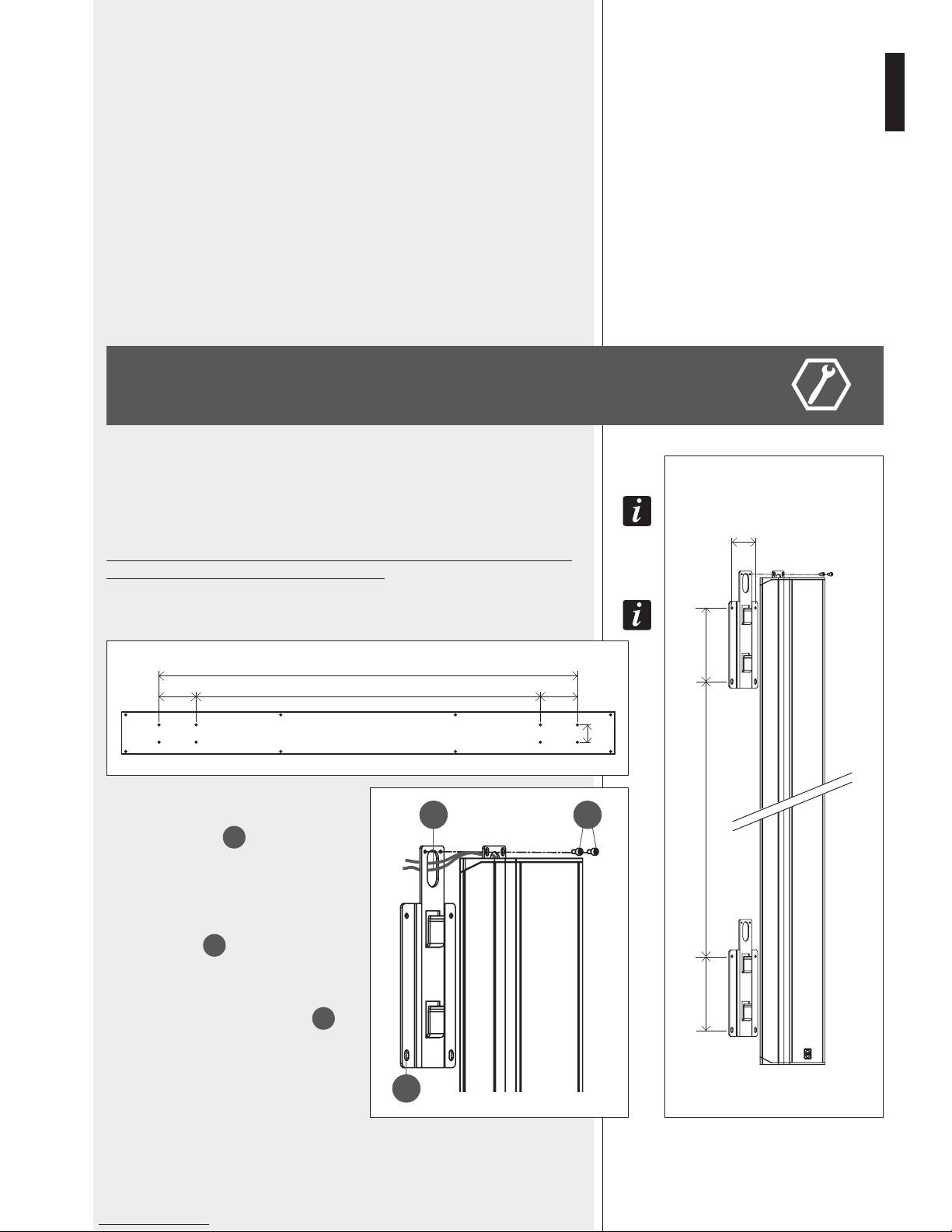
The speaker shall be wall-mounted through the two included brackets (picture 1).
To swivel iT
wiTh a horizonTal angle up To 60°, iT is necessary To purchase The opTional
SWM-BR VSA II accessory kiT.
Minimum installation height: the speaker bottom shall be at least 1 m from
the floor (suggested height: from 1.5 to 3 m).
The wood package lid can also be used as drilling TemplaTe (picTure 2)!
Each bracket shall be fixed to the wall by 4
dowels for 5 mm screws (passing through the 4
holes, see picture 3 –
A
).
If put to recessed pipelines, the power cables
(230-115 V ac and, separately, 24 V dc) can
pass through the bracket and the loudspeaker
holes (picture 3 –
B
).
Put the speaker on the bracket hooks and fix
it with the security screws (picture 3 –
C
),
which prevent the speaker might accidentally
slip off and fall.
A
B
C
PICTURE 3 PICTURE 1
PICTURE 2
1910 (VSA 2050 II), 1202 (VSA 1250 II), 848 (VSA 850 II
)
170 170
80
80
170170 1570 (VSA 2050), 862 (VSA 1250), 508 (VSA 850)
1570 (VSA 2050 II), 862 (VSA 1250 II), 508 (VSA 850 II)
[mm]
[mm]
Page 6
8
ENGLISH
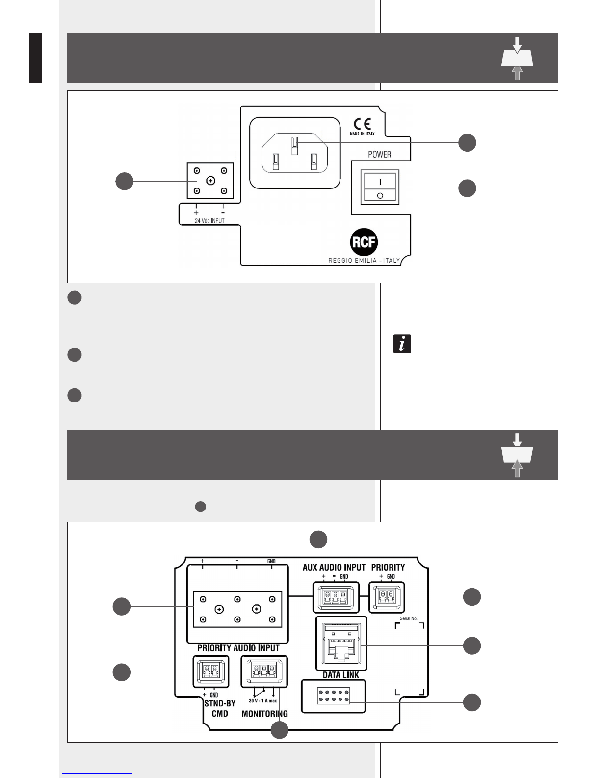
1
POWER
Main power switch.
I : ON O : OFF
afTer Turning The speaker on, The sysTem Takes abouT 15 seconds (‘sTarT-up’) To geT fully operaTing.
2
Socket for the power cord.
Before powering up, make sure the mains voltage corresponds to the voltage
indicated on the unit label.
3
24 Vdc INPUT
Secondary power supply input (24 V dc).
TOP PANEL (power supply)
BOTTOM PANEL (signals and commands)
4
7
6
9
10
5
8
1
2
3
Remove the bottom panel cover with the 4 LEDs to access to connections (by disconnecting its cable from the respective port 10).
Page 7

9
ENGLISH
4
PRIORITY AUDIO INPUT
Main audio input that can be enabled by the remote control or the PRIORITY
6
command.
The ceramic terminal allows its use in sound systems for emergency purposes.
+ (hot) signal, – (cold) signal, GND ground
5
AUX AUDIO INPUT
Auxiliary audio input (with removable plug) that can be enabled by the remote control.
+ (hot) signal, – (cold) signal, GND ground
only an audio inpuT can be open aT a Time. iT is noT possible To mix 2 inpuT signals.
6
PRIORITY
Priority command input, activated when the + and GND pins are short-circuited.
The priority function is mainly for emergency: when activated, the PRIORITY AUDIO
INPUT
4
gets open (the aux input gets muted) regardless the remote control
settings, the speaker is forced on if the stand-by command 7 is present, the
volume is set to its maximum level.
7
STND-BY CMD
Stand-by command input, activated when the + and GND pins are short-circuited.
It has no effect if the PRIORITY
6
command is present.
The speaker has also an auTomaTic sTand-by mode afTer ca. 30 minuTes wiThouT deTecTing any
audio signal. when in auTomaTic sTand-by mode, The speaker will auTomaTically Turn on as soon
as an audio signal is deTecTed on The selecTed inpuT.
8
MONITORING
Dry contacts (normally-closed, common, normally-open) of an internal relay that can
be used for ‘faulty’ remote indication.
This relay is activated when the speaker is working properly.
During any fault (or the speaker is switched off), the relay is deactivated.
Max. current applicable on contacts: 1 A. Max. voltage applicable on contacts: 30 V.
9
DATA LINK
RJ 45 port to link to a computer USB port for configuration via RdNet software (the
cable is included in the VSA SMART RC kit).
The standard is RS 485:
10
Port to connect the bottom panel cover with the 4 LEDs.
1. Orange/White
2. Orange
3. Green/White
4. Blue
5. Blue/White
6. Green
7. Brown/White
8. Brown
—
—
— A
— B
PINS
] GROUND
-1
-2
-3
-4
-5
-6
-7
-8
Page 8

10
ENGLISH
LEDS ON THE BOTTOM PANEL COVER
during The speaker sTarT-up (afTer swiTching on, ca. 15 seconds) all The 4 leds are flashing.
From left to right:
1 AC (green)
When lit: AC power supply (mains: 230 / 115 V) is present and the speaker is operating.
2 DC (green)
When lit: 24 V DC power supply is present and the speaker is operating.
If batteries are not connected (or not available) or the voltage is lower than the minimum
threshold, this LED will be off.
if boTh AC and DC leds (only) are flashing, The speaker is in sTand-by mode.
3 FAULT (yellow)
When lit: a fault has been detected.
4 PRIORITY (red)
When lit: the priority function (of the PRIORITY AUDIO INPUT 4) is activated by the
respective contact 6 .
LEDS ON THE BOTTOM PANEL
COVER
NOTES ABOUT THE RDNET SOFTWARE
RDNET SOFTWARE INSTALLATION
The RDNET software is protected by international copyright laws and is to be used to
configure the RCF RDNET system devices only.
It is not allowed to modify or change or try to decompile this software.
In no event shall RCF S.p.A. be liable to end-users for any damage whatsoever, including
but not limited to financial damages for loss of business profits or business information
due to the software use or inability to use this product.
The foregoing provision is effective even if RCF S.p.A. has been advised of the possibility
of such damages.
Even if the SOFTWARE has any material, verifiable and reproducible program errors, RCF
S.p.A. shall have no obligation to modify such errors.
MiniMuM RequiReMent: a PC with either MiCrosoft ‘windows® Vista’ or ‘7’
(or later) oPerating systeM, haVing an aVailable Usb Port.
Before installing a new software release, it is necessary to remove the previous
version (if installed). Verify also that the new release is the right one for the PC
operating system: either 32-bit or 64-bit.
Run rcf_rdnetsetup_(versione).exe to start the setup wizard.
Click NEXT > to proceed.
Page 9

11
ENGLISH
Read the license agreement.
Click ‘I Agree’ to accept and proceed with the
software installation.
It is now possible to change the installation
folder (directory) of the RDNET software (or keep
the default path).
Click INSTALL to proceed.
As soon as the installation ends, it will be necessary to
reboot your computer.
Choose either ‘Reboot Now’ to reboot immediately or ‘I
want to reboot later’ to reboot later manually.
Click FINISH to quit.
Page 10

12
ENGLISH
Link the computer USB port to the VSA speaker DATA LINK
9
input by using the cable included in the VSA SMART RC kit.
Run the RDNET software (in Windows, click):
Start > Programs > RCF > RDNet > RDNet
(or double-click RDNet icon on the desktop).
First, in the main menu, click ‘Go’ and then ‘Controllers’.
In the ‘Controllers’ section (bottom left in the main window), click ‘Match All’ (or click
each single ‘Match’ button or simply drag and drop) to add all linked USB devices (COM)
to the ‘Workspace Controllers’ list (bottom right in the main window).
CONFIGURATION BY RDNET SOFTWARE
Page 11

13
ENGLISH
In the main menu, now click ‘Quickstart’: in the bottom right-hand corner of the main
window (in the bottom bar) the word ‘OFFLINE’ becomes ‘ONLINE’.
The detected VSA speaker module now appears (e.g. VSA 2050).
The ‘√’ symbol (on green background) indicates that the VSA speaker has been properly
connected (while the ‘–’ symbol on red background indicates ‘not detected’ / ‘not present’).
To open and edit the VSA setup window, point the PC mouse on
the VSA module and double-click
(or right-click and select ‘Show Obj Details’)
To upgrade the VSA speaker firmware
(main menu: “Advanced > Firmware Upgrade...”).
Refer to the RDNET user manual for all software functions.
MUTE
Click MUTE to mute the VSA speaker (all MUTE buttons get red). Click MUTE again to
unmute.
SOLO
This function is useful only when an RdNet network with several speakers is present
(through either a RDNET CONTROL 8 or CONTROL 2 device). Read the RdNet software
user manual.
Click SOLO to make the selected VSA speaker the only one activated, while the others are
muted.
STANDBY
Stand-by mode.
M1 to M20 buttons (on the left).
VSA test mode that allows to listen to each single transducer.
Click one of the M1 – M20 buttons (relative to each single transducer) for solo listening.
Click either it again to reset the normal operation or another one to keep testing.
Green: unmuted, red: muted.
EQ: click EQ to open and edit the equalizer window (relative to the three custom
equalizations), which includes both Gain and Delay settings as well.
BEAM: click BEAM to open and edit the beam setting window.
SETUP WINDOW
Page 12

14
ENGLISH
INPUT CHANNEL
Input channel selection:
- PRIORITY PRIORITY AUDIO INPUT is open
(AUX AUDIO INPUT is muted).
- AUXILIARY AUX AUDIO INPUT is open
(PRIORITY AUDIO INPUT is muted).
the aUXiliary seleCtion has no effeCt when the Priority fUnCtion of the Priority aUdio inPUt
is aCtiVated.
AUTO STAND-BY
If set to 25 Min, VSA speakers will automatically turn off (stand-by) after 25 minutes
without detecting any audio signal and turn on as soon as an audio signal is detected on
the selected input (or due to the activation of the priority function).
Set AUTO STAND-BY to OFF to disable this function.
ACTIVE EQUALIZER
The equalization can be chosen among 6 different settings: 3 are presets and 3 are editable
by the user (custom 1, 2, 3).
- FLAT no equalization (flat frequency response)
- SPEECH equalization optimized for speech
- MUSIC equalization optimized for music
- CUSTOM 1 – 2 – 3 3 custom equalizations by setting max. 8 filters
BEAM SETTING WINDOW
Click BEAM to open and edit the beam setting window.
Page 13

15
ENGLISH
Values represented graphically:
- H: speaker bottom installation height
- Ha: considered listening area height (1.2 m)
- In EASY BEAM mode, the minimum D1 and maximum D2 distances of the listing area
from the speaker
- In EASY FOCUS mode, the maximum distance F to be covered
- In FREE BEAM mode, the tilt T (vertical angle downwards) and the beam B (vertical
dispersion).
2. Set the speaker installation height (considering the distance from its bottom to the
floor) by clicking COLUMN HEIGHT.
The range is from 1 to 6 metres (0.1 m steps) in the EASY BEAM mode, from 1.5 to 3
metres (0.5 m steps) in the EASY FOCUS mode, from 2 to 6 metres (0.1 m steps) in the
FREE BEAM mode.
3a. (EASY BEAM) Set the listening area D through AUDIO RANGE.
Both minimum D1 and maximum D2 distances (from speaker) can be selected among
several presets according to the speaker height H.
3b. (EASY FOCUS) Set the maximum distance to be covered through FOCUS.
3c. (FREE BEAM) Set the TILT and then the BEAM.
1. First, select the SETTINGS MODE:
- EASY BEAM allows to specify the listening area to be covered by selecting a preset
audio range.
- EASY FOCUS, simple, easy and suitable for all systems, advisable for users and
installers that are not so expert. Only two values are necessary: the speaker installation
height and the maximum distance to be covered.
- FREE BEAM, for expert users / installers, it allows the (virtual) setting of both speaker
tilt and beam.
Page 14

16
ENGLISH
EQUALIZER SETTING WINDOW
Click EQ to open and edit the equalizer window (relative to the three custom equalizations),
which includes both Gain and Delay settings as well.
First, in the Active Equalizer option menu, choose one of the three custom equalizations
CUSTOM 1 – 2 – 3 to edit.
It is possible to set up to eight independent filters (Filter 1, 2, 3, 4, 5, 6, 7, 8).
Enabled: click the checkbox to toggle each filter.
Move the mouse on its white background (making it green) to highlight a filter (if present) on
the EQ graph.
Type:
- DISABLED: the filter is disabled (by-pass).
- PEQ: parametric equalizer that allows to adjust the level at the settable centre frequency and
specify the Q factor (the adjusted level can be widened or narrowed).
- SHELVING HIGH: increase or decrease the level of all frequencies above the selected
frequency by the specified amount.
- SHELVING LOW: increase or decrease the level of all frequencies below the selected frequency
by the specified amount.
- The BUTTERWORTH, LINKWITZ-RILEY, BESSEL options are only available for the filters
no.1 (‘high-pass’) and no.8 (‘low-pass’).
Slope: filter slope setting (dB / oct).
Q: Q factor setting.
Gain (dB): filter gain setting.
Freq (Hz): either filter frequency selection or PEQ central frequency setting.
Page 15

17
ENGLISH
File Commands:
- SAVE: it saves to PC the current equalization as .rde file.
- LOAD: it loads from PC an equalization previously saved as .rde file.
Eq. options:
- FLATTEN: it disables all filters (flat frequency response).
- BYPASS EQ.: it disables the equalization, but without changing filter settings.
- PHASE PLOT: if selected, the phase plot is shown (green line).
Devices commands:
- STORE: it sends and stores the equalization to the VSA speaker.
- SEND: it sends (without storing) the equalization to the VSA speaker.
For each filter, frequency and gain can be adjusted either graphically (through the mouse) by
dragging the little coloured square or in an analytical way (by inserting values in cells or rotating
controls).
The overall equalization is shown as a red line, the intervention of the selected filter as a green
line, the intervention of a filter that is not selected as a white line.
For example, to apply a 12 dB attenuation for frequencies below 80 Hz: enable the filter 1 by
clicking its ‘Enabled’ checkbox, select the SHELVING LOW filter type, set the gain to –12 dB and
frequency to 80 Hz .
Page 16

18
ENGLISH
To add a second filter (i.e. PEQ): enable the filter 2, select the PEQ filter type, its gain and
central frequency, then set its Q factor.
INV. PHASE
If selected (red light), the VSA speaker phase is inverted.
Finally, click either STORE (send and store) or SEND all EQ settings (without storing) to
the VSA speaker.
GAIN
Gain setting (dB) of all the audio range (0 = flat).
DELAY
Delay line setting.
If the sound system is made of two or more speaker lines, it is advisable to delay the sound
from the second line onwards (setting a delay time directly proportional to the distance
from the first speaker line), in order to reduce the perception of echo (due to the different
reception times of sounds coming from speakers that are distant one another), give a
correct sense of depth to listeners and improve the speech intelligibility.
You can set the distance in meters (graphically or analytically) or the time in milliseconds
(by entering the numeric value only).
eXaMPle (see the figUre):
-
the b sPeaker is 15 Metres far froM the a sPeaker (first line) and needs to be delayed by
setting the delay ParaMeter to
15 m.
-
the C sPeaker is 30 Metres far froM the a sPeaker (first line) and needs to be delayed by setting
the delay ParaMeter to
30 m.
Page 17

19
ENGLISH
SPECIFICATIONS
VSA 2050 II VSA 1250 II VSA 850
II
ACOUSTICAL SPECS.
Frequency response 100 Hz ÷ 18 kHz 120 Hz ÷ 18 kHz 130 Hz ÷ 18 kHz
Max. sound pressure level
(A-weighted at 30 m)
96 dB 94 dB 93 dB
Horizontal coverage angle 130° 130° 130°
Vertical coverage angle selectable from 10° to 30° selectable from 10° to 30° selectable from 10° to 30°
Vertical steering angle selectable from 0° to –40° selectable from 0° to –40° selectable from 0° to –40°
Transducers
20 x 3.5”
full-range loudspeakers
12 x 3.5”
full-range loudspeakers
8 x 3.5”
full-range loudspeakers
INPUT SECTION
Input sensitivity 0 dBu
Connectors
balanced screw terminals
balanced ceramic screw terminal
Controls
remote control infrared port
priority command
remote ‘fault’ indication
stand-by remote command
LEDs Power supply, fault, priority
PROCESSOR
Type
Texas TMS320C6726
32-bit floating point DSP
Spartan3A FPGA
24 bit AD converters, 48 kHz
Operation
20 PEQ channels, compression, beam forming,
20 limiters and protections
AMPLIFIERS
Type 20 ‘class D’ amplifiers 12 ‘class D’ amplifiers 8 ‘class D’ amplifiers
Power (each amplifier) 50 W 50 W 50 W
POWER SUPPLY
AC power supply
either 230 V or 115 V (according to the model),
50 – 60 Hz, type: ‘switching’
Consumption
stand-by 26 W 21 W 18 W
operating,
no signal
66 W 46 W 36 W
max. power 600 W 600 W 400 W
Internal fuse (AC) T3.15AL/250 V (230 V); T6.3AL/250 V (115V)
Secondary DC power supply 24 V
DC power in connector ceramic screw terminal
PHYSICAL SPECS.
Cabinet material aluminium (powder coated)
Dimensions (w, h, d) 125, 2070, 97 mm 125, 1340, 97 mm 125, 980, 97 mm
Net weight 19 kg 14 kg 10 kg
Colour
RAL 900
3 (white)
INCLUDED ACCESSORIES
Installation 2 wall-mounting brackets
REQUIRED ACCESSORY TO BE PURCHASED SEPARATELY
Remote control for smartphone with the
USB / RS 485 cable to link to PC
VSA SMART RC
OPTIONAL ACCESSORY
Installation with a
horizontal angle up to 60°
SWM-BR
VSA II
Page 18

10307633 revA
2018 / 03
www.rcf.it
RCF S.p.A. Italy
Via Raffaello Sanzio, 13
42124 Reggio Emilia - Italy
Tel +39 0522 274 411
Fax +39 0522 232 428
e-mail: info@rcf.it
Salvo eventuali errori ed omissioni.
RCF S.p.A. si riserva il diritto di apportare modiche senza preavviso.
Except possible errors and omissions.
RCF S.p.A. reserves the right to make modifications without prior notice.
 Loading...