

Page 1

UP 4061 • UP 4121 • UP 4161
UNITÀ DI POTENZA
POWER AMPLIFIERS
UNITES DE PUISSANCE
LEISTUNGSEINHEIT
UNIDAD DE POTENCIA
MANUALE D’INSTALLAZIONE E D’USO
INSTALLATION AND OPERATION MANUAL
INSTRUCTIONS D’INSTALLATION ET D’EMPLOI
INSTALLATIONS UND BEDIENUNGSANLEITUNG
MANUAL DE USO Y DE INSTALACION
RCF S.p.A.
Page 2
IMPORTANTE
Prima di collegare e utilizzare l’apparecchio
leggete attentamente le istruzioni contenute in
questo manuale, che vi consigliamo di conservare per
riferimenti futuri.
Il presente manuale costituisce parte integrante
del prodotto, e deve accompagnare quest'ultimo
anche nei passaggi di proprietà, per permettere al
nuovo proprietario di conoscere le modalità
d'installazione e d'utilizzo e le avvertenze per la
sicurezza.
L'installazione errata dell’apparecchio esime la
RCF S.p.A da ogni responsabilità
WARNING : Per prevenire i rischi di
amme o scosse elettriche, non esponete
l’apparecchio alla pioggia o all'umidità.
Avvertenze per la sicurezza
1. Tutte le avvertenze accompagnate con il simbolo
devono essere lette con particolare
attenzione, in quanto contengono importanti
informazioni per la sicurezza.
2. La tensione di alimentazione dell’apparecchio ha
un valore sucientemente alto da costituire un
rischio di folgorazione per le persone: non
procedete mai all’installazione o connessione
dell’apparecchio con l’alimentazione inserita.
3. Prima di alimentare l’apparecchio assicuratevi
che la tensione della vostra rete di alimentazione
corrisponda con la tensione impostata dal
selettore di tensione (rif. 24 - g. 1-pag. 42), in
caso contrario rivolgetevi al vostro rivenditore
RCF S.p.A, che provvederà a
congurare l’apparecchio per la tensione corretta.
4. Le parti metalliche dell’apparecchio risultano
collegate a terra tramite il cavo di alimentazione.
Se la presa di corrente utilizzata per
l’alimentazione non fornisce il collegamento con
la terra, contattate un elettricista qualicato , che
provvederà a connettere a terra l’apparecchio
tramite il morsetto (13) (g. 1 - pag. 42).
5. Accertatevi che il cavo di alimentazione
dell’apparecchio non possa venire calpestato o
schiacciato da oggetti, al ne di salvaguardarne
la perfetta integrità.
6. Per evitare il rischio di shock elettrici, non aprite
mai l’apparecchio: all’interno non vi sono parti
che possono essere utilizzate dall’utente.
7. Impedite che oggetti o liquidi entrino all’interno
dell’apparecchio, in quanto potrebbero causare
un corto circuito.
2
ITALIANO
8. Non tentate riparazioni non descritte in questo
manuale; contattate centri di assistenza
autorizzati o personale altamente qualicato
quando:
A. L’apparecchio non funziona (o funziona in
modo anormale).
B. Il cavo di alimentazione ha subito gravi danni.
C. Oggetti o liquidi sono entrati nell’apparecchio.
D. L’apparecchio ha subito forti urti.
9. Qualora l’apparecchio non venga utilizzato per
lunghi periodi, togliete la tensione dal cavo di
alimentazione.
10. Nel caso che dall’apparecchio provengano odori
anomali o fumo, spegnetelo immediatamente, e
togliete la tensione dal cavo di alimentazione.
11. Per evitare il rischio di shock elettrici non
connettete o disconnettete il cavo di
alimentazione con le mani bagnate; aerrate
sempre direttamente la spina, e non tirate mai il
cavo.
12. Non dirigete il getto di spray sull’apparecchio (es.
insetticidi, prodotti per la pulizia, ecc.): i gas
utilizzati potrebbero incendiarsi
improvvisamente.
Precauzioni per l’utilizzo
Non ostruite le griglie di ventilazione
dell’apparecchio.
Evitate di far lavorare l’unità di potenza in
sovraccarico per lungo tempo.
Serrate a fondo i morsetti per diusori, al ne di
garantire un contatto sicuro.
Non sforzate gli organi di comando (tasti, controlli,
ecc.).
Per la pulizia delle parti esterne evitate l’uso di
diluenti, alcol, benzina, o altre sostanze volatili.
Descrizione
Le unità di potenza della serie “ 4000 ” sono state
espressamente studiate per la diusione di annunci
e/o programmi musicali in tutti gli impianti di
sonorizzazione di tipo PA. Incorporano le seguenti
funzioni:
– 1 ingresso RCA sbilanciato.
– 1 ingresso bilanciato su morsettiera.
– 1 uscita RCA in parallelo con l’ingresso
sbilanciato.
– Possibilità di rendere prioritario l’ingresso
bilanciato sull’ingresso sbilanciato.
– Sensibilità dell’ingresso RCA selezionabile fra i
valori 0 dB e -20 dB.
– Uscite per diusori ad impedenza costante (4 Ω )
ed a tensione costante (25-50-70-100 V).
Page 3

– Modalità “stand-by” che permette di
telecomandare l’accensione dell’apparecchio
(escludibile).
– Uscita ausiliaria per segnalazione “overload”.
– Filtri “ H.P.” (passa-alto) e “ L.P.” (passa-basso).
– Controlli per toni alti e bassi.
– Spie “ STD-BY”, “OVERLOAD”, “SIGNAL”,
“PEAK”.
– Doppia alimentazione in corrente alternata
(115/230 Vac).
– Alimentazione in corrente continua 24 Vdc.
– Manopole frontali rimovibili con tappi di
chiusura.
Comandi e Funzioni
(Fig. 1 - pagina 42)
1) Controllo toni bassi
La manopola esalta (rotazione oraria) o attenua
(rotazione antioraria) le basse frequenze. Con la
manopola nella posizione centrale la risposta in
frequenza non viene alterata. Per evitare che il
livello possa essere modicato, è possibile
rimuovere la manopola, e chiudere il foro del
pannello mediante l’apposito tappo fornito in
dotazione.
2) Controllo toni alti
La manopola esalta (rotazione oraria) o attenua
(rotazione antioraria) le alte frequenze. Con la
manopola nella posizione centrale la risposta in
frequenza non viene alterata. Per evitare che il
livello possa essere modicato, è possibile
rimuovere la manopola, e chiudere il foro del
pannello mediante l’apposito tappo fornito in
dotazione.
3) Controllo di volume generale
La manopola consente di regolare il livello nale
del segnale disponibile sulle uscite per diusori
“POWER OUTPUTS” (rif. 12 e 14). Per evitare che
il volume generale possa essere modicato, è
possibile rimuovere la manopola, e chiudere il
foro del pannello mediante l’apposito tappo
fornito in dotazione.
4) Interruttore “POWER”
Permette l’accensione e lo spegnimento
dell’apparecchio.
5) Spia “STD-BY”
La spia si accende quando l’unità di potenza è in
modalità “stand-by”.
6) Spia “OVERLOAD”
L’accensione della spia indica che l’unità di
potenza sta funzionando in sovraccarico. Questa
condizione è generalmente causata da un
problema sulla linea per diusori.
3
AVVERTENZA : All’accensione dell’unità di
potenza la spia “ OVERLOAD” si illuminerà per
alcuni secondi: questo non é indice di problemi,
ma corrisponde al normale funzionamento
dell’apparecchio, che eettua un test iniziale ogni
volta che l’unità di potenza viene accesa.
7) Spia “SIGNAL”
La spia si accende quando sull’uscita per diusori
“POWER OUTPUTS” è disponibile il segnale
audio.
8) Spia “PEAK”
La spia si accende quando il volume è regolato su
livelli troppo elevati, ed il segnale audio sulle
uscite per diusori è distorto. Per un corretto
utilizzo dell’unità di potenza è necessario
regolare il volume generale in modo da non
determinare l’accensione della spia;
un’accensione saltuaria della spia è comunque
accettabile.
9) Spia ON
La spia si illumina quando l’unità di potenza è
accesa.
10) Morsetti per alimentazione in corrente continua
I due morsetti consentono l’alimentazione
dell’unità di potenza in corrente continua, tramite
una sorgente esterna a 24 Vdc (es. batteria a 24
V). Se la corrente alternata viene a mancare,
l’apparecchio viene automaticamente alimentato
in corrente continua, assicurando la continuità di
funzionamento.
AVVERTENZE : L’apparecchio non è provvisto di un
dispositivo per la ricarica dell’eventuale batteria
di alimentazione, per cui è opportuno prevedere
un apparecchio adeguato.
11) Fusibile di protezione DC
Svitando il portafusibile è possibile accedere al
fusibile che protegge i circuiti di alimentazione in
corrente continua dell’apparecchio. La
sostituzione del fusibile, può essere eettuata
solo da un CENTRO DI ASSISTENZA RCF S.p.A..
12) Morsetti d’uscita
I 4 morsetti permettono il collegamento dei
diusori acustici alle uscite 50V, 70V, 100V.
13) Morsetto di terra
Permette la messa a terra delle parti metalliche
dell’apparecchio, qualora la presa di corrente
utilizzata per l’alimentazione sia sprovvista del
polo di terra. La connessione deve essere
eettuata da un elettricista qualicato.
14) Morsetti d’uscita
I 3 morsetti permettono il collegamento dei
diusori acustici alle uscite 4 Ω e 25V.
Page 4

15) Morsetto “PRIORITY”
Cortocircuitando questo morsetto con il morsetto
(16) (ad esempio tramite un contatto elettrico), si
attiva la funzione di priorità dell’ingresso
“BALANCED IN” sull’ingresso “UNBALANCED IN” ,
che determina la completa esclusione di
quest’ultimo (nessun segnale diuso). La
funzione è utilizzabile ad esempio per la
completa diusione di segnali di allarme o di
annunci microfonici: in questo caso all’ingresso
“UNBALANCED IN” dovrà essere collegata la
sorgente musicale da diondere, mentre
all’ingresso “BALANCED IN” dovrà essere
collegata una base microfonica amplicata o una
sorgente di allarme.
16) Morsetto “GND”
Morsetto di massa, comune per gli ingressi
“BALANCED IN” e “ PRIORITY ”.
17) Ingresso “BALANCED IN”
A questo ingresso deve essere collegata
l’apparecchiatura che fornisce il segnale audio da
amplicare (preamplicatore, mixer, altra unità di
potenza, ecc.). É possibile utilizzare questa presa
in alternativa all’ingresso “UNBALANCED IN”,
oppure possono essere utilizzate entrambe grazie
alla funzione “
priority
”, che rende l’ingresso
“BALANCED IN” prioritario sull’ingresso
“UNBALANCED IN” (vedi punto “Morsetto
PRIORITY”). L’ingresso è in grado di accettare
segnali di tipo bilanciato a livello 0 dB.
18) Morsetto “STAND-BY”
Per poter utilizzare il morsetto è necessario
attivare la modalità “
stand-by
”, rivolgendosi ad
un CENTRO DI ASSISTENZA RCF S.p.A..
Tale modalità permette di
telecomandare l’accensione dell’unità di potenza:
quando l’apparecchio viene acceso tramite
l’interruttore “ POWER” (rif. 4), si predispone
automaticamente nella modalità “
stand-by
”, ed il
suo funzionamento è interrotto; per comandare
l’amplicazione e la diusione del segnale
occorre cortocircuitare fra loro i morsetti “ STAND-
BY” e “ GND” (rif. 19), ad esempio tramite un
contatto elettrico.
19) Morsetto “GND”
Morsetto di massa per ingresso “ STAND-BY”.
20) Morsetto “OVERL.”
Quando interviene il circuito di protezione contro i
sovraccarichi e l’unità di potenza smette di
funzionare, sul pannello frontale dell’apparecchio
si accende la spia “ OVERLOAD”, e sull’uscita
“OVERL.” viene resa disponibile una tensione di
18 Vdc (300 mA max), utilizzabile per pilotare un
led od un relè ausiliario.
21) Morsetto “GND”
Morsetto di massa per uscita “ OVERL.”.
4
22) Fusibile di protezione AC
Estraendo il portafusibile è possibile accedere al
fusibile che protegge i circuiti di alimentazione in
corrente alternata dell’apparecchio. La
sostituzione del fusibile, in caso di guasto o di
cambio della tensione di alimentazione, può
essere eettuata solo da un CENTRO DI
ASSISTENZA RCF S.p.A.
23) Presa per cavo di alimentazione
Consente la connessione del cavo di
alimentazione fornito in dotazione.
24) Selettore della tensione di alimentazione
Il selettore consente di scegliere la tensione di
alimentazione dell’apparecchio fra i valori 115
Vac o 230 Vac. La selezione della tensione di
alimentazione può essere eettuata solo da un
CENTRO DI ASSISTENZA RCF S.p.A..
25) Tasto “H.P.”
Quando abbassato inserisce un ltro passa-alto
che attenua tutte le frequenze inferiori a 300 Hz.
Il ltro può essere utile per migliorare
l’intelligibilità della parola negli ambienti
particolarmente riverberanti. Impiegato assieme
al ltro “ L.P .”, consente di pilotare correttamente
i diusori a tromba che, essendo caratterizzati da
un risposta in frequenza limitata, potrebbero
venire danneggiati se pilotati con frequenze
troppo alte o troppo basse.
26) Tasto “L.P.”
Quando abbassato inserisce un ltro passa-basso
che attenua tutte le frequenze superiori a 7 kHz. Il
ltro può essere utile per eliminare i fenomeni di
feedback (rientri acustici dai diusori ai
microfoni).
27) Ingresso “UNBALANCED IN”
La presa, di tipo coassiale RCA, consente il
collegamento con l’apparecchiatura che fornisce
il segnale audio sbilanciato da amplicare
(preamplicatore, mixer, altra unità di potenza,
ecc.). È possibile impiegare questa presa in
alternativa all’ingresso “BALANCED IN” , oppure
possono essere utilizzate entrambe grazie alla
funzione “
priority
”, che rende l’ingresso
“BALANCED IN” prioritario sull’ingresso
“UNBALANCED IN” (vedi punto “Morsetto
PRIORITY”). Tramite il tasto “ SENSITIVITY ” la
sensibilità dell’ingresso è selezionabile fra i
valori -20 dB e 0 dB.
28) Uscita “PARALLEL OUT”
L’uscita, di tipo coassiale RCA, è connessa in
parallelo con l’ingresso ( 27), e può essere
utilizzata per inviare il segnale audio in ingresso
ad un’altra unità di potenza, ad un amplicatore
supplementare, ecc.
Page 5
29) Tasto “SENSITIVITY”
Il tasto permette di scegliere la sensibilità
dell’ingresso “UNBALANCED IN” fra i valori 0 dB e
-20 dB; quest’ultimo valore consente di collegare
apparecchi che possiedono un livello d’uscita
particolarmente basso (es. 80 mV).
Installazione
L’apparecchio viene fornito con piedini in gomma
che ne consentono l’appoggio diretto su ripiani:
collocarlo orizzontalmente, su una supercie rigida e
piana. Per consentire il regolare rareddamento
dell’apparecchio, scegliere una posizione ben
ventilata, non esposta ai raggi diretti del sole, e
lontana da qualsiasi fonte di calore.
ATTENZIONE: Per evitare in
surriscaldamento dell’apparecchio, è
indispensabile lasciare uno spazio libero
di almeno 5 cm (2”) dietro al pannello posteriore e
davanti alle pareti laterali, e di almeno 15 cm (6”)
sopra al pannello superiore; in ogni caso non
collocare mai l’apparecchio all’interno di strutture
completamente chiuse.
Non collocare l'apparecchio in luoghi soggetti a
vibrazioni di elevata intensità, o particolarmente
esposti alla polvere e all'umidità.
NOTA: Gli amplicatori di potenza UP 4061, UP 4121,
UP 4161 vengono rareddati per convezione
naturale: l’aria fresca entra negli apparecchi tramite
le griglie di aerazione situate nella parte inferiore,
mentre l’aria surriscaldata dai dissipatori di calore
interni esce dagli apparecchi tramite le griglie di
aerazione poste nel coperchio superiore. Questo
sistema evita la periodica pulizia dei ltri dell’aria
tipica dei sistemi di rareddamento tramite ventole, e
riduce l’ingresso di polvere negli apparecchi.
Installazione a rack
ATTENZIONE: Per installare l’apparecchio
a rack, utilizzare un contenitore
provvisto di griglie di aerazione ,
rispondente ai requisiti previsti dalla normativa
EN 60439-1.
Per installare l’apparecchio a rack, nello spazio di
due unità rack (2U = 3,5” = 88 mm), è necessario
acquistare l'accessorio AR 1052-N (cod. 173.10.059),
e seguire scrupolosamente le istruzioni che lo
accompagnano. Fissare l’apparecchio in modo sicuro,
soprattutto quando si prevede che il rack debba
essere spostato o trasportato frequentemente.
Durante la realizzazione del rack, collocare gli
apparecchi più pesanti in basso, e gli apparecchi più
leggeri in alto.
5
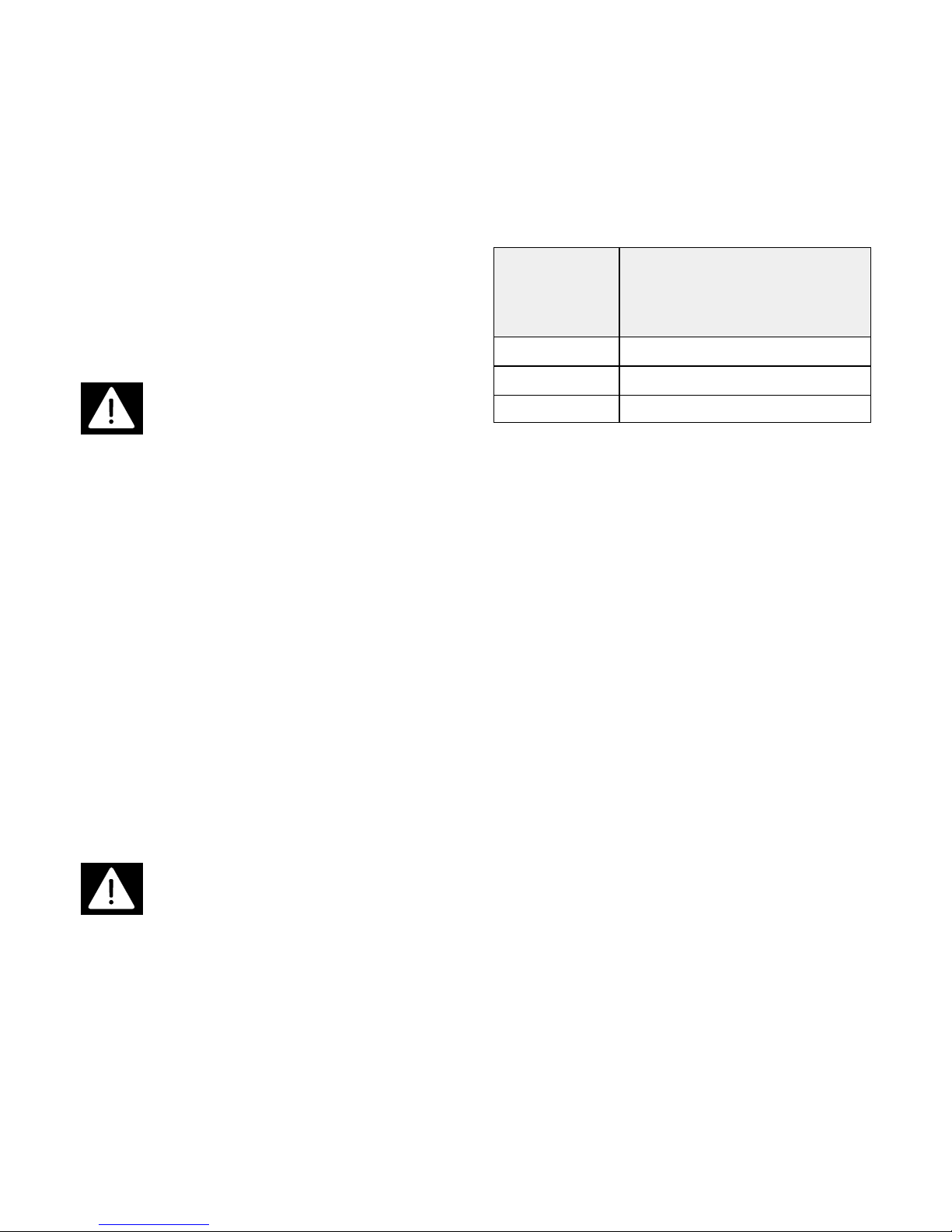
Per garantire un’adeguata ventilazione lasciare
uno spazio libero di almeno 1 unità rack (1U = 1,73”
= 44 mm) sopra e sotto l’apparecchio (g. 17, pag.
47). Quando è necessario installare nello stesso rack
molti amplicatori, è indispensabile utilizzare delle
ventole di rareddamento, per facilitare l’ingresso
dell’aria fresca e l’uscita dell’aria calda; nella tabella
seguente è indicato il numero massimo di
amplicatori installabili in un rack sprovvisto di
ventole di rareddamento.
Una soluzione potrebbe essere quella di installare
nel rack un pannello di aerazione con ventole nella
parte superiore, che provvede ad espellere l’aria
calda, ed un pannello di aerazione nella parte
inferiore (eventualmente anch’esso provvisto di
ventole), che permette l’ingresso dell’aria fresca (g.
17, pag. 47).
NUMERO MASSIMO DI
MODELLO AMPLIFICATORI INSTALLABILI IN
AMPLIFICATORE UN RACK SPROVVISTO DI
VENTOLE DI RAFFREDDAMENTO
UP 4061 6
UP 4121 3
UP 4161 2
Page 6

Collegamenti
ATTENZIONE: Per il collegamento
dell’apparecchio si raccomanda di
rivolgersi a personale qualicato ed
addestrato , ossia personale avente conoscenze
tecniche o esperienza o istruzioni speciche
sucienti per permettergli di realizzare
correttamente le connessioni e prevenire i pericoli
dell’elettricità.
Per evitare il rischio di shock elettrici,
l’apparecchio deve essere alimentato dalla tensione
di rete (115/230 Vac) solo dopo aver terminato tutti i
collegamenti.
Prima di alimentare l’apparecchio è buona norma
ricontrollare tutte le connessioni , vericando in
particolar modo che non vi siano dei cortocircuiti
accidentali.
Tutto l’impianto di sonorizzazione dovrà essere
realizzato in conformità con le norme e le leggi
vigenti in materia di impianti elettrici.
AVVERTENZA : Per evitare che fenomeni induttivi
diano luogo a ronzii, disturbi e compromettano il
buon funzionamento dell’apparecchio, i cavi che
trasmettono segnali microfonici o segnali a livello
linea (es. 0 dB=775 mV) devono essere schermati e
non devono essere posti in prossimità di:
1) apparecchiature che producono forti campi
magnetici (es. grossi trasformatori di alimentazione).
2) conduttori dell’energia elettrica.
3) linee che alimentano diusori.
Alimentazione in corrente alternata
ATTENZIONE: Prima di alimentare
l’apparecchio assicuratevi che la
tensione della vostra rete di
alimentazione corrisponda con la tensione impostata
dal selettore di tensione (24) (g. 1 - pag. 42), in
caso contrario rivolgetevi al vostro rivenditore
RCF S.p.A..
Collegate l’apparecchio a prese di corrente
provviste di contatto di terra.
Per il collegamento con la rete in corrente alternata
a 115 Vac o 230 Vac occorre utilizzare l’apposito cavo
fornito in dotazione, che dovrà essere
preventivamente connesso alla presa (23)
dell’apparecchio (g.1 - pag. 42).
6
Alimentazione in corrente continua
ATTENZIONE: Per evitare possibili
malfunzionamenti della sorgente di
alimentazione in corrente continua, non
alimentare l’apparecchio contemporaneamente con
corrente alternata e con corrente continua.
Si utilizzano i morsetti (10) (g. 1 - pag. 42) che
dovranno essere connessi ad una sorgente di
alimentazione a 24 Vdc (es. batteria), come indicato
in gura 2 a pagina 42. Premere il morsetto per poter
inserire il conduttore nell’apposito foro; rilasciare il
morsetto per fermare il conduttore. Per ridurre al
minimo le cadute di tensione ed evitare
surriscaldamenti, la sezione minima dei conduttori di
alimentazione deve essere di 1,5 mm2per UP 4061, e
2,5 mm2per UP 4121 e UP 4161.
Collegamento dell’ingresso “UNBALANCED
IN” e dell’uscita “PARALLEL OUT”
L’ingresso e l’uscita sono di tipo sbilanciato; le
connessioni della spina RCA da inserire in ciascuna
presa sono indicate nella gura 3, pag. 43. Per
selezionare la sensibilità dell’ingresso “UNBALANCED
IN” agire sul tasto (29) (g. 1, pag. 42).
Collegamento dell’ingresso
“BALANCED INPUT”
I collegamenti da eettuare sono indicati in gura
4, pag. 43. Per utilizzare l’ingresso “BALANCED IN”
prioritario sull’ingresso “UNBALANCED IN” occorre
connettere alla morsettiera “ INPUT” un contatto
normalmente aperto (NO) che, cortocircuitando fra
loro i morsetti “ PRIORITY ” e “ GND”, determina
l’esclusione dell’ingresso “UNBALANCED IN”, e la
conseguente diusione del loro segnale audio
relativo all’ingresso “BALANCED IN” per tutta la
durata del contatto (g. 5, pag. 43). Come organo di
comando elettrico è possibile impiegare il pulsante
ausiliario presente su alcune basi microfoniche, o un
normale interruttore per impianti elettrici.
Collegamento della morsettiera
“COMMANDS”
La funzione dei 4 morsetti è descritta nel paragrafo
“COMANDI E FUNZIONI”. In gura 6 a pagina 43 è
indicato il collegamento dell’ingresso “ STAND-BY”;
nelle gure 7 e 8 a pagina 44 sono indicati due
possibili connessioni dell’uscita “ OVERL.”:
collegamento con un led, oppure con un relè
ausiliario. Nel collegamento dell’uscita “ OVERL.”
tenere presente che:
– la corrente massima erogabile dall’uscita è di
300 mA.
– la tensione dell’uscita è di 18 Vdc; se viene
impiegato un relé a 12 Vdc, é quindi necessario
collegare una resistenza per determinare una caduta
Page 7

di tensione di 6 V. Utilizzando ad esempio un relé a
12 Vdc avente un assorbimento di 70 mA, la
resistenza da collegare deve avere un valore di 82
ohm - 1 W (6V : 0,07A = 85,7 ohm ⇒82 ohm).
Collegamento dei morsetti di uscita
“POWER OUTPUTS”
ATTENZIONE: Per evitare il rischio di
shock elettrici, non toccate mai i
conduttori nudi che fanno capo ai
morsetti di uscita dell’unità di potenza quando
quest’ultima è in funzione.
Terminati i collegamenti isolare i morsetti 50V,
70V, 100V dell’unità di potenza con l’apposito
coperchio di protezione.
Nelle gure 9, 10, 11, 12, 13 e 14 a pagina 44 e 45
sono indicati i possibili collegamenti dei morsetti per
diusori “POWER OUTPUTS” . Per accedere alle
uscite a tensione costante 50V, 70V, 100V, rimuovere
il coperchio di protezione svitando le 2 viti relative.
Linee ad impedenza costante
– L’impedenza complessiva dei diusori collegati
deve corrispondere a quella selezionata sui morsetti
d’uscita dell’unità di potenza.
– La somma delle potenze dei diusori non deve
essere inferiore alla potenza d’uscita
dell’apparecchio.
– La lunghezza dei cavi di collegamento deve
essere ridotta al minimo; in ogni caso maggiore è la
distanza da coprire e maggiore deve essere la
sezione dei cavi.
Linee a tensione costante
– Ciascun diusore deve essere munito di un
trasformatore di linea avente una tensione d’ingresso
pari a quella della linea (25V, 50V, 70V o 100V).
– La somma delle potenze dei diusori non deve
superare la potenza d’uscita dell’apparecchio.
NOTA: L’uscita “4 Ω” dell’apparecchio può essere
collegata anche su carichi aventi impedenza
maggiore (8 Ω, 16 Ω); la potenza di uscita si riduce di
conseguenza.
7
Protezione contro sovraccarichi
e cortocircuiti
L’apparecchio è completamente protetto nei
confronti di qualsiasi collegamento errato dei
diusori. Al suo interno infatti incorpora un ecace
circuito di protezione che interviene, interrompendo il
funzionamento dell’unità di potenza e accendendo la
spia “ OVERLOAD” sul pannello frontale,
ogniqualvolta venga riscontrata una delle seguenti
condizioni sulla linea d’uscita.
Uscite a tensione costante (25 - 50 - 70 - 100V)
– Potenza complessiva dei diusori superiore alla
potenza d’uscita dell’apparecchio.
– Cortocircuito fra i morsetti di uscita dell’unità di
potenza.
– Segnale d’ingresso troppo elevato con morsetti
di uscita scollegati.
Uscita ad impedenza costante (4 Ω)
– Impedenza complessiva dei diusori inferiore a 2
ohm.
– Cortocircuito fra i morsetti di uscita dell’unità di
potenza.
– Segnale d’ingresso troppo elevato con morsetti
di uscita scollegati.
L’unità di potenza è inoltre provvista della
protezione termica degli stadi nali: qualora l’unità di
potenza smetta improvvisamente di funzionare,
spegnere l’apparecchio, lasciarlo rareddare, e
controllare la linea di uscita per diusori per
eliminare possibili inconvenienti; se anche dopo
quest’ultima operazione l’apparecchio non riprende a
funzionare, rivolgersi ad un CENTRO DI ASSISTENZA
RCF S.p.A..
Page 8

Dati tecnici UP 4061 • UP 4121
UP 4161
Tipo
60 W - Monofonico - Da tavolo (UP 4061)
120 W - Monofonico - Da tavolo (UP 4121)
160 W - Monofonico - Da tavolo (UP 4161)
Potenza di uscita
nominale: 60 W - massima: 90 W
(10 msec ON - 0,1 sec OFF) (UP 4061)
nominale: 120 W - massima: 180 W
(10 msec ON - 0,1 sec OFF) (UP 4121)
nominale: 160 W massima: 220 W
(10 msec ON - 0,1 sec OFF) (UP 4161)
Risposta in frequenza
50 - 15.000 Hz (±3 dB)
Distorsione
≤1% (1 kHz - potenza nominale)
Rapporto segnale/rumore
≥ 80 dB
Ingressi/Sensibilità-Impedenza
Ingresso sbilanciato RCA:
775 mV - 50 k Ω
80 mV - 50 k Ω
Ingresso bilanciato su morsettiera
775 mV - 100 k Ω (bilan.)
Uscite per diusori / Ohm
4 Ohm
Uscite per diusori / Volt
25V - 50V - 70V - 100V
(10 Ω, 41 Ω, 80 Ω, 162 Ω) (UP 4061)
25V - 50V - 70V - 100V
(5Ω, 21 Ω, 41 Ω, 83 Ω) (UP 4121)
25V - 50V - 70V - 100V
(4Ω, 15,5 Ω, 30,5 Ω, 62 Ω) (UP 4161)
Uscite supplementari / Tens. - Imped.
RCA, in parallelo con l’ingresso sbilanciato
8
Uscita ausiliaria “overload”
18 Vdc - 300 mA
Controlli di tono
bassi ±12 dB - 100 Hz
alti ±12 dB - 10 kHz
Filtri
H.P.: 300 Hz / 12 dB/oct.
L.P.: 7 kHz / 12 dB/oct.
Controlli
1 controllo di volume generale
1 controllo toni alti
1 controllo toni bassi
Alimentazione / Consumo
115/230 Vac (±5%) 50/60 Hz / 180 VA (UP 4061)
115/230 Vac (±5%) 50/60 Hz / 450 VA (UP 4121)
115/230 Vac (±5%) 50/60 Hz / 550 VA (UP 4161)
Inrush current
I=20A (UP4061)
I=23A (UP4121)
I=25A (UP4161)
Assorbimento in continua (24 V)
5 A (UP 4061)
10 A (UP 4121)
14 A (UP 4161)
Temperatura ambiente massima
55°C
Dimensioni (lxaxp)
433 x 88 x 315 mm
Peso
9,4 kg (UP 4061)
11,4 kg (UP 4121)
12,9 kg (UP 4161)
Page 9
Sezione riservata ai Centri di
Assistenza RCF S.p.A.
ATTENZIONE: Le operazioni descritte in
questa sezione sono indirizzate
esclusivamente ai CENTRI DI ASSISTENZA
RCF S.p.A.. Le informazioni che
seguono NON INTERESSANO L’UTENTE che può
tralasciarne la lettura.
Prima di eettuare le operazioni descritte in questa
sezione è indispensabile scollegare il cavo di
alimentazione dalla rete in corrente alternata
(115/230 Vac).
Selezione della tensione di alimentazione
1) Spostare il selettore di tensione (24) (g. 1 - pag.
42) nella posizione corrispondente al valore
desiderato: “ 115V ” o “ 230V” indicato sulla slitta
del selettore.
2) Inserire nel portafusibile (22) (g. 1 - pag. 42) un
fusibile avente la portata adatta alla tensione di
alimentazione selezionata , come indicato sul
pannello posteriore dell’apparecchio.
Abilitazione della modalità “STAND-BY”
Sulla SCHEDA INGRESSI presente all’interno
dell’unità di potenza é presente un ponticello che
consente di abilitare la modalità “
stand-by
”.
1) Svitare le 4 viti poste su ciascun anco
dell’apparecchio, e rimuovere il coperchio.
9
2) Individuare all’interno dell’unità di potenza il
ponticello “ J1”, presente sulla SCHEDA INGRESSI
(g. 16, pag. 47).
3) Spostare il ponticello “ J1” dalla posizione “ A” alla
posizione “ B” (g. 16), in modo da cortocircuitare
il terminale centrale con l’altro terminale laterale.
4) Rimontare il coperchio dell’apparecchio.
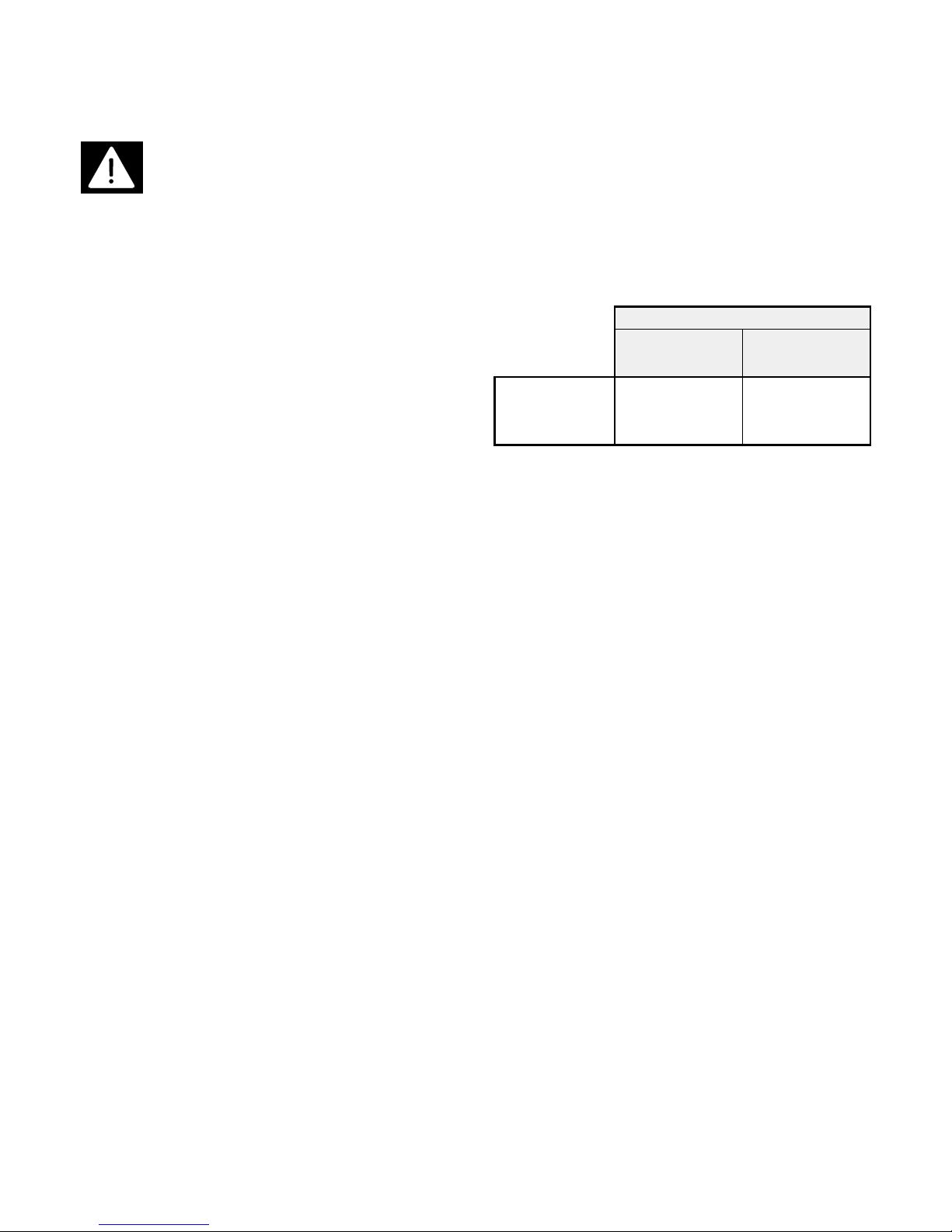
Tabella per gura 16
AVVERTENZA : Se si attiva la modalità “stand-by”, per
poter attivare l’unità di potenza è indispensabile
cortocircuitare fra loro i morsetti “ STAND-BY” (rif. 18
- g. 1) e “ GND” (rif. 19 - g. 1, pag. 42).
Declino di responsabilità
La RCF S.p.A. persegue una politica di costante ricerca e sviluppo, e nell’intento di migliorare i propri prodotti si
riserva il diritto apportare modiche estetiche o funzionali ai suoi prodotti in qualunque momento e senza preavviso.
RCF S.p.A.. Tutti i diritti riservati. Stampato in Italia.
POSIZIONE: A POSIZIONE: B
(default)
FUNZIONE
PONTICELLO
J1
Modalità
“stand-by”
disinserita .
Modalità
“stand-by”
inserita .
Page 10
IMPORTANT
Before connecting and using the amplier, please
read the instructions in this manual carefully and
keep it for future reference.
This manual is to be considered an integral part of
the product, and must accompany the amplier when
it changes ownership as a reference for correct
installation and use as well as for the safety
regulations.
RCF S.p.A. will not assume any
responsibility for incorrect amplier installation.
WARNING : To prevent the risk of re or
electric shock, never expose the unit to
rain or humidity.
Safety Precautions
1. Please read the notes preceded by the symbol
with special attention , as they provide
important safety information.
2. The power supply voltage of this unit has a
suciently high value to involve a risk of
electrocution; therefore, never install, connect, or
disconnect of the unit with the power supply
switched on.
3. Before powering up the power amplier, make
sure that the mains voltage corresponds to the
voltage value set on the selector (ref. 24, Fig. 1 pag. 42). If not, ask your RCF S.p.A. dealer
to congure the unit for the correct
voltage.
4. The metallic parts of the unit are earthed by
means of the power cable. If the current outlet
used for supplying the unit does not provide an
earth connection, contact a qualied electrician
to earth the unit using the terminal (13) (Fig. 1pag. 42).
5. To protect the power supply cable from being
damaged, make sure that it is positioned so that
it cannot be stepped on or crushed by objects.
6. To prevent the risk of electrical shock, never open
the unit. There are no parts inside the unit that
need to be accessed by the user.
7. Make sure that no objects or liquids can get into
the unit, as this may cause a short circuit.
8. Never attempt to make any repairs that are not
described in this manual. Contact your authorized
service centre or qualied personnel should any
of the following occur:
A. The unit does not function (or functions in an
anomalous way).
10
ENGLISH
B. The power supply cable has been damaged.
C. Objects or liquids have got into the unit.
D. The unit has been subject to heavy impact.
9. When the unit is not to be used for long periods of
time, disconnect the power supply cable.
10. If the unit should emit any strange odours or
smoke, switch it o immediately and disconnect
the power supply cable.
11. To prevent risk of electric shock, never connect or
disconect the power cable with wet hands.
Always grasp the plug directly; never pull on the
cable itself.
12. Never point any type of spray directly at the unit
(e.g. insecticides, cleaning products, etc.), as the
gas used in these products could catch re
suddenly.
Operating precautions
Do not obstruct the ventilation grilles of the unit.
Do not force the power amplier to work in
overload for long periods of time.
Tighten the speaker terminals thoroughly in order
to ensure a perfect contact.
Never force the control elements (buttons, control
knobs, etc.).
Do not use solvents, alcohol, benzene, or other
volatile substances to clean the exterior parts of the
unit.
Description
The 4000 series power ampliers have been
specically designed for the transmission of
microphone announcements and/or musical
programmes in all PA systems. They incorporate the
following features:
- 1 unbalanced RCA input
- 1 balanced input on terminal strip
- 1 RCA output in parallel with the unbalanced
input
- Possibility to give the balanced input priority over
the unbalanced input
- RCA input sensitivity selectable between 0 dB and
-20 dB
- Outputs for speakers with constant impedance
(4 Ohm) and constant voltage (25-50-70-100 V)
- Stand-by mode which makes it possible to switch
the unit on by remote control (excludable)
- Auxiliary output for overload indication
- H.P. (high pass) and L.P. (low pass) lters
- Bass and treble controls
- STD-BY, OVERLOAD, SIGNAL , and PEAK indicator
lights
Page 11

- Dual power supply in alternating current
(115/230 Vac)
- 24 Vdc power supply
- Removable front knobs, with closure caps
Controls and functions
(Fig. 1 - page 42)
1) Bass tone control
This knob emphasizes (clockwise rotation) or
attenuates (anti-clockwise rotation) the low
frequencies. With the knob in the central position,
the frequency response is not altered. To prevent
the level from being modied, the knob can be
removed and the hole can be covered using the
special cap supplied.
2) Treble tone control
This knob emphasizes (clockwise rotation) or
attenuates (anti-clockwise rotation) the high
frequencies. With the knob in the central position,
the frequency response is not altered. To prevent
the level from being modied, the knob can be
removed and the hole can be covered using the
special cap supplied.
3) Master volume control
This knob is used for adjusting the nal volume of
the signal present on the speaker POWER
OUTPUTS (ref. 12 and 14). To prevent the master
volume from being modied, the knob can be
removed and the hole can be covered using the
special cap supplied.
4) POWER switch
For switching the power amplier on and o.
5) “STD-BY” light
This led lights up when the unit is in “stand-by”
mode.
6) OVERLOAD indicator light
This light comes on when the power amplier is
operating in overload, a condition which is
generally caused by a problem on the speaker
line.
NOTE: When the power amplier is switched on,
the OVERLOAD light comes on for a few seconds,
but this is part of normal operation and does not
indicate a problem, as a preliminary test is carried
out each time the power amplier is switched on.
7) SIGNAL light
This light comes on when the audio signal is
ready on the POWER OUTPUTS of the speakers.
8) PEAK light
This light comes on when the volume is set at to
excessively high levels, and the audio signal on
the speaker outputs is distorted. For correct use
11
of the power amplier, it is necessary to adjust
the master volume in such a way as not to cause
this light to come on, though momentary lighting
up is acceptable.
9) ON light
This light comes on when the power amplier is
switched on.
10) Terminals for direct current supply
These two terminals enable the power amplier to
be supplied in direct current by means of an
external 24 Vdc source (e.g. 24 V battery).
Whenever the alternating current is interrupted,
the power amplier is automatically supplied in
direct current, thus ensuring continuous
operation.
NOTE: The unit is not equipped with a battery
charging device for the external battery source,
and thus it is advisable to have an appropriate
charger on hand.
11) DC protection fuse
The fuse that protects the direct current power
supply circuits of the power amplier can be
accessed by removing the fuse-holder. The fuse
must only be replaced by an
RCF S.p.A. SERVICE CENTRE.
12) Output terminals
These four terminals are used for connecting the
speakers to the 50V, 70V, and 100V outputs.
13) Earth terminal
Used for earthing the metallic parts of the unit
when the current outlet used for power supply is
not equipped with an earth terminal. This
connection must only be made by a qualied
electrician.
14) Output terminals
These three terminals are used for connecting
speakers to the 4 ohm and 25V outputs.
15) "PRIORITY" terminal
Short circuiting this terminal with terminal (16)
(e.g. using an electrical contact) activates the
priority function of BALANCED IN over
UNBALANCED IN, which completely excludes the
latter input (no signal transmitted). This function
can be used, for instance, for transmitting alarm
signals or microphone announcements. In this
case, the UNBALANCED INmust be connected to
the musical source to be used and the BALANCED
IN must be connected to an amplied microphone
stand or an alarm source.
16) "GND" terminal
Earth terminal, common to the BALANCED INand
PRIORITY inputs.
Page 12

17) "BALANCED IN" input
Used for connecting the device that supplies the
audio signal to be amplied (preamplier, mixer,
another power amplier, etc.). This socket can be
used in alternative to the UNBALANCED IN, or
both inputs can be used with the "priority"
function, which gives BALANCED INpriority over
UNBALANCED IN(see "PRIORITY terminal"). The
input can accept balanced signals at 0 dB.
18) "STAND-BY" terminal
In order to use this terminal, the "stand-by" mode
must be activated by the RCF S.p.A. SERVICE
CENTRE. This function makes it
possible to switch on the power amplier by
remote control. When the unit is switched on
using the POWER switch (ref. 4 - Fig. 1), it
automatically goes into stand-by mode, and
operation is blocked; to control amplication and
signal transmission, the terminals STAND-BY and
GND (ref. 19) must be short circuited together,
e.g. using an electrical contact.
19) "GND" terminal
Earth terminal for the STAND-BY input.
20) "OVERL." terminal
When the overload protection circuit is tripped
and the power amplier stops working, the
OVERLOAD light on the front panel comes on, and
a voltage of 18 Vdc (max. 300 mA) is made
available on the OVERL. output which can be used
for driving a LED or an auxiliary relay.
21) "GND" terminal
Earth terminal for the OVERL. output.
22) AC protection fuse
The fuse that protects the alternating current
power supply circuits of the power amplier can
be accessed by removing the fuse holder. In the
event of a blown fuse or a change in the supply
voltage, the fuse must only be replaced by an
RCF S.p.A. SERVICE CENTRE.
23) Power cable socket
For connecting the power cable supplied with the
power amplier.
24) Supply voltage selector
Used for selecting the supply voltage for the
power amplier between 115 Vac and 230 Vac.
The selection must only be made by an
RCF S.p.A. SERVICE CENTRE.
12
25) H.P. switch
When this switch is lowered, a high-pass lter is
activated which attenuates all frequencies lower
than 300 Hz. This lter can be useful for
improving voice intelligibility in spaces that are
particularly subject to reverberation. Using the
H.P. and L.P. lters together makes it possible to
correctly drive horn speakers which have a
limited frequency response and can thus be
damaged when driven with excessively high or
low frequencies.
26) L.P. switch
When this switch is lowered, a low-pass lter is
activated which attenuates all frequencies higher
than 7 kHz. This lter can be useful for
eliminating acoustic feedback from speakers to
microphones.
27) "UNBALANCED IN" input
This coaxial RCA socket is used for connection
with the device that supplies the unbalanced
audio signal to be amplied (preamplier, mixer,
another power amplier, etc.). This socket can be
used in alternative to the BALANCED IN, or both
inputs can be used with the "priority" function,
which gives BALANCED INpriority over
UNBALANCED IN(see "PRIORITY terminal"). Using
the SENSITIVITY switch, the sensitivity level of the
input can be selected between -20 dB and 0 dB.
28) "PARALLEL OUT" output
This coaxial RCA output is connected in parallel
with input (27), and can be used for sending the
audio input signal to another power amplier, a
supplementary amplier, etc..
29) "SENSITIVITY" switch
This switch is used for selecting the sensitivity of
the UNBALANCED INbetween the values of 0 dB
and -20 dB; the latter value makes it possible to
connect equipment that has a particularly low
output level (e.g. 80 mV).
Page 13
Installation
The amplier is supplied with rubber feet which
make it possible to set the unit directly on a table or
shelf. Position the unit horizontally on a sturdy, at
surface. To ensure normal cooling of the unit, choose
a position that is well-ventilated, not exposed to
direct sunlight, and far from any heat source.
WARNING : To prevent the unit from
overheating, it is essential to leave a free
space of at least 5 cm (2”) behind the
rear panel and in front of the side panels, and at least
15 cm (6”) above the upper panel; in any case, never
situate the unit inside a completely closed structure.
Do not situate the unit in places that are subject to
high-intensity vibrations or particularly exposed to
dust or humidity.
NOTE: The UP 4061, UP 4121, and UP 4161
ampliers are cooled by natural convection : the cool
air enters the unit through the air vents situated on
the lower part, and the heated air from the internal
heat dissipaters leaves the unit through the air vents
located on the upper cover. This system avoids the
need for periodic air lter cleaning which is typical of
fan-cooling systems, and also reduces dust intake
into the unit.
Rack installation
WARNING : To install the amplier in a
rack, only use a rack enclosure that is
equipped with air vents and which fully
satises the requirements of the EN 60439-1
standard.
To install the amplier in a rack in the space of two
units (2U = 3.5” = 88 mm), you need to purchase the
AR 1052-N accessory (code no. 173.10.059) and
carefully follow the instructions provided with the
accessory. The amplier must be attached securely to
the rack, especially when the rack will be frequently
moved or transported. When arranging the
equipment in the rack enclosure, place heavier
equipment in the lower part and lighter equipment in
the upper part.
13
To ensure adequate ventilation, leave a free space
of at least one rack unit (1U = 1.73” = 44 mm) above
and below the unit (see Fig. 17, pag. 47). When
multiple ampliers are to be installed in the rack, it is
essential to use cooling fans in order to facilitate cool
air intake and hot air outtake. The table below shows
the maximum number of ampliers that can be
installed in a rack which is not equipped with cooling
fans.
One solution could be to install a ventilation panel
with fans in the upper part of the rack which will
expel the hot air, and a ventilation panel in the lower
part (where necessary also equipped with fans) to
allow cool air intake (see Fig. 17, page 47).
MAXIMUM NUMBER
AMPLIFIER OF AMPLIFIERS THAT CAN BE
MODEL INSTALLED IN A RACK NOT
EQUIPPED WITH COOLING FANS
UP 4061 6
UP 4121 3
UP 4161 2
Page 14

Connections
WARNING : For connecting the
equipment, use only qualied and
experienced installers, or personnel
having sucent technical knowledge or specic
instructions to make the connections correctly in
order to prevent electrical dangers.
To prevent the risk of electrical shock, the power
amplier must be supplied with the mains voltage
(115/230 Vac) only after all connections have been
made.
Before powering up the equipment, it is advisable
to re-check all connections , making sure there are no
accidental short circuits.
The entire sound system must be designed and
installed in compliance with the current laws and
regulations on electrical systems.
IMPORTANT NOTE : To prevent inductive phenomena
from giving rise to hum or disturbance which would
jeopardize ecient system operation, the cables that
transmit microphone signals or line level signals (e.g.
0 dB=775 mV) should not be run in the vicinity of:
1) equipment that produces strong magnetic elds
(e.g. large power transformers)
2) electrical energy conductors
3) speaker supply lines.
AC Power supply
WARNING : Before supplying the
equipment, make sure that your mains
voltage corresponds with the value set
on the voltage selector (24) (Fig. 1-pag. 42). If not,
contact your RCF S.p.A. SERVICE CENTRE.
Connect the amplier to current outlets equipped
with an earth contact.
For connecting with the mains at 115 Vac or 230
Vac, use the cable supplied with the unit, which
should rst be connected to the socket (23) on the
power amplier (Fig. 1- pag. 42).
14
DC Power supply
WARNING : To prevent possible
malfunctions of the direct current power
supply source, do not supply the
equipment with alternating and direct current at the
same time.
For the DC power supply, use the terminals (10)
(Fig. 1 - pag. 42), which must be connected to a 24
Vdc source (e.g. battery) as shown in Fig. 2 - pag. 42.
Press the terminal down to insert the wire in the hole
and release the terminal to clamp the wire. To reduce
voltage drops to the minimum and prevent
overheating, the minimum cross-section of the supply
wires should be 1.5 mm2for the UP 4061, and 2.5
mm2for UP 4121 and UP 4161.
"UNBALANCED IN" and "PARALLEL OUT"
connection
The input and output are unbalanced; the
connections of the RCA plug to be connected to each
socket are shown in Figure 3 - page 43. To select the
sensitivity of the UNBALANCED IN, use the switch (29)
(Fig. 1 - page 42).
"BALANCED INPUT" connection
The connections to be made are shown in Figure 4 page 43. To use the BALANCED IN with priority over
the UNBALANCED IN, a normally open contact (NO)
must be connected to the INPUT terminal strip. By
short circuiting the PRIORITY and GND terminals
together, the UNBALANCED INis excluded and only
the signal related to the BALANCED IN is transmitted
for the entire duration of the contact (see Fig. 5 - page
43). The auxiliary pushbutton on certain microphone
stands or a normal electrical switch can be used as an
electrical control device for this purpose.
"COMMANDS" terminals strip connection
The function of the 4 terminals is described in the
section "CONTROLS AND FUNCTIONS". Figure 6 - page
43 shows the connection of the STAND-BY input.
Figures 7 and 8 - page 44 show two possible
connections for the OVERL. output: with a LED or with
an auxiliary relay. In the OVERL. output connection,
keep in mind the following points:
- the maximum current that can be delivered by
the output is 300 mA.
- the voltage of the output is 18 Vdc; if a 12 Vdc
relay is used, it is therefore necessary to connect a
resistor in order to have a 6 V voltage drop. For
example, using a 12 Vdc relay with absorption of 70
mA, the resistor to be connected must have a value of
82 ohm - 1 W (6V : 0.07A = 85.7 ohm ⇒82 ohm).
Page 15

Connecting the “POWER OUTPUTS” terminals
WARNING : To prevent the risk of electric
shock, never touch the bare wires coming
from the output terminals of the power
amplier when it is switched on.
When the connections have been made, insulate
the 50V, 70V, and 100V terminals of the power
amplier using the special protective cover.
Figures 9, 10, 11, 12, 13 and 14 - pag. 44 and 45
show the possible connections of the “POWER
OUTPUTS” terminals for speakers. To access the 50V,
70V, and 100V constant voltage outputs, remove the
protective cover by unscrewing the two screws.
Constant impedance line
- The total impedance of the speakers connected
must correspond to that selected on the output
terminals of the power amplier.
- The sum of the power values of the speakers
must not be less than the output power of the power
amplier.
- The length of the connection cables must be
reduced to the minimum; in any case, the greater the
distance to be covered, the greater the cable crosssection should be.
Constant voltage line
- Each speaker must be equipped with a line
transformer having an input voltage equal to that of
the line (25V, 50V, 70V, or 100V).
- The sum of the power values of the speakers
must not exceed the output power of the power
amplier.
NOTE: The “4 Ω ” output of the unit can also be
connected to loads having a greater impedence
(8 Ω , 16 Ω ); the output power is reduced as a
conseguence.
15
Protection against Overloads
and short circuits
The power amplifer is completely protected against
any incorrect connection of the speakers, as it
incorporates an ecient protection circuit which
interrupts operation and switches on the OVERLOAD
light on the front panel whenever any of the following
conditions occur:
Constant voltage outputs (25 - 50 - 70 - 100 V)
- the total power of the speakers is greater than
the power amplier output power.
- short circuit between the power amplier output
terminals.
- Input signal too high with output terminals
disconnected
Constant impedance output (4 ohms)
- the total impedance of the speakers is less than
2 Ohms.
- short circuit between the power amplier output
terminals.
- input signal too high with output terminals
disconnected.
The power amplier is also eqiupped with an
thermal protection circuit for the nal stages. When
the unit stops working suddenly, switch it o, let it
cool, and check the speaker output line to eliminate
any possible problems. If the unit does not return to
normal operation after this check, contact your
RCF S.p.A. SERVICE CENTRE.
Page 16

UP 4061 • UP 4121 • UP 4161
Specications
Type
60 W - Mono - Table-top (UP 4061)
120 W - Mono - Table-top (UP 4121)
160 W - Mono - Table-top (UP 4161)
Output power
nominal: 60 W - maximum: 90 W
(10 msec ON - 0,1 sec OFF) (UP 4061)
nominal: 120 W - maximum: 180 W
(10 msec ON - 0,1 sec OFF) (UP 4121)
nominal: 160 W - maximum: 220 W
(10 msec ON - 0,1 sec OFF) (UP 4161)
Frequency response
50 - 15,000 Hz (± 3 dB)
Distortion
≤ 1% (1 kHz - nominal power)
Signal/noise ratio
≥ 80 dB
Inputs/Sensitivity - Impedance
Unbalanced RCA, input
775 mV - 50 k Ω
80 mV - 50 k Ω
Balanced input on terminals strip:
775 mV - 100 k Ω (bal.)
Outputs for speakers / ohms
4 Ω
Outputs for speakers / volts
25V - 50V - 70V - 100V
(10 Ω, 41 Ω, 80 Ω, 162 Ω) (UP 4061)
25V - 50V - 70V - 100V
(5Ω, 21 Ω, 41 Ω, 83 Ω) (UP 4121)
25V - 50V - 70V - 100V
(4Ω, 15,5 Ω, 30,5 Ω, 62 Ω) (UP 4161)
Supplementary outputs/Voltage -Impedance
RCA, in parallel with unbalanced input
16
Auxiliary output “Overload”
18 Vdc - 300 mA
Tone controls
bass: ± 12 dB - 100 Hz
treble: ± 12 dB - 10 kHz
Filters
H.P.: 300 Hz / 12 dB/oct.
L.P.: 7 kHz / 12 dB/oct.
Controls
1 master volume
1 treble
1 bass
Power supply / Consumption
115/230 Vac (±5%) 50/60 Hz / 180 VA (UP 4061)
115/230 Vac (±5%) 50/60 Hz / 450 VA (UP 4121)
115/230 Vac (±5%) 50/60 Hz / 550 VA (UP 4161)
Inrush current
I=20A (UP4061)
I=23A (UP4121)
I=25A (UP4161)
Absorption in DC (24 V)
5 A (UP 4061)
10 A (UP 4121)
14 A (UP 4161)
Maximum ambient temperature
55° C
Dimensions (lxhxd)
433 x 88 x 315 mm
Weight
9,4 kg (UP 4061)
11,4 kg (UP 4121)
12,9 kg (UP 4161)
Page 17

Section reserved to the
RCF S.p.A. Service Centre
WARNING: The operations described in
this section are for the exclusive use of
the RCF S.p.A. SERVICE CENTRE.
The information given here is OF NO
INTEREST TO THE USER , who need not read it.
Before carrying out the operations described in
this section, it is absolutely indispensable to
disconnect the power cable from the AC mains
(115/230 Vac).
Selecting the supply voltage
1) Move the voltage selector (24) (Fig. 1- pag. 42) to
the position corresponding to the desired value:
“115V ” or “ 230V ”.
2) Insert a fuse into the fuse-holder (22) (Fig.1 - pag.
42) having a suitable capacity for the supply
voltage selected , as indicated on the adhesive
label on the rear panel of the power amplier.
Enabling "STAND-BY" mode
A jumper on the INPUT BOARD inside the power
amplier is used for enabling "stand-by" mode.
1) Unscrew the 4 screws on the sides of the unit and
remove the cover.
17
2) Locate the " J1" jumper situated inside the unit on
the INPUT BOARD (Fig. 16, pag. 47).
3) Move the " J1" jumper from position A to position
B (Fig. 16) to short circuit the middle terminal
with the other side terminal.
4) Re-t the cover.
Table for Figure 16
NOTE: When the "stand-by" mode is enabled, in order
to switch on the power amplier it is necessary to
short circuit together the STAND-BY (ref. 18 - Fig. 1,
page 42) and GND (ref. 19 - Fig. 1) terminals
Disclaimer
RCF S.p.A. applies a company policy based on constant research and development. With the aim of constantly
improving our products, we reserve the right to make any aesthetic or functional modications at any time and without prior notice.
RCF S.p.A.. All rights reserved. Printed in Italy.
POSITION: A POSITION: B
(default)
FUNCTION
J1 JUMPER
“Stand-by” mode
not enabled.
“Stand-by” mode
enabled.
Page 18

18
IMPORTANT
Avant de brancher et d'utiliser l’appareil, lisez
attentivement les instructions contenues dans ce
manuel, que nous vous conseillons de conserver pour
le consulter plus tard.
Ce manuel fait partie intégrante du produit et doit
suivre celui-ci même dans les passages de propriété,
pour permettre au nouveau propriétaire de connaître
les modalités de montage et d’emploi ainsi que les
consignes de sécurité.
Une mauvaise installation de l’appareil décharge
RCF S.p.A. de toute responsabilité.
ATTENTION: Pour prévenir les risques de
ammes ou décharges électriques, ne
laissez pas l’appareil à la pluie ni à
l’humidité.
Consignes de securite
1. Lisez très attentivement toutes les mises en
garde accompagnées du symbole car elles
contiennent des renseignements importants pour
votre sécurité et celle des autres.
2. La tension d’alimentation de l’appareil est
susamment élevée pour représenter un risque
d’électrocution pour les personnes. Coupez
toujours l’alimentation avant d’installer ou de
brancher l’appareil.
3. Avant d’alimenter l’appareil, vériez si votre
tension de secteur correspond à la tension
établie par le sélecteur de tension (réf. 24 - g. 1
- pag. 42) sinon, adressez-vous à votre revendeur
RCF S.p.A. pour qu’il règle
l’appareil sur la bonne tension.
4. Les parties métalliques de l’appareil résultent
reliées à la terre par le cordon d’alimentation. Si la
prise de courant utilisée pour l’alimentation ne
fournit pas de mise à la terre, contactez un
électricien qualié pour qu’il branche l’appareil à
la terre au moyen de la borne (13) (g. 1 - pag. 42).
5. Veillez à ce que le cordon d’alimentation de
l’appareil ne soit ni piétiné ni écrasé par quoi que
ce soit et qu’il reste parfaitement indemne.
6. Pour éviter les risques de chocs électriques,
n’ouvrez jamais l’appareil . Ce que vous trouveriez
à l’intérieur ne vous servirait à rien.
7. Evitez que tout objet ou liquide pénètre dans
l’appareil, ce qui risquerait de provoquer un
court-circuit.
FRANÇAIS
8. N’essayez pas d’eectuer des réparations si elles
ne sont pas décrites dans ce manuel. Adressezvous aux centres après-vente agréés ou à des
spécialistes si :
A. L’appareil ne fonctionne pas (ou fonctionne
mal) ;
B. Le cordon d’alimentation est fortement
endommagé ;
C. Des objets ou des liquides ont pénétré dans
l’appareil ;
D. L’appareil a subi des chocs importants.
9. Si l’appareil reste inactif pendant de longues
périodes, coupez la tension sur le l
d’alimentation.
10. Si l’appareil dégage des odeurs anormales ou s’il
en sort de la fumée, éteignez-le immédiatement
et coupez la tension sur le l d’alimentation.
11. Pour ne pas risquer de chocs électriques, éviter
de brancher et de débrancher le cordon
d’alimentation les mains mouillées . Saisissez
toujours directement la che et ne tirez jamais
sur le l.
12. Evitez de diriger le jet du vaporisateur sur
l’appareil (insecticides, produits d’entretien, etc.)
car les gaz utilisés pourraient prendre feu à
l’improviste.
Précautions
N’obstruez pas les grilles de ventilation de
l’appareil.
Evitez de faire longtemps travailler en surcharge
l’unité de puissance.
Serrez à bloc les bornes à enceintes pour assurer
le contact.
Ne forcez pas les organes de commandes (touches,
contrôles, etc.)
Pour le nettoyage des parties extérieures, évitez
les diluants, l’alcool, l’essence ou autres substances
volatiles.
Description
Les unités de puissance de la série 4000 ont été
expressément conçues pour diuser des annonces
et/ou des programmes de musique dans tous les
systèmes de sonorisation ‘PA’. Leurs fonctions sont
les suivantes :
- 1 entrée RCA asymétrique.
- 1 entrée symétrique sur bornier.
- 1 sortie RCA en parallèle avec l’entrée
asymétrique.
- Possibilité de rendre l’entrée symétrique
prioritaire sur l’entrée asymétrique.
Page 19

19
- Sélection de la sensibilité de l’entrée RCA entre 0
dB et - 20 dB.
- Sorties pour enceintes à impédance constante (4
ohm ) et à tension constante (25 - 50 - 70 - 100 V).
- Modalité “stand-by” qui permet de
télécommander la mise en marche de l’appareil (peut
s’exclure).
- Sortie auxiliaire pour signalisation “overload”.
- Filtres passe-haut (H.P.) et passe-bas (L.P.).
- Contrôle des tons aigus et graves.
- Témoins “STD-BY”, “OVERLOAD”, “SIGNAL”,
“PEAK”.
- Double alimentation en courant alternatif (115/
230 Vca).
- Alimentation en courant continu 24 V.
- Boutons détachables de la façade et bouchons.
Commandes et fonctions
(g. 1 - pag. 42)
1) Contrôle des graves
Ce bouton exalte (rotation dans le sens des
aiguilles d’une montre) ou atténue (rotation en
sens inverse) les basses fréquences. Si le bouton
est au centre, la bande passante ne s’altère pas.
Pour éviter de modier le niveau, vous pouvez
enlever le bouton et boucher le trou sur le
panneau avec le bouchon fourni en dotation.
2) Contrôle des aigus
Ce bouton exalte (rotation dans le sens des
aiguilles d’une montre) ou atténue (rotation en
sens inverse) les hautes fréquences. Si le bouton
est au centre, la bande passante ne s’altère pas.
Pour éviter de modier le niveau, vous pouvez
enlever le bouton et boucher le trou sur le
panneau avec le bouchon fourni en dotation.
3) Contrôle de volume général
Ce bouton permet de régler le niveau nal du
signal sur les sorties pour enceintes “POWER
OUTPUTS” (réf. 12 et 14). Pour éviter de modier
le niveau, vous pouvez enlever le bouton et
boucher le trou sur le panneau avec le bouchon
fourni en dotation.
4) Interrupteur “POWER”
Il permet d’allumer et d’éteindre l’appareil.
5) Témoin “STD-BY”
Le témoin s’allume quand l’unité de puissance est
en “STAND-BY”
6) Témoin “OVERLOAD”
Ce témoin s’allume pour indiquer que l’unité de
puissance travaille en surcharge. Cette condition
est généralement provoquée par un problème sur
la ligne des enceintes.
MISE EN GARDE: Quand l’unité de puissance se
met en marche, le témoin “ OVERLOAD” s’allume
quelques secondes. Ce n’est pas un signe de
problème mais un comportement tout à fait
normal de l’appareil qui eectue un test initial à
chaque fois que l’unité de puissance s’allume.
7) Témoin “SIGNAL”
Le témoin s’allume quand le signal sonore est
disponible sur la sortie pour enceintes “POWER
OUTPUTS”.
8) Témoin “PEAK”
Ce témoin s’allume quand le volume est réglé à
des niveaux trop élevés et que le signal sonore
sur les sorties pour enceintes est distordu. Pour
utiliser correctement l’unité de puissance, réglez
le volume général de manière que le témoin ne
s’allume pas. Il est en tout cas acceptable que le
témoin s’allume de temps en temps.
9) Témoin “ON”
Le témoin s’allume quand l’unité de puissance est
en marche.
10) Bornes pour alimentation en courant continu
Les deux bornes permettent d’alimenter l’unité de
puissance en courant continu, au moyen d’une
source extérieure de 24 Vcc (ex. batterie de 24 V).
Si le courant alternatif s’interrompt, l’appareil est
automatiquement alimenté en courant continu, et
la continuité de fonctionnement est assurée.
MISE EN GARDE : L’appareil n’est pas équipé de
dispositif pour recharger l’éventuelle batterie
d’alimentation. Il y a lieu par conséquent de
prévoir un appareil adéquat.
11) Fusible de protection C.C.
Dévisser le porte-fusible pour accéder au fusible
qui protège les circuits d’alimentation en courant
continu de l’appareil. Le fusible ne peut être
remplacé que par un CENTRE APRES-VENTE
RCF S.p.A..
12) Bornes de sortie
Les 4 bornes permettent de brancher des
enceintes acoustiques sur les sorties 50 V, 70 V,
100 V.
13) Borne de terre
Elle permet de mettre à la terre les parties
métalliques de l’appareil, si la prise de courant
utilisée pour l’alimentation n’a pas de terre. La
connexion doit être eectuée par un électricien
qualié.
14) Bornes de sortie
Les 3 bornes permettent de brancher les
enceintes acoustiques sur les sorties 4 ohms et
25 V.
Page 20

15) Borne “PRIORITY”
En court-circuitant cette borne avec la borne (16)
(avec un contact électrique, par exemple) vous
activerez la fonction de priorité de l’entrée
“BALANCED IN” sur l’entrée “UNBALANCED IN” ,
qui exclura complètement cette dernière (aucun
signal diusé). La fonction peut s’exploiter pour
diuser des signaux d’alarme ou des annonces
au micro : dans ce cas l’entrée “UNBALANCED IN”
devra recevoir la source musicale à diuser tandis
que l’entrée “BALANCED IN” devra recevoir une
base micro ampliée ou une source d’alarme.
16) Borne “GND”
Borne de masse, commune pour les entrées
“BALANCED IN” et “ PRIORITY ”.
17) Entrée “BALANCED IN”
Cette entrée doit recevoir l’appareil qui fournit le
signal audio à amplier (préamplicateur,
mélangeur, autre unité de puissance, etc.). Vous
pouvez utiliser cette prise comme alternative à
l’entrée “UNBALANCED IN” ou les utiliser toutes
les deux grâce à la fonction “priority” qui rend
l’entrée “BALANCED IN” prioritaire sur l’entrée
“UNBALANCED IN” (Cf. le point “Borne
PRIORITY”). L’entrée peut accepter des signaux
symétriques au niveau 0 dB.
18) Borne “STAND-BY”
Pour utiliser la borne, adressez-vous à un
CENTRE APRES-VENTE RCF S.p.A. qui
activera la modalité “stand-by”. Cette modalité
permet de télécommander la mise en marche de
l’unité de puissance : si vous allumez l’appareil à
l’interrupteur “ POWER” (Réf. 4) il se met
automatiquement en “stand-by” et il s’arrête de
fonctionner. Pour commander l’amplication et la
diusion du signal, court-circuitez entre elles les
bornes “ STAND-BY” et “ GND” (réf. 19) avec, par
exemple, un contact électrique.
19) Témoin “GND”
Borne de masse, commune pour l’entrée “ STANDBY”.
20) Borne “OVERL.”
Quand le circuit de protection contre les
surcharges se déclenche et que l’unité de
puissance s’arrête, le témoin “ OVERLOAD”
s’allume sur le panneau de façade et la sortie
“OVERL.” peut disposer d’une tension de 18 V c.c.
(300 mA max. ) utilisable pour piloter une DEL ou
un relais auxiliaire.
21) Témoin “GND”
Borne de masse, commune pour la sortie
“OVERL.”
22) Fusible de protection C.A.
Dévissez le porte-fusible pour accéder au fusible
qui protège les circuits d’alimentation de
20
l’appareil en courant alternatif. En cas de panne
ou de changement de tension d’alimentation, le
fusible ne pourra être remplacé que par un
spécialiste du CENTRE APRES-VENTE RCF S.p.A..
23) Prise pour le cordon d’alimentation
Elle permet de brancher le cordon d’alimentation
fourni en dotation.
24) Sélecteur de la tension d’alimentation
Ce sélecteur permet de choisir la tension
d’alimentation de l’appareil entre 115 V ou 230 V
ca. La sélection de la tension d’alimentation ne
peut être faite que par un spécialiste du CENTRE
APRES-VENTE RCF S.p.A..
25) Touche “H. P.”
Baissée, elle introduit un ltre passe-haut qui
atténue toutes les fréquences inférieures à 300
Hz. Le ltre peut être utile pour améliorer
l’intelligibilité de la voix dans les milieux
particulièrement réverbérants. Utilisé en
association avec le ltre “ L.P .”, il permet de
piloter correctement les enceintes à pavillon qui,
caractérisées par une bande passante limitée,
pourraient se détériorer si elles étaient pilotées à
des fréquences trop hautes ou trop basses.
26) Touche “L. P.”
Baissée, elle introduit un ltre passe-bas qui
atténue toutes les fréquences supérieures à 7
kHz. Le ltre peut être utile pour éliminer les
phénomènes de feed-back (retours acoustiques
des enceintes aux micros).
27) Entrée “UNBALANCED IN”
La prise coaxiale RCA permet de brancher
l’appareil qui fournit le signal audio asymétrique
à amplier (préamplicateur, mélangeur, autre
unité de puissance, etc.). Vous pouvez utiliser
cette prise comme alternative à l’entrée
“BALANCED IN” ou les utiliser toutes les deux
grâce à la fonction “priority” qui rend l’entrée
“BALANCED IN” prioritaire sur l’entrée
“UNBALANCED IN” (Cf. le point “Borne
PRIORITY”). La touche “ SENSITIVITY ” permet de
sélectionner la sensibilité de - 20 à 0 dB.
28) Sortie “PARALLEL OUT”
La sortie coaxiale RCA est reliée en parallèle à
l’entrée (27) et peut s’utiliser pour envoyer le
signal audio en entrée à une autre unité de
puissance, à un amplicateur supplémentaire,
etc.
29) Touche “SENSITIVITY”
La touche permet de choisir la sensibilité de
l’entrée “UNBALANCED IN” entre 0 et - 20 dB.
Cette dernière valeur permet de brancher les
appareils possédant un niveau de sortie
particulièrement bas (ex. 80 mV).
Page 21

Installation
L’appareil est fourni avec des pieds en caoutchouc
qui permettent de le poser directement sur les
rayonnages. Le placer à l’horizontale, sur une surface
rigide et plane. Pour assurer un bon refroidissement
de l’appareil, choisir un endroit bien ventilé, à l’abri
des rayons de soleil et loin de toute source de
chaleur.
ATTENTION: Pour éviter de surchauer
l’appareil, il est impératif de laisser un
espace derrière le panneau arrière et de
chaque côté d’au moins 5 cm (2’’) et d’au moins 15
cm (6’’) au-dessus du panneau supérieur. Ne jamais
placer l’appareil dans des structures entièrement
fermées.
Evitez d’installer l’appareil dans des endroits
subissant de fortes vibrations ou particulièrement
humides ou poussiéreux.
NOTA: Les amplicateurs de puissance UP 4061, UP
4121, UP 4161 sont refroidis par convection
naturelle : l’air frais entre dans les appareils par les
grilles de ventilation situées dans le bas, et l’air
surchaué par les dissipateurs de chaleur internes
sort par les grilles de ventilation qui se trouvent dans
le couvercle du haut.
Ce système évite le nettoyage périodique des
ltres, typique des systèmes de refroidissement par
ventilateurs, et réduit la pénétration de poussière
dans les appareils.
Installation en baie
ATTENTION: Pour l’installation en baie,
l’appareil devra être muni de grilles
d’aération et être conforme à la norme
EN 60439-1.
Pour installer l’appareil en baie, dans l’espace de
deux racks (2 U = 3,5’’ = 88 mm) acheter l’accessoire
AR 1052-N (code 173.10.059) et suivre
scrupuleusement les instructions qui
l’accompagnent. Fixer l’appareil de façon sûre,
surtout si le rack doit être fréquemment déplacé ou
transporté. Dans l’installation en baie, placer les
appareils les plus lourds en bas et les plus légers en
haut.
21
Pour garantir une ventilation adéquate, laisser un
espace d’au moins 1 unité rack (1 U = 1,73’’ = 44
mm) au-dessus et au-dessous de l’appareil (g. 17,
pag. 47). Pour installer de nombreux amplicateurs
dans le même rack, il est indispensable d’utiliser
des ventilateurs de refroidissement , pour faciliter
l’entrée d’air frais et la sortie d’air chaud. Le tableau
suivant indique le nombre maximal d’amplicateurs
que peut loger un rack sans ventilateurs de
refroidissement.
Une solution possible consisterait à installer, dans
le haut du rack, un panneau à ventilateurs pour
chasser l’air chaud et, dans le bas, un panneau
(éventuellement à ventilateurs aussi) pour faire
pénétrer l’air frais (g. 17, page 47).
NOMBRE MAXI. D’AMPLIFICATEURS
MODELE QUE PEUT LOGER UN RACK SANS
AMPLIFICATEUR VENTILATEURS DE
REFROIDISSEMENT
UP 4061 6
UP 4121 3
UP 4161 2
Page 22

Branchements
ATTENTION: Pour brancher l’appareil,
adressez-vous à un spécialiste qualié et
bien formé, c’est-à-dire à une personne
ayant de l’expérience ou des connaissances
techniques, ou ayant reçu des instructions
spéciques qui lui permettent de réaliser
correctement les connexions et de prévenir les
dangers de l’électricité.
Pour éviter les risques de chocs électriques,
terminez toutes les connexions avant de brancher
l’appareil sur le secteur 115/230 Vca.
Avant d’alimenter l’appareil, il est de bonne règle
de recontrôler toutes les connexions et de s’assurer
en particulier qu’il n’y a pas de courts-circuits
accidentels.
Tout le système électrique devra être réalisé
conformément aux normes et aux lois en vigueur en
matière d’installations électriques.
MISE EN GARDE : Pour éviter que des phénomènes
inductifs provoquent des bourdonnements,
perturbent et compromettent le bon fonctionnement
de l’appareil, blindez les ls qui transmettent des
signaux microphoniques ou des signaux au niveau de
la ligne (0 dB=775 mV) et évitez de les poser à
proximité de :
1) appareils produisant de forts champs
magnétiques (gros transformateurs d’alimentation) ;
2) conducteurs de l’énergie électrique.
3) lignes qui alimentent les enceintes.
Alimentation en courant alternatif
ATTENTION: Avant d’alimenter votre
appareil, vériez si votre tension de
secteur correspond à celle qui est
établie par le sélecteur de tension (24) (g. 1 - pag.
42). Si elles sont diérentes, adressez-vous à votre
revendeur RCF S.p.A..
Branchez l’appareil sur des prises de courant ayant
la terre.
Pour vous brancher sur secteur en courant
alternatif à 115 ou 230 V utilisez le cordon spécial
fourni en dotation, que vous devrez d’abord brancher
sur la prise (23) de l’appareil (g. 1 - pag. 42).
22
Alimentation en courant continu
ATTENTION: Pour éviter de détériorer la
source d’alimentation en courant continu,
évitez d’alimenter l’appareil en même
temps en courant alternatif et en courant continu.
Utilisez les bornes (10) (g. 1 - pag. 42) qui devront
être reliées à une source d’alimentation de 24 Vcc
(batterie), comme l’indique la g. 2 - pag. 42. Presser
la borne pour pouvoir introduire le conducteur dans
l’orice prévu. Lâchez la borne pour bloquer le
conducteur. Pour réduire au minimum les chutes de
tension et éviter les surchaues des conducteurs
d’alimentation, la section minimum de ceux-ci doit
être de 1,5 mm2pour l’UP 4061 et de 2,5 mm2pour
l’UP 4121 et l’UP 4161.
Branchement de l’entree “UNBALANCED IN”
et de la sortie “PARALLEL OUT”
L’entrée et la sortie sont asymétriques. La gure 3 pag. 43 indique les branchements de la che RCA à
eectuer sur chaque prise. Pour sélectionner la
sensibilité de l’entrée “UNBALANCED IN” agissez sur
la touche (29) (g. 1 - pag. 42).
Branchement de l’entree “BALANCED INPUT”
La gure 4 - pag. 43 indique les branchements à
eectuer. Pour utiliser l’entrée “BALANCED IN”
prioritaire sur l’entrée “UNBALANCED IN” , branchez
sur le bornier “ INPUT” un contact normalement
ouvert (NO) qui, en court-circuitant entre elles les
bornes “ PRIORITY “ et “ GND”, provoquera l’exclusion
de l’entrée “UNBALANCED IN” et diusera
uniquement le signal audio relatif à l’entrée
“BALANCED IN” et ce, tant que durera le contact (g.
5 - pag. 43). Comme organe de commande électrique
vous pouvez utiliser le bouton auxiliaire qui se trouve
sur certaines bases microphoniques ou un simple
interrupteur pour systèmes électriques.
Branchement du bornier “COMMANDS”
Le paragraphe “COMMANDES ET FONCTIONS décrit
la fonction des quatre bornes. La gure 6 - pag. 43
indique le branchement de l’entrée “ STAND-BY” et
les gures 7 et 8 - pag. 44 indiquent les deux
branchements possibles de la sortie “ OVERL.” : une
DEL ou un relais auxiliaire. Si vous branchez la sortie
“OVERL.”, n’oubliez pas que :
- le courant maximum qu’elle peut fournir est de
300 mA.
- la tension de sortie est de 18 V c.c. . Si vous
utilisez un relais à 12 V c.c., vous devrez relier une
résistance pour provoquer une chute de tension de 6
V. Si nous prenons par exemple un relais à 12 V c.c.
ayant une absorption de 70 mA, la résistance à relier
devra avoir une valeur d’au moins 82 ohm - 1 W (6 V :
0,07 A = 85,7 ohm⇒82 ohm).
Page 23

Branchement des bornes de sortie
“POWER OUTPUTS”
ATTENTION: Pour éviter les risques de
chocs électriques, ne touchez jamais aux
conducteurs dénudés qui sortent des
bornes de sortie de l’unité de puissance si celui-ci est
en marche.
Après avoir terminé les branchements, isolez les
bornes 50 V, 70 V et 100 V de l’unité de puissance
avec les capuchons prévus.
Les gures 9, 10, 11, 12, 13 et 14 - pag. 44 et 45
indiquent les branchements possibles des bornes
pour enceintes “POWER OUTPUTS”. Pour accéder aux
sorties à tension constante 50 V, 70 V, 100 V,
dévissez les 2 vis du capuchon et enlevez celui-ci.
Ligne à impédance constante
- L’impédance globale des enceintes reliées doit
correspondre à celle qui est sélectionnée sur les
bornes de sortie de l’unité de puissance.
- La somme des puissances des enceintes ne doit
pas être inférieure à la puissance de sortie de
l’appareil.
- La longueur des ls de branchement doit être
réduite au minimum ; en tout cas, la grosseur de la
section des ls doit être proportionnelle à la distance
à couvrir.
Ligne à tension constante
- Chaque enceinte doit être équipée d’un
transformateur de ligne ayant une tension d’entrée
égale à celle de la ligne (25, 50, 70 ou 100 V.).
- La somme des puissances des enceintes ne doit
pas dépasser la puissance de sortie de l’appareil.
NOTE: La sortie “4 Ω” de l’appareil peut se brancher
également sur des charges ayant une impédance plus
grande (8 Ω, 16 Ω), puissance de sortie de réduira en
conséquence.
23
Protection contre les
surcharges et les courtscircuits
L’appareil est complètement protégé de tout
mauvais branchement des enceintes. En eet, il
incorpore un circuit ecace de protection qui se
déclenche, interrompt le fonctionnement de l’unité de
puissance et allume le témoin “ OVERLOAD” sur le
panneau de façade à chaque fois que se présente
l’une des situations suivantes sur la ligne de sortie :
Sorties à tension constante (25 - 50 - 70 - 100 V)
- Puissance globale des enceintes supérieure à la
puissance de sortie de l’appareil
- Court-circuit entre les cosses de sortie de l’unité
de puissance.
- Signal d’entrée trop eléve, bornes de sortie
débranchées.
Sortie à impédance constante (4 Ohms)
- Impédance globale des enceintes inférieure à 2
Ohms.
- Court-circuit entre les cosses de sortie de l’unité
de puissance.
- Signal d’entrée trop eléve, bornes de sortie
débranchées.
L’unité de puissance possède également une
protection thermique des étages de sortie. Si l’unité
de puissance se bloque à l’improviste, éteignez
l’appareil et laissez-le refroidir. Vérier la ligne de
sortie pour enceintes et éliminez les éventuels
problèmes. Si malgré cette opération elle ne repart
pas, adressez-vous à un CENTRE APRES-VENTE
RCF S.p.A..
Page 24

Caracteristiques techniques
UP 4061 • UP 4121 • UP 4161
Type
60 W - Mono - De table (UP 4061)
120 W - Mono - De table (UP 4121)
160 W - Mono - De table (UP 4161)
Puissance de sortie
nominale: 60 W - maximum: 90 W
(10 msec ON - 0,1 sec OFF) (UP 4061)
nominale: 120 W - maximum: 180 W
(10 msec ON - 0,1 sec OFF) (UP 4121)
nominale: 160 W - maximum: 220 W
(10 msec ON - 0,1 sec OFF) (UP 4161)
Bande passante
De 50 à 15.000 Hz (± 3 dB)
Distorsion
≤ 1% (1 kHz - puissance nominale)
Rapport signal / bruit
≥ 80 dB
Entrées / Sensibilité / Impédance
Entrée asymétrique RCA:
775 mV - 50 k Ω
80 mV - 50 k Ω
Entrée symetrique sur bornier
775 mV - 100 k Ω (sym.)
Sorties pour enceintes /Ohms
4 Ω
Sorties pour enceintes / Volts
25V - 50V - 70V - 100V
(10 Ω, 41 Ω, 80 Ω, 162 Ω) (UP 4061)
25V - 50V - 70V - 100V
(5Ω, 21 Ω, 41 Ω, 83 Ω) (UP 4121)
25V - 50V - 70V - 100V
(4Ω, 15,5 Ω, 30,5 Ω, 62 Ω) (UP 4161)
Sorties supplémentaires
RCA, en parallèle avec l’entrée asymétrique
24
Sortie auxiliaire “Overload”
18 Vcc - 300 mA
Réglage de ton
graves ± 12 dB - 100 Hz
aigus ± 12 dB - 10 kHz
Filtres
P.H. : 300 Hz / 12 dB/oct.
L.P. : 7 kHz / 12 dB/oct.
Contrôles
1 contrôle de volume général
1 contrôle des aigus
1 contrôle des graves
Alimentation / Consommation
115/230 Vac (±5%) 50/60 Hz / 180 VA (UP 4061)
115/230 Vac (±5%) 50/60 Hz / 450 VA (UP 4121)
115/230 Vac (±5%) 50/60 Hz / 550 VA (UP 4161)
Inrush current
I=20A (UP4061)
I=23A (UP4121)
I=25A (UP4161)
Absorption en continu (24 V)
5 A (UP 4061)
10 A (UP 4121)
14 A (UP 4161)
Température ambiante maximum
55°
Dimensions (l x h x p)
433 x 88 x 315 mm
Poids
9,4 kg (UP 4061)
11,4 kg (UP 4121)
12,9 kg (UP 4161)
Page 25

Déni de responsabilité
La RCF S.p.A. suit une politique de recherche et développement constant et, soucieuse d’améliorer ses produi ts, elle
se réserve le droit d’apporter des modications esthétiques et fonctionnelles à tout moment et sans préavis.
RCF S.p.A.. Tous droits réservés. Imprimé en Italie.
Section reservee aux centre
apres-vente RCF S.p.A.
ATTENTION: Les opérations décrites dans
ce chapitre s’adressent exclusivement
aux CENTRES APRES-VENTE RCF S.p.A..
Les informations qui suivent
NE REGARDENT PAS L’UTILISATEUR. Celui-ci pourra
par conséquent éviter de les lire.
Avant d’eectuer les opérations décrites ici, il est
indispensable de débrancher le cordon
d’alimentation de courant alternatif (115 / 230 Vca).
Selection de la tension d’alimentation
1) Mettez le sélecteur de tension (24) (g. 1 - pag.
42) sur la position correspondant à la valeur
souhaitée :” 115 V” ou “ 230 V”.
2) Introduisez dans le porte-fusible (22) (g. 1 - pag.
42) un fusible d’une capacité adéquate à la
tension d’alimentation sélectionnée , comme
l’indique la plaque adhésive appliquée au
panneau arrière de l’appareil.
Activation de la modalite “STAND-BY”
La CARTE ENTREES , à l’intérieur de l’unité de
puissance, présente un pontet qui permet d’activer la
modalité “stand-by”.
1) Dévissez les 4 vis de chaque côté de l’appareil et
enlevez le couvercle.
25
2) A l’intérieur de l’unité de puissance, trouvez le
pontet “J1” sur la CARTE ENTREES (g. 16, pag.
47).
3) Déplacez le pontet “ J1” de “A” à “ B” (g. 16) pour
court-circuiter la cosse centrale avec l’autre cosse
latérale.
4) Remontez le couvercle de l’appareil.
Tableau gure 16
MISE EN GARDE : La modalité “stand-by” étant
activée, il sera indispensable, pour activer l’unité de
puissance, de court-circuiter entre elles les bornes
“STAND-BY” (réf. 18 - g. 1, pag. 42) et “ GND” (réf.
19 - g. 1).
POSITION: A POSITION: B
(default)
FUNCTION
PONTET
J1
Modalité
“stand-by”
débranchée.
Modalité
“stand-by”
branchée.
Page 26

WICHTIG
Vor dem Anschließen und der Benutzung des
Gerätes die im vorliegenden Handbuch enthaltenen
Anweisungen aufmerksam lesen und dasselbe für
zukünftige Konsultationen aufbewahren.
Das vorliegende Handbuch stellt einen integralen
Bestandteil des Produkts dar und muss dasselbe
auch bei einem Wechsel des Eigentümers begleiten,
um es dem neuen Besitzer zu ermöglichen, sich über
die Installation, die Benutzung sowie die zu
beachtenden Hinweise zur Sicherheit zu informieren.
Eine unsachgemäße Installation des Gerätes
entbindet RCF S.p.A. von jeglicher Haftung.
ACHTUNG: Zur Vermeidung der Gefahr
von Flammen oder elektrischen Schlägen
das Gerät nicht dem Regen oder der
Feuchtigkeit aussetzen.
Sicherheitshinweise
1. Alle Hinweise, die mit dem Symbol
gekennzeichnet sind, müssen besonders
aufmerksam gelesen werden, da sie wichtige
Informationen zur Sicherheit enthalten.
2. Die Betriebsspannung des Geräts ist ausreichend
hoch, um für Personen eine Fulgorationsgefahr
darzustellen: Nehmen Sie die Installation oder den
Anschluss nie mit eingeschalteter Speisung vor.
3. Stellen Sie vor der Benutzung des Geräts sicher,
dass ihre Netzspannung der auf dem
Spannungswahlschalter eingestellten
Betriebsspannung entspricht (24 - Abbildung 1 -
Seite 42) und wenden Sie sich anderenfalls an
Ihren RCF S.p.A.-Händler,
der das Gerät auf die richtige Spannung
einstellen wird.
4. Die metallischen Teile des Geräts werden über
das Netzkabel geerdet. Falls die Netzsteckdose
nicht geerdet ist, so müssen Sie sich an einen
qualizierten Elektriker wenden, der das Gerät
über die Schraube (13 - Abbildung 1 - Seite 42)
erdet.
5. Stellen Sie sicher, dass das Netzkabel des Geräts
nicht gequetscht oder auf sonstige Weise
beschädigt werden kann, damit seine
Unversehrtheit gewährleistet ist.
6. Önen Sie das Gerät nie , um die Gefahr von
elektrischen Schlägen zu vermeiden: Im Innern
benden sich keine Bauteile, die vom Benutzer
verwendet werden können.
26
DEUTSCH
7. Verhindern Sie, dass Gegenstände oder
Flüssigkeiten ins Innere des Geräts gelangen, da
dadurch Kurzschlüsse ausgelöst werden könnten.
8. Versuchen Sie nicht, Reparaturen durchzuführen,
die in diesem Handbuch nicht beschrieben
werden; wenden Sie sich an eine autorisierte
Kundendienststelle oder an einen hoch
qualizierten Fachmann, wenn:
A. das Gerät nicht (oder nicht normal)
funktioniert;
B. das Speisungskabel schwer beschädigt
worden ist;
C. Gegenstände oder Flüssigkeiten in das Gerät
eingedrungen sind;
D. das Gerät starke Stöße erfahren hat.
9. Schalten Sie die Spannung von dem
Speisungskabel ab, wenn das Gerät für einen
längeren Zeitraum nicht benutzt wird.
10. Schalten Sie sofort die Spannung von dem
Speisungskabel ab , wenn anomale Gerüche oder
Rauch aus dem Gerät kommen.
11. Zur Vermeidung von elektrischen Schlägen das
Netzkabel nie mit nassen Händen einstecken
oder herausziehen ; immer direkt am Stecker und
nie am Kabel selbst ziehen.
12. Nicht direkt auf das Gerät sprühen (zum Beispiel
Insektizide, Reinigungsmittel msw.): Die
enthaltenen Gase könnten sich entzünden.
Vorsichtsmassnahmen bei der
Benutzung
Verstopfen Sie die Lüftungsschlitze des Geräts
nicht.
Vermeiden Sie es, den Leistungseinheiten über
einen längeren Zeitraum im Überlastbetrieb
einzusetzen.
Ziehen Sie die Klemmen für den Anschluss der
Lautsprecherbox gut fest, um einen sicheren Kontakt
zu gewährleisten
Bewegen Sie die Bedienungselemente (Tasten,
Regler usw.) nicht mit Gewalt.
Vermeiden Sie bei der Reinigung der Außenächen
die Verwendung von Alkohol, Benzin oder sonstigen
üchtigen Substanzen.
Beschreibung
Die Leistungseinheiten der Baureihe 4000 wurden
eigens für die Wiedergabe von Stimme und Musik in
allen PA-Anwendungen entwickelt. Sie bieten
folgende Funktionen:
- 1 unsymmetrischer RCA-Eingang;
- 1 symmetrischer Eingang an Klemmenleiste;
Page 27

- 1 RCA-Ausgang parallel zum unsymmetrischen
Eingang;
- Möglichkeit der Vorrangschaltung des
symmetrischen Eingangs gegenüber dem
unsymmetrischen Eingang;
- Empndlichkeit des RCA-Eingangs einstellbar auf
0 dB oder -20 dB;
- Lautsprecherausgänge mit konstanter Impedanz
(4 Ω) und konstanter Spannung (25 - 50 - 70 - 100 V);
- "Stand-by"-Funktion für die Ferneinschaltung des
Geräts (ausschaltbar);
- Hilfsausgang für die Überlast-Anzeige;
- Hochpaßlter und Tiefpaßlter;
- Klangregler für Höhen und Bässe;
- Kontrolleuchten " STD-BY", "OVERLOAD",
"SIGNAL" und " PEAK".
- Doppelte Wechselstromspeisung (115 / 230 Vac);
- Gleichstromspeisung 24 Vdc;
- Frontregler abnehmbar, mit Verschlußkappen.
Bedienungselemente und
Funktionen
(Abbildung 1 - Seite 42)
1) Regler Bässe
Der Regler verstärkt (Drehen nach rechts) oder
dämpft (Drehen nach links) die tiefen Frequenzen.
Mit dem Knauf in der Mittelstellung wird der
Frequenzgang nicht geändert. Zur Vermeidung
einer Verstellung der Einstellung kann der Knauf
abgenommen werden und die Bohrung in der
Front kann durch den entsprechenden
mitgelieferten Stopfen verschlossen werden.
2) Regler Höhen
Der Regler verstärkt (Drehen nach rechts) oder
dämpft (Drehen nach links) die hohen
Frequenzen. Mit dem Knauf in der Mittelstellung
wird der Frequenzgang nicht geändert. Zur
Vermeidung einer Verstellung der Einstellung
kann der Knauf abgenommen werden und die
Bohrung in der Front kann durch den
entsprechenden mitgelieferten Stopfen
verschlossen werden.
3) Regler allgemeine Lautstärke
Dieser Knauf gestattet die Einstellung der
Endverstärkung des gemischten Signals aller
Eingänge, das an die Anschlüsse für die
Lautsprecherboxen “POWER OUTPUTS” (12 und
14) geleitet wird. Zur Vermeidung einer
Verstellung der Einstellung kann der Knauf
abgenommen werden und die Bohrung in der
Front kann durch den entsprechenden
mitgelieferten Stopfen verschlossen werden.
4) Schalter “POWER”
Der Schalter gestattet das Ein- und Ausschalten
des Geräts.
27
5) Kontrolleuchte “STD-BY”
Diese Kontrolleuchte leuchtet auf, wenn sich die
Leistungseinheit im STAND-BY Modus bendet.
6) Kontrollleuchte “OVERLOAD”
Das Aueuchten dieser Kontrollleuchte zeigt an,
das der Leistungseinheiten im Überlastbetrieb
betrieben wird. Dies wird normalerweise durch
ein Problem auf der Lautsprecherleitung
verursacht.
HINWEIS : Beim Einschalten des
Leistungseinheiten leuchtet die Kontrollleuchte
“OVERLOAD” für einige Sekunden auf: Dies zeigt
keine Funktionsstörung an, sondern gehört zur
normalen Betriebsweise des Geräts, das bei
jedem Einschalten des Leistungseinheitens einen
Funktionstest durchführt.
7) Kontrollleuchte “SIGNAL”
Diese Kontrollleuchte leuchtet auf, wenn am
Ausgang für die Lautsprecherbox “POWER
OUTPUTS” ein Audiosignal anliegt.
8) Kontrollleuchte “PEAK”
Diese Kontrollleuchte leuchte auf, wenn die
Lautstärke zu hoch eingestellt worden und das
Signal an den Ausgängen für die
Lautsprecherboxen verzerrt ist. Für eine korrekte
Einstellung des Leistungseinheiten muss der
Hauptlautstärkeregler so eingestellt werden, dass
diese Kontrollleuchte nicht aueuchtet; eine
gelegentliches Aufblinken der Kontrollleuchte
kann jedoch hingenommen werden.
9) Kontrollleuchte ON
Die Kontrollleuchte leuchtet auf, wenn der
Leistungseinheiten eingeschaltet ist
10) Klemmen für die Speisung mit Gleichstrom
Die beiden Klemmen gestatten die Speisung des
Leistungseinheiten mit Gleichstrom über eine
externe 24 V-Quelle (zum Beispiel 24 V). Bei
Ausfällen des Wechselstroms wird das Gerät
automatisch auf den Gleichstrombetrieb
umgeschaltet, um einen unterbrechungsfreien
Betrieb zu gewährleisten.
HINWEIS : Das Gerät verfügt nicht über ein Gerät
zum Nachladen der eventuell verwendeten
Batterie und es wird daher empfohlen, ein
entsprechendes Gerät bereitzuhalten.
11) Gleichstromsicherung
Beim Herausschrauben des Sicherungshalters
wird die Sicherung zugänglich, die die
Schaltungen bei Speisung des Geräts mit
Gleichstrom schützt. Die Ersetzung darf
ausschließlich von einer RCF S.p.A.
Kundendienststelle vorgenommen werden.
Page 28

12) Ausgangsklemmen
Die vier Klemmen gestatten den Anschluss der
Lautsprecherboxen an die Ausgänge 50V, 70V
und 100V.
13) Erdungsklemme
Gestattet die Erdung der metallischen Teile des
Geräts, falls die zur Speisung verwendete
Netzsteckdose keine Erdung aufweist. Der
Anschluss darf ausschließlich von einem
qualizierten Elektriker vorgenommen werden.
14) Ausgangsklemmen
Die drei Klemmen gestatten den Anschluss der
Lautsprecherboxen an die Ausgänge 4 Ω und 25 V.
15) Klemme "PRIORITY"
Schließt man diese Klemme mit Klemme (16) kurz
(z.B. durch ein Schaltstück), hat der Eingang
"BALANCED IN" den Vorrang gegenüber dem
Eingang "UNBALANCED IN" , der vollständig
ausgeschaltet wird (kein Wiedergabesignal).
Diese Funktion ist zum Beispiel für die
Wiedergabe von Alarmsignalen oder
Mikrofonansagen von Nutzen: in diesem Fall muß
an den Eingang "UNBALANCED IN" die
Musikquelle und an den Eingang "BALANCED IN"
die verstärkte Mikrofoneinheit oder eine
Alarmquelle angeschlossen werden.
16) Klemme "GND”
Masseklemme, gemeinsam für die Eingänge
"BALANCED IN" und "PRIORITY".
17) Eingang "BALANCED IN"
An diesen Eingang muß das Gerät angeschlossen
werden, das das zu verstärkende Audiosignal
liefert (Vorverstärker, Mischer, zweite
Leistungseinheit usw.). Diese Buchse kann
alternativ zum Eingang "UNBALANCED IN"
verwendet werden. Außerdem können dank der
Vorrangfunktion (Priority), die dem Eingang
"BALANCED IN" den Vorrang gegenüber dem
Eingang "UNBALANCED IN" gibt (siehe Abs.
Klemme "PRIORITY "), beide Eingänge verwendet
werden. Der Eingang kann symmetrische Signale
mit einem Pegel von 0 dB empfangen.
18) Klemme "STAND-BY"
Für die Verwendung dieser Klemme muß man
durch ein RCF S.p.A.-KUNDENDIENSTZENTRUM
die Stand-by-Funktion aktivieren lassen.
Diese Funktion ermöglicht die
Ferneinschaltung der Leistungseinheit: wenn das
Gerät mit dem EIN-Schalter " POWER"
eingeschaltet wird (Pos. 4), schaltet es
automatisch auf Stand-by, d.h. es ist auf
Bereitschaft geschaltet und nicht in Betrieb. Zum
Steuern der Verstärkung und der Tonwiedergabe
muß man die Klemmen "STAND-BY" und "GND"
(Pos. 19) z.B. durch ein Schaltstück kurzschließen.
28
19) Klemme "GND"
Masseklemme für den Eingang "STAND-BY".
20) Klemme "OVERL."
Wenn die Überlastschutzschaltung anspricht und
die Leistungseinheit ausgeschaltet wird, leuchtet
auf dem vorderen Bedienfeld des Geräts die
Kontrolleuchte " OVERLOAD" auf. Am Ausgang
"OVERL." liegt dann eine Spannung von 18 V DC
(max. 300 mA) an, mit der eine LED oder ein
Hilfsrelais angesteuert werden kann.
21) Klemme "GND”
Masseklemme für den Ausgang " OVERL."
22) Wechselstromsicherung
Beim Herausnehmen des Sicherungshalters wird
die Sicherung zugänglich, die die Schaltungen
bei Speisung des Geräts mit Wechselstrom
schützt. Falls die Sicherung defekt ist oder
aufgrund eines Wechsels der Betriebsspannung
gewechselt werden muss, so darf diese Ersetzung
ausschließlich von einer RCF S.p.A.
Kundendienststelle vorgenommen werden.
23) Anschluss für Netzkabel
Gestattet das Anschließen des mitgelieferten
Netzkabels.
24) Wahlschalter Betriebsspannung
Der Wahlschalter gestattet die Wahl der
Betriebsspannung des Geräts zwischen den
Werten 115 Vac und 230 Vac. Die Wahl der
Betriebsspannung darf ausschließlich von einer
RCF S.p.A.-Kundendienststelle vorgenommen werden.
25) Taste “H.P.”
Durch Drücken dieser Taste wir ein Hochpasslter
der alle Frequenzen unter 300 Hz abschwächt.
Der Filter kann zur Verbesserung von
Wortbeiträgen in besonders schallenden Räumen
verwendet werden. Zusammen mit dem Filter
“L.P.” verwendet gestattet der Filter “ H.F.” eine
korrekte Ansteuerung von Hornlautsprechern, die
sich durch einen begrenzten Frequenzgang
auszeichnen und durch zu hohe oder zu tiefe
Frequenzen beschädigt werden könnten
26) Taste “L.P.”
Durch Drücken dieser Taste wir ein Tiefpasslter
der alle Frequenzen über 7 kHz abschwächt. Der
Filter kann zur Reduzierung von FeedbackPhänomenen (Rückkopplung von
Lautsprecherbox und Mikrofon) verwendet
werden.
27) Eingang "UNBALANCED IN"
Die RCA-Koaxialbuchse ermöglicht den Anschluß
eines Geräts, das ein zu verstärkendes
unsymmetrisches Audiosignal liefert
(Vorverstärker, Mischer, zweite Leistungseinheit
usw.). Diese Buchse kann alternativ zum Eingang
Page 29

"BALANCED IN" verwendet werden. Außerdem
können dank der Vorrangfunktion (Priority), die
dem Eingang "BALANCED IN" den Vorrang
gegenüber dem Eingang "UNBALANCED IN" gibt
(siehe Abs. Klemme " PRIORITY "), beide Eingänge
verwendet werden. Mit der Taste " SENSITIVITY "
kann die Empndlichkeit des Eingangs auf einen
der beiden Werte -20 dB oder 0 dB eingestellt
werden.
28) Ausgang "PARALLEL OUT"
Der RCA-Koaxialausgang ist mit dem Eingang (27)
parallel geschaltet und kann verwendet werden,
um ein am Eingang anliegendes Audiosignal zu
einer zweiten Leistungseinheit, zu einem
zusätzliche Verstärker usw. zu senden.
29) Taste "SENSITIVITY"
Mit dieser Taste kann man die Empndlichkeit
des Eingangs "UNBALANCED IN" auf einen der
Werte 0 dB oder -20 dB einstellen. Der
letztgenannte Wert erlaubt den Anschluß von
Geräten mit einem besonders niedrigen
Ausgangspegel (z.B. 80 mV).
Installation
Das Gerät wird mit Gummifüßchen geliefert, die die
direkte Aufstellung auf einer starren und ebenen
Oberäche gestatten. Zur Gewährleistung der
Kühlung des Gerätes eine gut belüftete Position
wählen, die nicht der direkten Sonnenbestrahlung
ausgesetzt ist und die sich nicht in der Nähe von
Wärmequellen bendet.
ACHTUNG: Zur Vermeidung von
Überhitzungen des Gerätes muss hinter
der Rückwand sowie an den Seiten ein
Abstand von zumindest 5 cm (2‘‘) eingehalten
werden, und über dem oberen Paneel muss ein
Abstand von zumindest 15 cm (6‘‘) eingehalten
werden; auf keinen Fall sollte das Gerät in einem
vollständig geschlossenen Behälter aufgestellt
werden.
Das Gerät nie an Orten aufstellen, die starke
Vibrationen aufweisen oder die in besonderer Weise
Staub und Feuchtigkeit ausgesetzt sind.
ANMERKUNG : Die Leistungsverstärker UP 4061, UP
4121 und UP 4161 werden durch natürliche
Konvektion gekühlt : Die frische Luft tritt durch die
Lüftungsroste im untern Teil ein und die von den
Wärmedissipatoren erwärmte Luft tritt durch die
Lüftungsroste in der oberen Abdeckung aus. Dieses
System macht ein regelmäßiges Reinigen der
Luftlter überüssig, das für Kühlsysteme mit
Gebläse typisch ist, und verringert das Eindringen
von Staub in das Gerät.
29
Installation in 19”-Behältern
ACHTUNG: Bei der Installation des
Gerätes in 19”-Behältern Behälter mit
Lüftungsrosten verwenden, die den
Anforderungen der Norm EN 60439-1 entsprechen.
Bei der Installation des Gerätes in 19”-Behältern
im Raum von zwei Einheiten (2 Einheiten = 88 mm)
den Zubehörartikel AR 1052-N (Bestellnummer
173.10.059) erwerben und die Anweisungen genau
einhalten, die mit demselben geliefert werden. Das
Gerät sicher befestigt, vor allem, falls der 19”Behälter häug bewegt oder transportiert werden
muss. Bei der Installation im 19”-Behälter die
schwereren Geräte unten und die leichteren oben
installieren.
Zur Gewährleistung einer angemessenen Lüftung
über und unter dem Gerät einen Freiraum von einer
Einheit (1 Einheit = 1,73‘‘ = 44 mm) lassen (Abb. 17,
Seite 47). Falls es erforderlich ist, viele Verstärker in
einem 19”-Behälter zu installieren, so müssen
Kühlgebläse eingesetzt werden , um das Ansaugen
frischer Luft sowie das Auswerfen der warmen Luft zu
fördern; in der folgenden Tabelle wird die max.
Anzahl der Verstärker angegeben, die in einem 19”Behälter ohne Lüftungsgebläse installiert werden
können.
Es könnte eine Lösung sein, im oberen Teil des
Behälters ein Lüftungspaneel mit Gebläsen zu
installieren, die die warme Luft auswerfen, sowie ein
weiteres Lüftungspaneel (das gegebenenfalls
ebenfalls mit Gebläsen ausgestattet ist) im unteren
Teil, das das Ansaugen der frischen Luft gestattet
(Abb. 17, Seite 47).
MAX. ANZAHL DER IN EINEM 19”-
VERSTÄRKER- BEHÄLTER OHNE KÜHLGEBLÄSE
MODELL INSTALLIERBAREN
VERSTÄRKER
UP 4061 6
UP 4121 3
UP 4161 2
Page 30

Anschlüsse
ACHTUNG: Es wird empfohlen, sich für
den Anschluss des Geräts an
qualiziertes und ausgebildetes
Personal zu wenden oder aber an Personal, das über
eine ausreichende technische Ausbildung und über
die entsprechenden Kenntnisse verfügt, um die
Anschlüsse korrekt auszuführen und die aus der
elektrischen Energie hervorgehenden Gefahren zu
vermeiden.
Zur Vermeidung der Gefahr von elektrischen
Schlägen darf das Gerät erst nach der Ausführung
sämtlicher Anschlussarbeiten an die Netzspannung
(115/230 Vac) angeschlossen werden.
Vor dem Anlegen der Netzspannung sollten
sämtliche Anschlüsse nochmals kontrolliert werden
und insbesondere muss sichergestellt werden, dass
keine versehentlichen Kurzschlüsse vorhanden sind.
Die gesamte Beschallungsanlage muss in
Übereinstimmung mit den geltenden
Normbestimmungen und Gesetzen für elektrische
Anlagen ausgeführt werden.
HINWEIS : Zur Vermeidung von
Induktionsphänomenen, die zu Brummen und
Störungen führen und den ordnungsgemäßen Betrieb
des Geräts stören, müssen die Kabel, die die
Mikrofonsignale oder Signale mit Leitungspegel
übertragen (zum Beispiel 0 dB=775 mV) abgeschirmt
sein und sie dürfen nicht verlegt werden in der Nähe
von:
1) Geräten, die starke Magnetfelder erzeugen (zum
Beispiel Leistungstransformatoren);
2) elektrischen Leistungskabeln;
3) Leitungen, die Lautsprecher speisen.
Speisung mit Wechselstrom
ACHTUNG: Stellen Sie vor dem Anschluss
des Geräts an das Stromnetz sicher, dass
Ihre Netzspannung der mit dem
Spannungswahlschalter (24) (Abbildung 1 - Seite 42)
gewählten Betriebsspannung entspricht und wenden
Sie sich anderenfalls an Ihren RCF S.p.A.-Händler.
Schließen Sie das Gerät an eine geerdete
Netzsteckdose an.
Für den Anschluss an das Wechselstromnetz mit
einer Spannung von 115 Vac oder 230 Vac muss das
mitgelieferte Netzkabel verwendet werden, das zuvor
in den Anschluss (23) (Abbildung 1 - Seite 42)
eingesteckt wird.
30
Speisung mit Gleichstrom
ACHTUNG: Speisen Sie das Gerät nicht
gleichzeitig mit Wechselstrom und mit
Gleichstrom, um eine Beschädigung der
Gleichstromquelle zu vermeiden.
Es werden die Klemmen (10 - Abbildung 1 - Seite
42) verwendet, die an eine Spannungsquelle mit 24
Vdc (zum Beispiel eine Batterie) angeschlossen
werden, wie auf Abbildung 2 auf Seite 42 gezeigt. Die
Klemme drücken, um den Leiter in die entsprechende
Önung einstecken zu können; die Klemme
loslassen, um den Leiter einzuklemmen. Zur
Reduzierung von Spannungsverlusten und zur
Vermeidung einer Überhitzung der Leiter sollten
diese einen Querschnitt von zumindest 1,5 mm2für
UP 4061 und von zumindest 2,5 mm2für den UP 4121
und den AM 4160 aufweisen.
Verbindung des eingangs "UNBALANCED IN"
und des ausgang "PARALLEL OUT"
Eingang und Ausgang sind symmetrisch; der
Anschluß der Drähte des RCA-Steckers ist in
Abbildung 3, Seite 43 dargestellt. Zur Wahl der
Empndlichkeit des Eingangs "UNBALANCED IN"
dient Taste (29 - Abb. 1, Seite 42).
Anschluss des eingangs "BALANCED INPUT"
Die auszuführenden Anschlüsse sind in Abbildung
4 - Seite 43 angegeben. Um dem Eingang "BALANCED
IN" den Vorrang vor dem Eingang "UNBALANCED IN"
zu geben, muß man an die Klemmenleiste " INPUT"
einen Schließer anschließen, der die beiden
Klemmen "PRIORITY " und "GND" kurzschließt und so
den Eingang "UNBALANCED IN" überbrückt. Folglich
wird für die gesamte Dauer der Verbindung nur das
am Eingang "BALANCED IN" anliegende Audiosignal
wiedergegeben. Als Schaltgerät kann der
Hilfsdrucktaster, der sich auf einigen
Mikrofoneinheiten bendet, oder ein normaler
Schalter für elektrische Anlagen verwendet werden.
Anschluss der Klemmenleiste "COMMANDS"
Die Funktion der 4 Klemmen ist im Abschnitt
"BEDIENEINRICHTUNGEN UND FUNKTIONEN"
beschrieben. In Abbildung 6 - Seite 43 ist der
Anschluß des Eingangs " STAND-BY" dargestellt; in
den Abbildungen 7 und 8 - Seite 44 sind die beiden
Anschlußmöglichkeiten von Ausgang " OVERL."
dargestellt: Anschluß mit einer LED oder mit einem
Hilfsrelais. Beim Anschluß des Ausgangs " OVERL." ist
folgendes zu beachten:
- Die maximale Ausgangsstromstärke beträgt
300 mA.
- Die Ausgangsspannung beträgt 18 V DC. Bei
Verwendung eines Relais von 12 V DC muß man
daher einen Widerstand zwischenschalten, um einen
Page 31

Spannungsfall um 6 V zu bewirken. Verwendet man
z.B. ein Relais von 12 V DC mit einer Stromaufnahme
von 70 mA, muß ein Widerstand von 82 Ohm - 1 W (6
V : 0,07 A = 85,7 Ohm ⇒82 Ohm) installiert werden.
Verbindung der AusgangsKlemmen
“POWER OUTPUTS”
ACHTUNG: Berühren Sie die nackten, an
die Ausgangsklemmen des
Leistungseinheiten angeschlossenen
Leiter nie, wenn dieser in Betrieb ist, um die Gefahr
von elektrischen Schlägen zu vermeiden.
Nach den Anschlussarbeiten die Klemmen 50 V,
70 V und 100 V des Leistungseinheiten mit dem
entsprechenden Schutzdeckel isolieren.
Auf den Abbildungen 9, 10, 11, 12, 13 und 14 auf
Seite 44 und 45 werden die möglichen Anschlüsse
der Klemmen “POWER OUTPUTS” gezeigt. Für den
Zugang zu den Ausgängen mit konstanter Spannung
von 50 V, 70 V und 100 V den Schutzdeckel durch
Lösen der beiden entsprechenden Schrauben
entfernen.
Leitungen mit konstanter Impedanz
- Die Gesamtimpedanz der angeschlossenen
Lautsprecherboxen muss der an den
Ausgangsklemmen des Leistungseinheitens
gewählten Impedanz entsprechen.
- Die Summe der Leistungen der
Lautsprecherboxen darf nicht unter der
Ausgangsleistung des Geräts liegen.
- Die Länge der Anschlusskabel muss auf ein
Minimum reduziert werden; in jedem Fall muss der
Querschnitt desto größer sein, je länger die
Anschlussentfernung ist.
Leitungen mit konstanter Spannung
- Jede Lautsprecherbox muss mit einem
Leitungstransformator ausgestattet sein, dessen
Eingangsspannung der Leitungsspannung (25 V,
50 V, 70V oder 100 V) entspricht.
- Die Summe der Leistungen der
Lautsprecherboxen darf die Ausgangsleistung des
Geräts nicht übersteigen.
HINWEIS : Der Ausgang mit “4 Ω” de Geräts kann
auch an Lasten mit einer höheren Impedanz (8 Ω,
16 Ω) angeschlossen werden; die Ausgangsleistung
nimmt entsprechend ab.
31
Schutz gegen Überlast und
Kurzschluss
Das Gerät ist gegen jede Art von falschem
Anschluss der Lautsprecherboxen geschützt. Im
Innern bendet sich eine wirkungsvolle
Schutzschaltung, die den Betrieb des
Leistungseinheiten unterbricht und die
Kontrollleuchte “ OVERLOAD” auf der Vorderseite
einschaltet, wenn eine der im Folgenden
beschriebenen Bedingungen auftritt:
Leitungen mit konstanter Spannung (25 - 50 - 70 100 V)
- Gesamtleistung der Lautsprecherboxen über der
Ausgangsleistung des Geräts.
- Kurzschluss zwischen den Ausgangsklemmen des
Leistungseinheiten.
- Bei nicht angeschlossenen Ausgangsklemmen ist
das Eingangssignal zu hoch.
Leitungen mit konstanter Impedanz (4 Ω)
- Gesamtimpedanz der Lautsprecherboxen unter 2
Ohm.
- Kurzschluss zwischen den Ausgangsklemmen des
Leistungseinheiten.
- Bei nicht angeschlossenen Ausgangsklemmen ist
das Eingangssignal zu hoch.
Die Leistungseinheit verfügt darüber hinaus über
einen thermischen Schutz der Endstufen: wenn die
Leistungseinheit plötzlich abschaltet, das Gerät
ausschalten, abkühlen lassen und die
Ausgangsleitung für die Lautsprecher kontrollieren,
um den Grund für die Überhitzung zu beseitigen.
Wenn das Gerät anschließend nicht funktioniert, an
ein RCF S.p.A.-KUNDENDIENSTZENTRUM wenden.
Page 32

Technische Daten
UP 4061 • UP 4121 • UP 4161
Typ
60 W - Mono - Tischgerät (UP 4061)
120 W - Mono - Tischgerät (UP 4121)
160 W - Mono - Tischgerät (UP 4161)
Ausgangsleistung
nominal: 60 W - maximal: 90 W
(10 msec ON - 0,1 sec OFF) (UP 4061)
nominal: 120 W - maximal: 180 W
(10 msec ON - 0,1 sec OFF) (UP 4121)
nominal: 160 W - maximal: 220 W
(10 msec ON - 0,1 sec OFF) (UP 4161)
Frequenzgang
50 - 15.000 Hz (± 3 dB)
Harmonische Verzerrung
≤ 1% (1 kHz - Nominalleistung)
Fremdspannungsabstand
≥ 80 dB
Eingänge / Empndlichkeit - Impedanz
symmetrischer RCA-Eingang:
775 mV - 50 k Ω
80 mV - 50 k Ω
symmetrischer EIngang an Klemmenleiste:
775 mV - 100 k Ω (symm.)
Ausgänge für Lautsprecherboxen / Ohm
4 Ω
Ausgänge für Lautsprecherboxen / Volt
25V - 50V - 70V - 100V
(10 Ω, 41 Ω, 80 Ω, 162 Ω) (UP 4061)
25V - 50V - 70V - 100V
(5Ω, 21 Ω, 41 Ω, 83 Ω) (UP 4121)
25V - 50V - 70V - 100V
(4Ω, 15,5 Ω, 30,5 Ω, 62 Ω) (UP 4161)
Zusätzliche Ausgänge
RCA, parallel zum unsymmetrischen
Eingang
32
Hilfsausgang “Overload”
18 Vdc - 300 mA
Klangregler
Bässe: ± 12 dB - 100 Hz
Höhen: ± 12 dB - 10 kHz
Filter
H.P.: 300 Hz /12 dB/oct
L.P.: 7 kHz /12 dB/oct.
Bedienungselemente
1 Hauptlautstärkeregler
1 Regler Höhen
1 Regler Bässe
Speisung / Verbrauch
115/230 Vac (±5%) 50/60 Hz / 180 VA (UP 4061)
115/230 Vac (±5%) 50/60 Hz / 450 VA (UP 4121)
115/230 Vac (±5%) 50/60 Hz / 550 VA (UP 4161)
Inrush current
I=20A (UP4061)
I=23A (UP4121)
I=25A (UP4161)
Leistungsaufnahme Gleichstrom (24 Vdc)
5 A (UP 4061)
10 A (UP 4121)
14 A (UP 4161)
Max. Betriebstemperatur
55 °C
Abmessungen (L x H x T)
433 x 88 x 315 mm
Gewicht
9,4 kg (UP 4061)
11,4 kg (UP 4121)
12,9 kg (UP 4161)
Page 33

Abschnitt für den
RCF S.p.A.-Kundendienst
ACHTUNG: Die in diesem Abschnitt
beschriebenen Arbeiten richten sich
ausschließlich an den RCF S.p.A.
Kundendienst.
Die folgenden
Informationen betreen den Benutzer nicht und er
kann ihre Lektüre überschlagen.
Vor der Durchführung der in diesem Abschnitt
beschriebenen Arbeiten muss das Netzkabel
unbedingt von dem Wechselstromnetz (115/230 Vac)
abgeklemmt werden.
Wahl der Betriebsspannung
1) Den Spannungswahlschalter (24 - Abbildung 1 Seite 42) in die Position des gewünschten Wertes
stellen: “115 V” oder “230 V”
2) In den Sicherungshalter (22 - Abbildung 1 - Seite
42) eine Sicherung mit einer Leistung einlegen,
die der Betriebsspannung angemessen ist: siehe
dazu das entsprechende Schild auf der Rückwand
des Geräts.
Akitivierung der STAND-BY Funktion
Auf der EINGANGSKARTE in der Leistungseinheit
bendet sich eine Brücke für die Aktivierung der
Stand-by-Funktion.
33
1) Die 4 Schrauben auf jeder Geräteseite
ausschrauben und den Deckel abnehmen.
2) Auf der EINGANGSKARTE in der Leistungseinheit
die Brücke " J1" identizieren (Abb. 16, Seite 47).
3) Die Brücke " J1" aus der Position " A" nach
Position " B" versetzen (Abb. 16), um den
mittleren Kontakt mit dem anderen seitlichen
Kontakt kurzzuschließen.
4) Den Gerätedeckel wieder anbringen.
Tabelle zu Abbildung 16
WARNUNG: Wenn die Stand-by-Funktion
eingeschaltet ist, muß man zum Einschalten der
Leistungseinheit notwendigerweise die Klemmen
"STAND-BY" (Pos. 18 - Abb. 1, Seite 42) und " GND"
(Pos. 19 - Abb. 1) kurzschließen.
Haftungseinschränkungen
RCF S.p.A. verfolgt eine Politik der ständigen Forschung und Entwicklung und behält sich zur Verbesserung der
eigenen Produkte das Recht vor, jederzeit und ohne Vorankündigung Änderungen des Aussehens sowie der Funktionen der eigenen
Produkte vorzunehmen.
RCF S.p.A.. Alle Rechte vorbehalten. Gedruckt in Italien.
POSITION: A POSITION: B
(default)
FUNKTION
BRÜCKE
J1
Stand-by-
Funktion
ausgeschaltet
Stand-by-
Funktion
eingeschaltet
Page 34

IMPORTANTE
Antes de conectar y utilizar el aparato leer
atentamente las instrucciones contenidas en el
presente manual de instrucciones , que aconsejamos
conservar para el futuro.
El presente manual constituye parte integrante del
producto, y debe acompañarlo aún en los pasajes de
propiedad, para permitir al nuevo propietario conocer
las modalidades de instalación y de uso y las
advertencias de seguridad.
La eventual instalación equivocada del defusor
exime RCF S.p.A. de cualquier tipo de responsabilidad.
WARNING : Para prevenir los riesgos de
llamaradas o sacudidas eléctricas, no
exponer el aparato a la lluvia o a la
humedad.
Advertencias para la seguridad
1. Leer con particular atención todas las
advertencias de seguridad acompañadas por el
símbolo ya que contienen importantes
informaciones para la seguridad.
2. La tensión de alimentación del aparato tiene un
valor sucientemente alto como para constituir
riesgo de fulguración para las personas: no
proceder jamás a la instalación, conexión ni
desconexión del aparato con la alimentación
inserida.
3. Antes de alimentar el aparato, asegurarse de que
la tensión correspondiente a su red de
alimentación corresponda a la tensión
establecida en el selector de tensión (ref. 24 - g.
1 - pag. 42), en caso contrario dirigirse al
revendedor RCF S.p.A., que procederá a congurar
el aparato para la tensión correcta.
4. Las partes metálicas del aparato resultan
conectadas a tierra mediante el cable de
alimentación. Si la toma de corriente utilizada
para la alimentación no provee la conexión a
tierra, ponerse en contacto con un electricista
calicado, quien procederá a conectar a tierra el
aparato mediante el tornillo (13) (g. 1 - pag. 42)
5. Vericar que el cable de alimentación del aparato
no pueda ser pisado o aplastado por objetos, con
la nalidad de salvaguardar la perfecta integridad
del mismo.
6. Para evitar el riesgo de shock eléctrico, no abrir
jamás el aparato : en el interior no existen partes
que puedan ser utilizadas por el usuario.
34
ESPAÑOL
7. Impedir que objetos o líquidos entren en el
interior del aparato, ya que podrían causar un
corto circuito.
8. No intentar la ejecución de reparaciones no
descriptas en este manual, dirigirse siempre a los
centros de asistencia autorizados o a personal
altamente calicado cuando:
A - El aparato no funciona (o funciona de manera
anormal)
B - El cable de alimentación ha sufrido serios
daños
C - Objetos o líquidos han entrado en el aparato.
D - El aparato ha sufrido fuertes golpes.
9. En caso en que el aparato no sea utilizado por
largos períodos de tiempo, retirar la tensión del
cable de alimentación.
10. En caso en que del aparato provengan olores
anormales o humo, apagarlo inmediatamente y
retirar la tensión del cable de alimentación.
11. Para evitar el riesgo de shock eléctrico, no
conectar ni desconectar el cable de alimentacion
con las manos mojadas ; tomar siempre
directamente la clavija y no tirar jamás del cable.
12. No dirigir jamás el rocio del spray directamente
sobre el aparato (ej. insecticidas, productos para
la limpieza, etc.) los gases utilizados podrían
incendiarse en forma repentina.
Precauciones para la utilizacion
No obstruir las rejas de ventilación del aparato.
Evitar hacer trabajar l’unidad de potencia en
sobrecarga por un tiempo prolongado.
Apretar muy bien los bornes para los difusores,
para garantizar un contacto seguro.
No esforzar los elementos de mando (teclas,
controles, etc; )
Para la limpieza de las partes externas evitar el uso
de diluyentes, alcohol, bencina, u otras sustancias
volátiles.
Descripcion
Las unidades de potencia de la serie 4000 han sido
estudiadas especialmente para la difusión de
anuncios y/o programas musicales en todas las
instalaciones de sonorización de tipo PA. Tienen
incorporadas las siguientes funciones:
- 1 entrada RCA desbalanceada
- 1 entrada balanceada en bornera
- 1 salida RCA en paralelo con la entrada
desbalanceada
- Posibilidad de hacer prioritaria la entrada
balanceada sobre la entrada desbalanceada
Page 35

- Sensibilidad de la entrada RCA que puede
seleccionarse entre los valores 0 dB y -20 dB
- Salidas para difusores de impedancia constante
(4ohm) y de tensión constante (25-50-70-100 V)
- Modalidad "stand by" que permite telecomandar
el encendido del aparato (excluible)
- Salida auxiliar para señal "overload"
- Filtros " H.P." (pasa alto) y " L.P ." (pasa bajo)
- Controles para tonos altos y bajos
- Luces indicadoras " STD-BY", "OVERLOAD",
"SIGNAL", "PEAK"
- Doble alimentación en corriente alterna (115/230
Vac)
- Alimentación en corriente continua de 24 Vdc
- Manecillas frontales desmontables con tapones
de cierre
Mandos y funciones
(g. 1 - pag. 42)
1) Control de tonos bajos
La manecilla exalta (rotación horaria) o bien
atenúa (rotación antihoraria) las bajas
frecuencias. Con la manecilla en la posición
central la respuesta en frecuencia no es alterada.
Para evitar que el nivel pueda ser modicado, es
posible retirar la manecilla, y cerrar el hueco del
panel con el correspondiente tapón provisto en
dotación.
2) Control de tonos altos
La manecilla exalta (rotación horaria) o bien
atenúa (rotación antihoraria) las altas
frecuencias. Con la manecilla en la posición
central, la respuesta en frecuencia no es alterada.
Para evitar que el nivel pueda ser modicado, es
posible retirar la manecilla, y cerrar el hueco del
panel con el correspondiente tapón provisto en
dotación.
3) Control de volumen general
Esta manecilla permite la regulación del nivel
nal de la señal disponible en las salidas para
difusores “POWER OUTPUTS” (ref. 12 y 14),
correspondiente a la mezcla de todos los
ingresos. Se recomienda evitar la condición límite
en la que el volumen general es regulado al
máximo mientras que los controles de volumen
de los ingresos están al mínimo o viceversa. Para
evitar que el volumen general pueda ser
modicado, es posible retirar la manecilla, y
cerrar el hueco del panel con el correspondiente
tapón provisto en dotación.
4) Interruptor “POWER”
Permite el encendido y el apagado del aparato.
35
5) Luz indicadora “STD-BY”
La luz se enciende cuando la unidad de potencia
se encuentra en la modalidad “ STAND-BY”.
6) Luz indicadora “OVERLOAD”
El encendido de la luz indicadora indica que
l’unidad de potencia está funcionando en
sobrecarga. Esta condición es generalmente
causada por un problema en la línea para
difusores.
ADVERTENCIA: Al encender l’unidad de potencia
la luz indicadora “OVERLOAD” se ilumina por
algunos segundos: esto no signica que haya
problemas, sino que corresponde al normal
funcionamiento del aparato, que efectúa un test
inicial cada vez que l’unidad de potencia se
enciende.
7) Luz indicadora “SIGNAL”
La luz indicadora se enciende cuando en la salida
para difusores “POWER OUTPUTS “ se encuentra
disponible la señal de audio.
8) Luz indicadora “PEAK”
La luz indicadora se enciende cuando el volumen
se encuentra regulado en niveles demasiado
elevados, y la señal de audio en las salidas para
difusores es distorsionada. Para una correcta
utilización dell’unidad de potencia es necesario
regular el volumen general de forma que no se
genere el encendido de la luz indicadora; un
encendido no frecuente de la luz indicadora de
todos modos es aceptable.
9) Luz indicadora “ON”
La luz indicadora se ilumina cuando l’unidad de
potencia está encendido.
10) Bornes para alimentación en corriente continua
Los dos bornes permiten la alimentación
dell’unidad de potencia en corriente continua,
mediante una fuente externa de 24 Vdc (ej.
batería de 24 V.). Si la corriente alterna falta, el
aparato es automaticamente alimentado con
corriente continua, asegurando la continuidad del
funcionamiento.
ADVERTENCIA: El aparato no está provisto de un
dispositivo para la recarga de la eventual batería
de alimentación, por lo tanto es oportuno prever
un aparato adecuado.
11) Fusible de protección DC
Destornillando el porta fusible es posible acceder
al fusible que protege los circuitos de
alimentación en corriente continua del aparato.
La sustitución del fusible puede ser efectuada
solamente por un CENTRO DE ASISTENCIA
RCF S.p.A..
Page 36

12) Bornes de salida
Los 4 bornes permiten la conexión de los
difusores acústicos a las salidas 50V, 70V, 100V.
13) Borne a tierra
Permite la conexión a tierra de las partes
metálicas del aparato, cuando el toma de
corriente utilizado para la alimentación se
encuentre desprovisto del polo a tierra. La
conexión debe ser efectuada por un electricista
calicado.
14) Bornes de salida
Los 3 bornes permiten la conexión de los
difusores acústicos a las salidas 4 Ohm y 25V
15) Borne "PRIORITY"
Haciendo cortocircuito en este borne con el borne
(16) (por ejemplo mediante un contacto eléctrico),
se activa la función de prioridad de la entrada
"BALANCED IN" sobre la entrada "UNBALANCED
IN" , que determina la exclusión completa de esta
último (ninguna señal difundida). La función
puede ser utilizada por ejemplo para la difusión
de señales de alarma o de anuncios microfónicos:
en este caso a la entrada "UNBALANCED IN"
deberá estar conectada la fuente musical a
difundir, mientras que a la entrada "BALANCED
IN" deberá estar conectada una base microfónica
amplicada o una fuente de alarma.
16) Borne "GND"
Borne de masa, común para las tres entradas
"BALANCED IN" y "PRIORITY"
17) Entrada "BALANCED IN "
A esta entrada debe estar conectado el equipo
que provee la señal de audio a amplicar
(preamplicador, mixer, otra unidad de potencia,
etc.). Es posible utilizar esta clavija en alternativa
a la entrada " UNBALANCED IN", o bien pueden ser
utilizadas ambas gracias a la función "priority",
que hace la entrada "BALANCED IN" prioritaria
sobre la entrada "UNBALANCED IN" (ver punto
"Borne PRIORITY"). La entrada puede aceptar
señales de tipo balanceado a nivel 0dB.
18) Borne "STAND BY"
Para poder utilizar el borne es necesario activar la
modalidad "stand by", dirigiéndose a un CENTRO
DE ASISTENCIA RCF S.p.A..
Esta modalidad permite telecomandar el
encendido de la unidad de potencia: cuando el
aparato es encendido con el interruptor " POWER"
(ref. 4 - g. 1), se predispone automaticamente en
la modalidad "stand-by" y su funcionamiento es
interrumpido; para mandar la amplicación y la
difusión de la señal es necesario provocar un
cortocircuito entre los bornes " STAND-BY" y
"GND" (ref. 19), por ejemplo con un contacto
eléctrico.
36
19) Borne "GND"
Borne de masa para entrada "STAND-BY"
20) Borne "OVERL"
Cuando interviene el circuito de protección contra
las sobrecargas, la unidad de potencia deja de
funcionar, en el panel frontal del aparato se
enciende la luz indicadora " OVERLOAD", y en la
salida " OVERL." se encuentra disponible una
tensión de 18 Vdc (300 mA max.), que puede
utlizarse para controlar un led o un relé auxiliar
21) Borne "GND"
Borne de masa para entrada "OVERL."
22) Fusible de protección AC
Extrayendo el porta fusible es posible acceder al
fusible que protege los circuitos de alimentación
de corriente alterna del aparato. La sustitución
del fusible, en caso de desperfecto o de cambio
de la tensión de alimentación, puede ser
realizada solamente por un CENTRO DE
ASISTENCIA RCF S.p.A..
23) Clavija para cable de alimentación
Permite la conexión del cable de alimentación
provisto en dotación.
24) Selector de la tensión de alimentación
El selector permite seleccionar la tensión de
alimentación del aparato entre los valores 115
Vac o 230 Vac. La selección de la tensión de
alimentación puede ser efectuada solamente por
un CENTRO DE ASISTENCIA RCF S.p.A..
25) Tecla “H.P.”
Cuando se encuentra baja conecta un ltro pasaalto que atenúa todas las frecuencias inferiores a
300 Hz. El ltro puede ser útil para mejorar la
comprensión de la palabra en los ambientes que
presentan particulares casos de reverberación.
Empleado junto con el ltro “ L.P.”, permite
controlar correctamente los difusores de tromba
que, caracterizándose por una respuesta en
frecuencia limitada, podrían ser dañados al ser
controlados con frecuencias demasiado altas o
demasiado bajas.
26) Tecla “L.P.”
Cuando se encuentra baja conecta un ltro pasaalto que atenúa todas las frecuencias superiores
a 7 kHz. El ltro puede ser útil para eliminar los
fenómenos de feed-back (retornos acústicos de
los difusores a los micrófonos).
Page 37

27) Entrada "UNBALANCED IN"
La clavija, de tipo coaxial RCA, permite la
conexión con el aparato que provee la señal de
audio desbalanceada a amplicar
(preamplicador, mixer, otra unidad de potencia,
etc.). Es posible utilizar esta clavija en alternativa
a la entrada "BALANCED IN" prioritaria sobre la
entrada "UNBALANCED IN" (ver punto "Borne
PRIORITY"). Con la tecla " SENSITIVITY " la
sensibilidad de la entrada puede seleccionarse
entre los valores -20 dB y 0 dB.
28) Salida "PARALLEL OUT"
La salida de tipo coaxial RCA, está conectada en
paralelo con la entrada (27), y puede ser utilizada
para enviar la señal de audio en entrada a otra
unidad de potencia, a un amplicador
suplementario, etc.
29) Tecla "SENSITIVITY"
La tecla permite elegir la sensibilidad de la
entrada "UNBALANCED IN" entre los valores 0 dB
y -20 dB; este último valor permite conectar
aparatos que poseen un nivel de salida
particularmente bajo (ej. 80 mV)
Instalación
El aparato viene provisto con piecitos de goma que
permiten el apoyo directo sobre estantes: colocarlo
en forma horizontal, sobre una supercie rígida y
plana. Para consentir el enfriamiento regular del
aparato, elegir una posición bien ventilada, no
expuesta a los rayos directos del sol, y lejos de
cualquier fuente de calor.
ATENCIÓN: Para evitar el
sobrecalentamiento del aparato, es
indispensable dejar un espacio libre de
por lo menos 5 cm (2”) detrás del panel posterior y
delante de las paredes laterales, y de por lo menos
15 cm (6”) sobre el panel superior; de todos modos
no colocar jamás el aparato en la parte interna de
estructuras completamente cerradas.
No colocar el aparato en lugares sujetos a
vibraciones de elevada intensidad, o particularmente
expuestos al polvo y a la humedad.
NOTA: Los amplicadores de potencia UP 4061, UP
4121, UP 4161 son enfriados por convexión natural :
el aire fresco entra en los aparatos mediante las
rejillas de aereación situadas en la parte inferior,
mientras que el aire recalentado por los disipadores
de calor internos sale de los aparatos a través de las
rejillas de aereación colocadas en la tapa superior.
Este sistema evita la periódica limpieza de los ltros
del aire típica de los sistemas de enfriamiento
mediante ventiladores, y reduce la entrada de polvo
en los aparatos.
37
Instalación en rack
ATENCIÓN: Para instalar el aparato en
rack , utilizar un contenedor provisto de
rejillas de aereación , que responda a los
requisitos previstos por la normativa EN 60439-1.
Para instalar el aparato en rack , en el espacio de
dos unidades rack (2U = 3,5” = 88 mm), es necesario
adquirir el accesorio AR 1052-N (cod. 173.10.059), y
seguir escrupulosamente las instrucciones que lo
acompañan. Fijar el aparato en modo seguro, sobre
todo cuando se prevé que el rack deba ser
desplazado o transportado frecuentemente. Durante
la realización del rack, colocar los aparatos más
pesados en la parte inferior, y los aparatos más
livianos en la parte superior.
Para garantizar una adecuada ventilación dejar un
espacio libre de por lo menos 1 unidad rack (1U =
1,73” = 44 mm) por encima y por debajo del aparato
(g. 17, pag. 47). Cuando es necesario instalar en el
mismo rack muchos amplicadores, es indispensable
utilizar ventiladores de enfriamiento , para facilitar la
entrada del aire fresco y la salida del aire caliente; en
el cuadro siguiente se indica el número máximo de
amplicadores que pueden ser instalados en un rack
desprovisto de ventiladores de enfriamiento.
Una solución podría ser aquella de instalar en el
rack un panel de aereación con ventiladores en la
parte superior, que procede a eliminar el aire
caliente, y un panel de aereación en la parte inferior
(eventualmente también éste provisto de
ventiladores), que permite la entrada del aire fresco
(g. 17, pag. 47).
NUMERO MAX. DE AMPLIFICADOR
MODELO QUE PUEDEN SER INSTALADOS EN
AMPLIFICADOR UN RACK DES PROVISTO DE
VENTILADORES DE ENFRIAMIENTO
UP 4061 6
UP 4121 3
UP 4161 2
Page 38

Conexiones
ATENCION: Para la conexión del aparato
se recomienda dirigirse a personal
calicado y adiestrado , es decir personal
con conocimientos técnicos o experiencia o
instrucción especíca suciente que le permita
realizar correctamente las conexiones y prevenir los
peligros de la electricidad.
Para evitar riesgos de shock eléctrico el aparato
debe ser alimentado por la tensión de la red
(115/230 Vac) solamente después de haber
terminado todas las conexiones.
Antes de alimentar el aparato es necesario
controlar todas las conexiones, vericando en
particular que no existan corto circuitos accidentales.
Toda la instalación de sonorización deberá estar
realizada en conformidad con las normas y las leyes
vigentes en materia de instalaciones eléctricas.
ADVERTENCIA: Para evitar que algunos fenómenos
inductivos den origen a zumbidos, disturbios y
comprometan el buen funcionamiento del aparato,
los cables que transmiten las señales microfónicas o
señales a nivel de línea (ej. 0 dB=775 mV) deben
estar blindados y no deben estar colocados en
proximidad de:
1) aparatos que producen fuertes campos
magnéticos (ej. grandes trasformadores de
alimentación).
2) conductores de energía eléctrica.
3) líneas que alimentan difusores.
Alimentación en corriente alterna
ATENCION: Antes de alimentar el aparato
asegurarse de que la tensión de la red de
alimentación corresponda a la tensión
predispuesta en el selector de tensión (24) (g. 1 pag. 42), en caso contrario dirigirse exclusivamente
al revendedor RCF S.p.A..
Conectar el aparato a clavijas de corriente
provistas de contacto a tierra.
Para la conexión con la red en corriente alterna a
115 Vac o 230 Vac es necesario utilizar el
correspondiente cable provisto en dotación, que
deberá ser conectado a la clavija (23) del aparato
(g. 1 - pag. 42).
Alimentación en corriente continua
ATENCION: Para evitar desperfectos en la
fuente de alimentación en corriente
continua, no alimentar el aparato
contemporaneamente con corriente alterna y con
corriente continua.
Se utilizan los bornes (10) (g. 1 - pag. 42) que
deberán estar conectados a una fuente de
38
alimentación de 24 Vdc (ej. batería), como se indica
en la gura 2 - pag. 42. Apretar el borne para poder
inserir el conductor en el hueco correspondiente;
soltar el borne para detener el conductor.
Para reducir al mínimo las caídas de tensión y para
evitar sobrecalentamiento, la sección mínima de los
conductores de alimentación debe ser de 1,5 mm
2
para UP 4061, y de 2,5 mm2para UP 4121 y UP 4161.
Conexión de la entrada "UNBALANCED IN" y
de la salida "PARALLEL OUT"
La entrada y la salida son de tipo desbalanceado;
las conexiones de la clavija RCA a inserir en cada
clavija están indicadas en la gura 3 - pag. 43. Para
seleccionar la sensibilidad de la entrada
"UNBALANCED IN" apretar la tecla (29) (Fig. 1 - pag.
42).
Conexión de la entrada "BALANCED INPUT"
Las conexiones a efectuar son las indicadas en la
gura 4 - pag. 43. Para utilizar la entrada "BALANCED
IN" prioritaria sobre la entrada "UNBALANCED IN" es
necesario conectar a la bornera " INPUT" un contacto
normalmente abierto (NO) que, haciendo
cortocircuito entre los bornes " PRIORITY " y " GND",
determina la exclusión de la entrada "UNBALANCED
IN" , y la consiguiente difusión de la señal audio
correspondiente a la entrada "BALANCED IN" por
toda la duración del contacto (Fig. 5 - pag. 43). Como
elemento de mando eléctrico es posible emplear la
tecla que se encuentra en algunas bases
microfónicas, o un normal interruptor para
instalacines eléctricas;
Conexión de la bornera "COMMANDS"
La función de los 4 bornes está descripta en el
párrafo "MANDOS Y FUNCIONES". En la gura 6 - pag.
43 se indica la conexión de la entrada " STAND-BY";
en las guras 7 y 8 - pag. 44 se indican las dos
posibilidades de conexión de la salida " OVERL.":
conexión con un led, o bien con un relé auxiliar. En la
conexión de la salida " OVERL." tener presente que:
- la corriente máxima erogable en la salida es de
300 mA
- la tensión de la salida es de 18 Vdc; si es
empleado un relé de 12 Vdc, es necesario conectar
una resistencia para determinar una caida de tensión
de 6 V. Utilizando por ejemplo un relé de 12 Vdc con
una absorción de 70 mA, la resistencia a conectar
debe tener un valor de 82 ohm - 1W (6V : 0,07A =
85,7 ohm⇒82 ohm)
Page 39

Conexión de los bornes de salida
“POWER OUTPUTS”
ATENCION: Para evitar el riesgo de shock
eléctrico, no tocar jamás los conductores
desnudos que encabezan los bornes de
salida del unidad de potencia cuando éste último
está en funcionamiento.
Terminadas las conexiones aislar los bornes 50V,
70V, 100V la unidad de potencia con la
correspondiente tapa de protección.
En las guras 9, 10, 11, 12, 13 y 14 - pag. 44 y 45
están indicadas las conexiones posibles de los
bornes para difusores “POWER OUTPUTS” . Para
acceder a las salidas de tensión constante 50V, 70V,
100V, retirar la tapa de protección destornillando los
2 tornillos correspondientes.
Líneas de impedancia constante
- La impedancia global de los difusores
conectados debe corresponder a la seleccionada en
los bornes de salida la unidad de potencia.
- La suma de las potencias de los difusores no
debe ser inferior a la potencia de salida del aparato.
- La longitud de los cables de conexión debe estar
reducida al mínimo; de todos modos cuanto mayor es
la distancia a cubrir, mayor debe ser la sección de los
cables.
Líneas a tensión constante
- Cada difusor debe estar provisto de un
trasformador de línea con una tensión de ingreso
igual a la de la línea (25V, 50V, 70V o 100 V).
- La suma de las potencias de los difusores no
debe superar la potencia de salida del aparato.
NOTA: La salida “4 Ω” del aparato puede ser
conectad también sobre cargas con una impedancia
mayor (8 Ω; 16 Ω); la potencia de salida se reduce
come consecuencia.
39
Proteccion contra sobre cargas
y corto circuitos
El aparato está completamente protegido respecto
a cualquier tipo de conexión equivocada de los
difusores. En su interior se encuentra incorporado un
ecaz circuito de protección que interviene
interrumpiendo el funcionamiento l’unidad de
potencia y encendiendo la luz indicadora
“OVERLOAD” en el panel frontal, cada vez que sea
vericada una de las siguientes condiciones en la
línea de salida.
Salida a tensión constante (25 - 50 - 70 - 100 V)
- Potencia global de los difusores superior a la
potencia de salida del aparato.
- Corto circuito entre los bornes de salida del
unidad de potencia.
- Señal de entrada demasiado elevada con bornes
de salida desconectados.
Salida a impedancia constante (4 Ohm)
- Impedancia global de los difusores inferior a 2
ohm.
- Corto circuito entre los bornes de salida del
unidad de potencia.
- Señal de entrada demasiado elevada con bornes
de salida desconectados.
La unidad de potencia está provista además de la
protección témica de las etapas nales; en caso en
que la unidad de potencia deje de funcionar, apagar
el aparato, dejarlo enfriar, y controlar la linea de
salida para difusores para eliminar posibles
inconvenientes; si después de esta última operación
el aparato no retoma el funcionamiento, dirigirse a un
CENTRO DE ASISTENCIA RCF S.p.A..
Page 40

Datos Tecnicos UP 4061 • UP 4121
• UP 4161
Tipo
60 W - Monofónico - De mesa (UP 4061)
120 W - Monofónico - De mesa (UP 4121)
160 W - Monofónico - De mesa (UP 4161)
Potencia de salida
nominal: 60 W - máxima: 90 W
(10 msec ON - 0,1 sec OFF) (UP 4061)
nominal: 120 W - máxima: 180 W
(10 msec ON - 0,1 sec OFF) (UP 4121)
nominal: 160 W máxima: 220 W
(10 msec ON - 0,1 sec OFF) (UP 4161)
Respuesta en frecuencia
50 - 15.000 Hz (± 3 dB)
Distorsión
≤1% (1 kHz - potencia nominal)
Relación señal / ruido
≥ 80 dB
Ingresos/ Sensibilidad - Impedancia
Entrada desbalanceada RCA:
775 mV - 50 k Ω
80 mV - 50 k Ω
Entrada balanceada en bornera
775 mV - 100 k Ω (balan.)
Salidas para difusores / Ohm
4 Ω
Salidas para difusores / Volt
25V - 50V - 70V - 100V
(10 Ω, 41 Ω, 80 Ω, 162 Ω) (UP 4061)
25V - 50V - 70V - 100V
(5Ω, 21 Ω, 41 Ω, 83 Ω) (UP 4121)
25V - 50V - 70V - 100V
(4Ω, 15,5 Ω, 30,5 Ω, 62 Ω) (UP 4161)
Salidas suplementarias
RCA, en parallelo con la entrada
desbalanceada
40
Salida auxiliar “Overload”
18 Vdc - 300 mA
Control de tono
bajos: ± 12 dB - 100 Hz
altos: ± 12 dB - 10 kHz
Filtros
H.P: 300 Hz / 12 dB/oct
L.P.: 7 kHz / 12 dB/oct
Controles
1 control de volumen general
1 control de tonos altos
1 control de tonos bajos
Alimentación / Consumo
115/230 Vac (±5%) 50/60 Hz / 180 VA (UP 4061)
115/230 Vac (±5%) 50/60 Hz / 450 VA (UP 4121)
115/230 Vac (±5%) 50/60 Hz / 550 VA (UP 4161)
Inrush current
I=20A (UP4061)
I=23A (UP4121)
I=25A (UP4161)
Absorción en continuo (24V)
5 A (UP 4061)
10 A (UP 4121)
14 A (UP 4161)
Temperatura ambiente máxima
55° C
Dimensiones (LxHxP)
433 x 88 x 315 mm
Peso
9,4 kg (UP 4061)
11,4 kg (UP 4121)
12,9 kg (UP 4161)
Page 41

Declinación de responsabilidad
La RCF S.p.A. persigue una politica de constante investigación y desarrollo, y en el intento de mejorar los propios
productos se reserva el derecho de aportar modicaciones estéticas o funcionales a sus productos en cualquier momento y sin aviso
previo.
RCF S.p.A.. Todos los derechos reservados. Impreso en Italia.
Seccion reservada a los Centros
de Asistencia RCF S.p.A.
ATENCION: Las operaciones descriptas
en esta sección están dirigidas
exclusivamente a los CENTROS DE
ASISTENCIA RCF S.p.A..
Las informaciones que siguen NO SON DEL
INTERES DEL USUARIO que puede evitar su lectura.
Antes de efectuar las operaciones descriptas en
esta sección es indispensable desconectar el cable
de alimentación de la red en corriente alterna (115/
230 Vac).
Seleccion de la tensión de alimentación
1) Desplazar el selector de tensión (24) (g. 1 - pag.
42) a la posición correspondiente al valor
deseado “ 115V ” o “ 230V ”
2) Inserir en el porta fusible (22) (g. 1 - pag. 42) un
fusible que tenga la capacidad suciente para la
tensión de alimentación seleccionada, como se
indica en la tarjeta adhesiva correspondiente
colocada sobre el panel posterior del aparato.
Habilitación de la modalidad "STAND-BY"
En la FICHA ENTRADASque se encuentra en el
interior de la unidad de potencia hay un puentecito
que permite habilitar la modalidad "stand-by"
41
1) Desatornillar los 4 tornillos colocados en cada
lado del aparato, y retirar la tapa.
2) Individualizar en el interior de la unidad de
potencia el puentecito " J1", que está en la FICHA
ENTRADAS (g. 16, pag. 47)
3) Desplazar el puentecito " J1" de la posición " A" a
la posición " B" (g. 16), para provocar un
cortocircuito en el terminal central con el otro
terminal lateral.
4) Montar nuevamente la tapa del aparato.
Cuadro para gura 16
ADVERTENCIA: Si se activa la modalidad "stand-by",
para poder activar la unidad de potencia es
indispensable hacer cortocircuito entre los bornes
"STAND-BY" (ref. 18 - g. 1, pag. 42) y " GND" (ref. 19
- g. 1)
POSICION: A POSICION: B
(default)
FUNCION
PUENTECITO
J1
Modalidad
“stand-by”
desconectada.
Modalidad
“stand-by”
conectada.
Page 42

42
Fig./Abb. 1
Fig./Abb. 2
Page 43

43
Segnale sbilanciato
Unbalanced signal
Signal assymétrique
Unsymmetrisches Signal
Señal desbalanceada
Spina RCA
RCA plug •
Fiche RCA
RCA-Stecker
• Enchufe RCA
Fig./Abb. 3
Masa •
Erde
• Masse •
Earth
• Massa
Segnale bilanciato
Balanced signal
Signal symétrique
Symmetrisches Signal
Señal balanceada
Massa •
Earth
• Masse •
Erde
• Masa
Preamplicatore
Preamplier •
Préamplicateur
Vorverstärker
• Preamplicador
Fig./Abb. 4
Contatto ausiliario
Auxiliary conctat
Contact auxiliaire
Hilfskontakt
Contacto auxiliar
Fig./Abb. 5
Contatto ausiliario
Auxiliary conctat
Contact auxiliaire
Hilfskontakt
Contacto auxiliar
Fig./Abb. 6
Page 44

44
Resistenza
Resistor
Résistance
Widerstand
Resistencia
Fig./Abb. 9
Fig./Abb. 7
Fig./Abb. 8
Fig./Abb. 10
Page 45

45
Fig./Abb. 11
Fig./Abb. 13
Fig./Abb. 12
Impedenza totale 4 ohm
Total impedance 4 ohm
Impédance totale 4 ohm
Gesamtimpedanz 4 ohm
Impedancia total 4 ohm
Fig./Abb. 14
Page 46

Fig./Abb. 15 - Esempi di collegamento
Example of possible connections
Example de connexions
Anschlussbeispiele
Ejemplos de conexiones
Preamplicatore
Preamplier •
Préamplicateur
Vorverstärker
• Preamplicador
Sintonizzatore AM/FM
AM/FM tuner
Syntoniseur AM/FM
AM/FM - Empfangsgerät
Sintonizador AM/FM
Lettore di cassette
Cassette player
Lecteur de cassettes
Kassettenabsspielgerät
Lector de cassette
Lettore di compact disc
CD player
Lecteur minidisques
CD-Player
Lector de compact disc
Altra unità di potenza
Another power supply
Autre unité de puissance
Weitere Leistungseinheit
Otra unidad de potencia
Relé
Mains
Reseau
Netz
Red
Batteria
Battery
Batterie
Batterie
Bateria
Relé Ausiliario
Auxiliary relé
Relé auxiliaire
Hilfsrelé
Relé auxiliar
Base microfonica amplicata
Amplied microphone stand
Base micro ampliée
Verstärkte Mikrofoneinheit
Base microfónica amplicada
Generatore di segnali
Signal generator
Generateur de signaux
Signalgeber
Generador de señales
Diusore
Speaker
Enceinte
Lautsprecherbox
Difusor
Preamplicatore
Preamplier •
Préamplicateur
Vorverstärker
• Preamplicador
Contatto
Contact •
Contact
Kontakt
• Contacto
Colonna sonora
Sound column
Colonne sonore
Beschallungssäule
Columna sonora
Diusore a tromba
Horn speaker
Enceinte à pavillon
Hornlautsprecher
Difusor de trompeta
Riproduttore di messaggi preregistrati
Pre-recorder message player
Reproducteur de messages preenregistres
Wiedergabegerät für aufgezeichnete Ansagen
Reproductor de mensajes pregrabados
Contatto
Contact •
Contact
Kontakt
• Contacto
46
Page 47

47
Fig./Abb. 16
Uscita aria calda
Ingresso aria fredda
Fig./Abb. 17
Salida aire caliente
Auswerfen farme Luft
Sortie d’air chaud
Hot air outtake
Cool air intake
Entrée d’air frais
Ausaugen frischer Luft
Entrada aire fresca
Page 48

MOD. 1654/3
R CF S.p.A.
Sede legale e Stabil.: 42100 Mancasale (RE) - Via Raaello, 13 - Tel. +39 0522 274411 - Fax +39 0522 232428
www.rcf.it - e-mail: info@rcf.it
 Loading...