

RCF M 501, M 601, M 602, M 801, M 502 Owner's Manual
...
OWNER MANUAL
MANUALE D’USO
M 501 - M 601 - M 801
M 502 - M 602
- ‘MEDIA’ SERIES
LOUDSPEAKERS
- DIFFUSORI ACUSTICI
DELLA SERIE “MEDIA”


INDEX
INDICE
ENGLISH
SAFETY AND OPERATING PRECAUTIONS
DESCRIPTION
INSTALLATION
CONNECTIONS
NOTES ABOUT LOW IMPEDANCE CONNECTIONS
SPECIFICATIONS
M 501 DIMENSIONS
M 601 DIMENSIONS
M 801 DIMENSIONS
M 502 DIMENSIONS
M 602 DIMENSIONS
ITALIANO
AVVERTENZE PER LA SICUREZZA
DESCRIZIONE
INSTALLAZIONE
COLLEGAMENTI
NOTE SUI SISTEMI CON CONNESSIONE A BASSA IMPEDENZA
DATI TECNICI
M 501 DIMENSIONI
M 601 DIMENSIONI
M 801 DIMENSIONI
M 502 DIMENSIONI
M 602 DIMENSIONI
4
6
7
9
10
11
12
13
14
15
16
18
20
21
23
24
25
26
27
28
29
30
4
ENGLISH
IMPORTANT NOTES
Before connecting and using this product, please read this instruction manual
carefully and keep it on hand for future reference. This manual is to be considered an
integral part of this product and must accompany it when it changes ownership
as a reference for correct installation and use as well as for the safety precautions.
RCF S.p.A. will not assume any responsibility for the incorrect installation and / or use of
this product.
WARNING: To prevent the risk of fire or electric shock, never expose this loudspeaker to
rain or humidity and also dust.
SAFETY AND OPERATING PRECAUTIONS
1. All the precautions, in particular the safety ones, must be read with special attention, as
they provide important information.
2. Loudspeaker lines (amplifier outputs) can have a sufficiently high voltage to involve
a risk of electrocution: never install or connect this loudspeaker when amplifiers are
switched on.
3. Make sure all connections have been made correctly and the loudspeaker input
impedance is suitable for the amplifier output.
4. Protect loudspeaker lines from damage; make sure they are positioned in a way that they
cannot be stepped on or crushed by objects.
5. Make sure that no objects or liquids can get into this product, as this may cause a short
circuit.
6. Never attempt to carry out any operations, modifications or repairs that are not expressly
described in this manual.
Contact your authorized service centre or qualified personnel should any of the following
occur:
- The loudspeaker does not function (or works in an anomalous way).
- The cable has been damaged.
- Objects or liquids are inside the loudspeaker.
- The loudspeaker has been damaged due to heavy impacts or fire.
7. Should the loudspeaker emit any strange odours or smoke, remove it from the line after
having immediately switched the amplifier off.
8. Do not connect this product to any equipment or accessories not foreseen.
For suspended installation, only use the dedicated anchoring points and do not try to hang
this loudspeaker by using elements that are unsuitable or not specific for this purpose.
Also check the suitability of the support surface to which the product is anchored (wall,
ceiling, structure, etc.), and the components used for attachment (screw anchors, screws,
brackets not supplied by RCF etc.), which must guarantee the security of the system /
installation over time, also considering, for example, the mechanical vibrations normally
generated by transducers.
9. RCF S.p.A. strongly recommends this product is only installed by professional qualified
installers (or specialised firms) who can ensure a correct installation and certify it according
to the regulations in force.
The entire audio system must comply with the current standards and regulations regarding
electrical systems.
IMPORTANT
WARNING
SAFETY AND OPERATING PRECAUTIONS

5
ENGLISH
10. Mechanical and electrical factors need to be considered when installing a professional
audio system (in addition to those which are strictly acoustic, such as sound pressure,
angles of coverage, frequency response, etc.).
11. Hearing loss
Exposure to high sound levels can cause permanent hearing loss. The acoustic pressure
level that leads to hearing loss is different from person to person and depends on the
duration of exposure.
To prevent potentially dangerous exposure to high levels of acoustic pressure, anyone who
is exposed to these levels should use adequate protection devices.
When a transducer capable of producing high sound levels is being used, it is necessary to
wear ear plugs or protective earphones.
See the technical specifications in the instruction manual for the maximum sound pressure
the loudspeaker is capable of producing.
12. To ensure a correct sound reproduction, loudspeaker phase is to be respected
(loudspeakers are connected respecting the amplifier polarity). This is important when
loudspeakers are installed adjacent one another, for instance, in the same room.
13. To prevent inductive effects from causing hum, noise and a bad system working,
loudspeaker lines should not be laid together with other electric cables (mains), microphone
or line level signal cables connected to amplifier inputs.
14. The loudspeaker cable shall have wires (twisted, if possible, to reduce inductive
effects due to surrounding electro-magnetic fields) with a suitable section and a sufficient
electrical insulation. Refer to local regulations since there may be additional requirements
about cable characteristics.
15. Do NOT connect the loudspeaker low impedance (8 Ω) input to 100 V constant voltage
lines.
16. Install this loudspeaker far from any heat source.
17. Do not overload the loudspeaker with too much power.
18. Do not use solvents, alcohol, benzene or other volatile substances for cleaning the
external parts of this product. Use a dry cloth.

6
ENGLISH
RCF S.P.A. THANKS YOU FOR PURCHASING THIS PRODUCT, WHICH HAS BEEN
DESIGNED TO GUARANTEE RELIABILITY AND HIGH PERFORMANCE.
DESCRIPTION
The new ‘Media’ series includes a wide range of high quality 2-way passive loudspeakers
for fixed installations and is the ideal solution for small to medium size projects.
This manual covers 5 models:
- M 501 two-way loudspeaker, 5.5” woofer and 1.6” driver
- M 601 two-way loudspeaker, 7” woofer and 1” driver
- M 801 two-way loudspeaker, 8.5” woofer and 1” driver
- M 502 two-way loudspeaker, two 5.5” woofers and 1” driver
- M 602 two-way loudspeaker, two 7” woofers and 1” driver.
Models with the -W suffix in their name (i.e. M 501-W) are painted in white (instead of black).
All loudspeakers are equipped with a high power handling ‘Low Impedance Compensated
Crossover’, having an electronic protection for the driver.
The front grilles are made of steel with a robust double mesh polyester clothing.
The front RCF logo is easily rotatable.
Installation points are available on the rear panel, top and bottom.
All models have a 4-pin EUROBLOCK connector (audio input and parallel link output).
7
ENGLISH
INSTALLATION
Loudspeakers are to be install by qualified personnel, respecting all safety standards.
Loudspeakers are to be installed securely.
Make sure the support structure (walls / ceilings) has the necessary mechanical
characteristics for the loudspeaker weight, without the risk of a fall that could damage
things or cause an injury.
Use attachments elements suitable for walls / ceilings (e.g. wall plugs for bricks, for
concrete, etc.).
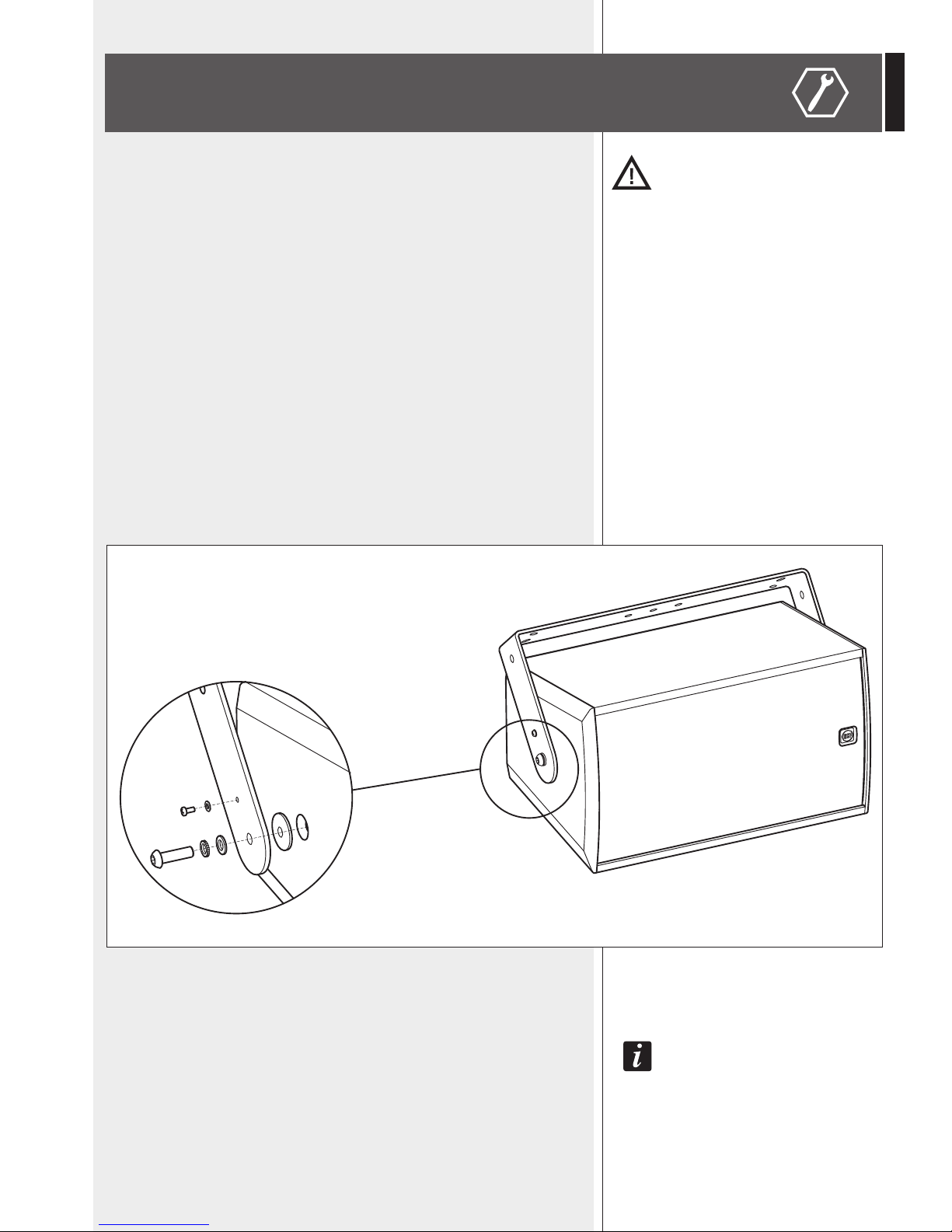
a) HORIZONTAL MOUNTING WITH U BRACKET
Necessary optional accessory:
- AC M501 H-BR (for the M 501 model)
- AC M601 H-BR (for the M 601 model)
- AC M801 H-BR (for the M 801 model)
- AC M502 H-BR (for the M 502 model)
- AC M602 H-BR (for the M 602 model).
Fix the U bracket to the wall / ceiling through at least 4 lateral wall plugs (max. M8) plus
a central one (max. M10).
Mount the U bracket to the loudspeaker by tightening the two M10x35 bolts into the holes
of the loudspeaker top and bottom, as shown in the figure below.
Before tightening the two M10 bolts, adjust the loudspeaker vertical tilt and then fix it
through two M4.2x22 self-threading screws (passing through the small hole of the U
bracket) directly into the loudspeaker cabinet wood.
Note: do Not tilt the loudspeaker upwards!
iNstead of simple m10 bolts, it is possible to use the iNcluded kNobs (haviNg m10 bolts).
8
ENGLISH
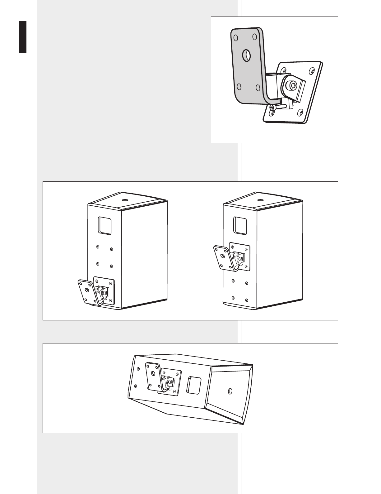
B) MOUNTING WITH A SWIVEL BRACKET
Necessary optional accessory: AC WM-M
Mount the fixed part of the AC WM-M accessory (shown in grey in the
respective figure) to the wall through its corners with four M10 wall plugs.
The central hole of the fixed part is useful to let pass the connecting cable
from the wall outlet.
It is possible to fix the moving part of the AC WM-M accessory directly to the loudspeaker
rear panel (in one of the possible positions), through four M6 flat head screws (as shown
in the figure below).
It is also possible the loudspeaker horizontal mounting (see the figure below).
Then, put the loudspeaker on the fixed part of the AC WM-M accessory (that is wallmounted) and tighten the bolt. The screw below allows vertical tilt adjustments.
AC WM-M
9
ENGLISH
WARNING: loudspeaker connections should be only made by qualified and experienced
personnel having the technical know-how or sufficient specific instructions (to ensure
that connections are made correctly) in order to prevent any electrical danger.
To prevent any risk of electric shock, do not connect loudspeakers when the amplifier is
switched on. Before turning the system on, check all connections and make sure there are
no accidental short circuits.
The entire sound system shall be designed and installed in compliance with the current
local laws and regulations regarding electrical systems.
‘Media’ series loudspeakers are designed for indoor use only. If installed outdoor,
loudspeakers shall be protected against water.
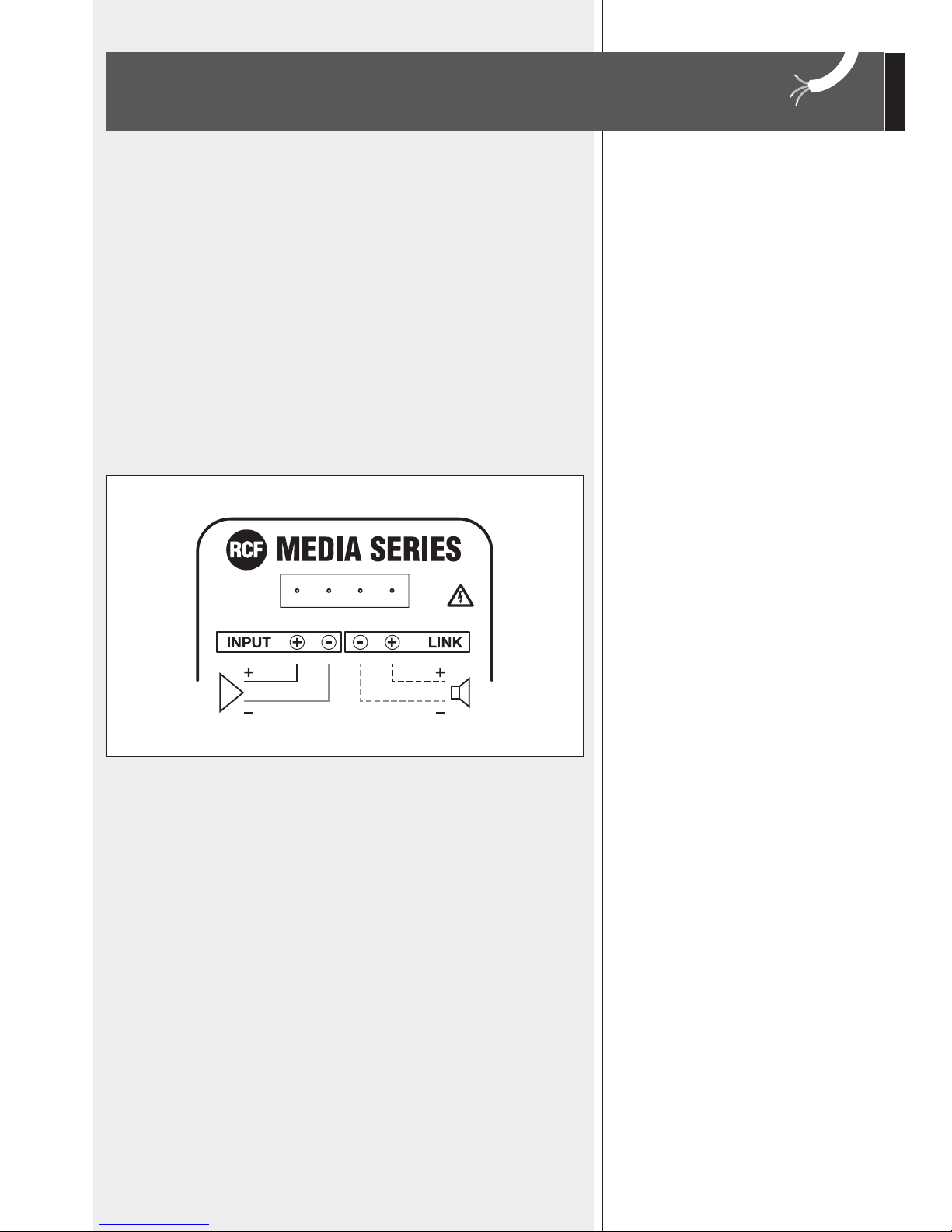
The impedance value of each loudspeaker is 8 Ω.
Connect the positive wire (amplifier ‘+’ output) to the pin ‘INPUT +’ of the 4-pin
EUROBLOCK connector. Connect the negative wire (amplifier ‘–’ output) to the pin
‘INPUT –’ of the 4-pin EUROBLOCK connector.
The ‘LINK +’ and ‘LINK –’ pins are useful to link another loudspeaker in parallel.
CONNECTIONS
10
ENGLISH
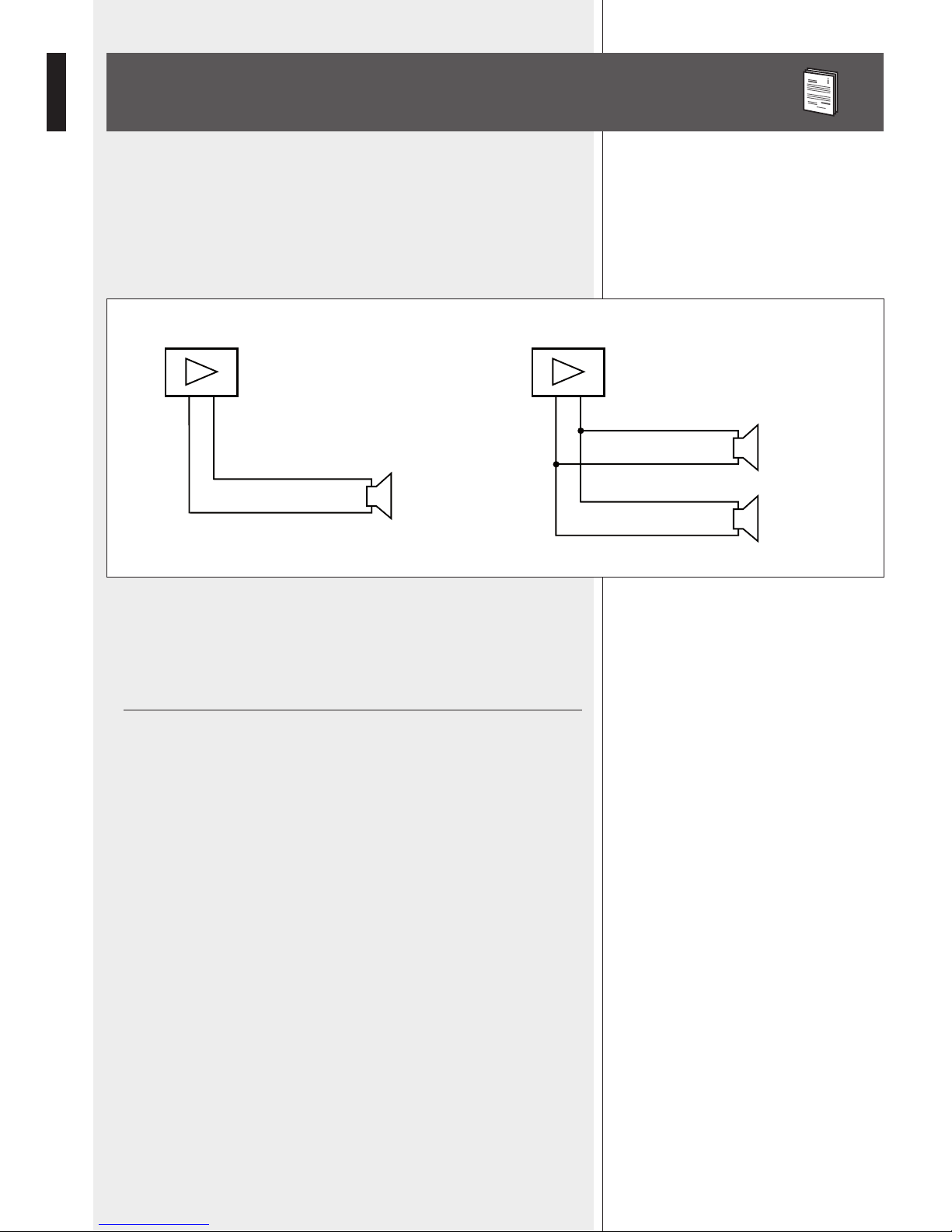
NOTES ABOUT LOW IMPEDANCE CONNECTIONS
- The total loudspeaker impedance must not be lower than the amplifier output
impedance. Note: a loudspeaker total impedance equal to the amplifier output one
permits to get the maximum deliverable power (but an higher loudspeaker impedance
entails less power).
- The total loudspeaker power shall be adequate for the maximum deliverable power of
the amplifier.
- The loudspeaker line shall be short (for long distances, it may be necessary to use cables
with large cross-section wires).
- Always use cables having wires with an adequate cross-section, considering the cable
length and the total loudspeaker power.
- Loudspeaker lines must be kept separated from the mains cables, microphone cables or
others, in order to avoid inductive phenomena may cause hum or noises.
- Use loudspeaker cables with twisted wires to reduce hum caused by inductive effects
due to coupling with electromagnetic fields.
- Do NOT connect the low impedance input directly to 70 / 100 V constant voltage lines.
- +
TOTAL IMPEDANCE: 4 Ω
8 Ω
8 Ω
+
+
- +
TOTAL IMPEDANCE: 8 Ω
8 Ω
+
 Loading...