

Page 1

USER MANUAL
MANUALE D’USO
PS 6048
- BACKUP POWER SUPPLY UNIT
AND BATTERY CHARGER
- ALIMENTATORE D’EMERGENZA
CARICABATTERIE
Page 2

Page 3

TABLE OF CONTENTS
INDICE
ENGLISH
SAFETY PRECAUTIONS
DESCRIPTION
INSTALLATION
INTERNAL JUMPER SETTING AND BATTERIES
BLOCK DIAGRAM
BATTERY WIRING INSTRUCTIONS
FRONT PANEL LEDS AND OPERATION
REAR PANEL AND WIRING
MAINTENANCE
TROUBLESHOOTING
SPECIFICATIONS
FUSES
ITALIANO
AVVERTENZE PER LA SICUREZZA
DESCRIZIONE
INSTALLAZIONE
IMPOSTAZIONE DEL JUMPER INTERNO E BATTERIE
SCHEMA A BLOCCHI
ISTRUZIONI PER IL CABLAGGIO DELLE BATTERIE
LED SUL PANNELLO FRONTALE E FUNZIONAMENTO
PANNELLO POSTERIORE E CABLAGGIO
MANUTENZIONE
RISOLUZIONE DEI PROBLEMI
DATI TECNICI
FUSIBILI
4
6
6
6
8
9
10
11
12
13
14
14
16
18
18
18
20
21
22
23
24
25
26
26
Page 4
4
ENGLISH
IMPORTANT
Before connecting and using this product, please read this instruction manual carefully
and keep it on hand for future reference.
The manual is to be considered an integral part of this product and must accompany it
when it changes ownership as a reference for correct installation and use as well as for
the safety precautions.
RCF S.p.A. will not assume any responsibility for the incorrect installation and / or use of
this product.
WARNING: To prevent the risk of re or electric shock, never expose this product to rain
or humidity.
SAFETY PRECAUTIONS
1. All the precautions, in particular the safety ones, must be read with special attention,
as they provide important information.
2.1 POWER SUPPLY FROM MAINS
- The mains voltage is sufciently high to involve a risk of electrocution: never install or
connect this product when its power cord is plugged in.
- Before powering up, make sure that all the connections have been made correctly and
the voltage of your mains corresponds to the voltage shown on the rating plate on the
unit, if not, please contact your RCF dealer.
- The metallic parts of the unit are earthed by means of the power cord.
- An apparatus with CLASS I construction shall be connected to a mains socket outlet
with a protective earthing connection.
- Protect the power cord from damage. Make sure it is positioned in a way that it cannot
be stepped on or crushed by objects.
- To prevent the risk of electric shock, never open this product: there are no parts inside
that the user needs to access.
- The mains plug is used as the disconnect device and it shall remain readily operable.
2.2 BATTERIES
- Operating voltage is 48 V dc (therefore, it is necessary to connect in series several
batteries having a lower nominal voltage, example: 4 x 12 V).
- Always use rechargeable batteries, which need to be chosen according to the maximum
possible load.
- Verify the polarity of batteries is correct.
- Do NOT short-circuit batteries (i.e. connecting the 2 opposite poles together with
metallic wires).
- Throw empty batteries away according to your country laws about ecology and
environment protection.
3. Make sure that no objects or liquids can get into this product, as this may cause a
short circuit.
This apparatus shall not be exposed to dripping or splashing.
No objects lled with liquid (such as vases) and no naked sources (such as lighted
candles) shall be placed on this apparatus.
IMPORTANT
SAFETY PRECAUTIONS
Page 5

5
ENGLISH
4. Never attempt to carry out any operations, modifications or repairs that are not
expressly described in this manual.
Contact your authorized service centre or qualified personnel should any of the
following occur:
- The product does not function (or functions in an anomalous way).
- The power cord has been damaged.
- Objects or liquids have got in the unit.
- The product has been subject to a heavy impact.
5. If this product is not used for a long period, disconnect both the power cord and
batteries.
6. If this product begins emitting any strange odours or smoke, switch it off immediately
and disconnect both the power cord and batteries.
7. Do not connect this product to any equipment or accessories not foreseen.
For suspended installation, only use the dedicated anchoring points and do not try to
hang this product by using elements that are unsuitable or not specic for this purpose.
Also check the suitability of the support surface to which the product is anchored (wall,
ceiling, structure, etc.), and the components used for attachment (screw anchors, screws,
brackets not supplied by RCF etc.), which must guarantee the security of the system /
installation over time, also considering, for example, the mechanical vibrations normally
generated by transducers.
To prevent the risk of falling equipment, do not stack multiple units of this product unless
this possibility is specied in the user manual.
8. RCF S.p.A. strongly recommends this product is only installed by professional qualied
installers (or specialised rms) who can ensure correct installation and certify it according
to the regulations in force.
The entire audio system must comply with the current standards and regulations
regarding electrical systems.
9. Supports and trolleys
The equipment should be only used on trolleys or supports, where necessary, that are
recommended by the manufacturer. The equipment / support / trolley assembly must be
moved with extreme caution. Sudden stops, excessive pushing force and uneven oors
may cause the assembly to overturn.
10. Do not obstruct the ventilation grilles of the unit. Situate this product far from any
heat sources and always ensure adequate air circulation around the ventilation grilles.
11. Do not use solvents, alcohol, benzene or other volatile substances for cleaning the
external parts of this product. Use a dry cloth.
Page 6

6
ENGLISH
INTERNAL JUMPER SETTING AND BATTERIES
I max a = I n - —
C
20
RCF S.P.A. THANKS YOU FOR PURCHASING THIS PRODUCT, WHICH HAS BEEN
DESIGNED TO GUARANTEE RELIABILITY AND HIGH PERFORMANCES.
DESCRIPTION
PS 6048 is a backup power supply unit suitable to get continuity power supply for EN 5416 system units (e.g. DXT 9000 and DXT 7000EN systems).
PS 6048 needs to be equipped with lead-acid batteries and includes recharging and
monitoring functions.
INSTALLATION
Fix the unit to a 19” rack cabinet through 4 screws.
According to EN 54-16 standard, the backup power supply unit shall be installed into the
same rack cabinet where there is the audio system with emergency purposes (or a system
part) to which it is connected.
IMPORTANTE: INTERNAl juMPER sETTINg shAll bE cARRIEd OuT ONly by EIThER RcF OR AN AuThORIsEd
sERvIcE cENTRE.
In normal operating mode: the PS 6048 recharges batteries (and maintains them when
they are fully charged).
The maximum total output current that can be supplied continuously (I max a) while
charging batteries is given by:
I n: nominal output current (12 A)
C: battery capacity [A h]
19” rack - 2U
Page 7
7
ENGLISH
I max b = I n
I max c = 150 A / 100 A
When the mains supply is available, the maximum total output current that can be
supplied for a short period of time (I max b) corresponds to the nominal value (12 A).
During this time, batteries are not charged (nor discharged).
When the mains supply is NOT available (backup operating mode), the maximum total
output current that can be supplied from batteries (I max c) is either 150 A if the internal
jumper is set to ‘75’ or 100 A if set to ‘50’.
a) I max c = 150 A
Set the internal jumper to ‘75’ and use batteries with a capacity of 86 to 225 Ah.
b) I max c = 100 A
Set the internal jumper to ‘50’ and use batteries with a capacity of 65 to 225 Ah.
The jumper factory setting is the ‘75’ position. Any other jumper setting is like the ‘50’
position.
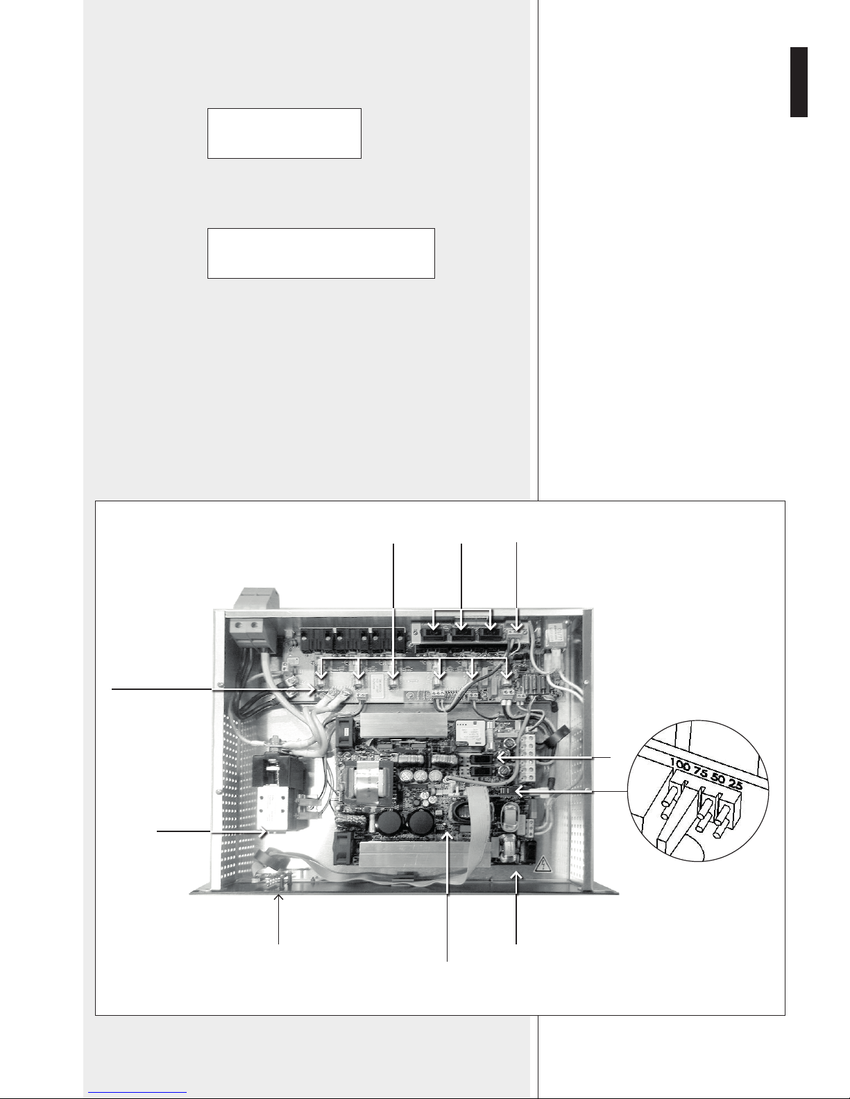
F1
F8
JUMPER
LEDs
RELAYS
F1
TO
F6 FAUX
1, 2, 3
POWER AND CONTROL
BOARD
AUXILIARY
OUTPUTS BOARD
MAIN OUTPUTS
BOARD
Page 8
8
ENGLISH
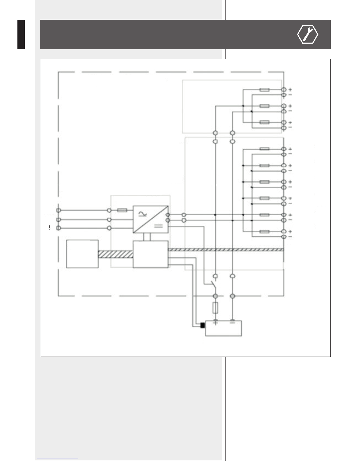
BLOCK DIAGRAM
OUTPUT 9
FAUX 3
F6
F5
F4
F3
F2
F1
F1
L
N
FAUX 2
FAUX 1
OUTPUT 8
OUTPUT 7
OUTPUT 6
OUTPUT 5
OUTPUT 4
OUTPUT 3
OUTPUT 2
OUTPUT 1
FAULT
INDICATIONS
(GPO)
POWER AND CONTROL BOARD
TEMPERATURE
SENSOR
BATTERIES
MAIN OUTPUT BOARD
AUXILIARY
OUTPUT BOARD
DAUGHTER
BOARD
LEDS
Page 9

9
ENGLISH
BATTERY WIRING INSTRUCTIONS
APPROVED BATTERY MODELS:
- Yuasa NPL series
- Powersonic GB series
- ABT TM series
- Enersys VE series
- Effekta BTL series
- Long GB series.
It is advised to secure batteries with a (low resistance, gG curve) fuse, chosen according
to maximum current.
The battery temperature sensor shall be placed as close as possible to batteries, but it
does not need to be in contact with them. For example, it may be xed on the battery
cables.
The PS 6640 checks the battery resistance (including connections) every 4 hours.
The fault threshold resistance value is either 32 mΩ ±10% if the jumper is set to the ‘75’
position or 48 mΩ ±10% if set to the ‘50’ position. Exceeding this threshold is signaled
as a battery fault: batteries will not have the required backup duration in case of mains
power cut.
To avoid possible false fault indications, use battery cables as short as possible and with
large cross sections (35 mm² max).
Approximately, the resistance per metre of a cable (with two copper wires) is:
- 3.6 mΩ/m (10 mm² section)
- 2.3 mΩ/m (16 mm² section)
- 1.5 mΩ/m (25 mm² section)
- 1.1 mΩ/m (35 mm² section).
ExAMPlE: ThE REsIsTANcE vAluE OF A 1.5 M cAblE wITh A 10 MM² cROss-sEcTION Is 5.4 MΩ.
1.5M cAblEs wITh A 25 MM² cROss-sEcTION AllOw cORREcT OPERATION wITh All REcOMMENdEd bATTERIEs.
ThE bATTERy FusE Adds AbOuT 1 TO 2 MΩ. ThE cONNEcTIONs ANd cRIMPINg shOuld bE REAlIzEd PROPERly IN
ORdER TO gET ThE lOwEsT REsIsTANcE As POssIblE.
Page 10

10
ENGLISH
FRONT PANEL LEDS AND OPERATION
The MAINS FAULT1 is indicated when the front panel LED turns from green to yellow
and remotely by its respective (5 s) delayed dry contact (fail-safe, for remote monitoring)
when:
- The mains is not present or lower than either 185 V ac ±5% (if the charger is not
recharging) or 165 V ac ±5% (if the charger is recharging).
- The mains fuse is blown or not present.
- The charger is faulty.
- The internal temperature is too high.
Green LED: OK (no mains fault).
The BATTERY FAULT
2
is indicated when the front panel LED turns from green to
yellow and remotely by its respective dry contact (fail-safe, for remote monitoring) when:
- Batteries are not present (the battery test is carried out in this way: every 30 seconds
for the rst 20 minutes after commissioning and then every 15 minutes; if a fault is
detected, batteries will have been tested every 30 seconds for 20 minutes after the fault
disappears).
- The battery internal resistance is too high (a test occurs every 4 hours when the mains
supply is present and the charger output current is lower than 12A; the resistance limit
value is 32 mΩ ±10%).
- The battery voltage is lower than 47 V ±3% (when the mains supply is present).
A voltage compensation system maintains the charge characteristics within the battery
limits across the entire operational temperature range.
ThE bATTERy lOw vOlTAgE PROTEcTION ThREshOld Is 43.2 v ±3 %. whEN ThE bATTERy vOlTAgE REAchEs
ThE PROTEcTION ThREshOld, A RElAy dIscONNEcTs bATTERIEs FROM MAIN ANd AuxIlIARy OuTPuTs.
Protection from battery reverse connection:
- At start-up, the battery relay will not let the current pass.
- During operation: the F8 fuse will blow out.
If the battery voltage is either higher than 60 V ±3% or lower than 40 V ±3%, batteries
will not be connected.
Green LED: OK (no battery fault).
The OUTPUT VOLTAGE FAULT
3
is indicated when the front panel LED turns
from green to yellow and remotely by its respective dry contact (fail-safe, for remote
monitoring) if there is no output voltage on one or more outputs (all nine outputs are
checked).
Green LED: OK (no output voltage fault).
1
2
3
Page 11

11
ENGLISH
REAR PANEL AND WIRING
4
Six (1 to 6) main 48 V dc outputs (to ampliers).
Connectors: lockable screw terminals (max. wire section: 16 mm²).
5
Three (7, 8, 9) auxiliary 48 V dc outputs.
Connectors: screw terminals (max. wire section: 2.5 mm²).
6
Logic outputs for remote fault monitoring.
From left to right:
MAINS FAULT, BATTERY FAULT, OUTPUT VOLTAGE FAULT.
Connectors: screw terminals (max. wire section: 1.5 mm²).
Each logic output has three dry contacts: normally closed (NC), common and normally
open (NO).
Fault indications can be obtained by connecting these contacts to logic inputs of the
control device.
The max. current is either 1 A at 24 V dc or 0.5 A at 120 V ac.
7
Input for the mains power cord plug (lockable, IEC320, 2.5mm² wire section).
8
Input for the battery temperature sensor.
9
48 V dc input (for battery connection).
Connector: screw terminals (max. wire section: 50 mm²).
Four 12 V batteries need to be linked in series (total voltage: 48 V dc).
4
4 5
8
9
6
6
7
8
9
7
5
Page 12

12
ENGLISH
DIODE INSERTION TO LINK MU 7100EN (DXT 7000EN)
+
44 ÷ 50 V dc
4 V
down
diodes
48 ÷ 54 V dc
–
The MU 7100EN (DXT 7000EN main unit) 48VDC input shall be connected to a PS 6048
through diodes that are needed to get a 4 V voltage drop.
In order to ensure maximal and durable service, this product needs to be installed in a dry
and ventilated location and maintained clean. RCF S.p.A. is in no case liable for damages
associated with improper use or incorrect maintenance of the equipment.
WARNING: do NOT use an incorrect type of batteries, as this may result in an explosion
hazard.
Used batteries must be disposed of in compliance with recycling requirements.
a. Connect the battery cable to the PS 6048 48 V dc input
9
, but do NOT connect the
battery terminals.
b. After connecting the mains power cord and all loads, turn on the mains supply (switch
on the circuit-breaker upstream).
c. Check the output voltage to loads.
d. Connect the battery terminals.
The PS 6048 properly operates when all its three front panel LEDs are lit and green.
IMPORTANT: IF AMPlIFIERs ARE NOT POwEREd by ThE sAME MAINs lINkEd TO ThE Ps 6048, AN AMPlIFIER
MAINs FAIluRE MusT gENERATE AN AlARM TO ThE vOIcE AlARM sysTEM.
MAINTENANCE
LT 7208
WIRING
Page 13

13
ENGLISH
NO OUTPUT VOLTAGE:
- Check the mains supply presence
- Check fuses (RCF service only)
- Check each single output voltage
- Check that each 12 V dc battery has a voltage equal or higher than 11.5 V dc
- Repeat measurements after having disconnected loads and batteries
- Check the front panel LED indications
- If all the previous steps are validated, check the load compatibility
THE BATTERY FAULT LED IS LIT YELLOW:
- Check if the battery voltage is in the 40 ÷ 60 V range
- Check the battery wiring and polarity
BATTERIES DO NOT TAKE OVER AFTER A MAINS FAULT:
- Check the voltage of each single battery
- Check the battery link and fuse
- Check the voltage on each single output
IF THE FRONT PANEL LED ARE NOT LIT:
- Check the mains supply presence
- Check the battery link and fuse
- Check the voltage on each single output
- Check the internal at cable (RCF service only)
TROUBLESHOOTING
Page 14

14
ENGLISH
FUSES
SPECIFICATIONS
RATED OUTPUT VOLTAGE:
OUTPUT VOLTAGE AT HALF LOAD (25°C):
MAX. TOTAL POWER (ALL THE 9 OUTPUTS):
MAX. TOTAL OUTPUT CURRENT (ALL THE 9 OUTPUTS):
MAIN 48 V DC OUTPUTS (TO AMPLIFIERS):
MAX. POWER PER EACH MAIN OUTPUT:
MAX. CURRENT PER EACH MAIN OUTPUT:
AUXILIARY 48 V DC OUTPUTS:
MAX. POWER PER EACH AUXILIARY OUTPUT:
MAX. CURRENT PER EACH AUXILIARY OUTPUT:
CHARGER RATED OUTPUT CURRENT:
OPERATING TEMPERATURE:
OPERATING RELATIVE HUMIDITY:
INTERNAL TEMPERATURE, PROTECTION THRESHOLD:
STORAGE TEMPERATURE:
OPERATING VOLTAGE (FROM MAINS):
MAXIMUM PRIMARY CURRENT (@ 195 V):
POWER CONSUMPTION (AT FULL LOAD):
BATTERY VOLTAGE:
AUTHORIZED BATTERY CAPACITY:
DIMENSIONS:
NET WEIGHT:
CPR:
STANDARD REFERENCE:
MOTHER BOARD F1 (MAINS):
MOTHER BOARD F8:
MAIN OUTPUT BOARD F1 TO F6 (6 OUTPUTS):
AUXILIARY OUTPUT BOARD FAUX1-2-3 (3 OUTPUTS):
EXTERNAL BATTERY FUSE (NOT INCLUDED):
48 V dc
54.4 V dc ±0.5%
7200 W (internal jumper set to ‘75’)
4800 W (internal jumper set to ‘50’)
150 A (internal jumper set to ‘75’)
100 A (internal jumper set to ‘50’)
6 (from 1 to 6)
1536 W
32 A
3 (from 7 to 9)
240 W
5 A
12 A
–5 ÷ +45 °C (23 ÷ 113 °F) at 12 A
20 ÷ 95 % without condensation
+65°C (149 °F)
–25 ÷ +85 °C (–13 ÷ +185 °F)
230 V ac ±15% (47 ÷ 63 Hz), class I
4 A
760 W
48 V dc (four 12 V batteries linked in series)
86 ÷ 225 Ah (internal jumper set to ‘75’)
65 ÷ 225 Ah (internal jumper set to ‘50’)
19”, 2U rack
344 mm deep without connectors
399 mm deep with connectors
5.9 kg (13 lbs)
0333-CPR-075383-2, 2011
EN 54-4 (1997) + A1 (2002) + A2 (2006)
T8A 5x20 250V (breaking capacity: 1500 A)
T12.5A 5x20
32 A gG 10x38
F5A 5x20
choose a gG curve fuse according to the battery maximum
current (e.g. 80/100/125 A)
Page 15

15
ITALIANO
INDICE
AVVERTENZE PER LA SICUREZZA
DESCRIZIONE
INSTALLAZIONE
IMPOSTAZIONE DEL JUMPER INTERNO E BATTERIE
SCHEMA A BLOCCHI
ISTRUZIONI PER IL CABLAGGIO DELLE BATTERIE
LED SUL PANNELLO FRONTALE E FUNZIONAMENTO
PANNELLO POSTERIORE E CABLAGGIO
MANUTENZIONE
RISOLUZIONE DEI PROBLEMI
DATI TECNICI
FUSIBILI
16
18
18
18
20
21
22
23
24
25
26
26
Page 16

16
ITALIANO
IMPORTANTE
Prima di collegare ed utilizzare questo prodotto, leggere attentamente le istruzioni
contenute in questo manuale, il quale è da conservare per riferimenti futuri.
Il presente manuale costituisce parte integrante del prodotto e deve accompagnare
quest’ultimo anche nei passaggi di proprietà, per permettere al nuovo proprietario di
conoscere le modalità d’installazione e d’utilizzo e le avvertenze per la sicurezza.
L’installazione e l’utilizzo errati del prodotto esimono la RCF S.p.A. da ogni responsabilità.
ATTENZIONE: per prevenire i rischi di amme o scosse elettriche, non esporre mai
questo prodotto alla pioggia o all’umidità.
AVVERTENZE PER LA SICUREZZA
1. Tutte le avvertenze, in particolare quelle relative alla sicurezza, devono essere lette con
particolare attenzione, in quanto contengono importanti informazioni.
2.1 ALIMENTAZIONE DA RETE ELETTRICA
- La tensione di alimentazione dell’apparecchio ha un valore sufcientemente alto da
costituire un rischio di folgorazione per le persone: non procedere mai all’installazione
od alla connessione dell’apparecchio con il cavo dell’alimentazione collegato alla rete
elettrica.
- Prima di alimentare questo prodotto, assicurarsi che tutte le connessioni siano corrette
e che la tensione della vostra rete di alimentazione corrisponda quella di targa
dell’apparecchio, in caso contrario rivolgetevi ad un rivenditore RCF.
- Le parti metalliche dell’apparecchio sono messe a terra tramite il cavo di alimentazione.
Un apparecchio avente costruzione di CLASSE I deve essere connesso alla presa di rete
con un collegamento al conduttore di protezione (terra).
- Accertarsi che il cavo di alimentazione dell’apparecchio non possa essere calpestato o
schiacciato da oggetti, al ne di salvaguardarne la perfetta integrità.
- Per evitare il rischio di shock elettrici, non aprire mai l’apparecchio: all’interno non vi
sono parti che possono essere utilizzate dall’utente.
- La spina del cavo d’alimentazione è utilizzata come dispositivo di scollegamento e deve
rimanere sempre facilmente accessibile.
2.2 BATTERIE
- La tensione nominale è 48 V c.c. (pertanto, occorre collegare in serie più batterie aventi
una tensione nominale inferiore, es. 4 x 12 V).
- Utilizzare sempre batterie ricaricabili, opportunamente scelte in funzione del massimo
carico possibile.
- Vericare che sia rispettata la polarità delle batterie.
- Non cortocircuitare le batterie (ad esempio collegando i 2 poli opposti con un lo di
metallo).
- Smaltire le batterie esaurite facendo riferimento alle norme di legge vigenti (nel paese
di utilizzo) in materia di ecologia e protezione dell’ambiente.
3. Impedire che oggetti o liquidi entrino all’interno del prodotto, perché potrebbero
causare un corto circuito. L’apparecchio non deve essere esposto a stillicidio o a spruzzi
d’acqua; nessun oggetto pieno di liquido (quali vasi) e nessuna sorgente di amma nuda
(es. candele accese) deve essere posto sull’apparecchio.
IMPORTANTE
AVVERTENZE PER LA SICUREZZA
Page 17

17
ITALIANO
4. Non eseguire sul prodotto interventi / modiche / riparazioni se non quelle
espressamente descritte sul manuale istruzioni. Contattare centri di assistenza autorizzati
o personale altamente qualicato quando:
- l’apparecchio non funziona (o funziona in modo anomalo);
- il cavo di alimentazione è danneggiato;
- oggetti o liquidi sono entrati nell’apparecchio;
- l’apparecchio ha subito forti urti.
5. Qualora questo prodotto non sia utilizzato per lunghi periodi, scollegare il cavo
d’alimentazione dalla rete e le batterie.
6. Nel caso che dal prodotto provengano odori anomali o fumo, spegnerlo
immediatamente e scollegare il cavo d’alimentazione e le batterie.
7. Non collegare a questo prodotto altri apparecchi e accessori non previsti.
Quando è prevista l’installazione sospesa, utilizzare solamente gli appositi punti di
ancoraggio e non cercare di appendere questo prodotto tramite elementi non idonei o
previsti allo scopo.
Vericare inoltre l’idoneità del supporto (parete, softto, struttura ecc., al quale è
ancorato il prodotto) e dei componenti utilizzati per il ssaggio (tasselli, viti, staffe non
fornite da RCF ecc.) che devono garantire la sicurezza dell’impianto / installazione nel
tempo, anche considerando, ad esempio, vibrazioni meccaniche normalmente generate da
un trasduttore.
Per evitare il pericolo di cadute, non sovrapporre fra loro più unità di questo prodotto,
quando questa possibilità non è espressamente contemplata dal manuale istruzioni.
8. La RCF S.p.A. raccomanda vivamente che l’installazione di questo prodotto sia
eseguita solamente da installatori professionali qualicati (oppure da ditte specializzate)
in grado di farla correttamente e certicarla in accordo con le normative vigenti. Tutto
il sistema audio dovrà essere in conformità con le norme e le leggi vigenti in materia di
impianti elettrici.
9. Sostegni e Carrelli
Se previsto, il prodotto va utilizzato solo su carrelli o sostegni consigliati dal produttore.
L’insieme apparecchio-sostegno / carrello va mosso con estrema cura. Arresti improvvisi,
spinte eccessive e superci irregolari o inclinate possono provocare il ribaltamento
dell’assieme.
10. Non ostruire le griglie di ventilazione dell’unità. Collocare il prodotto lontano da fonti
di calore e garantire la circolazione dell’aria in corrispondenza delle griglie di aerazione.
11. Non usare solventi, alcool, benzina o altre sostanze volatili per la pulitura delle parti
esterne dell’unità; usare un panno asciutto.
Page 18

18
ITALIANO
IMPOSTAZIONE DEL JUMPER INTERNO E BATTERIE
I max a = I n - —
C
20
RCF S.P.A. VI RINGRAZIA PER L’ACQUISTO DI QUESTO PRODOTTO, REALIZZATO
IN MODO DA GARANTIRNE L’AFFIDABILITÀ E PRESTAZIONI ELEVATE.
DESCRIZIONE
PS 6048 è un alimentatore che assicura la continuità dell’alimentazione nei sistemi audio
con funzioni d’emergenza in accordo con la norma EN 54-16 (es. per i sistemi DXT 9000
e DXT 7000EN); deve essere implementato di batterie ed include le funzioni di ricarica e
controllo.
INSTALLAZIONE
Fissare l’unità al rack 19” tramite 4 viti.
In accordo con la norma EN 54-16, l’alimentatore d’emergenza deve essere installato
nello stesso rack dove è presente il sistema audio con funzioni d’emergenza (od una sua
sezione) a cui è collegato.
IMPORTANTE: l'IMPOsTAzIONE dEl juMPER INTERNO dEvE EssERE EFFETTuATA sOlO dA RcF OPPuRE dA uN
cENTRO AssIsTENzA AuTORIzzATO.
Durante il funzionamento normale, l'alimentatore PS 6048 ricarica le batterie e le
mantiene cariche.
La corrente massima erogabile continuamente (I max a) durante la ricarica delle batterie
e data da:
I n: corrente nominale d'uscita (12 A)
C: capacità delle batterie [A h]
RACK 19” - 2U
Page 19

19
ITALIANO
I max b = I n
I max c = 150 A / 100 A
Quando l'alimentazione da rete elettrica è disponibile, la corrente massima erogabile per
un breve tempo (I max b) corrisponde al valore nominale (12 A).
Durante questo tempo, le batterie non sono ricaricate (e non si scaricano).
Quando l'alimentazione da rete elettrica NON è disponibile, la corrente massima
erogabile dalle batterie (I max c) è 150 A se il jumper interno è impostato su “75”
o 100 A se impostato su “50”.
a) I max c = 150 A
Impostare il jumper interno su “75” ed usare batterie con capacità compresa tra 86 e
225 Ah.
b) I max c = 100 A
Impostare il jumper interno su “50” ed usare batterie con capacità compresa tra 65 e
225 Ah.
L'impostazione di fabbrica del jumper è la posizione “75”.
Ogni altra impostazione è equivalente alla posizione “50”.
F8
JUMPER
F1LED
RELÈ
DA F1 a F6
SCHEDA DI
ALIMENTAZIONE E
CONTROLLO
SCHEDA DELLE USCITE AUSILIARI
SCHEDA DELLE
USCITE PRINCIPALI
FAUX
1, 2, 3
Page 20

20
ITALIANO
SCHEMA A BLOCCHI
USCITA 9
FAUX 3
F6
F5
F4
F3
F2
F1
F1
L
N
FAUX 2
FAUX 1
USCITA 8
USCITA 7
USCITA 6
USCITA 5
USCITA 4
USCITA 3
USCITA 2
USCITA 1
SEGNALAZIONE
GUASTI
(uscite logiche)
SCHEDA DI ALIMENTAZIONE E
CONTROLLO
SENSORE
DI TEMPERATURA
BATTERIE
SCHEDA DELLE USCITE
PRINCIPALI
SCHEDA DELLE USCITE
AUSILIARI
SCHEDA
FIGLIA
LEDS
Page 21

21
ITALIANO
ISTRUZIONI PER IL CABLAGGIO DELLE BATTERIE
MODELLI APPROVATI DI BATTERIE:
- Yuasa serie NPL;
- Powersonic serie GB;
- ABT serie TM;
- Enersys serie VE;
- Effekta serie BTL;
- Long serie GB.
È consigliabile proteggere le batterie con un fusibile (a bassa resistenza, di tipo “gG")
scelto considerando la massima intensità di corrente.
Il sensore di temperatura delle batterie deve essere posizionato il più vicino possibile alla
batterie, ma non è necessario che sia in contatto con queste; ad esempio, potrebbe essere
ssato al cavo.
L'alimentatore PS 6640 verica la resistenza delle batterie (incluse le connessioni) ogni 4
ore.
Il valore di resistenza usato come soglia di guasto è 32 mΩ ±10% (se il jumper è
impostato nella posizione “75”) o 48 mΩ ±10% (jumper su “50”); sopra questa soglia si
ha la segnalazione di guasto, in quanto le batterie non hanno più la durata richiesta nel
caso che manchi l'alimentazione da rete elettrica.
Per evitare possibili indicazioni false di guasti, usare cavi per batterie i più corti possibile e
con sezioni elevate (max. 35 mm²).
Approssivativamente, la resistenza per metro di cavo (con 2 li di rame) è:
- 3,6 mΩ/m (sezione 10 mm²);
- 2,3 mΩ/m (sezione 16 mm²);
- 1,5 mΩ/m (sezione 25 mm²);
- 1,1 mΩ/m (sezione 35 mm²).
EsEMPIO: Il vAlORE dI REsIsTENzA dI uN cAvO luNgO 1,5 M E dI sEzIONE 10 MM² è 5,4 MΩ.
dATE lE bATTERIE RAccOMANdATE, è cONsIglIAbIlE l'usO dI uN cAvO luNgO 1,5 M E dI sEzIONE 25 MM².
Il FusIbIlE dEllE bATTERIE AggIuNgE cIRcA 1÷2 MΩ. Il cOllEgAMENTO E lA cRIMPATuRA dOvREbbERO EssERE
REAlIzzATI cORRETTAMENTE PER OTTENERE lA MINIMA REsIsTENzA POssIbIlE.
Page 22

22
ITALIANO
LED SUL PANNELLO FRONTALE E FUNZIONAMENTO
Il LED MAINS FAULT 1, quando è acceso giallo, indica un problema all'alimentazione
da rete elettrica, segnalato anche dal rispettivo contatto “pulito” (ritardato di 5 s) sul
pannello posteriore.
Si ha quando:
- la tensione di rete è inferiore a 185 V ac ±5% (se il caricabatterie non sta ricaricando)
oppure 165 V ac ±5% (se il caricabatterie sta ricaricando) oppure è totalmente assente;
- il fusibile di protezione F1 sulla scheda madre è bruciato (o assente);
- il caricabatterie è guasto;
- la temperatura interna è troppo alta.
LED acceso verde: nessun guasto (funzionamento corretto).
Il LED BATTERY FAULT
2
, se acceso giallo, indica un problema alle batterie, segnalato
anche dal rispettivo contatto “pulito” sul pannello posteriore.
Si ha quando:
- le batterie non sono presenti (il test è effettuato nel seguente modo: ogni 30 secondi
per i primi 20 minuti dopo l'avviamento e successivamente ogni quarto d'ora; se
sarà rilevato un guasto, il test sarà effettuato ogni 30 secondi per 20 minuti dopo la
scomparsa del problema);
- la resistenza interna delle batterie è troppo alta (è effettuato un test ogni 4 ore quando
l'alimentazione da rete elettrica è presente e la corrente d'uscita dal caricabatterie è
inferiore a 12A; il valore limite della resistenza è 32 mΩ ±10%);
- la tensione delle batterie è inferiore a 47 V ±3% (quando l'alimentazione da rete è
presente).
Un sistema di compensazione della tensione mantiene le caratteristiche di carica entro i
limiti delle batterie (e nel campo della temperatura di funzionamento).
lA sOglIA dI PROTEzIONE dEllE bATTERIE PER TENsIONE TROPPO bAssA è 43,2 v ±3 %.
QuANdO lA TENsIONE dEllE bATTERIE RAggIuNgE lA sOglIA dI PROTEzIONE, uN RElè INTERROMPE lA
cONNEssIONE TRA lE bATTERIE E TuTTE lE uscITE (PRINcIPAlI Ed AusIlIARIE).
Protezione da collegamento inverso (polarità invertite) delle batterie:
- se all'accensione, il relè in serie alle batterie interrompe il collegamento;
- se durante il funzionamento, brucia il fusibile F8.
Se la tensione delle batterie è superiore a 60 V ±3% od inferiore a 40 V ±3%, il
collegameno delle batterie è interrotto.
LED acceso verde: nessun guasto (funzionamento corretto).
Il LED OUTPUT VOLTAGE FAULT
3
, se acceso giallo, indica l'assenza di tensione su
una o più uscite (nota: tutte le nove uscite sono controllate), problema segnalato anche
dal rispettivo contatto “pulito” sul pannello posteriore.
LED acceso verde: nessun guasto (funzionamento corretto).
1
2
3
Page 23

23
ITALIANO
PANNELLO POSTERIORE E CABLAGGIO
4
Sei (da 1 a 6) uscite principali 48 V c.c. (per amplicatori).
Connettori: terminali a vite bloccabili (max. sezione conduttori: 16 mm²).
5
Tre (7, 8, 9) uscite ausiliarie 48 V c.c. .
Connettori: terminali a vite (max. sezione conduttori: 2.5 mm²).
6
Uscite logiche per segnalazione remota di guasti.
Da sinistra a destra:
MAINS FAULT (guasto alimentazione rete elettrica), BATTERY
FAULT (guasto batterie), OUTPUT VOLTAGE FAULT (guasto
uscite).
Connettori: terminali a vite (max. sezione conduttori: 1.5 mm²).
Ciascuna uscita logica ha tre tre contatti “puliti”: normalmente chiuso (NC), comune
e normalmente aperto (NO). Le indicazioni di guasto si ottengono collegando questi
contatti ad ingressi logici di dispositivi di controllo.
La massima corrente applicabile ai contatti è 1 A a 24 V c.c. oppure 0,5 A a 120 V c.a. .
7
Ingresso per il cavo d'alimentazione da rete elettrica (bloccabile, IEC320, sezione dei
conduttori: 2,5 mm²).
8
Ingresso per il sensore di temperatura delle batterie.
9
Ingresso 48 V c.c. per il collegamento delle batterie.
Connettori: terminali a vite (max. sezione conduttori: 50 mm²).
Quattro batterie da 12 V devono essere collegate in serie (tensione totale: 48 V dc).
4
4 5
8
9
6
6
7
8
9
7
5
Page 24

24
ITALIANO
UTILIZZO DI DIODI PER IL COLLEGAMENTO CON MU 7100EN (DXT 7000EN)
+
44 ÷ 50 V dc
diodi
caduta
4 V
48 ÷ 54 V dc
–
Per collegare l'ingresso 48VDC dell'unità centrale MU 7100EN (del sistema DXT 7000EN),
è necessario inserire dei diodi in modo da ottenere una caduta di tensione di circa 4 V.
Al ne di garantire la sua miglior funzionalità ed afdabilità, il prodotto deve essere
installato in un luogo asciutto e ventilato e mantenuto pulito. RCF S.p.A. non è in alcun
caso responsabile per i danni connessi con l’uso improprio o errata manutenzione.
ATTENZIONE: NON usare batterie non adatte, in quanto ciò potrebbe causare un rischio
di esplosione.
Le batterie usate devono essere smaltite in conformità con le norme vigenti.
a. Collegare il cavo delle batterie all’ingresso 48 V c.c.
9
del PS 6048, ma NON
collegarlo ad i terminali delle batterie.
b. Dopo aver connesso il cavo dell’alimentazione da rete elettrica e tutti i carichi, mettere
la linea in tensione (accendere l’interruttore di rete a monte).
c. Vericare la tensione d’uscita verso i carichi.
d. Collegare i terminali delle batterie.
Il PS 6048 funziona correttamente quando i suoi tre LED sul pannello frontale sono tutti
accesi e verdi.
IMPORTANTE: sE glI AMPlIFIcATORI NON sONO AlIMENTATI dAllA sTEssA RETE ElETTRIcA cOllEgATA Al Ps
6048, uN EvENTuAlE guAsTO dI RETE dI uN AMPlIFIcATORE dEvE sEgNAlARE uN AllARME Al sIsTEMA AudIO
d’EvAcuAzIONE.
MANUTENZIONE
LT 7208
CABLAGGIO
Page 25

25
ITALIANO
NESSUNA TENSIONE DI USCITA:
- vericare la presenza dell'alimentazione da rete elettrica;
- controllare i fusibili (solo assistenza RCF);
- controllare la tensione di ciascuna singola uscita;
- vericare che ciascuna batteria da 12 V abbia una tensione uguale o superiore a 11,5 V;
- ripetere le misure dopo aver scollegato i carichi e le batterie;
- controllare le indicazioni dei LED sul pannello frontale;
- dopo aver effettuato tutti i controlli sopraelencati, vericare la compatibilità del carico.
IL LED BATTERY FAULT LED È ACCESO GIALLO:
- controllare se la tensione (totale) delle batterie è compresa nel campo 40 ÷ 60 V;
- vericare il cablaggio delle batterie (e la corretta polarità).
LE BATTERIE NON SI INSERISCONO QUANDO MANCA LA TENSIONE DI RETE:
- vericare la tensione di ogni singola batteria;
- controllare il collegamento delle batterie ed il rispettivo fusibile di protezione;
- controllare la tensione di ciascuna singola uscita.
I LED SUL PANNELLO FRONTALE NON SONO ACCESI:
- vericare la presenza dell'alimentazione da rete elettrica;
- controllare il collegamento delle batterie ed il rispettivo fusibile di protezione;
- controllare la tensione di ciascuna singola uscita;
- controllare il “at cable” interno (solo assistenza RCF).
RISOLUZIONE DEI PROBLEMI
Page 26

26
ITALIANO
FUSIBILI
DATI TECNICI
TENSIONE NOMINALE D’USCITA:
TENSIONE D’USCITA CON MEZZO CARICO (25°C):
MAX. POTENZA TOTALE (TUTTE LE 9 USCITE):
MAX. CORRENTE D’USCITA TOTALE (TUTTE LE 9 USCITE):
USCITE PRINCIPALI 48 V C.C. (PER AMPLIFICATORI):
MAX. POTENZA PER CIASCUNA USCITA PRINCIPALE:
MAX. CORRENTE PER CIASCUNA USCITA PRINCIPALE:
USCITE AUSILIARIE 48 V C.C.:
MAX. POTENZA PER CIASCUNA USCITA AUSILIARIA:
MAX. CORRENTE PER CIASCUNA USCITA AUSILIARIA:
CORRENTE D’USCITA NOMINALE DEL CARICABATTERIE:
TEMPERATURA DI FUNZIONAMENTO:
UMIDITÀ RELATIVA:
TEMPERATURA INTERNA, SOGLIA DI PROTEZIONE:
TEMPERATURA DI STOCCAGGIO:
TENSIONE DI FUNZIONAMENTO (DA RETE):
CORRENTE ASSORBITA (A 195 V):
CONSUMO (POTENZA A PIENO CARICO):
TENSIONE NOMINALE BATTERIE:
CAPACITÀ BATTERIE CONSENTITA:
DIMENSIONI:
PESO NETTO:
CPR:
NORMA DI REFERIMENTO:
SCHEDA MADRE F1 (ALIMENTAZIONE RETE):
SCHEDA MADRE F8:
SCHEDA USCITE PRINCIPALI F1÷F6 (6 USCITE):
SCHEDA USCITE AUSILIARIE FAUX1-2-3 (3 USCITE):
FUSIBILE ESTERNO PROTEZIONE BATTERIE (NON INCLUSO):
48 V c.c.
54,4 V c.c. ±0,5%
7200 W (jumper interno su “75”)
4800 W (jumper interno su “50”)
150 A (jumper interno su “75”)
100 A (jumper interno su “50”)
6 (da 1 a 6)
1536 W
32 A
3 (da 7 a 9)
240 W
5 A
12 A
–5 ÷ +45 °C (con I ricarica: 12 A)
20 ÷ 95 % senza condensa
+65°C
–25 ÷ +85 °C
230 V c.a. ±15% (47 ÷ 63 Hz), classe I
4 A
760 W
48 V c.c. (quattro batterie da 12 V in serie)
86 ÷ 225 Ah (jumper interno su “75”)
65 ÷ 225 Ah (jumper interno su “50”)
2 unità rack 19”
profondità senza connettori: 344 mm
profondità con connettori: 399 mm
5,9 kg
0333-CPR-075383-2, 2011
EN 54-4 (1997) + A1 (2002) + A2 (2006)
T8A 5x20 250V (potere di interruzione: 1500 A)
T12.5A 5x20
32 A gG 10x38
F5A 5x20
scegliere un fusibile con curva gG
secondo la corrente massima delle batterie
(es. 80/100/125 A)
Page 27

Page 28

10307389 revC
www.rcfaudio.com
HEADQUARTERS:
RCF S.p.A. Italy
tel. +39 0522 274 411
e-mail: info@rcf.it
RCF UK
tel. 0844 745 1234
Int. +44 870 626 3142
e-mail: info@rcfaudio.co.uk
RCF France
tel. +33 1 49 01 02 31
e-mail: france@rcf.it
RCF Germany
tel. +49 2203 925370
e-mail: germany@rcf.it
RCF Spain
tel. +34 91 817 42 66
e-mail: info@rcfaudio.es
RCF Belgium
tel. +32 (0) 3 - 3268104
e-mail: belgium@rcf.it
RCF USA Inc.
tel. +1 (603) 926-4604
e-mail: info@rcf-usa.com
Except possible errors and omissions.
RCF S.p.A. reserves the right to make modications without prior notice.
Salvo eventuali errori ed omissioni.
RCF S.p.A. si riserva il diritto di apportare modiche senza preavviso.
2015 / 03
Manufactured by SLAT – 180130015Ca – NOT130010Ca – Ed 03/15
 Loading...