

Page 1
RCF spa
M 20X Digital Mixer User’s Manual
1
M 20X Digital Mixer - User’s Manual
Date: 07 Jan 2020
Rev.: 2.1
This document refers to Firmware version 158
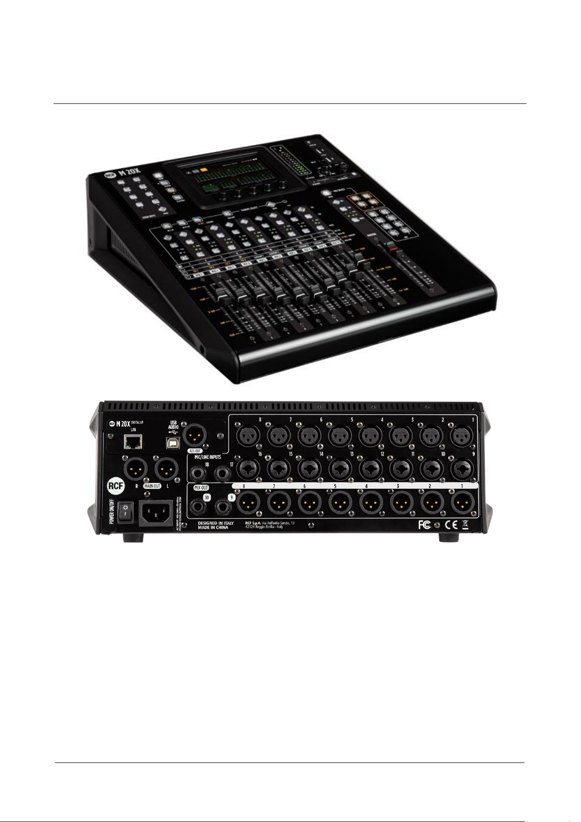
M 20 series products offer all-in-one mixing, processing and routing capabilities, including a comprehensive set of
recording and playback functions. The User Interface has been designed so that every parameter is reachable within
few operations. All models are equipped with 20 analog inputs (16 of which are with remote controlled preamps) and
14 output channels, between the balanced analog outputs and the AES/EBU digital output.
M 20 series digital mixing consoles are based on floating-point DSP (digital signal processors), running at a sample rate
of 48 kHz, ensuring maximum audio quality and low noise floor, an essential requirement for modern audio applications.
Page 2

RCF spa
M 20X Digital Mixer User’s Manual
2
Sommario
1. OVERVIEW .................................................................................................................................................................. 4
Hardware Description ..................................................................................................................................................... 4
System Overview ............................................................................................................................................................ 8
2. FIRMWARE UPDATE .................................................................................................................................................... 9
FIRMWARE UPDATE PROCEDURE ................................................................................................................................... 9
3. BACKUP & RESTORE .................................................................................................................................................. 11
BACKUP FUNCTION PROCEDURE .................................................................................................................................. 11
RESTORE FUNCTION PROCEDURE ................................................................................................................................. 12
4. PROCESSING ............................................................................................................................................................. 14
INPUT PROCESSING....................................................................................................................................................... 14
CHANNEL SECTION .................................................................................................................................................... 15
GATE SECTION........................................................................................................................................................... 17
PARAMETRIC EQ ....................................................................................................................................................... 18
DYNAMICS – Compressor/DeEsser ........................................................................................................................... 20
SENDS........................................................................................................................................................................ 22
OUTPUT PROCESSING ................................................................................................................................................... 24
CHANNEL VIEW ......................................................................................................................................................... 25
8-Band PARAMETRIC EQ ........................................................................................................................................... 26
DYNAMICS – Master Compressor/Limiter ................................................................................................................ 28
30-Band GRAPHIC EQ ................................................................................................................................................ 29
EFFECTS ......................................................................................................................................................................... 30
REVERB ..................................................................................................................................................................... 31
DELAY ........................................................................................................................................................................ 32
MODULATION ........................................................................................................................................................... 33
FX RETURN ................................................................................................................................................................ 34
MONITORING ................................................................................................................................................................ 35
METERS ..................................................................................................................................................................... 35
RTA ............................................................................................................................................................................ 35
PHONES ..................................................................................................................................................................... 36
PLAY/REC ...................................................................................................................................................................... 37
SETUP ........................................................................................................................................................................ 37
PLAYER ...................................................................................................................................................................... 38
RECORDER ................................................................................................................................................................. 39
5. SYSTEM ..................................................................................................................................................................... 41
SHOW ............................................................................................................................................................................ 41
NETWORK AND WIFI ..................................................................................................................................................... 42
USER KEYS ..................................................................................................................................................................... 42
I/O ROUTING ................................................................................................................................................................. 44
INPUTS ...................................................................................................................................................................... 44
OUTPUTS ................................................................................................................................................................... 45
Page 3

RCF spa
M 20X Digital Mixer User’s Manual
3
REC OUTPUTS............................................................................................................................................................ 45
STREAM OUTPUTS .................................................................................................................................................... 46
ROUTUNG PRESETS ................................................................................................................................................... 46
MUTE AND DCA GROUPS .............................................................................................................................................. 47
UTILITIES ....................................................................................................................................................................... 48
AUDIO OUTPUTS ....................................................................................................................................................... 48
SURFACE UTILITIES .................................................................................................................................................... 48
CUSTOM FADERS ...................................................................................................................................................... 48
CONFIG MIXER .......................................................................................................................................................... 49
TALKBACK.................................................................................................................................................................. 49
USB & SD CARD FORMAT .......................................................................................................................................... 50
SIGNAL GENERATOR ................................................................................................................................................. 50
CHANNEL UTILITIES ................................................................................................................................................... 50
INFO .............................................................................................................................................................................. 52
USB STORAGE ............................................................................................................................................................... 52
IMPORT ..................................................................................................................................................................... 53
EXPORT ..................................................................................................................................................................... 54
MIDI SETTINGS .............................................................................................................................................................. 55
MIDI MAPPING.......................................................................................................................................................... 55
6. VIEW BUTTONS ......................................................................................................................................................... 57
FADER SELECT VIEW...................................................................................................................................................... 57
USER KEYS VIEW ........................................................................................................................................................... 57
7. TECHNICAL SPECIFICATIONS ..................................................................................................................................... 58
8. BLOCK DIAGRAM ...................................................................................................................................................... 60
Page 4
RCF spa
M 20X Digital Mixer User’s Manual
4
1. OVERVIEW
Hardware Description
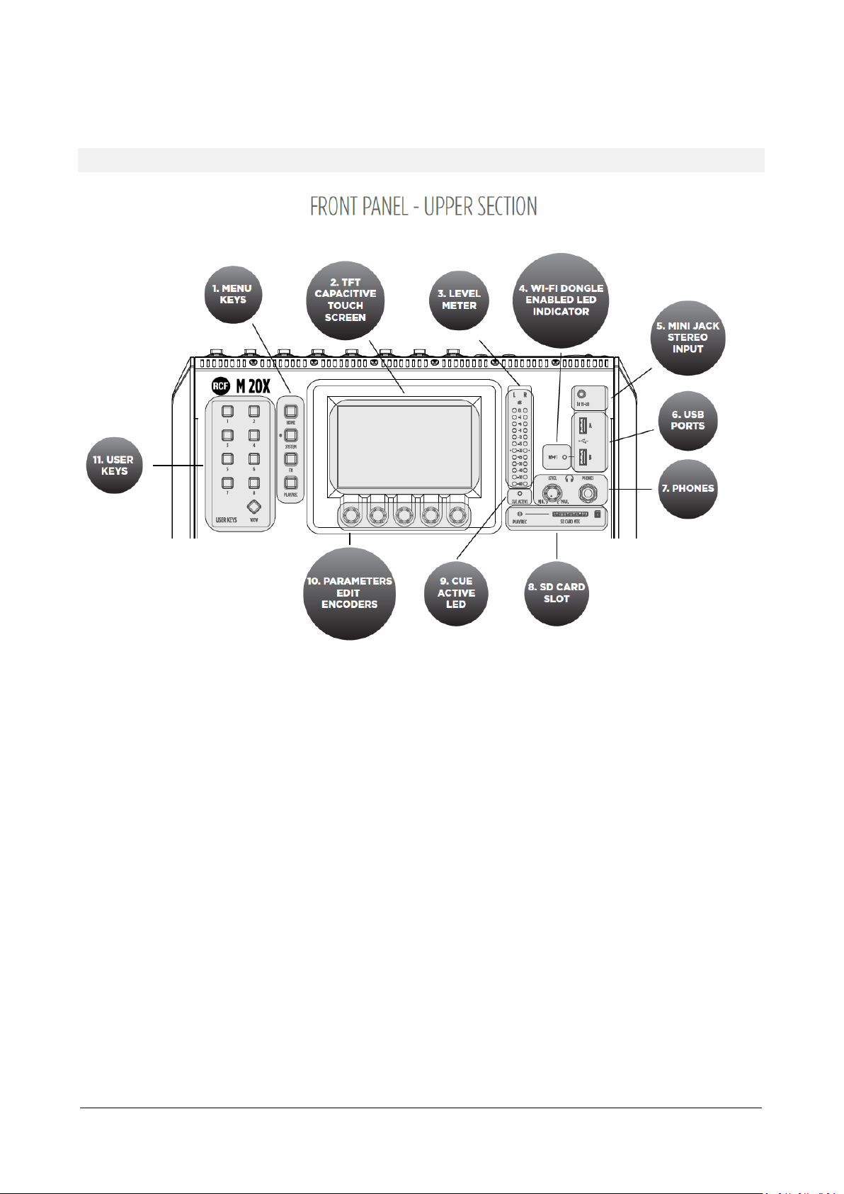
1. MENU KEYS
4 menu keys allow an intuitive and immediate navigation through menu pages.
2. TFT CAPACITIVE TOUCH SCREEN
A highly responsive 5-inch TFT touchscreen offers intuitive navigation of all the available features, and can be
optionally paired with an external tablet to augment interaction with the M 20X.
3. LEVEL METER
This 12 LED elements level meter normally allows you to control the Main Mix output level. When a channel
CUE button is pressed, the level meter shows the PFL level present in the selected channel. Keep the input level
below the “-20” indication to avoid overloaded signals that can cause distortion.
4. WI-FI DONGLE ENABLED LED INDICATOR
This led light up when the WI-FI AP function for the USB port “B” is enabled, allowing the use of a WiFi USB
dongle.
5. MINI JACK STEREO INPUT 19-20
Connect here your stereo line level sources like smartphones, laptops or others external audio devices.
6. USB PORTS
Two USB host ports on the top panel are available for WiFi dongles, USB-MIDI devices, and USB mass storage
devices that can be used for stereo audio record/ playback, system backups and firmware updates.
7. PHONES
Connect your headphones here either for CUE or the Main Mix listening.
Page 5
RCF spa
M 20X Digital Mixer User’s Manual
5
8. SD CARD SLOT
An integrated SD card multitrack engine offers a maximum of 20 simultaneous tracks at 24-bit, 48 kHz, with
extensive routing options.
9. CUE ACTIVE LED
This led light up when one or more CUE button are pressed.
10. PARAMETERS EDIT ENCODERS
5 dedicated encoders allow an intuitive and immediate control of each function and parameter on the screen.
11. USER KEYS
A set of 8 User Keys with extensive programming option are always available, and offers immediate control of
scene selection, play/record transport, tap tempo, user interface shortcuts. The USER KEYS functions can also
be driven remotely via MIDI (through a MIDI-USB interface).
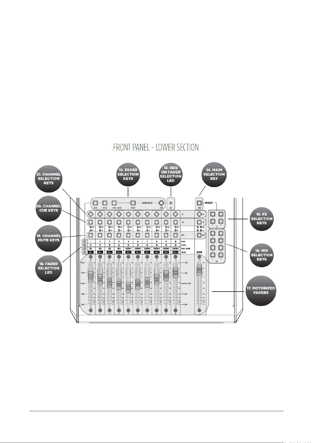
12. FADER SELECTION KEYS
4 layers of faders assignments allow immediate access to input channels 1-10 and 11-20, to FX returns and
outputs.
13. GEQ ON FADER SELECTION LED
This LED lights up when the function Graphic EQ on Fader is enabled.
14. MAIN SELECTION KEY
The control surface can be assigned to the stereo MAIN mix buss; the MASTER fader is always associated to
the output level of the selected bus.
Page 6
RCF spa
M 20X Digital Mixer User’s Manual
6
15. FX SELECTION KEYS
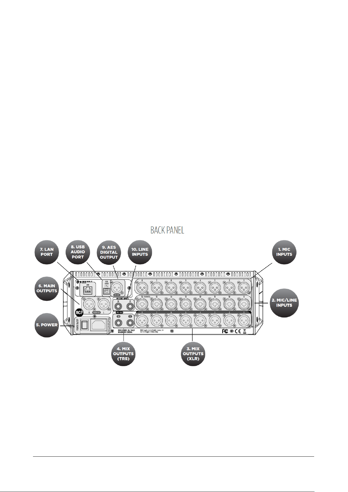
1. MIC Inputs 1-8 Female XLR
Connect your Microphones to these remotely-controlled 60dB gain-range inputs. Use balanced XLR cables to obtain
best performance from your microphones.
2. MIC/LINE Inputs 9-16 Combo
Input 9 to 16 provide Mic inputs on the XLR connection and Line input on the TRS jack connection.
3. MIX Outputs 1-8 Male XLR
Connect to these +24dBu balanced XLR outputs your stage monitors or external effects.
RCF spa
The control surface can be assigned to 4 FX busses; the MASTER fader is always associated to the output level
of the selected bus.
16. MIX SELECTION KEYS
The control surface can be assigned to 8 MIX busses; the MASTER fader is always associated to the output level
of the selected bus.
17. MOTORIZED FADERS
11 x 100-mm motorized faders allow precise mix control with immediate visual feedback. Special care has been
taken to minimize movement noise.
18. FADER SELECTION LED
These 4 leds light to show the current assigned layer of faders.
19. CHANNEL MUTE KEYS
MUTE buttons when pressed inhibit the signal to flow to output bus or main mix paths.
20. CHANNEL CUE KEYS
The CUE keys allow to listen the signal present on the channel, through the cue bus routed to PHONES OUTPUT.
All audio paths can be monitored at any time via the CUE bus, which features a real‑time analyzer (RTA).
21. CHANNEL SELECTION KEYS
The SELECTION KEYS allow an intuitive and immediate navigation through channel functions and parameters.
Page 7

M 20X Digital Mixer User’s Manual
7
4. MIX Outputs 9-10 TRS
Connect to these +24dBu balanced TRS outputs your stage monitors or external effects.
5. POWER
Use this switch to turn On and Off your M 20X device. Connect to the VDE inlet the provided power cord.
6. MAIN OUTUT
Connect your active speaker or your amplifier, in case of passive speakers, to these +24dBu balanced Output.
7. LAN PORT
The mixer can be remotely controlled via LAN, and an external Wi-Fi Access Point can be connected to the LAN port
to communicate with remote control apps running on iOS and Android.
8. USB AUDIO PORT
A 24-track. 24-bit, 48-kHz audio interface is available and allows access to all inputs and several internal signal nodes.
Extensive routing options allow both offline sound check and host-based effects processing.
9. AES DIGITAL OUTPUT
Connect here any AES/EBU device. Each of the audio output paths is routable to the AES/EBU port.
10. LINE INPUTS 17-18 TRS
Connect here your line level sources like keyboard, external audio device or other small analog consoles used for
submix.
Page 8
RCF spa
M 20X Digital Mixer User’s Manual
8
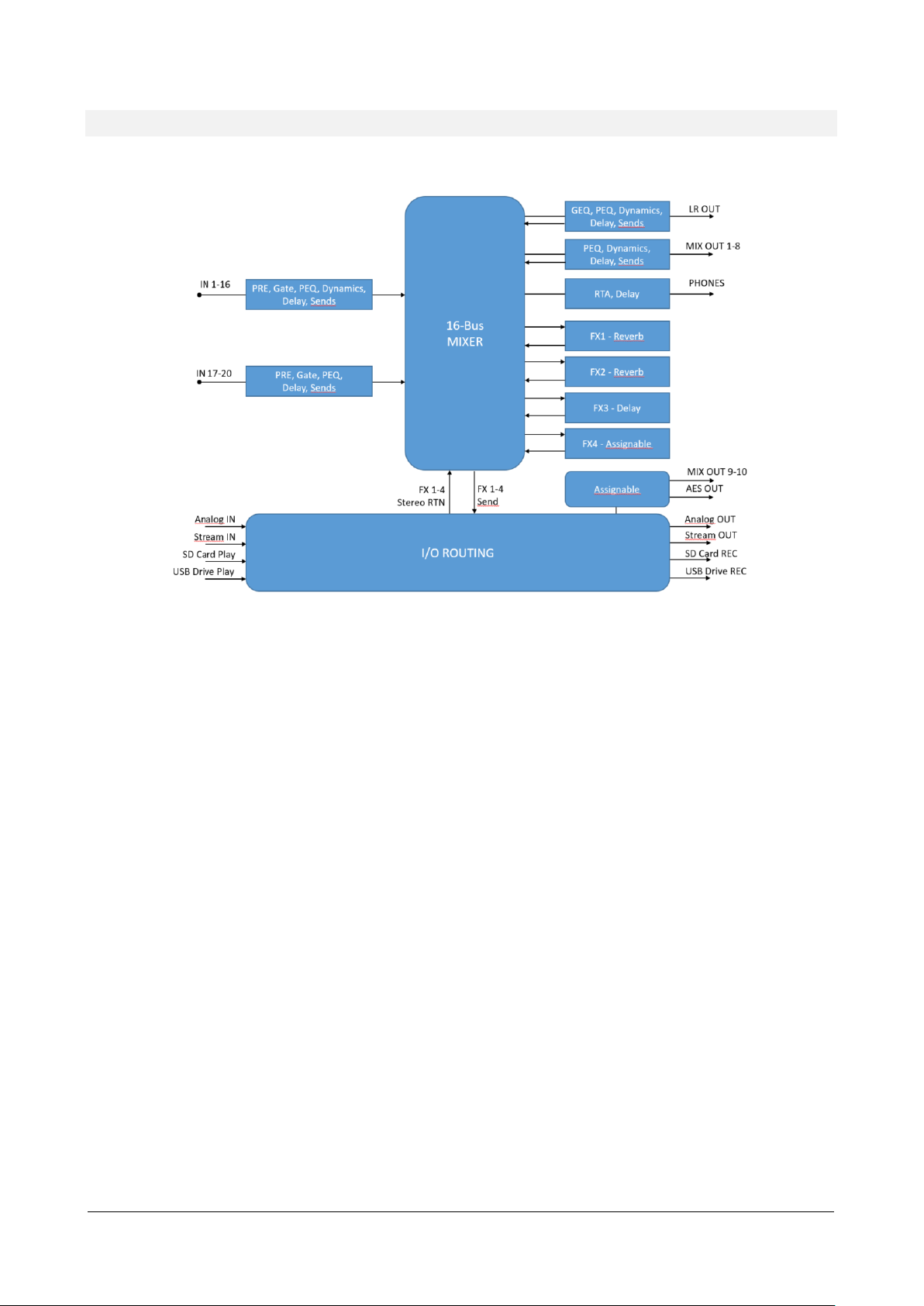
System Overview
The M 20X Digital Mixer is a feature-packed unit that includes several of the useful blocks required to arrange a goodsounding live act.
Signal processing capabilities of the M 20X Digital Mixer
A total of 16 summing bus are present in the M 20 Digital Mixer:
MAIN LR bus
FX SEND 1-4 bus
MIX SEND 1-8 bus
Stereo PHONES bus
Each of the 20 inputs features a 12 dB/oct HPF, a noise Gate, a Compressor/De-Esser (inputs 1-16 only), a flexible 4band Parametric EQ, and a Delay line. The source can be selected between the analog inputs, the USB audio interface,
the SD card player, into different insertion points for maximum flexibility.
M 20X boast 4 stereo FX engines available on dedicated busses, offering two high quality digital reverbs,
a programmable delay and a 4th effect which can be configured as a modulation or a second delay. All FX Engines offer
multiple algorithms to match the specific needs of a show.
A complete processing section is available on all outputs: a flexible 8-band Parametric EQ with several selectable modes
that also allow different slopes, a Delay with up to 85 meters compensation, a Compressor/Limiter. A stereo 30-band
Graphic Equalizer is available on the MAIN outputs for precise correction of the overall frequency response.
Extensive routing capabilities are available in the M 20 Digital Mixers to provide a wide flexibility for your live and studio
sessions.
A fast reacting 5-inch capacitive touchscreen, 5 dedicated encoders and 4 menu keys allow an intuitive and immediate
control of every function and parameter. You have full control of your live mix, all within one of the most compact
systems on the market.
Page 9
RCF spa
M 20X Digital Mixer User’s Manual
9
2. FIRMWARE UPDATE
FIRMWARE UPDATE PROCEDURE
1. Download the latest firmware package available on the web page
https://www.rcf.it/en_US/products/mixing-consoles/m-series/m-20-firmware-update
2. Unzip the .zip file and copy the RCF-M20X-xxxx.mpk file on the root directory of a FAT32 formatted USB
stick. Be sure to have one .mpk file only in the USB stick, to avoid file mismatch.
3. Turn on the M 20X digital mixer.
4. Once the boot is completed, pressing SYSTEM button on the left side of the 5” touchscreen display, go to the
page SYSTEM > UTILITIES > FIRMWARE UPDATE.
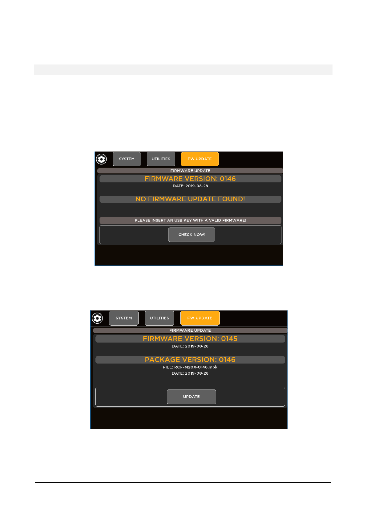
5. Insert your USB stick into the USB A port. The upper side shows the firmware version that is currently
installed on the mixer. The bottom side shows the firmware version on the USB stick ready to be installed.
6. If the new package is not automatically detected, please press CHECK NOW
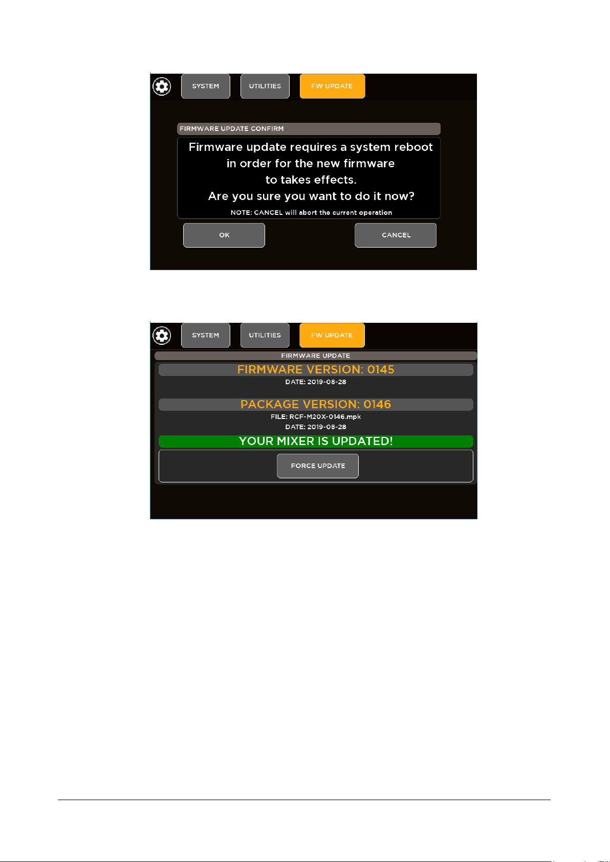
7. Once the new package is detected, press UPDATE and then confirm the system reboot required to apply the
new firmware.
Page 10
RCF spa
M 20X Digital Mixer User’s Manual
10
8. After a few seconds you will see a confirmation notice before mixer restart.
9. After rebooting the new features will be ready to be enjoyed.
Page 11

RCF spa
M 20X Digital Mixer User’s Manual
11
3. BACKUP & RESTORE
M 20 series digital mixers provide backup and restore utilities to save and recall the entire state of the mixer, including
all presets, shows and global settings.
BACKUP FUNCTION PROCEDURE
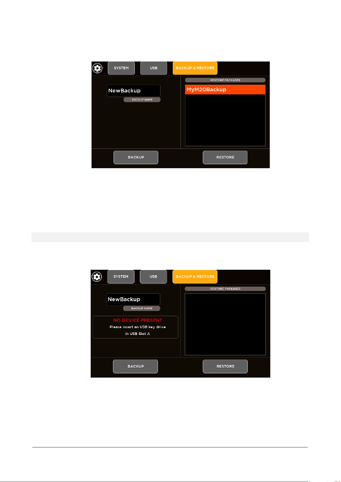
1. Go to page SYSTEM > USB STORAGE > BACKUP & RESTORE
2. If you do not connect a USB key drive, this screen will appear:
3. Insert your USB stick into the M 20 USB port A
Page 12
RCF spa
M 20X Digital Mixer User’s Manual
12
4. Type a name (a single word without space and special characters) of your backup in the BACKUP NAME area
and then press the BACKUP button.
5. A full backup has been successfully created on the root of the USB stick (* .mbu file). The backup packages will
be listed in the box on the right side of the page, ready to be restored.
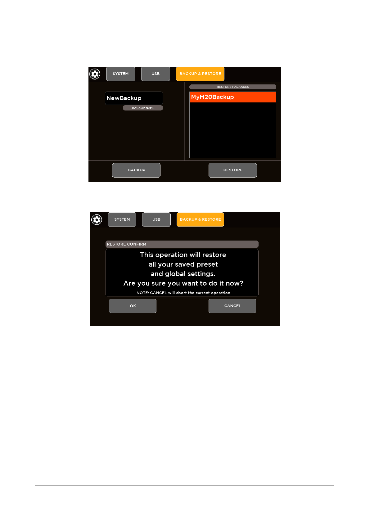
RESTORE FUNCTION PROCEDURE
1. Go to page SYSTEM > USB STORAGE > BACKUP & RESTORE
2. If you do not connect a USB key drive, this screen will appear:
Page 13
RCF spa
M 20X Digital Mixer User’s Manual
13
3. Insert your USB stick into the M 20 USB port A
4. From the list box in the right side of the page select the backup package that you want load on your mixer and
then press RESTORE button. A message box will appear:
5. If you want to proceed, click on “OK”
6. The restore procedure has been completed
Page 14
RCF spa
M 20X Digital Mixer User’s Manual
14
4. PROCESSING
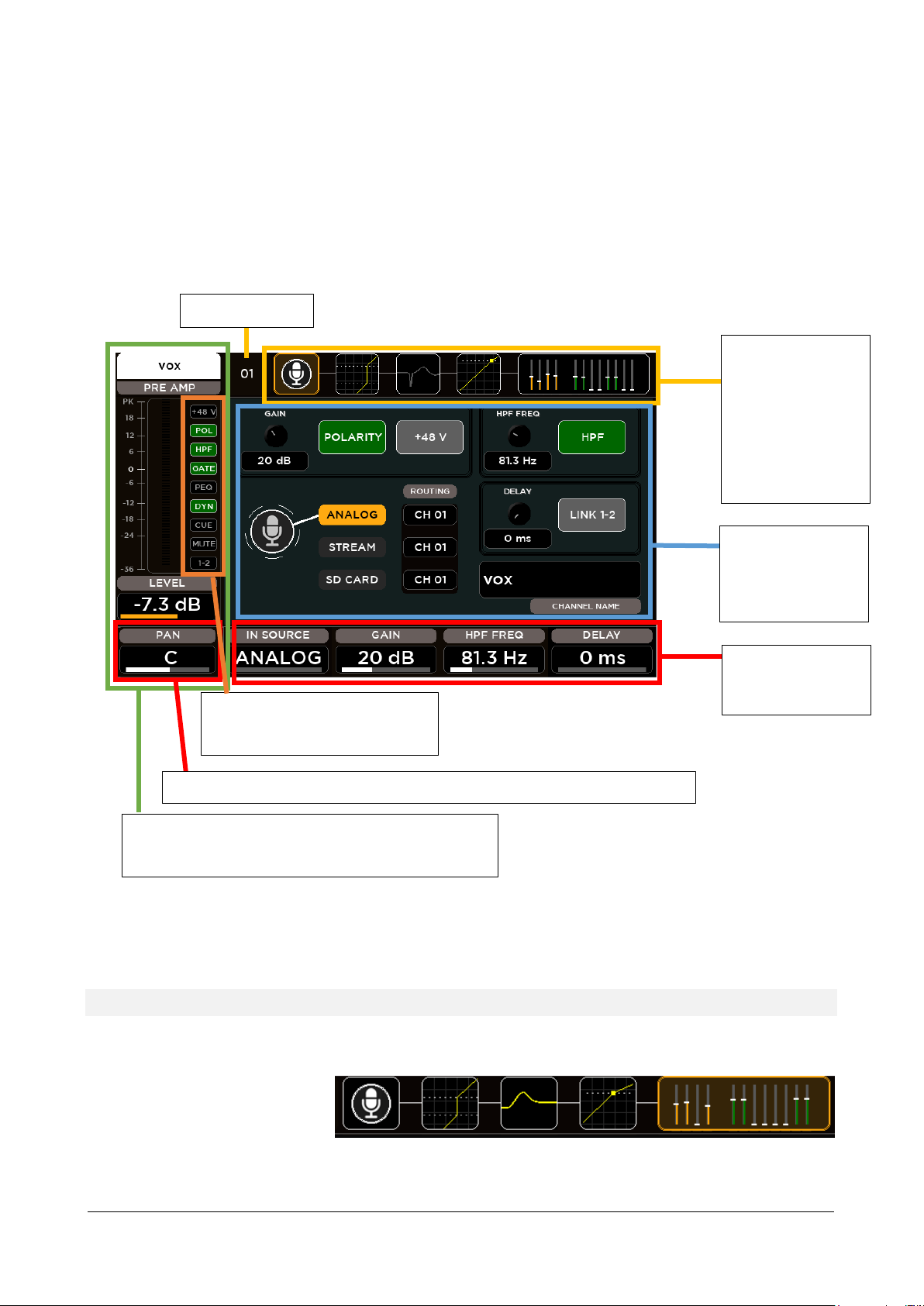
Channel strip area that always shows the principal information
of the selected channel: name, meter bar, fader level value,
pan value and on-off processing status bar
Processing Tabs:
Touch the block or
press SEL to change
view. The yellow
outline indicate the
current view. Each
block also shows the
preview of processing
settings.
This status bar shows the on-off
status of each function available on
the selected channel.
Encoder parameters
change accordingly to
the processing page
Processing section
hold touch buttons
and display boxes of
to the encoders
values
Channel Number
Encoder 1 is fixed to PAN control related to the selected Input or Output channel
Press any SEL button to select a channel and the touchscreen will display the dedicated channel processing. The display
will automatically change every time the SEL button is pressed in order to cycling between the single processing pages.
It’s also possible to select the processing block touching the processing tabs on the upper side of the screen. Once a
block is selected, the display changes accordingly and the parameters available in that section are assigned to surface
encoders below the screen.
INPUT PROCESSING
The Input Processing screen is divided into the following tabs (from left to right):
CHANNEL
GATE
PARAMETRIC EQ
DYNAMICS
You can touch each of these section to jump to the relevant page.
SENDS
Page 15
RCF spa
M 20X Digital Mixer User’s Manual
15
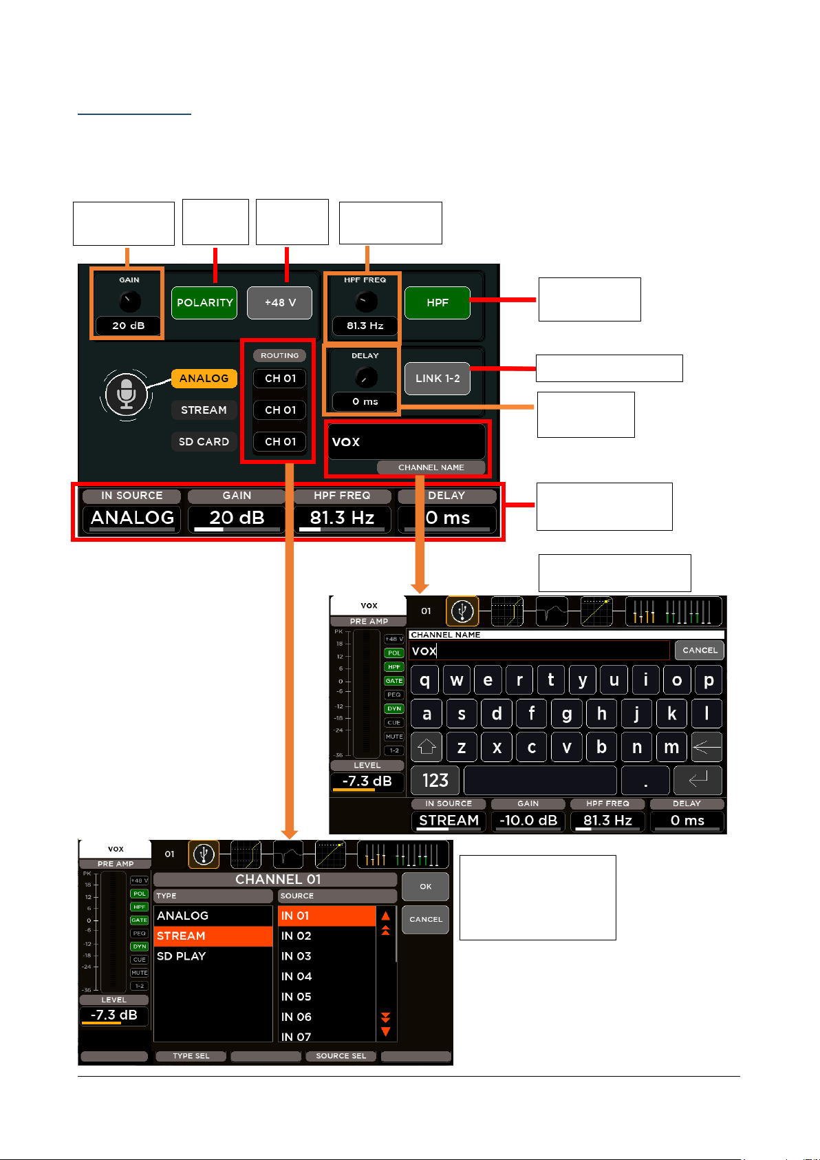
CHANNEL SECTION
PREAMP GAIN
Value display
Phase
inverter
12 dB/oct HPF
On/Off
Encoder Parameters
assignment
Channel Rename
Stereo Pairing Enable
Phantom
Enable
Delay Time
value display
HPF frequency
value display
Set the Input Routing:
for each source type select
which input is routed to
the selected channel
processing
The first block allow the channel settings accordingly to the input.
Input channels 1-16
Page 16
RCF spa
M 20X Digital Mixer User’s Manual
16
The CHANNEL parameters assigned to the Encoders are:
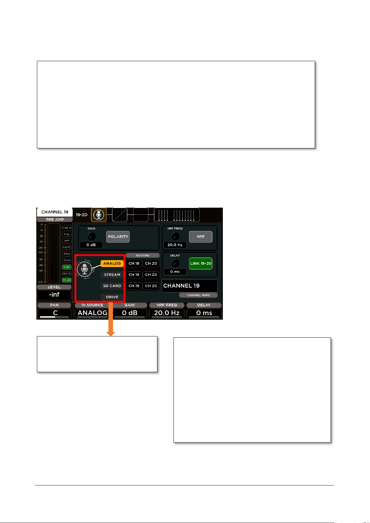
IN SOURCE: this parameter allows to select the source type between these items:
Input channels 19-20 have an additional
item in the Source Selector. Besides Analog,
Stream and SD Card source, it’s possible to
select USB Stereo Player as input.
IN SOURCE: this parameter allows to select the source type
GAIN: this parameter set the value of the input gain
ANALOG: Mic Input
STREAM: 24-track USB audio interface
SD CARD: 20-track Player
GAIN: this parameter set the value of the input gain accordingly to the selected input source
ANALOG: range [0: 60] dB with step of 1 dB
STREAM: range [-10: 10] dB with step of 1 dB
SD CARD: range [-10: 10] dB with step of 1 dB
HPF FREQ: this parameter set the value of the HPF cutoff frequency in the range [20: 1k] Hz
DELAY: this parameter set the value of the input Delay time in the range [0: 100] ms
Input channels 17-20
Hardware inputs from 17 to 20 have line connections, with no Phantom option and with the preamp gain parameter in
the range [0: 10] dB.
between these items:
ANALOG: Mic Input
STREAM: 24-track USB audio interface
SD CARD: 20-track Player
DRIVE: USB Stereo Player (for CH19-20 only)
accordingly to the selected input source
ANALOG: range [0: 10] dB with step of 1 dB
STREAM: range [-10: 10] dB with step of 1 dB
SD CARD: range [-10: 10] dB with step of 1 dB
DRIVE: range [-10: 10] dB with step of 1 dB
Page 17
RCF spa
M 20X Digital Mixer User’s Manual
17
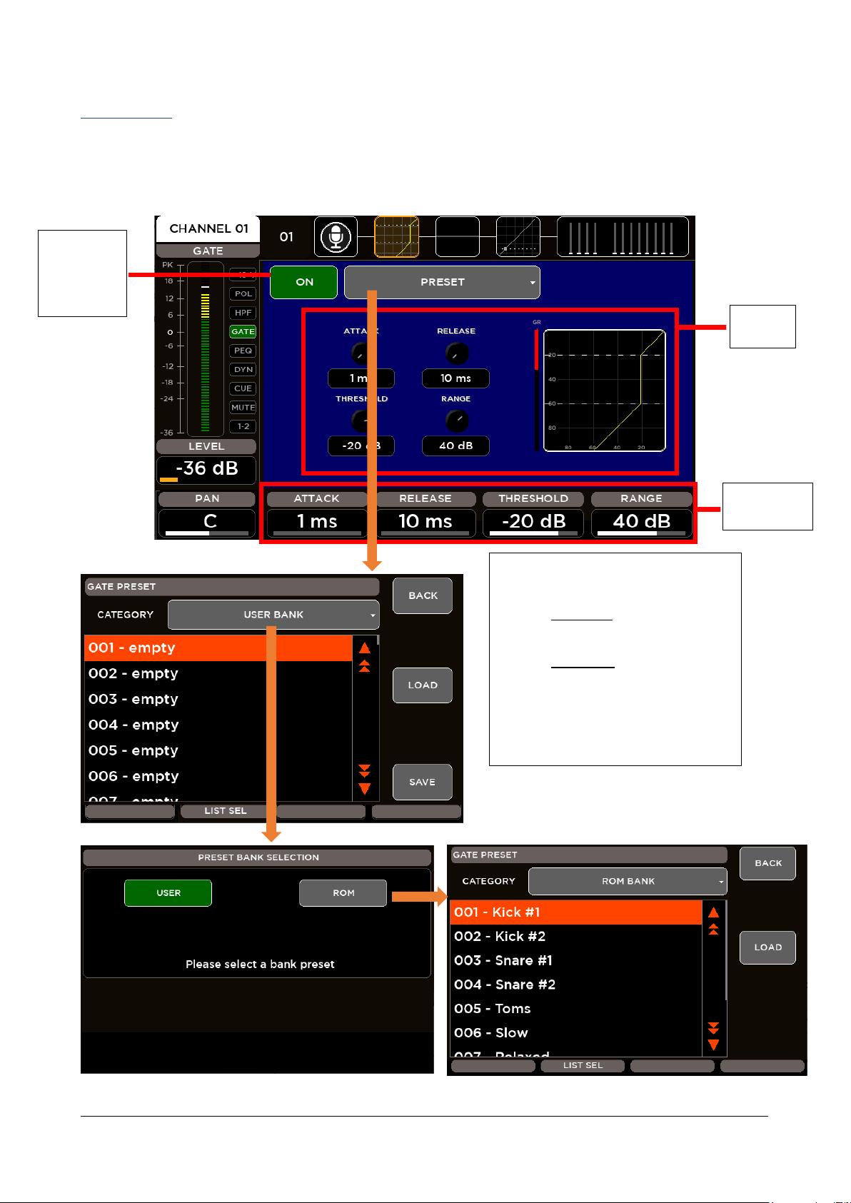
GATE SECTION
Viewing
Area
Encoder
Assignment
Switch the
Gate On or
Off using the
on-screen
ON button
Preset View shows the last chosen category
of presets. For the GATE block are available
2 banks of presets:
USER BANK – 100 locations where
save your custom settings.
ROM BANK – 10 locations with
carefully crafted presets.
Press BACK to return to processing page.
Choose your preset directly scrolling on the
screen or using the Encoder 3 (LIST SEL),
then press LOAD to recall it.
All inputs are equipped with a Noise Gate processor that allows to reduce the output signal by a specific amount (Range)
when the input signal level is lower than a specific amount (Threshold). A gain reduction level (visible also when the
processor is off) allows to set all parameters before hearing the effective sound.
Page 18
RCF spa
M 20X Digital Mixer User’s Manual
18
The GATE parameters assigned to the Encoders are:
ATTACK: this parameter allows to set the value of the Attack Time in the range [1: 1000] ms
RANGE: set the value of the Range in the range [0: 60] dB
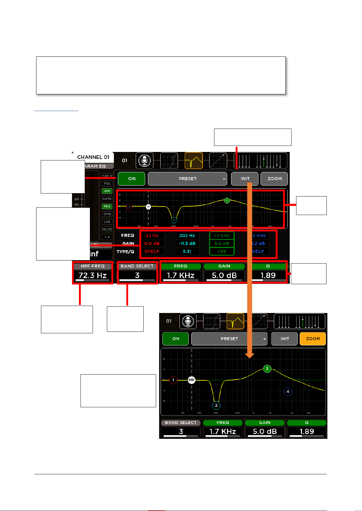
Switch the PEQ
On or Off using
the on-screen
ON button
Touch these boxes
to select a band and
automatically
assign the 3
rightmost encoders
to the related
parameters
Encoder
Assignment
Reset the EQ parameters using
the INIT button
Select band
rotating
Encoder 2
Viewing
Area
ZOOM View allows a more
accurate setting of the
equalizer curve using touch
screen
View and adjust
HPF frequency in
the EQ page also.
RELEASE: this parameter allows to set the value of the Release Time in the range [10: 1000] ms
THRESHOLD: set the value of the Threshold in the range [-100: 0] dB
PARAMETRIC EQ
All inputs are equipped with a 4-band Parametric EQ that allows an accurate equalization of signal input.
Page 19

RCF spa
M 20X Digital Mixer User’s Manual
19
For the input Parametric Equalizers are available
10 banks of presets divided into categories:
USER BANK – 100 locations where
save your custom settings.
ROM BANKS
o DRUM
20 locations with carefully crafted
drum presets
o PERCUSSION
10 locations with carefully crafted
percussion presets
o BASS
10 locations with carefully crafted
bass presets
o EL. GUITAR
10 locations with carefully crafted el.
guitar presets
o AC. GUITAR
10 locations with carefully crafted ac.
guitar presets
o KEYBOARD
10 locations with carefully crafted
keyboard presets
o VOICE
10 locations with carefully crafted
voice presets
o ORCHESTRA
10 locations with carefully crafted
orchestra presets
o MISC
10 locations with carefully crafted
miscellaneous presets
Press BACK to return to processing page.
Choose your preset directly scrolling on the
screen or using the Encoder 3 (LIST SEL), then
press LOAD to recall it.
Page 20

RCF spa
M 20X Digital Mixer User’s Manual
20
PEQ parameters assigned to the Encoders are:
BAND SELECT: this parameter allows to select the single filter band
Switch the
DYN On or
Off using the
on-screen
ON button
Viewing Area
and assign
Parameters
Encoder
Assignmen
Switch DE-ESSER
On to enable the
De-Esser mode.
Switch DE-ESSER
Off to enable the
Compressor mode.
Touch & Adjust
function is available for
ATTACK, RELEASE and
FREQ. Touch one of
these parameters and
adjust the value using
Encoder 5.
When in De-Esser mode select
the Filter Type (between High
Pass and Band Pass) of the Side
Chain and adjust the Frequency
The yellow label
indicates which
parameter has been
assigned to ENCODER 5
FREQ: set the value of Frequency of the selected band in the range [20: 20k] Hz
GAIN: set the value of Gain of the selected band in the range [-12: 12] dB
TYPE/Q: this parameter change according to the selected filter band:
Band1
o Low SHELF Filter type
o HP Filter type
o Peaking Filter Q parameter in the range [1: 20]
Band2 & Band3
o Peaking Filter Q parameter in the range [1: 20]
Band4
o High SHELF Filter type
o LP Filter type
o Peaking Filter Q parameter in the range [1: 20]
DYNAMICS – Compressor/DeEsser
All 16 MIC inputs are equipped with a Dynamics processor that can be setted as Compressor or as De-Esser.
Page 21

RCF spa
M 20X Digital Mixer User’s Manual
21
THRESHOLD: set the value of the compressor threshold in the range [-80: 0] dB
For the input Parametric Equalizers are available
10 banks of presets divided into categories:
USER BANK – 100 locations where
save your custom settings
ROM BANKS
o COMPRESSOR
10 locations with carefully
crafted compressor presets
o DE-ESSER
10 locations with carefully
crafted de-esser presets
Press BACK to return to processing page.
Choose your preset directly scrolling on the
screen or using the Encoder 3 (LIST SEL), then
press LOAD to recall it.
DYN parameters assigned to the Encoders are:
RATIO: set the value of the Ratio in the range [1: 20]
POST GAIN: set the value of Gain of in the range [-30: 30] dB
ASSIGNABLE: this parameter change according to the selected parameter:
ATTACK: set the value of the Attack Time in the range [1: 1000] ms
RELEASE: set the value of the Release Time in the range [1: 1000] ms
FREQ: set the value of the Side Chain Frequency in the range [200: 8000] Hz
Page 22

RCF spa
M 20X Digital Mixer User’s Manual
22
SENDS
APFL channel send
PRE / POST
ON/OFF
4 FX channel sends
PRE / POST
ON/OFF
Level
8 MIX channel sends
PRE / POST
ON/OFF
Level
DCA and MUTE
GROUPS assignment
Encoder
Assignment
Select Send block by
moving Encoder 2
SEND SEL: this parameter allows to select the single send-on-mix block
LEVEL: according to the send type, this parameter allows to set the send level in the range [-inf: +10] dB
For each input channel, the SENDS page allows to control all channel sends to every mix bus: FX [1-4], MIX [1-8], and
APFL. For each send-on-mix are available different parameters: Pre/Post, on/off and Level.
The encoder parameters change according to the selected block send-on-mix.
The SENDS parameters assigned to the Encoders are:
PRE/POST: this parameter allows to select if the selected send-on-mix is Pre or Post Fader
ON/OFF: this parameter allows to enable or disable the selected send-on-mix
Page 23

RCF spa
M 20X Digital Mixer User’s Manual
23
CHANNEL PRESET
M 20 digital mixers provide 100 locations
where save your custom settings of all input
processing chain.
Press BACK to return to processing page.
Choose your preset directly scrolling on the
screen or using the Encoder 3 (LIST SEL),
then press LOAD to recall it.
COPY & PASTE
M 20 digital mixers provide the possibility to
copy the current processing parameters of a
channel and to paste them to other channels.
Press COPY on the channel that you want to
replicate.
Go to desiderata channel, press PASTE and
select which processing blocks you want to
overwrite selecting the relative buttons.
Page 24

RCF spa
M 20X Digital Mixer User’s Manual
24
OUTPUT PROCESSING
Channel Name
Meter bar
Fader Level Value
Balance Value
On-Off
processing
status bar
Processing Tabs: Touch the block or press SEL to
change view. The yellow outline indicate the
current view. Each block also shows the preview
of processing settings.
Output
Channel
Encoder parameters change
accordingly to the processing page
Current Page
A complete processing section is available on all outputs: a flexible 8-band parametric EQ with several selectable modes,
that also allow different slopes, a delay with up to 85 meters compensation, a compressor/limiter. A stereo 30-band
graphic equalizer is available on the MAIN outputs for precise correction of the overall frequency response. Extensive
routing options allows flexible use of physical outputs.
The MIX [1:8] output processing screen is divided into the following tabs:
CHANNEL VIEW
PARAMETRIC EQ
DYNAMICS
The Main LR processing screen is divided into the following tabs:
CHANNEL VIEW
GRAPHIC EQ
PARAMETRIC EQ
DYNAMICS
Similarly to the input channels, the left side of the screen doesn’t change when navigate between the processing pages
of the channel. The left column is the Channel strip that shows the principal information of the selected channel: name,
meter bar, fader level value, balance value (for the stereo channels) and on-off processing status bar.
Page 25

RCF spa
M 20X Digital Mixer User’s Manual
25
CHANNEL VIEW
COPY & PASTE
COPY the current processing parameters of an
output and to paste them to other outputs.
Go to desiderata output, press PASTE and select
which processing blocks you want to overwrite
selecting the relative buttons.
Send the output mix channel to:
APFL bus to monitoring and analyzing the audio mix
LR bus if you want to use mix as a subgroup
DCA and MUTE
GROUPS
assignment
Encoder
Parameters
Stereo Pairing Enable
CHANNEL PRESET
M 20 digital mixers provide 100 locations where
save your custom settings of all input processing
chain.
Press BACK to return to processing page.
Choose your preset directly scrolling on the screen
or using the Encoder 3 (LIST SEL), then press LOAD
to recall it.
Channel
Rename
(Press
Enter to
confirm)
The first page allows the channel settings accordingly to the output.
Page 26

RCF spa
M 20X Digital Mixer User’s Manual
26
CHANNEL VIEW parameters assigned to the Encoders are:
SEND SEL: this parameter allows to select the send-on-mix block:
Encoder parameters change
according to the selected band
Select band moving
Encoder 2
Switch the
PEQ On or Off
using the onscreen ON
button
Touch these
boxes to select
a band and
automatically
assign last 3
encoder to the
related
parameters
Reset the EQ parameters
using the INIT button
Viewing
Area
For the output Parametric EQ, 100
locations are available where your custom
settings can be saved and recalled
ZOOM View
allows a more
accurate setting
of the equalizer
curve using touch
screen
Send to APFL (for LR and MIX outputs)
Send to LR (for MIX outputs only)
PRE/POST: this parameter allows to select if the selected send-on-mix is Pre or Post Fader
ON/OFF: this parameter allows to enable or disable the selected send-on-mix
DELAY: this parameter set the value of the input Delay time in the range [0: 250] ms
8-Band PARAMETRIC EQ
All outputs are equipped with an 8-band Parametric EQ that allows an accurate equalization of signal output and that
can be configured in various operating modes: the first two and last two bands have selectable filter types, and they can
be combined into a single, 24-dB/oct HPF or LPF. This also allows for crossover filtering, useful in combination with the
extensive routing capabilities, when a subwoofer is connected to one of the MIX outputs.
Page 27

RCF spa
M 20X Digital Mixer User’s Manual
27
PEQ8 Operating Modes
BAND SELECT: this parameter allows to select the single filter band
PEQ parameters assigned to the Encoders are:
FREQ: set the value of Frequency of the selected band in the range [20: 20k] Hz
GAIN: set the value of Gain of the selected band in the range [-12: 12] dB
TYPE/Q: this parameter change according to the selected filter band:
Band1
o Low SHELF Filter type
o High Pass 12 dB/oct Filter type
o High Pass 24 dB/oct Filter type Band1 combined with Band2
o Peaking Filter Q parameter in the range [1: 20]
Band2, Band3, Band4, Band5, Band6, Band7
Band8
o Peaking Filter Q parameter in the range [1: 20]
o High SHELF Filter type
o Low Pass 12 dB/oct Filter type
o Low Pass 24 dB/oct Filter type Band7 combined with Band8
o Peaking Filter Q parameter in the range [1: 20]
Page 28

RCF spa
M 20X Digital Mixer User’s Manual
28
DYNAMICS – Master Compressor/Limiter
Switch the
DYN On or
Off using the
on-screen
ON button
Viewing
Area
Encoder
Assignment
For the output DYN are available 100
locations where save and recall your
custom settings.
All outputs are equipped with a Dynamics processor configured as a Compressor/Limiter
DYN parameters assigned to the Encoders are:
ATTACK: set the value of the Attack Time in the range [1: 1000] ms
RELEASE: set the value of the Release Time in the range [10: 1000] ms
THREASHOLD: set the value of the compressor threshold in the range [-80: 0] dB
RATIO: set the value of the Ratio in the range [1: 20]
Page 29

RCF spa
M 20X Digital Mixer User’s Manual
29
30-Band GRAPHIC EQ
Select frequency
zone moving
Encoder 4
Select filter band within
the selected zone moving
Encoder 2
Select frequency zone
touching one of the 3
areas:
Zone1
[25-200] Hz
Zone2
[250-2k] Hz
Zone3
[2k5-20k] Hz
The yellow line indicates
the selected frequency
zone
Select band touching
one of the 10 sliders
The yellow line
indicates the selected
band
Switch the
GEQ On or
Off using the
on-screen
ON button
For the GEQ, 100 locations are
available where your custom
settings can be saved and recalled
Set all band
gains to 0 dB
When enabled, the 10 input faders
control the 10 bands relative to the
selected frequency zone in order to allow
a fine control of each gain band
The Main OUT processing provides a 30-Band GEQ with the center frequency of each band spaced 1/3 of an octave
away from the center frequency of the adjacent bands, so that three bands (three sliders on the front panel) cover a
combined bandwidth of one octave.
GEQ parameters assigned to the Encoders are:
BAND SELECT: select one of the 10 bands for each selected zone
Zone1 Bands: 25, 31, 40, 50, 63, 80, 100, 125, 160, 200 Hz
Zone2 Bands: 250, 315, 400, 500, 630, 800, 1k, 1k25, 1k6, 2k Hz
Zone3 Bands: 2k5, 3k15, 4k, 5k, 6k3, 8k, 10k, 12k5, 16k, 20k Hz
GAIN: set the value of the selected band in the range [-12; +12] dB
ZONE SELECT: select the frequency zone
Page 30

RCF spa
M 20X Digital Mixer User’s Manual
30
EFFECTS
FX1 – REVERB
HALL: Large Bright/Warm, Medium Bright/Warm
PLATE: Vintage, Modern
ROOM: Medium Bright/Warm, Small Bright/Warm
AMBIENCE: 2 models
FX2 - REVERB
same Reverb models as FX1
FX Selection Tabs
Encoder
Assignment
FX Master
SEND
meter and
Level
Algorithm
Selection
Model
Selection
Preset recall
FX3 - DELAY
Stereo
Modern
Vintage
Dual
ER
FX4 – DELAY or MODULATION
same Delay models as FX3
Chorus
Flanger
Tremolo
All M 20 models boast 4 stereo FX engines available on dedicated busses, offering two high quality digital reverbs, a
programmable delay and a 4th effect which can be configured as a modulation or a second delay. All FX Engines offer
multiple algorithms to match the specific needs of a show. The internal effects pages are accessible through the FX
button on the left side of 5” TFT Display or through the SEL button on each Master FX strips.
FX ALGORITHM LIST
Page 31

RCF spa
M 20X Digital Mixer User’s Manual
31
REVERB
TYPE
VARIATIONS
Hall
usually perfect for smooth and deep reverberations
large/medium
warm/bright
Room
the algorithm to start with if you are looking for hi
impact reverberations
large/medium
warm/bright
Plate
classic “all purpose” algorithm with unique character
digital/vintage
Ambience
the first choice if you are looking for something to
expand the stereo field or to somehow enhance the
sounds
model 1, model 2
The M Series provides two simultaneous full Digital Reverbs available on Send FX1 and Send FX2. Digital Reverb is a
very intuitive and smooth sounding processor and represents an essential ingredient of the final mix. Great care has
been taken to provide the highest quality algorithms and presets.
Based on 12 algorithms, it allows to easily find the perfect reverberation for every kind of application in a few clicks. The
algorithms are been designed and tailored to focus immediately the sound you are looking for and then fine tune it with
the essential parameters available through the five pots.
The algorithms are also available in some cases into two variations (Bright/Warm or Digital/Vintage) to further help in
selecting the proper starting point.
Four different reverb types are available:
You can create your own configurations for Hall and Room by modifying the following parameters:
Predelay (delay before reverb)
ER (amount of primary reflections)
Decay (time decay)
Spaceness (percentage of spatialization)
Damping (percentage of absorption of the higher frequencies)
Page 32

RCF spa
M 20X Digital Mixer User’s Manual
32
Plate reverb parameters:
TYPE
VARIATIONS
Stereo
usually perfect for smooth and deep reverberations
large/medium
warm/bright
Vintage
the algorithm to start with if you are looking for hi impact
reverberations
large/medium
warm/bright
Modern
classic “all purpose” algorithm with unique character
digital/vintage
Dual
the first choice if you are looking for something to expand
the stereo field or to somehow enhance the sounds
model 1, model 2
ER
Early reflections to simulate the sound of a room without
introducing an audible tail
Smoothness
Colour
Ambience reverb parameters:
Richness
TIP
The reverberation is one of the most crucial signal processors to achieve a correct mix, so it’s very important to use it
with care. Often the reverberation of the venue affects our overall sound, especially because usually the sound check is
done without audience that is another element that can drastically change the reverberation time of the venue.
So keep in mid to evaluate the reverberation time of the empty venue, and then consider that it will be shorter with the
audience during the live gig; for these reasons, it could be useful to check the amount of the reverb also on headphones.
DELAY
The M Series provides two simultaneous full Digital Delays available on Send FX3 and Send FX4.
Five different delay types are available:
You can create your own settings for Stereo and ER by changing the following parameters:
Time (length of the delay)
Feedback (% of delay feedback)
Lo Cut (low cut filter frequency)
Hi Cut (high cut filter frequency)
Width (amplitude)
Vintage delay parameters:
Offset (offset time compared with main Time) instead of Feedback
Filter (da 0,00 a 100) is a Band-pass filter
Page 33

RCF spa
M 20X Digital Mixer User’s Manual
33
Modern delay parameters:
Offset (offset time related to main Time) instead of Feedback
LoCut (low cut filter frequency) instead of Hi Cut.
Dual delay parameters:
Factor (1/2, 1/3, 1/4, 1/6, 1/8 and 1/16) instead of Feedback
Feedback 2 (% of delay 2 feedback) instead of Hi Cut
MODULATION
The M Series provides a Modulation processor available on Send FX4. The Modulation processor can be configure as
Chorus-Flanger or as Tremolo effect.
Chorus-Flanger parameters:
Rate (frequency swing)
Width (amplitude)
Depth (depth swing)
Feedback (% effect feedback)
Blend (% mix between dry signal and processed)
Tremolo parameters:
Rate (frequency rate)
Depth (depth swing)
Page 34

RCF spa
M 20X Digital Mixer User’s Manual
34
FX RETURN
8 MIX FX sends
PRE / POST
ON/OFF
Level
APFL FX send
PRE / POST
ON/OFF
DCA and MUTE
GROUPS
assignment
Encoder
Assignment
Select Send block
moving Encoder 2
FX RETURN
strip parameters:
METER
LEVEL
PAN
FX RETURN ROUTING
M 20 digital mixers provide 5
sources for each FX return:
Internal FX
Stream USB IN 17-18
Stream USB IN 19-20
Stream USB IN 21-22
Stream USB IN 23-24
Press BACK to return to FX
Return page.
Choose your source directly
scrolling on the screen or
using the Encoder 3 (LIST
SEL), then press LOAD to
select.
For each effect is available an FX RETURNS send-on-mix page accessible through the first four SEL buttons on the FX RET
– CUSTOM faders layer.
Page 35

RCF spa
M 20X Digital Mixer User’s Manual
35
MONITORING
Through the HOME button is possible to enter in the monitoring pages, organized into two tabs: METERS and RTA
METERS
A dedicated page is available to monitor all Input, Output, FX signal levels of your session. This page also contains all
mutes on/off information, channel stereo pairing indication and Gain Reductions indication for all dynamics processors
available on inputs and outputs (Gate, Compressor/DeEsser and Master Compressor/Limiter). As additional information,
the last loaded show is shown on the upper side of the page.
RTA
M 20 Series Digital Mixers provide a Real-Time Analyzer available on the CUE bus. In this way is possible to analyze the
frequency content of the audio signal of all Inputs, Outputs and FX Returns with CUE button activated. For each channel,
CUE activation is shown with a yellow square behind the channel number.
Page 36

RCF spa
M 20X Digital Mixer User’s Manual
36
PHONES
If one or more CUE are activated, the CUE ACTIVE led is on and the audio signal of CUE bus is routed to PHONES output
and monitored by the Vu-Meter bars on the right side of the 5” TFT Display. Otherwise, when no CUE is activated, the
CUE ACTIVE led is off and the audio signal of MAIN LR output is routed to PHONES output. The Vu-Meter bars will show
the Master Level of the selected MIX.
Page 37

RCF spa
M 20X Digital Mixer User’s Manual
37
PLAY/REC
STEREO Player / STEREO Recorder
Playback and recording from USB Drive.
MULTITRACK Player / STEREO Recorder
Playback from SD Card and record to USB
drive.
STEREO Player / MULTITRACK Recorder
Playback from USB drive and record to SD
Card.
In Multitrack Recorder mode, according to
your live session, it's possible to select how
many tracks will be recorded, to optimize SD
Card usage.
The M 20 Series Digital Mixers offer both Multitrack Player/Recorder and Stereo Player/Recorder that can be combined
together for high versatility. Different Play/Rec modes correspond to different external storage devices:
Multitrack Player/Recorder manage up to 20 tracks from/to SD Card
Stereo Player/ Recorder manage stereo tracks from/to USB Mass Storage device (USB pen drive, or external
HDD) in different file formats
From PLAY/REC button on the left side of display you access PLAY, REC and SETUP pages.
SETUP
SETUP page allows to configure the Player and Recorder modes. The allowed possibilities are:
Page 38

RCF spa
M 20X Digital Mixer User’s Manual
38
PLAYER
Playback bar
Play/Pause
Previous track
Next track
Elapsed Time
Remaining Time
Scroll bar
Shows the current position within the file.
You can grab the scroll bar and move to the
desired position, either when in playback
mode or stop mode.
USB key select (STEREO mode)
Up to 4 USB flash drives can be managed; this is
required in case multiple USB flash drives are
connected through a USB hub.
SD CARD (MULTITRACK mode)
Recognized device info
AUTO Mode
When the current song reaches the end, the next
track is automatically loaded and played.
FILE BROWSER
Navigate through the device folder and
choose your song directly scrolling on the
screen or using the Encoder 3 (LIST SEL),
then press OK to select it.
Press CANCEL to return to Player page.
Current Song
The internal PLAYER change in Stereo Mode or Multitrack Mode according to the SETUP configuration. The PLAY tab
allows to control the playback functions.
When in STEREO mode, a flexible stereo file player can access USB mass storage devices (up to four different drives),
with arbitrary sample rate, in MP3, WAV and AIFF formats.
When in MULTITRACK mode, the 20-tracks file player can access SD Card, in multichannel WAV format, and is enabled
only for 48 kHz sample rate.
Page 39

RCF spa
M 20X Digital Mixer User’s Manual
39
Stereo Player files can be reproduced by
channels 19-20 according to channel routing.
Multitrack Player files can be reproduced on the
corresponding channels when SD CARD source is
selected for each channel.
When in STEREO mode, all stereo recordings are
stored in the /REC folder within the USB Mass
Storage devices (up to four different drives), with
source points fully configurable through the IO
routing page.
When in MULTITRACK mode, all multichannel
recordings are stored in the /REC folder within the
SD Card, with channels tap points configurable
through the IO routing page. You can record all 20
input channels or you can configure your recorder
with a reduced number of channels to optimize the
SD Card files size.
A default name is generated if no specific name is entered, of
the form m20_rec_XXXX_0.wav, where XXXX is a numeric
counter to ensure a unique filename.
To modify the filename touch this area and type the new file
name; press Enter to confirm
Record bar
Rec/Stop
Elapsed Time
Remaining Time (size
available on your device)
RECORDER
The REC tab allows high-quality, stereo or multitrack recordings according to the SETUP configuration. The currently
available format is 24-bit, 48 kHz (the internal sample rate of the M 20 Digital Mixer).
Page 40

RCF spa
M 20X Digital Mixer User’s Manual
40
FAT32 is the only supported file format on M series digital mixers and is also the safest cross-platform (Mac / PC) format.
Avoid FAT16 formatting, as random problems in audio file playback have been noticed.
Please notice that the minimum supported device size for audio recording is 4 GB (mainly due to variations if formatting
results for smaller sized devices).
For STEREO mode, USB 3.0 compatible storage devices are recommended, as these guarantee higher data throughput.
Furthermore, consistent and error-free results have been obtained with premium, good-quality USB pens. Several
lower-quality devices can cause random errors due to their lower data transfer performance. We have found that on
several USB devices it is recommended to have at least 50% free space on the USB key; beyond this percentage, most
USB keys show significant fragmentation and in this case, glitches can appear in recorded files.
For MULTITRACK mode, SDHC and SDXC formats are supported.
Due to filesystem limitations, the internal recorder can generate a file with maximum size of 4 GB, corresponding to
about 4 hours of continuous stereo recording or 20 minutes of continuous 20 channels recording. If this limit is
exceeded, the recorder closes the current file and creates another file with no audio gap, without interrupting the
recording process. Thus, the complete recording can be reconstructed on audio editing software.
In case you need to reformat a USB pen or SD Card for audio recording, the M 20 digital mixer provides Format tools
between the System utilities.
Page 41

RCF spa
M 20X Digital Mixer User’s Manual
41
Holding DEFAULT button will
load default values for all
parameters, without changing
the Global settings.
5. SYSTEM
Saved in each Show
Saved in Global Configuration
Input Processing
Network & WiFi settings
Output Processing
User Keys settings
Effects
Talkback settings
Play/Rec Setup
Signal Generator settings
I/O Routing
Fader Calibration
DCA & MUTE Groups settings
Surface settings
Custom Faders settings
MIDI settings
AES OUT and PHONES settings
SHOW
M 20 digital mixers provides 100
locations where shows can be saved.
Select the show location you want to
load from or save to by scrolling on the
screen or using Encoder 3 (LIST SEL),
then press LOAD to recall it, or SAVE to
store all parameters into the selected
location.
The SYSTEM button enables access to all global configuration parameters and miscellaneous settings.
SHOW
M 20 digital mixer provides 100 SHOW memories used to store and recall all mixer parameters. The SHOW is suited to
save all settings after a sound check for immediate recall when doing a live act in the same venue.
In addition to SHOWs, the M 20 provides Global Configuration parameters that are stored in the mixer as soon as they
are modified.
Page 42

RCF spa
M 20X Digital Mixer User’s Manual
42
WIFI AP Settings
Touch the ENABLE AP button to configure USB
port B to manage external wifi adapters.
M 20 digital mixers support several WiFi chipsets:
RTL 8192CU
RTL 8188EU
RTL 8192DU
Select the driver relative to your wifi dongle.
Some WiFi-related adjustments can be made:
SSID - modify the factory name to provide a
name you can remember. The default name
is in the form M20-XXXXXX where the latter
are a combination of letters and numbers.
PASSWORD - WiFi security is always enabled
(WPA2/PSK). You can modify the default
password. This is strongly suggested to
improve security of the system.
WiFi Channel – you can select a specific
channel to minimize interference with other
WiFi AP.
NETWORK AND WIFI
LAN Settings
Touch the DHCP Client button to switch DCHP mode on or off.
Static settings cannot be adjusted if DHCP mode is on.
If DHCP Client is OFF, IP Address, Subnet Mask and Gateway
can be set manually, according to the addresses of external
equipment connected to the LAN port.
The NETWORK view allows configuration of both LAN settings and of the local WiFi Access Point, available when a
suitable USB WiFi adapter is used. Please notice that the right part of this settings page does not related to any external
WiFi AP connected to the LAN, but only to the specific case of a USB WiFi dongle connected to USB port B.
The CHECK NOW button allows you to verify if the driver is correctly interacting with the WiFi dongle. If it running fine,
it will display “OK” just below the CHEK NOW button.
When you insert a WiFi dongle and you do not need to modify any of the WiFi AP parameters, it is strongly
recommended to press CHECK NOW to ensure a proper initialization.
USER KEYS
A set of 8 User Keys with extensive programming options is available, offering
immediate control of scene selection, play/record transport, tap tempo, user
interface shortcuts.
Go to SYSTEM > USER KEYS page to configure each key:
Page 43

RCF spa
M 20X Digital Mixer User’s Manual
43
USER KEYS PROGRAMMING
Choose your function by scrolling directly in
the screen’s function area or using the
Encoder 1 (FUN SEL),
If available, choose your param1 by scrolling
directly on the screen or using the Encoder
3 (PAR1 SEL),
If available, choose your param2 by scrolling
directly on the screen or using the Encoder
5 (PAR2 SEL),
Then press OK to configure the selected
user key.
Depending on the selected function, one or two extra lists can appear on the right, to show all programming options.
Function List
PAR1 List
PAR2 List
None
-
-
Show Recall
Show Sel [1: 100]
-
Show Save
Show Sel [1: 100]
-
Show Overwrite
-
-
Copy
-
-
Paste
-
-
Jump to Screen
Chan:
IN [1: 20], FX[1: 4], Main OUT, MIX [1:8], Utilities
choose the page depending
on selected channel
Mute all Outs
Toggle/Momentary
-
Mute all FX
Toggle/Momentary
-
Mute Group
Mute Group [1: 4]
Mute DCA
DCA Group [1: 4]
Mute Chan
IN [1: 20], Main L, Main R, MIX [1:10], FX RTN [1: 4],
FX SEND[1: 4]
GEQ on Fader
- - Tap Tempo Delay 1
-
-
Player Play/Pause
-
-
Player Next
- - Player Prev
- - Record Start/Stop
-
-
Routing Recall
Preset Sel [1: 100]
-
Routing Save
Preset Sel [1: 100]
-
Routing Overwrite
-
-
Talkback
Toggle/Momentary
-
Tap Tempo Delay 2
-
-
An overview of functions associated to user keys is available when pressing the VIEW button located just below the
USER KEYS.
Page 44

RCF spa
M 20X Digital Mixer User’s Manual
44
IO ROUTING SETUP
Choose your source type by scrolling
directly in the screen’s function area or
using the Encoder 1 (TYPE SEL),
choose your channel source by
scrolling directly on the screen or using
the Encoder 3 (SOURCE SEL),
Then press OK to confirm your routing
CH 01:16
Analog[1 : 16]
Stream[1: 16]
SD Play[1: 20]
CH 17:20
Analog[17: 20]
Stream[17: 20]
SD Play[1: 20]
FX RET 01:04
Internal FX
Stream[17: 18]
Stream[19: 20]
Stream[21: 22]
Stream[23: 24]
I/O ROUTING
The IO Routing page allows to set the routing of Input Channels, Output Channels, Record Outputs, Streaming Outputs
and Direct Patch. Furthermore it’s possible to save and recall your routing presets.
INPUTS
Through the Input page it’s possible to select the source for each input channel and FX return channel.
Based on available sources, M 20 digital mixers provide 3 groups of Input routing:
When select Internal FX, the relative internal effect will be route to the FX return:
For FX RET1 the relative internal effect is Reverb 1,
for FX RET2 the relative internal effect is Reverb 2,
for FX RET3 the relative internal effect is Delay 1,
for FX RET4 the relative internal effect is Modulation / Delay 2
Page 45

RCF spa
M 20X Digital Mixer User’s Manual
45
Tracks 19-20 of the SD Card multitrack
record correspond to the L-R tracks of
the USB Drive Stereo record.
OUTPUTS
MIX OUT 01: 10, AES OUT LR, PHONES LR
FX Send [01: 04]
MAIN OUT
L Post GEQ
L PFL
R Post GEQ
R PFL
L+R Post GEQ
L+R PFL
MIX Bus [01:08]
Stream IN [17: 24]
REC OUT 1:16
Direct Patch [01: 16]
REC OUT 17:20
FX Send [01: 04]
MAIN OUT
L Post GEQ
L PFL
R Post GEQ
R PFL
L+R Post GEQ
L+R PFL
MIX Bus [01:08]
Stream IN [17: 24]
Direct Patch [17: 20]
Through the Output page it’s possible to select the source for these output channels: MIX OUT 1:10, AES OUT LR and
PHONES LR
Available sources for all outputs:
REC OUTPUTS
Based on available sources, M 20 digital mixers provide 2 groups of Record Outputs routing:
Page 46

RCF spa
M 20X Digital Mixer User’s Manual
46
STREAM OUTPUTS
STREAM OUT 1:16
Direct Patch [01: 16]
STREAM OUT 17:24
FX Send [01: 04]
MAIN OUT
L Post GEQ
L PFL
R Post GEQ
R PFL
L+R Post GEQ
L+R PFL
MIX Bus [01:08]
Stream IN [17: 24]
Analog IN [17: 20]
DIRECT PATCH 01
PRE EQ
DIRECT PATCH 02
PRE EQ
DIRECT PATCH 03
PRE EQ
DIRECT PATCH 04
PRE EQ
DIRECT PATCH 05
PRE EQ
DIRECT PATCH 06
PRE EQ
DIRECT PATCH 07
PRE EQ
DIRECT PATCH 08
PRE EQ
DIRECT PATCH 09
PRE EQ
DIRECT PATCH 10
PRE EQ
DIRECT PATCH 11
PRE EQ
DIRECT PATCH 12
PRE EQ
DIRECT PATCH 13
PRE EQ
DIRECT PATCH 14
PRE EQ
DIRECT PATCH 15
PRE EQ
DIRECT PATCH 16
PRE EQ
DIRECT PATCH 17
PRE EQ
DIRECT PATCH 18
PRE EQ
DIRECT PATCH 19
PRE EQ
DIRECT PATCH 20
PRE EQ
CH 01
Analog IN 1
CH 02
Analog IN 2
CH 03
Analog IN 3
CH 04
Analog IN 4
CH 05
Analog IN 5
CH 06
Analog IN 6
CH 07
Analog IN 7
CH 08
Analog IN 8
CH 09
Analog IN 9
CH 10
Analog IN 10
CH 11
Analog IN 11
CH 12
Analog IN 12
CH 13
Analog IN 13
CH 14
Analog IN 14
CH 15
Analog IN 15
CH 16
Analog IN 16
CH 17
Analog IN 17
CH 18
Analog IN 18
CH 19
Analog IN 19
CH 20
Analog IN 20
FX1 RET
Internal FX – Reverb 1
FX2 RET
Internal FX – Reverb 2
FX3 RET
Internal FX – Delay 1
FX4 RET
Internal FX – Modulation
MIX OUT 01
MIX BUS 01
MIX OUT 02
MIX BUS 02
MIX OUT 03
MIX BUS 03
MIX OUT 04
MIX BUS 04
MIX OUT 05
MIX BUS 05
MIX OUT 06
MIX BUS 06
MIX OUT 07
MIX BUS 07
MIX OUT 08
MIX BUS 08
MIX OUT 09
MAIN OUT L PFL
MIX OUT 10
MAIN OUT R PFL
AES OUT L
MAIN OUT L PFL
AES OUT R
MAIN OUT R PFL
PHONES L
MAIN OUT L PFL
PHONES R
MAIN OUT R PFL
Based on available sources, M 20 digital mixers provide 2 groups of STREAM OUT routing:
ROUTUNG PRESETS
M 20 digital mixer provides 100 I/O Routing
Presets used to store and recall all your routing
configurations, as for example virtual sound
check of your live session. Holding DEFAULT
button, M 20 will load the default routing values
for each channel:
Default INPUTS routing Default OUTPUTS routing Default DIRECT PATCH routing
Page 47

RCF spa
M 20X Digital Mixer User’s Manual
47
Default REC OUTS routing Default STREAM OUTPUTS routing
TRACK 01
DIRECT PATCH 01
TRACK 02
DIRECT PATCH 02
TRACK 03
DIRECT PATCH 03
TRACK 04
DIRECT PATCH 04
TRACK 05
DIRECT PATCH 05
TRACK 06
DIRECT PATCH 06
TRACK 07
DIRECT PATCH 07
TRACK 08
DIRECT PATCH 08
TRACK 09
DIRECT PATCH 09
TRACK 10
DIRECT PATCH 10
TRACK 11
DIRECT PATCH 11
TRACK 12
DIRECT PATCH 12
TRACK 13
DIRECT PATCH 13
TRACK 14
DIRECT PATCH 14
TRACK 15
DIRECT PATCH 15
TRACK 16
DIRECT PATCH 16
TRACK 17
DIRECT PATCH 17
TRACK 18
DIRECT PATCH 18
TRACK 19/Stereo L
MAIN OUT L PFL
TRACK 20/Stereo R
MAIN OUT R PFL
CH 01
DIRECT PATCH 01
CH 02
DIRECT PATCH 02
CH 03
DIRECT PATCH 03
CH 04
DIRECT PATCH 04
CH 05
DIRECT PATCH 05
CH 06
DIRECT PATCH 06
CH 07
DIRECT PATCH 07
CH 08
DIRECT PATCH 08
CH 09
DIRECT PATCH 09
CH 10
DIRECT PATCH 10
CH 11
DIRECT PATCH 11
CH 12
DIRECT PATCH 12
CH 13
DIRECT PATCH 13
CH 14
DIRECT PATCH 14
CH 15
DIRECT PATCH 15
CH 16
DIRECT PATCH 16
CH 17
Analog IN 17
CH 18
Analog IN 18
CH 19
Analog IN 19
CH 20
Analog IN 20
CH 21
FX SEND 01
CH 22
FX SEND 02
CH 23
FX SEND 03
CH 24
FX SEND 04
Encoder
Assignment
DCA and Mute Groups can be assign to Custom
Faders and to User keys. Furthermore, you can
directly control mute activation and fader
levels through the dedicated page SYSTEM >
MUTE AND DCA GROUPS > MUTE/DCA CTRL.
MUTE AND DCA GROUPS
M 20 digital mixers provide four DCA Groups and four MUTE Groups fully independent and configurable. It’s possible
map each input channel, each Mix Out channel and each FX return channel to one of four DCA Groups and to one of
four MUTE Groups. The DCA Group is a combination of level and relative mute; the MUTE Group is a dedicated mute
control. In this way you can create your customized groups of channels to be controlled with a single strip (level + mute)
and with a single mute button. To guarantee a fully flexibility, DCA and Mute configurations are completely independent
for each channel.
Page 48

RCF spa
M 20X Digital Mixer User’s Manual
48
UTILITIES
PHONES
Configure the
routing settings
touching in the
ROUTING area
and adjust the
DELAY value
using Encoder 4
AES OUT
Configure the
routing settings
touching in the
ROUTING area
and adjust the
output LEVEL
value using
Encoder 2
CALIBRATE FADER button performs 5 points fader
calibration through the following operations:
Move all faders to +10 dB
Move all faders to 0 dB
Move all faders to -10 dB
Move all faders to -30 dB
Move all faders to -inf dB
For each step, check the position of all faders and
adjust them manually in the event of misalignment
Using Encoder 2 to adjust the LCD Brightness
Using Encoder 4 to adjust the Brightness of all LEDs
Default values of the Custom Faders are:
Custom Fader 1: DCA Group 01
Custom Fader 2: DCA Group 02
Custom Fader 3: DCA Group 03
Custom Fader 4: DCA Group 04
Custom Fader 5: FX SEND 01
Custom Fader 6: FX SEND 02
Several utility tools are provided in order to meet every sound engineer’s needs.
AUDIO OUTPUTS
In the AUDIO OUTPUTS page it’s possible to adjust the AES OUT and PHONES parameters.
SURFACE UTILITIES
CUSTOM FADERS
On M 20X digital mixers are available six custom faders fully configurable.
Page 49

RCF spa
M 20X Digital Mixer User’s Manual
49
Each custom fader can be configured to
control one of these faders:
IN [01: 20]
MAIN OUT L, MAIN OUT R
MIX OUT [01:10]
FX RTN [01:04]
FX SEND [01: 04]
DCA GROUP [01: 04]
Press CANCEL to return to CUSTOM
FADER page.
Choose your option directly scrolling on
the screen or using the Encoder 3 (LIST
SEL), then press OK to confirm.
Select the outputs where
automatically route CH16
when talkback is activated.
Adjust the global level of
talkback using Encoder 3
CONFIG MIXER
TALKBACK
M 20 digital mixers periodically (every 5
seconds) save the current configuration of the
machine. It’s possible program the start-up
mode of the mixer to recall last configuration or
to load the default values of console’s
parameters.
Holding FACTORY RESET button, the console
will be resetted to factory state.
WARNING: all saved SHOWS and PRESETS will
be erased and all configuration parameters and
processing parameters will be reset to default
values.
Analog Channel 16 can be configured as Talkback source. Through the SYSTEM > TALKBACK page it’s possible setup
the talkback options.
Page 50

RCF spa
M 20X Digital Mixer User’s Manual
50
USB & SD CARD FORMAT
FAT32 is the supported file
system for M 20 digital
mixers.
Pressing FORMAT button,
your device will be format
to FAT32
M 20 digital mixers support
SDHC and SDXC.
Select one or more
Outputs where you want
to route the internal
signal.
Press ON button to enable
or disable the internal
generator.
Choose the signal
type using
Encoder 1:
Sine
Pink Noise
Adjust the signal
level using
Encoder 2 and,
for sinusoidal
generator only,
set the frequency
using Encoder 3
M 20 digital mixers provide internal tools to format both USB key drive and SD Card in order to make them compatible
with the system, ready to be used for multitrack and stereo playback and record.
SIGNAL GENERATOR
An internal signal generator is available on M 20 series consoles.
CHANNEL UTILITIES
Channels Utilities summarize some Channel parameters into individual pages divided by category.
Page 51

RCF spa
M 20X Digital Mixer User’s Manual
51
PHANTOM page allows to
view and set +48V power
on each MIC input channel.
LINK page allows to view
and set stereo link on every
couple of input and output
channel.
SENDS PRE/POST page
allows you to set the
Pre/Post values of all input
channels Sends on each
MIX and FX bus with a
single button.
SENDS ON/OFF page
allows you to set the
On/Off values of all input
channel Sends on each MIX
and FX bus with a single
button.
Page 52

RCF spa
M 20X Digital Mixer User’s Manual
52
INFO
Through the INFO page it’s possible to check the information about your machine such as the current Firmware Versions.
USB STORAGE
Data transfers are allowed using an external USB drive. It’s possible to import and export USB packages for each
categories of internal user memories:
Show
Input Gate User Presets
Input Dynamics User Presets
Input PEQ User Presets
Input Channel User Presets
Output GEQ User Presets
Output Dynamics User Presets
Output PEQ User Presets
Output Channel User Presets
IO Routing Presets
Page 53

RCF spa
M 20X Digital Mixer User’s Manual
53
IMPORT
Select the category of
memories that you want to
import and then press
NEXT STEP
In this window are shown the
previously exported packages
available on the plugged USB
drive.
Select the package to import and
the press NEXT STEP
Preview of the items inside
the selected package
Select range of memories touching first and
last item of your set of memories directly
on the screen.
IMPORT ITEMS window shows the number
of selected items.
The selected number of Import
Items will be copied to the
internal memory starting from
the selected target place.
WARNING: The previous internal
items following the starting point
will be overwritten.
Press EXCECUTE button to
import.
Page 54

RCF spa
M 20X Digital Mixer User’s Manual
54
EXPORT
Select the category of
memories that you want to
export and then press
NEXT STEP
Select range of memories
touching first and last item
of your range of memories
directly on the screen.
SELECTED ITEMS window
shows the number of
selected items.
Then press NEXT STEP
In this window are shown
the existing packages on
your USB drive.
Enter a valid name of your
new package and then
press EXECUTE to export.
The default name of
Package is NewShowPack.
Export your saved shows and presets to a USB drive.
Page 55

RCF spa
M 20X Digital Mixer User’s Manual
55
MIDI SETTINGS
1
Fader CH01
9
Fader CH09
17
Fader CH17
25
Fader MAIN LR
33
Fader MIX4 OUT
2
Fader CH02
10
Fader CH10
18
Fader CH18
26
Fader FX1 SEND
34
Fader MIX5 OUT
3
Fader CH03
11
Fader CH11
19
Fader CH19
27
Fader FX2 SEND
35
Fader MIX6 OUT
4
Fader CH04
12
Fader CH12
20
Fader CH20
28
Fader FX3 SEND
36
Fader MIX7 OUT
5
Fader CH05
13
Fader CH13
21
Fader FX1 RTN
29
Fader FX4 SEND
37
Fader MIX8 OUT
6
Fader CH06
14
Fader CH14
22
Fader FX2 RTN
30
Fader MIX1 OUT
38
Fader MIX9 OUT
7
Fader CH07
15
Fader CH15
23
Fader FX3 RTN
31
Fader MIX1 OUT
39
Fader MIX10 OUT
8
Fader CH08
16
Fader CH16
24
Fader FX4 RTN
32
Fader MIX1 OUT
40
CUSTOM FADER 1
41
CUSTOM FADER 2
42
CUSTOM FADER 3
43
CUSTOM FADER 4
44
CUSTOM FADER 5
45
CUSTOM FADER 6
01:100
SHOW [01: 100] Recall
1
Mute CH01
9
Mute CH09
17
Mute CH17
25
Mute MAIN LR
33
Mute MIX4 OUT
2
Mute CH02
10
Mute CH10
18
Mute CH18
26
Mute FX1 SEND
34
Mute MIX5 OUT
3
Mute CH03
11
Mute CH11
19
Mute CH19
27
Mute FX2 SEND
35
Mute MIX6 OUT
4
Mute CH04
12
Mute CH12
20
Mute CH20
28
Mute FX3 SEND
36
Mute MIX7 OUT
5
Mute CH05
13
Mute CH13
21
Mute FX1 RTN
29
Mute FX4 SEND
37
Mute MIX8 OUT
6
Mute CH06
14
Mute CH14
22
Mute FX2 RTN
30
Mute MIX1 OUT
38
Mute MIX9 OUT
7
Mute CH07
15
Mute CH15
23
Mute FX3 RTN
31
Mute MIX1 OUT
39
Mute MIX10 OUT
8
Mute CH08
16
Mute CH16
24
Mute FX4 RTN
32
Mute MIX1 OUT
40
Mute Custom FADER1
41
Mute Custom FADER2
49
CUE CH04
57
CUE CH12
65
CUE CH20
73
CUE FX3 SEND
42
Mute Custom FADER3
50
CUE CH05
58
CUE CH13
66
CUE FX1 RTN
74
CUE FX4 SEND
43
Mute Custom FADER4
51
CUE CH06
59
CUE CH14
67
CUE FX2 RTN
75
CUE MIX1 OUT
44
Mute Custom FADER5
52
CUE CH07
60
CUE CH15
68
CUE FX3 RTN
76
CUE MIX2 OUT
45
Mute Custom FADER6
53
CUE CH08
61
CUE CH16
69
CUE FX4 RTN
77
CUE MIX3 OUT
46
CUE CH01
54
CUE CH09
62
CUE CH17
70
CUE MAIN LR
78
CUE MIX4 OUT
47
CUE CH02
55
CUE CH10
63
CUE CH18
71
CUE FX1 SEND
79
CUE MIX5 OUT
48
CUE CH03
56
CUE CH11
64
CUE CH19
72
CUE FX2 SEND
80
CUE MIX6 OUT
MIDI MAPPING
Control Change
Plug an external MIDI CONTROLLER to
expand your surface control of M 20
digital consoles.
Through MIDI SETTING page it’s possible
to ENABLE the internal MIDI and to select
the working MIDI Channel in the range
[01:16]
Program Change
Note ON
Page 56

RCF spa
M 20X Digital Mixer User’s Manual
56
81
CUE MIX7 OUT
89
SEL CH05
97
SEL CH13
105
SEL FX1 RTN
113
SEL FX4 SEND
82
CUE MIX8 OUT
90
SEL CH06
98
SEL CH14
106
SEL FX2 RTN
114
SEL MIX1 OUT
83
CUE MIX9 OUT
91
SEL CH07
99
SEL CH15
107
SEL FX3 RTN
115
SEL MIX2 OUT
84
CUE MIX10 OUT
92
SEL CH08
100
SEL CH16
108
SEL FX4 RTN
116
SEL MIX3 OUT
85
SEL CH01
93
SEL CH09
101
SEL CH17
109
SEL MAIN LR
117
SEL MIX4 OUT
86
SEL CH02
94
SEL CH10
102
SEL CH18
110
SEL FX1 SEND
118
SEL MIX5 OUT
87
SEL CH03
95
SEL CH11
103
SEL CH19
111
SEL FX2 SEND
119
SEL MIX6 OUT
88
SEL CH04
96
SEL CH12
104
SEL CH20
122
SEL FX3 SEND
120
SEL MIX7 OUT
121
SEL MIX8 OUT
122
SEL MIX9 OUT
123
SEL MIX10 OUT
124
Player Prev
125
Player Next
126
Player Play
127
Recorder Stop
Page 57

RCF spa
M 20X Digital Mixer User’s Manual
57
6. VIEW BUTTONS
M 20 digital mixers has two VIEW buttons, characterized by a rhomboid shape, that provide a very useful summary
pages to know the current status of the machine and to quick access to main settings.
FADER SELECT VIEW
FADER SELECT VIEW provide the main information for each channel of the four fader banks: assigned name, routing
source, fader level, mute value, phantom and stereo pair link. Each channel tab allows you to jump to the related
processing page in order to minimize the number of operations.
USER KEYS VIEW
USER KEYS VIEW provide a summary page of USER KEYS configurations. Each of the 8 User Key tabs, when pressed,
applies the programmed function. In the SETUP page specific functions can be assigned to each User Key. For details
about User Keys functions, please refer to Chapter 5, SYSTEM > USER KEYS
Page 58

RCF spa
M 20X Digital Mixer User’s Manual
58
7. TECHNICAL SPECIFICATIONS
INPUTS
MIC preamps CH 1-8
XLR input connectors
Gain range = 60 dB
Input impedance = 3.3 kΩ
Maximum input level = +18dBu
MIC/LINE preamps CH 9-16
COMBO input connectors
Gain range = 60 dB
Input impedance (XLR/TRS) = 3.3 kΩ / 12.8 kΩ
Maximum input level (XLR/TRS) = +18dBu / 29dBu
Balanced Line inputs CH 17-18
2 channels 1/4” TRS jack
Input impedance = 18 kΩ
Maximum input level = +18 dBu
Unbalanced inputs CH 19-20
Stereo 3.5mm mini jack
Input impedance = 15 kΩ
Maximum input level = +18 dBu
OUTPUTS
MAIN LR
Balanced XLR
Output impedance = 50 Ω
Maximum output level = +24 dBu
MIIX 1-8
Balanced XLR
Output impedance = 150 Ω
Maximum output level = +24 dBu
OUT 9-10, routable
2 channels 1/4” TRS jack
Output impedance = 150 Ω
Maximum output level = +24 dBu
Digital output, routable
AES3 (XLR)
DSP ENGINE
Processing
32-bit floating-point, 48 kHz Sample Rate
Internal Mixing Matrix
28 x 16
INPUT PROCESSING
CH 1-16
Hi-Pass filter
Delay (up to 100 ms)
Gate
4-band Parametric EQ
Compressor / De-Esser
CH 17-20
Hi-Pass filter
Delay (up to 100 ms)
Gate
4-band Parametric EQ
Page 59

RCF spa
M 20X Digital Mixer User’s Manual
59
OUTPUT PROCESSING
MIX 1-8 (option to link in stereo pairs)
8-band Parametric EQ
Compressor/Limiter
Delay (up to 250 ms)
MAIN LR output (with Stereo/Mono switch)
30-band Graphic EQ
8-band Parametric EQ
Compressor/Limiter
Delay (up to 250 ms)
PAFL
Real-Time Analyzer
Delay (up to 250 ms)
INTERNAL FX (4x Z-CORE FX Engine)
FX1 bus
Stereo Reverb (Hall, Plate, Room, Ambience)
FX2 bus
Stereo Reverb (Hall, Plate, Room, Ambience)
FX3 bus
Stereo Delay (Stereo, Modern, Vintage, Dual, ER)
FX4 bus
Stereo Delay / Modulation (Chorus, Flanger, Tremolo)
ON-BOARD MULTITRACK
SD Card Play/Rec
Recording: 20 channel WAV, 48kHz 24-bit, patchable
Playback: 20 channel WAV, 48kHz 24-bit, patchable
USB Audio Interface
Upstream: 24 channel WAV, 48kHz 24-bit, patchable
Downstream: 24 channel WAV, 48kHz 24-bit, patchable
USB DRIVE PLAY/REC
2-channel Play/Rec
Recording: WAV 48kHz, 24-bit
Playback: WAV (16/24-bit), MP3, AIFF; allowed sample rates from 44.1 to 96 kHz
CONTROL INTERFACES
LAN
1000-BaseTX for remote control
Dual 1000-BaseTX for Dante audio streaming (M 20XD / M 20RD)
USB host
2 ports
MIDI interface, WiFi dongle (must be enabled), USB mass storage
POWER
Input Voltage Range
100-240 VAC, 50/60 Hz
Power Requirements
70 W (M 20X/M 20XD) / 70 W (M 20R/M 20RD)
PHYSICAL
Ambient Operating Temperature
35°C
Weight
7.9 kg (M 20X / M 20XD) / 5.9 kg (M 20R / M 20RD)
Dimensions [D x L x H]
428 x 388 x 131 mm (M 20X / M 20XD) / 285 x 440 x 132.5 mm (M 20R / M 20RD)
Page 60
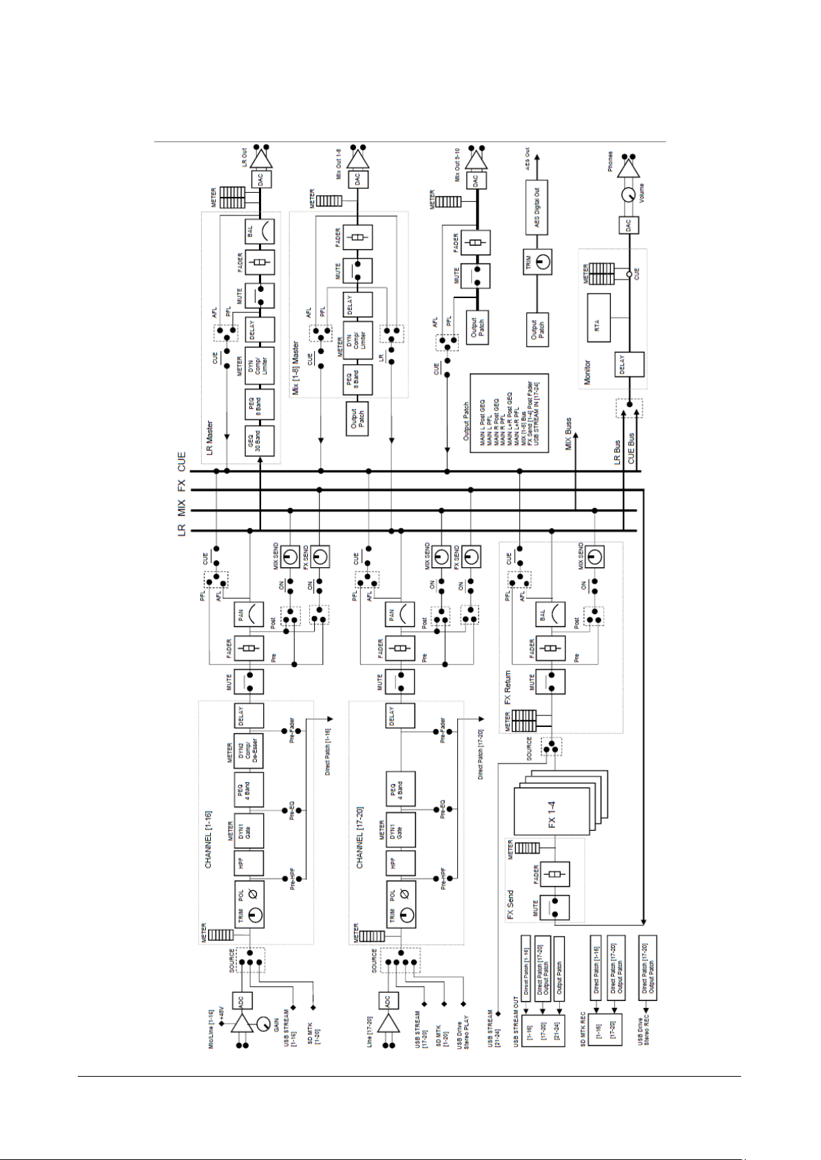
RCF spa
M 20X Digital Mixer User’s Manual
60
8. BLOCK DIAGRAM
 Loading...