

Page 1
RCF S.p.A. M 18 Digital Mixer User’s Manual 1
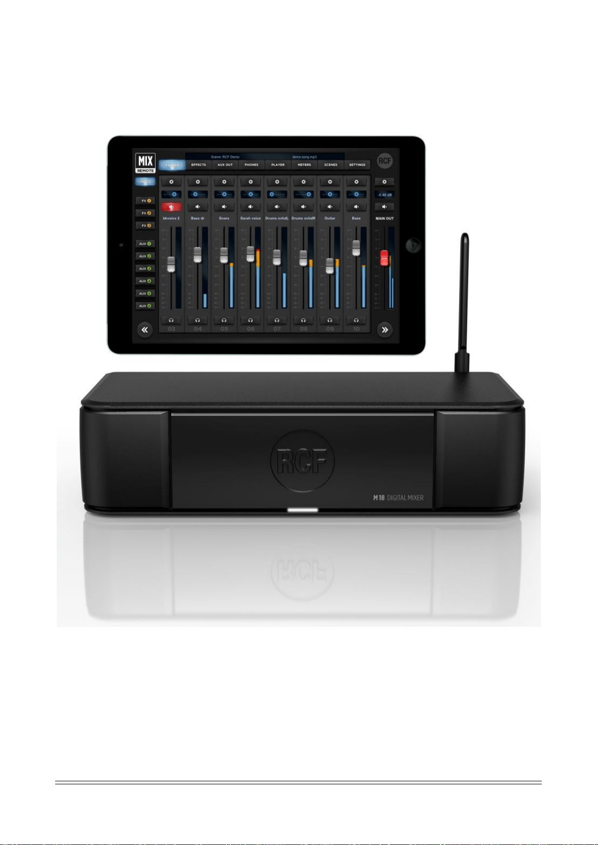
M 18 Digital Mixer - User’s Manual
Firmware Version 03.02.230 (230)
iOS MixRemote App Version 2.0.3 build 166
Android MixRemote App Version 2.2.1 build 55
Page 2

RCF S.p.A. M 18 Digital Mixer User’s Manual 2
Sommario
1. Introduction ................................................................................................................................................................ 4
2. Overview ..................................................................................................................................................................... 5
Hardware Description ..................................................................................................................................................... 5
System Overview ............................................................................................................................................................ 7
3. FIRMWARE UPDATE .................................................................................................................................................... 9
FIRMWARE UPDATE PROCEDURE ................................................................................................................................... 9
BACKUP FUNCTION PROCEDURE .................................................................................................................................. 10
RESTORE FUNCTION PROCEDURE ................................................................................................................................. 10
4. NETWORK CONNECTIONS......................................................................................................................................... 11
INTERNAL WiFi .............................................................................................................................................................. 11
EXTERNAL WIFI ROUTER ............................................................................................................................................... 13
USB TETHERING ............................................................................................................................................................ 15
5. MixRemote App ........................................................................................................................................................ 16
FADERS .......................................................................................................................................................................... 17
INPUTS View ............................................................................................................................................................. 17
Input Channel: PRE-DYN, MULTI FX .......................................................................................................................... 19
Inputs 09-10 .............................................................................................................................................................. 22
Inputs 11-18 .............................................................................................................................................................. 26
Stereo Player (from USB flash drive) ........................................................................................................................ 26
Input PEQ .................................................................................................................................................................. 26
Channel View ............................................................................................................................................................ 28
EFFECTS ......................................................................................................................................................................... 30
SEND FX ..................................................................................................................................................................... 30
MULTIFX .................................................................................................................................................................... 33
OUTPUT ........................................................................................................................................................................ 34
AUX PEQ .................................................................................................................................................................... 34
MAIN OUT Processing ............................................................................................................................................... 35
PHONES ......................................................................................................................................................................... 37
PLAY/REC ...................................................................................................................................................................... 38
PLAY .......................................................................................................................................................................... 38
REC ............................................................................................................................................................................ 40
METRONOME............................................................................................................................................................ 42
METERS ......................................................................................................................................................................... 43
LOAD/SAVE ................................................................................................................................................................... 43
SNAPSHOTS ............................................................................................................................................................... 47
SHOWS ...................................................................................................................................................................... 48
PATCHES ................................................................................................................................................................... 48
SETTINGS ....................................................................................................................................................................... 49
Page 3

RCF S.p.A. M 18 Digital Mixer User’s Manual 3
GLOBAL ..................................................................................................................................................................... 49
SYSTEM ..................................................................................................................................................................... 55
NETWORK ................................................................................................................................................................. 56
INFO .......................................................................................................................................................................... 57
6. M 18 Usage ............................................................................................................................................................... 58
Secret of mixing on a digital console ............................................................................................................................ 58
Sound Shaping with M 18 ............................................................................................................................................. 59
DRUMS .......................................................................................................................................................................... 59
BASS .............................................................................................................................................................................. 61
KEYBOARDS ................................................................................................................................................................... 61
ELECTRIC GUITARS ........................................................................................................................................................ 61
ACOUSTIC GUITARS ...................................................................................................................................................... 62
VOICE ............................................................................................................................................................................ 62
7. DECLARATION ........................................................................................................................................................... 63
8. Startup Sequence & Recovery .................................................................................................................................. 66
Restoring the unit with firmware ver. 182 ............................................................................................................... 67
Restoring the unit with firmware ver. 203 (or higher) ........................................................................................... 68
9. MIDI Implementation Chart ...................................................................................................................................... 69
10. BLOCK DIAGRAM ................................................................................................................................................. 71
11. Technical Specifications ....................................................................................................................................... 73
Page 4
RCF S.p.A. M 18 Digital Mixer User’s Manual 4
1. Introduction
A new family of compact Digital Mixers have been designed by RCF, with the aim to address the requirements
of modern performing musicians.
The main goal is to allow the user to minimize the amount of equipment needed for a live act. Therefore, a
significant effort has been spent to include all the main features to ensure a seamless performance. These
features are the following:
• compact size: the mixer is small and can be placed anywhere within the stage or between the
instruments
• full remote control over WiFi of all features
• integration of high-quality amplifier modeling
• internal WiFi Access Point and Power Supply
The M series of Digital Mixers are ideal in all cases where a dedicated sound engineer may not be available,
and therefore a FOH mixer would be inappropriate. The musicians themselves can perform the sound check
by moving in from of the house PA with a tablet and setting up the mixer accordingly.
Two independent amplifier simulation algorithms, licensed from Overloud™, have been included into a
multieffect-like organization of internal effects. This enables a further option to avoid bringing on the stage
bulky and large amplifiers, relying on the main PA and stage monitors.
A high-quality stereo player is available on the unit, accessing files from a USB flash drive, representing a further
option in minimizing the amount of equipment required for a live gig.
Therefore, you can leave home several items, such as the multicore snake, external effects that would normally
connect to the mixer, guitar and/or bass amplifiers, external file players, and yet obtain a high-quality and
professional result.
Page 5
RCF S.p.A. M 18 Digital Mixer User’s Manual 5
2. Overview
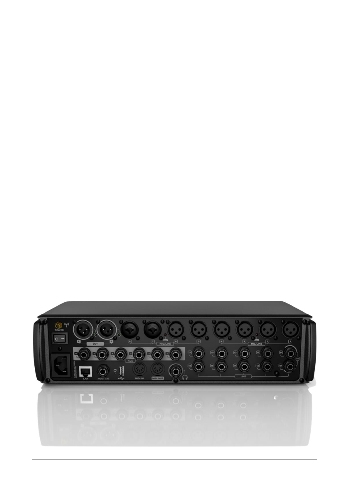
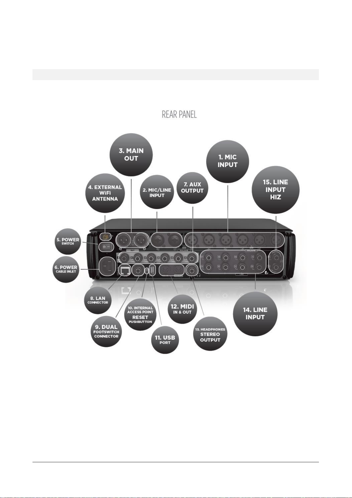
Hardware Description
All connectors are available on the rear panel, for maximum compactness.
1. MIC Input 1 to 6 – XLR Female
Connect your Microphones to these remotely-controlled 60dB gain-range inputs. Red LEDs indicate
the Phantom power status ON or OFF for MIC input groups 1 to 4 and 5 to 8. To obtain best
performances from your microphones, use balanced XLR cables.
2. MIC/LINE Input 7 and 8 – Combos
Input 7 & 8 provide Mic input on the XLR connection and Line input on the TRS jack connection.
3. MAIN OUTPUT L&R
Connect your active speaker or your amplifier to these +21dBu balanced Output. The green LEDs
show the signal presence on MAIN MIX channels independently for LEFT and RIGHT outputs.
Page 6
RCF S.p.A. M 18 Digital Mixer User’s Manual 6
4. External Wi-Fi Antenna connector
M 18 includes an internal antenna and provisions for an external antenna. Attach the provided
external antenna to this connector for optimal performance of the MixRemote app.
[please refer to Statement for Detachable Antenna in Appendix A/1]
5. Power switch
Turn On and Off your M 18 device.
6. Power cable inlet.
Connect here the provided power cord.
7. AUX Output 1-6 Balanced jacks
Connect to these +21dBu balanced output your stage monitors or external effects.
8. LAN connector
It is possible to connect here an external Wi-Fi Access Point for advanced communication
configurations. This port is intended also for future applications.
9. Dual footswitch connector
Connect here a single or dual external footswitch. The footswitch port allows connection of a single
or double stage footswitch to recall effects’ presets or to mute effects’ returns, as well as providing
several other control functions.
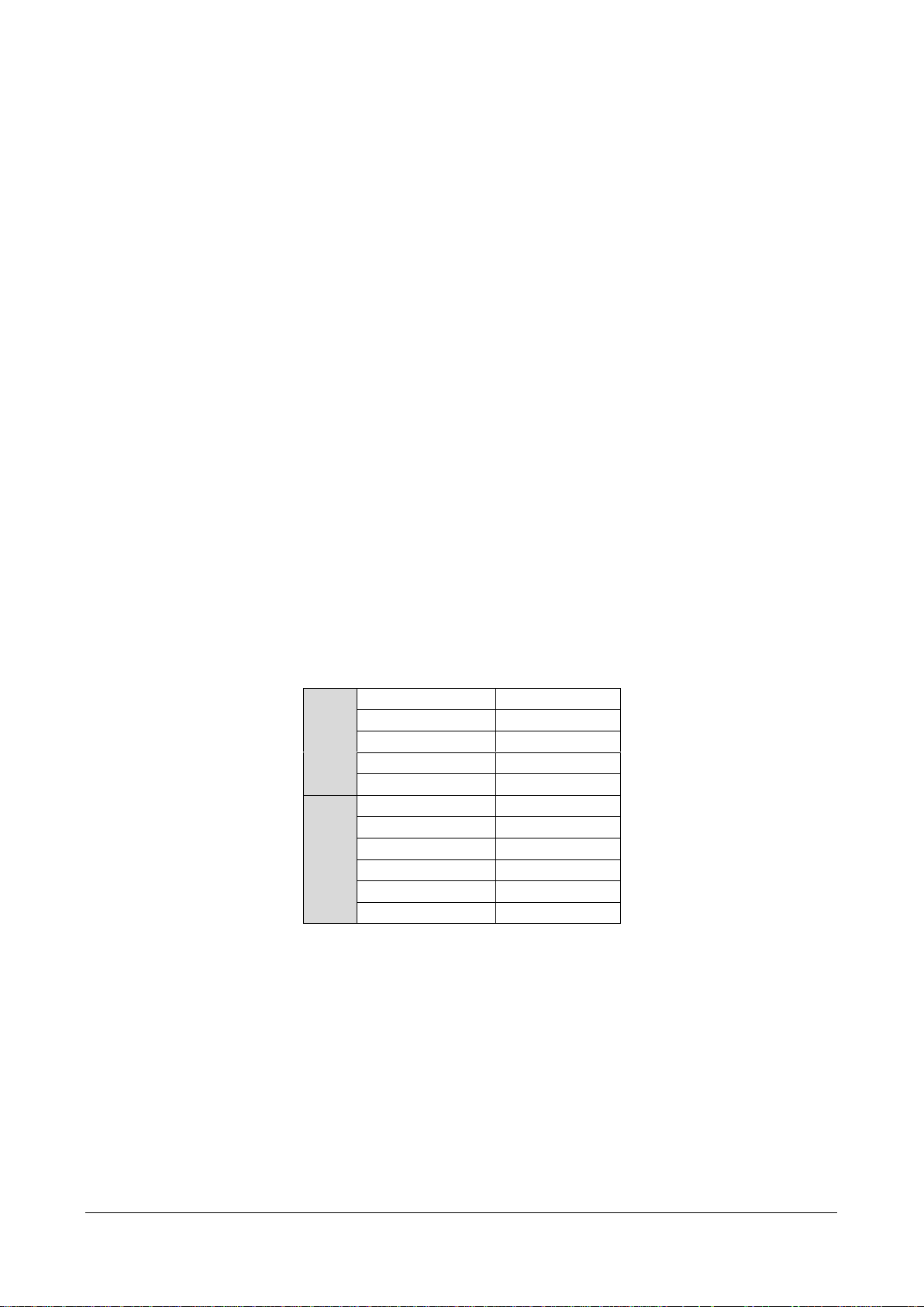
10. Internal access point reset pushbutton
Press this button during normal operation (for less than 10 seconds) to restore the default settings
for both the internal Wi-Fi Access Point and the LAN port, as follows:
LAN
IP configuration
Static
IP address
192.168.0.18
Netmask
255.255.255.0
Gateway
0.0.0.0
DNS
0.0.0.0
WiFi
Band
2.4 GHz
Country
NONE
Channel
3
Security
OPEN
SSID
M18-xxxxxx
External Antenna
Enabled
This button is available also for other functions, you can review them more in detail at page 67.
You can modify these settings from the MixRemote app in the SETTINGS > NETWORK page.
11. USB Type A port
Insert here a USB stick to play high quality audio files. .WAV, .AIFF and MP3 file allowed for
reproduction.
12. MIDI connectors
Connect here your MIDI controller. See the dedicated page on MixRemote (SETTINGS > MIDI) to
view the assigned MIDI channels for specific functions.
Page 7
RCF S.p.A. M 18 Digital Mixer User’s Manual 7
13. Headphones stereo output
Connect your headphones here either for PFL, Personal Monitoring or the Main Mix listening.
14. LINE Input 11-18
Connect here your line level sources like keyboard, external audio device or other small analog
consoles used for submix. These input are unbalanced, and their operating levels can be set to
+4dBu or -10dBV.
15. LINE Input 9-10 with switchable HiZ input
Connect to these unbalanced inputs your line-level sources, at +4 dBu or -10 dBV, or highimpedance passive instruments, like electric guitars, electric basses or piezo pickups. You can
individually enable the Hi-Z option, that offers a 1 Mohm input impedance when activated.
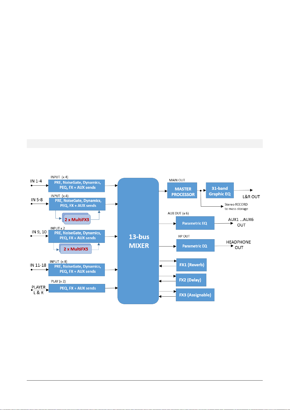
System Overview
The M 18 Digital Mixer is a feature-packed unit that includes several of the useful blocks required to arrange a
good-sounding live act.
Signal processing capabilities of the M 18 Digital Mixer
In addition to the usual essential processing blocks that are present in every mixer (equalizers, compressors),
several effects are available, arranged as follows:
• Three global stereo effects, each with a dedicated FX SEND buss
• Two 5-stage MultiFX blocks, dedicated to channels 9 and 10; in each of these two blocks, an amp
simulator is available
• Two 3-stage MultiFX blocks, dedicated to channels 5 and 6 or 9 and 10
• A highly musical Mastering Processor on the MAIN L & R output signals
Page 8
RCF S.p.A. M 18 Digital Mixer User’s Manual 8
• A 31-band stereo Graphic Equalizer on the MAIN L& R output signals, after the Mastering Processor
The MultiFX blocks can be managed independently from the mixer, with a set of memories (which we call
PATCHES), to allow the same flexibility which would be available with an external multieffect unit.
A total of 13 summing busses are present in the M 18 Digital Mixer:
• MAIN left & right buss
• FX SEND 1,2,3 buss
• AUX SEND 1,2,3,4,5,6 buss
• Stereo PHONES buss
Among these, the stereo personal monitor deserves special mention.
You can set the PHONES buss in one of two modes:
• PFL mode (pre-fader listen), in which the input channels put in SOLO mode are summed and sent
to the PHONES output, through the EQ and PHONES fader; the PFL level is shown on the MAIN L
and R VU meter. Please notice that the stereo PFL VU meter display reflects the PAN value, and of
course, being pre-fader, is not affected by the fader level.
• Personal Mix mode, in which a separate mix of all inputs, including the 2-channel player, is
available and allows a complete stereo mix to be routed to the PHONES output (and optionally to
a pair of AUX outputs; see routing options)
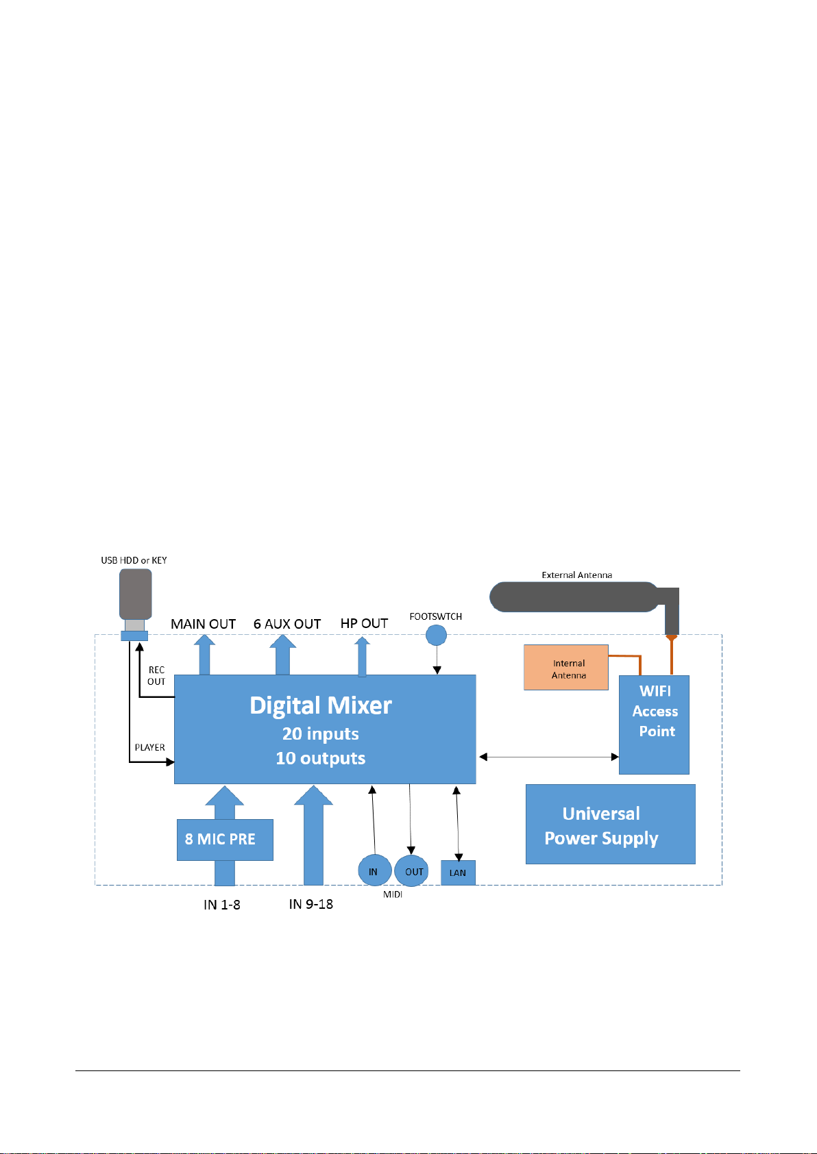
A complete overview of the M 18 internal features is shown here below:
The internal Access Point is a dual-antenna MIMO WiFi interface; one of the two antennas is external, while the
other is located on the top right side (when facing at the RCF logo).
Page 9
RCF S.p.A. M 18 Digital Mixer User’s Manual 9
3. FIRMWARE UPDATE
MixUpdate is a dedicated application for M 18 firmware update. MixUpdate for iOS also features BACKUP
and RESTORE functions. BACKUP allows saving all the Snapshots, Shows and Effects’ Patches from the mixer
into a USB stick inserted in the M 18. Then, the RESTORE command brings the contents back to the M 18,
either the same unit or a different one.
FIRMWARE UPDATE PROCEDURE
1. Install the RCF app MixUpdate on your iPad or Android tablet. You can find MixUpdate on the App
Store and Play store.
2. Download the latest firmware file available on the web page
https://www.rcf.it/products/mixing-consoles/m-series/m-18-firmware-update
3. Unzip the .zip file and copy the
RCF-M18_0XXX.mpk
file on the root directory of a FAT32 formatted
USB stick. Be sure to have one
.mpk
file only in the USB stick, to avoid file mismatch.
4. Insert your USB stick into the M 18 USB slot and turn it on.
5. Connect the tablet to the M-18XXXXXX network through WiFi settings.
6. Launch the MixUpdate app and click on "Connect".
7. The left column shows the firmware version that is currently installed on M 18. The right column
shows the firmware version on the USB stick, ready to be installed.
8. Click on the Update button to install the most recent version and press OK to proceed
9. After a few seconds you will see a confirmation notice
10. Press the OK button to reboot the M 18. This procedure will take a few seconds.
11. After rebooting the following notice will appear:
Go back to your iPad’s WiFi configuration page and check the network connection.
Make sure you are connected to the M18-XXXXXX network.
12. Launch the MixRemote App again and enjoy the updated M 18 mixer.
Page 10
RCF S.p.A. M 18 Digital Mixer User’s Manual 10
You may need to perform a two-step firmware update, depending on firmware version currently installed on
your M18 unit. If you current firmware version is 187 or earlier, please update to version 221 first. Then, after
power cycling the unit, you can perform the desired firmware update to the latest version. Here is a summary
of required actions, depending on your current firmware version:
• 177 → update to 221 first → update to the latest version
• 182 → update to 221 first → update to the latest version
• 203 or later → update to the latest version
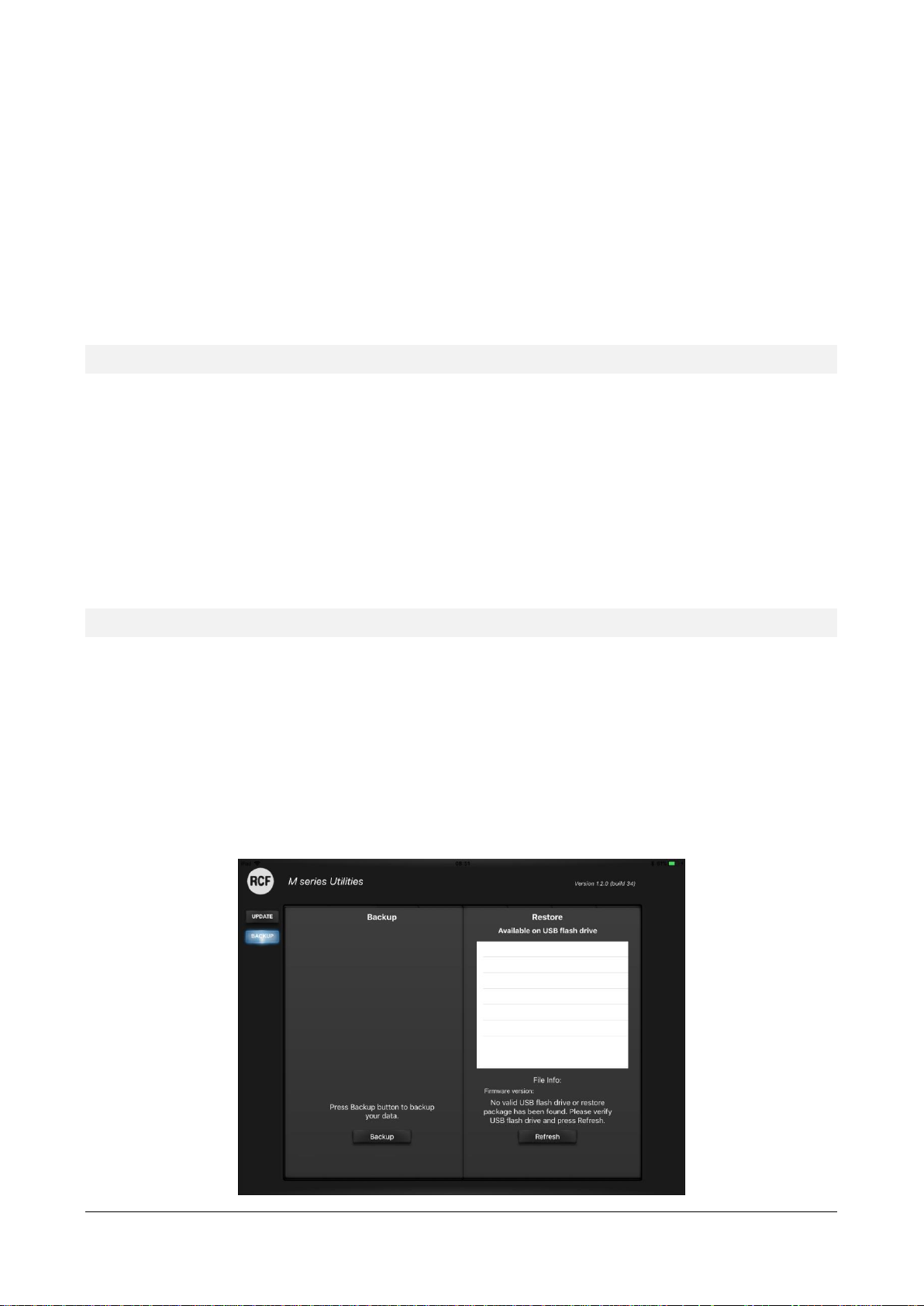
For iOS version only, a Backup & Restore page is available on the MixUpdate app
BACKUP FUNCTION PROCEDURE
1. Connect to the M-18XXXXXX network through the WiFi settings in the Configuration menu of your
tablet
2. Launch the MixUpdate app and click on "Connect"
3. Insert your USB stick into the M 18 USB slot
4. Touch the BACKUP tab on the left
5. Press the Backup button in the left column of the screen
6. A notice will appear, click on “OK” to proceed
7. A complete backup has been successfully created on the USB stick
RESTORE FUNCTION PROCEDURE
1. Connect to the M-18XXXXXX network through the WiFi settings in the Configuration menu of your
tablet
2. Launch the MixUpdate app and click on "Connect"
3. Insert the USB stick containing the M 18 backup into the M 18 USB slot
4. Touch the BACKUP tab on the left
5. Press the Restore button on the right column
6. If you want to proceed, click on “OK”
7. The restore procedure has been completed
Page 11
RCF S.p.A. M 18 Digital Mixer User’s Manual 11
4. NETWORK CONNECTIONS
There are several options to connect with the Digital Mixer:
• Wireless via the internal WiFi Access Point
• Wireless via an external WiFi Access Point connected to the LAN
• USB tehering to an Android tablet
INTERNAL WiFi
The M18 is equipped with an internal Wi-Fi double antenna supporting dual band connection (2,4 GHz and 5
GHz). If the M Mixer is rack installed or used in a demanding environment, an improvement of Wi-Fi connection
is possible thanks to the provided external antenna.
When connecting an M 18 Digital Mixer to your tablet for the first time:
1. On your tablet open the Wifi Settings
2. A Wi-Fi network with SSID called M 18-xxxxxx will appear in the available network list (xxxxxx is an
alphanumeric string related to the internal MAC address).
3. Select the M 18 Wi-Fi network.
4. No password is requested by default.
5. Wait for the connection (typically five to ten seconds).
6. Now, launch the MixRemote application, select Wi-Fi option and press Connect
7. If MixRemote app is already open in background, M 18 will be connected as soon as the application
is moved to foreground.
Please notice that if you have modified the Wi-Fi settings (SSID name, password, etc..) the connection
procedure may vary.
Page 12
RCF S.p.A. M 18 Digital Mixer User’s Manual 12
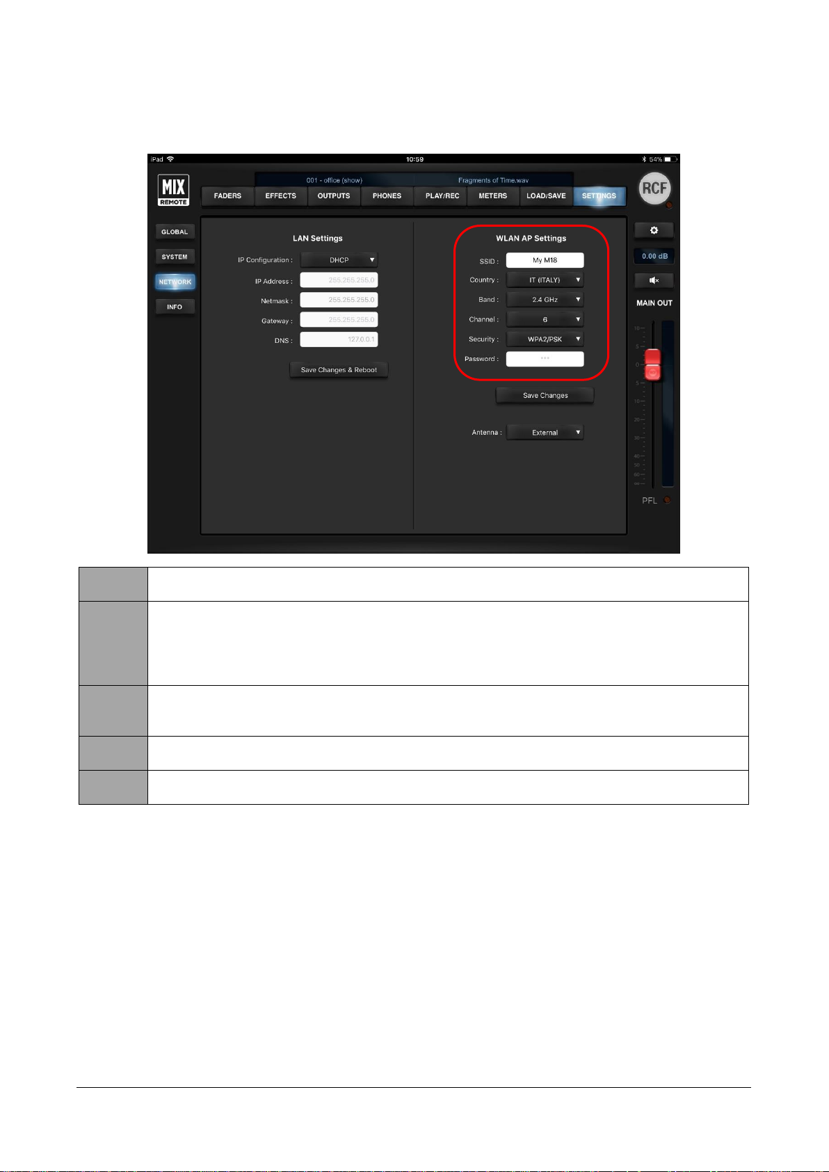
We recommend to configure the WLAN AP Settings using the SETTINGS/NETWORK page of MixRemote app:
After you perform all changes to WLAN parameters, you must press Save Changes to modify these settings
into the mixer.
IMPORTANT: to obtain best WiFi connection performance, avoid placing any object over the M 18 top
cover, as it will obstruct the internal antenna, reducing Wi-Fi connection range and reliability. Always connect
the provided external antenna and select your country on MixRemote App. SETTINGS > NETWORK section.
Failing to select the country will result in degraded WiFi performance.
SSID
You can modify the factory setting to provide a name you can remember. The factory name is in the form
M18-XXXXXX where the latter are a combination of letters and numbers.
Country
By selecting the appropriate country where you are operating the mixer, you can comply with local radio
regulations. Please notice that if you leave to the default value NONE, transmitting power is limited and
you will not obtain the best performance from the M 18 Digital Mixer, including maximum distance and
robustness to interference
(feature not allowed on USA/Canada software version)
Band
You can select between the usual 2.4 GHz band and the less crowded 5 GHz band, depending on your tablet
capabilities. For USA and Canada markets, the 5 GHz band is not allowed, according to the local FCC/IC
regulations.
Channel
You can minimize interference from other Access Points by selecting a channel not being used by others.
There are several scanning software applications that enable you to view which channels are available.
Security
You can either keep the Access Point open, or enable WiFi security (WPA2/PSK). In this case, you will be
able to modify the default password.
Page 13

RCF S.p.A. M 18 Digital Mixer User’s Manual 13
EXTERNAL WIFI ROUTER
It is possible to use an external WiFi router connected to the M 18 Digital Mixer via the internal 1 Gbit LAN
port. This capability is available for both iOS and Android devices. Two options are available on the M 18: by
setting a static IP or enabling the DHCP client.
METHOD 1 – STATIC IP
1. Use a Wireless Router with DHCP Server Enabled and take note of its IP Address (in this document
we will assume 192.168.10.99).
2. Connect the M 18 to the Wireless Router with a Cat5E cable.
3. Connect the tablet to the M 18 internal WiFi, launch MixRemote and connect to the M 18 using the
standard method (WiFi).
4. Go to the SETTINGS / NETWORK page, select <Static> in the IP configuration and type an address in
the same subnet of our Router (ie. 192.168.10.80) with the default NetMask (255.255.255.0) and the
Router IP Address in the Gateway and DNS field (In our case 192.168.10.99):
5. Press Save Changes & Reboot to save these modifications on the M 18.
6. Connect the Tablet to the Wireless Router WiFi network.
Page 14
RCF S.p.A. M 18 Digital Mixer User’s Manual 14
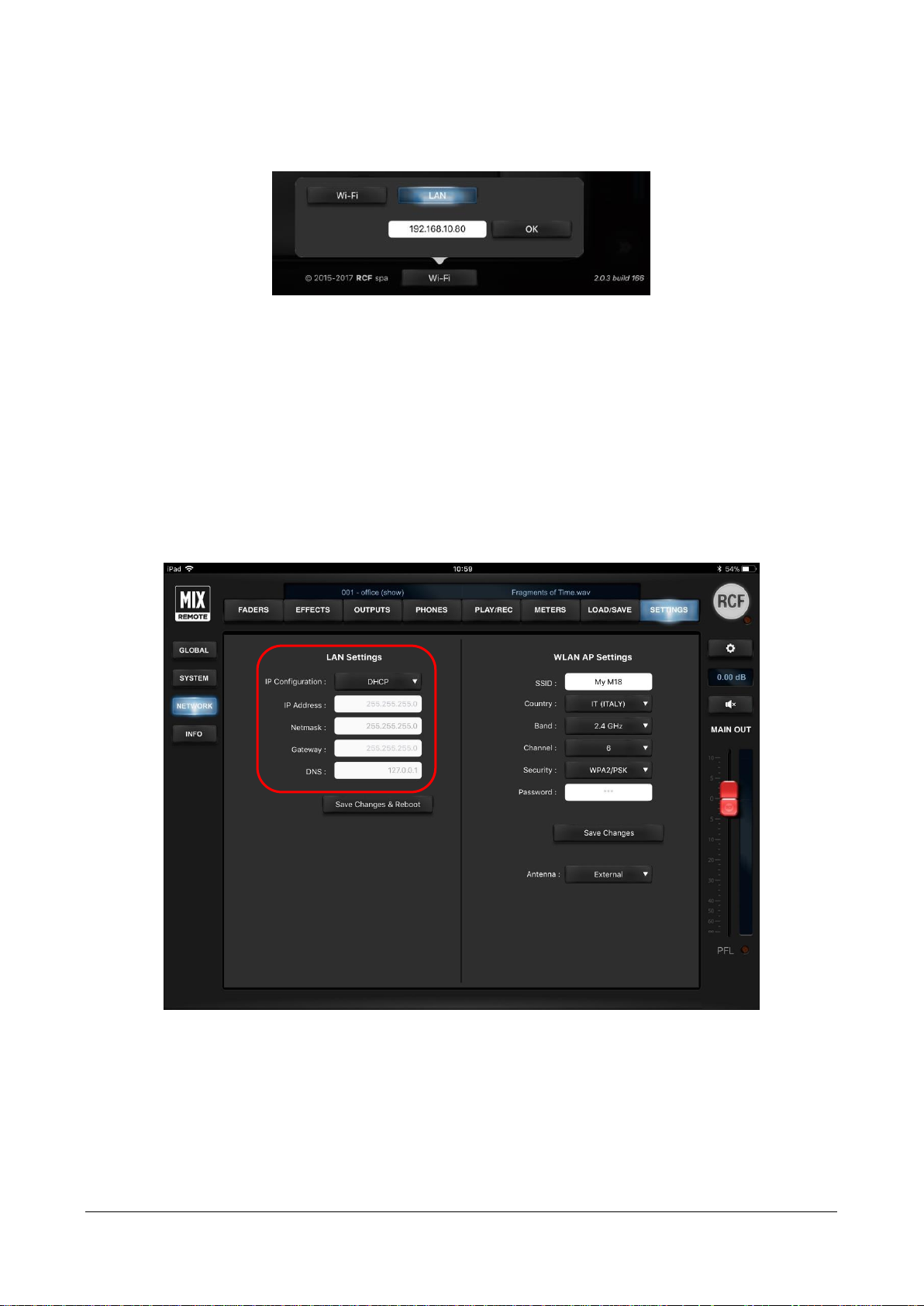
7. Launch the MixRemote App; on the welcome page, select LAN in the bottom part of the software
interface andtype the static IP address previously assigned to the M 18 (192.168.10.80), then press
OK
8. If connection fails, it may be due to the fact that the selected IP address is already assigned to
another device; in this case, repeat from step 3 and type a different static address.
9. Press CONNECT; the app is now connected to the M 18 Digital Mixer via the external WiFi Router
METHOD 2 – DHCP
1. Use a Wireless Router with DHCP Server Enabled and take note of its IP Address (in this document
we will assume 192.168.10.99).
2. Connect the M 18 to the Wireless Router with a Cat5E cable.
3. Connect the tablet to the M18 internal WiFi, launch MixRemote and connect to the M 18 using the
standard method (WiFi).
4. Go to the SETTINGS / NETWORK page, select <DHCP> in the IP configuration:
5. Press Save Changes & Reboot to save these modifications on the M 18.
6. After the reboot, reconnect the tablet to the M 18 internal WiFi, launch MixRemote and connect to
the M 18 using the standard method (WiFi).
7. Go to the SETTINGS / NETWORK page and take note of the IP address assigned to the M 18 by the
external WiFi Router; quit the MixRemote App.
8. Connect the Tablet to the Wireless Router WiFi network.
9. Launch the MixRemote App; on the welcome page, select LAN in the bottom part of the software
interface and type the IP address found in step 7.
Page 15

RCF S.p.A. M 18 Digital Mixer User’s Manual 15
10. Press CONNECT; the app is now connected to the M 18 Digital Mixer via the external WiFi Router
Note: We suggest to work with a static IP Address (Method 1) to always identify the M 18 in your network.
Using the DHCP (Method 2), it may happen that the IP address previously given to the M 18 is assigned to
another device. In that case you have to repeat the steps of the DHCP Method from number 6.
USB TETHERING
The M 18 Digital Mixer can be directly connected to a Samsung device (both tablets and smartphones) via a
wired USB connection. These feature is available only on the MixRemote app for Android.
Please follows these steps to enable the connection every time you connect the Samsung device:
1. Connect the USB cable between the M 18 and the Samsung device
2. Launch the MixRemote app on the Samsung device
3. In the lower part of the welcome screen, select USB TETHERING
4. When you press OK, the app redirects you to the Settings page of the Samsung device where you
can enable USB Tethering:
Please notice that this page differs from model to model
5. Press the BACK button (or icon) on your Samsung device, that allows you to return back to the
MixRemote app to the Welcome screen
6. Press CONNECT; the app is now connected via wire to the M 18 Digital Mixer
Page 16
RCF S.p.A. M 18 Digital Mixer User’s Manual 16
5. MixRemote App
The MixRemote app ensures a comprehensive control of M Series mixer. Featuring attractive and intuitive
graphics created by audio professionals, the app allows you to navigate between pages and fully control
all mixer parameters while playing. The MixRemote app is available for iOS and Android operating systems.
Several enhancements are periodically added to the app, therefore we suggest to check periodically for updates
on iTunes and Play Stores. Before downloading an updated app, please verify on the release notes if it is required
to upgrade the hardware unit via a firmware update before using the updated app.
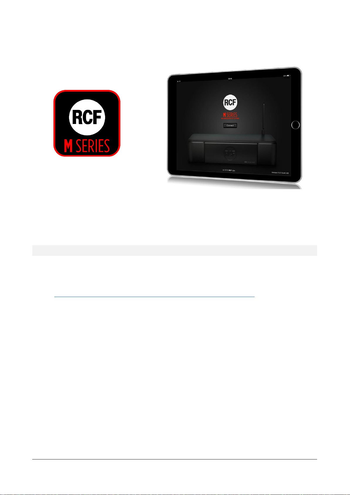
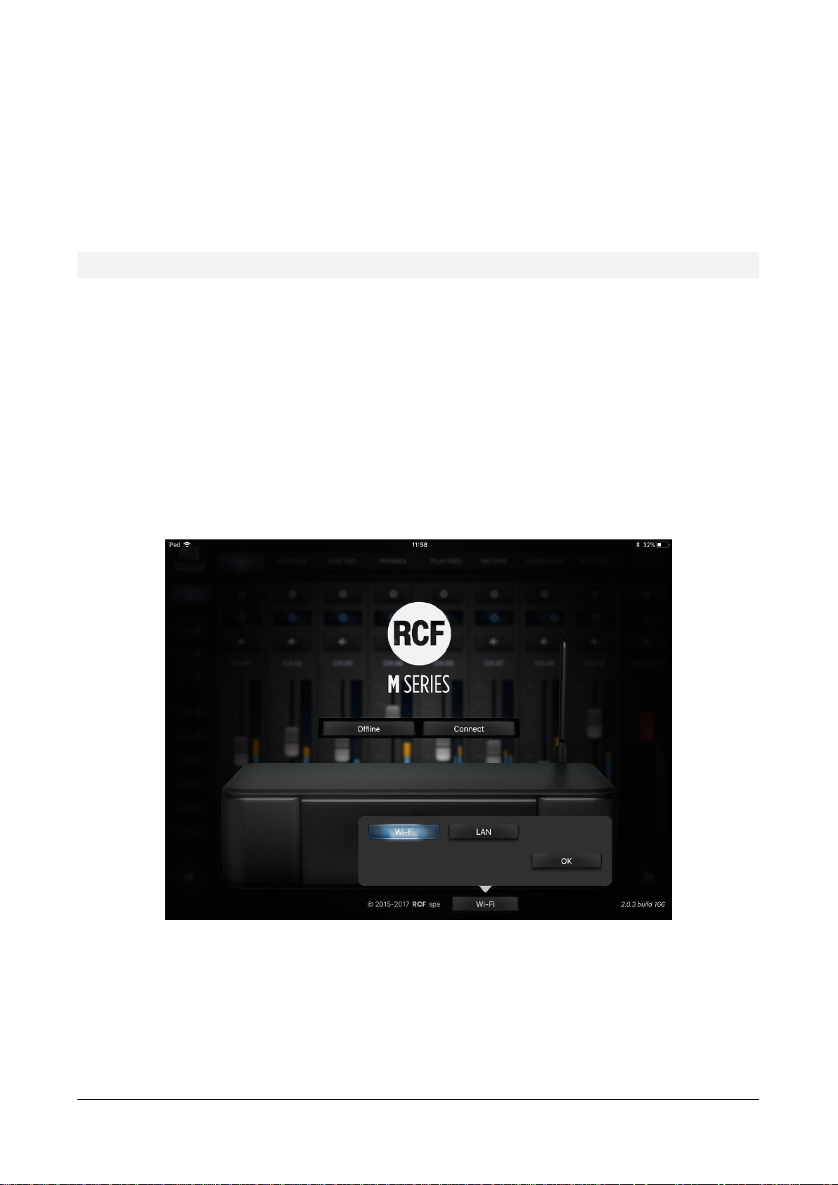
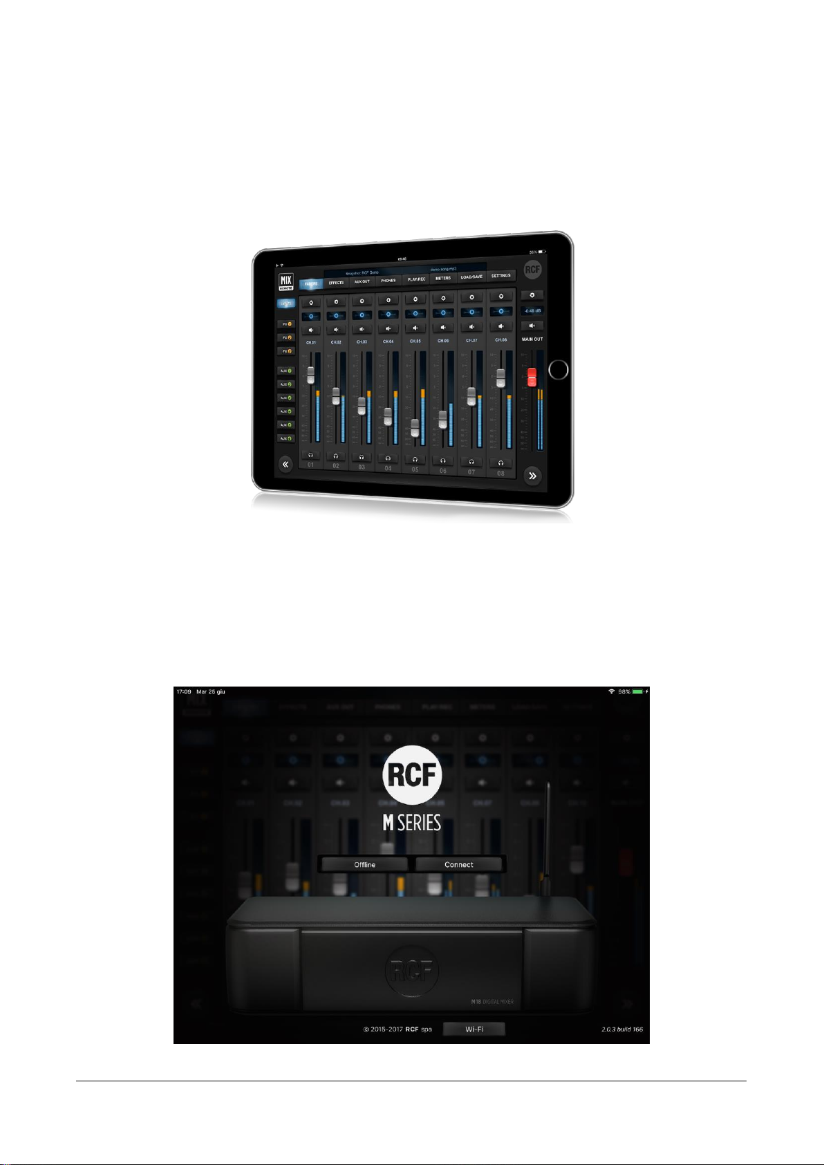
When you first launch the app, a welcome screen is shown; at this point, you are still not connected to the
mixer.
Welcome screen
Page 17

RCF S.p.A. M 18 Digital Mixer User’s Manual 17
In this view, you can choose between the following:
Offline: you can browse all features of the app without the need to connect to a physical M 18 unit
Connect: the mixer connects to your control device in few seconds, provided that you have selected
the proper mixer WiFi Access Point
On the bottom row, you can modify the IP address of the target mixer; there is a button to recall the default
value intended for the internal WiFi Access Point
(only available on MixRemote ver 1.1.0 or newer)
.
After pressing Connect, you are directed to the real operative views of MixRemote.
FADERS
INPUTS View
The first page you access is the FADERS INPUTS page, which shows on the top left the MIX REMOTE logo (1).
It you tap on the MIX REMOTE logo, you will be directed to the main FADERS > INPUTS view; this is a sort of
“Home” button that leads you always to the initial page with input faders.
In the central area, on the upper side, there is a small text box with indications of the currently active session
(2). Below there is a row of main tabs, named from left to right FADERS (4), EFFECTS (5), OUTPUTS (6), PHONES
(7), PLAY/REC (8), METERS (9), LOAD/SAVE (10) and SETTINGS (11); the active tab is backlit. On the right side
there's the RCF logo (3), which is lit (in brilliant white) when your controller is connected to the M 18 Digital
1 2 3 4 5 6 7 8 9
10
11
12
13
19
20
21
22
14
15
16
17
18
Page 18
RCF S.p.A. M 18 Digital Mixer User’s Manual 18
Mixer. A small indicator just below the logo signals lights up to indicate that the M 18 Digital Mixer is busy and
the app is waiting for a response.
The fader caps are color coded consistently throughout the app:
SILVER caps
Input faders; Monitor output faders; FX buss master faders
ORANGE caps
FX send faders, for each input channel
GREEN caps
AUX send faders, for each input channel
RED cap
MAIN output fader
The FADERS page, as most pages, is divided in three areas.
The left area, under the MIX REMOTE logo, enables the recall of the INPUTS tab, which is the default one.
Below, there are FX1, FX2, and FX3 tabs in orange, as well as AUX1, AUX2, AUX3, AUX4, AUX5, and AUX6
tabs in green. At the bottom there is a double arrow allowing you to scroll down 8 inputs at a time, or more if
some channel are stereo linked.
The right column, under the RCF logo, is dedicated to the MAIN OUT section, featuring the * key (19) to recall
the MAIN settings page, a box (20) indicating the level of the stereo fader in dB, the Mute button (21), the
MAIN OUT text box and the red stereo fader (22), which remains active in almost every page of the mixer. At
the bottom there is a double arrow allowing you to scroll up 8 inputs at a time, or more if some channel are
stereo linked.
The central area is reserved for a view of 8 faders (12);
this area can be scrolled by swiping your finger
horizontally. Above each fader there is a * (13) to recall
its setup pages, a box indicating the pan-pot position or
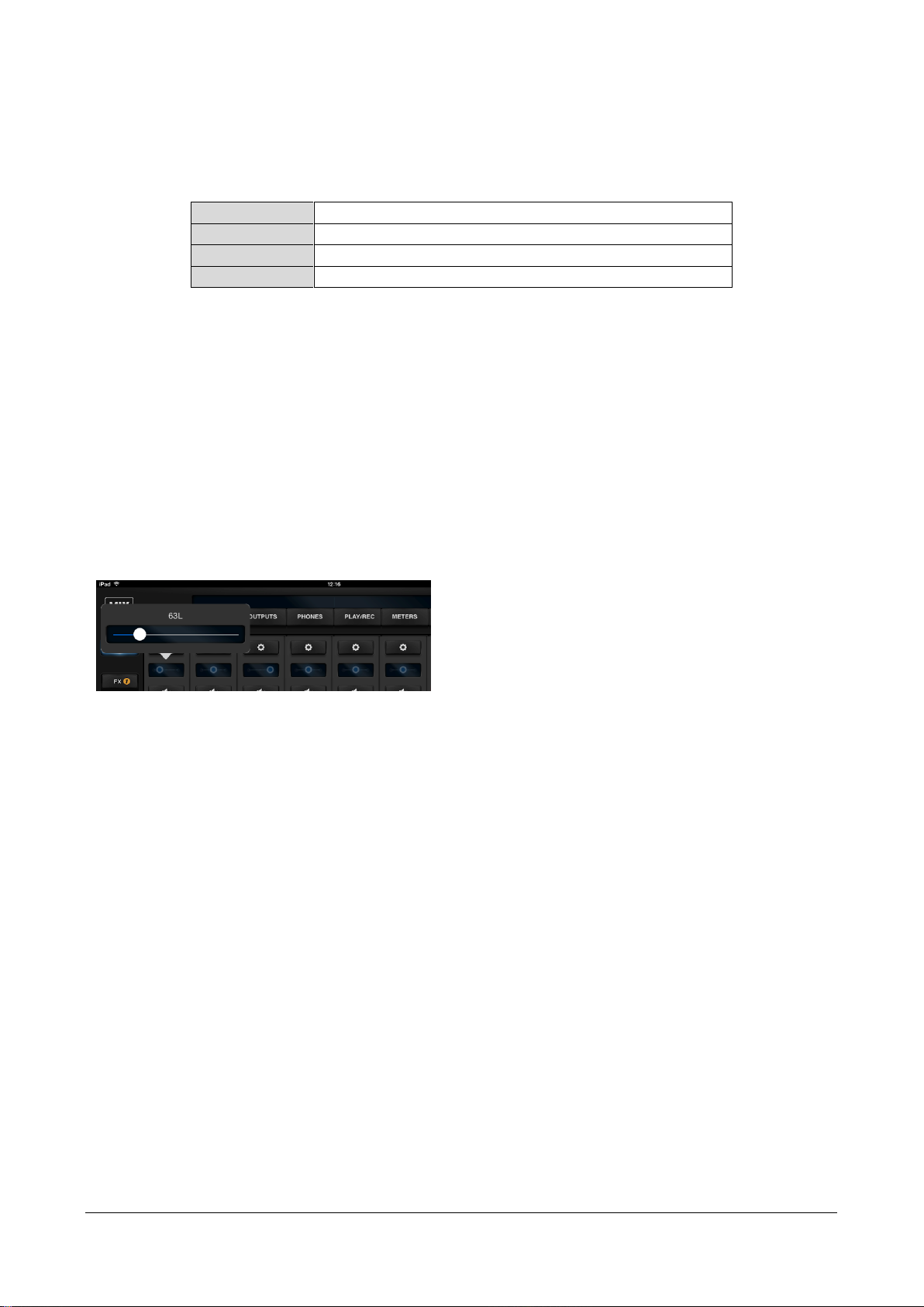
each fader level in dB (14) and a Mute button (15).
Please note that clicking on the pan-pot, a larger
windows opens, allowing better setting accuracy.
Then there's a text box (16) which by default shows the channel number, e.g. CH.01 by clicking on the button
appears a keyboard allowing you to enter up to 12 characters to name the channel. On the right of each fader
there's the relevant level indicator, and under the fader there is the headphone icon (17) if the PFL mode is
activated – please see the Settings tab, Global page. Finally there's the number of the hardware input (18),
which can't be modified. The PFL function (Pre-Fader Listen), when enabled, redirects the level indication from
the PFL bus into the Main VU meter; a yellow LED indicates that the Main VU meter is showing the PFL level
instead of the actual audio output.
On the Main bus (INPUTS Tab) there are 27 strips available:
18 analog inputs faders, Play L and Play R faders (dedicated to signals from USB stereo player), 3 stereo FX
RTN faders for internal effects returns and 4 DCA faders to control DCA Groups.
On the FX busses (FX1, FX2, FX3 Tabs) there are 20 strips available:
18 analog inputs faders and Play L and Play R faders (dedicated to signals from USB stereo player).
On the AUX busses (AUX1, …, AUX6 Tabs) there are 23 strips available:
18 analog inputs faders, Play L and Play R faders (dedicated to signals from USB stereo player) and 3 stereo
FX RTN faders for the internal effects returns
The Play L-R channels don't have the PRE-DYN section, the FX RTN channels have only boxes for dB level,
MUTE, fixed name, and PFL, as well as the fader, and the DCA channels, in addition to fader, mute and level,
have an edit button to jump directly to DCA Group Assignment Page in the SETTINGS/GLOBAL/DCA GRP view.
Page 19
RCF S.p.A. M 18 Digital Mixer User’s Manual 19
Input Channel: PRE-DYN, MULTI FX
By clicking on the EDIT button you access each channel settings page; please note that these pages are different
for inputs 1-8, which hardware section is provided with XLR and combo connectors, allowing the use of
microphones, eventually provided of Phantom power, see SETTINGS tab GLOBAL page. Note that channels
05-08 may have the MULTI FX page - with up to three effects.
Inputs 09-10 hardware sections allows the use with a Hi-Z signals, with a specific selector in mixer channels,
and have a large MULTI FX page - with up to five effects. Channels 11-18 features line level only inputs, with
a different RCF PRE layout.
In the left column the last modified section between PRE/DYN, EQ, MULTI FX (only for channels 05-10) and
SEND is lit. The right column, shows the MAIN OUT controls.
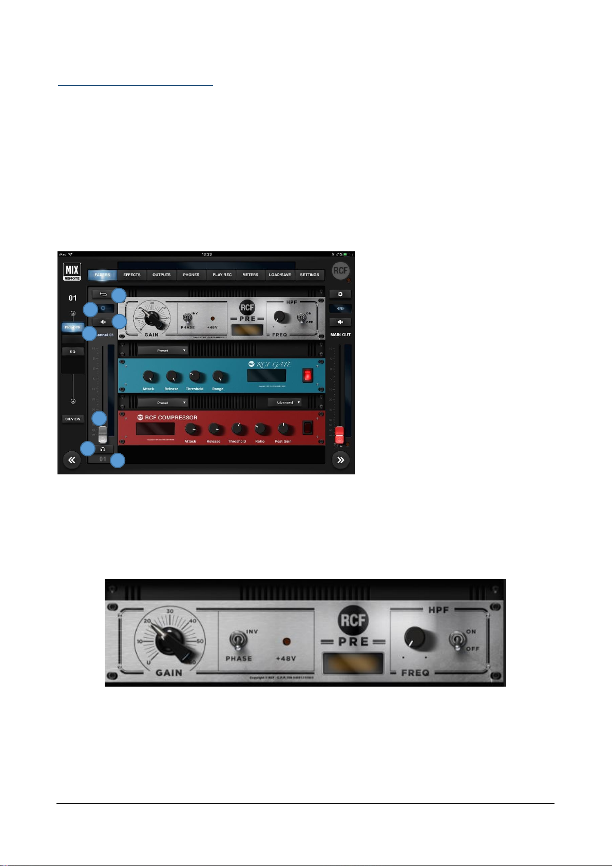
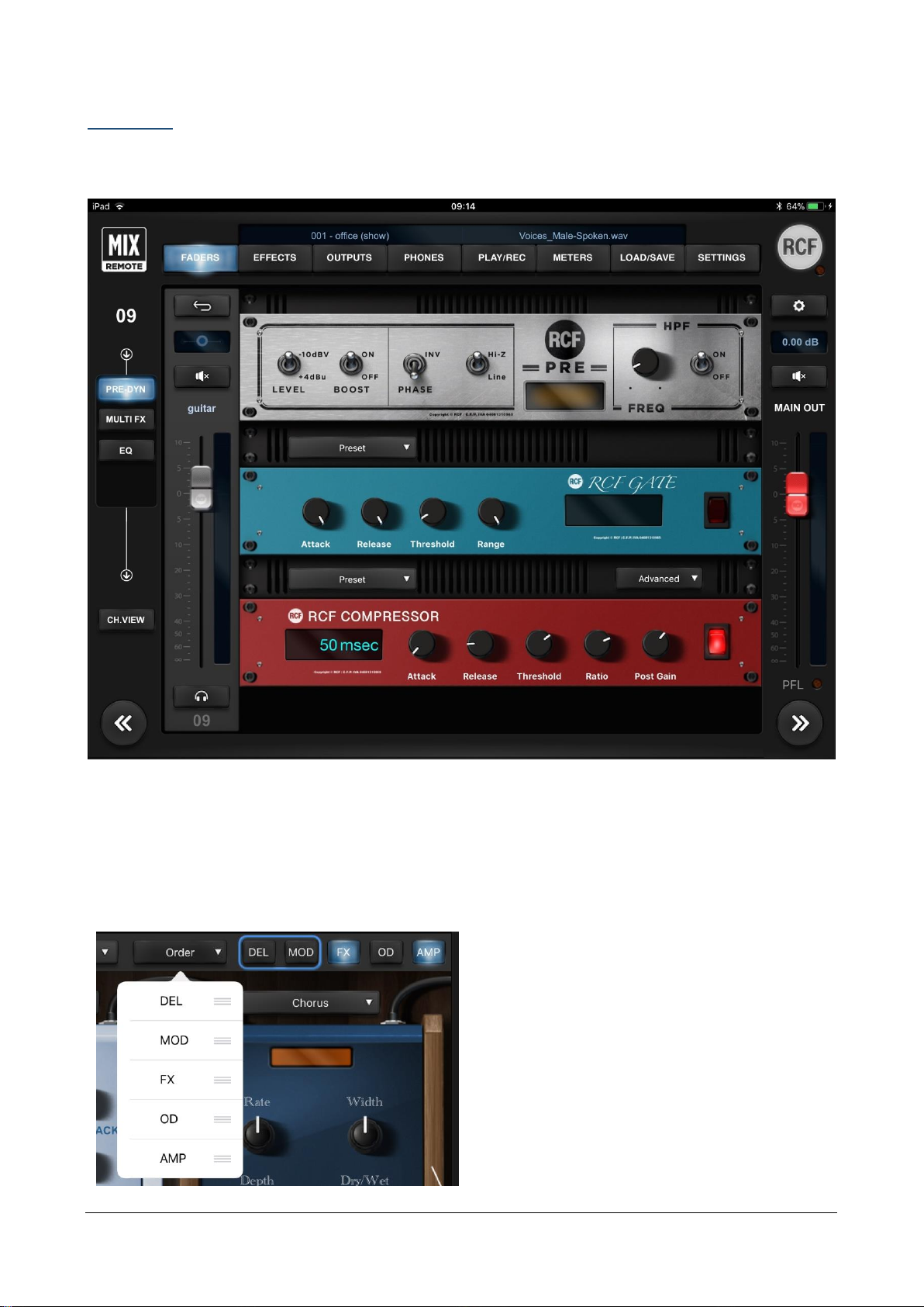
Inputs 01-08
The left part of the center column contains
on the top left a BACK button (1) to allows
you return to the INPUTS view, followed
by the pan control which also shows fader
value in dB when moved (2), the Mute (3)
button, the channel editable name (4), the
fader (5), the PFL (6) button and the noneditable number of the hardware input
(7). The larger part of this page shows a
rack containing RCF PRE, RCF GATE and
RCF COMPRESSOR, above the latter two
there is a box to recall presets.
The two large arrow buttons on bottom left and right enable you to change input channel immediately, without
requiring to go back to the INPUTS view.
The RCF PRE preamplifier features a single GAIN control (from 0 dB to 60 dB in 31 dB steps), the LED indicating
the activation of the Phantom 48V power over the INV switch (phase inversion). The display shows the values
of each parameter, including the frequency of the HPF (selectable between 10Hz and 500Hz) which is activated
via its ON button.
1 5 3
4
2 6 7
Page 20
RCF S.p.A. M 18 Digital Mixer User’s Manual 20
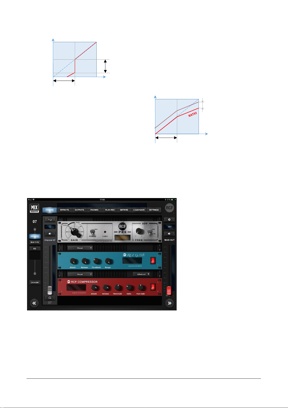
The second unit is the RCF GATE, topped by its Preset box,
with ATTACK and RELEASE time controls, THRESHOLD
level and RANGE intervention, completed by the display
and the activation switch. On the left you can see the
characteristic curve of the internal GATE: when the input
signal goes below the THRESHOLD, its level is reduced by
RANGE dBs.
The third unit is the RCF COMPRESSOR,
topped by its Preset box, with a display on the
left, followed by ATTACK and RELEASE times
controls, THRESHOLD level, RATIO
compression, POST GAIN level and the
activation switch. On the right, the
characteristic curve of the compressor is
shown, including the contribution of POST
GAIN control.
For faster adjustments, the compressor features the Easy option, located in a small box on the left of the Preset
box - Easy has only the COMPRESSION control (based on input level signal with preset thresholds, with
automatic Post Gain adjustment) against the five controls of Advanced option.
Inputs 5-6 and 7-8
The left part of the center column
contains on the top left a key (1) to
return to INPUTS followed by the level of
the individual fader in dB (2), the Mute
(3) key, the name of the channel (4), the
fader (5), the PFL (6) key and the noneditable number of the hardware input
(7). The larger part of this page shows a
rack containing RCF PRE, RCF GATE and
RCF COMPRESSOR, above the latter two
there is a box to recall presets.
0 dBFS
IN
OUT
0 dBFS
THRESHOLD
RANGE
0 dBFS
IN
OUT
0 dBFS
THRESHOLD
POST
GAIN
Page 21
RCF S.p.A. M 18 Digital Mixer User’s Manual 21
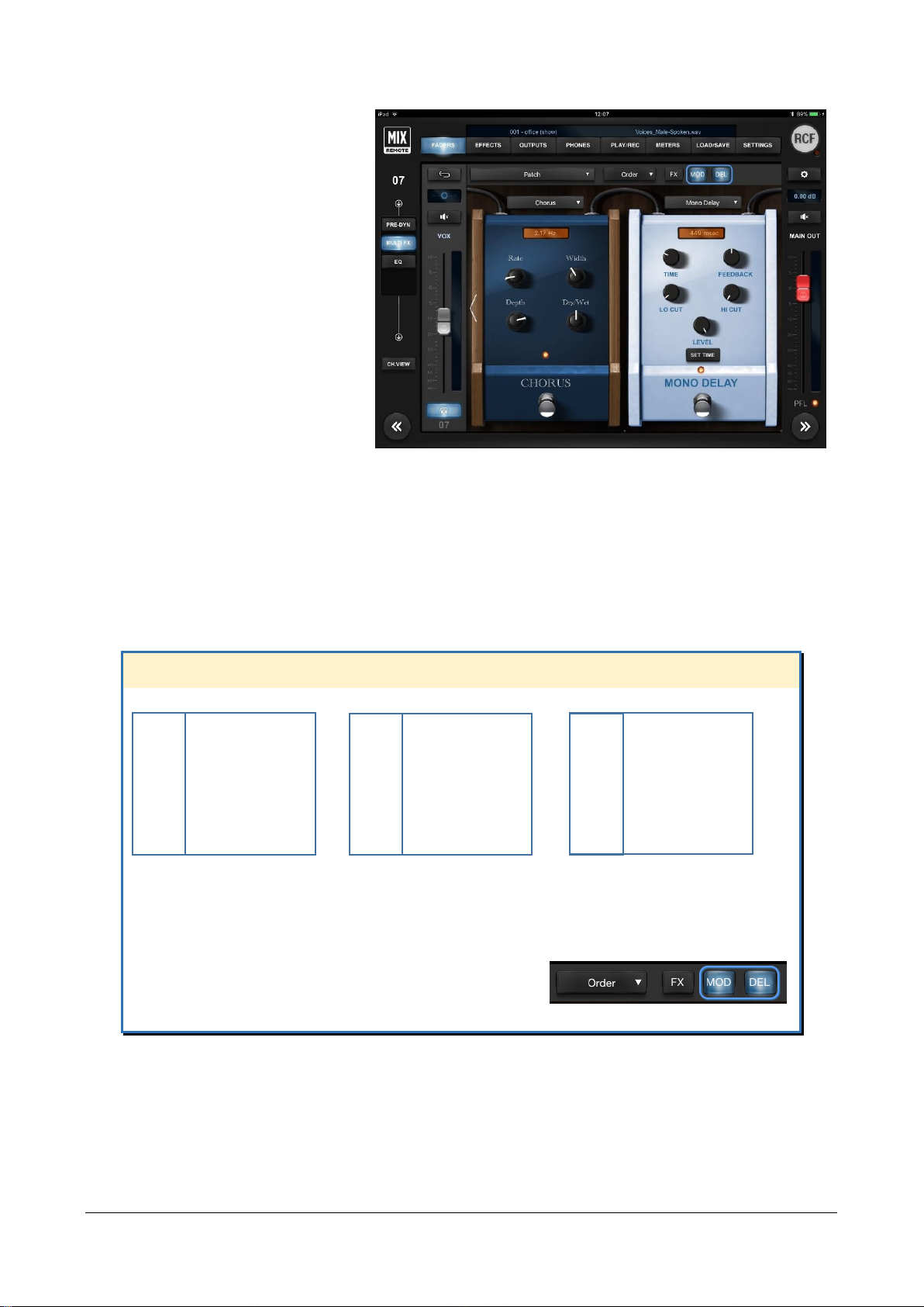
Inputs 5-6 and 7-8 left column is a little
bit different, since these channels may
have MultiFX (MFX) additional
section. MFX assignment is made in
SETTINGS tab GLOBAL page.
The MultiFX section allows you to use
up to three chained effects selectable
between MOD (Chorus, Flanger or
Tremolo), FX (Pitch Shifter, Auto Wah,
Ring Modulator, Octaver), and DEL
(Mono Delay, Vintage Delay, ER Delay).
Pressing the Order selector appears a
drop-down menu allowing you to
choose the order of effects which
better suits your needs for each song,
as you can see in above pictures.
At the top of each pedal there's a display showing the last modified control value. At the bottom there's the
activation switch; its status is displayed by a light which is lit when the unit is on.
IN DEPTH
These channels let you use up to three cascaded effects types:
MOD Chorus FX Pitch Shifter DEL Mono Delay
Flanger Auto Wah Vintage Delay
Tremolo Ring Modulator ER Delay
Octaver
You can change the order of cascaded effects through the selector Order, and view the result on
the top right indicators. These indicators show the ON/OFF status, an also allow you to select
which pair of effect is visible on the central section for editing. The order from left to right of the
FX, MOD and DEL buttons reflect the actual audio cascading.
If you touch any of the effect button, the editing view
for effects will shift to include the effect you have selected.
Page 22
RCF S.p.A. M 18 Digital Mixer User’s Manual 22
Inputs 09-10
Hardware inputs 09 and 10 have line-level sensitivity, but also allows the direct connection of electric guitar
and bass instruments, as they feature a Hi-Z option.
The -10dBV and +4dBu options are similar to the other line-level inputs; the Boost option allows you to insert
another 2 dB boost to the analog stage; while the Hi-Z option enables a real high-impedance stage to get the
best sound from your passive instrument. When in Hi-Z mode, the impedance is 1 MΩ. When using active
instruments, we suggest maintaining the Hi-Z option OFF.
These two channels offer additional capabilities to tailor your own sound, as they both feature a 5-effect
MultiFX.
Similarly to channels 5 to 8, the effects are
displayed in pairs, and you can jump to the desired
insert effect by touching the dedicate button on
top right (see the red box here below).
You change effect daisy-chaining using the Order
Selector, immediately to the left of the insert
sequence indication. If you drag the rightmost part
of the list, you can modify the insert position of a
specific effect, and the change is effective
immediately.
Page 23

RCF S.p.A. M 18 Digital Mixer User’s Manual 23
At the top of each
pedal there is a display
showing the last
edited control value.
At the bottom there is
an activation switch;
its status is displayed
by a light, which is lit
when the unit is on.
The OD section allows
choosing between an
Overdrive and a
Distortion effect,
modeled after wellknown stomp boxes
that have been used
by guitar players for
decades.
The AMP section allows choosing between AMP+CAB models and an Acoustic Simulator. If you choose
AMP+CAB models, tapping anywhere on the pedal, you will be directed to the dedicated AMP page with
several useful controls and with its drop-down men you can quickly select the amplifier type.
IN DEPTH
These channels let you use up to five cascaded effects types:
MOD Chorus FX Pitch Shifter AMP AMP+CAB Models
Flanger Auto Wah Acoustic Simulator
Tremolo Ring Modulator
Octaver
DEL Mono Delay OD Overdrive
Vintage Delay Distortion
ER Delay
You can change the order of cascaded effects through the selector Order, and view the result on
the top right indicators. These indicators show the ON/OFF status, an also allow you to select
which pair of effect is visible on the central section for editing. The order from left to right of the
FX, OD, AMP, MOD and DEL buttons reflect the actual audio cascading.
If you touch any of the effect button, the editing view for effects will shift to include the effect you
have selected.
Page 24

RCF S.p.A. M 18 Digital Mixer User’s Manual 24
Let’s see an example of the following effects order. By tapping on the buttons at the top right, you obtain
different views with 2 effects at time.
FX: Pitch Shifter OD: TubeNine
AMP: Darkface65
MOD: Chorus
DEL: Mono
By tapping the AMP stomp box, a new page
shows up, with all the relevant parameters
on a single view for maximum editing
efficiency.
There are 15 Head Amps and 11 Cabinets
available.
Each Head AMP simulation has a preferred
Cabinet combination, and every time you
select a Head AMP, the matching Cabinet
will show up. Then, you can vary the
Cabinet model and experiment with
unusual combinations.
Each Head AMP has up to 6 parameters
that accurately model the controls
available on the original amplifiers.
The ON/OFF rocker switch represents the BYPASS switch, and has same function as the switch on the stomp box view.
As visible on the left, most Cabinets have similar names to the Head AMPs.
Page 25

RCF S.p.A. M 18 Digital Mixer User’s Manual 25
The AMP section offers also a set of Heads and Cabinets
dedicated to bass guitar, covering a wide range of resulting
timbre.
In addition to the OverloudTM models, two well-known
MarkBassTM models have been included.
You can also selet the microphone type which has been used
when modeling the AMP (see below):
RadioElectro 16 (large-diaphragm cardioid dynamic)
American 57 (small-diaphragm cardioid dynamic)
GermanFet 87 (large-diaphragm cardioid condenser)
The choice for microphone position is
between:
Near, on-axis
Near, off-axis
Far (1 metre from cabinet)
IN DEPTH
List of Amp and Cab models:
AMP Darkface ’65 (US) CAB 2x12 Darkface’65 (US)
JazzC (JP) 2x12 Jazz (JP)
Rock ’64 (UK) 4x10 Clst (UK)
Rock 800 (UK) Crunch 4x12 Green (UK)
Rock 900 (UK) Lead 4x12 Vintage (UK)
Top30 (UK) 2x12 OB Top30 (UK)
Modern (US) 4x12 Modern (US)
BassAmp (US) 6x10 Bass Cab
BassMate (DE) 2x12 Bass Cab
Markbass LittleMark (IT) Markbass 151RJ
Markbass TTE500 (IT) Markbass 104HR
Slo 88 Crunch (US)
Slo 88 Lead (US)
Overange 120 (UK)
Heavy 51 (US)
Page 26

RCF S.p.A. M 18 Digital Mixer User’s Manual 26
Inputs 11-18
Hardware inputs from
11 to 18 have line
connections, with the
option to switch
between -10dBV and
+4 dBu sensitivity.
INV and HPF other
controls are identical to
the other inputs, as you
can see on the right.
Stereo Player (from USB flash drive)
TK USB inputs are managed as a stereo input by default, but you can always unlink them in SETTINGS > GLOBAL
page.
As the audio is directly generated in digital, there is no need for PRE or DYNAMICS.
When you have a stereo track, the
typical use is in stereo (linked)
mode.
If you have a mono backing track
on one channel, and the
metronome click on the other,
then you may work in dual mono
mode, which allows you
independent pan and mixing
controls.
Input PEQ
The 4-band EQ page is identical for all input channels - including TK channels. This page is characterized by
the large Preset box, followed by Standard and Advanced boxes and ON switch.
Great versatility is provided by allowing the selection of three different types of equalizer: Standard (a no-frills,
precise EQ), Vintage (modeled after a UK classic EQ), Smooth (whose modeling was inspired by a modern US
EQ). You have a wide choice that can help in providing the right color to your sound. For each of the three
Page 27

RCF S.p.A. M 18 Digital Mixer User’s Manual 27
equalizer types, two options are available: Advanced (showing all the available parameters) and Easy (in which
some of the more advanced controls are hidden to enable a quicker interaction).
In Standard mode, the display shows the operation of the 4-band equalizer (the overall intervention is
indicated by a white line).
The Advanced option provides
variable frequency shelving
filters for low and high bands
and two fully parametric mids,
while the Easy option provides
high and low shelving with
fixed frequency, and selection
of the frequency for mid-low
and mid-high.
The range of intervention goes
from -12.00dB to +12.00dB;
double clicking on the GAIN
resets the value to 0.00dB for
each band, while to completely
turn off the equalizer, you have
a global ON/OFF button right
above the display.
All three models, with the Advanced option, have the following frequency ranges:
Band
Freq. Range
LO
40-400 Hz
MID1
100 Hz – 10 kHz
MID2
100 Hz – 10 kHz
HI
1 – 16 kHz
Page 28

RCF S.p.A. M 18 Digital Mixer User’s Manual 28
Channel View
For each of the input channels, the CH.VIEW page shows an overview of the main parameters of the channel,
allowing a quick control without having to browse through the app pages.
The central part of this page has 3 faders for FX sends and six faders for AUX send levels. Each of the FX send
faders feature a Mute button. To choose the effects of the three sends, please go to the EFFECTS tab. FX sends
are always post-fader, thus allowing the channel level to affect FX send levels, maintaining the desired balance.
AUX1-AUX4 sends are always pre-fader, thus allowing to set the required level independently from channel
level settings – this solution is ideal for stage monitoring. AUX5 and AUX6 can be set pre or post fader
independently for each input channel.
Above the send strips, there is the input signal chain with the On/Off button for each processing algorithm.
For the inputs with MFX, the signal chain also shows all stomp FXs placed in the right order, the Patch menu
for a quick recall of your preferred patches and a Boost button to increase the volume of +3dB or +6dB
according to MFX Boost settings in the SETTINGS > GLOABAL > INPUT page.
Input channels
without MultiFX
Page 29

RCF S.p.A. M 18 Digital Mixer User’s Manual 29
Input channels
with MFX1 or
MFX2
Input channels
with MFX3 or
MFX4
Page 30

RCF S.p.A. M 18 Digital Mixer User’s Manual 30
EFFECTS
The EFFECTS tab contains two pages: SEND and MULTIFX.
The left column shows the SEND and the MULTIFX select buttons; the right column shows usual the MAIN
OUT controls.
SEND FX
The SEND page shows the three rack mount effects units: FX1 for reverbs, FX2 for delays, and FX3 which can
be assigned to one of four different types of delays and modulations effects. On the upper left side over each
rack device, there are small Preset boxes, to recall several factory presets. On the right left side over each unit,
there is a box to choose the effect variation. Only on the third device, there is an additional central box to
choose the effect type among Delay, Chorus-Flanger, Tremolo and Pitch Shifter.
The large display shows parameter values and on the right, there is the activation button for each effect.
The M18 Digital Reverb is a very intuitive and smooth sounding processor, and represents an essential
ingredient of the final mix. Great care has been taken to provide the highest quality algorithms and presets.
Page 31

RCF S.p.A. M 18 Digital Mixer User’s Manual 31
Based on 12 algorithms, it allows to easily find the perfect reverberation for every kind of application in a few
clicks. The algorithms are been designed and tailored to focus immediately the sound you are looking for and
then fine tune it with the essential parameters available through the five pots.
The algorithms are also available in some cases into two variations (Bright/Warm or Digital/Vintage) to further
help in selecting the proper starting point.
Four different reverb types are available:
TYPE
VARIATIONS
Hall
usually perfect for smooth and deep reverberations
large/medium
warm/bright
Room
the algorithm to start with if you are looking for hi
impact reverberations
large/medium
warm/bright
Plate
classic “all purpose” algorithm with unique character
digital/vintage
Ambience
the first choice if you are looking for something to
expand the stereo field or to somehow enhance the
sounds
model 1, model 2
TIP
The reverberation is one of the most crucial signal processors to achieve a correct mix, so it’s very important
to use it with care. Often the reverberation of the venue affects our overall sound, especially because usually
the sound check is done without audience that is another element that can drastically change the
reverberation time of the venue.
So keep in mid to evaluate the reverberation time of the empty venue, and then consider that it will be shorter
with the audience during the live gig; for these reasons, it could be useful to check the amount of the reverb
also on headphones.
A full set of carefully crafted presets are available, grouped into categories as indicated by their prefix:
[MIS]
Miscellaneous, general-purpose
[VOX]
Voice-oriented
[ACO]
Acoustic
Page 32

RCF S.p.A. M 18 Digital Mixer User’s Manual 32
IN DEPTH
The Digital Reverb lets you choose between four Halls, four Rooms, two Plates and two Ambiences.
You can create your own configurations for Hall and Room by modifying the following parameters:
Predelay (delay before reverb)
ER (amount of primary reflections)
Decay (time decay)
Spaceness (percentage of spatialization)
Damping (percentage of absorption of the higher frequencies)
Plate reverb parameters:
Smoothness
Colour
Ambience reverb parameters:
Richness
The Digital Delay can be chosen among Stereo, Vintage, Modern, Dual and ER.
You can create your own settings for Stereo and ER by changing the following parameters:
Time (length of the delay)
Feedback (% of delay feedback)
Lo Cut (low cut filter frequency)
Hi Cut (high cut filter frequency)
Width (amplitude)
Vintage delay parameters:
Offset (offset time compared with main Time) instead of Feedback
Filter (da 0,00 a 100) is a Band-pass filter
Modern delay parameters:
Offset (offset time related to Main Time) instead of Feedback
LoCut (low cut filter frequency) instead of Hi Cut.
Dual delay parameters:
Factor (1/2, 1/3, 1/4, 1/6, 1/8 and 1/16) instead of Feedback
Feedback 2 (% of delay 2 feedback) instead of Hi Cut
Chorus-Flanger parameters:
Rate (frequency swing)
Width (amplitude)
Depth (depth swing)
Feedback (% effect feedback)
Blend (% mix between dry signal and processed)
Tremolo parameters:
Rate (frequency rate)
Depth (depth swing)
Pitch Shift parameters:
Pitch 1 ( voice 1 note interval; from -12 to +12, in semitones)
Pitch 2 ( voice 2 note interval; from -12 to +12, in semitones)
Cent1 (detune of voice 1, in cents)
Cent2 (detune of voice 1, in cents)
Mix (% mix between voice 1 and voice 2)
Page 33

RCF S.p.A. M 18 Digital Mixer User’s Manual 33
MULTIFX
The M series Digital Mixers offer an unprecedented level of integration by offering multiple internal effects that
can be assigned to some of the inputs channels; these effects are additional and independent from the main
effects, which are connected to the internal effect busses.
The aim of multieffect inclusion is to provide a new approach to effect processing, as effect settings can be
effectively combined with mixing parameters. It is thus possible to create a wide variety of sonic results without
additional equipment.
In the M 18 Digital Mixers the internal effects are combined into a total of 4 multi-effects, which are inserted
into 4 input channels. The insertion point is before the EQ section, as follows:
The M18 Digital Mixer offers a total of four independent MultiFX blocks, allocated as follows:
Multieffect
chain
cascaded
effects
Allocated to
input channel
Some usage
examples
MFX1
3
5 (XLR in) or 7 (COMBO in)
Voice, acoustic guitar, percussions, analog synths
MFX2
3
6 (XLR in) or 8 (COMBO in)
Voice, acoustic guitar, percussions, analog synths
MFX3
5
9 (Line in, Hi-Z option)
Electric guitar, electric bass, analog synths
MFX4
5
10 (Line in, Hi-Z option)
10 (Line in, Hi-Z option)
MFX1 and MFX2 feature a Modulation effect, a Delay and a Special FX unit.
MFX3 and MFX4 are similar to MFX1 and MFX2, but they add OverDrive modeling and a high-quality Amp
Simulation section.
The order of cascaded effects can be modified for each patch; the M series has a total of 5 different effect
families, and one of each family is available within a MultiFX block, as follows:
Effect Family
Abbreviation
MFX1,2
MFX3,4
Description
Modulation
MOD
YES
YES
classical modulators typically used for several
instruments (chorus, flanger, tremolo)
Delay
DLY
YES
YES
Several types of mono delays
Special Effects
FX
YES
YES
General-purpose container, including pitch shifter,
Octaver, Auto Wah and Ring Modulator
OverDrive
OD
-
YES
Modeling of classic overdrive stomp boxes,
licensed from OverloudTM
Amplifier
simulation
AMP
-
YES
Accurate modeling of guitar and basshead amps
and cabinets, licensed from OverloudTM and from
MarkBassTM
You can save the all parameters of a specific MFX chain, including effect ordering, within a PATCH, that can
be recalled independently from other mixer parameters. You can recall PATCHes via MIDI program change
message, and you can also individually turn on and off the effects via NoteOn MIDI messages; each MFX
reacts on different MIDI channels, which can be set within the SETTINGS > MIDI page. The dual footswitch
input can be set to control a specific MFX, to either move to next or previous PATCH, or turn individual
effects on and off.
Therefore, you have a high degree of flexibility for controlling MFX chains during a live gig.
PREAMP
PHASE
HPF
MultiFX
AUDIO
IN
To
MIX
BUSSES
A/D
NOISE
GATE
COMP
4-band
EQ
Page 34

RCF S.p.A. M 18 Digital Mixer User’s Manual 34
The four channels that have multiple effects are
shown on the EFFECTS > MULTIFX page. Here
you can also configure which pair of channels Channels 05-06 or Channels 07-08, which are
active in this example – will have the MFX option
active. With the Settings button it’s possible to
jump directly to the SETTING > GLOBAL > INPUT
page and change the MFX1 and MFX2
assignment. Only channels 09 and 10 provide
you five effects.
The order and ON/OFF status of each insert
effect is shown. Pressing any of these buttons or
the blue button, you access immediately the
corresponding channel.
For details about MFX options, please see
Inputs 05-08 and Inputs 09-10 chapters.
OUTPUT
This tab has one page only, which shows the six silver master faders for the AUX sends, the PHONES master
level, as well as MAIN OUT master level on the rightmost column, as in most views.
AUX PEQ
Each AUX output has a * button to recall the settings pages (1), a box indicating the level of the individual fader
in dB (2) and a Mute button (3); just above the fader there is a text field (4) which by default indicates the send
number, but of course can be renamed; the fader (5) for master output level is above output number, which
corresponds to the physical AUX socket.
1
2 3 4
5
Page 35

RCF S.p.A. M 18 Digital Mixer User’s Manual 35
Pressing *, you recall the
OUTPUTS EQ page,
containing the Advanced
EQ for that AUX send; the
other controls are for level
and mute.
The “Advanced” equalizer
features low (40Hz400Hz) and high (1kHz16kHz) shelving and two
fully parametric bands
(range 100Hz-10kHz for
both).
MAIN OUT Processing
The MAIN OUT channel offers a Master Processor and a 31-Band Graphic Equalizer reachable pressing * on
the MAIN OUT strip.
Page 36

RCF S.p.A. M 18 Digital Mixer User’s Manual 36
MASTER PROCESSOR
The M Series Master Processor is the last stage of processing, before the MAIN Graphic Equalizer, and
represents a precious toolset to give a final touch to overall sound. The Master processor is composed of three
individual processors in series: Valve Warmer, Xciter, Maximizer.
These three processors have been developed
to work together or individually, to achieve a
warmer, analog overall sound, but at the same
time to make your sound loud and proud as
required from the contemporary music
business. You can bypass the set of three
processors with a single button, to ease the
evaluation of its effect on the overall mix.
The factory presets are, as always, a great
starting point to easily learn how the three
processors can work together and then to go
ahead creating your own settings.
VALVE WARMER
Very easy to use one knob processor, it allows to vary from subtle warmness to extreme saturated sound.
This processors works like a real analog piece of gear: it means that the resulting sound is depending on input
level; the more you feed it with a louder signal, the earlier you get a saturated sound, so be careful with your
levels inside the mixer and use it very slightly if you want to use it only for warming your sound.
XCITER
It allows to sculp sound with two adaptive curves on the low end and high end. The frequency of these curves
have been tailored to fit easily and quickly every kind of mix.
You can easily achieve a more pleasant and dynamic sound by fine-tuning the overall frequency balance
(Focus) and make it more or less evident (Process).
MAXIMIZER
This is the last processor in the signal flow chain, that allows you to give a final boost to overall sound. This
processor is very transparent and has been designed to be a “set and forget” stage.
With this in mind, the Maximizer is super easy to set with its two knobs:
Boost
: sets the amount of the incoming signal to the maximizer (it’s a boost only knob so rotate it anticlockwise
for NO boost)
Out Celing
: sets the final level (it’s an attenuator knob, so rotate it full clockwise for NO attenuation)
The Maximizer can be also used “to compact” the overall mix sound, so in this case you can use it boosting
and attenuating at the same time.
Valve
Warmer
Xciter
Maximizer
L-R
mix
To
GEQ
To stereo
RECORD
option
Page 37

RCF S.p.A. M 18 Digital Mixer User’s Manual 37
GRAPHIC EQUALIZER
The Main OUT processing provides a 31-Band GEQ with the center frequency of each band spaced 1/3 of an
octave away from the center frequency of the adjacent bands, so that three bands (three sliders on the front panel)
cover a combined bandwidth of one octave.
On the upper side there
are: Preset dropdown to
save and recall your
custom settings, DRAW
button that allow to
manually design your
equalizer curve, 2x button
to double the size of
bands for a more accurate
editing, FLAT button to set
all bands to 0 dB and ON
button to enable or
disable the GEQ.
PHONES
The way the PHONES output works depends on the SETTINGS tab GLOBAL page selection. You can choose
the operating mode between PFL (Pre-Fade Listen) or Personal Mix. The PHONES mode define how the input
signals are routed on the SOLO bus, as shown in the following scheme:
Page 38

RCF S.p.A. M 18 Digital Mixer User’s Manual 38
In Personal Mix mode, the central column of the
PHONES page includes a box indicating the level
of the individual fader in dB or the pan-pot
position, a small Mute button, a text box which by
default is the number of the send, which can be
renamed, and a blue fader for headphone level
and the non-editable number of the hardware
socket. The level is pre-fader.
In PFL (pre-fade listen) mode, the signal to the
headphones is set by the PFL key of each input,
the USB player and FX RET. In this mode the
values of PAN on the SOLO bus is the same of the
values of PAN on the MAIN LR bus.
PLAY/REC
Three tabs are available on the left column, and you can select either the PLAYER, the stereo RECORDER or the
METRONOME views; both PLAYER and RECORDER access files on a USB Mass Storage device (USB pen drive,
or external HDD) attached to the local USB host port. Within specific conditions, player and recorder can
operate simultaneously even on the same USB device. METRONOME is a powerful and useful tool for live or
recording session, designed to help the musician to keep time or to be used as a creative machine playing its
internal sound generators.
PLAY
This view shows the channels TK1 and TK2 of USB playback. Please note that these channels are stereo linked
by default; if you want independent settings for each channel, you have to un-link them using Input Stereo
Links in SETTINGS tab, GLOBAL page. These channels are processed by a dedicated EQ, of the same type as
other input channels; therefore, three types are available (Standard, Vintage, Smooth) each with two modes
(Advanced and Easy). The M 18 Player also supports 4-tracks playback, with Track 1 and Track 2 on Channels
TK1 e TK2 and Track 3 and Track 4 routed on Channel 17 and Channel 18 according to the input routing settings
on the SETTINGS > GLOBAL > INPUT page.
Page 39

RCF S.p.A. M 18 Digital Mixer User’s Manual 39
On the right side of these controls, there is a time indicator (1); by default, it shows the remaining time to the
end of file. By clicking on the time indication, you can toggle the value shown to represent the time elapsed. A
scroll bar (2) shows the current position within the file; you can grab the scroll bar and move to the desired
position, either when in playback mode or stop mode. A drop-down selector (4) on the upper right corner
allows the selection between different 4 USB flash drives; this is required in case multiple USB flash drives are
connected through a USB hub.
On the upper bar, on the right side, you can view (3) the file currently selected on the player.
A large selection pane allows you to navigate through the USB flash drive folder (upper section), and then to
select the specific files (lower section). To navigate to the previous directory, in the folder section, you can click
on the line with 3 dots.
Please notice that with a very large amount of files, it takes several seconds to show all
file names.
Under this window there are the following player controls:
AUTO ON
AUTO OFF
PREV
Go to previous file in
list and PLAY
Go to previous file in list
and STOP at beginning
NEXT
Go to next file in list
and PLAY
Go to next file in list and
STOP at beginning
STOP
STOP current playback and rewind to beginning of file
PLAY/PAUSE
Toggle between playback of current file and PAUSE at
current position
3
4
2
1
Page 40

RCF S.p.A. M 18 Digital Mixer User’s Manual 40
The following audio file formats are supported by the player and shown in the file list:
• WAV stereo audio files; 44.1 and 48 kHz, 16- and 24-bit (*.WAV extension)
• WAV multichannel audio files; 44.1 and 48 kHz, 16- and 24-bit (*.WAV extension), max 4 tracks
• AIFF stereo audio files, ; 44.1 and 48 kHz, 16- and 24-bit (*.AIF and *.AIFF extensions)
• MP3 stereo audio files (*.MP3 extension)
REC
The REC window allows high-quality, stereo recording of the MAIN left and right channels. The tap point is
after the Mastering processor, and before the Graphic Equalizer (which is generally used for settings that are a
function of the available amplification system).
The currently available format is 24-bit, 48 kHz (the internal sample rate of the M18 Digital Mixer).
As the recording level greatly depends on the number of active inputs, a wide-range Rec Trim control (1) is
available. The minimum value of -18 dB is intended for full use of the mixer, with all inputs being used.
The meter (2) below shows the audio level after the Rec Trim regulation, so that you can check if you are too
close to clipping.
All recordings are stored in the /REC folder within the USB Mass Storage device being selected on the upper
right selector (3).
A default name is generated if no specific name is entered, of the form m18_capture_XXXX_0.wav, where XXXX
is a numeric counter to ensure a unique filename.
To modify the filename, it is sufficient to touch the folder/filename area (6) and a text entry popup shows up.
If a name is given, the numeric counter is automatically appended every time a new record begins.
Valve
Warmer
Xciter
Maximizer
L-R
mix
To stereo RECORD section
Graphic
EQ
Page 41

RCF S.p.A. M 18 Digital Mixer User’s Manual 41
The file is auto-saved every ten seconds, so that any unwanted interruption (i.e., the USB storage device is
removed abruptly, or M18 power is turned off) does not result in a total loss of audio data.
Two time indications are shown: the time since start of recording (5) and the remaining time (4) calculated
on the available storage size. A progress bar (7) shows the status compared to the remaining time, defined
as above.
While M18 is quite flexible in terms of USB storage device capabilities for playing back files, a good quality
device is required for recording on USB in real-time.
FAT32 is the only supported file format on M series digital mixers, and is also the safest cross-platform (Mac /
PC) format. Avoid FAT16 formatting, as random problems in audio file playback have been noticed.
Please notice that the minimum supported USB drive size for audio recording is 4 GB (mainly due to variations
if formatting results for smaller size devices).
Furthermore, consistent and error-free results have been obtained with premium, good-quality USB pens.
Several lower-quality devices can cause random errors due to their lower data transfer performance. USB 3.0
compatible storage devices are recommended, as these guarantee higher data throughput.
Due to filesystem limitations, the internal recorder can generate a file with maximum size of 2 GB,
corresponding to about 2 hours of continuous recording. If this limit is exceeded, the recorder closes the
current file and creates another file with no audio gap, without interrupting the recording process. Thus, the
complete recording can be reconstructed on audio editing software.
We have found that on several USB devices it is recommended to have at least 50% free space on the USB key;
beyond this percentage, most USB keys show significant fragmentation and in this case glitches can appear in
recorded files.
2
1
3
4
5 6 7
Page 42

RCF S.p.A. M 18 Digital Mixer User’s Manual 42
In case you need to reformat a USB pen for audio recording, please follow these guidelines:
Operating System
FORMAT settings
Windows (any)
File System = FAT32, Allocation Unit Size = Default
Mac OS X
Format = MS DOS (FAT32), Scheme = Master Boot Record
METRONOME
The METRO window accesses the internal Metronome that can be routed on channel 18 according to SETTINGS
> GLOBAL > INPUT setup. When the Metronome is routed on channel 18, you can use all the features and
possibilities of an audio channel, such as sending it on the personal mix and with the pan assign the click to
one channel only; i.e., to the right or left side of the headphones for the drummer. Metronome settings are
saved in the Snapshots so it’s possible to recall a click configuration for each song.
M 18 Metronome offers these controls:
BPM (1): set the beat rate typing the desired value, using TAP button or scrolling the bar.
Number of Bars (2): set the duration of the metronome expressed in number of bars, after which it will stop.
If Free option is enabled, the metronome will continue to roll until the STOP button is pressed.
Time Signature (3): it’s possible to set the number of beats in the range [1 : 12] and the time division between
4 and 8. Therefore, all combinations can be accomplished.
Sounds (4): two lists of sounds are available to set independently the 1st beat of the measure and the other
beats.
START (5): Start/Stop button. This control is also available as MIDI Note On.
1 2 3
4
5
Page 43

RCF S.p.A. M 18 Digital Mixer User’s Manual 43
METERS
This tab has just page, which provides an
instant view of the levels of all INPUTS including the PLAYER – and of three FX
stereo returns (RTNS).
The lower section shows the output
levels of the three FX SENDS and the
OUTS level of the six AUX sends.
This view is very useful to quickly check
which signals are actually active, and it is
recommended to check this view every
time you want to verify the mixer status.
LOAD/SAVE
The mixer handles the many hundreds parameters available in a specific way that has been tailored to the
needs of the performing musician. The following parameters groups can be identified:
• Global configuration parameters: they are stored in the mixer as soon as they are modified
• Network configuration parameters: they need a mixer reboot to become effective
• SHOW: it includes all mixer parameters, except configuration parameters
• SNAPSHOT: as a SHOW, but without output related parameters, and may include recall of
PATCHes
• PATCH: it includes multieffect parameters (MFX1, MFX2, MFX3, MFX4)
The SHOW is best suited to save all settings after a sound check, or to store the equalization settings of a
specific venue; it can then be recalled when doing a live act in the same venue.
The SNAPSHOT is ideal for storing all the settings that are related to a specific song or context; i.e., you can
change EQ and equalization types on all input channels, as well as all send effects (both send levels and effect
types).
When using the M 18 as a submixer, you can also save input channels levels by enabling the Mix Bus option
during Save; this helps in obtaining a consistent audio result.
This section features four pages: SNAPSHOT, SHOW, PATCH A and PATCH B. Using these pages you can
save up to 200 SNAPSHOT presets, 100 SHOW presets, 200 PATCH A presets and 200 PATCH B presets that
you can recall later by pressing the Load button after selecting the desired snapshot/show/patch number.
Page 44

RCF S.p.A. M 18 Digital Mixer User’s Manual 44
We can show an overview of M 18 Digital Mixer parameters and the various ways of saving them as follows:
Every group is detailed in the following table:
Group
Parameters
Notes
Global
Configuration
NETWORK/LAN Settings
NETWORK/WLAN AP Settings
+48V Phantom Enable
PHONES Mode (PFL/Personal Mix)
MFX1, MFX2 Routing
Footswitch Settings
Outputs Routing
Snapshot Settings (save of MFX patch numbers)
Startup Setting
MIDI settings
PLAYER AUTO Mode ON/OFF
The NETWORK subgroup require a
reboot to become effective
MFX1
MFX2
MFX3
MFX4
GLOBAL
CONFIGURATION
NETWORK
parameters
Mix bus
Snapshot-related parameters
Show-related parameters
GEQ
SHOW
MFX1
MFX2
MFX3
MFX4
GLOBAL
CONFIGURATION
NETWORK
parameters
Mix bus (not enabled at save)
Snapshot-related parameters
Show-related parameters
GEQ
SNAPSHOT (no Mix bus)
PATCH numbers
(if enabled in SETTINGS > SYSTEM)
MFX1
MFX2
MFX3
MFX4
GLOBAL
CONFIGURATION
NETWORK
parameters
Mix bus (enabled at save)
Snapshot-related parameters
Show-related parameters
GEQ
SNAPSHOT (with Mix bus)
PATCH numbers
(if enabled in SETTINGS > SYSTEM)
Page 45

RCF S.p.A. M 18 Digital Mixer User’s Manual 45
SHOW
related
INPUTS CH. PRE (GAIN, TRIM, PHASE, HPF, HiZ)
INPUTS CH. STEREO LINK settings
OUTPUTS LEVEL (Main Out, AUX Out, Phones
Out)
INPUTS CH. names
OUTPUT CH. names
AUXs BUS (Level, Mute)
PHONES BUS (Level, Mute, Pan/Balance)
AUX OUT EQ parameters
PHONES EQ parameters
All MFX1, MFX2, MFX3, MFX4 parameters
AUX 5-6 CH. PRE/POST settings
GEQ ON/OFF
A SHOW saves the complete mixer
state (inputs, outputs, processing)
GEQ
Stereo 31-band Graphic EQ settings
May be saved and recalled
independently
SNAPSHOT
related
INPUTS CH. EQ parameters
INPUTS CH. GATE parameters
INPUTS CH. COMPRESSOR parameters
INPUTS CH. names
OUTPUT CH. names
SEND EFFECTS parameters
MASTER PROCESSOR parameters
FXs Bus (Level, Mute)
Mix Bus parameters (if enabled at save)
MFX1 PATCH number (if enabled in SETTINGS)
MFX2 PATCH number (if enabled in SETTINGS)
MFX3 PATCH number (if enabled in SETTINGS)
MFX4 PATCH number (if enabled in SETTINGS)
A SNAPSHOT saves all the parameters
not directly related to the outputs
Mix Bus
INPUTS BUS (Level, Mute, Pan/Balance)
May be included in a SNAPSHOT
Input PEQ
Input Channel Parametric EQ settings
May be saved and recalled
independently
MFX1
DLY parameters
FX parameters
MOD parameters
FX order
MFX1 is a daisy-chain of 5 individual
effects (DLY, FX, MOD, with assignable
order); affects input channel 5 or 7
MFX2
DLY parameters
FX parameters
MOD parameters
FX order
MFX2 is a daisy-chain of 3 individual
effects (DLY, FX, MOD, with assignable
order); affects input channel 6 or 8
MFX3
DLY parameters
FX parameters
MOD parameters
OD parameters
AMP parameters
FX order
MFX3 is a daisy-chain of 5 individual
effects (DLY, FX, MOD, OD, AMP with
assignable order); it affects input
channel 9
MFX4
DLY parameters
FX parameters
MOD parameters
OD parameters
AMP parameters
FX order
MFX4 is a daisy-chain of 5 individual
effects (DLY, FX, MOD, OD, AMP with
assignable order); it affects input
channel 10
Page 46

RCF S.p.A. M 18 Digital Mixer User’s Manual 46
Each page provides a set of functions to easily manage presets, as follows.
EXPORT
You can save a preset block from the
mixer to a file on USB mass storage
devices, specifying file name and
number of presets to consider, starting
from the specified location. A folder for
each preset type will be created on the
USB drive:
/mxx/snapshot
/mxx/show
/mxx/patch_a
/mxx/patch_b
IMPORT
You can load a block (or a sub-portion)
of presets from a previously saved file on
USB mass storage device to the mixer,
specifying number of presets to
consider and location to start from.
COPY
You can copy a preset block into another
range. This function is useful to duplicate
or to delete some of your stored preset.
Page 47

RCF S.p.A. M 18 Digital Mixer User’s Manual 47
SWAP
You can swap two presets blocks.
This function is useful to arrange n
different way your stored items.
SNAPSHOTS
A Snapshot Load action does not mute the audio outputs, but applies parameter changes smoothly to minimize
audio artifacts.
Please note that in SETTINGS >
SYSTEM page you can select
whether to include MFX patches
recalls independently for each MFX.
When saving a Snapshot, you have a
further option: you can enable the
save of Mix Bus parameters. This is
useful when the M18 Digital Mixer is
being used as a submixer, in which
case the channel levels are part of
the overall sound creation process.
To load a Snapshot, first select the
Snapshot number on the left pane,
and the press Load.
It’s also possible to load a specific snapshot using a MIDI program change, or increment/decrement snapshot
number to load using MIDI Note On messages. Refer to the MIDI Chart to for MIDI commands details.
Page 48

RCF S.p.A. M 18 Digital Mixer User’s Manual 48
SHOWS
The Show includes all parameters
pertaining to inputs and outputs,
except the global configuration
parameters. A Show Load action mutes
all outputs, to avoid sudden level
changes.
To load a Show, first select the Show
number on the left pane, and the press
Load.
To save a Show, first select the Show
number on the left pane, and the press
Save; you have the option to edit the
Show name before confirming the Save
operation.
PATCHES
Patches include all parameters related to each multieffect, and are thus available for MFX1, MFX2, MFX3 and
MFX4. M 18 provides two distinct multieffect types:
• three effects in series: this applies to MFX1 and MFX2, which are available on channels 5-6 or
channels 7-8, according to settings
• five effects in series: this applies to MFX3 and MFX4, which are available on channels 9-10.
MFX1 and MFX2 presets are saved as PATCH A types, MFX3 & MFX4 presets are saved as PATCH B types.
In addition to internal effects, PATCH A and PATCH B also save the BOOST parameter placed at the multieffect
chain end. Saved Patches are recallable from the menu available on FADERS > INPUTS > MFX or on FADERS >
INPUTS > CH.VIEW.
Page 49

RCF S.p.A. M 18 Digital Mixer User’s Manual 49
For each MFX, you can load a specific
patch using MIDI program change
messages, or increment/decrement
patch number using MIDI Note On
messages. Refer to the MIDI Chart to
for MIDI commands details.
SETTINGS
The SETTINGS view allows access to all global configuration parameters. Four tabs are available, on the left
column.
GLOBAL
This page contains six tabs that offer settings affecting the operating mode of the mixer.
INPUT
Page 50

RCF S.p.A. M 18 Digital Mixer User’s Manual 50
The 48V Phantom Enable section allows the activation of 48V phantom power for microphone inputs in
groups of four, using Channel 1-4 and Channel 5-8 buttons.
The Input Routing section selects the audio source for Channel 10, Channel 17 and Channel 18:
Ch10: Analog Input 10 or Analog Input 9; when selecting Analog Input ➔ channel 10, the same audio
source will be sent to both audio channels, each one with full processing and its MFX. This
configuration is dedicated to musicians that wants to experiment with parallel FX processing.
Ch17: Analog Input 17 or Player Track 3; the latter is available when a Multichannel WAV file is
selected from the player.
Ch18: Analog Input 18, Player Track 4 or Metronome. Player track 4 is available when a Multichannel
WAV file is selected from the player.
The Input Stereo Links section allows you to link in stereo an odd channel with the next even channel. After
the link, all settings from the odd channel will be copied to the even channel, and in the bottom row the
numbers of paired inputs will show up (e. g. 03-04) below a single fader with stereo VU meter. The Link option
is available for all inputs (1 to 18) plus the stereo player from USB flash drive. By default the player is linked in
stereo.
The MultiFX Settings section allows inserting the MFX1 and MFX2 into channels 5 and 6 or into channels 7
and 8.
The Snapshots includes section allows to enable MFX patch number recall when a Snapshot is loaded,
independently for each MFX. In this way, you can connect your saved Patches to the current Snapshot.
The FX Boost section allows setting at either +3 dB or +6 dB the boost level placed after each MFX.
OUTPUT
Page 51

RCF S.p.A. M 18 Digital Mixer User’s Manual 51
The Phones Mode section allows selecting between PFL (on FADERS INPUT page) and Personal Mix for the
headphone output.
The Output Routing section has drop-down menus to choose the source for several physical output:
• AUX1 output: AUX1 bus, MAIN L (after Master Processor), PHONES L bus or MAIN L+R
• AUX2 output: AUX2 bus, MAIN R (after Master Processor), PHONES R bus or MAIN L+R
• AUX3 output: AUX3 bus, MAIN L (after Master Processor), PHONES L bus or MAIN L+R
• AUX4 output: AUX4 bus, MAIN R (after Master Processor), PHONES R bus or MAIN L+R
• AUX5 output: AUX5 bus, MAIN L (after Master Processor) or PHONES L bus
• AUX6 output: AUX6 bus, MAIN R (after Master Processor) or PHONES R bus
• PHONES output: MAIN or PHONES busses
DCA GROUP
This page handles DCA groups assignments to each input channel. M 18 offers four DCA Groups (with Mute)
controllable with the faders strips available on the page FADERS > INPUTS, at the rightmost end.
Page 52

RCF S.p.A. M 18 Digital Mixer User’s Manual 52
When a DCA Group is assigned to an input channel, the DCA group number is shown on top of the channel
strip meter, so that you can easily visualize the assignment.
MIDI
This page manages MIDI settings; you can also disable reception of MIDI commands.
Page 53

RCF S.p.A. M 18 Digital Mixer User’s Manual 53
Section
Default
MIDI ch
Description
Global
10
Allowed messages include output levels (Control Change), player
control (Note on) and snapshot load (Pgm Change)
MFX1
11
Multieffect MFX1 (assigned to either input ch 5 or 7) patch change (Pgm
change) and individual effect toggle (NOTE on)
MFX2
12
Multieffect MFX1 (assigned to either input ch 5 or 7) patch change (Pgm
change) and individual effect toggle (NOTE on)
MFX3
13
Multieffect MFX3 (assigned to input ch 9) patch change (Pgm change)
and individual effect toggle (NOTE on)
MFX4
14
Multieffect MFX4 (assigned to input ch 10) patch change (Pgm change)
and individual effect toggle (NOTE on)
Page 54

RCF S.p.A. M 18 Digital Mixer User’s Manual 54
FOOTSW
The Footswitch section allows you to
define footswitch operation.
Mode allows you to choose between
LATCHING or MOMENTARY N.C.
(Normally Closed) footswitch contact,
for both switches.
Then, SW1 assign (TIP) and SW2 assign
(RING) drop-down menus list all the
options that can be assigned to each of
the two switches (see below)
CH. SAFE
This page allows to remove from
snapshots and show recall the active
selections, leaving the corrisponding
input, output, FX or DCA Groups
unchanged.
MFX1 DLY On/Off
MFX1 Patch Prev
MFX1 MOD On/Off
MFX2 Patch Prev
MFX1 FX On/Off
MFX3 Patch Prev
MFX2 DLY On/Off
MFX4 Patch Prev
MFX2 MOD On/Off
Player Play
MFX2 FX On/Off
Player Next
MFX3 DLY On/Off
Player Prev
MFX3 MOD On/Off
Snapshot Next
MFX3 FX On/Off
Snapshot Prev
MFX3 OD On/Off
MFX1 Boost
MFX3 AMP On/Off
MFX2 Boost
MFX4 DLY On/Off
MFX3 Boost
MFX4 MOD On/Off
MFX4 Boost
MFX4 FX On/Off
Mute OUTS
MFX4 OD On/Off
Mute FX
MFX4 AMP On/Off
Mute Group 1
MFX1 Patch Next
Mute Group 2
MFX2 Patch Next
Mute Group 3
MFX3 Patch Next
Mute Group 4
MFX4 Patch Next
Page 55

RCF S.p.A. M 18 Digital Mixer User’s Manual 55
SYSTEM
This page contains system settings affecting the M 18 Digital Mixer operations.
The ONLINE and OFFLINE buttons allow a change of connection status. Immediately below, there's a text
line indicating the mixer status (
Mixer disconnected
or
Mixer connected
).
The cursor below (Go OFFLINE if the mixer is disconnected for) allow the connection timeout selection, in a
range from 1 minute to 30 minutes. We suggest to keep it to the maximum value.
WARNING: if disconnection is frequent, please check the WLAN connection in SETTINGS > NETWORK.
The Startup Mode can be one of the following two options;
- Init Mixer: the mixer powers up in initialized state, with all faders turned down
- Last show: at power-up, the mixer loads the last show that was either loaded or saved
The Restore Default option allows to load the default values of all parameters maintaining your saved shows,
snapshots, patches and global configurations.
In case of communication issues between the tablet and the mixer itself, you can press Resync Data, which
recalls the last active status of the mixer, including all the changes done.
Enabling the Advanced Settings option you will have access to:
• WLAN/LAN Bridge enables a bridge between the Internal WiFi AP and an external network connected
to the M18 via a LAN cable. In this way, you can connect your devices to the M18 internal WiFi AP
allowing both MixRemote control and web navigation (if the network has an internet connection). This
option is not indicated when the M18 WiFi network is weak. To make this option effective, a reboot is
required.
• Documentation Mode contains information for our team... nothing useful for normal use ☺
• Random VU Meters activates VU Meters when the mixer is disconnected, and is used for demo
purposes only!
Page 56

RCF S.p.A. M 18 Digital Mixer User’s Manual 56
NETWORK
Two sections are accessible
from the NETWORK view: on
the left side, for the wired LAN
port; on the right side, for the
internal Wireless LAN Access
Point.
LAN Settings: all network-related adjustments can be made, such as IP Address, Netmask, Gateway and
DNS. These settings are usually left to factory values, but they can be modified for special uses. Standard usage
of the M18 Digital Mixer does not require the LAN port.
WLAN Settings: all WiFi-related adjustments can be made, mostly like a standard WiFi Access Point. The
parameters are described in detail here:
SSID
You can modify the factory setting to provide a name you can remember. The factory name is
in the form M18-XXXXXX where the latter are a combination of letters and numbers.
Country
By selecting the appropriate country where you are operating the mixer, you can comply with
local radio regulations. Please notice that if you leave to the default value NONE, transmitting
power is limited and you will not obtain the best performance from the M 18 Digital Mixer,
including maximum distance and robustness to interference
(feature not allowed on USA/Canada software version)
Band
You can select between the usual 2.4 GHz band and the less crowded 5 GHz band, depending
on your tablet capabilities. For USA and Canada markets, the 5 GHz band is not allowed,
according to the local FCC/IC regulations.
Channel
You can minimize interference from other Access Points by selecting a channel not being used
by others. There are several scanning software applications that enable you to view which
channels are available.
Security
You can either keep the Access Point open, or enable WiFi security (WPA2/PSK). In this case,
you will be able to modify the default password.
And as a last option, you can choose between internal or external Antenna.
After you perform all changes to either LAN or WLAN parameters, you must press SAVE to modify these
settings into the mixer. For LAN Settings only, a reboot is required after changes to make them effective.
Page 57

RCF S.p.A. M 18 Digital Mixer User’s Manual 57
INFO
In this view, it’s possible to check some system information:
• Application Version: this is the current version of the MixRemote app. This number is different for iOS
and Android application
• Firmware Version: this is the current version of the firmware that runs inside the connected M18
digital mixer.
• Mixer Serial Number: this is a unique ID that allows the manufacturer to identify each unit.
We recommend always updating both firmware and applications (iOS & Android) with latest versions.
Page 58

RCF S.p.A. M 18 Digital Mixer User’s Manual 58
6. M 18 Usage
Secret of mixing on a digital console
The most important thing to keep in mind using a digital console is the Gain Structure.
Mixing is essentially an art, but the Gain Structure is based on mathematical reasoning and represents the most
important thing to learn to manage before taking off with your mixing creativity!
The correct input level, starting from the Analog Gain, with all the further processing inside the mixer, must be
set by checking continuously the master output to avoid overload because digital consoles work differently
from analog ones.
The 0dBFS level (where FS stands for full-scale) refers to sound level in the digital domain, inside the mixer
itself, and corresponds to the maximum signal that can be applied to an Analog-to-Digital conversion stage:
above this level, the conversion process clips the signal and sever distortion appears.
A fair starting point to set the proper Analog Input Gain is to set the individual sounds levels in the range of 18 .. -14 dBFS.
One of the most powerful but often underestimated tools is the High-Pass Filter (HPF); in the M Series mixer
the HPF is located in the PRE-DYN page. The proper HPF setting on the individual channels is important to
optimize the processing of the audio sources, and furthermore it also helps to cut away some subsonic
inaudible components of the sounds that often cause an efficiency loss of the power amplification system.
It’s highly suggested to always use the HPF on all the input channels, especially on mic inputs during live gigs
where the HPF is a great tool to reduce the noises captured by the microphones by transmission (as an example,
foot stomping or noises captured touching the mic stands).
How to set the HPF?
Generally, except for instruments with lot of low end like a Kick Drum or Bass, 50Hz is a good frequency to
start with. The HPF is not only the first tool to optimize the signal chain but it must be considered like an EQ
band, and for this reason it should be used to easily optimize the frequency range aimed to achieve a more
focused overall balance between the different sounds
A classic example of HPF usage in frequency range optimization is on the Toms. When played alone, Toms
have huge energy in the low end; in a mix of medium density of instruments the perception of those low
frequencies is masked by other instruments, so to make the Tom sound more focused we could boost some
mid-hi frequency or cut some low end with the HPF – 100Hz and above - and increase the level.
This approach allows to keep the same RMS audio level (matching the perceived audio level), but with an
optimized frequency range.
The approach described for Toms above should be reiterated for all instruments.
Gain Input Level, HPF and Gain Structure are the most important elements to keep in mind for the usage of a
digital console.
Page 59

RCF S.p.A. M 18 Digital Mixer User’s Manual 59
Sound Shaping with M 18
A full array of processors is available on each M Series Mixer’s channel: HPF, Gate, Compressor, Insert, Equalizer, Three Fx
Sends. They allow to tailor every kind of sound not only for correction but also with a creative approach.
The Gate with its full set of controls allows to be optimized for every kind of incoming signal, even the most complex and
difficult to tame. The Compressor can be at the same time super transparent but also very aggressive. The Equalizer is the
essential mixing tool, and is available in three variations: Standard, Vintage, Smooth. The Vintage and Smooth types have
been derived from models of classic analog equalizer banks that have been used in countless recordings and mixing
sessions. For each type, an
EASY
mode is available, showing the essential parameters only, and is perfect for superfast
usage.
Which are the features of each type?
Standard
This is the most transparent type of Equalizer in the M series Digital Mixer.
Four bands ideal for every kind of correction but also perfect to tailor the sounds without colorations.
Vintage
This Equalizer is modeled after the Classic British EQs.
It’s the first choice when you are looking for an Equalizer with character and impact.
Smooth
This is a really unique Equalizer.
The two Mid bands have been designed to shape gently the frequencies and the two Shelving sections
have been developed to cut gently some frequencies in conjunction to their boost.
These features allow to shape sounds carefully, placing them into the mix with unparalleled smoothness.
The large number of presets are ideal to learn more about the power of Equalizer types and they represent an invaluable
starting point to create your own unique sound. To simplify navigation, equalizer presets have been grouped in classes
depending on the instrument being targeted; groups are identified by the prefix assigned to each preset, as follows:
[DRM]
Drums
[KEY]
Keyboards
[PRC]
Percussion
[VOX]
Voice
[BSS]
Bass [ORC]
Orchestral
[EGT]
Electric Guitar
[MIS]
Miscellaneous
[AGT]
Acoustic Guitar
Let’s take a look to some real examples and usage tips.
DRUMS
Gate and Compressor are processors heavily used on drums and percussions.
Among the various Equalizer options, the Vintage Type is for sure the most recommended if we are looking for a sound
shape with character. The Standard Equalizer Type is still the first choice for surgical corrections and for transparent
shaping. The Smooth Equalizer Type is for sure the best choice for soft sounds.
Here are some examples and tips for each part of the drum kit.
KICK
EQ
COMP
GATE
HPF: OFF > 50Hz
Body: 50Hz>150Hz
Resonance (Cut) : 180>400Hz
Attack: 4>8 KHz
Attack: Med-Slow
Release: Med-Fast
Ratio: 4:1>8:1
Attack: 1msec
Hold: 80msec
Release: 50msec
Range: 15 > 50 dB
Page 60

RCF S.p.A. M 18 Digital Mixer User’s Manual 60
TIPS:
the Kick is an instrument that, due to its low end, takes a big part of the RMS level, so it’s very important to define
the frequency range where it will stay in relation to the bass guitar. Generally a good starting point for optimizing the low
end range is to avoid boosting the same frequencies on both the instruments, trying to create some relations between kick
and bass, where the kick wraps the bass and the opposite avoiding – when possible – to overlap frequency ranges.
SNARE
EQ
COMP
HPF: 50 > 250 Hz
Body: 150Hz>250Hz
Resonance (Cut) : 200>400Hz
Attack: 5>8 KHz
Air: 10>12 KHz
Attack: Med-Slow
Release: Med-Fast
Ratio: 4:1>8:1
TIPS:
usually the Snare Drum is miked with two microphones (top and bottom). Sometimes it’s necessary to invert the
phase on one of them, especially is the microphone are positioned almost at 180°. How can you quickly determine if phase
shift is necessary? Take a listen to the two channels in solo and shift the phase of one (generally the bottom); if you hear
the low end increasing, then it would be better to keep the phase inverted, because some phase cancellation is occurring
in absence of phase shift.
TOM
EQ
COMP
HPF: 50 > 200 Hz
Body: 150Hz>250Hz
Resonance (Cut) : 250>600Hz
Attack: 4>8 KHz
Attack: Med-Slow
Release: Med-Fast
Ratio: 4:1>8:1
TIPS:
usually, Tom microphones capture cymbals so it’s advisable to avoid extreme boost in the high-end frequency range;
the Smooth Eq Shelving is perfect to cut some hi frequencies and gentle boost some mid-hi frequencies easily with a single
pot! The first Tom (typically positioned above the snare) usually captures a big part of the snare too. It is better to place
the microphone “looking” in direction of the floor tom but not the snare; this is a simple way to dramatically improve the
efficiency of the Gate too.
HI HAT
EQ
COMP
HPF: 50 > 200 Hz
Body: 150Hz>250Hz
Resonance (Cut) : 250>600Hz
Attack: 4>8 KHz
No Comp
OVERHEAD
EQ
COMP
HPF: 100 Hz > 1 KHz
Body: 150Hz>250Hz
Resonance (Cut) : 800Hz >2 KHz
Air: 10>12 KHz
Attack: Med-Slow
Release: Med-Fast
Ratio: 4:1>8:1
TIPS:
the Overhead can be used in different ways. The classic approach is to capture only the cymbals; in this case, it makes
sense to apply an HPF (above 300Hz) to reduce the presence of other instruments.
Especially in live gigs, it makes sense to use the Overhead also like a “stereo” drum source, using a reduced amount of HPF
and adding a bit of compression and reverb. In this way, the Overhead mics are like the “Room Mics” generally used in
studio recordings that can give to the overall sound a natural spaciousness that it’s hard to achieve with close mics only.
Page 61

RCF S.p.A. M 18 Digital Mixer User’s Manual 61
BASS
Typical processing of the bass input signal requires both Compressor and Equalizer. Due the versatility of the M Series
Compressor, it can be used on bass for several purposes, from increasing the average volume – and limiting some pick –
to adding some attack and aggressiveness to the overall sound. All the EQ types are also usable on bass, with excellent
results depending on the sound we are looking for.
As for the Drums, we recommend to use the Vintage EQ if you are looking for a solid and precise sound. The Standard EQ
is as always a good choice for a neutral and surgical approach to the sound. The Smooth EQ, thanks to its unique curves,
is perfect if you are aiming at a super thick sound avoiding tedious resonance in the mid-low range.
EQ
COMP
HPF: OFF > 40Hz
Presence: 60Hz>100Hz
Body: 100Hz > 150Hz
Resonance: 180Hz >250Hz
Presence: 1KHz>3KHz
Attack: Med-Slow
Release: Med
Ratio: 4:1>8:1
TIPS:
the Bass’s extra Low frequencies could be critical in the overall sound of the mix. It is strongly suggested to check the
extra low frequencies of the kick drum as well, to avoid overlap of the boost of some extra low frequencies. Again, the HPF
is a great and simple tool to focus the low range. Example: if you bass sound has a big presence below the 50Hz maybe it
could be a good idea to check how it sounds in the mix cutting the frequencies below 50 Hz on the kick drum.
KEYBOARDS
The Equalizer is generally the most used processor on keyboards. Compressor is sometimes used to increase the attack (on
the piano for example) and rarely to limit the dynamic range. All the M Series equalizers can be used with great results;
each one, with its own character, is able to tailor the sound in a very pleasant way. The Smooth EQ can be a great choice
to gentle sculpt the sounds increasing the focus and cutting easily at the same time some unwanted frequencies which
usually cause some congestions in the mid-low and mid-hi range. As always, also on keyboards the HPF is the perfect tool
to cut some not unuseful frequencies and immediately clean the mix allowing also to place the keyboard at an highter level
in the mix.
Here are some suggested frequency ranges to be considered when approaching keyboard equalization:
EQ
HPF: OFF > 400Hz
Body: 100Hz > 200Hz
Resonance: 180Hz >500Hz
Presence: 1KHz>3KHz
Attack: 2KHz>8KHz
Definition: 5KHz>12KHz
ELECTRIC GUITARS
The approach to the Electric guitar processing changes a lot according to the original sound. The internal M Series guitar
processor allows tons of tone possibilities that can be fine-tuned also through EQ and Compressor. Of course, you can use
the mixer miking a real amp and cabinet, and in this case the internal processors could be used more to fine tune the
sound.
EQ
COMP
HPF: OFF > 100Hz
Body: 100Hz>200Hz
Resonance (Cut) : 150>400Hz
Presence : 900Hz > 2 KHz
Attack: 2>5 KHz
Attack: Med-Slow
Release: Med
Ratio: 4:1>8:1
Page 62

RCF S.p.A. M 18 Digital Mixer User’s Manual 62
ACOUSTIC GUITARS
Acoustic Guitars are usually amplified during live gigs through a pickup, and only occasionally with mics.
The pickup sounds is often a bit harsh, and it may be necessary to smooth it reducing some extra high frequencies and
adding some warm with EQ and Compressor.
EQ
COMP
HPF: OFF > 120Hz
Body: 100Hz>200Hz
Resonance (Cut) : 150>400Hz
Presence : 900Hz > 2 KHz
Attack: 2>4 KHz
Harshness (Cut) : 8>12 KHz
Attack: Med-Slow
Release: Med-Fast
Ratio: 2:1>6:1
TIPS:
the Smooth EQ is the perfect EQ type to remove some harshness in the high-end, adding at the same time some
definition to the sound of acoustic guitars in the mid-hi range. The Smooth EQ is also great to increase the body of the
sound removing some resonances using only one band!
VOICE
The Voice is a complex “instrument”, mainly because it can be emitted in several different ways. The main problems to
handle, especially during live gigs, are first the control of the dynamic range and then the balance of the frequencies
according to the dynamic. The M Series Compressor is absolutely transparent, and on voices it can be used to control the
dynamic range also hardly without the classic
pumping
side effect.
All the M Series Equalizers can be used successfully to easily tailor the voice tone each one with its own unique character.
If you want to gently boost the voice sound, making it more exciting, the Smooth EQ is for sure the first choice; if you want
an aggressive, in-your-face sound, the Vintage EQ is the recommended selection and, as always, the Standard EQ is the
perfect all-purpose choice.
EQ
COMP
HPF: OFF > 120Hz
Body: 100Hz>200Hz
Resonance (Cut) : 150Hz>300Hz
Presence : 2KHz > 4KHz
Air : 10KHz>16KHz
Attack: Fast-Med
Release: Med
Ratio: 4:1>6:1
TIPS:
when mixing, voice intelligibility is the main concern. The mid range is where the voice is mostly located, so be careful
to check how other instruments work in that frequency range; usually it is better to cut some instruments that over-eq or
increase the voice level.
Page 63

RCF S.p.A. M 18 Digital Mixer User’s Manual 63
7. DECLARATION
FCC / IC CERTIFICATION
M18 digital mixer is approved for FCC rules. The below FCC code allows to find related information:
FCC ID: 2AHDK-M18DIGI
IC: 21113-M18DIGI
This device complies with part 15 of the FCC rules. Operation is subject to the following two conditions:
1) this device may not cause harmful interference, and
2) this device must accept any interference received, including interference that may cause undesired
operation
INFORMATION FOR USERS
NOTE: The manufacturer is not responsible for any radio or TV interference caused by unauthorized
modifications to this equipment. Such modifications could void the user's authority to operate the
equipment.
NOTE: This equipment has been tested and found to comply with the limits for a Class B digital device,
pursuant to Part 15 of the FCC Rules. These limits are designed to provide reasonable protection against
harmful interference in a residential installation. This equipment generates, uses and can radiate radio
frequency energy and, if not installed and used in accordance with the instructions may cause harmful
interference to radio communications. However, there is no guarantee that interference will not occur in a
particular installation. If this equipment does cause harmful interference to radio or television reception,
which can be determined by turning the equipment off and on, the user is encourage to try to correct the
interference by one or more of the following measures:
• Reorient or relocate the receiving antenna
• Increase the separation between the equipment and receiver
• Connect the equipment into an outlet on a circuit different from that to which the receiver is
connected
• Consult the dealer or an experienced radio/TV technician for help
Page 64

RCF S.p.A. M 18 Digital Mixer User’s Manual 64
RADIO CHANNEL SELECTION
Two different options are available, depending on the hardware unit version: for USA/Canada (limited to
channels 1-11), or EU/other countries (channels 1-13 are allowed); refer to Table 1 for more details. The unit
version is clearly indicated in the label placed on the bottom of the unit:
If this label is not present, the unit is configured to access all 13
channels as shown in Table 1, and therefore, according to FCC/IC rules,
it cannot be operated in USA or Canada.
Table 1 – Allowed Frequencies on M 18
WARNING
To avoid interference to local communications, it is strongly recommended to verify allowed frequencies in
the country of use before deploying the product.
ISED compliance statements
This device complies with Industry Canada licence-exempt RSS standard(s) RSS-247 and RSS-102. Operation is
subject to the following two conditions: (1) this device may not cause interference, and (2) this device must
accept any interference, including interference that may cause undesired operation of the device.
Le présent appareil est conforme aux CNR d'Industrie Canada applicables aux appareils radio exempts de
licence. L'exploitation est autorisée aux deux conditions suivantes : (1) l'appareil ne doit pas produire de
brouillage, et (2) l'utilisateur de l'appareil doit accepter tout brouillage radioélectrique subi, même si le
brouillage est susceptible d'en compromettre le fonctionnement.
(compliance statement and unlicensed device usage conditions)
=================================
CAN ICES-3(B)/NMB-3(B)
Page 65

RCF S.p.A. M 18 Digital Mixer User’s Manual 65
Statement for detachable antenna
Under Industry Canada regulations, this radio transmitter may only operate using an antenna of a type and
maximum (or lesser) gain approved for the transmitter by Industry Canada.
To reduce potential radio interference to other users, the antenna type and its gain should be so chosen that
the equivalent isotropically radiated power (e.i.r.p.) is not more than that necessary for successful
communication.
This radio transmitter (identify the devi ce by certification number, or model number if Category II) has been
approved by Industry Canada to operate with the antenna types listed below with the maximum permissible
gain and required antenna impedance for each antenna type indicated. Antenna types not included in this list,
having a gain greater than the maximum gain indicated for that type, are strictly prohibited for use with this
device.
Conformément à la réglementation d'Industrie Canada, le présent émetteur radio peut fonctionner avec une
antenne d'un type et d'un gain maximal (ou inférieur) approuvé pour l'émetteur par Industrie Canada.
Dans le but de réduire les risques de brouillage radioélectrique à l'intention des autres utilisateurs, il faut choisir
le type d'antenne et son gain de sorte que la puissance isotrope rayonnée équivalente (p.i.r.e.) ne dépasse pas
l'intensité nécessaire à l'établissement d'une communication satisfaisante.
Le présent émetteur radio (identify the device by certification number, or model number if Category II) a été
approuvé par Industrie Canada pour fonctionner avec les types d'antenne énumérés ci-dessous et ayant un
gain admissible maximal et l'impédance requise pour chaque type d'antenne. Les types d'antenne non inclus
dans cette liste, ou dont le gain est supérieur au gain maximal indiqué, sont strictement interdits pour
l'exploitation de l'émetteur.
RF exposure limit statement
This equipment complies with radio frequency exposure limits set forth by Industry Canada for an uncontrolled
environment. This equipment should be installed and operated with minimum distance 20 cm between the
device and the user or bystanders.
Cet équipement est conforme aux limites d'exposition aux radiofréquences définies par Industrie Canada pour
un environnement non contrôlé. Cet équipement doit être installé et utilisé avec un minimum de 20 cm de
distance entre le dispositif et l'utilisateur ou des tiers.
Page 66

RCF S.p.A. M 18 Digital Mixer User’s Manual 66
8. Startup Sequence & Recovery
The M 18 Digital Mixer features an advanced booting system that ensures the unit correctly powers up in any
condition. The white front LED gives indications about the startup process, which is divided into several
stages.
STAGE
LED 1 startup
Single flash
2
(bootloader)
Fast blinking
3
OS starts
Steady ON
4
M18 executable starts
Slow blinking
5
Completed, ready for use
Steady ON
It can happen that the internal files of the mixer are corrupted, typically when a firmware update procedure is
halted by mistake, by powering down the unit during the process or immediately after.
If the bootloader detects a corrupted file within it internal memory, then it forces the M18 to start in RECOVERY
MODE. This is a special mode in which a clean image is loaded and allows for proper upgrading to the latest
firmware, if needed.
The RECOVERY MODE is indicated in the Firmware version field, in both MixRemote (SETTINGS > SYSTEM),
and in MixUpdate apps. After a mixer starts in RECOVERY MODE, please check if later firmware updates are
available on RCF web site to ensure that you can take advantage of all functionalities.
Page 67

RCF S.p.A. M 18 Digital Mixer User’s Manual 67
Restoring the unit with firmware ver. 182
If your unit is not reachable by the MixRemote app, you have some options to force the unit into an operating
condition again. These option require that the reset button, on the rear panel, near the USB port, is pressed:
1) The unit is working, but you forgot WiFi and/or LAN password and settings
When the unit is ON and working, press the reset button for no more than 10 seconds, and for at least
3 seconds. The front LED will blink rapidly; when you release the button, the default settings will be
overwritten and the unit will reboot automatically. When the startup procedure is completed, you can
access the unit with the default parameters.
Please notice that all previously saved data (shows, snapshots, patches) will be maintained.
2) The unit is working, and you want to revert the mixer to default global configuration
When the unit is ON and working, press the reset button for more than 10 seconds. The front LED
will blink very rapidly; when you release the button, the default global configuration parameters will
be copied and the unit will reboot automatically. When the startup procedure is completed, you can
access the unit with the default global configuration parameters.
Please notice that all previously saved data (shows, snapshots, patches) will be maintained.
3) If the unit is not reachable under any condition, and there is no sound
With the unit turned off, press the reset button, then turn power ON, and maintain the button pressed
for at least 8 seconds. The mixer will then start a complete restore that will last about two minutes,
reverting to factory firmware and settings.
After about two minutes, when the front LED starts blinking slowly, you must turn power off. At the
next power-on, the unit will startup in default conditions. Please notice that if you have saved global
settings previously (country code, password, etc…) you will need to set these parameters again.
Please notice that the first restart after this recovery operation will take much longer than usual, i.e.,
about two minutes to complete its reinstall, and therefore the WiFi AP will be visible after a longer time
interval.
Firmware 182
Please notice that this section details behavior for firmware versions 182 ONLY.
Go the next Chapter for firmware 203 or higher.
Page 68

RCF S.p.A. M 18 Digital Mixer User’s Manual 68
Restoring the unit with firmware ver. 203 (or higher)
From the firmware ver. 203, recovery options have been modified as follows.
If your unit is not reachable by the MixRemote app, you have some options to force the unit into an operating
condition again. These option require that the reset button, on the rear panel, near the USB port, is pressed:
1) The unit is working, but you suspect that WiFi is not behaving as intended.
When the unit is ON and working, press the reset button for no more than 10 seconds, and for at least
3 seconds. The front LED will blink rapidly; when you release the button, the WiFi Access point will be
restarted, without rebooting the mixer. Please notice that all previously saved data (shows, snapshots,
patches) will be maintained. From the moment the button is released, about 10 seconds are required
to complete the operation.
2) The unit is working, but you forgot WiFi and/or LAN password and settings
When the unit is ON and working, press the reset button for more than 10 seconds. The front LED will
blink rapidly first, then more rapidly; when you release the button, all configuration parameters of both
WiFi Access Point and LAN port are restored to their default values. The WiFi Access Point will be
restarted, without rebooting the mixer.
Please notice that all previously saved data (shows, snapshots, patches) will be maintained.
From the moment the button is released, about 15 seconds are required to complete the operation.
4) If the unit is not reachable under any condition, and there is no sound
With the unit turned off, press the reset button, then turn power ON, and maintain the button pressed
for at least 8 seconds. The mixer will then start a complete restore that will last about two minutes,
reverting to factory firmware and settings.
After about two minutes, when the front LED starts blinking slowly, you must turn power off. At the
next power-on, the unit will startup in default conditions. Please notice that if you have saved global
settings previously (country code, password, etc…) you will need to set these parameters again.
Please notice that the first restart after this recovery operation will take much longer than usual, i.e.,
about two minutes to complete its reinstall, and therefore the WiFi AP will be visible after a longer time
interval.
Page 69

RCF S.p.A. M 18 Digital Mixer User’s Manual 69
9. MIDI Implementation Chart
ON GLOBAL CHANNEL
Default:
Channel
Enabled
GLOBAL
10
YES
MIDI message
Number
Assigned to
Transmitted
Recognized
Value Range
CC 1 MAIN OUT LEVEL
YES
YES
0..127
CC 2 PHONES LEVEL
YES
YES
0..127
CC
3
AUX1 LEVEL
YES
YES
0..127
CC
4
AUX2 LEVEL
YES
YES
0..127
CC
5
AUX3 LEVEL
YES
YES
0..127
CC
6
AUX4 LEVEL
YES
YES
0..127
CC
7
AUX5 LEVEL
YES
YES
0..127
CC
8
AUX6 LEVEL
YES
YES
0..127
CC 9 FX1 SEND LEVEL
YES
YES
0..127
CC
10
FX2 SEND LEVEL
YES
YES
0..127
CC
11
FX3 SEND LEVEL
YES
YES
0..127
CC
12
DCA1 LEVEL
YES
YES
0..127
CC
13
DCA2 LEVEL
YES
YES
0..127
CC
14
DCA3 LEVEL
YES
YES
0..127
CC
15
DCA4 LEVEL
YES
YES
0..127
CC
16
MAIN OUT MUTE
YES
YES
< 64 – unmute
>= 64 - mute
CC
17
PHONES MUTE
YES
YES
< 64 – unmute
>= 64 - mute
CC
18
AUX1 MUTE
YES
YES
< 64 – unmute
>= 64 - mute
CC
19
AUX2 MUTE
YES
YES
< 64 – unmute
>= 64 - mute
CC
20
AUX3 MUTE
YES
YES
< 64 – unmute
>= 64 - mute
CC
21
AUX4 MUTE
YES
YES
< 64 – unmute
>= 64 - mute
CC
22
AUX5 MUTE
YES
YES
< 64 – unmute
>= 64 - mute
CC
23
AUX6 MUTE
YES
YES
< 64 – unmute
>= 64 - mute
CC
24
FX1 MUTE
YES
YES
< 64 – unmute
>= 64 - mute
CC
25
FX2 MUTE
YES
YES
< 64 – unmute
>= 64 - mute
CC
26
FX3 MUTE
YES
YES
< 64 – unmute
>= 64 - mute
CC
27
DCA1 MUTE
YES
YES
< 64 – unmute
>= 64 - mute
CC
28
DCA2 MUTE
YES
YES
< 64 – unmute
>= 64 - mute
CC
29
DCA3 MUTE
YES
YES
< 64 – unmute
>= 64 - mute
CC
30
DCA4 MUTE
YES
YES
< 64 – unmute
>= 64 - mute
Page 70

RCF S.p.A. M 18 Digital Mixer User’s Manual 70
CC
31
TEMPO MSB
YES
YES
0..127
CC
63
TEMPO LSB
YES
YES
0..127
CC
32
SNAPSHOT BANK SELECT
YES
YES
0..1
CC
64
MUTE ALL OUT
YES
YES
< 64 – unmute
>= 64 - mute
CC
65
MUTE ALL FX
YES
YES
< 64 – unmute
>= 64 - mute
CC
70 - 89
INPUT [1:20] FADER LEVEL
YES
YES
0..127
CC
90
FX1 RETURN LEVEL
YES
YES
0..127
CC
91
FX2 RETURN LEVEL
YES
YES
0..127
CC
92
FX3 RETURN LEVEL
YES
YES
0..127
Note On
16
METRONOME START
---
YES Note On
17
METRONOME STOP
---
YES Note On
18
PLAYER PREV
---
YES Note On
19
PLAYER NEXT
---
YES Note On
21
PLAYER STOP
---
YES Note On
22
PLAYER PLAY
---
YES Note On
23
RECORDER START
---
YES Note On
24
RECORDER STOP
---
YES Note On
42
SNAPSHOT PREV
---
YES Note On
43
SNAPSHOT NEXT
---
YES PROGRAM CHANGE
1 - 100
SNAPSHOT LOAD
---
YES
ON MFXn CHANNELS
Defaults:
Channel
Enabled
MFX1
11
NO
MFX2
12
NO
MFX3
13
NO
MFX4
14
NO
MIDI message
Number
Assigned to
Transmitted
Recognized
Value Range
CC
7
MFX DELAY FEEDBACK
YES
YES
0..127
CC
11
Reserved
YES
YES
0..127
CC
31
TEMPO MSB
YES
YES
0..127
CC
63
TEMPO LSB
YES
YES
0..127
CC
32
PATCH BANK SELECT
YES
YES
0..1
Note On
32
DEL ON/OFF TOGGLE
---
YES Note On
33
MOD ON/OFF TOGGLE
---
YES
Note On
34
FX ON/OFF TOGGLE
---
YES
Note On
35
OD ON/OFF TOGGLE
---
YES Note On
36
AMP ON/OFF TOGGLE
---
YES Note On
37
BOOST ON/OFF TOGGLE
---
YES Note On
38
FOOT RING ON
---
YES Note Off
38
FOOT RING OFF
---
YES Note On
39
FOOT TIP ON
---
YES Note Off
39
FOOT TIP OFF
---
YES Note On
42
PATCH PREV
---
YES Note On
43
PATCH NEXT
---
YES PROGRAM CHANGE
1 - 100
PATCH LOAD
---
YES
Page 71

RCF S.p.A. M 18 Digital Mixer User’s Manual 71
10. BLOCK DIAGRAM
INPUT PROCESSING DETAIL
SOLO PM details
Page 72

RCF S.p.A. M 18 Digital Mixer User’s Manual 72
OUTPUT SECTION details
Page 73

RCF S.p.A. M 18 Digital Mixer User’s Manual 73
11. Technical Specifications
* remote control from the app
** Stereo Chorus, Stereo Flanger, Stereo Tremolo, Stereo Delay, or Stereo Pitch Shifter
 Loading...