

Page 1

OWNER MANUAL
MANUAL DEL USUARIO
MANUEL UTILISATEUR
MANUALE UTENTE
BEDIENUNGS-ANLEITUNG
HIGH PERFORMANCE VERSATILE
COMPACT LIVE MIXERS
MESAS DE MEZCLAS PARA
DIRECTO DE ALTO RENDIMIENTO,
COMPACTAS Y VERSÁTILES
MÉLANGEURS LIVE HAUTE
PERFORMANCE COMPACTS
ET POLYVALENTS
MIXER LIVE AD ALTE PRESTAZIONI
COMPATTO E VERSATILE
DER VIELSEITIGE UND KOMPAKTE
HIGH‑PERFORMANCE LIVE‑MIXER
L-PAD
12C
Page 2

2
LANGUAGE
ENGLISH
ENGLISH
ITALIANO
FRANÇAIS
ESPAÑOL
DEUTSCH
REAR PANEL / PANNELLO POSTERIORE / PANNEAU ARRIÈRE / PANEL TRASERO
/ GERÄTERÜCKSEITE
PHYSICAL SPECIFICATIONS / SPECIFICHE FISICHE / SPÉCIFICATIONS PHYSIQUES
/ ESPECIFICACIONES FÍSICAS / PHYSIKALISCHE DATEN
SPECIFICATIONS / SPECIFICHE / SPÉCIFICATIONS / ESPECIFICACIONES
/ TECHNISCHE DATEN
CONFIGURATION EXAMPLE / ESEMPIO DI CONFIGURAZIONE / EXEMPLE DE
CONFIGURATION / EJEMPLO DE CONFIGURACIÓN / KONFIGURATIONSBEISPIEL
3
9
15
21
27
33
34
35
36
Page 3

3
1. Read all precautions, in particular those related to safety, very carefully as they provide important information.
WARNING: to prevent the risk of fire or electric shock, never expose this product to rain or humidity.
2. POWER SUPPLY FROM MAINS
a. The mains voltage is sufficiently high to cause electrocution; install and connect the device before plugging it in.
b. Before powering up, make sure that all the connections have been made correctly and the voltage of your mains corresponds to
the voltage shown on the rating plate on the unit. Contact your RCF dealer if it does not.
c. The metallic parts of the unit are earthed through the power cable. The device is a CLASS I apparatus and must be plugged into
an earthed socket.
d. Protect the power cable from damage; make sure it is positioned in a way that it cannot be stepped on or crushed by objects.
e. To prevent the risk of electric shock, never open this product: there are no parts inside that the user needs to access.
3. Make sure that no objects or liquids get into the device, as this may cause a short circuit.
The device must not be exposed to drips or splashes. Do not place objects filled with liquid, such as vases, on the device. Do not place naked
flames (such as lighted candles) on the device.
4. Never attempt to carry out any operations, modifications or repairs that are not expressly described in this manual.
Contact your authorized service centre or qualified personnel should any of the following occur:
‑ The device does not work (or works anomalously).
‑ The power cable has been damaged.
‑ Objects or liquids have got into the device.
‑ The device has been subject to a heavy shock.
5. Unplug the device if it will not be used for a long time.
6. Switch the device off immediately and unplug it if emission of strange odours or smoke is noticed.
7. Do not connect the device to any equipment or accessories other than those provided for the purpose.
For suspended installation, only use the dedicated anchoring points. Do not try to hang the device using unsuitable elements or elements
which are not specific for this purpose. Also check the suitability of the support surface to which the product is anchored (wall, ceiling,
structure, etc.), and the components used for attachment (screw anchors, screws, brackets not supplied by RCF etc.), which must guarantee
the security of the system / installation over time, also considering, for example, the mechanical vibrations normally generated by transducers.
To prevent the risk of falling, do not stack multiple units of the device unless this possibility is specified in the user manual.
8. RCF S.p.A. strongly recommends this product is only installed by professional qualified installers (or specialised firms)
who can ensure correct installation and certify it according to the regulations in force. The entire audio system must
comply with the current standards and regulations regarding electrical systems.
9. Supports and trolleys
The equipment should be only used on trolleys or supports of the type recommended by the manufacturer, where necessary. The equipment
/ support / trolley assembly must be moved with extreme caution. Sudden stops, excessive pushing force and uneven floors may cause the
assembly to overturn.
10. Numerous mechanical and electrical factors must be considered when installing a professional audio system (in addition to strictly
acoustic factors, such as sound pressure, coverage angles, frequency response etc.).
11. Hearing loss
Exposure to high sound levels can cause permanent hearing loss. The sound pressure level which causes hearing loss is different from
person to person and depends on the exposure time. Adequate protection devices must be used to prevent potentially dangerous exposure
to high sound pressure levels. Ear plugs or protective ear muffs must be worn when a transducer capable of producing high sound levels is
used. See the technical specifications in the manual for the maximum sound pressure level.
IMPORTANT NOTES
- To prevent the occurrence of noise on line signal cables, use screened cables only and avoid putting them close to:
- Equipment generating high‑intensity electromagnetic fields
- Power cables
- Speaker lines
OPERATING PRECAUTIONS
- Place the device away from sources of heat and always ensure an adequate air circulation around it.
- Do not overload this product for a long time.
- Never force the controls (buttons, knobs etc.).
- Do not use solvents, alcohol, benzene or other volatile substances for cleaning the external parts of the device.
IMPORTANT NOTES
Please read this instruction manual carefully and keep it on hand for future reference before connecting and using the device. The manual
is an integral part of the device and must accompany it when it changes ownership as a reference for correct installation and use as well as
for the safety precautions. RCF S.p.A. will not assume any responsibility for the incorrect installation and/or use of the device.
WARNINGS
IMPORTANT
NOTES
ENGLISH
SAFETY PRECAUTIONS
IMPORTANT
IMPORTANT
NOTES
Page 4

4
INFORMATION ON THE DEVICE
Thank you for purchasing an RCF mixing consoles mixer.
L‑PAD 12C is a versatile audio mixer equipped with all the tools needed for appropriately processing multiple audio signals from a variety of sources. The
features can be expanded by adding optional cards to implement MP3 audio player/recorder or Bluetooth functions.
CLEAR SOUND
RCF mixing consoles devices combine RCF‘s professional “sound culture“ heritage with innovative design and dedicated manufacturing. RCF mixing
consoles mixing consoles secure clear sound, accurate sound dynamics and extreme versatility of use by passionate professional users. RCF mixing consoles
mixers are designed to combine perfectly with RCF active speakers.
RELIABILITY
The unique design of RCF mixing consoles is an expression of typically Italian RCF creativity. RCF mixing consoles mixers combine modern, excellent
ergonomic design. In addition to their striking appearance, the original side profile of the mixers makes them easy to grasp securely.
DESIGN
The unique design of RCF mixing consoles is an expression of typically Italian RCF creativity. RCF mixing consoles combine modern, excellent ergonomic
design. In addition to their striking appearance, the original side profile of the mixers makes them easy to grasp securely.
FEATURES
Inputs 6 MIC XLR/line inputs with ¼ inch jack (1, 2, 3, 4 mono lines with 5‑6, 7‑8 stereo line inserts)
4 compressors (Ch. 1 ‑ 4)
2 stereo line inputs with ¼ inch jack (3‑4, 5‑6)
2 stereo line inputs with ¼ inch jack or RCA
1 2TK input with RCA
1 stereo return with ¼ inch jack
Outputs 1 2TK output with RCA
1 MAIN MIX stereo output with balanced XLR and ¼ inch jack
1 CONTROL ROOM stereo output with ¼ inch jack
1 PHONES stereo output with ¼ inch jack
2 AUX SEND outputs with ¼ inch jack
Other features Three‑band EQ on mono channels
Dual‑band EQ on stereo channels 9‑10, 11‑12
2 AUX SEND
Optional card slot: MP3 player card, MP3 player/recorder card (with USB 1.1
port for USB flash drive up to 32 GB), Bluetooth connection card
Internal PSU 100 V‑240 V, 50‑60 Hz, 40 W
Physical specifications Dimensions: L = 480 mm, W = 340 mm, H = 100 mm
Weight: 3.830 kg
FUNCTIONS
MIC input (Ch. 1 - Ch. 7/8) Connect your microphones to these balanced XLR connectors:
pin1=Earth, pin2=Hot, pin3=Cold. These inputs are provided with +48 V phantom power for
condenser or electret microphones. Gain scale 0 dB/‑50 dB.
LINE input (Ch. 1 - Ch. 4) Connect your line level devices to these TRS jack connectors:
tip=Hot, ring=Cold, sleeve=Earth. These inputs are suitable for external pre‑amplifier and
DI‑boxes. Gain scale +15 dB/‑35 dB.
INSERT (Ch. 1 - Ch. 4) These TRS connectors: tip=send, ring=Return, sleeve=common earth
allow to send the signal, thru an unbalanced line, to external devices (i.e. compressor) and
return the processed signal back into the channel.
GAIN (Ch. 1 - Ch. 6) This controls the level gain (0 dB/‑50 dB for microphone input and
+15 dB/‑35 dB for line input when in use).
LOW CUT SWITCH: pressing this button causes a frequency cut below 75 Hz with a slope of
12 dB/oct. This is useful to prevent rumbling when using microphones.
ENGLISH
COMP (Ch. 1 - Ch. 4). A single potentiometer controls both compressor threshold
and ratio.
Page 5

5
FUNCTIONS
STEREO LINE INPUT (Ch. 5/6 - Ch. 11/12). Plug in your keyboard, line level or stereo devices here. Gain scale +15 dB/‑35 dB (Ch. 5/6 ‑ Ch. 7/8). The
corresponding channel works as a mono channel when MIC input 5‑6 or 7‑8 is used.
STEREO RETURN Connect signals from external devices, such as FX
modules, to these unbalanced TRS jacks.
RCA LINE INPUT (Ch. 9/10 - Ch. 11/12). Plug in your low‑level or consumer devices, like
CD players, computers or mobile phones here (adapter needed).
2TK IN – 2TK OUT These unbalanced RCA
connectors are suitable for connecting audio
player and recorder devices.
ENGLISH
EQ: A three‑band EQ is available for mono channels:
HI = ±15 dB@12 kHz
MID = ±15 dB@2.5 kHz
LOW = ±15 dB@80 Hz
Dual‑band EQ for stereo channels:
HI = ±15 dB@12 kHz
LOW = ±15 dB@80 Hz
AUX1 Auxiliary send, level ‑∞ to +15 dB. The signal
is routed to the AUX SEND output jack. The POST/PRE
function determines whether to extract the signal after
the fader position or independently from it.
PRE/POST button: When released, the signal is
extracted in pre‑fader position (independently from the
fader level); when pressed, the signal is extracted from post‑fader position (the send level depends on the fader level).
AUX2: it is an auxiliary send, level ‑∞ to +15 dB. The signal is routed to the AUX2 SEND output jack. The signal is extracted in post‑fader position.
PAN or PAN/BAL: This control defines the signal position
into the stereo image in case of a MONO channel or
the balance between left and right in case of a STEREO
channel.
MUTE button: Pressing this button (red led lights)
mutes the channel.
PFL button: Pressing this button allows you to listen the
signal through the PHONES output even if the fader is
in ‑∞ position or muted. This function is useful to check
the channel input level (see the OUTPUT LEVEL meter).
GROUP 1-2 button: Press this button to route the
channel signal to the group 1‑2 audio output. In this
case, the PAN/BAL position control defines the quantity
of signal routed to GROUP 1 or GROUP 2.
L-R button: Press this button to route the channel signal
to the MAIN MIX output.
FADERS Ch. 1 - Ch. 4: MONO Channels level control
FADERS Ch. 5/6 - Ch. 7/8: MONO/STEREO channels level control
FADERS Ch. 9/10 - Ch. 11/12: STEREO channels level control
Page 6
6
FUNCTIONS
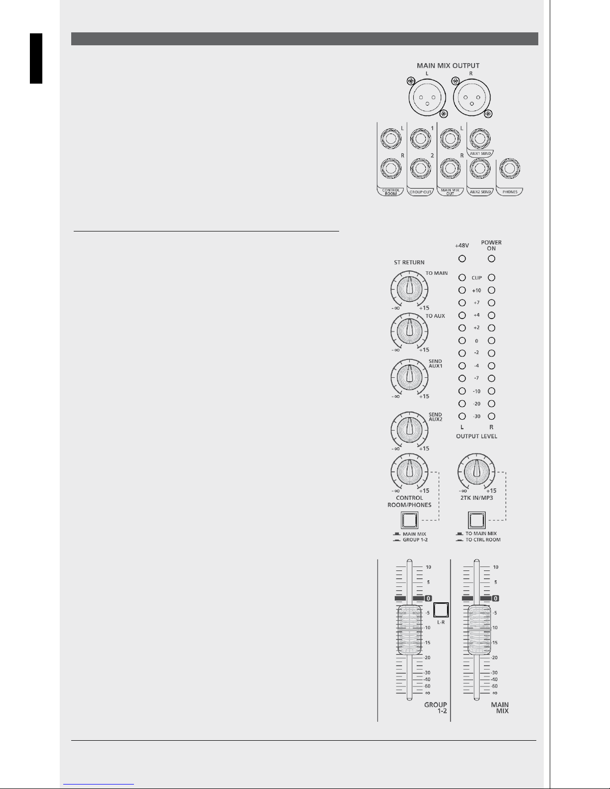
MAIN MIX output: XLR balanced male connectors. Plug in your active speakers or main
sound reinforcement system amplifier (for passive speakers) of here. The output level is
+4 dBu. This output is repeated on the TRS jack.
CONTROL ROOM output: Plug your studio monitor or local speakers into these TRS
jacks.
GROUP OUT output: TRS jacks. Plug in the lines to be routed to locations or devices
other than MAIN here.
AUX1 & AUX2 SENDS outputs: Plug a wedge stage monitor or external FX device into
these TRS jacks. The processed signal from the FX device is returned to the RCF mixing
consoles mixer via the Stereo Return jacks.
PHONES: TRS stereo jack, Tip = Left, Ring = Right, Sleeve = Common Earth. Plug in your
headphones here to listen to MAIN MIX or PFL when pressed.
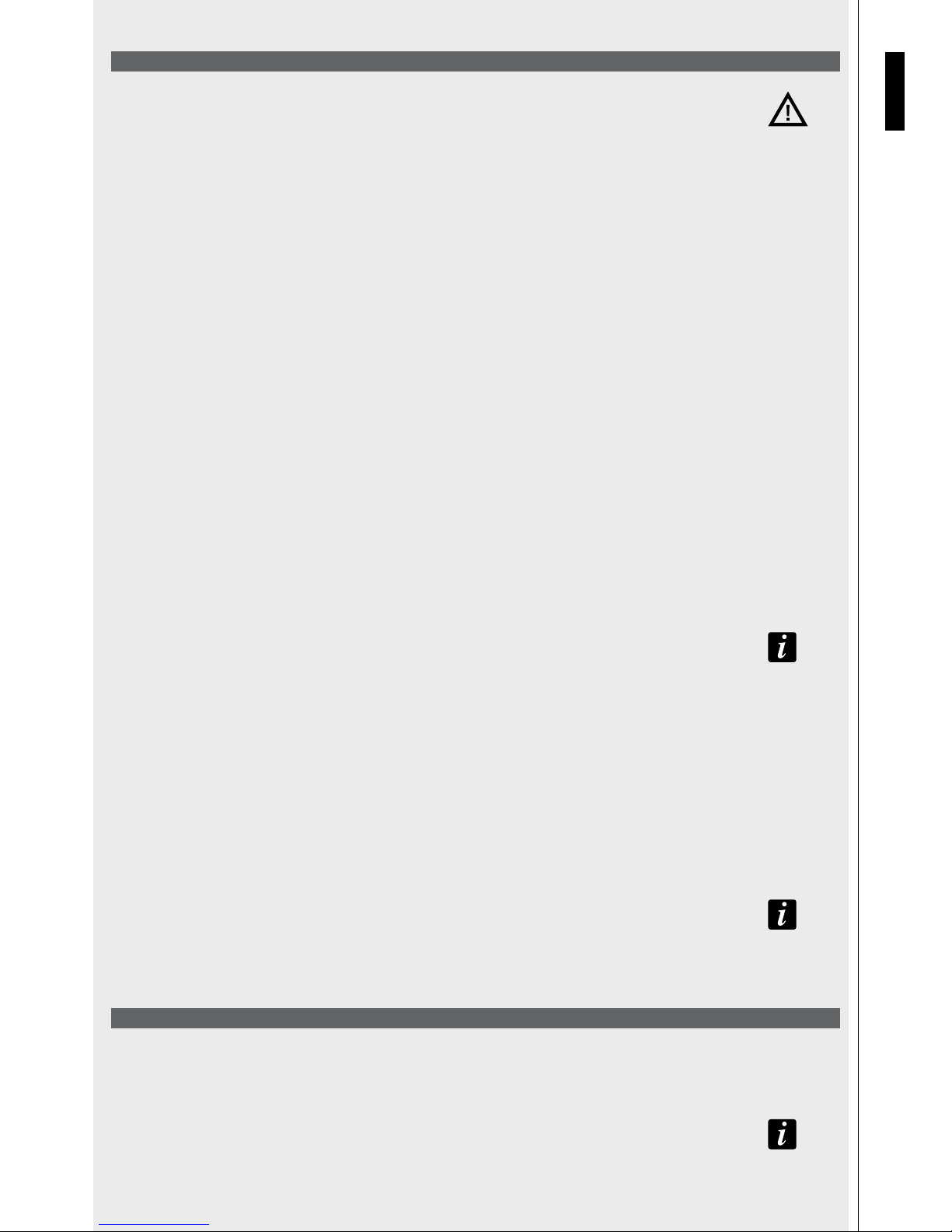
OUTPUT LEVEL: These LEDs show the MAIN MIX OUTPUT level.
Keep under CLIP level to prevent generating distorted sounds or dangerous sound levels.
ST RETURN control: This defines the STEREO RETURN input signal level routed to MAIN
MIX output.
TO AUX control: This defines the signal STEREO RETURN input level routed to AUX1
output.
SEND AUX1 control: This is the AUX1 send master level control.
SEND AUX2 control: This is the AUX2 send master level control.
CONTROL ROOM/PHONES control: This defines the signal level routed to CONTROL
ROOM output and PHONES output.
MAIN MIX-GROUP1-2 switch: In upper position allows you to listen the MAIN MIX
through the CONTROL ROOM speakers. When pressed, it allows to listen to GROUP1‑2
via the CONTROL ROOM speakers.
2TK IN/MP3 control: This defines the signal level from the 2TK IN input or from optional
cards (such as the RCF mixing consoles player, recorder or Bluetooth cards) routed to
MAIN MIX output.
TO MAIN MIX/TO CONTROL ROOM switch: Defines where to route the signal coming
from 2TK IN or optional cards: to MAIN MIX when in upper position, to CONTROL
ROOM when pressed (lower position).
FADER GROUP 1-2: GROUP 1‑2 signal level control. The GROUP 1‑2 signal is routed to
the MAIN MIX when the L‑R button is pressed.
FADER MAIN MIX: MAIN MIX output level control.
ENGLISH
Page 7

7
FUNCTIONS
ENGLISH
HOW TO IMPROVE THE SOUND
The RCF mixing consoles mixer implements several
powerful tools to improve the sound quality of your
music even more.
COMP: Turn the COMP control clockwise to add a compression effect to the signal. This allows to control the dynamic of the signal, limiting peaks and
gaining level in case of low signals.
EQ: A three‑band EQ is available on each mono channel, while a dual‑band
EQ is available on stereo channels 9‑10 and 11‑12. Adjust these parameters to
subtract noise frequencies or magnify desired sounds.
HOW TO GET SOUND FROM A RCF MIXER
1. Turn your RCF mixing consoles mixer on.
2. Set all the faders and controls to minimum position (0 or
‑∞)
3. Plug a microphone into the XLR connector ‑ MIC input of
channel 1.
4. Connect your speaker system to the MAIN MIX output and
turn it on.
5. Press the PFL button. Sing into the microphone and adjust
the GAIN control until the OUTPUT LEVEL is shown by means of LEDs (all green LEDs should light up and the first yellow LED should do so
occasionally).
6. Press again the PFL button to cancel the operation.
7. Adjust the FADER up to “0” position.
8. Check whether the MUTE button is in released (UN‑MUTED channel).
9. Press the L‑R button to route the channel signal to MAIN MIX.
10. Carefully turn up the MAIN MIX fader to reach a reasonable sound level.
11. Enjoy the quality of your RCF mixing consoles mixer.
Page 8

8
AVAILABLE ACCESSORIES
- RCF mixing consoles PLAYER Card: USB stick based MP3 Player Card – Max. capacity: 32 GB (p.n. 133 60 287)
-
RCF mixing consoles recorder card: USB flash drive based MP3 player/recorder card ‑ Max. capacity: 32 GB (p.n. 133 60 288)
- RCF mixing consoles Bluetooth card: Bluetooth connection card. This card allows to play your music playlist from Smartphone, Tablet or any Bluetooth
device. (p.n. 133 60 289)
MOUNT ACCESSORIES
- Rack ears (RCF Part Number: 133 60 292)
RCF mixing consoles OPTIONAL CARDS Installation and use
With the help of a small flat screwdriver press horizontally the plastic cover on its right side and remove it carefully.
To install a RCF mixing consoles Bluetooth card or a RCF mixing consoles player card, plug the 5 pin cable into the 5 pin connector on the PCB board as
shown.
To install a RCF mixing consoles player/recorder card, plug the 5 pin cable into the 5 pin connector and the 3 pin cable into the 3 pin connector on the
PCB board as shown.
Now place the optional card in its site and enjoy the new functions.
RCF mixing consoles BLUETOOTH CARD: Turn the Bluetooth interface on your mobile device on and press the PAIR button on the card. Your mobile device
will recognize the “BT2.1” Bluetooth device. Pair your device with the BT2.1 device. You can now play your favourite music.
Turn clockwise the knob named 2TK/MP3 up to 12 o’clock position and check if the TO MAIN MIX/TO CTRL ROOM switch is in upper position; now raise
carefully the MAIN MIX fader up to the desired listening level. You can adjust the volume on the card panel also pressing the buttons VOL+ and VOL‑.
RCF mixing consoles PLAYER CARD: from your computer, copy in a USB drive as many mp3 files as you want, even contained in folders (max 32 GB
total), insert the USB pen in the USB dedicated connector on the card, press and hold the PUSH&HOLD button for two seconds, the card will start to play
the first file of the first folder, the display will show alternatively the number of the file and the number of the folder which is playing. Press the “
” or
“
” button to skip to the previous or to the following track. Hold the same buttons pressed to change the selected folder. Use the PLAY/PAUSE button
to pause or restart playback. Press STOP to stop playback. Press the loop button (
) repeatedly to select random play, loop the current track or loop the
entire programme, respectively.
Turn clockwise the knob named 2TK/MP3 up to 12 o’clock position and check if the TO MAIN MIX/TO CTRL ROOM switch is in upper position; now raise
carefully the MAIN MIX fader up to the desired listening level.
RCF mixing consoles PLAYER/RECORDER CARD: from your computer, copy in a USB drive as many mp3 files as you want, even contained in folders (max
32 GB total). Insert the USB flash drive in the dedicated USB port on the card, press and hold the PUSH & HOLD button pressed for two seconds. The card
will start playing the first file in the first folder. The file number and folder number which is playing will be shown on the display. Press the “
” or “ ”
buttons to skip to the previous or to the following music file. Hold the same buttons pressed to change the selected folder. The card allows you to record
the program present on MAIN MIX: press the REC button once, now the board is in “rec ready status” and the display shows a flashing REC advise; press
REC again to start recording; press PUSH&HOLD button once for stop recording; the card will create a new folder on the USB pen called FrE01 where the
created files will find place. Use the PLAY/PAUSE button to pause or restart playback. Press the loop button (
) repeatedly to select random play, loop the
current track or loop the entire programme, respectively.
Turn clockwise the knob named 2TK/MP3 up to 12 o’clock position and check if the TO MAIN MIX/TO CTRL ROOM switch is in upper position; now raise
carefully the MAIN MIX fader up to the desired listening level.
OPTIONAL CARDS
Gently remove the
plastic cover with the
help of a screwdriver.
5 pin connector3 pin connector
Be sure to
connect each
connector in its
proper position.
Page 9
9
1. Leggere attentamente tutte le precauzioni, in particolare quelle relative alla sicurezza poiché forniscono informazioni importanti.
AVVERTENZA: al fine di evitare il rischio di incendio o di scossa elettrica, non esporre mai il prodotto alla pioggia o all’umidità.
2. ALIMENTAZIONE TRAMITE LA RETE ELETTRICA
a. La tensione della rete elettrica è sufficientemente elevata da provocare folgorazione; installare e collegare il dispositivo prima di
collegarlo alla rete di alimentazione.
b. Prima di accendere il dispositivo verificare che tutti i collegamenti siano stati effettuati in maniera corretta e che la tensione della
rete di alimentazione corrisponda al valore indicato nella targhetta dati dell’unità. In caso contrario rivolgersi al proprio rivenditore
RCF.
c. Le parti metalliche dell’unità sono collegate a terra attraverso il cavo di alimentazione. Questo è un dispositivo di CLASSE I e deve
essere collegato a una presa dotata di messa a terra.
d. Proteggere il cavo di alimentazione da possibili danneggiamenti; assicurarsi che sia posizionato in modo da non essere calpestato
o schiacciato da altri oggetti.
e. Onde evitare il rischio di scosse elettriche, non aprire mai il prodotto: esso non contiene parti a cui l’utente possa avere necessità
di accedere.
3. Evitare l’infiltrazione di corpi estranei o liquidi all’interno del dispositivo poiché potrebbero provocare un cortocircuito.
Il dispositivo non deve essere esposto a spruzzi o gocciolamenti. Non collocare sul dispositivo oggetti pieni di liquidi, per esempio vasi.
Non collocare sul dispositivo fiamme libere, per esempio candele.
4. Non tentare mai di eseguire operazioni, modifiche o riparazioni che non siano espressamente descritte in questo manuale.
Rivolgersi a un centro di assistenza autorizzato qualora dovesse verificarsi uno dei seguenti casi:
‑ Il dispositivo non funziona (o funziona in maniera anomala).
‑ Il cavo di alimentazione è danneggiato.
‑ Corpi estranei o liquidi sono penetrati nel dispositivo.
‑ Il dispositivo ha subito un impatto violento.
5. Scollegare il dispositivo in previsione di un periodo di inutilizzo prolungato.
6. Spegnere immediatamente il dispositivo e scollegarlo qualora si osservino emissioni di fumo o di odori anomali.
7. Non collegare il dispositivo ad apparecchiature o ad accessori diversi da quelli appositamente previsti.
Per installazioni sospese, utilizzare esclusivamente i punti di ancoraggio previsti. Non tentare di appendere il dispositivo servendosi di
elementi non idonei o di elementi non specificamente previsti per questo scopo. Verificare inoltre l’idoneità della superficie di supporto
a cui si intende ancorare il prodotto (parete, soffitto, struttura, ecc.) e dei componenti utilizzati per il fissaggio (tasselli, viti, staffe
non fornite da RCF, ecc.), che devono garantire la sicurezza del sistema/installazione nel tempo, considerando inoltre, per esempio, le
vibrazioni meccaniche normalmente prodotte dai trasduttori.
Onde evitare il rischio di cadute, evitare di sovrapporre più unità del dispositivo, a meno che il manuale specifichi tale possibilità.
8. RCF S.p.A. raccomanda vivamente di affidare l’installazione del prodotto esclusivamente a installatori professionali
qualificati (o a ditte specializzate) in grado di garantire la corretta installazione e di certificarla in base alle normative
in vigore. L’impianto audio deve essere complessivamente conforme agli standard e alle normative vigenti in materia
di impianti elettrici.
9. Supporti e carrelli
L’apparecchiatura deve essere utilizzata esclusivamente su carrelli o supporti del tipo raccomandato dal fabbricante, ove necessario.
L’apparecchiatura con il relativo supporto o carrello deve essere spostata con estrema cautela. Arresti improvvisi, spinte eccessivamente
forti e pavimentazioni irregolari possono provocare il ribaltamento dell’apparecchiatura.
10. Ai fini dell’installazione di un impianto audio professionale è necessario considerare numerosi fattori meccanici ed elettrici (oltre a
quelli prettamente acustici come la pressione sonora, gli angoli di copertura, la risposta in frequenza, ecc.).
11. Perdita dell’udito
L’esposizione a livelli sonori elevati può provocare perdita dell’udito permanente. Il livello di pressione sonora pericolosa per l’udito varia
sensibilmente da persona a persona e dipende dalla durata dell’esposizione. Per evitare esposizioni potenzialmente pericolose a livelli
elevati di pressione sonora è necessario fare uso di protezioni adeguate. Durante l’utilizzo di un trasduttore in grado di produrre livelli
elevati di pressione sonora è necessario indossare tappi o cuffie protettive per le orecchie. Per conoscere il livello massimo di pressione
sonora consultare i dati tecnici contenuti nel manuale delle istruzioni.
NOTE IMPORTANTI
- Al fine di prevenire la produzione di rumore sui cavi del segnale di linea, utilizzare esclusivamente cavi schermati ed evitare di
collocarli nelle vicinanze di:
- Apparecchiature che producono campi elettromagnetici ad alta intensità
- Cavi di alimentazione
- Linee degli altoparlanti
PRECAUZIONI D’USO
- Posizionare il dispositivo lontano da fonti di calore e assicurare sempre un’adeguata circolazione d’aria attorno ad esso.
- Non sottoporre il prodotto a sovraccarichi prolungati.
- Non forzare mai i comandi (pulsanti, manopole, ecc.).
- Non utilizzare solventi, alcool, benzene o altre sostanze volatili per la pulizia delle parti esterne del dispositivo.
NOTE IMPORTANTI
Prima di collegare e utilizzare il dispositivo, leggere attentamente questo manuale di istruzioni e conservarlo per consultazioni future.
Il manuale è parte integrante del dispositivo e deve seguirlo anche nei passaggi di proprietà per permettere al nuovo proprietario di
conoscere le modalità di installazione e d’uso e le avvertenze per la sicurezza. RCF S.p.A. declina ogni responsabilità per le conseguenze
di un’installazione e/o utilizzo errati del dispositivo.
IMPORTANTE
AVVERTENZE
NOTE
IMPORTANTI
ITALIANO
AVVERTENZE PER LA SICUREZZA
NOTE
IMPORTANTI
Page 10

10
INFORMAZIONI SUL DISPOSITIVO
Grazie per aver acquistato un mixer RCF mixing consoles.
L‑PAD 12C è un mixer audio versatile, dotato di tutti gli strumenti necessari per una corretta elaborazione di segnali audio multipli provenienti da diverse
sorgenti. Le funzionalità sono espandibili mediante l’aggiunta di schede opzionali che consentono di implementare funzioni di riproduzione/registrazione
audio MP3 o Bluetooth.
SUONO LIMPIDO
I dispositivi RCF mixing consoles combinano la “sound culture” professionale di RCF con l’innovazione del design e la fabbricazione dedicata. Le console
di mixaggio RCF mixing consoles garantiscono un suono limpido, dinamiche del suono accurate e un’estrema versatilità d’uso per utenti professionali
appassionati. I mixer RCF mixing consoles sono progettati per integrarsi in maniera ottimale con gli altoparlanti attivi RCF.
AFFIDABILITÀ
Durante la fabbricazione, tutti i mixer RCF mixing consoles sono sottoposti a quattro approfonditi test strumentali di qualità. Al termine della produzione
viene eseguito un test di ascolto, seguito da un controllo finale della qualità volto a individuare eventuali difetti visibili quali graffi o ammaccature. Questo
processo garantisce una straordinaria affidabilità e la massima qualità del dispositivo che avete appena acquistato.
DESIGN
L’esclusivo design dei mixer RCF mixing consoles è espressione della creatività RCF tipicamente italiana. I mixer RCF mixing consoles sono caratterizzati
da un moderno design ergonomico di eccellente livello. Oltre ad essere esteticamente gradevoli, gli originali profili laterali dei mixer li rendono facili da
impugnare in tutta sicurezza.
CARATTERISTICHE
Ingressi 6 ingressi MIC XLR/linea con connettore jack da ¼” (linee mono con insert 1, 2, 3, 4, linee stereo 5‑6, 7‑8)
4 compressori (C. 1 ‑ 4)
2 ingressi di linea stereo con connettore jack da ¼” (5‑6, 7‑8)
2 ingressi di linea stereo con connettore jack da ¼” o RCA
1 ingresso 2TK con RCA
1 ritorno stereo con connettore jack da ¼”
Uscite 1 uscita 2TK con RCA
1 uscita stereo MAIN MIX con XLR bilanciato e connettore jack da ¼”
1 uscita stereo CONTROL ROOM con connettore jack da ¼”
1 uscita stereo PHONES con connettore jack da ¼”
2 uscite AUX SEND con connettore jack da ¼”
Altre caratteristiche EQ a tre bande sui canali mono
EQ a due bande sui canali stereo 9‑10, 11‑12
2 AUX SEND
Slot per schede opzionali: scheda lettore MP3, scheda lettore/registratore MP3 (con porta USB 1.1 per USB flash drive fino a
32 GB), scheda per connessione Bluetooth
PSU interna da 100 V‑240 V, 50‑60 Hz, 40 W
Specifiche fisiche Dimensioni: LUNGH. = 480 mm, LARGH. = 340 mm, ALT. = 100 mm
Peso: 3,830 kg
FUNZIONI
Ingresso MIC (C. 1-C. 7/8) Consente di collegare i microfoni ai seguenti connettori XLR
bilanciati: pin1=Terra, pin2=Caldo, pin3=Freddo. Questi ingressi sono dotati di alimentazione
phantom a +48 V per microfoni a condensatore o a elettrete. Scala guadagno 0 dB/‑50 dB.
Ingresso LINE (C. 1-C. 4) Consente di collegare i dispositivi a segnale di linea ai seguenti
connettori TRS: punta=Caldo, anello=Freddo, manica=Terra. Questi ingressi sono indicati per
preamplificatori esterni o DI‑box. Scala guadagno +15 dB/‑35 dB.
INSERT (C. 1 - C. 4) Questi connettori TRS: punta=invio, anello=ritorno, manica=terra
comune consentono di inviare il segnale, attraverso una linea non bilanciata, a dispositivi
esterni (cioè un compressore) e di inviare nuovamente il segnale elaborato al canale.
GAIN (C. 1 - C. 6) Controlla il guadagno del livello (0 dB/‑50 dB per l’ingresso linea del
microfono e +15 dB/‑35 dB per l’ingresso linea quando utilizzata).
Pulsante LOW CUT Se premuto, consente di ridurre le frequenze al di sotto dei 75 Hz con
una pendenza di 12 dB/ott. Si tratta di una funzione utile per prevenire i rimbombi durante
l’uso dei microfoni.
ITALIANO
COMP (C. 1 - C. 4) Un unico potenziometro controlla sia
la soglia del compressore sia il rapporto di compressione.
Page 11

11
FUNZIONI
INGRESSO STEREO LINE (C. 5/6 - C.11/12) Consente di collegare una tastiera o dispositivi a segnale di linea stereo. Scala guadagno +15 dB/‑35 dB
(C. 5/6 ‑ C. 7/8). Durante l’uso degli ingressi MIC 5‑6 o 7‑8, i canali corrispondenti funzionano come canali mono.
STEREO RETURN Collega i segnali provenienti da dispositivi esterni, per
esempio moduli FX, a questi connettori TRS non bilanciati.
Ingresso RCA LINE (C. 9/10 - C.11/12) Consente di collegare dispositivi a basso livello e dispositivi commerciali
come lettori CD, computer o telefoni cellulari (è necessario un adattatore).
2TK IN – 2TK OUT Questi connettori RCA non
bilanciati sono indicati per il collegamento di
dispositivi di riproduzione e registrazione audio.
ITALIANO
EQ: per i canali mono è disponibile una funzione di EQ
a tre bande:
HI = ±15 dB a 12 kHz
MID = ±15 dB a 2,5 kHz
LOW = ±15 dB a 80 Hz
EQ a due bande per i canali stereo:
HI = ±15 dB a 12 kHz
LOW = ±15 dB a 80 Hz
AUX1: comando di mandata ausiliario, livello da ‑∞
a +15 dB. Il segnale viene inviato al connettore jack
dell’uscita AUX1 SEND. La funzione POST/PRE determina
se estrarre il segnale secondo la posizione del fader o
indipendentemente da essa.
Pulsante PRE/POST: rilasciando il pulsante, il segnale
viene estratto in posizione pre‑fader (indipendentemente
dal livello del fader); premendo il pulsante, il segnale viene estratto dalla posizione post‑fader (il livello di invio dipende dal livello del fader).
AUX2: comando di mandata ausiliario, livello da ‑∞ a +15 dB. Il segnale viene inviato al connettore jack dell’uscita AUX2 SEND. Il segnale viene estratto in
posizione post‑fader.
PAN o PAN/BAL: definisce la posizione del segnale
nell’immagine stereo in caso di canale MONO o il
bilanciamento tra sinistra e destra in caso di canale
STEREO.
Pulsante MUTE: premere questo pulsante (LED rosso
acceso) per silenziare il canale.
Pulsante PFL: premere questo pulsante per ascoltare il
segnale attraverso l’uscita PHONES o CONTROL ROOM,
anche quando il fader è in posizione ‑∞ o silenziato.
Questa funzione è utile per verificare il livello di ingresso
del canale (vedere l’indicatore del LIVELLO DI USCITA).
Pulsante GROUP 1-2: premere questo pulsante per
inviare il segnale del canale all’uscita audio del gruppo
1‑2. In questo caso, il controllo di posizione PAN/BAL
definisce la quantità di segnale da inviare a GROUP 1
o GROUP 2.
Pulsante L-R: premere questo pulsante per inviare il
segnale del canale all’uscita MAIN MIX.
FADER C. 1 - C. 4: controllo del livello dei canali MONO
FADER C. 5/6 - C. 7/8: controllo del livello dei canali MONO/STEREO
FADER C. 9/10 - C. 11/12: controllo del livello dei canali STEREO
Page 12

12
FUNZIONI
Uscita MAIN MIX: connettori XLR maschio bilanciati. Consente di collegare gli
altoparlanti attivi o l’amplificatore del sistema principale di rinforzo sonoro (per
altoparlanti passivi). Il livello di uscita è +4 dBu. Questa uscita è ripetuta sul connettore
TRS.
Uscita CONTROL ROOM: collegare degli studio monitor o degli altoparlanti locali a
questi connettori TRS.
Uscita GROUP OUT: connettori TRS. Consente di collegare le linee da inviare a posizioni
o dispositivi diversi da MAIN.
Uscite AUX1 SEND e AUX2 SEND: collegare un monitor da palco o un dispositivo FX
esterno a questi connettori TRS. Il segnale elaborato proveniente dal dispositivo FX viene
rinviato al mixer RCF mixing consoles attraverso i connettori jack STEREO RETURN.
PHONES: connettore TRS stereo, Punta = Sinistra, Anello = Destra, Manica = Terra
comune. Collegare le cuffie a questo connettore jack per ascoltare MAIN MIX o PFL
se premuti.
LIVELLO DI USCITA: questi LED indicano il livello di uscita MAIN MIX.
Mantenere al di sotto del livello CLIP per evitare di produrre distorsioni del suono o
livelli sonori pericolosi.
Controllo ST RETURN: definisce il livello del segnale di ingresso STEREO RETURN
diretto all’uscita MAIN MIX.
Controllo TO AUX: definisce il livello del segnale di ingresso STEREO RETURN diretto
all’uscita AUX1.
Controllo SEND AUX1: è il controllo del livello master di mandata AUX1.
Controllo SEND AUX2: è il controllo del livello master di mandata AUX2.
Controllo CONTROL ROOM/PHONES: definisce il livello del segnale diretto alle uscite
CONTROL ROOM e PHONES.
Commutatore MAIN MIX-GROUP 1-2: se impostato nella posizione superiore consente
di ascoltare il segnale MAIN MIX attraverso gli altoparlanti CONTROL ROOM. Se premuto,
consente di ascoltare il segnale GROUP 1‑2 attraverso gli altoparlanti CONTROL ROOM.
Controllo 2TK IN/MP3: definisce il livello del segnale dall’ingresso 2TK IN o da schede
opzionali (lettore o registratore RCF mixing consoles, o Bluetooth) inviato all’uscita
MAIN MIX.
Commutatore TO MAIN MIX/TO CONTROL ROOM: definisce la direzione del segnale
proveniente da 2TK IN o da schede opzionali: verso MAIN MIX se in posizione alzata,
verso CONTROL ROOM se premuto (posizione abbassata).
FADER GROUP 1-2: controllo del livello del segnale GROUP 1‑2. Quando il pulsante L‑R
è premuto, il segnale GROUP 1‑2 viene inviato al MAIN MIX.
FADER MAIN MIX: controllo del livello dell’uscita MAIN MIX.
ITALIANO
Page 13

13
FUNZIONI
ITALIANO
COME MIGLIORARE IL SUONO
Il mixer RCF mixing consoles implementa numerosi
strumenti di grande potenza volti a migliorare
ulteriormente la qualità audio della musica.
COMP: ruotare il controllo COMP in senso orario per aggiungere al segnale un effetto di compressione. Ciò consente di controllare i picchi di segnale e di
aumentare il livello dei segnali più deboli.
EQ: su ciascun canale mono è disponibile un EQ a tre bande, mentre un EQ
a due bande è disponibile sui canali stereo 9‑10 e 11‑12. Regolare questi
parametri per rimuovere le frequenze indesiderate o amplificare le sfumature
piacevoli del suono.
COME OTTENERE L’AUDIO DA UN MIXER RCF
1. Accendere il mixer RCF mixing consoles.
2. Impostare tutti i fader e i controlli sulla posizione minima
(0 o ‑∞).
3. Collegare un microfono al connettore XLR ‑ ingresso MIC
del canale 1.
4. Collegare l’impianto degli altoparlanti all’uscita MAIN
MIX e accenderlo.
5. Premere il pulsante PFL. Cantare nel microfono e regolare
il controllo GAIN fino a visualizzare il LIVELLO DI USCITA per mezzo dei LED (tutti i LED di colore verde devono accendersi e a volte possono
accendersi i primi LED di colore giallo).
6. Premere nuovamente il pulsante PFL per annullare l’operazione.
7. Regolare il FADER fino alla posizione “0”.
8. Verificare se il pulsante MUTE è rilasciato (canale UN‑MUTED).
9. Premere il pulsante L‑R per inviare il segnale del canale al MAIN MIX.
10. Alzare con cautela il fader di MAIN MIX fino a raggiungere un livello sonoro accettabile.
11. Apprezzare la qualità del mixer RCF mixing consoles.
Page 14

14
ACCESSORI DISPONIBILI
- Scheda RCF mixing consoles PLAYER: scheda lettore MP3 su unità USB – Max. capacità: 32 GB (cod.: 133 60 287)
-
Scheda RCF mixing consoles PLAYER/RECORDER: scheda lettore/registratore MP3 su unità USB ‑ Max. capacità: 32 GB
(cod.: 133 60 288)
- Scheda RCF mixing consoles BLUETOOTH: scheda di connessione Bluetooth. Questa scheda consente di riprodurre le proprie playlist
musicali da Smartphone, Tablet o qualsiasi dispositivo Bluetooth. (cod.: 133 60 289)
ACCESSORI DI MONTAGGIO
- Kit per montaggio a rack (cod.: 133 60 292)
SCHEDE OPZIONALI
SCHEDE OPZIONALI RCF mixing consoles Installazione e uso
Con l’ausilio di un piccolo cacciavite a punta piatta, premere orizzontalmente il coperchio di plastica sul lato destro e rimuoverlo con cautela.
Per installare una scheda Bluetooth RCF mixing consoles o una scheda lettore RCF mixing consoles, collegare il cavo a 5 pin al connettore a 5 pin presente
sulla scheda del PCB, come illustrato.
Per installare una scheda lettore/registratore RCF mixing consoles, collegare il cavo a 5 pin al connettore a 5 pin e il cavo a 3 pin al connettore a 3 pin
presenti sulla scheda del PCB, come illustrato.
A questo punto montare la scheda opzionale nell’apposita sede ed esplorare le nuove funzioni.
SCHEDA BLUETOOTH RCF mixing consoles: attivare l’interfaccia Bluetooth del dispositivo mobile e premere il pulsante PAIR della scheda. Il dispositivo
mobile riconosce il dispositivo Bluetooth “BT2.1”. Associare il dispositivo al dispositivo BT2.1. A questo punto è possibile riprodurre la propria musica
preferita.
Ruotare in senso orario la manopola 2TK/MP3 portandola sulla posizione “ore 12” e verificare che il commutatore TO MAIN MIX/TO CTRL ROOM si trovi
nella posizione superiore; a questo punto sollevare con cautela il fader MAIN MIX fino al livello di ascolto desiderato. Per regolare il volume sul pannello
della scheda è possibile anche premere i pulsanti VOL+ e VOL‑.
SCHEDA LETTORE RCF mixing consoles: dal computer, copiare tutti i file mp3 desiderati in un’unità USB, anche organizzati in cartelle (fino a un massimo
di 32 GB). Inserire l’unità USB nell’apposito connettore presente sulla scheda, tenere premuto il pulsante PUSH&HOLD per due secondi. La scheda inizia
a riprodurre il primo file della prima cartella. Il display visualizza alternativamente il numero del file e il numero della cartella in riproduzione. Premere il
pulsante “
” o “ ” per passare al brano precedente o a quello successivo. Tenere premuti gli stessi pulsanti per cambiare cartella. Utilizzare il pulsante
PLAY/PAUSE per sospendere o riavviare la riproduzione. Premere STOP per interrompere la riproduzione. Premere ripetutamente il pulsante “loop” (
) rispettivamente per selezionare la riproduzione casuale, riprodurre a ciclo continuo il brano corrente o riprodurre a ciclo continuo l’intero programma.
Ruotare in senso orario la manopola 2TK/MP3 portandola sulla posizione “ore 12” e verificare che il commutatore TO MAIN MIX/TO CTRL ROOM si trovi
nella posizione superiore; a questo punto sollevare con cautela il fader MAIN MIX fino al livello di ascolto desiderato.
SCHEDA LETTORE/REGISTRATORE RCF mixing consoles: dal computer, copiare tutti i file mp3 desiderati in un’unità USB, anche organizzati in cartelle
(fino a un massimo di 32 GB). Inserire l’unità USB nell’apposito connettore presente sulla scheda, tenere premuto il pulsante PUSH&HOLD per due secondi.
La scheda inizia a riprodurre il primo file della prima cartella. Il display visualizza il numero del file e il numero della cartella in riproduzione. Premere il
pulsante “
” o “ ” per passare al file musicale precedente o a quello successivo. Tenere premuti gli stessi pulsanti per cambiare cartella. La scheda
consente di registrare il programma presente in MAIN MIX: premere una volta il pulsante REC, a questo punto la scheda si trova in modalità “rec ready”
(“pronto per la registrazione”) e il display visualizza l’indicazione REC lampeggiante; premere nuovamente REC per iniziare la registrazione; premere una
volta il pulsante PUSH&HOLD per interrompere la registrazione; la scheda crea una nuova cartella nell’unità USB, chiamata FrE01 in cui saranno collocati i
file creati. Utilizzare il pulsante PLAY/PAUSE per sospendere o riavviare la riproduzione. Premere ripetutamente il pulsante “loop” (
) rispettivamente per
selezionare la riproduzione casuale, riprodurre a ciclo continuo il brano corrente o riprodurre a ciclo continuo l’intero programma.
Ruotare in senso orario la manopola 2TK/MP3 portandola sulla posizione “ore 12” e verificare che il commutatore TO MAIN MIX/TO CTRL ROOM si trovi
nella posizione superiore; a questo punto sollevare con cautela il fader MAIN MIX fino al livello di ascolto desiderato.
ITALIANO
Rimuovere
con cautela il
coperchio di
plastica per
mezzo di un
cacciavite.
Connettore a 5 pinConnettore a 3 pin
Assicurarsi di
collegare ogni
connettore
nella posizione
corretta.
Page 15

15
1. Lisez très attentivement tous les avertissements, notamment ceux portant sur la sécurité, car ils fournissent des informations importantes.
AVERTISSEMENT : afin de prévenir tout risque d‘incendie ou de choc électrique, n‘exposez jamais ce produit à la pluie ou à l‘humidité.
2. ALIMENTATION SUR SECTEUR
a. La tension secteur est suffisamment élevée pour provoquer une électrocution. Installez et connectez l‘appareil avant de le brancher.
b. Avant la mise sous tension, vérifiez que toutes les connexions ont été correctement effectuées et que la tension secteur correspond à la
tension indiquée sur la plaque d‘identification de l‘appareil. Contactez votre revendeur RCF si ce n‘est pas le cas.
c. Les parties métalliques de l‘appareil sont reliées à la terre via le câble d‘alimentation. L‘appareil est de CLASSE I et doit être branché
sur une prise reliée à la terre.
d. Protégez le câble d‘alimentation de tout dommage ; vérifiez qu‘il est placé de telle sorte qu‘il ne soit pas piétiné ou écrasé par des objets.
e. Afin de prévenir tout risque de choc électrique, n‘ouvrez jamais le produit : l‘utilisateur n‘a besoin d‘accéder à aucune des pièces qui y
sont contenues.
3. Veillez à ce qu‘aucun objet ou liquide ne pénètre dans l‘appareil, car cela pourrait provoquer un court‑circuit.
L‘appareil ne doit pas être exposé aux gouttes ou aux éclaboussures. Ne placez sur l‘appareil aucun récipient rempli de liquide, tel qu‘un vase.
Ne placez sur l‘appareil aucun objet enflammé, tel qu‘une bougie allumée.
4. Ne tentez jamais d‘effectuer des interventions, des modifications ou des réparations non expressément décrites dans ce manuel.
Contactez votre centre de réparation agréé ou un technicien qualifié dans les cas suivants :
‑ L‘appareil ne fonctionne pas (ou fonctionne de façon anormale).
‑ Le câble d‘alimentation est endommagé.
‑ Des objets ou des liquides se sont introduits dans l‘appareil.
‑ L‘appareil a subi un choc violent.
5. Débranchez l‘appareil s‘il n‘est pas utilisé sur une longue période.
6. Éteignez immédiatement l‘appareil et débranchez‑le en cas d‘émanation de fumée ou d‘odeurs inhabituelles.
7. Ne connectez pas l‘appareil à un équipement ou à des accessoires différents de ceux fournis à cet effet.
Si vous suspendez l‘appareil, utilisez uniquement les points d‘ancrage prévus à cet effet. N‘essayez pas d‘accrocher l‘appareil au moyen
d‘éléments inappropriés ou non conçus pour cet usage. Vérifiez également l‘adéquation de la surface d‘ancrage du produit (mur, plafond,
structure, etc.) et des éléments utilisés pour la fixation (chevilles, vis, crochets non fournis par RCF, etc.). Cette vérification est indispensable
pour garantir la sécurité du système et de l‘installation au cours du temps. Par ailleurs, tenez compte des vibrations mécaniques habituellement
générées par les haut‑parleurs.
Afin de prévenir tout risque de chute, n‘empilez pas plusieurs appareils sauf si une telle possibilité est spécifiquement mentionnée dans le
manuel utilisateur.
8. RCF S.p.A. recommande vivement de faire installer ce produit par des installateurs professionnels qualifiés (ou des
entreprises spécialisées) qui peuvent garantir une installation correcte et la certifier par rapport à la réglementation en
vigueur.
L‘ensemble du système audio doit être conforme à la réglementation et aux normes relatives aux systèmes électriques.
9. Supports et chariots
Le produit doit être utilisé uniquement sur des chariots ou des supports recommandés par le fabricant, en cas de besoin. L‘ensemble produit/
support/chariot doit être déplacé avec la plus grande attention. Les arrêts brusques, les poussées excessives et les sols inégaux peuvent
provoquer le renversement de l‘installation.
10. De nombreux facteurs mécaniques et électriques sont à prendre en compte lors de l‘installation d‘un système audio professionnel (en plus
des facteurs purement acoustiques tels que la pression sonore, les angles de détection, la réponse en fréquence, etc.).
11. Pertes d‘audition
L‘exposition à des niveaux sonores élevés peut entraîner des pertes d‘audition définitives. Le niveau de pression sonore qui entraîne des pertes
d‘audition varie d‘une personne à l‘autre et dépend du temps d‘exposition. Des équipements de protection appropriés doivent être utilisés afin
de prévenir une exposition potentiellement dangereuse aux niveaux élevés de pression sonore. Des bouchons d‘oreille ou des protège‑oreilles
doivent être portés en cas d‘utilisation d‘un haut‑parleur susceptible de produire des niveaux sonores élevés. Reportez‑vous aux spécifications
techniques de ce manuel pour connaître le niveau maximal de pression sonore.
REMARQUES IMPORTANTES
- Afin de prévenir l‘apparition de bruit sur les câbles de signal, utilisez uniquement des câbles blindés et évitez de les placer à côté des
équipements suivants :
- appareils générateurs de champs magnétiques de haute intensité ;
- câbles d‘alimentation ;
- lignes de haut‑parleur.
PRÉCAUTIONS D’UTILISATION
- Éloignez l‘appareil des sources de chaleur et veillez toujours à assurer une circulation d‘air suffisante autour de lui.
- Ne surchargez pas l‘appareil sur une longue période.
- Ne forcez jamais les commandes (boutons, potentiomètres, etc.).
- N‘utilisez pas de solvants, d‘alcool, de benzène ni d‘autres substances volatiles pour le nettoyage des surfaces extérieures de l‘appareil.
REMARQUES IMPORTANTES
Veuillez lire ce manuel d‘utilisation avec attention et gardez‑le à portée de main pour consultation ultérieure avant de connecter et d‘utiliser
l‘appareil. Ce manuel est un composant du produit à part entière et, en cas de changement de propriétaire, il doit l‘accompagner en tant que
document de référence pour l‘installation, l‘utilisation et les consignes de sécurité. RCF S.p.A. décline toute responsabilité en cas d‘installation
et/ou d‘utilisation incorrecte de l‘appareil.
IMPORTANT
AVERTISSEMENTS
REMARQUES
IMPORTANTES
FRANÇAIS
CONSIGNES DE SÉCURITÉ
REMARQUES
IMPORTANTES
Page 16

16
INFORMATIONS RELATIVES À L’APPAREIL
Nous vous remercions d‘avoir acheté le mélangeur RCF RCF mixing consoles.
Le L‑PAD12C est un mélangeur audio polyvalent, doté de tous les outils nécessaires au traitement de multiples signaux audio issus de différentes sources.
Ses capacités peuvent être étendues par l‘ajout de cartes optionnelles permettant d‘implémenter un lecteur/enregistreur MP3 ou des fonctions Bluetooth.
PURETÉ DU SON
Les produits RCF mixing consoles allient la tradition professionnelle de RCF en matière de « culture du son » avec une conception innovante et une
fabrication spécialisée. Les consoles de mixage RCF mixing consoles garantissent une pureté du son, une dynamique sonore précise ainsi qu‘une extrême
flexibilité d‘utilisation pour les professionnels passionnés de son. Les mélangeurs RCF mixing consoles sont conçus pour fonctionner parfaitement avec les
haut‑parleurs actifs RCF.
FIABILITÉ
Tous les mélangeurs RCF mixing consoles subissent des tests approfondis de qualité instrumentale lors de leur fabrication. Un test d‘écoute est mené en fin
de fabrication, puis un contrôle d‘inspection final est effectué afin de détecter tout défaut d‘aspect tel qu‘une éraflure ou un coup. Ce processus garantit
une fiabilité exceptionnelle et permet de s‘assurer du très haut niveau de qualité de l‘appareil que vous avez acheté.
DESIGN
La conception unique des mélangeurs RCF mixing consoles symbolise la créativité italienne caractéristique de RCF. Les mélangeurs RCF mixing consoles
bénéficient d‘un excellent design, à la fois moderne et ergonomique. En plus de leur aspect remarquable, le profil original des mélangeurs permet de les
prendre en main aisément et en toute sécurité.
CARACTÉRISTIQUES
Entrées 6 entrées linéaires/MIC XLR avec jack 6,35 mm (lignes mono 1, 2, 3, 4 avec insertions de lignes stéréo 5‑6 et 7‑8)
4 compresseurs (Can. 1 ‑ Can. 4)
2 entrées de ligne stéréo avec jack 6,35 mm (3‑4, 5‑6)
2 entrées de ligne stéréo avec jack 6,35 mm ou prise RCA
1 entrée 2TK avec prise RCA
1 retour stéréo avec jack 6,35 mm
Sorties 1 sortie 2TK avec prise RCA
1 sortie stéréo MAIN MIX avec XLR équilibré et jack 6,35 mm
1 sortie stéréo CONTROL ROOM avec jack 6,35 mm
1 sortie stéréo PHONES avec jack 6,35 mm
2 sorties AUX SEND avec jack 6,35 mm
Autres caractéristiques 1 égaliseur tri‑bande sur les canaux mono
1 égaliseur bi‑bande sur les canaux stéréo 9‑10 et 11‑12
2 contrôles AUX SEND
Emplacement pour carte optionnelle : Carte lecteur MP3, carte lecteur/enregistreur MP3 (avec port USB 1.1
pour clé USB de capacité maximale 32 Go), carte de connexion Bluetooth
Bloc d’alimentation interne 100‑240 V, 50‑60 Hz, 40 W
Spécifications physiques Dimensions : Long. = 480 mm, Larg. = 340 mm, Haut. = 100 mm
Poids : 3,830 kg
FONCTIONS
Entrée MIC (Can. 1 - Can. 7/8) Connectez vos micros aux connecteurs XLR équilibrés
suivants : Broche 1 = Terre, Broche 2 = Point chaud, Broche 3 = Point froid. Ces entrées sont
fournies avec une alimentation fantôme de +48 V pour les microphones à condensateur ou
à électret Échelle de gain 0 dB/‑50 dB
Entrée LINE (Can. 1 - Can. 4) Connectez vos appareils de niveau de ligne aux connecteurs
jack TRS suivants : Pointe = Point chaud, Anneau = Point froid, Gaine = Terre. Ces entrées sont
adaptées aux pré‑amplificateurs externes et aux boîtes DI. Échelle de gain +15 dB/‑35 dB
INSERT (Can. 1 - Can. 4) Les connecteurs TRS suivants : Pointe = Envoi, Anneau = Retour,
Gaine = Terre, permettent d‘envoyer le signal sur des appareils externes (compresseurs, p.
ex.) via une ligne non équilibrée et de retourner dans le canal le signal traité.
GAIN (Can. 1 - Can. 6) Permet de contrôler le niveau de gain (0 dB/‑50 dB pour l‘entrée MIC
et +15 dB/‑35 dB pour l‘entrée LINE lors de leur utilisation).
Interrupteur LOW CUT : en appuyant sur ce bouton, vous provoquerez la coupure des
fréquences inférieures à 75 Hz avec une pente de 12 dB/oct. Vous pourrez ainsi éliminer les
bourdonnements qui apparaissent lors de l‘utilisation de micros.
FRANÇAIS
COMP (Can. 1 - Can. 4) Un seul potentiomètre permet
de contrôler le seuil et le taux de compression.
Page 17

17
FONCTIONS
Entrée STEREO LINE (Can. 5/6 - Can. 11/12) Permet de brancher le clavier et les équipements stéréo ou de niveau de ligne. Échelle de gain +15 dB/‑35 dB
(Can. 5/6 ‑ Can. 7/8). Le canal correspondant fonctionne comme un canal mono lorsque l‘entrée MIC 5‑6 ou 7‑8 est utilisée.
STEREO RETURN Permet de connecter les signaux issus d‘appareils
externes (modules FX, p.ex.) à ces jacks TRS non équilibrés.
Entrée RCA LINE (Can. 9/10 - Can. 11/12) Permet de brancher les équipements bas de gamme ou grand public,
tels que les lecteurs de CD, les ordinateurs et les téléphones mobiles (adaptateur requis).
2TK IN – 2TK OUT Ces connecteurs RCA non équilibrés
sont adaptés pour la connexion des lecteurs et
enregistreurs audio.
FRANÇAIS
EQ : Un égaliseur tri‑bande est disponible pour les
canaux mono :
HI (aigus) = ±15 dB à 12 kHz
MID (médiums) = ±15 dB à 2,5 kHz
LOW (graves) = ±15 dB à 80 Hz
Un égaliseur bi‑bande est disponible pour les canaux
stéréo :
HI (aigus) = ±15 dB à 12 kHz
LOW (graves) = ±15 dB à 80 Hz
AUX1 Départ auxiliaire (niveau : ‑∞ à +15 dB). Le
signal est transmis vers le jack de sortie AUX SEND. La
fonction POST/PRE détermine s‘il faut extraire le signal
d‘après la position du fader ou indépendamment de
celui‑ci.
Bouton PRE/POST : Lorsque ce bouton est
relâché, le signal est extrait en position pré‑fader
(indépendamment du niveau du fader). Lorsqu‘il est enfoncé, le signal est extrait en position post‑fader (le niveau d‘émission dépend du niveau du fader).
AUX2 : Départ auxiliaire (niveau : ‑∞ à +15 dB). Le signal est transmis vers le jack de sortie AUX2 SEND. Le signal est extrait en position post‑fader.
PAN ou PAN/BAL : Ce contrôle définit la position
du signal dans l‘image stéréo dans le cas d‘un canal
MONO, et définit l‘équilibre entre la gauche et la droite
dans le cas d‘un canal STEREO.
Bouton MUTE : Appuyez sur ce bouton (LED rouge
allumée) pour couper le son du canal.
Bouton PFL : Appuyez sur ce bouton pour écouter
le signal sur la sortie PHONES même si le fader est
en position ‑∞ ou est coupé. Cette fonction permet
de vérifier le niveau d‘entrée du canal (cf. indicateur
OUTPUT LEVEL).
Bouton GROUP 1-2 : Appuyez sur ce bouton pour
transmettre le signal du canal vers la sortie audio
GROUP 1‑2. Dans ce cas, le contrôle de position PAN/
BAL définit la quantité de signal transmis vers GROUP 1
ou GROUP 2.
Bouton L-R : Appuyez sur ce bouton pour transmettre le signal du canal
vers la sortie MAIN MIX.
FADERS (Can. 1 - Can. 4) : Contrôle du niveau des canaux MONO
FADERS (Can. 5/6 - Can. 7/8) : Contrôle du niveau des canaux MONO/
STEREO
FADERS (Can. 9/10 - Can. 11/12) : Contrôle du niveau des canaux STEREO
Page 18

18
FONCTIONS
Sortie MAIN MIX : Ensemble de connecteurs équilibrés XLR mâles. Permet de brancher
les haut‑parleurs actifs ou l‘amplificateur audio principal (pour les haut‑parleurs passifs).
Le niveau de sortie est de +4 dBu. Cette sortie est réémise sur le jack TRS.
Sortie CONTROL ROOM : Branchez sur ces jacks TRS votre moniteur de studio ou vos
haut‑parleurs locaux.
Sortie GROUP OUT : Branchez sur ces jacks TRS les lignes à acheminer vers les
emplacements ou les appareils différents de MAIN.
Sorties AUX1 et AUX2 SEND : Branchez un moniteur « wedge » de scène ou un
appareil FX externe sur ces jacks TRS. Le signal issu de l‘appareil FX est renvoyé après
traitement sur le mélangeur RCF mixing consoles via les jacks STEREO RETURN.
PHONES : Jack TRS stéréo, Pointe = Gauche, Anneau = Droit, Gaine = Terre. Ce contrôle
permet de brancher des écouteurs afin d‘écouter les sorties MAIN MIX ou PFL lorsqu‘il
est appuyé.
OUTPUT LEVEL : Ces LED indiquent le niveau de sortie MAIN MIX.
Maintenez un niveau inférieur au niveau de saturation pour éviter de générer des
distorsions ou des niveaux sonores dangereux.
Contrôle ST RETURN : Permet de définir le niveau du signal d‘entrée STEREO RETURN
transmis vers la sortie MAIN MIX.
Contrôle TO AUX : Permet de définir le niveau du signal d‘entrée STEREO RETURN
transmis vers la sortie AUX1.
Contrôle SEND AUX1 : Contrôle de niveau principal AUX1 SEND.
Contrôle SEND AUX2 : Contrôle de niveau principal AUX2 SEND.
Contrôle CONTROL ROOM/PHONES : Permet de définir le niveau du signal transmis
vers les sorties CONTROL ROOM et PHONE.
Interrupteur MAIN MIX-GROUP 1-2 : En position haute, permet d‘écouter la sortie
MAIN MIX via les haut‑parleurs CONTROL ROOM. Lorsqu‘il est enfoncé, permet
d‘écouter la sortie GROUP 1‑2 via les haut‑parleurs CONTROL ROOM.
Contrôle 2TK IN/MP3 : Permet de définir le niveau du signal issu de l‘entrée 2TK IN
ou de cartes optionnelles (telles que le lecteur‑enregistreur RCF mixing consoles ou les
cartes Bluetooth) transmis vers la sortie MAIN MIX.
Interrupteur TO MAIN MIX/TO CONTROL ROOM : Permet de définir la sortie vers
laquelle doit être transmis le signal issu de l‘entrée 2TK IN ou des cartes optionnelles :
MAIN MIX lorsque cet interrupteur est en position haute, CONTROL ROOM lorsqu‘il est
enfoncé (en position basse).
FADER GROUP 1-2 : Contrôle du niveau du signal GROUP 1‑2. Le signal GROUP 1‑2 est
transmis vers la sortie MAIN MIX lorsque le bouton L‑R est enfoncé.
FADER MAIN MIX : Contrôle du niveau de sortie MAIN MIX.
FRANÇAIS
Page 19

19
FONCTIONS
FRANÇAIS
COMMENT AMÉLIORER LE SON
Le mélangeur RCF RCF mixing consoles est doté de
plusieurs outils puissants, destinés à améliorer encore
davantage la qualité sonore de vos musiques.
COMP : Tournez le contrôle COMP dans le sens des aiguilles d‘une montre pour ajouter un effet de compression au signal. Vous pouvez ainsi contrôler le
pic de limite du canal et améliorer la dynamique dans les graves.
EQ : Un égaliseur tri‑bande est disponible sur chaque canal mono, et un
égaliseur bi‑bande est disponible sur les canaux stéréo 9‑10 et 11‑12. Réglez
ces paramètres afin d‘éliminer les fréquences de bruit ou d‘amplifier les sons
souhaités.
COMMENT OBTENIR UN SIGNAL SONORE
DEPUIS UN MÉLANGEUR RCF mixing consoles
1. Allumez votre mélangeur RCF RCF mixing consoles.
2. Réglez l‘ensemble des faders et des contrôles sur leur
position minimale (0 ou ‑∞).
3. Branchez un micro sur le connecteur XLR ‑ entrée MIC du
canal 1.
4. Connectez votre haut‑parleur sur la sortie MAIN MIX et
activez‑le.
5. Appuyez sur le bouton PFL. Chantez dans le micro et réglez le contrôle GAIN jusqu‘à ce que le niveau de sortie soit indiqué
au moyen de LED (toutes les LED vertes doivent s‘allumer et les premières LED jaunes doivent s‘allumer par intermittences).
6. Appuyez à nouveau sur le bouton PFL pour annuler l‘opération.
7. Réglez le fader sur la position « 0 ».
8. Vérifiez que le bouton MUTE est en position relâchée (canal UN‑MUTED).
9. Appuyez sur le bouton L‑R pour transmettre le signal du canal vers la sortie MAIN MIX.
10. Réglez doucement le fader MAIN MIX pour atteindre un niveau sonore acceptable.
11. Appréciez le niveau de qualité de votre mélangeur RCF RCF mixing consoles.
Page 20

20
ACCESSOIRES DISPONIBLES
- Carte lecteur RCF mixing consoles : Carte lecteur MP3 basée sur stick USB – Capacité maximale : 32 Go (réf. : 133 60 287)
- Carte enregistreur RCF mixing consoles : Carte lecteur/enregistreur MP3 basée sur lecteur flash USB ‑ Capacité maximale : 32 Go (réf. :
133 60 288)
- Carte Bluetooh RCF mixing consoles : Carte de connexion Bluetooth. Cette carte permet de jouer votre playlist depuis un smartphone,
une tablette ou tout type de périphérique Bluetooth. (réf. : 133 60 289)
ACCESSOIRES DE MONTAGE
- Équerres de montage en rack (réf. : 133 60 292)
CARTES OPTIONNELLES
CARTES OPTIONNELLES RCF mixing consoles Installation et utilisation
À l‘aide d‘un petit tournevis plat, appuyez sur le côté droit de la protection plastique et enlevez‑la délicatement.
Pour installer une carte Bluetooth RCF mixing consoles ou une carte lecteur RCF mixing consoles, branchez le câble 5 broches dans le connecteur 5 broches sur la
carte PCB comme illustré.
Pour installer une carte lecteur/enregistreur RCF mixing consoles, branchez le câble 5 broches dans le connecteur 5 broches et le câble 3 broches dans le
connecteur 3 broches sur la carte PCB comme illustré.
Placez ensuite la carte optionnelle dans son emplacement et profitez de ces nouvelles fonctionnalités.
CARTE BLUETOOTH RCF mixing consoles : Activez l‘interface Bluetooth sur votre terminal mobile et appuyez sur le bouton PAIR de la carte. Votre terminal
mobile reconnaîtra le périphérique Bluetooth « BT2.1 ». Appariez votre terminal avec ce périphérique. Vous pouvez désormais écouter vos musiques
préférées.
Tournez dans le sens des aiguilles d‘une montre le potentiomètre 2TK/MP3 jusqu‘à la position 12 heures et vérifiez que l‘interrupteur TO MAIN MIX/
TO CTRL ROOM est en position haute. Montez doucement le fader MAIN MIX jusqu‘au volume sonore souhaité. Vous pouvez également régler ce volume
en appuyant sur les boutons VOL+ et VOL‑ situés sur le panneau de la carte.
CARTE LECTEUR RCF mixing consoles : sur votre ordinateur, copiez autant de fichiers mp3 que vous le souhaitez sur une clé USB, même s‘ils sont stockés
dans des dossiers (32 Go max.). Insérez la clé USB dans le connecteur USB dédié sur la carte, et maintenez enfoncé le bouton PUSH&HOLD pendant deux
secondes. La carte commencera à lire le premier fichier du premier dossier. Le numéro du fichier et le numéro du dossier en cours de lecture s‘afficheront
alors alternativement. Appuyez sur le bouton «
» ou sur le bouton « » pour passer au morceau précédent ou suivant. Maintenez ces boutons enfoncés
pour modifier le dossier sélectionné. Appuyez sur le bouton PLAY/PAUSE pour mettre en pause ou reprendre la lecture. Appuyez sur le bouton STOP pour
arrêter la lecture. Appuyez de manière répétée sur le bouton boucle (
) pour activer la lecture aléatoire et pour jouer en boucle le morceau en cours de
lecture ou l‘ensemble des morceaux.
Tournez dans le sens des aiguilles d‘une montre le potentiomètre 2TK/MP3 jusqu‘à la position 12 heures et vérifiez que l‘interrupteur TO MAIN MIX/
TO CTRL ROOM est en position haute. Montez doucement le fader MAIN MIX jusqu‘au volume sonore souhaité.
CARTE LECTEUR/ENREGISTREUR RCF mixing consoles :sur votre ordinateur, copiez autant de fichiers mp3 que vous le souhaitez sur une clé USB, même
s‘ils sont stockés dans des dossiers (32 Go max.). Insérez la clé USB dans le connecteur USB dédié sur la carte, et maintenez enfoncé le bouton PUSH&HOLD
pendant deux secondes. La carte commencera à lire le premier fichier du premier dossier. Le numéro du fichier et le numéro du dossier en cours de lecture
s‘afficheront alors. Appuyez sur le bouton «
» ou sur le bouton « » pour passer au fichier musical précédent ou suivant. Maintenez ces boutons
enfoncés pour modifier le dossier sélectionné. La carte permet d‘enregistrer le programme musical présent sur MAIN MIX : appuyez une fois sur le bouton
REC ; la carte prendra le statut « rec ready » (prêt à enregistrer) et l‘indicateur REC s‘affichera de manière clignotante. Appuyez à nouveau sur REC pour
commencer l‘enregistrement. Appuyez une fois sur PUSH&HOLD pour arrêter l‘enregistrement. La carte créera sur la carte USB le dossier « FrE01 » où
seront stockés les fichiers. Appuyez sur le bouton PLAY/PAUSE pour mettre en pause ou reprendre la lecture. Appuyez de manière répétée sur le bouton
boucle (
) pour activer la lecture aléatoire et pour jouer en boucle le morceau en cours de lecture ou l‘ensemble des morceaux.
Tournez dans le sens des aiguilles d‘une montre le potentiomètre 2TK/MP3 jusqu‘à la position 12 heures et vérifiez que l‘interrupteur TO MAIN MIX/
TO CTRL ROOM est en position haute. Montez doucement le fader MAIN MIX jusqu‘au volume sonore souhaité.
FRANÇAIS
Enlevez
doucement
la protection
plastique à
l‘aide d‘un
tournevis.
Connecteur 5 brochesConnecteur 3 broches
Assurez-vous
de connecter
correctement
chaque
connecteur.
Page 21

21
1. Lea todas las medidas de precaución con mucha atención, en particular las relacionadas con la seguridad, ya que contienen información
importante.
ADVERTENCIA: para prevenir el riesgo de incendio o descarga eléctrica, nunca exponga este producto a la lluvia o la humedad.
2. ALIMENTACIÓN DE LA RED ELÉCTRICA
a. La tensión de la red es tan alta que puede electrocutarse. Instale y conecte el equipo antes de enchufarlo.
b. Antes de encender el equipo, compruebe que todas las conexiones se han realizado de forma correcta y que la tensión de la red eléctrica
coincide con el valor que se indica en la placa de datos de la unidad. De no ser así, póngase en contacto con el distribuidor de RCF.
c. Las piezas metálicas de la unidad se conectan a tierra mediante el cable de alimentación. El equipo es un aparato de CLASE I y debe
conectarse a un enchufe con puesta a tierra.
d. Evite que el cable de alimentación se deteriore; asegúrese de colocarlo en un lugar en el que no pueda pisarse o quedar aplastado por
objetos.
e. Para evitar el riesgo de descarga eléctrica, no abra nunca este producto. No contiene piezas a las que el usuario tenga que acceder.
3. Asegúrese de que no penetren objetos o líquidos en el equipo, ya que podría producirse un cortocircuito.
El equipo no debe quedar expuesto a goteo o salpicaduras. No coloque objetos que contengan líquidos encima del aparato, como jarrones.
No coloque nada con llamas encima del equipo (como velas encendidas).
4. No intente realizar ninguna operación, modificación o reparación que no se haya descrito expresamente en este manual.
Póngase en contacto con el centro de servicio autorizado o con técnicos cualificados en las siguientes situaciones:
‑ El equipo no funciona (o funciona de forma incorrecta).
‑ El cable de alimentación está dañado.
‑ Han penetrado objetos o líquidos en el equipo.
‑ El equipo ha recibido un golpe fuerte.
5. Desenchufe el equipo cuando no vaya a utilizarlo durante mucho tiempo.
6. Apague y desconecte de inmediato el equipo cuando despida olores extraños o humo.
7. No conecte el equipo a aparatos o accesorios distintos de los suministrados para el fin previsto.
En instalaciones suspendidas, utilice los puntos de anclaje especiales exclusivamente. No intente suspender el equipo mediante el uso de
elementos inadecuados o de elementos que no se utilicen específicamente en este tipo de instalación. Compruebe también la idoneidad de
la superficie de apoyo a la que se fija el producto (pared, techo, estructura, etc.) y los componentes de sujeción (tarugos, tornillos, soportes
no suministrados por RCF, etc.); estos deben garantizar la seguridad del sistema o la instalación con el paso del tiempo teniendo en cuenta,
por ejemplo, las vibraciones mecánicas que suelen producir los transductores.
Para evitar el riesgo de caída, no apile varias unidades del equipo a menos que se especifique en el manual del usuario.
8. RCF S.p.A. recomienda que sean instaladores profesionales cualificados (o empresas especializadas) quienes instalen
este producto, ya que pueden garantizar y certificar la instalación de acuerdo con la normativa vigente.
El sistema de sonido completo debe cumplir las normas y reglamentaciones actuales relativas a sistemas eléctricos.
9. Soportes y carritos
El equipo solo deberá utilizarse sobre carritos o soportes del tipo recomendado por el fabricante cuando sea necesario. El conjunto formado
por el equipo y el soporte o carrito debe moverse con suma precaución. Las paradas bruscas, el uso de fuerza excesiva o los suelos irregulares
podrían hacer que volcase.
10. Cuando se instala un sistema de sonido profesional hay que tener en cuenta varios factores mecánicos y eléctricos (además de los
factores estrictamente acústicos, como presión acústica, ángulos de cobertura, respuesta en frecuencia, etc.).
11. Pérdida de audición
La exposición a niveles de sonido altos puede ocasionar una perdida de audición permanente. El nivel de presión acústica que produce la
pérdida de audición es diferente en cada persona y depende del tiempo de exposición. Para evitar una exposición potencialmente peligrosa
a niveles de presión acústica elevados es preciso utilizar dispositivos de protección adecuados. Cuando se utilice un transductor que genere
niveles sonoros altos, habrá que utilizar tapones para los oídos u otra protección auditiva. Consulte los niveles máximos de presión acústica
en las especificaciones técnicas del manual.
NOTAS IMPORTANTES
- Para impedir que se genere ruido en los cables de señales de las líneas, utilice cables blindados exclusivamente y evite colocarlos cerca de:
- Equipos que generen campos electromagnéticos de alta intensidad
- Cables de alimentación
- Líneas de altavoces
PRECAUCIONES DURANTE EL USO
- Aleje el equipo de fuentes de calor y asegúrese siempre de que circule suficiente cantidad de aire alrededor del mismo.
- No sobrecargue este producto durante mucho tiempo.
- Nunca fuerce los controles (botones, mandos, etc.).
- No utilice disolventes, alcohol, benceno u otras sustancias volátiles para limpiar los componentes externos del equipo.
NOTAS IMPORTANTES
Lea este manual de instrucciones detenidamente y guárdelo a mano para consultarlo más adelante antes de conectar y utilizar el equipo. El
manual forma parte del equipo y debe adjuntarse al mismo cuando el equipo cambie de propietario para que este pueda instalarlo y utilizarlo
de forma correcta, así como consultar las precauciones de seguridad. RCF S.p.A. no asumirá ninguna responsabilidad en caso de instalación
y/o uso incorrectos del equipo.
IMPORTANTE
ADVERTENCIAS
NOTAS
IMPORTANTES
ESPAÑOL
PRECAUCIONES DE SEGURIDAD
NOTAS
IMPORTANTES
Page 22

22
INFORMACIÓN SOBRE EL EQUIPO
Gracias por comprar una mesa de mezclas RCF mixing consoles de RCF.
L‑PAD 12C es una mesa de mezclas de audio versátil que dispone de todo lo necesario para procesar correctamente diversas señales de audio de varias
fuentes. Sus características se pueden ampliar mediante el uso de tarjetas opcionales para incorporar las funciones de reproductor/grabador de audio MP3
o Bluetooth.
SONIDO NÍTIDO
Los equipos RCF mixing consoles de RCF combinan la “cultura del sonido“, que es parte de su patrimonio profesional, con un diseño innovador y una
fabricación exclusiva. Las consolas mezcladoras RCF mixing consoles garantizan un sonido nítido, una dinámica del sonido precisa y una versatilidad de
uso extraordinaria a los profesionales apasionados por el sonido. Las mesas de mezclas RCF mixing consoles están diseñadas para ser perfectamente
compatibles con los altavoces activos de RCF.
FIABILIDAD
Todas las mesas de mezclas RCF mixing consoles se someten a cuatro minuciosos controles de calidad del material durante su construcción. Cuando termina
la fabricación se lleva a cabo una prueba de escucha seguida de una inspección de control de calidad final, cuyo objetivo es detectar defectos exteriores,
como arañazos o abolladuras. El proceso garantiza una fiabilidad excelente y permite estar seguro de haber comprado un equipo de la mejor calidad.
DISEÑO
La característica creatividad italiana de RCF se refleja en el diseño exclusivo de las mesas de mezclas RCF mixing consoles. Las mesas de mezclas RCF
mixing consoles tienen diseño ergonómico extraordinario y moderno. Además de la atractiva fisonomía, el original perfil lateral de las mesas de mezclas
permite sujetarlas firmemente con facilidad.
CARACTERÍSTICAS
Entradas 6 entradas MIC XLR/línea con conector jack de 6,35 mm (líneas mono 1, 2, 3, 4 con empalmes de líneas estéreo 5‑6, 7‑8)
4 compresores (canal 1 ‑ 4)
2 entradas de líneas estéreo con conector jack de 6,35 mm (3‑4, 5‑6)
2 entradas de líneas estéreo con conector jack de 6,35 mm o RCA
1 entrada 2TK con conector RCA
1 retorno estéreo con conector jack de 6,35 mm
Salidas 1 salida 2TK con conector RCA
1 salida estéreo MAIN MIX con conector jack XLR balanceado y conector de 6,35 mm
1 salida estéreo CONTROL ROOM con conector jack de 6,35 mm
1 salida estéreo PHONES con conector jack de 6,35 mm
2 salidas AUX SEND con conector jack de 6,35 mm
Otras características EQ de tres bandas en canales mono
EQ de dos bandas en canales estéreo 9‑10, 11‑12
2 AUX SEND
Ranura para tarjeta opcional: Reproductor MP3, reproductor/grabador MP3 (con puerto USB 1.1
para unidad de memoria USB de hasta 32 GB), conexión Bluetooth
PSU interna 100 V‑240 V, 50‑60 Hz, 40 W
Especificaciones físicas Dimensiones: L = 480 mm, An = 340 mm, Al = 100 mm
Peso: 3,830 kg
FUNCIONES
Entrada MIC (canal 1 - canal 7/8) Los micrófonos se conectan a estos conectores XLR
balanceados: clavija 1=tierra, clavija 2=fase, clavija 3=contrafase. Estas entradas reciben
alimentación fantasma de +48 V para micrófonos de condensador o electret. Escala de
ganancia 0 dB/‑50 dB.
Entrada LINE (canal 1 - canal 4) Los dispositivos de nivel de línea se conectan a estos
conectores jack TRS: punta=fase, anillo=contrafase, cuerpo=tierra. Estas entradas son
adecuadas para preamplificadores externos y cajas de inyección directa. Escala de ganancia
+15 dB/‑35 dB.
INSERT (canal 1 - canal 4) Estos conectores TRS (punta=envío, anillo=retorno, cuerpo=tierra
común) permiten enviar la señal a dispositivos externos (por ej., un compresor) a través de
una línea no balanceada y devolver la señal procesada al canal.
GAIN (canal 1 - canal 6) Permite controlar la ganancia de nivel (0 dB/‑50 dB para entrada
de micrófono y +15 dB/‑35 dB para entrada de línea, cuando se utiliza).
Interruptor LOW CUT Al pulsar este botón se interrumpen las frecuencias inferiores a 75 Hz
con pendiente de 12 dB/oct. Resulta útil para evitar reverberaciones cuando se utilizan
micrófonos.
ESPAÑOL
COMP (canal 1 - canal 4) El umbral y la relación del
compresor se controlan con un solo potenciómetro.
Page 23

23
FUNCIONES
Entrada STEREO LINE (canal 5/6 - canal 11/12) Aquí se conectan el teclado, los dispositivos estéreo o de nivel de línea. Escala de ganancia +15 dB/‑
35 dB (canal 5/6 ‑ canal 7/8). El canal correspondiente funciona como canal mono cuando se utiliza la entrada MIC del canal 5‑6 o 7‑8.
STEREO RETURN Las señales de dispositivos externos, como los módulos
FX, se conectan a estos conectores jack TRS no balanceados.
Entrada RCA LINE (canal 9/10 - canal 11/12) Aquí se conectan los dispositivos de consumo o de bajo nivel, como
reproductores de CD, ordenadores o teléfonos móviles (se necesita adaptador).
2TK IN – 2TK OUT Estos conectores RCA no
balanceados son aptos para conectar dispositivos de
grabación y reproducción de sonido.
ESPAÑOL
EQ: Ecualizador de tres bandas para canales mono:
HI = ±15 dB a 12 kHz
MID = ±15 dB a 2,5 kHz
LOW = ±15 dB a 80 Hz
Ecualizador de dos bandas para canales estéreo:
HI = ±15 dB a 12 kHz
LOW = ±15 dB a 80 Hz
AUX1 Envío auxiliar de nivel ‑∞ a +15 dB. La señal se
envía al conector jack de salida AUX SEND. La función
POST/PRE determina si la señal se obtiene post‑fader o
con independencia de esto.
Botón PRE/POST: Cuando se suelta el botón, la señal
se obtiene en la posición pre‑fader (con independencia
del nivel del fader); cuando se pulsa, la señal se obtiene
en la posición post‑fader (el nivel del envío depende del nivel del fader).
AUX2: Es un envío auxiliar de nivel ‑∞ a +15 dB. La señal se envía al conector jack de salida AUX2 SEND. La señal se obtiene en la posición post‑fader.
PAN o PAN/BAL: Establece la posición de la señal en la
imagen estéreo cuando se trata de un canal mono o el
balance entre la izquierda y la derecha cuando se trata
de un canal estéreo.
Botón MUTE: El canal se silencia cuando se pulsa este
botón (el LED rojo se enciende).
Botón PFL: La pulsación de este botón permite recibir
la señal a través de la salida PHONES aunque el fader
(atenuador de volumen) se encuentre en la posición ‑∞
o se haya silenciado. Esta función es útil para comprobar
el nivel de entrada del canal (consulte el indicador de
nivel de salida).
Botón GROUP 1-2: Pulse este botón para enviar la señal
del canal a la salida de audio GROUP 1‑2. En este caso,
el control de posición PAN/BAL determina la parte de la
señal que se envía a GROUP 1 o a GROUP 2.
Botón L-R: Pulse este botón para enviar la señal del canal a la salida
MAIN MIX.
FADERS canal 1 – canal 4: Control de nivel de canales MONO
FADERS canal 5/6 – canal 7/8: Control de nivel de canales MONO/
ESTÉREO
FADERS canal 9/10 – canal 11/12: Control de nivel de canales ESTÉREO
Page 24

24
FUNCIONES
Salida MAIN MIX: Conectores macho XLR balanceados. Aquí se conectan los altavoces
activos o el amplificador del sistema de refuerzo de sonido principal (para altavoces
pasivos). El nivel de salida es +4 dBu. La salida se repite en el conector jack TRS.
Salida CONTROL ROOM: El monitor de estudio o los altavoces locales se conectan a
estos conectores jack TRS.
Salida GROUP OUT: Conectores jack TRS. Aquí se conectan las líneas que se van a dirigir
a posiciones o dispositivos distintos de MAIN.
Salidas AUX1 SEND y AUX2 SEND: El monitor de escenario de cuña o el dispositivo
FX externo se conectan a estos conectores jack TRS. La señal procesada procedente
del dispositivo FX regresa a la mesa de mezclas RCF mixing consoles a través de los
conectores jack de retorno estéreo.
PHONES: Conector jack TRS estéreo, punta = izquierda, anillo = derecha, cuerpo =
tierra común. Aquí se conectan los auriculares para escuchar la mezcla principal (MAIN
MIX) o de preescucha cuando se pulsa PFL.
OUTPUT LEVEL: Estos LED indican el nivel de la salida MAIN MIX.
Debe mantenerse por debajo del nivel CLIP para evitar que el sonido se distorsione o
que se generen niveles de sonido peligrosos.
Control ST RETURN: Establece el nivel de la señal de entrada STEREO RETURN enviada
a la salida MAIN MIX.
Control TO AUX: Establece el nivel de la señal de entrada STEREO RETURN enviada a
la salida AUX1.
Control SEND AUX1: Es el control de nivel maestro del envío AUX1.
Control SEND AUX2: Es el control de nivel maestro del envío AUX2.
Control CONTROL ROOM/PHONES: Establece el nivel de la señal enviada a las salidas
CONTROL ROOM y PHONES.
Interruptor MAIN MIX-GROUP 1-2: Cuando se encuentra en la posición superior,
permite escuchar la mezcla principal (MAIN MIX) a través de los altavoces de la sala de
control (CONTROL ROOM). Si se pulsa, permite escuchar el grupo 1‑2 a través de los
altavoces de la salida CONTROL ROOM.
Control 2TK IN/MP3: Establece el nivel de la señal de la entrada 2TK IN o de tarjetas
opcionales (como las tarjetas Bluetooth, o de grabador/reproductor RCF mixing
consoles) enviada a la salida MAIN MIX.
Interruptor TO MAIN MIX/TO CONTROL ROOM: Establece a qué destino se va a enviar
la señal de la entrada 2TK IN o de tarjetas opcionales: a MAIN MIX cuando está en
posición superior o a CONTROL ROOM cuando se pulsa (posición inferior).
FADER GROUP 1-2: Control de nivel de señal de GROUP 1‑2. La señal de GROUP 1‑2
se envía a MAIN MIX cuando se pulsa el botón L‑R.
FADER MAIN MIX: Control de nivel de la salida MAIN MIX.
ESPAÑOL
Page 25

25
FUNCIONES
ESPAÑOL
CÓMO MEJORAR EL SONIDO
La mesa de mezclas RCF mixing consoles de RCF
incorpora una serie de potentes herramientas que
mejoran todavía más la calidad de la música.
COMP: Gire el control COMP hacia la derecha para añadir un efecto de compresión a la señal. Esto permite controlar el pico de limitación del canal y la
dinámica del nivel de ganancia del canal de las señales bajas.
EQ: En cada canal mono hay un ecualizador de tres bandas, mientras que
los canales estéreo 9‑10 y 11‑12 disponen de un ecualizador de dos bandas.
Ajuste estos parámetros para eliminar las frecuencias de ruido o amplificar los
sonidos que desee.
CÓMO HACER QUE LA MESA DE MEZCLAS RCF
mixing consoles FUNCIONE
1. Encienda la mesa de mezclas RCF mixing consoles de RCF.
2. Ajuste todos los faders y controles en la posición mínima
(0 o ‑∞).
3. Conecte un micrófono al conector XLR (entrada MIC del
canal 1).
4. Conecte el sistema de altavoces a la salida MAIN MIX y
enciéndalo.
5. Pulse el botón PFL. Cante en el micrófono y ajuste el control GAIN hasta que se indique el NIVEL DE SALIDA mediante
los LED (todos los LED de color verde deben encenderse, mientras que el primer LED de color amarillo debe encenderse
ocasionalmente).
6. Pulse el botón PFL otra vez para cancelar la operación.
7. Mueva el FADER hacia arriba hasta la posición “0”.
8. Compruebe que el botón MUTE no está pulsado (canal no silenciado).
9. Pulse el botón L‑R para enviar la señal del canal a MAIN MIX.
10. Gire despacio el fader de la salida MAIN MIX hacia arriba hasta que logre un nivel de sonido razonable.
11. Disfrute de la calidad que ofrece la mesa de mezclas RCF mixing consoles de RCF.
Page 26

26
ACCESORIOS DISPONIBLES
- T arjeta de reproductor RCF mixing consoles: Tarjeta de reproductor MP3 basada en lápiz de memoria – 32 GB de capacidad máxima (ref. 133 60 287)
- Tarjeta de grabador RCF mixing consoles: Tarjeta de reproductor/grabador MP3 basada en unidad de memoria USB ‑ 32 GB de capacidad máxima (ref.
133 60 288)
- Tarjeta Bluetooth RCF mixing consoles: Tarjeta de conexión Bluetooth. Esta tarjeta permite reproducir la lista de reproducción de música desde un
smartphone, una tableta o cualquier dispositivo Bluetooth (ref. 133 60 289).
ACCESORIOS DE MONTAJE
- Asas de montaje en bastidor (RCF ref. 133 60 292)
TARJETAS OPCIONALES
TARJETAS RCF mixing consoles OPCIONALES Instalación y uso
Con ayuda de un destornillador pequeño y plano, ejerza presión en horizontal sobre el lado derecho de la cubierta de plástico y quítela con cuidado.
Para instalar una tarjeta Bluetooth o de reproductor RCF mixing consoles, conecte el cable de 5 clavijas al conector de 5 clavijas de la placa de circuito
impreso (PCB) como se muestra.
Para instalar una tarjeta de reproductor/grabador RCF mixing consoles, conecte el cable de 5 clavijas al conector de 5 clavijas y el cable de 3 clavijas al
conector de 3 clavijas de la placa de circuito impreso (PCB) como se muestra.
Coloque la tarjeta opcional en su sitio y disfrute de las nuevas funciones.
TARJETA BLUETOOTH RCF mixing consoles: Active la interfaz Bluetooth del dispositivo móvil y pulse el botón PAIR de la tarjeta. El dispositivo móvil
reconocerá el dispositivo Bluetooth “BT2.1”. Asocie su dispositivo móvil al dispositivo BT2.1. Ya puede reproducir su música preferida.
Gire el mando 2TK/MP3 a la derecha y hacia arriba hasta la posición de las 12 horas y compruebe si el interruptor TO MAIN MIX/TO CTRL ROOM se
encuentra en la posición superior; ahora suba despacio el fader de la mezcla principal (MAIN MIX) hasta el nivel de audición deseado. También se puede
ajustar el volumen en el panel de la tarjeta mediante los botones VOL+ y VOL‑.
TARJETA DE REPRODUCTOR RCF mixing consoles: Copie tantos archivos mp3 del ordenador como desee en una unidad USB, también si están incluidos
en carpetas (32 GB en total como máximo), introduzca el lápiz de memoria en el conector USB de la tarjeta y mantenga pulsado el botón PUSH&HOLD
durante dos segundos para que la tarjeta empiece a reproducir el primer archivo de la primera carpeta. En pantalla se mostrará de forma alterna el número
de archivo y el número de carpeta en reproducción. Pulse el botón “
” o “ ” para reproducir la pista anterior o la pista siguiente, respectivamente.
Mantenga pulsados los mismos botones para cambiar de carpeta. Utilice el botón PLAY/PAUSE para detener momentáneamente o reanudar la reproducción.
Pulse el botón STOP para detener la reproducción. Pulse el botón de reproducción en bucle (
) varias veces para seleccionar la reproducción aleatoria o
reproducir indefinidamente la pista actual o todo el programa.
Gire el mando 2TK/MP3 a la derecha y hacia arriba hasta la posición de las 12 horas y compruebe si el interruptor TO MAIN MIX/TO CTRL ROOM se encuentra
en la posición superior; ahora suba despacio el fader de la mezcla principal (MAIN MIX) hasta el nivel de audición deseado.
TARJETA DE REPRODUCTOR/GRABADOR RCF mixing consoles: Copie tantos archivos mp3 del ordenador como desee en una unidad USB, también si
están incluidos en carpetas (32 GB en total como máximo). Introduzca la unidad de memoria USB en el puerto USB de la tarjeta y mantenga pulsado el
botón PUSH&HOLD durante dos segundos. La tarjeta empezará a reproducir el primer archivo de la primera carpeta. En pantalla se mostrará el número
de archivo y el número de carpeta en reproducción. Pulse el botón “
” o “ ” para reproducir la pista anterior o la pista siguiente, respectivamente.
Mantenga pulsados los mismos botones para cambiar de carpeta. La tarjeta permite grabar el programa existente en MAIN MIX. Cuando se pulsa el
botón REC una vez, la tarjeta está lista para grabar (“rec ready status”) y en pantalla parpadea la indicación de grabación REC. Pulse el botón REC otra
vez para empezar a grabar. Pulse el botón PUSH&HOLD una vez para detener la grabación. La tarjeta creará una carpeta nueva denominada FrE01 en el
lápiz de memoria en la que se situarán los archivos creados. Utilice el botón PLAY/PAUSE para detener momentáneamente o reanudar la reproducción.
Pulse el botón de reproducción en bucle (
) varias veces para seleccionar la reproducción aleatoria o reproducir indefinidamente la pista actual o todo
el programa.
Gire el mando 2TK/MP3 a la derecha y hacia arriba hasta la posición de las 12 horas y compruebe si el interruptor TO MAIN MIX/TO CTRL ROOM se encuentra
en la posición superior; ahora suba despacio el fader de la mezcla principal (MAIN MIX) hasta el nivel de audición deseado.
ESPAÑOL
Extraiga con
cuidado la
cubierta de
plástico con
ayuda de un
destornillador.
Conector de 5 clavijasConector de 3 clavijas
Asegúrese
de introducir
cada conector
en la posición
correcta.
Page 27

27
1. Bitte lesen Sie alle Vorsichtsmaßregeln insbesondere im Zusammenhang mit Sicherheitsaspekten sorgfältig durch, da sie wichtige Informationen
enthalten.
WARNUNG: Um die Gefahr eines Brandes oder eines Stromschlags auszuschließen, setzen Sie dieses Produkt niemals Regen oder sonstiger
Feuchtigkeit aus.
2. STROMVERSORGUNG ÜBER DAS NETZGERÄT
a. Die Spannung der Netzversorgung ist ausreichend hoch, um einen Stromschlag zu verursachen. Montieren und schließen Sie das Gerät an,
bevor Sie es an das Stromnetz anschließen.
b. Stellen Sie vor dem Einschalten sicher, dass alle Anschlüsse korrekt ausgeführt sind und dass die Spannung Ihrer Netzversorgung mit der auf
dem Typenschild des Geräts angegebenen Spannung übereinstimmt. Kontaktieren Sie Ihren RCF Händler, wenn dies nicht der Fall ist.
c. Die Metallteile des Gerätes sind über das Netzkabel geerdet. Das Gerät ist ein Apparat der SCHUTZKLASSE I und muss an eine geerdete
Steckdose angeschlossen werden.
d. Das Netzkabel vor Beschädigung schützen; verlegen Sie es so, dass niemand darauf treten oder es nicht durch Gegenstände gequetscht
werden kann.
e. Um die Gefahr eines Stromschlags zu vermeiden, das Gerät auf keinen Fall öffnen: Im Innern befinden sich keine für die Bedienung notwendigen
Bauteile.
3. Stellen Sie sicher, dass keine Gegenstände oder Flüssigkeiten in das Gerät gelangen, da dies einen Kurzschluss verursachen kann.
Das Gerät darf keinem tropfenden oder spritzenden Wasser ausgesetzt werden. Keine Gegenstände, die mit Flüssigkeiten gefüllt sind, wie
beispielsweise Blumenvasen, auf das Gerät stellen. Keine offenen Brandquellen (wie beispielsweise angezündete Kerzen) auf das Gerät stellen.
4. Versuchen Sie niemals, Funktionen, Änderungen oder Reparaturen am Gerät durchzuführen, die nicht ausdrücklich in dieser Bedienungsanleitung
beschrieben sind.
Wenden Sie sich in folgenden Fällen an eine autorisierte Kundendienststelle oder an eine qualifizierte Fachkraft:
‑ Das Gerät funktioniert nicht (oder nicht normal).
‑ Das Netzkabel ist beschädigt worden.
‑ Gegenstände oder Flüssigkeiten sind in das Gerät eingedrungen.
‑ Das Gerät ist starken Stößen ausgesetzt worden.
5. Ziehen Sie den Netzstecker ab, wenn das Geräte für längere Zeit nicht benutzt wird.
6. Schalten Sie das Gerät sofort aus und ziehen Sie den Netzstecker ab, falls Rauch oder ein ungewöhnlicher Geruch aus dem Gerät dringt.
7. Schließen Sie das Gerät nicht an andere als die für diesen Zweck vorgesehenen Anlagen oder Zubehörelemente an.
Für die Hängemontage nur die eigens vorgesehenen Befestigungsstellen benutzen. Versuchen Sie nicht, das Gerät mit ungeeigneten oder nicht
speziell für diesen Zweck bestimmten Elementen aufzuhängen. Prüfen Sie zudem die Eignung der Stützfläche (Wand, Decke, Struktur usw.), an der
das Gerät befestigt wird, und des Befestigungsmaterials (Dübel, Schrauben, Winkel usw., nicht im Lieferumfang von RCF enthalten), sie müssen die
langfristige Sicherheit des Systems / der Installation gewährleisten. Berücksichtigen Sie dabei beispielsweise auch die mechanischen Vibrationen, die
Transducer gewöhnlich erzeugen.
Um die Gefahr von herunterfallenden Geräten zu verhindern, stapeln Sie nicht mehrere Einheiten dieses Produkts aufeinander, wenn diese
Möglichkeit nicht ausdrücklich in der Bedienungsanleitung beschrieben wird.
8. RCF S.p.A. empfiehlt nachdrücklich, die Installation des Gerätes ausschließlich von qualifiziertem Fachpersonal (oder
spezialisierten Firmen) durchführen zu lassen, die eine korrekte Installation sicherstellen und diese nach den geltenden
Bestimmungen zertifizieren können.
Das gesamte Audio-System muss den aktuellen Normen und Vorschriften für elektrische Anlagen entsprechen.
9. Halterungen und Gerätewagen
Das Gerät sollte, falls erforderlich, nur mit vom Hersteller empfohlenen Halterungen oder Gerätewagen genutzt werden. Der Gesamtaufbau von
Gerät / Halterung / Gerätewagen sollte mit extremer Vorsicht bewegt werden. Plötzliches Stoppen, zu starkes Anschieben und unebene Böden
können zum Umkippen des Aufbaus führen.
10. Bei der Installation eines professionellen Audiosystems sind zahlreiche mechanische und elektrische Faktoren zu berücksichtigen (neben rein
akustischen Faktoren wie Schalldruck, Abdeckungswinkel, Frequenzgang usw.).
11. Gehörschädigung
Die Einwirkung eines hohen Lautstärkepegels kann zu dauerhafter Gehörschädigung führen. Der Schalldruckpegel, der zum Verlust des Hörvermögens
führt, ist von Mensch zu Mensch unterschiedlich und von der Expositionszeit abhängig. Um zu vermeiden, dass man sich einem hohen, potenziell
gefährlichen Schalldruckpegel aussetzt, müssen geeignete Schutzausrüstungen benutzt werden. Gehörschutzstöpsel oder Kapselgehörschutz sind
zu tragen, wenn ein Transducer verwendet wird, der hohen Schalldruck erzeugen kann. Informationen zum maximalen Schalldruckpegel sind in den
technischen Daten zu finden.
WICHTIGE HINWEISE
- Zur Vermeidung von Geräuschbildung an Signalkabeln verwenden Sie ausschließlich abgeschirmte Kabel und vermeiden Sie es, die Kabel in der
Nähe folgender Elemente zu verlegen:
- Ausrüstungen, die hochfrequente elektromagnetische Felder erzeugen
- Netzkabel
- Lautsprecherleitungen
SICHERHEITS-HINWEISE
- Stellen Sie das Gerät nicht in der Nähe von Hitzequellen auf und sorgen Sie stets für ausreichende Luftzirkulation um das Gerät.
- Das Gerät nicht über längeren Zeitraum im Überlastbetrieb nutzen.
- Die Bedienelemente (Tasten, Knöpfe usw.) nie mit Gewalt bewegen.
- Für die Reinigung der Außenteile keine Lösungsmittel, Alkohol, Benzin oder andere flüchtige Substanzen verwenden.
WICHTIGE HINWEISE
Bevor Sie dieses Gerät anschließen und in Betrieb nehmen, lesen Sie die Bedienungsanleitung bitte sorgfältig durch und halten Sie diese für spätere
Zwecke griffbereit. Die Bedienungsanleitung ist wesentlicher Bestandteil des Geräts und muss ihm auch beigefügt bleiben, wenn das Gerät den
Besitzer wechselt, da es als Referenz für die korrekte Installation, die Benutzung und die Sicherheitsvorkehrungen dient. R.C.F S.p.A. übernimmt keine
Haftung im Falle einer unsachgemäßen Installation und/oder Gebrauch des Gerätes.
WICHTIG
WARNUNGEN
WICHTIGE
HINWEISE
DEUTSCH
SICHERHEITS-VORKEHRUNGEN
WICHTIGE
HINWEISE
Page 28

28
GERÄTE-INFORMATION
Vielen Dank, dass Sie sich für den RCF mixing consoles Mixer entschieden haben.
Der L‑PAD 12C ist ein vielseitiger Audio‑Mixer, der mit allen erforderlichen Tools für die Verarbeitung multipler Audiosignale von einer Vielzahl von Quellen
ausgestattet ist. Die Funktionen sind durch optionale Karten für die Implementierung von MP3 Audio‑Playern/‑Recordern oder Bluetooth Funktionen
erweiterbar.
KLARER SOUND
In den RCF mixing consoles Geräten verbindet sich die professionelle „Sound‑Kultur” von RCF mit innovativem Design und hochspezialisierter Fertigung.
Die RCF mixing consoles Mischpulte sorgen für klaren Sound, präzise Dynamik und extreme Vielfalt der Einsatzmöglichkeiten für professionelle Anwender.
Die RCF mixing consoles Mixer lassen sich perfekt mit RCF Aktivlautsprechern kombinieren.
ZUVERLÄSSIGKEIT
Alle RCF mixing consoles Mixer werden während der Fertigung vier eingehenden instrumentellen Qualitätsprüfungen unterzogen. Ein Hörtest wird nach
der Fertigstellung ausgeführt, gefolgt von einer letzten Qualitätskontrolle zur Feststellung von äußeren Mängeln, wie Kratzern oder Dellen. Durch dieses
Verfahren wird außerordentliche Zuverlässigkeit gewährleistet und sichergestellt, dass das von Ihnen gekaufte Gerät höchste Qualität besitzt.
DESIGN
Im einzigartigen Design des RCF mixing consoles Mixers zeigt sich die typisch italienische Kreativität von RCF. Der RCF mixing consoles Mixer verbindet
hervorragendes, modernes Design mit ergonomischer Gestaltung. Neben einem eindrucksvollen Aussehen wartet der Mixer auch mit einem originellen
Seitenprofil auf, durch das er einfach und sicher gehandhabt werden kann.
MERKMALE
Eingänge 6 MIC XLR/Line‑Eingänge mit ¼“ Klinke
(1, 2, 3, 4 Mono‑Lines mit 5‑6, 7‑8 Stereo‑Line Inserts)
4 Kompressoren (K. 1 ‑ 4)
2 Stereo‑Line‑Eingänge mit ¼“ Klinke (3‑4, 5‑6)
2 Stereo‑Line‑Eingänge mit ¼“ Klinke oder RCA
1 2TK Eingang mit RCA
1 Stereo‑Return mit ¼“ Klinke
Ausgänge 1 2TK Ausgang mit RCA
1 MAIN MIX Stereo‑Ausgang mit symmetrischem XLR und ¼“ Klinke
1 CONTROL ROOM Stereo‑Ausgang mit ¼“ Klinke
1 PHONES Stereo‑Ausgang mit ¼“ Klinke
2 AUX SEND‑Ausgänge mit ¼“ Klinke
Weitere Funktionen 3‑Band EQ auf Monokanälen
2‑Band EQ auf Stereokanälen 9‑10, 11‑12
2 AUX SEND
Optionaler Kartenslot: MP3 Player Card, MP3 Player/Recorder Card (mit USB 1.1
Eingang für USB Flash Drive bis 32 GB), Bluetooth Connection Card
Internes Netzteil 100 V‑240 V, 50‑60 Hz, 40 W
Physikalische Daten Abmessungen: L = 480 mm, W = 340 mm, H = 100 mm
Gewicht: 3,830 kg
FUNKTIONEN
MIC Eingang (K. 1 - K. 7/8) Schließen Sie Ihre Mikrofone an diese symmetrischen XLR
Verbinder an: Pin1=Erde, Pin2=Hot, Pin3=Cold. Diese Eingänge haben eine +48 V
Phantomspeisung für Kondensator‑ oder Elektret‑Mikrofone. Gain Regelung 0 dB/‑50 dB.
LINE Eingang (K. 1 - K. 4) Schließen Sie Ihre Line‑Pegel‑Geräte an diese TRS Klinken an:
Tip=Hot, Ring=Cold, Sleeve=Erde. Diese Eingänge sind für externe Vorverstärker und DI‑
Boxen geeignet. Gain Regelung +15 dB/‑35 dB.
INSERT (K. 1 - K. 4) Die TRS Klinken: Tip=Send, Ring=Return, Sleeve=gemeinsame Erde
ermöglichen die Signalabgabe über eine unsymmetrische Line an externe Geräte (z.B.
Kompressoren) und leiten das verarbeitete Signal in den Kanal zurück.
GAIN (K. 1 - K. 6) Hiermit wird die Pegelverstärkung geregelt (0 dB/‑50 dB für Mikrofoneingang
und+15 dB/‑35 dB für Line‑Eingang während des Betriebs).
LOW CUT SCHALTER: Durch Betätigen dieses Schalters wird die Frequenz unter 75 Hz
gesenkt, mit einer Flankensteilheit von 12 dB/oct. Das ist nützlich, um bei Gebrauch von
Mikrofonen Rumpeln zu vermeiden.
DEUTSCH
COMP (K. 1 – K. 4) Ein einzelnes Potenziometer steuert
Kompressor‑Threshold und Ratio.
Page 29

29
FUNKTIONEN
STEREO LINE EINGANG (K. 5/6 - K. 11/12)
Schließen Sie Ihr Keyboard, Ihre Line‑Pegel‑ oder Stereo‑Geräte hier an. Gain Regelung +15 dB/‑35 dB
(K. 5/6 ‑ K. 7/8). Der entsprechende Kanal arbeitet als Monokanal, wenn MIC Eingang 5‑6 oder 7‑8 benutzt wird.
STEREO-RETURN Verbinden Sie Signale von externen Geräten wie
beispielsweise FX Module mit diesen unsymmetrischen TRS‑Klinken.
RCA LINE EINGANG (K. 9/10 - K. 11/12) Schließen Sie Ihre Low‑level‑ oder Verbrauchergeräte wie CD Player,
Computer oder Mobiltelefone hier an (Adapter erforderlich).
2TK EIN – 2TK AUS Diese unsymmetrischen
RCA‑Verbinder eignen sich für den Anschluss von
Audioplayern und Recordern.
DEUTSCH
EQ: Ein 3‑Band EQ ist für Monokanäle verfügbar:
HI = ±15 dB bei 12 kHz
MID = ±15 dB bei 2,5 kHz
LOW = ±15 dB bei 80 Hz
2‑Band EQ für Stereokanäle:
HI = ±15 dB bei 12 kHz
LOW = ±15 dB bei 80 Hz
AUX Ein Aux‑Send, Pegel ‑∞ bis +15 dB. Das Signal
wird zur AUX SEND Ausgangsbuchse geführt. Die POST/
PRE Funktion bestimmt, ob das Signal nach der Fader‑
Position oder unabhängig davon extrahiert werden soll.
PRE/POST Schalter: Bei Loslassen des Schalters wird
das Signal in der Pre‑fader‑Position (unabhängig vom
Fader‑Pegel) extrahiert; wird er gedrückt, wird das
Signal in der Post‑Fader‑Position extrahiert (der Send‑Pegel hängt vom Fader‑Pegel ab).
AUX2: Ein Aux‑Send, Pegel ‑∞ bis +15 dB. Das Signal wird zur AUX2 SEND Ausgangsbuchse geführt. Das Signal wird in Post‑Fader‑Position extrahiert.
PAN oder PAN/BAL: Dieser Regler bestimmt die Position
des Signals im Stereoklangbild bei MONO‑Kanälen oder
die Links‑Rechts‑Balance bei STEREO‑Kanälen.
MUTE Schalter: Mit diesem Schalter wird der Kanal
stummgeschaltet (rote LED ein).
PFL Schalter: Drücken Sie auf diesen Schalter, um das
Signal über den PHONES Ausgang zu hören, auch wenn
der Fader in der ‑∞ Position oder stummgeschaltet ist.
Mit dieser Funktion kann der Kanaleingangspegel (siehe
AUSGANGSPEGELANZEIGE) kontrolliert werden.
GROUP 1-2 Schalter: Drücken Sie auf diesen Schalter,
um das Kanalsignal zum Audioausgang Group 1‑2 zu
führen. In diesem Fall legt der PAN/BAL Regler die zu
GROUP 1 oder GROUP 2 geführte Signalmenge fest.
L-R Schalter: Betätigen Sie diesen Schalter, um das
Kanalsignal zum MAIN MIX Ausgang zu führen.
FADER K. 1 – K. 4: MONO‑Kanäle Pegelregler
FADER K. 5/6 – K. 7/8: MONO‑/STEREO‑Kanäle Pegelregler
FADER K. 9/10 – K. 11/12: STEREO‑Kanäle Pegelregler
Page 30

30
FUNKTIONEN
MAIN MIX Ausgang: symmetrische XLR‑Stecker. Schließen Sie Ihre Aktivlautsprecher
oder Verstärker des Hauptbeschallungssystems (für Passivlautsprecher) hier an. Der
Ausgangspegel beträgt +4 dBu. Dieses Ausgangssignal wird an der TRS‑Klinke
wiederholt.
CONTROL ROOM Ausgang: Schließen Sie Ihren Studiomonitor oder Lautsprecheranlagen
vor Ort an diese TRS‑Klinken an.
GROUP OUT Ausgang: TRS‑Klinken. Hier die Lines anschließen, die nicht zu MAIN,
sondern zu anderen Stellen oder Geräten zu führen sind.
AUX1 und AUX2 SENDS Ausgänge: Einen Wedge Bühnenmonitor oder externe FX‑
Einheit an diese TRS‑Klinken anschließen. Das verarbeitete Signal von der FX‑Einheit
wird über die Stereo‑Return‑Klinken zum RCF mixing consoles Mixer zurückgeführt.
PHONES: TRS Stereo‑Klinke, Tip = Links, Ring = Rechts, Sleeve = gemeinsame Erde.
Schließen Sie Ihren Kopfhörer hier an, um MAIN MIX oder PFL anzuhören, wenn die
Taste gedrückt wird.
AUSGANGSPEGEL: Diese LED zeigen den MAIN MIX AUSGANGSPEGEL an.
Unter CLIP Pegel halten, um zu vermeiden, dass Klangverzerrungen oder gefährliche
Schallpegel entstehen.
ST RETURN Regler: Er legt den Signalpegel des STEREO RETURN Eingangs fest, der zum
MAIN MIX Ausgang geführt wird.
TO AUX Regler: Er legt den Signalpegel des STEREO RETURN Eingangs fest, der zum
AUX1 Ausgang geführt wird.
SEND AUX1 Regler: Dies ist der AUX1 Send Master‑Regler.
SEND AUX2 Regler: Dies ist der AUX2 Send Master‑Regler.
CONTROL ROOM/PHONES Regler: Er legt den Signalpegel fest, der zum CONTROL
ROOM‑ und zum PHONES‑Ausgang geführt wird.
MAIN MIX-GROUP 1-2 Schalter: Ist er in der oberen Position, können Sie den MAIN
MIX über die CONTROL ROOM Lautsprecher anhören. Wenn er gedrückt wird, können
Sie die GROUP 1‑2 über die CONTROL ROOM Lautsprecher anhören.
2TK IN/MP3 Regler: Er legt den Signalpegel vom 2TK IN Eingang oder von optionalen
Karten (wie RCF mixing consoles Player, Recorder oder Bluetooth Cards) fest, der zum
MAIN MIX Ausgang geführt wird.
TO MAIN MIX/TO CONTROL ROOM Schalter: Legt fest, wohin das Signal von 2TK IN
oder von optionalen Karten zu führen ist: zu MAIN MIX, wenn er in der oberen Position
ist, zu CONTROL ROOM, wenn er gedrückt ist (untere Position).
FADER GROUP 1-2: GROUP 1‑2 Signalpegel‑Regler. Das GROUP 1‑2 Signal wird zum
MAIN MIX geführt, wenn der L‑R Schalter gedrückt wird.
FADER MAIN MIX: MAIN MIX‑Ausgangspegel‑Regler.
DEUTSCH
Page 31

31
FUNKTIONEN
DEUTSCH
SO KÖNNEN SIE DEN SOUND VERBESSERN
Der RCF mixing consoles Mixer umfasst verschiedene
leistungsstarke Tools, mit denen Sie die Soundqualität
Ihrer Musik verbessern können.
COMP: Drehen Sie den COMP Regler nach rechts, um Ihrem Signal einen Kompressionseffekt hinzuzufügen. Dadurch kann der Spitzenbegrenzer des Kanals
und die Gain‑Dynamik schwacher Signale gesteuert werden.
EQ: Ein 3‑Band EQ ist für jeden Monokanal verfügbar, während für die
Stereokanäle 9‑10 und 11‑12 ein 2‑Band EQ verfügbar ist. Stellen Sie diese
Parameter ein, um Geräuschfrequenzen zu senken oder gewünschte Klänge
zu verstärken.
SO ERZEUGEN SIE DEN SOUND VON EINEM RCF
mixing consoles MIXER
1. Schalten Sie Ihren RCF mixing consoles Mixer ein.
2. Stellen Sie alle Fader und Regler auf die Minimalposition
(0 oder ‑∞)
3. Schließen Sie ein Mikrofon am XLR Verbinder ‑ MIC
Eingang von Kanal 1 an.
4.
Schließen Sie Ihr Lautsprechersystem an den MAIN MIX
Ausgang an und schalten Sie es ein.
5. Betätigen Sie den PFL Schalter. Singen Sie ins Mikrofon und verstellen Sie den GAIN Regler, bis der AUSGANGSPEGEL durch
die LED angezeigt wird (alle grünen LED sollten leuchten und die erste gelbe LED sollte ab und zu aufleuchten).
6. Drücken Sie erneut auf den PFL Schalter, um den Vorgang abzubrechen.
7. Verstellen Sie den FADER auf die Position “0”.
8. Prüfen Sie, ob der MUTE Schalter losgelassen ist (Kanal STUMMSCHALTUNG aufgehoben).
9. Betätigen Sie den L‑R‑Schalter, um das Kanalsignal zum MAIN MIX Ausgang zu führen.
10. Schieben Sie den MAIN MIX Fader vorsichtig hoch, um eine angemessene Lautstärke zu erreichen.
11. Genießen Sie die Qualität Ihres RCF mixing consoles Mixers.
Page 32

32
ERHÄLTLICHES ZUBEHÖR
- RCF mixing consoles PLAYER Card: USB‑Stick gestützte MP3 Player Card – Max. Kapazität: 32 GB (Art.Nr. 133 60 287)
-
RCF mixing consoles Recorder Card: USB‑Stick gestützte MP3 Player/Recorder Card ‑ Max. Kapazität: 32 GB (Art.Nr. 133 60 288)
- RCF mixing consoles Bluetooth Card: Bluetooth Connection Card. Mithilfe dieser Karte können Sie Ihre Playlist vom Smartphone, Tablet
oder jedem anderem Bluetooth Endgerät wiedergeben. (Art.Nr. 133 60 289)
MONTAGEZUBEHÖR
- Rackhalter (RCF Artikelnummer: 133 60 292)
OPTIONALE KARTEN
OPTIONALE KARTEN FÜR DEN RCF mixing consoles Installation und Gebrauch
Drücken Sie mit einem kleinen Schlitzschraubendreher horizontal auf die rechte Seite der Kunststoffabdeckung und heben Sie sie vorsichtig ab.
Zur Installation einer RCF mixing consoles Bluetooth Card oder einer RCF mixing consoles Player Card schließen Sie das 5‑Pin‑Kabel, wie in der Abbildung
gezeigt, an den 5‑Pin‑Anschluss am PCB an.
Zur Installation einer RCF mixing consoles Player/Recorder Card schließen Sie, wie in der Abbildung gezeigt, das 5‑Pin‑Kabel an den 5‑Pin‑Anschluss und
das 3‑Pin‑Kabel an den 3‑Pin‑Anschluss am PCB an.
Wenn Sie jetzt die optionale Karte in ihren Slot einstecken, können Sie die zusätzlichen Funktionen nutzen.
RCF mixing consoles BLUETOOTH CARD: Aktivieren Sie die Bluetooth Funktion Ihres mobilen Endgerätes und drücken Sie auf den PAIR Taster auf der
Karte. Ihr mobiles Endgerät erkennt die „BT2.1” Bluetooth‑Einheit. Koppeln Sie Ihr Endgerät mit der BT2.1 Einheit. Jetzt können Sie Ihre Lieblingsmusik
abspielen.
Drehen Sie den Knopf mit der Bezeichnung 2TK/MP3 in die 12‑Uhr‑Position und prüfen Sie, ob der TO MAIN MIX/TO CTRL ROOM Schalter in der oberen
Position ist. Versetzen Sie nun den MAIN MIX Fader vorsichtig auf den gewünschten Lautstärkepegel. Sie können die Lautstärke im Kartenpanel auch durch
Betätigen der Tasten VOL+ und VOL‑ einstellen.
RCF mixing consoles PLAYER CARD: Kopieren Sie eine beliebige Anzahl von MP3 Dateien auf einen USB‑Stick, die Dateien können auch in Ordnern
enthalten sein (insges. max. 32 GB). Stecken Sie den USB‑Stick in den USB‑Eingang an der Karte, drücken Sie 2 Sekunden lang auf die PUSH&HOLD Taste,
dann beginnt die Karte die erste Datei des ersten Ordners wiederzugeben. Im Display wird abwechselnd die Nummer der wiedergegebenen Datei und die
Nummer des Ordners angezeigt. Betätigen Sie die Taste „
” oder „ ”, um zum vorausgehenden oder zum nachfolgenden Titel zu springen. Halten Sie
dieselben Tasten gedrückt, um einen anderen Ordner auszuwählen. Mit der PLAY/PAUSE Taste können Sie die Wiedergabe anhalten oder neu starten. Mit
der Taste STOP können Sie die Wiedergabe stoppen. Drücken Sie mehrmals auf die Loop‑Taste (
), um die Zufallswiedergabe auszuwählen, den aktuellen
Titel oder das gesamte Programm zu wiederholen.
Drehen Sie den Drehregler mit der Bezeichnung 2TK/MP3 nach rechts in die 12‑Uhr‑Position und prüfen Sie, ob der TO MAIN MIX/TO CTRL ROOM Schalter
in der oberen Position ist. Versetzen Sie nun den MAIN MIX Fader vorsichtig auf den gewünschten Lautstärkepegel.
RCF mixing consoles PLAYER/RECORDER CARD: Kopieren Sie eine beliebige Anzahl von MP3 Dateien auf einen USB‑Stick, sie können auch in Ordnern
enthalten sein (insges. max. 32 GB). Stecken Sie den USB‑Stick in den zugehörigen USB‑Eingang an der Karte, und drücken Sie 2 Sekunden lang auf die
PUSH&HOLD Taste. Die Karte beginnt dann mit der Wiedergabe der ersten Datei im ersten Ordner. Im Display wird die Nummer der wiedergegebenen Datei
und die Nummer des Ordners angezeigt. Drücken Sie auf die Tasten „
” oder „ ”, um zur vorausgehenden oder nachfolgenden Musikdatei zu springen.
Halten Sie dieselben Tasten gedrückt, um einen anderen Ordner auszuwählen. Die Karte ermöglicht es Ihnen, das auf MAIN MIX vorhandene Programm
aufzuzeichnen: Drücken Sie einmal auf die REC Taste, dann ist das Board im „rec ready status” (aufnahmebereit) und im Display blinkt die Anzeige REC;
drücken Sie erneut auf REC, um die Aufzeichnung zu starten. Drücken Sie einmal auf die Taste PUSH&HOLD, um die Aufzeichnung zu stoppen; die Karte
erstellt einen neuen Ordner im USB‑Stick mit der Bezeichnung FrE01, wo die erstellten Dateien abgelegt werden. Mit der PLAY/PAUSE Taste können Sie die
Wiedergabe anhalten oder neu starten. Drücken Sie mehrere Male auf die Loop‑Taste (
), um die Zufallswiedergabe auszuwählen, den aktuellen Titel oder
das gesamte Programm zu wiederholen.
Drehen Sie den Drehregler mit der Bezeichnung 2TK/MP3 nach rechts in die 12‑Uhr‑Position und prüfen Sie, ob der TO MAIN MIX/TO CTRL ROOM Schalter
in der oberen Position ist. Versetzen Sie nun den MAIN MIX Fader vorsichtig auf den gewünschten Lautstärkepegel.
DEUTSCH
Heben Sie die
Kunststoffabdeckung
mithilfe eines
Schraubendrehers
vorsichtig ab.
5-Pin-Verbinder3-Pin-Verbinder
Stellen Sie
sicher, dass
jeder Verbinder
an seiner
vorgesehenen
Position ist.
Page 33

33
ENGLISHITALIANOFRANÇAISESPAÑOLDEUTSCH
VDE AC IN SOCKET AC VDE socket to connect the mixer to AC power
supply.
ON-OFF SWITCH Switches the mixer on and off
+48 V PHANTOM POWER SWITCH Switches the microphone input
+48 V phantom power on and off (Ch. 1 ‑ Ch. 6). Turn the +48 V
phantom power on only when using a condenser or electret microphone.
PRESA VDE AC IN Presa CA VDE per collegare il mixer all’alimentazione
CA.
INTERRUTTORE ON-OFF Consente di accendere e spegnere il mixer
INTERRUTTORE DI ALIMENTAZIONE PHANTOM +48 V Consente di
accendere e spegnere l’alimentazione phantom a +48 V dell’ingresso del
microfono (C. 1 ‑ C. 6). Accendere l’alimentazione phantom a +48 V solo
durante l’uso di un microfono a condensatore o electret.
PRISE VDE CA Prise VDE CA pour la connexion du mélangeur à
l‘alimentation électrique CA.
INTERRUPTEUR MARCHE-ARRÊT Allume et éteint le mélangeur
INTERRUPTEUR FANTÔME +48 V Allume et éteint l‘alimentation
fantôme +48 V du microphone (Can. 1 ‑ Can. 6). Allumez l‘alimentation
fantôme +48 V uniquement lorsque vous utilisez un microphone à
condensateur ou à électret.
TOMA VDE AC IN oma de CA VDE para conectar la mesa de mezclas a
la fuente de alimentación de CA
INTERRUPTOR DE ALIMENTACIÓN Permite encender y apagar la mesa
de mezclas.
INTERRUPTOR DE ALIMENTACIÓN FANTASMA DE +48 V Permite
activar y desactivar la alimentación fantasma de +48 V de la entrada de
micrófono (canal 1 – canal 6). Active la alimentación fantasma de +48 V
cuando utilice un micrófono de condensador o electret solamente.
VDE NETZANSCHLUSSBUCHSE Netzanschlussbuchse für den Anschluss
des Mixers an die Netzstromversorgung.
ON-OFF SCHALTER Zum Ein‑ und Ausschalten des Mixers
SCHALTER +48 V PHANTOMSPEISUNG Schaltet die +48 V
Phantomspeisung des Mikrofoneingangs ein und aus (K. 1 ‑ K. 6). Die
+48 V Phantomspeisung nur dann einschalten, wenn ein Kondensator
oder Elektret‑Mikrofon verwendet wird.
REAR PANEL / PANNELLO POSTERIORE / PANNEAU ARRIÈRE / PANEL TRASERO /
GERÄTERÜCKSEITE
Page 34

34
ENGLISHITALIANOFRANÇAISESPAÑOLDEUTSCH
340 mm
480 mm
100 mm
PHONES/CONTROL ROOM range
PHYSICAL SPECIFICATIONS / SPECIFICHE FISICHE / SPÉCIFICATIONS PHYSIQUES /
ESPECIFICACIONES FÍSICAS / PHYSIKALISCHE DATEN
DIMENSIONS
DIMENSIONI
DIMENSIONS
DIMENSIONES
ABMESSUNGEN
Weight:
Peso:
Poids :
Peso:
Gewicht:
3.850 kg
Page 35

35
ENGLISHITALIANOFRANÇAISESPAÑOLDEUTSCH
SPECIFICATIONS
Mono channels
Microphone input
Frequency response
Distortion (THD+N)
Gain range
Max. input
SNR
LOW CUT
Phantom power
Line input
Frequency response
Distortion (THD+N)
Sensitivity range
Compressor
Stereo input channels
Mic input
LOW CUT
Line input
Frequency response
Distortion (THD+N)
Sensitivity range
SNR
Channel EQ
High
Mid
Low
2-TRACK IN
TAPE IN
Frequency response
Distortion (THD+N)
Gain range
L-PAD 12C
XLR balanced
20 Hz to 22 kHz,+/‑1 dB
<0.03% @ +0 dB, 22 Hz~22 kHz A‑weighted
0 dB to ‑50 dB
+15 dB (balanced)
<‑100 dBr A‑weighted
75 Hz
+48 V with switch control
1/4’ TRS balanced
20 Hz to 22 kHz,+/‑1 dB
<0.03% @ +0 dB, 22 Hz~22 kHz A‑weighted
+15 dB~ ‑35 dB
GAIN: 0 ‑‑‑> 9 dB | THRESHOLD: 20 dB ‑‑‑> 5 dB
XLR balanced
75 Hz
1/4’ TRS or TRS/RCA unbalanced
20 Hz to 22 kHz,+/‑1 dB
<0.03% @ +0 dB, 22 Hz~22 kHz A‑weighted
+15 dBu~ ‑35 dBu
<‑100 dBr A‑weighted
Mono channel Stereo channel
+/‑15 dB @12 kHz +/‑15 dB @12 kHz
+/‑15 dB @2.5 kHz
+/‑15 dB @80 Hz +/‑15 dB @80 Hz
RCA jack
20 Hz to 22 kHz,+/‑1 dB
<0.03% @ +0 dB, 22 Hz~22 kHz A‑weighted
OFF to 15 dB
STEREO RETURNS
Input
Frequency response
Distortion (THD+N)
GAIN range
SNR
Impedances
Microphone input
All other inputs
Tape out
All other outputs
Main mix section
Max. MAIN MIX output
AUX range
Fader range
PHONES/CONTROL ROOM range
Hum & noise
Crosstalk
Power supply
Main voltage
Fuse
Power consumption
1/4’ TRS unbalanced
20 Hz to 22 kHz,+/‑1 dB
<0.03% @ +0 dB, 22 Hz~22 kHz A‑weighted
OFF TO +15 dB
<‑100 dBr A‑weighted
1.8 kΩ
10 kΩ or higher
1 kΩ
120 Ω
+22 dBu XLR balanced (+16 dBu unbalanced)
OFF to +15 dB
OFF to +10 dB
OFF to +15 dB
<‑80 dB @ 20 Hz~22 kHz A‑weighted 1 channel & MAIN level:0 dB, other channels: minimum
<‑80 dB @0 dB 20 Hz~22 kHz A‑weighted MAIN level:0 dB, other channels: minimum
100‑240 V AC ~ 50/60 Hz
T1.6AL AC250 V
40 W max.
SPECIFICATIONS / SPECIFICHE / SPÉCIFICATIONS / ESPECIFICACIONES / TECHNISCHE DATEN
Page 36

36
ENGLISHITALIANOFRANÇAISESPAÑOLDEUTSCH
SUGGESTED CONFIGURATIONS / CONFIGURAZIONI SUGGERITE / SUGGESTIONS DE
CONFIGURATIONS / CONFIGURACIÓN RECOMENDADA / EMPFOHLENE KONFIGURATIONEN
“LIVE” CONFIGURATION
CONFIGURAZIONE “LIVE”
CONFIGURATION « LIVE »
CONFIGURACIÓN PARA “DIRECTO”
„LIVE”-KONFIGURATION
RCF SPEAKERS
ALTOPARLANTI RCF
HAUTPARLEURS RCF
ALTAVOCES DE RCF
RCF LAUTSPRECHER
RCF STAGE MONITORS
MONITOR DA PALCO RCF
MONITEURS DE SCÈNE RCF
MONITORES DE ESCENARIO DE RCF
RCF BÜHNENMONITORE
GUITAR
CHITARRA
GUITARE
GUITARRA
GITARRE
DRUMS
BATTERIA
BATTERIE
TAMBORES
SCHLAGZEUG
VOICE
VOCE
VOICE
VOCES
STIMME
BASS
BASSO
CAISSE
BAJO
BASS
KEYBOARD
TASTIERA
CLAVIER
TECLADO
KEYBOARD
Page 37

37
ENGLISHITALIANOFRANÇAISESPAÑOLDEUTSCH
SUGGESTED CONFIGURATIONS / CONFIGURAZIONI SUGGERITE / SUGGESTIONS DE
CONFIGURATIONS / CONFIGURACIÓN RECOMENDADA / EMPFOHLENE KONFIGURATIONEN
“STUDIO” CONFIGURATION
CONFIGURAZIONE “STUDIO”
CONFIGURATION « STUDIO »
CONFIGURACIÓN PARA “ESTUDIO”
„STUDIO”-KONFIGURATION
DRUM MACHINE
DRUM MACHINE
BOÎTE À RYTHME
CAJA DE RITMOS
DRUM-MACHINE
COMPUTER
COMPUTER
ORDINATEUR
ORDENADOR
COMPUTER
RCF STUDIO MONITOR
MONITOR STUDIO RCF
MONITEUR DE STUDIO RCF
MONITOR DE ESTUDIO DE RCF
RCF STUDIOMONITOR
HEADPHONE AMP
AMP. CUFFIE
AMPLI CASQUE
AMPLIFICADOR PARA
AURICULARES
KOPFHÖRERVERSTÄRKER
KEYBOARD
TASTIERA
CLAVIER
TECLADO
KEYBOARD
GUITAR
CHITARRA
GUITARE
GUITARRA
GITARRE
VOICE
VOCE
VOICE
VOCES
STIMME
BACKING VOCALS
VOCI DI ACCOMPAGNAMENTO
CHOEURS
COROS
BACKGROUND-GESANG
Page 38

38
NOTES
Page 39

39
NOTES
Page 40

www.rcf.it
HEADQUARTERS:
RCF S.p.A. Italy
tel. +39 0522 274 411
e‑mail: info@rcf.it
RCF UK
tel. 0844 745 1234
Int. +44 870 626 3142
e‑mail: info@rcfaudio.co.uk
RCF France
tel. +33 1 49 01 02 31
e‑mail: france@rcf.it
RCF Germany
tel. +49 2203 925370
e‑mail: germany@rcf.it
RCF Benelux
tel. +49 (0) 2203 9253724
e‑mail: belgium@rcf.it
RCF USA Inc.
tel. +1 732‑9026100
e‑mail: info@rcf‑usa.com
RCF Spain
tel. +34 91 817 42 66
e‑mail: info@rcfaudio.es
10307448
 Loading...