

Page 1
OWNER MANUAL
HDL 6-A
HDL 12-AS
ACTIVE
LINE ARRAY MODULE
ACTIVE SUBWOOFER
ARRAY MODULE
Page 2

INTRODUCTION
The demands of modern sound reinforcement systems are higher than ever before. Besides pure performance - high sound
pressure levels, constant directivity and sound quality other aspects are important for rental and production companies such
as reduced weight and ease of use to optimize transport and rigging time.
HDL 6-A is changing the concept of large format arrays, providing primary performances to an extended market of
professional users.
Page 3
GENERAL
SAFETY
INSTRUCTION
AND WARNINGS
IMPORTANT NOTE
Before connecting using or rigging the system, please read this
instruction manual carefully and keep it on hand for future reference.
The manual is to be considered an integral part of the product
and must accompany the system when it changes ownership as a
reference for correct installation and use as well as for the safety
precautions. RCF S.p.A. will not assume any responsibility for the
incorrect installation and/or use of the product.
WARNING
• To prevent the risk of fire or electric shock, never expose
this equipment to rain or humidity.
• The system TT+ line arrays should be rigged and flown by
professional riggers or trained personnel under professional riggers’
supervision.
• Before rigging the system carefully read this manual.
SAFETY PRECAUTIONS
1. All the precautions, in particular the safety ones, must be read with special attention, as they provide important information.
2. Power supply from mains
The mains voltage is sufficiently high to involve a risk of electrocution; install and connect this product before plugging it in.
Before powering up, make sure that all the connections have been made correctly and the voltage of your mains corresponds to
the voltage shown on the rating plate on the unit, if not, please contact your RCF dealer.
The metallic parts of the unit are earthed through the power cable. An apparatus with CLASS I construction shall be connected
to a mains socket outlet with a protective earthing connection.
Protect the power cable from damage; make sure it is positioned in a way that it cannot be stepped on or crushed by objects.
To prevent the risk of electric shock, never open this product: there are no parts inside that the user needs to access.
3. Make sure that no objects or liquids can get into this product, as this may cause a short circuit.
This apparatus shall not be exposed to dripping or splashing. No objects filled with liquid, such as vases, shall be placed on this
apparatus. No naked sources (such as lighted candles) should be placed on this apparatus.
4. Never attempt to carry out any operations, modifications or repairs that are not expressly described in this manual.
Contact your authorized service centre or qualified personnel should any of the following occur:
- the product does not function (or functions in an anomalous way).
- The power cable has been damaged.
- Objects or liquids have got in the unit.
- The product has been subject to a heavy impact.
5. If this product is not used for a long period, disconnect the power cable.
6. If this product begins emitting any strange odours or smoke, switch it off immediately and disconnect the power cable.
7. Do not connect this product to any equipment or accessories not foreseen.
For suspended installation, only use the dedicated anchoring points and do not try to hang this product by using elements that
are unsuitable or not specific for this purpose. Also check the suitability of the support surface to which the product is anchored
Page 4
(wall, ceiling, structure, etc.), and the components used for attachment (screw anchors, screws, brackets not supplied by RCF
etc.), which must guarantee the security of the system / installation over time, also considering, for example, the mechanical
vibrations normally generated by transducers.
To prevent the risk of falling equipment, do not stack multiple units of this product unless this possibility is specified in the user
manual.
8. RCF S.p.A. strongly recommends this product is only installed by professional qualified installers (or specialised firms) who
can ensure correct installation and certify it according to the regulations in force.
The ent
ire audio system must comply with the current standards and regulations regarding electrical systems.
9. Supports and trolleys.
The equipment should be only used on trolleys or supports, where necessary, that are recommended by the manufacturer. The
equipment / support / trolley assembly must be moved with extreme caution. Sudden stops, excessive pushing force and uneven
floors may cause the assembly to overturn.
10. There are numerous mechanical and electrical factors to be considered when installing a professional audio system (in
addition to those which are strictly acoustic, such as sound pressure, angles of coverage, frequency response, etc.).
11. Hearing loss.
Exposure to high sound levels can cause permanent hearing loss. The acoustic pressure level that leads to hearing loss is
different from person to person and depends on the duration of exposure. To prevent potentially dangerous exposure to high
levels of acoustic pressure, anyone who is exposed to these levels should use adequate protection devices. When a transducer
capable of producing high sound levels is being used, it is therefore necessary to wear ear plugs or protective earphones. See
the manual technical specifications to know the maximum sound pressure level.
To prevent the occurrence of noise on line signal cables, use screened cables only and avoid putting them close to:
- Equipment that produces high-intensity electromagnetic fields.
- Power cables
- Loudspeaker lines.
OPERATING PRECAUTIONS
- Place this product far from any heat sources and always ensure an adequate air circulation around it.
- Do not overload this product for a long time.
- Never force the control elements (keys, knobs, etc.).
- Do not use solvents, alcohol, benzene or other volatile substances for cleaning the external parts of this product.
CAUTION
To prevent electric shock hazard, do not connect to mains power supply while grille is removed
GENERAL OPERATING PRECAUTIONS
• Do not obstruct the ventilation grilles of the unit. Situate this product far from any heat sources and always ensure
adequate air circulation around the ventilation grilles.
• Do not overload this product for extended periods of time.
• Never force the control elements (keys, knobs, etc. ).
• Do not use solvents, alcohol, benzene or other volatile substances for cleaning the external parts of this product.
Page 5
THE HDL 6-A
The HDL 6-A is a true active high power ready to use touring system for small to medium size events, indoors and
outdoors. Equipped with 2 x 6” woofers, and a 1.7” drivers, it offers excellent playback quality and high sound pressure
levels with a built in 1400W powerful digital amplifier that delivers superior SPL, while reducing energy requirement.
Each component, from the power supply to the input board with DSP, to the output stages to woofers and drivers, has
been consistently and specially developed by RCF’s experienced engineering teams for, with all components carefully
matched to each other.
This complete integration of all components allows not only superior performance and maximum operational reliability,
but also provides users easy handling and plug & play comfort.
Besides this important fact, active speakers offer valuable advantages: while passive speakers often need long cable
runs, the energy loss due to the cable resistance is a huge factor. This effect is not seen in powered speakers where the
amplifier is just a couple of centimeters away from the transducer.
Using advanced neodymium magnets and a groundbreaking new housing constructed from lightweight plywood and
polypropylene, it has a remarkably low weight for easy handling and flying.
The HDL 6-A is the ideal choice when line array performance is needed and a fast and easy set-up a must. The system
features state-of-the-art RCF transducers; the high-powered 1.7” voice coil compression driver mounted on a precise
100° x 10° waveguide delivers vocal clarity with high definition and an incredible dynamic.
THE HDL 12-AS
The HDL 12-AS is the companion subwoofer for HDL 6-A. Housing a 12” woofer, the HDL 12-AS, is a very compact
active sub enclosure and features a 1400 W powerful digital amplifier. It is the ideal complement to create flown HDL
6-A clusters with outstanding performance. Thanks to its compact size it can easily be carried and is very quick and easy
to start using the built-in digital stereo crossover (DSP) with adjustable crossover frequency to connect the line array
module.
It features a built-in digital stereo crossover (DSP) with adjustable crossover frequency to connect the HDL 6-A line array
module or a satellite.
The integrated mechanics are both fast and reliable. The heavy-duty front grille is power coated. A special transparent-tosound foam backing inside helps the further protection of the transducers from dust.
POWER REQUIREMENTS AND SET-UP
• The system is designed to operate in hostile and demanding situations. Nevertheless it is important to take extremely
care of the AC power supply and set up a proper power distribution.
• The system is designed to be GROUNDED. Always use a grounded connection.
• PowerCon appliance coupler is a AC mains power disconnection device and must be readily accessible during and after
the installation.
WARNING
CURRENT
The following are the long term and peak current
requirement for each HDL 6-A/HDL12-AS module:
The total current requirement is obtained multiplying the single current requirement by the number of modules. To obtain the best
performances make sure that the total burst current requirement of the system doesn’t create a significant voltage drop on the cables.
VOLTAGE LONG TERM
230 Volt 3.15 A
115 Volt 6.3 A
GROUNDING
Make sure that all the system is properly grounded. All the grounding points shall be connected to the same ground node.
This will improve reducing hums in the audio system.
Page 6
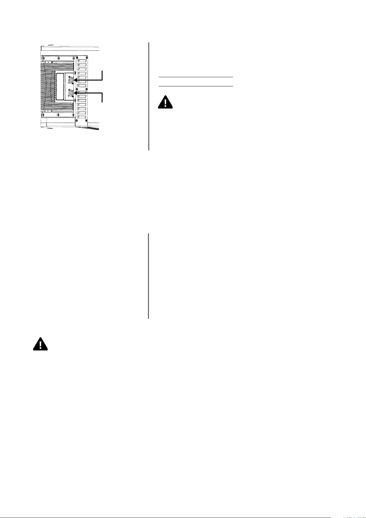
AC CABLES DAISY CHAINS
POWERCON IN
Each HDL 6-A/HDL12-AS module is provided with a Powercon outlet
to daisy chain other modules. The maximum number of modules that is
possible to daisy chain is:
230 VOLT: 6 modules total
115 VOLT: 3 modules total
POWERCON OUT
A superior number of modules in daisy chain will exceed the
Powercon connector maximum ratings and create a potentially
dangerous situation.
WARNING - RISK OF FIRE
POWERING FROM THREE PHASE
When the system is powered from a three phase power distribution it is very important to keep a good balance in the
load of each phase of the AC power. It is very important to include subwoofers and satellites in power distribution
calculation: both subwoofers and satellites shall be distributed between the three phases.
GENERAL RIGGING WARNINGS AND SAFETY PRECAUTIONS
RIGGING
• Suspending loads should be done with extreme caution.
THE SYSTEM
RCF has developed a complete procedure
to set up and hang an HDL 6-A line
array system starting from software data,
enclosures, rigging, accessories, cables,
until the final installation.
• When deploying a system always wear protective helmets and footwear.
• Never allow people to pass under the system during the installation
process.
• Never leave the system unattended during the installation process.
• Never install the system over areas of public access.
• Never attach other loads to the array system.
• Never climb the system during or after the installation.
• Never expose the system to extra loads created from the wind or snow.
WARNING
• The system must be rigged in accordance with the laws and regulations of the Country where the system is used. It is
responsibility of the owner or rigger to make sure that the system is properly rigged in accordance with Country and
local laws and regulations.
• Always check that all the parts of the rigging system that are not provided from RCF are:
-appropriate for the application
-approved, certified and marked
-properly rated
-in perfect condition
• Each cabinet support the full load of the part of the system below. It is very important that each single cabinet of the
system is properly checked.
Page 7
“RCF SHAPE DESIGNER” SOFTWARE AND SAFETY FACTOR
The suspension system is designed to have a proper safety factor (configuration dependent). Using the “HDL50
Shape Designer” software it is very easy to understand safety factors and limits for each specific configuration. To
better comprehend in which safety range the mechanics are working a simple introduction is needed: HDL 6-A arrays’
mechanics are built with certified UNI EN 10025 Steel. RCF prediction software calculates forces on every single
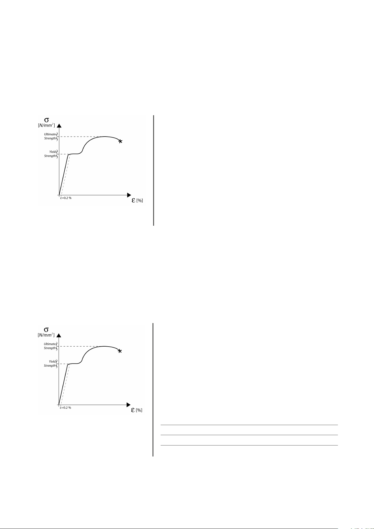
stressed part of the assembly and shows the minimum safety factor for every link. Structural steel has a stress-strain (or
equivalent Force-Deformation) curve as in the following:
The curve is characterized by two critical points: the Break Point and
the Yield Point. The tensile ultimate stress is simply the maximum stress
attained. Ultimate tensile stress is commonly used as a criterion of the
strength of the material for structural design, but it should be recognized
that other strength properties may often be more important. One of
these is certainly the Yield Strength. Stress-strain diagram of structural
steel exhibit a sharp break at a stress below the ultimate strength. At
this critical stress, the material elongates considerably with no apparent
change in stress. The stress at which this occurs is referred to as the Yield
Point. Permanent deformation may be detrimental, and the industry
adopted 0.2% plastic strain as an arbitrary limit that is considered
acceptable by all regulatory agencies. For tension and compression, the
corresponding stress at this offset strain is defined as the yield.
In our prediction software the Safety Factors are calculated considering the Maximum Stress Limit equal to the
Yield Strength, according with many international standards and rules.
The resulting Safety Factor is the minimum of all the calculated safety factors, for each link or pin.
This is where you are working with a SF=7
Depending on local safety regulations and on the situation, the
required safety factor can vary. It is responsibility of the owner or
rigger to make sure that the system is properly rigged in accordance
with Country and local laws and regulations.
The “RCF Shape Designer” software gives detailed information of the
safety factor for each specific configuration.
The results are classified in four classes:
-GREEN: SAFETY FACTOR > 7 SUGGESTED
-YELLOW 4 > SAFETY FACTOR > 7
-ORANGE 1.5 > SAFETY FACTOR > 4
-RED SAFETY FACTOR < 1.5 NEVER ADMITTED
Page 8
WARNING
• The safety factor is the result of the forces acting on fly bar’s and system’s front and rear links and pins and
depends on many variables:
- number of cabinets
- fly bar angles
- angles from cabinets to cabinets. If one of the cited variables change the safety factor MUST BE recalculated using the
software before rigging the system.
• In case the fly bar is picked up from 2 motors make sure that the fly bar angle is correct. An angle different from the
angle used in the prediction software can be potentially dangerous. Never allow persons to stay or pass under the
system during the installation process.
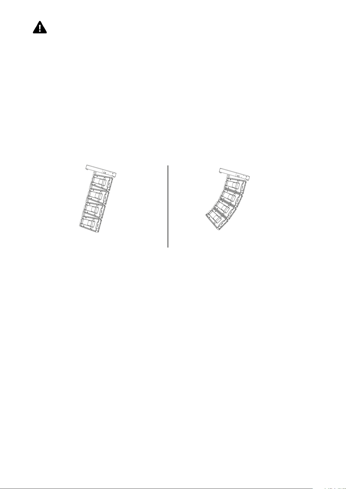
• When the fly bar is particularly tilted or the array is very curved the centre of gravity can move out from the rear links.
In this case the front links are in compression and the rear links are supporting the total weight of the system plus the
front compression. Always check very carefully with the “HDL 6-A Shape Designer” software all this kind of situations
(even with a small number of cabinets).
System particularly tilted System very curved
PREDICTION SOFTWARE – SHAPE DESIGNER
HDL 6-A Shape Designer is a temporary software, useful for the setup of the array, for mechanics and for proper preset
suggestions.
The optimal setting of a loudspeaker array cannot ignore the basics of acoustics and the awareness that many factors
contribute to a sonic result that matches expectations. RCF provides the user with simple instruments that help the
setting of the system in an easy and reliable way.
This software will soon be replaced by a more complete software for multiple arrays and complex venue simulation with
maps and graphs of the results.
RCF recommends this software to be used for each type of HDL 6-A configuration.
Page 9
SOFTWARE INSTALLATION
The software was developed with Matlab 2015b and requires Matlab programming libraries. At the very first installation
user should refer to the installation package, available from the RCF website, containing the Matlab Runtime (ver. 9) or
the installation package that will download the Runtime from the web. Once the libraries are correctly installed, for all
the following version of the software the user can directly download the application without the Runtime. Two versions,
32-bit and 64-bit, are available for the download.
IMPORTANT: Matlab no longer supports Windows XP and hence HDL50-ShapeDesigner (32 bit) doesn’t work with this
OS version.
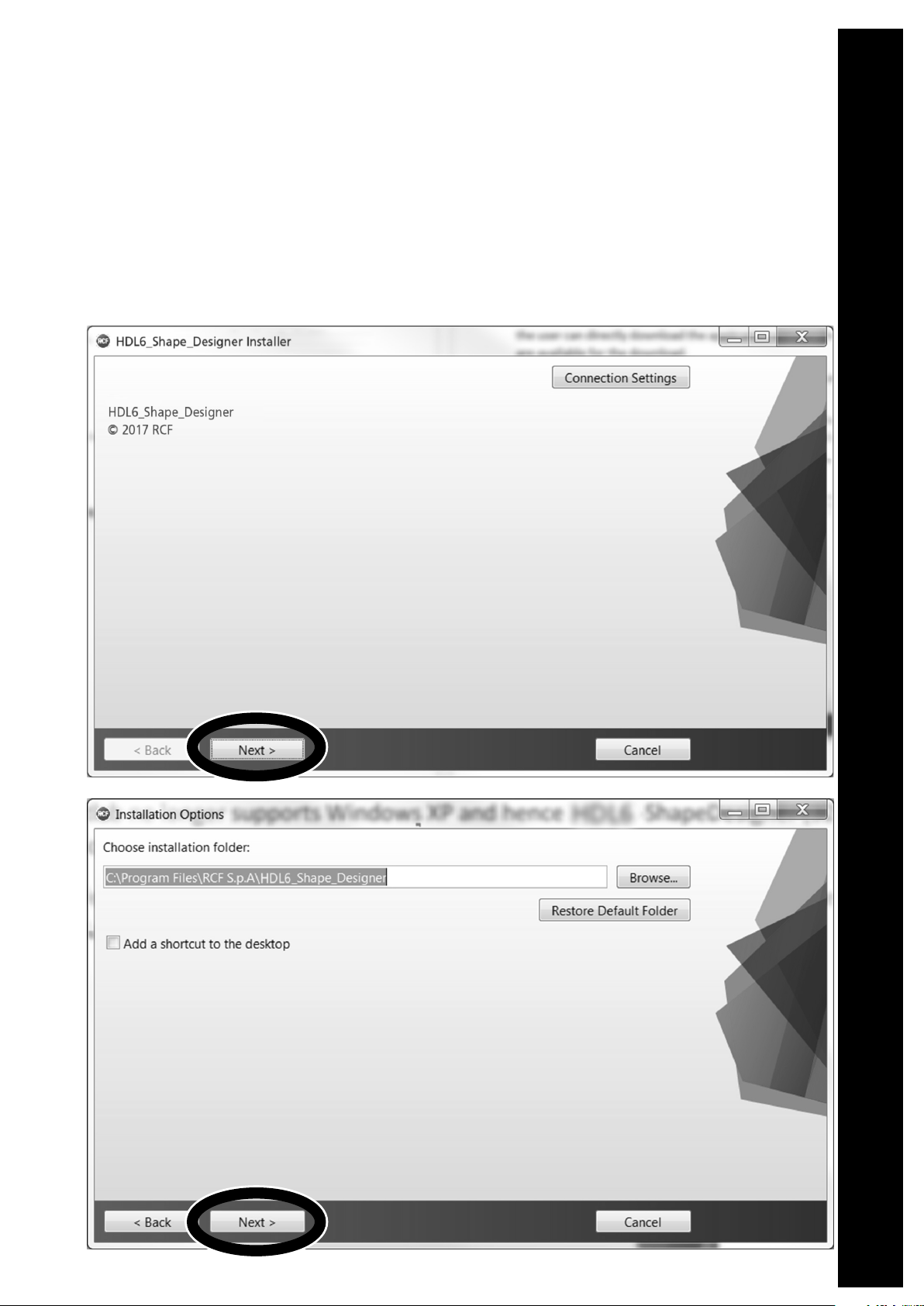
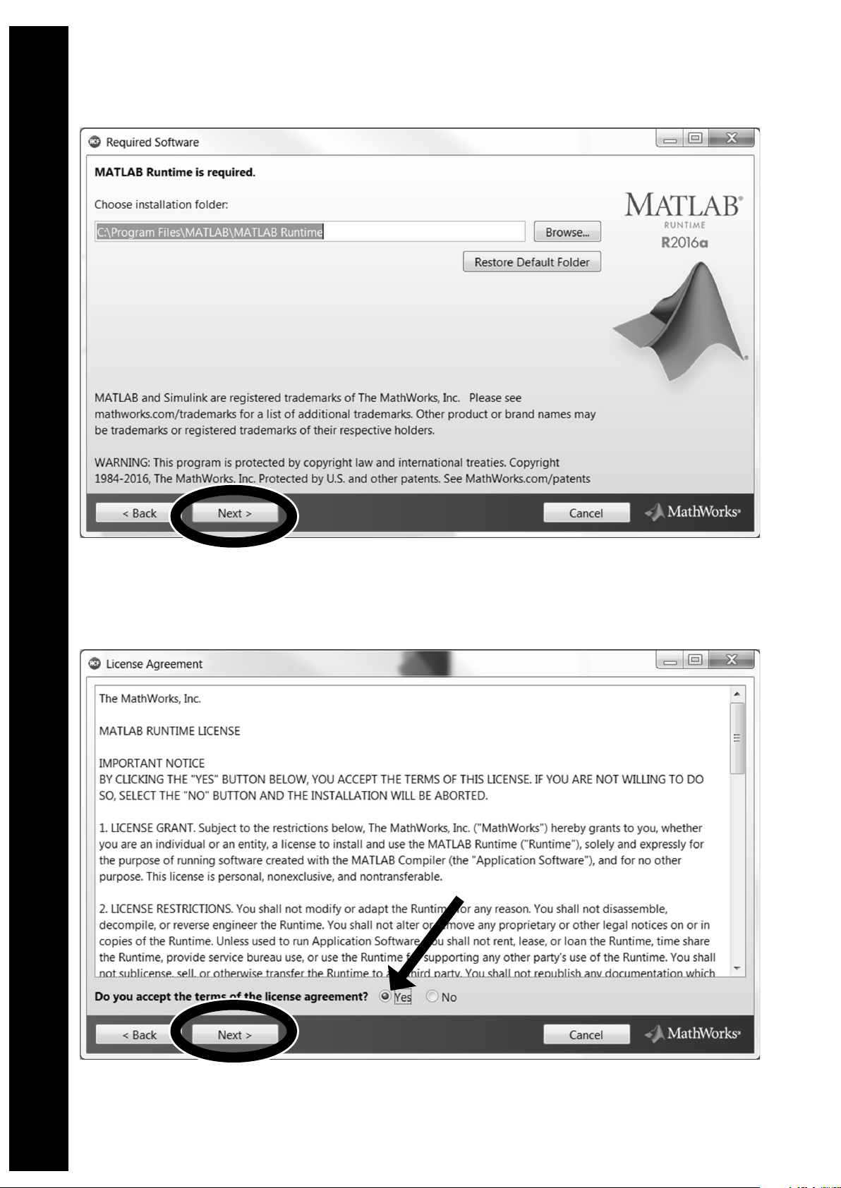
You may wait a few seconds after the double click on the installer because the software checks if Matlab Libraries are
available. After this step the installation begins. Double-click the last installer (check for the last release in the download
section of our website) and follow the next steps.
Page 10
Page 11
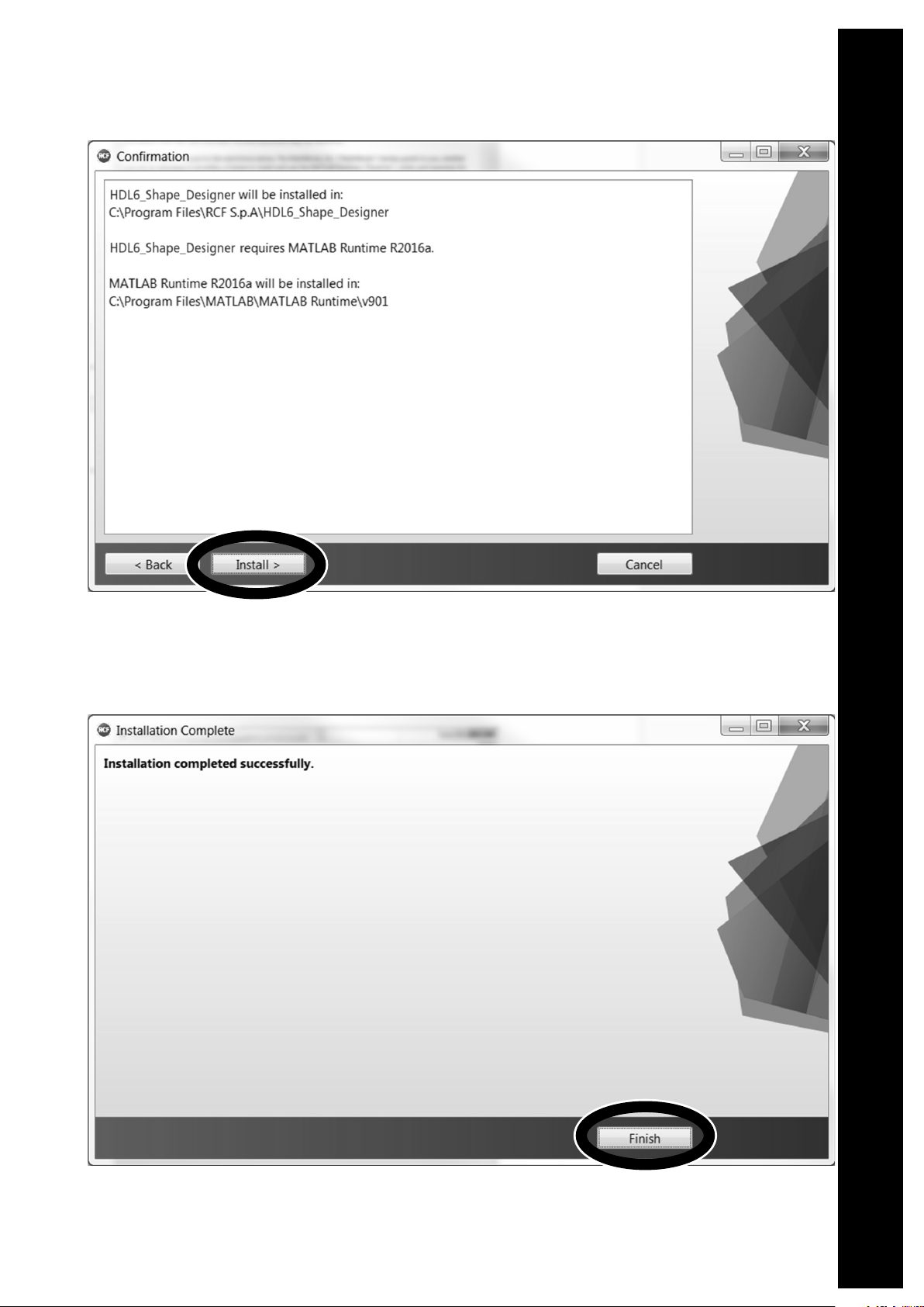
After the choice of folders for HDL6-SahpeDesigner software (Figure 2) and Matlab Libraries Runtime the installer takes
a couple of minutes for the installation procedure.
Page 12

DESIGN THE SYSTEM
The HDL6 Shape Designer software is divided into two macro sections: the left part of the interface is dedicated to
project variables and data (size of audiences to cover, height, number of modules, etc.), the right part shows the
processing results.
At first the user should introduce the audience data choosing the proper pop-up menu depending on the size of the
audience and introducing the geometrical data. It is also possible to define the height of the listener.
The second step is the array definition selecting the number of cabinets in the array, the hanging height, the number of
hanging points and the kind of available flybars. When selecting two hanging points consider those points positioned at
the flybar extremes.
The height of the array should be considered referred to the bottom side of the flybar, as shown in the picture below.
HEIGHT
After entering all the data input in the left part of the user interface, by pressing the AUTOSPLAY button the software will
perform:
- Hanging point for the shackle with A or B position indicated if a single pickup point is selected, rear and front load if
two pickup points are selected.
- Flybar tilt angle and cabinet splays (angles that we have to set to each cabinet before lifting operations).
- Inclination that each cabinet will take (in case of one pick up point) or will have to take if we were to tilt the cluster
with the use of two engines. (two pick up points).
- Total load and Safety Factor calculation: if the selected setup doesn’t give Safety Factor > 1.5 the text message shows
in red color the failure to meet the minimum conditions of mechanical safety.
Page 13

The autosplay algorithm was developed for optimum coverage of the audience size. The use of this function is
recommended for the optimization of the array aiming. A recursive algorithm chooses for every cabinet the best angle
available in the mechanics.
RECOMMENDED WORKFLOW
Pending the official and definitive simulation software, RCF recommends the use of HDL6 Shape Designer together with
Ease Focus 3. Because of the need of interaction between different software, the recommended workflow assumes the
following steps for every array in the final project:
- Shape Designer: audience and array setup. Calculation in “autosplay” mode of flybar tilt, cabinet and splays.
- Focus 3: reports here the angles, tilt of flybar and presets generated by Shape Designer.
- Shape Designer: manual modify of splay angles if the simulation in Focus 3 does not give satisfactory results in order to
check the safety factor.
- Focus 3: reports here the new angles and tilt of flybar generated by Shape Designer. Repeat the procedure until good
results are achieved.
Page 14

RIGGING COMPONENTS
Description Accessory p/n
1 BARRA SOSPENSIONE HDL6-A E HDL12-AS
- up to 16 HDL6-A
- up to 8 HDL12-AS
- up to 4 HDL12-AS + 8 HDL6-A
2 QUICK LOCK PIN 13360022
3 FLY BAR PICK UP HDL6-A 13360372
4 CONNECTION BRACKET FOR SECURELY LOCKING THE STACKING CLUSTER ON A SUBWOOFER
5 POLE MOUNT BRACKET
13360360
3
5
5
1
5
2
6
4
Page 15

1 13360129 HOIST SPACING CHAIN. It allows enough space for the hang of most 2 motor chain containers
and avoids any impact on the vertical balance of the array when it is suspended from a single
pick-up point.
2 13360372 FLY BAR PICK UP HDL6-A
+ 2 QUICK LOCK PIN (SPARE PART P/N 13360022)
3 13360351 AC 2X AZIMUT PLATE. It allows the horizontal aim control of the cluster. The system must be
hooked with 3 motors. 1 frontal and 2 attached to the azimuth plate.
4 13360366 KART WITH WHEELS AC KART HDL6
+ 2 QUICK LOCK PIN (SPARE PART 13360219)
5 13360371 AC TRUSS CLAMP HDL6
+ 1 QUICK LOCK PIN (SPARE PART P/N 13360022)
6 13360377 POLE MOUNT 3X HDL 6-A
+ 1 QUICK LOCK PIN (SPARE PART 13360219)
7 13360375 LINKBAR HDL12 TO HDL6
+ 2 QUICK LOCK PIN (SPARE PART 13360219)
8 13360381 RAIN COVER 06-01
1
3
5
500 mm
2
4
6
7
8
Page 16

RIGGING PROCEDURE
Installation and setup should only be carried out by qualified and authorized personnel observing the valid national Rules for
the Prevention of Accidents (RPA).
It is the responsibility of the person installing the assembly to ensure that the suspension/fixing points are suitable for the
intended use.
Always carry out a visual and functional inspection of the items before use. In the event of any doubt as to the proper
functioning and safety of the items, these must be withdrawn from use immediately.
WARNING - The steel wires between the locking pins of the cabinets and rigging components are not intended to carry any
load. The cabinet’s weight must only be carried by the Front and Splay/Rear links in conjunction with the front and rear rigging
strands of the loudspeaker cabinets and the Flying frame. Ensure all Locking pins are fully inserted and securely locked before
lifting any load.
In the first instance use HDL 6-A Shape Designer software to calculate the proper set up of the system and to check the safety
factor parameter.
The HDL6 flybar allows the suspension of HDL6-A and HDL12-AS.
Page 17

1. FLYBAR SETUP
S
The HDL6 flybar allows to set the central bar in two different configurations “A” e “B”.
Configuration “B” allows a better upper inclination of the cluster.
FLYBAR
WITH CENTRAL BAR
IN “A” POSITION
FLYBAR
WITH CENTRAL BAR
IN “B” POSITION
1.1 SET THE CENTRAL BAR IN “B” POSITION
X
S
R
This accessory is provided in “A” configuration.
To set it in “B” configuration:
1. Remove the cotter pins “R”, pull out the linchpins “X” and the
quick lock pins “S”
2. Lift the central bar then re-position it making the “B” indication
on the label and the holes “S” match together.
CENTRAL BRACKET LABEL
3. Re-assemble the flybar repositioning the pins “S”, the linchpins
“X” and the cotter pins “R”.
Page 18

PICK UP POINT
“A” POSITION
PICK UP POINT
“B” POSITION
PICK UP POINT
“A” POSITION
PICK UP POINT
“B” POSITION
1.2 PICK UP POINT POSITION
PICK UP POINT
“A” POSITION
PICK UP POINT
POSITION
2. SYSTEM SUSPENSION PROCEDURE
SINGLE PICK UP POINT
Position the flybar pick-up point as shown in the software, respecting the position “A” or “B”.
PICK UP POINT
“B” POSITION
DUAL PICK UP POINT
Allows to lift the cluster with two pulleys adding an optional pick up point (pn 13360372).
PICK UP POINT
“A” POSITION
PICK UP POINT
“B” POSITION
PICK UP POINT
“A” POSITION
PICK UP POINT
“B” POSITION
Page 19
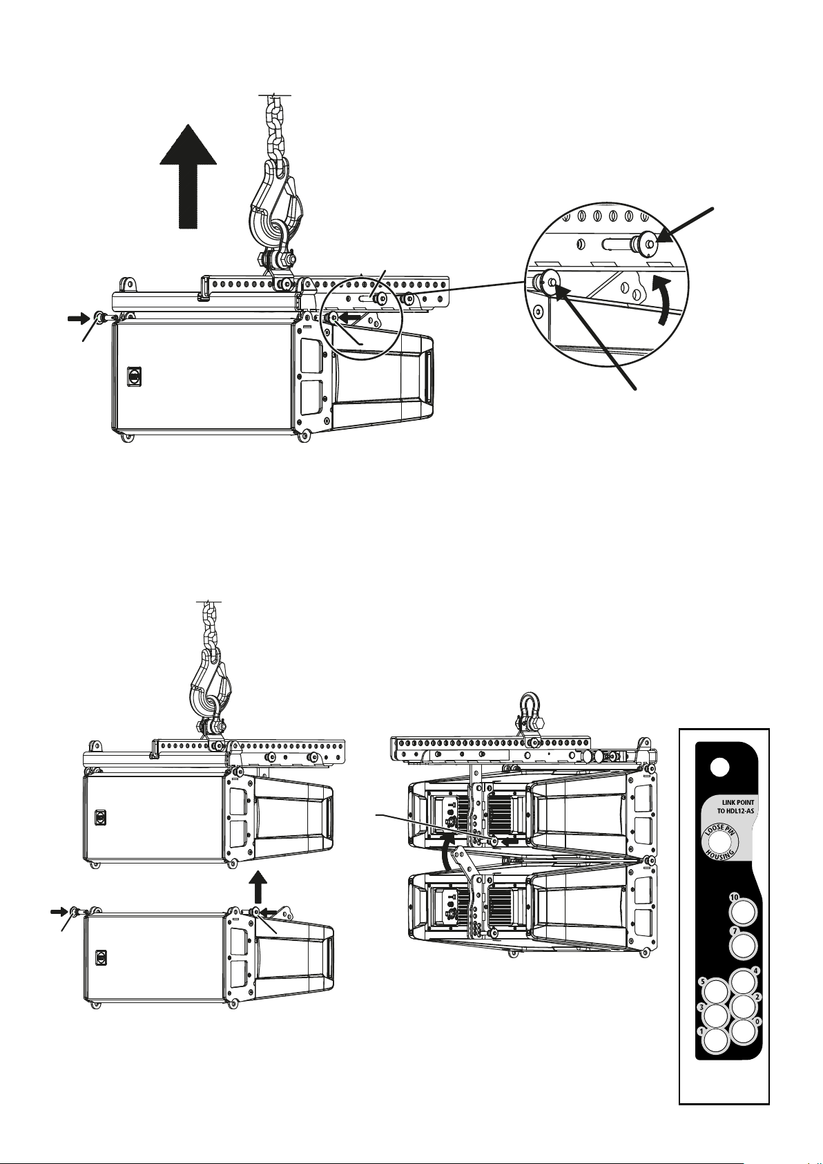
2.1 SECURING THE FLYBAR TO THE FIRST HDL6-A SPEAKER
S
F
F
S
F
P
F
S
S
S
F
1. Insert the frontal quick lock pins “F”
2. Rotate the rear bracket and secure it to the flybar with the rear quick lock pin “S” to the HDL6 Link Point hole
F
2.2 SECURING THE SECOND HDL6-A SPEAKER TO THE FIRST (AND CONSECUTIVE)
F
P
F
1. Secure the frontal quick lock pins “F”
2. Rotate the rear bracket and and secure it to the first speaker using the rear quick lock pin “P”, selecting the
inclination angle as shown on the software.
F
HDL6-A REAR
BRACKET LABEL
Page 20

2.3 SECURING THE FLYBAR TO THE FIRST HDL12-AS SPEAKER
S
F
1. Insert the frontal quick lock pins “F”
2. Rotate the rear bracket and secure it to the flybar with the rear quick lock pin “S” on the HDL12 Link Point hole.
F
2.4 SECURING THE SECOND HDL12-AS SPEAKER TO THE FIRST (AND CONSECUTIVE):
P
F
F
1. Pull out the frontal bracket “A”
2. Secure the frontal quick lock pins “F”
3. Rotate the rear bracket and secure it to the first speaker using the rear quick lock pin “P”.
Page 21

2.5 CLUSTER HDL12-AS + HDL6-A
1. Using the quick lock pin “P”, secure the linking bracket to the HDL6-A speaker on the “Link point to HDL12-AS” hole, on
the rear bracket.
2. Rotate the HDL6-A rear bracket and block it on the linking bracket between the two metal flaps.
P
F
F
1. Secure HDL6-A to HDL12-AS using the frontal quick lock pins “F” and the rear ones “P”.
WARNING: always secure both rear pins“P”.
Page 22

A
S
S
X X
B
S
A
S
S
X X
B
S
P
3. STACKING PROCEDURE
A
S
X X
B
S
Remove the central bar “A” from the flybar by pulling out the linchpins “X” and the quick lock pins “S”.
3.1 STACKING ON SUB HDL12-AS
S
1. Secure the flybar to HDL12-AS
2. Secure the stacking bar“B” (as shown in the picture) to the flybar using the quick lock pin “S” (follow the indication “stacking
point”)
P
F1
F1
1. Secure HDL6-A to the flybar using the frontal quick lock pins “F1”.
Page 23
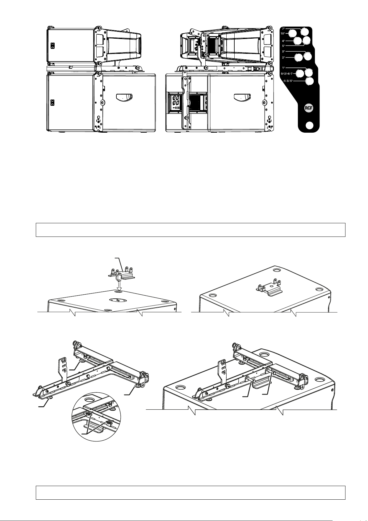
C
C
2. Select the inclination angle (positive angles indicate a lower inclination of the speaker) and secure it with the rear quick lock pin “P”.
To obtain the speaker inclination (positive or negative) you need to match the stacking bar angle value with the same angle
value stated on the speaker rear bracket.
This method works for every inclination except for angles 10 and 7 of the stacking bar, for which you need to proceed in the
following way:
- angle 10 of the stacking bar needs to be matched with angle 0 on the speaker rear bracket.
- angle 7 of the stacking bar needs to be matched with angle 5 on the speaker rear bracket.
WARNING: ALWAYS VERIFY THE SYSTEM SOLIDITY IN EVERY CONFIGURATION
3.1 STACKING ON DIFFERENT SUBWOOFERS (OTHER THAN HDL12-AS)
C
1. Screw the safety bracket “C” to the M20 insert on the subwoofer
P
P
X
X
P
R
1. Screw all three plastic feet “P”.
2. Secure the flybar to the safety bracket using the linchpins “X” and block them with the cotter pins “R”.
3. Adjust the feet to stabilize the flybar on the subwoofer then block them with thieir nuts to avoid unscrewing.
4. Assemble the HDL6-A speaker with the same procedure.
WARNING: ALWAYS VERIFY THE SYSTEM SOLIDITY IN EVERY CONFIGURATION
Page 24
3.2 GRAOUND STACKING
P
P
P
1. Screw all three plastic feet “P”.
2. Adjust the feet to stabilize the flybar on the subwoofer then block them with thieir nuts to avoid unscrewing.
3. Assemble the HDL6-A speaker with the same procedure.
WARNING: ALWAYS VERIFY THE SYSTEM SOLIDITY IN EVERY CONFIGURATION
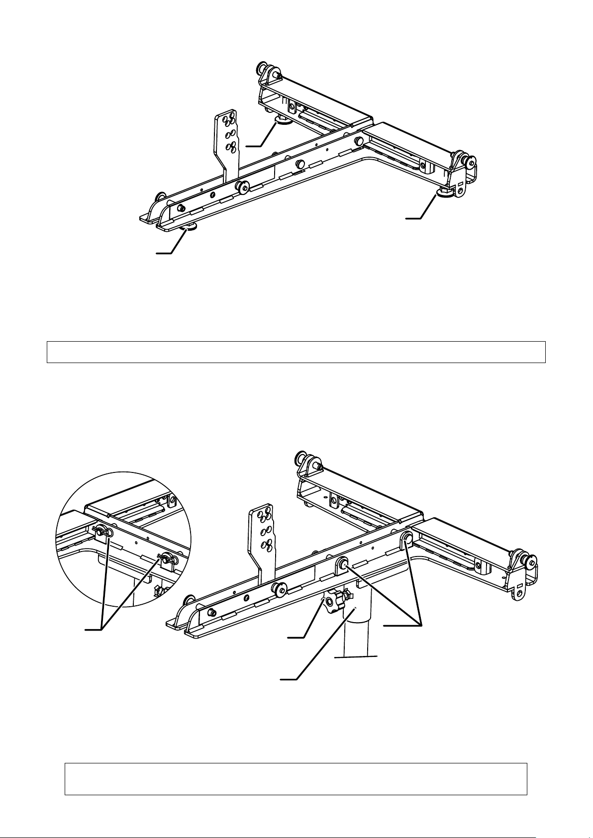
3.3 POLE MOUNTING WITH SUSPENSION BAR
R
M
X
D
1. Secure the pole mount bracket to the flybar with the linchpins “X” then block them with the cotter pins “R”
2. Block the flybar to the pole by screwing the knob “M”.
3. Assemble the HDL6-A speaker with the same procedure.
WARNING: ALWAYS VERIFY - THE SYSTEM SOLIDITY IN EVERY CONFIGURATION
- THE POLE PAYLOAD
Page 25

3.4 POLE MOUNTING WITH POLE MOUNT 3X HDL 6-A
D
M
X
1. Secure the flybar on the pole by screwing the knob “M”
2. Assemble the speakers HDL6-A with the same procedure
used on stacking on sub HDL12-AS
M
WARNING: ALWAYS VERIFY
- THE SYSTEM SOLIDITY IN EVERY CONFIGURATION
- THE POLE PAYLOAD
4. TRANSPORTATION:
POSITIONING THE SPEAKERS ON THE KART
F
F
1. Secure the front side of the speaker to the kart using the quick lock pins “F”
2. Secure the rear side of the speaker to the kart using the quick lock pins “P”.
Careful: the hole to be used is 0° on the speaker rear bracket.
3. Proceed with the second speaker repeating steps “1” and “2”
WARNING: the kart has been designed to carry up to 6 speakers.
P
Page 26

CARE AND MAINTENANCE – DISPOSAL
TRANSPORT – STORING
During transportation ensure the rigging components are not stressed or damaged by mechanical forces. Use suitable
transport cases. We recommend the use of the RCF HDL6-A touring kart for this purpose.
Due to their surface treatment the rigging components are temporarily protected against moisture. However, ensure the
components are in a dry state while stored or during transportation and use.
SAFETY GUIDE LINES – HDL6-A KART
Do not stack more than six HDL6-A on one Kart.
Exercise extreme caution when moving stacks of six cabinets with the Kart to avoid tipping.
Do not move stacks in the front-to-back direction of the HDL6-A’s (the long side); always move stacks sideways to avoid
tipping.
Page 27

SPECIFICATIONS
HDL 6-A HDL 12-AS
Frequency Response 65 Hz - 20 kHz 40 Hz - 120 kHz
Max Spl 131 dB 131 dB
Horizontal Coverage Angle 100° -
Vertical Coverage Angle 10° -
Compression Driver 1.0” neo, 1.7”v.c. -
Woofer 2 x 6.0” neo, 2.0”v.c. 12”, 3.0”v.c.
INPUTS
Input Connector XLR male Stereo XLR
Output Connector XLR female Stereo XLR
Input Sensitivity + 4 dBu - 2 dBu/+ 4 dBu
PROCESSOR
Crossover Frequency 900 Hz 80-110 Hz
Protections Thermal, RMS Thermal, RMS
Limiter Soft limiter Soft limiter
Controls HF correction Volume, EQ, phase, xover
AMPLIFIER
Total Power 1400 W Peak 1400 W Peak
High Frequencies 400 W Peak -
Low Frequencies 1000 W Peak -
Cooling convection convection
Connections Powercon in-out Powercon in-out
PHYSICAL SPECIFICATIONS
Height 237 mm (9.3”) 379 mm (14.9”)
Width 470 mm (18.7”) 470 mm (18.50”)
Depth 377 mm (15”) 508 mm (20”)
Weight 11.5 Kg (25.35 lbs) 24 Kg (52.9 lbs)
Cabinet Composite PP Baltic Birch Plywood
Hardware Integrated mechanics Array fittings, pole
Handles 2 rear 2 side
Page 28

www.rcf.it
RCF SpA: Via Raffaello, 13 - 42124 Reggio Emilia - Italy
tel. +39 0522 274411 - fax +39 0522 274484 - e-mail: rcfservice@rcf.it
10307557 RevD
 Loading...