

HIGH PERFORMANCE VERSATILE
COMPACT LIVE MIXERS
MIXER LIVE AD ALTE PRESTAZIONI
COMPATTO E VERSATILE
E12
OWNER MANUAL
MANUALE UTENTE

2
LANGUAGE
ENGLISH
ITALIANO312

3
IMPORTANT
WARNINGS
ENGLISH
SAFETY PRECAUTIONS
Before connecting and using this product, read the instructions provided in this manual carefully and keep it for future reference.
This manual is an integral part of the product and it must accompany it even in the case of changes of ownership, so that the new
owner is aware of the method of installation and use and all safety warnings. Incorrect installation and use of the product shall relieve
RCF S.p.A. of any and all liability.
CAUTION: to prevent the risk of flames or electric shock, do not ever expose this product to the rain or humidity.
1. All warnings, in particular those relating to safety, must be read with special attention, as they contain important information.
2. MAIN SUPPLY FROM THE MAINS
- The supply voltage of the device is sufficiently high to constitute a risk of electric shock to persons: never
install or connect the device with the power supply cable plugged into the mains.
- Before powering this product, make sure that all connections are correct and that the voltage of your mains
supply matches the value on the device data plate; if this is not the case, please contact an RCF dealer.
- The metal parts of the device are earthed via the power supply cable.
- A device with CLASS I construction must be connected to the mains socket with a protective earthing
connection.
- Make sure that the power supply cable of the device cannot be stepped on or crushed by objects, to make
sure it remains intact and in perfect working order.
- To avoid the risk of electric shock, never open the device: there are no parts that can be used by the user
inside.
3. Do not allow objects or liquids to penetrate the product, as this may cause a short circuit. The device must not be exposed to
dripping or splashing water; no naked flame sources (e.g. lighted candles) and no objects filled with liquid (e.g. vases) must be
placed on top of the device.
4. Do not perform any work / modifications / repairs except for those expressly described in this manual. Contact an authorised
service centre or highly qualified personnel when:
- the device is not working (or is working abnormally);
- the power supply cable has been seriously damaged;
- objects or liquids have penetrated the device;
- the device has undergone major knocks.
5. If this product is not used for long periods of time, unplug the power supply cable from the mains.
6. If the product releases abnormal odours or smoke, turn off the power immediately and unplug the power supply cable.
7. Do not connect this product to other devices and accessories not envisaged. Do not try to hang this product using elements
that are not designed or suitable for this purpose. To avoid the risk of falling, do not stack multiple units of this product, unless
this option is expressly specified in the instruction manual.
8. RCF S.p.A. strongly recommends that the installation of this product be carried out only by professional
qualified installers (or specialised installation companies) able to do it properly and to certify installation in
accordance with the applicable regulations in force. The entire audio system must comply with the applicable
rules and regulations regarding electrical systems.
9. Stands and Carts
Where envisaged, the product should only be used on carts or stands recommended by the manufacturer. The device-stand /
device-cart assembly should be moved with the utmost care. Sudden stops, excessive pushing force and uneven or tilted floors
could cause the assembly to overturn.
10. Hearing loss
Exposure to high sound levels can cause permanent hearing loss. The sound pressure level dangerous to one‘s hearing varies
greatly from one person to another and depends on the duration of exposure. To avoid potentially dangerous exposure to high
sound pressure levels, anyone who is exposed to these levels must use adequate protection; when a transducer capable of
producing high sound levels is in use, ear plugs or protective headsets must be worn. See the technical instruction data to find
out the maximum sound pressure levels that the speakers are capable of producing.
11. Place the product away from heat sources and ensure adequate air circulation all around.
12. Do not overload this product for extended periods of time.
13. Never force the controls (buttons, knobs, etc.).
14. Do not use solvents, alcohol, petrol or other volatile substances to clean the external parts of the unit; use a dry cloth.
15. Do not point microphones near and in front of the speakers, so as to avoid any feedback („Larsen effect“).
NOTE ON CABLES FOR AUDIO SIGNALS
To prevent the occurrence of noise on the cables that carry signals from the microphones or on the line (for example, 0dB), use only
screened cables and avoid laying them in the vicinity of:
- equipment that produces strong electromagnetic fields;
- cables from the power mains;
- speaker lines.
RCF S.p.A. thank you for buying this product, which was made in order to ensure reliability and high performance.

4
INFORMATION ON THE DEVICE
Thank you for purchasing a RCF mixing console.
E 12 is a versatile audio mixers equipped with all the tools needed for appropriately processing multiple audio signals from a variety of sources.
CLEAR SOUND
RCF mixing consoles devices combine RCF‘s professional “sound culture“ heritage with innovative design and dedicated manufacturing. RCF mixing
consoles secure clear sound, accurate sound dynamics and extreme versatility of use by passionate professional users. RCF mixing consoles are designed
to match perfectly with RCF active speakers.
RELIABILITY
All RCF mixing consoles undergo four extensive instrumental quality tests during construction. A listening test is carried out at the end of production
followed by a final quality control inspection to locate any appearance defects, such as scratches or dents. The process guarantees outstanding reliability
making sure that the device you have purchased is of the highest quality.
DESIGN
The unique design of RCF mixing consoles is an expression of typically Italian RCF creativity. RCF mixing consoles combine modern, excellent ergonomic
design. In addition to their striking appearance, the original side profile of the mixers makes them easy to grasp securely.
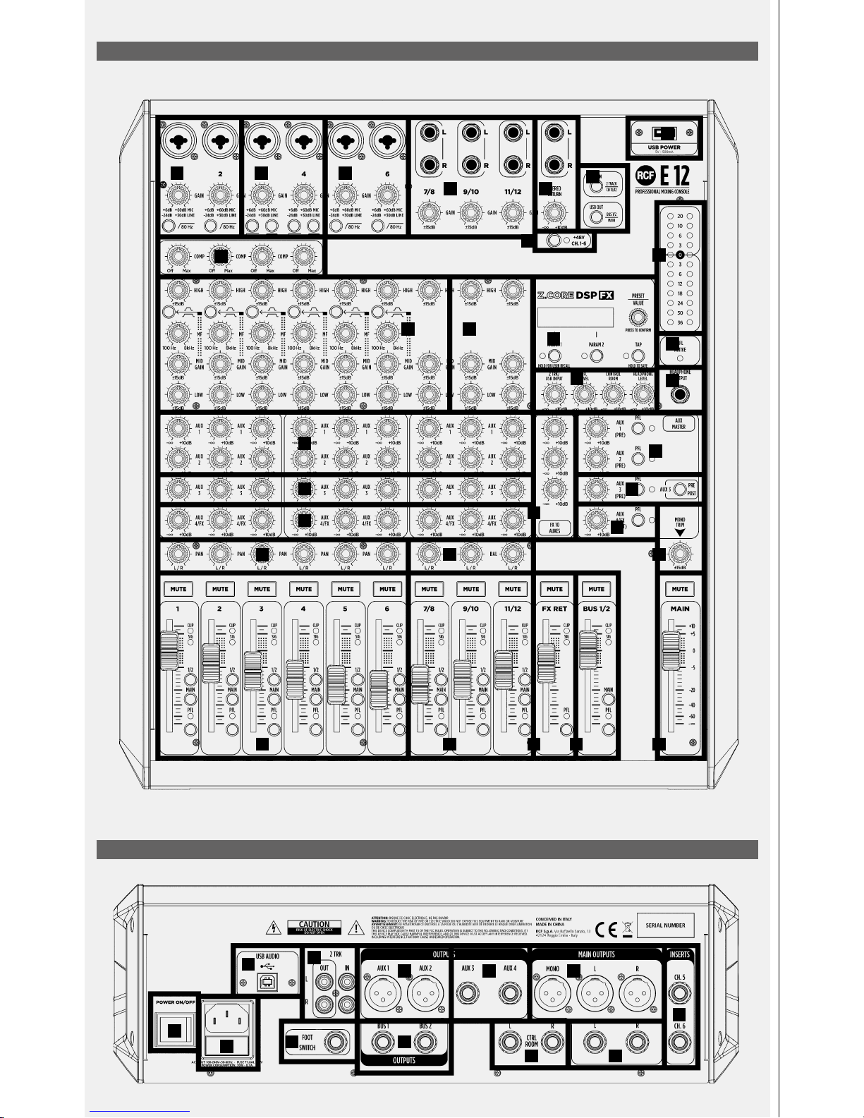
DESCRIPTION AND MAIN CHARACTERISTICS
E 12 is a versatile analogue audio mixers, equipped with a USB serial port for connection to a computer and all the tools required for proper processing of
multiple audio signals from different sources. At the internal of E 12 is present a Z.CORE DSP FX: the DSP unit offers 80 predefined presets: 40 reverbs, 20
delays and 20 modulation effects. 20 user presets are available and easily accessible.
E12 AUDIO INPUTS
- CHANNELS 1 to 6: Microphone or Line inputs (Combo connector), three-band EQ with semiparametric MID band with selectable Q width, INSERT serial
connection for external processors (¼“ jack) on Channels 5 & 6; signal compressor on the first 4 inputs.
- LINE INPUT 3 and 4 perform selectable HiZ (High Impedance) inputs.
- CHANNELS 7-8, 9-10 and 11-12: inputs for LINE level stereo signals (double ¼“ jack) with three-band equalizer; channels 11-12 are alternatively
assigned to the USB serial port.
- 1 STEREO RETURN stereo returns (double ¼“ jack).
- 2TK IN audio input (double RCA connector) for music source (e.g. CD player, MP3 player, etc..).
E12 AUDIO OUTPUTS
- MAIN MIX main stereo output with XLR male connectors (balanced) and ¼“ jack (unbalanced).
- MONO OUT with XLR male connector
- CONTROL ROOM stereo output (double ¼“ jack).
- 2 BUSSES OUT audio group outputs (¼“ jack).
- 4 AUX SEND auxiliary sends (2 male XLR and 2 ¼“ jack).
- 2TK OUT audio output for recorder.
- 1 FOOTSWITCH jack socket (¼“ TS jack) for foot control for the activation or deactivation of effects.
- USB port for connecting audio to and from your computer.
- 1 PHONES headphone outputs (¼” stereo jack)
Internal PSU 100 V-240 V, 50-60 Hz, 40 W
PHYSICAL SPECIFICATIONS
- Dimensions: L = 385 mm, W = 340 mm, H = 125mm
- Weight: 6,9 Kg
ENGLISH
5
FRONT PANEL / PANNELLO FRONTALE
REAR PANEL / PANNELLO POSTERIORE
30
31
32
33
34 35 36
37
38 39
40 41
1 12
3 4
5
6
7
8 9
10
11
13
14
15
16
17
18
19
20
20
21
22
23 24
25 26 27 28 29
12
6
ENGLISH
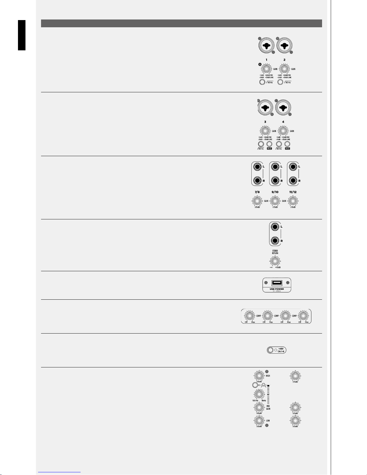
[1] MIC – LINE INPUTS
RCF E12 provides 6 mono Mic Line inputs via combo connectors. The Balanced XLR Microphone
preamp input supports sources with a gain range from +6dB to +60dB. The coaxial TRS jack supports
line signals with a gain of -24dB to +30dB. All the E12’s MIC-LINE inputs are supplied with a 80Hz
Hi-pass filter. Enable the 80Hz Hi-Pass filter when using microphone for voice to reduce low frequency
pop, bump and rumble noises. Connect your Microphones and your line sources here.
[2] INPUTS 3 & 4
Line inputs 3 & 4 add the selectable Hi-Z input feature. The Hi-Z input is very useful when connecting
low level musical instruments like Electric or Acoustic Guitars or Bass Guitars with passive pick-up.
[3] STEREO INPUTS
TRS jacks 7/8, 9/10 and 11/12 provide Stereo inputs for line sources with +/- 15 dB gain
[4] STEREO RETURN INPUTS
TRS Jacks provide a further stereo line input with level control from -∞ to +10dB. Ideal when using an
external effects unit to send the effect signal back to the mixer. STEREO RETURN is the ideal connection
for stereo sources like background music players.
[5] USB POWER
This Type A USB port provides a power of 5V – 500mA ideal for power up of a USB lamp or fan or to
recharge any USB mobile devices.
[6] COMPRESSORS
Input channels 1 to 4 are provided with intuitive and powerful single control dynamic compressors.
With thresholds and ratio parameters properly designed the E12 compressors allow even the most
dynamically demanding signals to be controlled.
[7] +48V SWITCHES
Dedicated to the Mic input this switch allow enabling of the +48V Phantom Power to the Mic input: 1-6.
Enabling of the Phantom power is necessary only in presence of Condenser and Electret Microphones
or in case of use of D.I. boxes.
[8] EQ
All the E12’s mono channels are provided with a sophisticated and precise 3-band parametric EQ.
Low frequency control sets in at 100Hz with a gain of +/-15dB and shelving curve. Hi frequency
control sets in at 10kHz with a gain of +/-15dB and shelving curve. Mid frequency control works in
a selectable frequency range between 100 Hz and 8 kHz with a gain of +/-15dB. Mid band feature
a switch for the selection of the band “Q”. The selection is between WIDE or NARROW “Q” action.
[9] Stereo channels are provided with a 3-band EQ
FRONT PANEL FUNCTIONS

7
ENGLISH
[10] Z.CORE DSP FX PANEL
The Z.CORE DSP FX is the effects unit present inside the RCF E Series mixers,featuring a high-quality 32-bit floating-point DSP engine, running at a
sample rate of 48 kHz.
Z.CORE DSP FX include 80 different ROM effects programs divided as follow:
P001-P040: REVERBS including: HALL, ROOM, PLATE, AMBIENCE algorithms (up to 11 s decay time)
P041-P060: DELAYS including: STEREO, VINTAGE, MODERN, ER, DUAL algorithms (up to 1 s delay)
P061-P080: MODULATION EFFECTS including: CHORUS, FLANGER, TREMOLO algorithms
The memory locations included between:
U01-U20 (USER1 to USER20) are available for storing user edited programs, becoming ready for a quick recall.
To navigate the Z.CORE DSP FX unit a two-line display is present: the upper line shows the Preset Name, while the lower line indicates the Preset
Number and algorithm type.
To select a program or user memory, rotate the encoder (orange) called PRESET/VALUE; then, press the encoder to recall the selected program.
Three buttons are present below the display:
- PARAM1 / HOLD FOR USER RECALL
- PARAM2
- TAP / HOLD TO SAVE
Pressing the PARAM1 button enables the edit of the first parameter:
- DECAY when Reverb Algorithms are in use
- TIME when Delay Algorithms are in use
- RATE when Modulation Algorithms (chorus, flanger, tremolo) are in use.
Rotate the encoder to change this value.
Pressing the PARAM2 button enables the edit of the second parameter:
- DAMPING when Reverb Algorithms are in use
- FEEDBACK when Delay Algorithms are in use
- DEPTH when Modulation Algorithms (chorus, flanger, tremolo) are in use.
Again, rotate the encoder to change this value.
By holding down the PARAM1 button for more than 3 seconds (HOLD FOR USER RECALL) it’s possible to have direct access to the USER Library (U01
U20). Rotate the PRESET/VALUE encoder to navigate and press it to confirm the selection, and quickly recall a previously saved USER Preset.
The button TAP/HOLD TO SAVE has a double function. When the current effect is a Delay, the button synchronizes the delay time to the current music.
Holding down this button it’s possible to save the current effect program to one of the 20 USER PRESETS.
Hold down the TAP/HOLD TO SAVE button for more than 3 seconds, and on the display will appear the question: Save to USER1? Rotating the
ENCODER change the number of USER from 1 to 20; select an available USER preset and press the encoder to confirm. Now on the display the
default name of the chosen USER preset will appear. The display shows: ENTER NAME to be written. Rotate the ENCODER to select the preferred
letter, number or symbol. You can move the cursor left or right using the PARAM1 and PARAM2 buttons, and when the name of your USER preset is
complete, press the encoder to confirm. The stored preset will appear on the display.
The preset currently in use, either USER or ROM, will be recalled automatically at power-up.
When the effect send is muted via footswitch (see sect. 38 of rear panel description) the red LED close to the TAP/HOLD TO SAVE button turns on, and
the display shows the message “FX MUTE“indicating the FX is muted externally.
In this condition, the effect can be unmuted by pressing the TAP/HOLD TO SAVE button once. When the effect is unmuted, the red LED and the button
return to their normal function.
[11] LEVEL METER
This 12 LED elements level meter normally allows you to control the Main Mix output level. When a channel PFL button is
pressed, the level meter shows the PFL level present in the selected channel. Keep the input level below the “0” indication to
avoid overloaded signals that can cause distortion.
[12] USB OUT – USB IN BUTTONS
These two buttons determine where the USB audio paths are routed to/from. USB OUT – select which stereo audio channels
are destined to a computer for recording: when the button is in up position the audio signals present in MAIN MIX are assigned
to the USB port of a computer; when the button is in down position (pressed) BUSSES 1/2 audio channels are routed to the
USB port.
USB IN determines where to route the stereo audio channels played from an external computer connected to the USB port:
when the button is in upper position (not pressed) the audio is routed to 2TRACK IN audio path and its level is controlled by the
2TRACK/USB Grey Knob (see section 13): If the USB IN button is pressed the audio coming from an external computer is routed
to the stereo channel 11/12; in this case the USB audio substitutes the analog audio input (see section 3) and takes advantage
of all the features provided by the stereo channel such as EQs, AUX sends, BAL and fader control.
FRONT PANEL / PANNELLO FRONTALE

8
ENGLISH
FRONT PANEL FUNCTIONS
[13] MONITOR SECTION
In this panel four knobs are present; PFL LEVEL controls the level of PFL bus. The PFL signal can be
listened through CONTROL ROOM when two speakers are connected to CTRL ROOM OUTPUT jacks
(see section 11 on Back Panel description) or through HEADPHONE OUTPUT (see section 15). Both
CONTROL ROOM and HEADPHONE OUTPUT are provided with individual level control. CONTROL
ROOM level knob: level control of the signal routed to CTRL ROOM OUTPUT. During the normal use
of the mixer the MAIN MIX signal is routed to this output; when one or more PFL buttons are pressed
the PFL bus signal will be routed to CTRL ROOM OUTPUT and HEADPHONES OUTPUT. HEADPHONES
LEVEL controls the level of the signal sent to the HEADPHONES OUTPUT; set this control to minimum
(-∞) before connection and wear headphones to avoid hearing loss. 2TRACK/USB INPUT controls the
level of the signal present on the 2TRK IN RCA connector (see section 4 of Back Panel description)
and the signal coming from a computer connected to the USB port (see section 32 of the Back Panel
description).
[14] CUE ACTIVE LED
This led lights up when one or more PFL buttons are pressed
[15] HEADPHONES OUTPUT
Connect headphones here to listen to MAIN MIX or PFL signals
[16] AUX SENDS 1 AND 2
Each channel of the E16 mixer is provided with 4 auxiliary sends; the AUX SENDS 1 and 2 are pre fader
sends. The signal of AUXES 1 and 2 are routed to the AUX1 and AUX2 OUTPUTS XLR present on the
back panel (see section 34 on Back Panel description).
[17] AUX SENDS 3
AUX 3 is a selectable pre-fader/post-fader auxiliary send; it is possible to select the pre/post position
pressing the pre/post button (see section 21) positioned close to the AUX 3 MASTER potentiometer
(see section 20). When the selection is pre-fader AUX 3 takes the signal from the channel independently
from the fader position; when the selection is post-fader the AUX 3 takes the signal subjected to the
fader position.
[18] AUX SENDS 4/FX
AUX SEND 4 is a post-fader auxiliary send. This aux feeds the internal Z.CORE DSP FX but in some cases
can be used as further auxiliary send for monitor purpose.
[19] FX TO AUX
These sends allow routing of the signal present in the FX return channel to the AUX sends.
[20] AUX MASTER SECTION
These potentiometers control the general level of the single AUX SENDS from 1 to 3. The PFL button
when pressed allows listening to the signal present in the single aux sends, through speakers connected
to the CTRL ROOM OUTPUT (see section 40 of the back panel description) or through headphones
connected to HEADPHONES OUTPUT (see section 15).
[21] AUX 3 PRE/POST BUTTON
This button allows selection of the AUX 3 position, pre-fader or post-fader; (see section 17)
[22] PAN
These controls allow positioning of the signal present in the mono channel in the stereo image of the
stereo MAIN MIX or BUS OUT.
[23] BAL
These controls characteristic of stereo channels allow balancing of the position of a stereo channel into
the stereo image of the stereo MAIN MIX or BUS OUT.

9
ENGLISH
FRONT PANEL FUNCTIONS
[24] MONO TRIM
The MONO TRIM control allows balancing of the level of MONO OUT with a range of + or - 15dBs.
[25] MONO CHANNELS FADERS SECTION
This section allows control of the level of the 6 mono input channels and their routing to the output.
Each one of the faders has several control buttons:
MUTE: the MUTE button when pressed inhibits the signal to flow to the output bus or main mix paths.
1/2 and MAIN buttons positioned on the right side of each fader allow the signal to be routed
respectively to STEREO BUS 1/2 or MAIN MIX.
The PFL button allows listening to the signal present on the channel through speakers connected to the
CTRL ROOM OUTPUT (see section 40 of the back panel description) or through headphones connected
to HEADPHONES OUTPUT (see section 15).
[26] STEREO CHANNELS FADERS SECTION
Same function as the MONO CHANNELS FADERS section applied to stereo channels.
[27] FX RET FADER
This fader controls the level of the signal coming from the internal Z.CORE DSP FX. The MUTE
button when pressed inhibits the signal flow to the main mix path. The PFL button when pressed
allows listening to the signal present in FX return channel through speakers connected to the CTRL
ROOM OUTPUT (see section 40 of the back panel description) or through headphones connected to
HEADPHONES OUTPUT (see section 15).
[28] BUS FADER
The faders BUS 1/2 controls the level of this stereo bus out. BUS 1/2 can be fed with each one of the
input channels to create a stereo audio group routed to the physical output BUS1 – BUS2 (see section
39 on back panel description). The MUTE button when pressed inhibits the signal flow to the BUS
output or main mix paths. The MAIN button positioned close the BUS fader routes the BUS to the MAIN
MIX. The PFL button when pressed allows listening to the signal present into BUS through speakers
connected to the CTRL ROOM OUTPUT (see section 40 of the back panel description) or through
headphones connected to HEADPHONES OUTPUT (see section 15).
[29] MAIN FADER
The MAIN fader controls the level of the MAIN MIX and the MONO signal (refer to the section 36 of
the back panel description).
 Loading...