

Page 1

USER MANUAL
MANUALE D’USO
RP 9600
- DXT 9000 – EVACUATION /
PAGING AUDIO SYSTEM
- RP 9600 – DATA REPEATER
- DXT 9000 – SISTEMA
AUDIO PER ANNUNCI ED
EMERGENZE
- RP 9600 – RIPETITORE DATI
Page 2

Page 3

TABLE OF CONTENTS
INDICE
ENGLISH
SAFETY PRECAUTIONS
DESCRIPTION
19” RACK INSTALLATION
FRONT PANEL
REAR PANEL
MAIN MENU
SPECIFICATIONS
ITALIANO
AVVERTENZE PER LA SICUREZZA
DESCRIZIONE
INSTALLAZIONE NEI RACK DA 19”
PANNELLO FRONTALE
PANNELLO POSTERIORE
MENÙ PRINCIPALE
DATI TECNICI
4
6
7
7
9
9
12
14
16
17
17
19
19
22
Page 4
4
ENGLISH
IMPORTANT
WARNING
SAFETY PRECAUTIONS
IMPORTANT
Before connecting and using this product, please read this instruction manual carefully and keep it
on hand for future reference.
The manual is to be considered an integral part of this product and must accompany it when it
changes ownership as a reference for correct installation and use as well as for the safety precautions.
RCF S.p.A. will not assume any responsibility for the incorrect installation and / or use of this product.
WARNING: To prevent the risk of re or electric shock, never expose this product to rain or humidity.
This device is intended for indoor use only.
SAFETY PRECAUTIONS
1. All the precautions, in particular the safety ones, must be read with special attention, as they
provide important information.
2.1 PRIMARY POWER SUPPLY FROM MAINS
- The mains voltage is sufciently high to involve a risk of electrocution: never install or connect this
product when its power cord is plugged in.
- Before powering up, make sure that all the connections have been made correctly and the voltage
of your mains corresponds to the voltage shown on the rating plate on the unit, if not, please
contact your RCF dealer.
- This apparatus can be connected to either TT or TN earthing arrangements only.
- The metallic parts of the unit are earthed by means of the power cord. An apparatus with CLASS
I construction shall be connected to a mains socket outlet with a protective earthing connection.
- This apparatus shall be connected to a facility equipped device to protect against earth faults,
appropriately sized for the type and power of the installed line (RCD).
- Protect the power cord from damage. Make sure it is positioned in a way that it cannot be stepped
on or crushed by objects.
- To prevent the risk of electric shock, never open this product: there are no parts inside that the
user needs to access.
- The mains plug is used to disconnect the device and it shall remain readily operable.
2.2 SECONDARY (/ EMERGENCY) POWER SUPPLY THROUGH BATTERIES
- The apparatus operating voltage is 48 V dc (therefore, it is necessary to connect in series several
batteries having a lower nominal voltage, example: 4 x 12 V, 2 x 24 V).
- Always use rechargeable batteries, which need to be chosen according to the maximum possible
load.
- Verify the polarity of batteries is correct.
- Do NOT short-circuit batteries (i.e. connecting the 2 opposite poles together with metallic wires).
- The 48 V dc plug is used to disconnect the device and it shall remain readily operable.
- The 48 V dc power supply does not go beyond the fact that there are dangerous voltages inside
the unit.
- Throw empty batteries away according to your country laws about ecology and environment
protection.
3. Make sure that no objects or liquids can get into this product, as this may cause a short circuit.
This apparatus shall not be exposed to dripping or splashing. No objects lled with liquid (such as
vases) and no naked sources (such as lighted candles) shall be placed on this apparatus.
4. Never attempt to carry out any operations, modications or repairs that are not expressly described
in this manual.
Contact your authorized service centre or qualied personnel should any of the following occur:
- The product does not function (or functions in an anomalous way).
- The power cord has been damaged.
- Objects or liquids have got into the product.
- The product has been subject to a heavy impact.
5. If this product is not used for a long period, disconnect its power cord and batteries.
6. If this product begins emitting any strange odours or smoke, switch it off immediately and
disconnect its power cord and batteries.
Page 5
5
ENGLISH
7. The terminals marked with the symbol are HAZARDOUS LIVE and their connection is to be
made by an INSTRUCTED PERSON or the use of ready-made cables is required.
8. Do not connect this product to any equipment or accessories not foreseen.
For suspended installation, only use the dedicated anchoring points and do not try to hang this
product by using elements that are unsuitable or not specic for this purpose.
Also check the suitability of the support surface to which the product is anchored (wall, ceiling,
structure, etc.), and the components used for attachment (screw anchors, screws, brackets not
supplied by RCF etc.), which must guarantee the security of the system / installation over time, also
considering, for example, the mechanical vibrations normally generated by transducers.
To prevent the risk of falling equipment, do not stack multiple units of this product unless this
possibility is specied in this user manual.
9. RCF S.p.A. strongly recommends this product is only installed by professional
qualied installers (or specialised rms) who can ensure correct installation and certify
it according to the regulations in force.
The entire audio system must comply with the current standards and regulations
regarding electrical systems.
10. SUPPORTS AND TROLLEYS
The equipment should be only used on trolleys or supports, where necessary, that are recommended
by the manufacturer. The equipment / support / trolley assembly must be moved with extreme caution.
Sudden stops, excessive pushing force and uneven oors may cause the assembly to overturn.
11. Mechanical and electrical factors need to be considered when installing a professional audio
system (in addition to those which are strictly acoustic, such as sound pressure, angles of coverage,
frequency response, etc.).
12. HEARING LOSS
Exposure to high sound levels can cause permanent hearing loss. The acoustic pressure level that
leads to hearing loss is different from person to person and depends on the duration of exposure. To
prevent potentially dangerous exposure to high levels of acoustic pressure, anyone who is exposed
to these levels should use adequate protection devices.
When a transducer capable of producing high sound levels is being used, it is therefore necessary to
wear ear plugs or protective earphones.
See the technical specications in loudspeaker instruction manuals to know their maximum sound
pressure levels.
13. Do not obstruct the ventilation grilles of the unit. Situate this product far from any heat sources
and always ensure adequate air circulation around the ventilation grilles.
14. Never force the control elements (keys, knobs, etc. ).
15. Do not use solvents, alcohol, benzene or other volatile substances for cleaning the external parts
of this product.
Use a dry cloth.
WARNING:
Any change made by unauthorized
personnel to the product and / or the
system (in which it is installed and
congured, including rack cabinet and
wiring) may invalidate the CE marking
(certication EN54-16: 2008) and also
the product warranty.
Page 6
6
ENGLISH
RCF S.P.A. THANKS YOU FOR PURCHASING THIS PRODUCT, WHICH HAS BEEN
MADE TO GUARANTEE RELIABILITY AND HIGH PERFORMANCE.
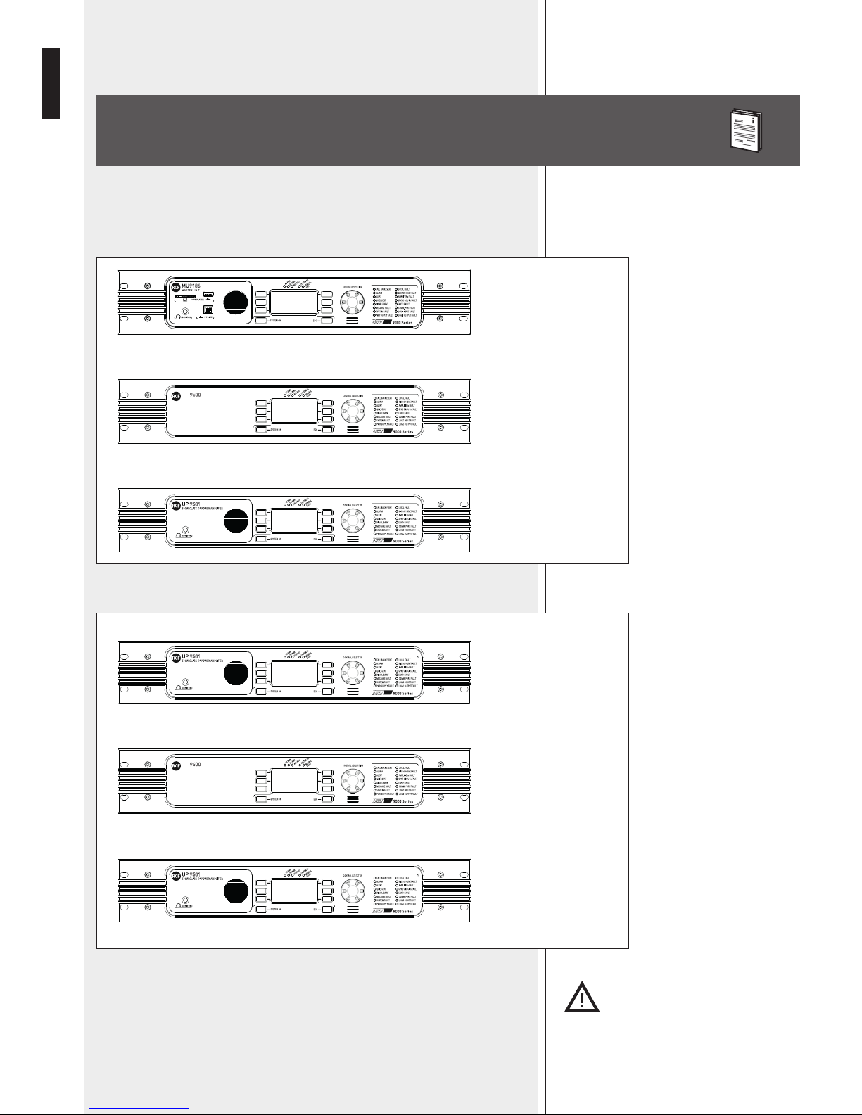
RP 9600 ‘Data Repeater’ is a DXT 9000 system component that needs to be inserted
between the master unit (either MU 9186 or MU 9186/R or MX 9502 or MX 9504) and
ampliers (UP 9501 / UP 9502 / UP 9504) when the bus cable is longer than 180 metres
or the system includes more than 15 UP 950x ampliers.
It is also possible to insert a RP 9600 data repeater between an amplier and the next one.
DESCRIPTION
RP
DATA REPEATER
RP
DATA REPEATER
BUS OUT
BUS IN
BUS OUT
BUS IN
MU 9186
(MX 9502 / 9504)
RP 9600
UP 9501 / 9502 /
9504
RP
DATA REPEATER
RP
DATA REPEATER
BUS OUT
BUS IN
BUS OUT
BUS IN
RP 9600
UP 9501 / 9502 / 9504
UP 9501 / 9502 / 9504
NOTE:
RP 9600 daTa REPEaTERs shall bE PlacEd iN aREas accEssiblE TO auThORizEd PERsONNEl ONly.
Refer to the master unit user manual (MU 9186 or MX 9502 / 9504) about DXT 9000
system description.
Page 7
7
ENGLISH
19” RACK INSTALLATION
Fix the RP 9600 data repeater to the front side of a 19” rack cabinet through 4 screws.
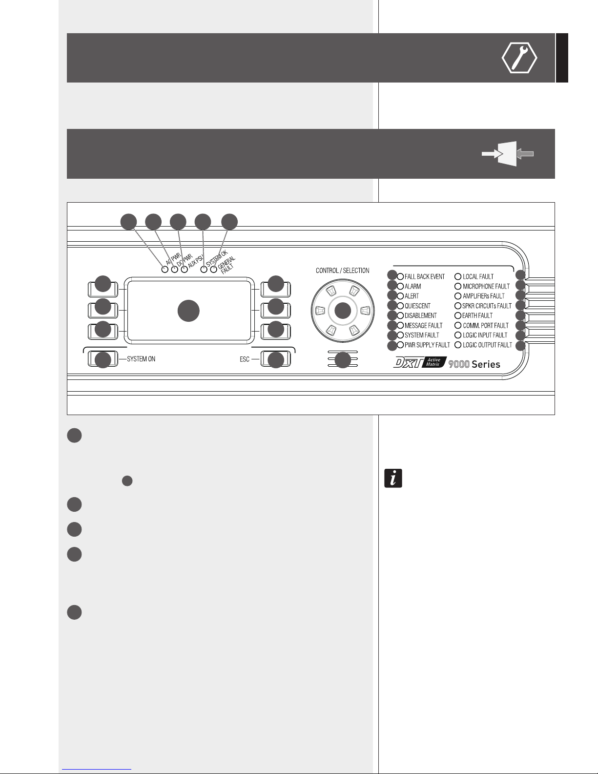
FRONT PANEL
1 2
11
13
16
12
15
14
17
18
19
21
24
20
23
22
25
26
5
4
3 3
3 3
3 3
7 8 9 106
27
1
SYSTEM ON button: press and hold to turn the RP 9600 data repeater on (when off).
The
SYSTEM ON
buTTon does noT Turn The main uniT off. To swiTch The main uniT off, make sure
The 48 V dc power supply (baTTeries) is noT presenT and use eiTher The proper sofTware funcTion or
The main power
32 swiTch on The rear panel.
2
ESC (‘Escape’) button: press to quit the displayed menu.
3
Six buttons to select the respective functions shown on the display.
4
CONTROL / SELECTION: rotary encoder and push-button to select.
Turn the control clockwise to scroll the display or either increase or decrease the selected
parameter value.
Press to select.
5
Display LCD
Page 8
8
ENGLISH
6
÷ 26 LEDs
27
Internal buzzer for fault alert (or evacuation message in progress).
It can be muted by pressing the SYSTEM ON
1
button.
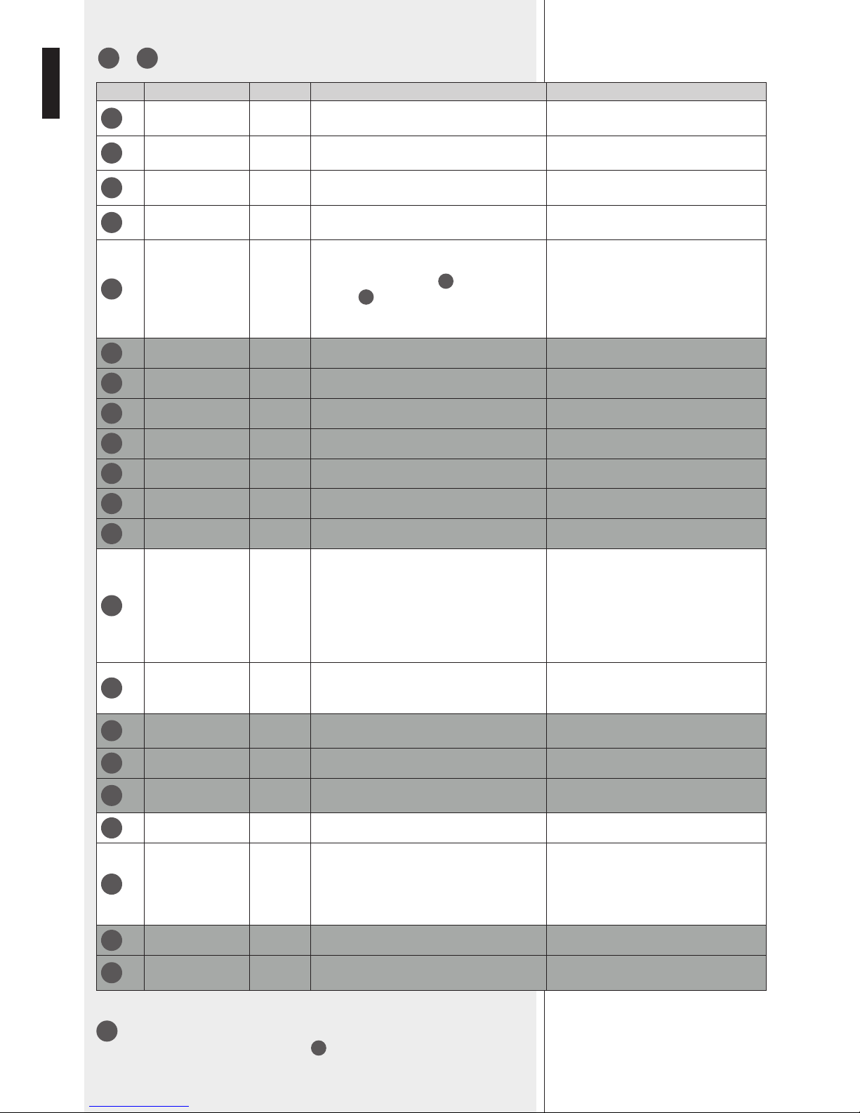
No. SILK SCREEN COLOUR INDICATION (WHEN LIT) FURTHER INFORMATION
6
AC PWR Green
The mains power (AC) is present and the
respective fuse is intact.
If the LED is off, the mains power is not
available (or out of range).
7
DC PWR Green
48 V dc power supply is present and the
respective fuse is intact.
If the LED is off, 48 V dc is not available (or
out of range).
8
AUX PSU Green
The data repeater is turned on and its stand-by
power supply unit operates properly.
9
SYSTEM OK Green
No detected faults:
the entire system is operating properly.
The LED is lit when no faults are detected
on any system device.
10
GENERAL FAULT Yellow
One or more faults have been detected,
including problems on power supply, so it can
be lit even if the AC PWR
6
and
DC PWR 7 green LEDs are off.
The LED gets lit even in case of failure of any
peripheral unit.
If a system logic input (GPI) is set to obtain
a fault remote indication of an external
device, a possible problem is indicated by
the GENERAL FAULT LED.
11
FALL BACK EVENT LED disabled.
12
ALARM LED disabled.
13
ALERT LED disabled.
14
QUIESCENT LED disabled.
15
DISABLEMENT LED disabled.
16
MESSAGE FAULT LED disabled.
17
SYSTEM FAULT LED disabled.
18
PWR SUPPLY FAULT Yellow
Power supply fault (internal power supply,
internal boards or external power supply).
A master unit logic input (GPI) needs to be
linked to the logic output of the external
power supply unit and set to EXTERNAL
EVENT FAULT.
A possible external power supply unit fault
is displayed as EXTERNAL PSU FAULT on
the master unit.
19
LOCAL FAULT Yellow
Data repeater local fault.
This LED gets lit even in case of main power
fault.
20
MICROPHONE
FAULT
LED disabled.
21
AMPLIFIERs FAULT LED disabled.
22
SPKR CIRCUITs
FAULT
LED disabled.
23
EARTH FAULT Yellow Earth leakage.
24
COMM. PORT
FAULT
Yellow FLEXCOM BUS fault.
This indication depends on either a
broken / short-circuited cable or no
data transmission (for example, due to
a damaged serial port) or remote device
unavailable.
25
LOGIC INPUT FAULT LED disabled.
26
LOGIC OUTPUT
FAULT
LED disabled.
Page 9

9
ENGLISH
REAR PANEL
28
ETHERNET port (RJ 45 socket).
29
FLEXCOM BUS IN: data bus input (removable connector).
30
FLEXCOM BUS OUT: data bus output (removable connector).
31
Power cord input (to be connected to a mains earthed socket only).
32
POWER switch (0 = OFF, I = ON).
33
Input for 48 V dc power supply (removable screw terminals) through batteries.
The deTec Tion of 48 V dc power su pply inVo lVes The implic iT condiTion ThaT The s ysTem is
always
Turned on, Thus noT allowing shuTdown of The main uniT Thr ough The respecTiVe funcTion
in The me nu, nor Through Th e power swiTch
32
.
33 32 31 29 30 28
MAIN MENU
Beside the display, there are 6 buttons 3 (3 on the left, 3 on
the right) to select the correspondent displayed options.
The ESC 2 button (below the display, on the right) allows to
quit the displayed menu.
Turn and press the CONTROL SELECTION 4 encoder to select parameters and change
their values.
The software initial main menu is shown as MAIN in the top left-hand corner of the display.
The complete menu path is indicated in the top of the display.
Page 10

10
ENGLISH
After turning the system on, the display shows the MAIN page, from which it is possible
to enter the four menus by pressing their respective buttons.
Functions managed by each menu are briey described in the following table:
INFO MENU (MAIN > INFO)
Enter INFO menu to get information about the system.
MENU DESCRIPTION
INFO LED test and information about RP 9600 status, communications and credits.
FIRST BOARD
It opens a menu to set the digital address (ID) of the rst amplier (the rst slave unit) linked
to RCFBUS after the data repeater.
These settings are necessary for the proper system operating.
RCFBUS PUMPING
It opens a menu to set RCFBUS data communication timeout.
It is useful to optimize communication.
SYSTEM RES/OFF It allows the shutdown / restart of the data repeater.
FUNCTION DESCRIPTION
LED TEST Check of all LEDs, which light up for a few seconds (a text message will be displayed).
DEVICE INFO Information about RP 9600 data repeater.
DATA COMM
Information about RCFBUS and ETHERNET communication status. Both RDNET and USB are
disable on this device.
ABOUT Information about credits.
Page 11

11
ENGLISH
DATA COMM MENU (MAIN > INFO > DATA COMM)
FUNCTION DESCRIPTION
RCFBUS It provides status and statistics about RCFBUS.
RDNET BUS Disabled
USB
Disabled
ETHERNET It provides status and statistics about ETHERNET.
Page 12

12
ENGLISH
RCF FLEXCOM BUS
- Channels:
- Resolution:
- Sampling frequency:
DATA LINK
ELECTRICAL SPECS.
- Operating voltage:
- Max. consumption (power):
- Operating temperature:
- Relative humidity:
MECHANICAL SPECS.
- Dimensions (w, h, d):
- Net weight:
4
24 bits
44.1 kHz
- 1 LAN ETHERNET connector
- 2 RCF FLEXCOM BUS EUROBLOCK connectors
115 /230 V ac (50-60 Hz), 48 V dc
60 W
-5° ÷ +50 °C (23 ÷ 122 °F)
20 ÷ 90% (non condensing)
485 mm, 88 mm, 365 mm (19” rack – 2 units)
6.5 kg
SPECIFICATIONS
Page 13

ITALIANO
INDICE
ITALIANO
AVVERTENZE PER LA SICUREZZA
DESCRIZIONE
INSTALLAZIONE NEI RACK DA 19”
PANNELLO FRONTALE
PANNELLO POSTERIORE
MENÙ PRINCIPALE
DATI TECNICI
14
16
17
17
19
19
22
Page 14

14
ITALIANO
IMPORTANTE
ATTENZIONE
AVVERTENZE PER LA SICUREZZA
IMPORTANTE
Prima di collegare ed utilizzare questo prodotto, leggere attentamente le istruzioni contenute in
questo manuale, il quale è da conservare per riferimenti futuri.
Il presente manuale costituisce parte integrante del prodotto e deve accompagnare quest’ultimo
anche nei passaggi di proprietà, per permettere al nuovo proprietario di conoscere le modalità
d’installazione e d’utilizzo e le avvertenze per la sicurezza.
L’installazione e l’utilizzo errati del prodotto esimono la RCF S.p.A. da ogni responsabilità.
ATTENZIONE: Per prevenire i rischi di amme o scosse elettriche, non esporre mai questo prodotto
alla pioggia o all’umidità; questo apparecchio è progettato per il solo uso all’interno.
AVVERTENZE PER LA SICUREZZA
1. Tutte le avvertenze, in particolare quelle relative alla sicurezza, devono essere lette con particolare
attenzione, in quanto contengono importanti informazioni.
2.1 ALIMENTAZIONE PRINCIPALE DA RETE ELETTRICA
- La tensione di alimentazione dell’apparecchio ha un valore sufcientemente alto da costituire un
rischio di folgorazione per le persone: non procedere mai all’installazione od alla connessione
dell’apparecchio con il cavo dell’alimentazione collegato alla rete elettrica.
- Prima di alimentare questo prodotto, assicurarsi che tutte le connessioni siano corrette e che la
tensione della vostra rete di alimentazione corrisponda quella di targa dell’apparecchio, in caso
contrario rivolgetevi ad un rivenditore RCF.
- L’apparecchio può essere collegato solo a sistemi di alimentazione di tipo TT o TN.
- Le parti metalliche dell’apparecchio sono collegate a terra tramite il cavo di alimentazione. Un
apparecchio avente costruzione di CLASSE I deve essere connesso alla presa di rete con un
collegamento alla terra di protezione.
- L’apparecchio deve essere connesso ad un impianto provvisto dispositivo di protezione contro
i guasti verso terra, adeguatamente dimensionato per il tipo e la potenza della linea installata
(protezione differenziale).
- Accertarsi che il cavo di alimentazione dell’apparecchio non possa essere calpestato o schiacciato
da oggetti, al ne di salvaguardarne la perfetta integrità.
- Per evitare il rischio di shock elettrici, non aprire mai l’apparecchio: all’interno non vi sono parti
che possono essere utilizzate dall’utente.
- La spina del cavo d’alimentazione è utilizzata come dispositivo di scollegamento e deve rimanere
sempre facilmente accessibile.
2.2 ALIMENTAZIONE SECONDARIA D'EMERGENZA TRAMITE BATTERIE
- L’apparecchio funziona con tensione 48 V in corrente continua (pertanto, occorre collegare in serie
più batterie aventi una tensione nominale inferiore, es. 4 x 12 V, 2 x 24 V).
- Utilizzare sempre batterie ricaricabili, opportunamente scelte in funzione del massimo carico
possibile.
- Vericare che sia rispettata la polarità delle batterie.
- Non cortocircuitare le batterie (ad esempio collegando i 2 poli opposti con un lo di metallo).
- Il connettore dell’alimentazione 48 V c.c. e il dispositivo di disconnessione dell’alimentazione
ausiliaria e deve rimanere facilmente accessibile durante e dopo l’installazione.
- L’alimentazione 48 V c.c. non esula il fatto che internamente all’apparecchio vi siano tensioni
pericolose.
- Smaltire le batterie esaurite facendo riferimento alle norme di legge vigenti (nel paese di utilizzo)
in materia di ecologia e protezione dell’ambiente.
3. Impedire che oggetti o liquidi entrino all’interno del prodotto, perché potrebbero causare un corto
circuito. L’apparecchio non deve essere esposto a stillicidio o a spruzzi d’acqua; nessun oggetto pieno
di liquido (quali vasi) e nessuna sorgente di amma nuda (es. candele accese) deve essere posto
sull’apparecchio.
4. Non eseguire sul prodotto interventi / modiche / riparazioni se non quelle espressamente descritte
sul manuale istruzioni.
Contattare centri di assistenza autorizzati o personale altamente qualicato quando:
- l’apparecchio non funziona (o funziona in modo anomalo);
- il cavo di alimentazione ha subito gravi danni;
- oggetti o liquidi sono entrati nell’apparecchio;
- l’apparecchio ha subito forti urti.
Page 15

15
ITALIANO
5. Qualora questo prodotto non sia utilizzato per lunghi periodi, scollegare il cavo d’alimentazione
dalla rete e/o le batterie.
6. Nel caso che dal prodotto provengano odori anomali o fumo, spegnerlo immediatamente e
scollegare il cavo d'alimentazione e/o le batterie.
7. I terminali marcati con il simbolo
sono da ritenersi ATTIVI e PERICOLOSI ed il loro
collegamento deve essere effettuato da PERSONE ADDESTRATE oppure si devono utilizzare cavi già
pronti.
8. Non collegare a questo prodotto altri apparecchi e accessori non previsti.
Quando è prevista l’installazione sospesa, utilizzare solamente gli appositi punti di ancoraggio e non
cercare di appendere questo prodotto tramite elementi non idonei o previsti allo scopo.
Vericare inoltre l’idoneità del supporto (parete, softto, struttura ecc., al quale è ancorato il
prodotto) e dei componenti utilizzati per il ssaggio (tasselli, viti, staffe non fornite da RCF ecc.)
che devono garantire la sicurezza dell’impianto / installazione nel tempo, anche considerando, ad
esempio, vibrazioni meccaniche normalmente generate da un trasduttore.
Per evitare il pericolo di cadute, non sovrapporre fra loro più unità di questo prodotto, quando questa
possibilità non è espressamente contemplata dal manuale istruzioni.
9. La RCF S.p.A. raccomanda vivamente che l’installazione di questo prodotto sia eseguita solamente
da installatori professionali qualicati (oppure da ditte specializzate) in grado di farla correttamente e
certicarla in accordo con le normative vigenti.
Tutto il sistema audio dovrà essere in conformità con le norme e le leggi vigenti in materia di impianti
elettrici.
10. SOSTEGNI E CARRELLI
Se previsto, il prodotto va utilizzato solo su carrelli o sostegni consigliati dal produttore. L’insieme
apparecchio-sostegno / carrello va mosso con estrema cura. Arresti improvvisi, spinte eccessive e
superci irregolari o inclinate possono provocare il ribaltamento dell’assieme.
11. Si devono considerare anche i fattori meccanici ed elettrici quando si installa un sistema audio
professionale (oltre a quelli prettamente acustici, come la pressione sonora, gli angoli di copertura,
la risposta in frequenza, ecc.).
12. PERDITA DELL’UDITO
L’esposizione ad elevati livelli sonori può provocare la perdita permanente dell’udito. Il livello di
pressione acustica pericolosa per l’udito varia sensibilmente da persona a persona e dipende dalla
durata dell’esposizione. Per evitare un’esposizione potenzialmente pericolosa ad elevati livelli di
pressione acustica, è necessario che chiunque sia sottoposto a tali livelli utilizzi delle adeguate
protezioni; quando si fa funzionare un trasduttore in grado di produrre elevati livelli sonori è
necessario indossare dei tappi per orecchie o delle cufe protettive.
Consultare i dati tecnici contenuti nei manuali istruzioni per conoscere le massime pressioni sonore
che i diffusori acustici sono in grado di produrre.
13. Non ostruire le griglie di ventilazione dell'unità. Collocare il prodotto lontano da fonti di calore e
garantire la circolazione dell’aria in corrispondenza delle griglie di aerazione.
14. Non forzare mai gli organi di comando (tasti, manopole ecc.).
15. Non usare solventi, alcool, benzina o altre sostanze volatili per la pulitura delle parti esterne
dell'unità; usare un panno asciutto.
ATTENZIONE:
Ogni modica eseguita da
personale non autorizzato al
prodotto e/o al sistema (in cui è
installato e congurato, armadio
rack e cablaggi inclusi) può
far decadere la marcatura CE
(certicazione EN54-16:2008) e la
garanzia del prodotto medesimo.
Page 16

16
ITALIANO
RCF S.P.A. VI RINGRAZIA PER L’ACQUISTO DI QUESTO PRODOTTO, REALIZZATO
IN MODO DA GARANTIRNE L’AFFIDABILITÀ E PRESTAZIONI ELEVATE.
Il ripetitore dati RP 9600 è un componente del sistema audio per annunci DXT 9000
che si inserisce tra l’unità centrale MU 9186 (MU 9186/R) / MX 9502 / MX 9504 e gli
amplicatori UP 9501 / UP 9502 / UP 9504 ed è necessario quando il collegamento del
bus è superiore a 180 metri oppure il numero di amplicatori UP 950x è superiore a 15.
È inoltre possibile inserire un ripetitore dati RP 9600 tra un amplicatore ed il successivo.
DESCRIZIONE
RP
DATA REPEATER
RP
DATA REPEATER
BUS OUT
BUS IN
BUS OUT
BUS IN
MU 9186
(MX 9502 / 9504)
RP 9600
UP 9501 / 9502 /
9504
RP
DATA REPEATER
RP
DATA REPEATER
BUS OUT
BUS IN
BUS OUT
BUS IN
RP 9600
UP 9501 / 9502 / 9504
UP 9501 / 9502 / 9504
NOTa: il RiPETiTORE daTi RP 9600 dOvRà EssERE cOllOcaTO iN uN luOgO accEssibilE sOlO al
PERsONalE auTORizzaTO.
Per la descrizione del sistema DXT 9000, riferirsi al manuale d'uso dell'unità centrale
MU 9186 oppure MX 9502 / MX 9504.
Page 17

17
ITALIANO
INSTALLAZIONE NEI RACK DA 19”
Fissare il ripetitore dati RP 9600 sul lato frontale del rack da 19” tramite 4 viti.
PANNELLO FRONTALE
1 2
11
13
16
12
15
14
17
18
19
21
24
20
23
22
25
26
5
4
3 3
3 3
3 3
7 8 9 106
27
1
Tasto SYSTEM ON: tener premuto (qualche secondo) per accendere il ripetitore dati
RP 9600 (se spento).
il TasTo
SYSTEM ON
non permeTTe lo spegnimenTo dell’uniTà, che si poTrà effeTTuare solo TramiTe
la rispeTTiVa funzione a menù oppure direTTamenTe dall’inTerruTTore principale power
32 posTo sul
pannello posTeriore, a condizione che l’alimenTazione a 48 V c.c. (baTTerie) non sia presenTe.
2
Tasto ESC (“escape”): se premuto, permette l’uscita dal menù visualizzato sul
display.
3
Sei tasti per la selezione delle rispettive funzioni mostrate sul display.
4
CONTROL / SELECTION: controllo rotante (“encoder”) e pulsante per la selezione.
Ruotare il controllo per scorrere il menù (visualizzato sul display) o per incrementare o
diminuire il valore del parametro selezionato. Premere per selezionare.
5
Display LCD
Page 18

18
ITALIANO
6
÷ 26 LED (INDICATORI LUMINOSI)
Nr. SERIGRAFIA COLORE
INDICAZIONE
(CON LED ACCESO FISSO)
ULTERIORI INFORMAZIONI
6
AC PWR Verde
L’alimentazione di rete (in corrente alternata) è
presente ed il rispettivo fusibile è integro.
Se spento, la tensione di rete è assente o
fuori dal campo operativo dichiarato.
7
DC PWR Verde
L’alimentazione 48 V in corrente continua è
presente ed il rispettivo fusibile è integro.
Se spento, la tensione 48 V c.c. è assente o
fuori dal campo operativo dichiarato.
8
AUX PSU Verde
L’unità è accesa e l’alimentatore di stand-by è
funzionante.
9
SYSTEM OK Verde
Non sono rilevati degli errori o
malfunzionamenti; tutto il sistema funziona
correttamente.
È acceso in assenza di guasti su qualsiasi
unità e/o periferica di sistema.
10
GENERAL FAULT Giallo
Uno o più guasti sono presenti nel sistema,
compresi problemi di alimentazione, quindi
anche se i LED verdi AC PWR
6
e DC PWR 7
sono spenti.
Si accende anche in caso di guasto ad un’unità
periferica.
Se un ingresso logico (GPI) del sistema è
congurato per la segnalazione remota di
guasto di un dispositivo esterno, il problema
è indicato tramite appunto l’accensione del
LED GENERAL FAULT.
11
FALL BACK EVENT LED inattivo.
12
ALARM LED inattivo.
13
ALERT LED inattivo.
14
QUIESCENT LED inattivo.
15
DISABLEMENT LED inattivo.
16
MESSAGE FAULT LED inattivo.
17
SYSTEM FAULT LED inattivo.
18
PWR SUPPLY FAULT Giallo
Segnalazione di guasto all’alimentatore
principale e/o alle alimentazioni delle schede
interne dell’unita e/o dell’alimentatore esterno.
Un ingresso logico dell’unità centrale
deve essere collegato all’uscita logica
dell’alimentatore esterno e congurato
come EXTERNAL EVENT FAULT. Un
eventuale guasto dell’alimentatore esterno
è indicato sul display dell’unità centrale
come EXTERNAL PSU FAULT.
19
LOCAL FAULT Giallo
Guasto locale del ripetitore dati; si
accende anche in caso ci sia un guasto
dell’alimentazione principale.
20
MICROPHONE
FAULT
LED inattivo.
21
AMPLIFIERs FAULT LED inattivo.
22
SPKR CIRCUITs
FAULT
LED inattivo.
23
EARTH FAULT Giallo Dispersione verso terra.
24
COMM. PORT FAULT Giallo
Guasto hardware o errore di comunicazione sul
FLEXCOM BUS.
La segnalazione può dipendere dal
cavo interrotto o in cortocircuito oppure
dall’assenza di comunicazione (causa
porta seriale danneggiata) o del dispositivo
remoto.
25
LOGIC INPUT FAULT LED inattivo.
26
LOGIC OUTPUT
FAULT
LED inattivo.
27
Cicalino (“buzzer”) interno per la segnalazione sonora di un guasto o di un messaggio
d'evacuazione in corso; può essere disattivato premendo il tasto SYSTEM ON
1
.
Page 19

19
ITALIANO
PANNELLO POSTERIORE
28
Porta ETHERNET (presa RJ 45) per il collegamento ad una rete dati.
29
FLEXCOM BUS IN: ingresso bus dati (connettore removibile).
30
FLEXCOM BUS OUT: uscita bus dati (connettore removibile).
31
Connettore per il cavo d'alimentazione da rete
(da collegarsi solo ad una presa con messa a terra).
32
Interruttore principale POWER dell'apparecchio (0 = spento; I = acceso).
33
Ingresso alimentazione secondaria d'emergenza 48 V c.c. (terminali a vite rimovibili)
tramite batterie.
la presenza dell'alimenTazione 48 V c.c. comporTa la condi zione i mpliciTa che il sisTema sia
sempre conTinuamenTe in funzi one, non permeTT endo quind i lo speg nimenTo dell'uniTà cenTrale,
né TramiT e la rispeT TiVa funzion e a menù, né Trami Te l'inTerruTTore principale power
32
.
MENÙ PRINCIPALE
Ai lati del display, sono presenti 6 tasti 3 (3 sul lato sinistro,
3 su quello destro) per la selezione delle corrispondenti opzioni
visualizzate; è inoltre presente il tasto ESC 2 (sotto il display,
sulla destra) che permette l'uscita dal menù corrente.
Utilizzare il controllo rotante e pulsante CONTROL SELECTION 4 per effettuare la scelta
dei parametri e variarne il valore.
Il menù principale ed iniziale della congurazione è indicato in alto a sinistra nel display
come MAIN.
Nella parte superiore del display è riportato l'intero percorso, ovvero i vari menù selezionati.
33 32 31 29 30 28
Page 20

20
ITALIANO
All’avvio del sistema sul display appare questa schermata, dalla quale si può accedere ai
quattro menù premendo i corrispettivi tasti laterali.
Le operazioni gestite dai singoli menù sono brevemente descritte nella tabella seguente:
MENÙ DESCRIZIONE
INFO
Funzioni di test dei LED e le informazioni riguardanti lo stato del repeater RP 9600, delle
comunicazioni della macchina ed i crediti.
FIRST BOARD
Selezionando questa voce, si apre un menù che permette di congurare qual è l’identificativo
(ID) del primo amplicatore (la prima unità slave) collegato al RCFBUS dopo il ripetitore.
Le impostazioni sono necessarie per il corretto funzionamento del sistema.
RCFBUS PUMPING
Selezionando questa voce, si apre un menù che permette di congurare i timeout di comunicazione
dati di RCFBUS; serve ad ottimizzare la comunicazione.
SYSTEM RES/OFF Permette lo spegnimento / riavvio del ripetitore dati.
MENÙ INFO (MAIN > INFO)
In questa sezione è possibile ottenere informazioni sullo stato del sistema.
FUNZIONE DESCRIZIONE
LED TEST
Verica di tutti i LED, i quali sono accesi per alcuni secondi; un messaggio di testo comparirà
a seguito della verica.
DEVICE INFO Visualizza le informazioni relative al ripetitore dati RP 9600.
DATA COMM
Permette di selezionare la visualizzazione dello stato relativo alle comunicazioni RCFBUS ed
ETHERNET; RDNET ed USB sono disattivate su quest’unità.
ABOUT Permette di visualizzare i crediti dell’unità.
Page 21

21
ITALIANO
MENÙ DATA COMM (MAIN > INFO > DATA COMM)
FUNZIONE DESCRIZIONE
RCFBUS Fornisce lo stato e le statistiche riguardanti il collegamento RCFBUS.
RDNET BUS Inattivo
USB
Inattivo
ETHERNET Fornisce lo stato e le statistiche riguardanti il collegamento ETHERNET.
Page 22

22
ITALIANO
RCF FLEXCOM BUS
- numero canali:
- risoluzione:
- frequenza di campionamento:
CONNESSIONI DATI
DATI ELETTRICI
- Tensione di funzionamento:
- Max. consumo (potenza):
- Temperatura di funzionamento:
- Umidità relativa ammessa:
DATI MECCANICI
- Dimensioni (l, h, p):
- Peso netto:
4
24 bit
44,1 kHz
- 1 connettore LAN ETHERNET
- 2 connettori EUROBLOCK RCF FLEXCOM BUS
115 /230 V c.a. (50-60 Hz), 48 V c.c.
60 W
-5° ÷ +50 °C
20 ÷ 90% (non condensante)
485 mm, 88 mm, 365 mm (2 unita rack 19”)
6,5 kg
DATI TECNICI
Page 23

Page 24

10307462 revA 2015 / 09
www.rcf.it
RCF S.p.A. Italy
Via Raffaello Sanzio, 13
42124 Reggio Emilia - Italy
Tel +39 0522 274 411
Fax +39 0522 232 428
e-mail: info@rcf.it
Salvo eventuali errori ed omissioni.
RCF S.p.A. si riserva il diritto di apportare modiche senza preavviso.
Except possible errors and omissions.
RCF S.p.A. reserves the right to make modications without prior notice.
 Loading...