

Page 1

USER MANUAL
MANUALE D’USO
DPS 604X
- FOUR-CHANNEL
POWER AMPLIFIER
- AMPLIFICATORE
A QUATTRO CANALI
Page 2

Page 3

TABLE OF CONTENTS
INDICE
ENGLISH
SAFETY PRECAUTIONS
DESCRIPTION
UNPACKING AND INSTALLATION
FRONT PANEL
REAR PANEL
OPERATION MODES
COOLING REQUIREMENTS
SPECIFICATIONS
ITALIANO
AVVERTENZE PER LA SICUREZZA
DESCRIZIONE
DISIMBALLO ED INSTALLAZIONE
PANNELLO FRONTALE
PANNELLO POSTERIORE
MODI DI FUNZIONAMENTO
VENTILAZIONE
DATI TECNICI
4
6
6
7
8
10
14
14
16
18
18
19
20
22
26
26
Page 4

4
ENGLISH
IMPORTANT
Before connecting and using this product, please read this instruction manual carefully and
keep it on hand for future reference.
The manual is to be considered an integral part of this product and must accompany it
when it changes ownership as a reference for correct installation and use as well as for the
safety precautions.
RCF S.p.A. will not assume any responsibility for the incorrect installation and / or use of
this product.
WARNING: To prevent the risk of re or electric shock, never expose this product to rain
or humidity.
This device is intended for indoor use only.
SAFETY PRECAUTIONS
1. All the precautions, in particular the safety ones, must be read with special attention, as
they provide important information.
2. POWER SUPPLY FROM MAINS
- The mains voltage is sufciently high to involve a risk of electrocution: never install or
connect this product when its power cord is plugged in.
- Before powering up, make sure that all the connections have been made correctly and
the voltage of your mains corresponds to the voltage shown on the rating plate on the
unit, if not, please contact your RCF dealer.
- The metallic parts of the unit are earthed by means of the power cord.
An apparatus with CLASS I construction shall be connected to a mains socket outlet
with a protective earthing connection.
- Protect the power cord from damage. Make sure it is positioned in a way that it
cannot be stepped on or crushed by objects.
- To prevent the risk of electric shock, never open this product: there are no parts inside
that the user needs to access.
- The mains plug is used as the disconnect device and it shall remain readily operable.
3. Make sure that no objects or liquids can get into this product, as this may cause a short
circuit.
This apparatus shall not be exposed to dripping or splashing. No objects lled with liquid
(such as vases) and no naked sources (such as lighted candles) shall be placed on this
apparatus.
4. Never attempt to carry out any operations, modications or repairs that are not expressly
described in this manual.
Contact your authorized service centre or qualied personnel should any of the following
occur:
- The product does not function (or functions in an anomalous way).
- The power cord has been damaged.
- Objects or liquids have got into the product.
- The product has been subject to a heavy impact.
5. If this product is not used for a long period, disconnect its power cord from mains.
6. If this product begins emitting any strange odours or smoke, switch it off immediately
and disconnect its power cord.
7. The terminals marked with the symbol
are HAZARDOUS LIVE and their connection
is to be made by an INSTRUCTED PERSON or the use of ready-made cables is required.
IMPORTANT
WARNING
SAFETY PRECAUTIONS
Page 5

5
ENGLISH
8. Do not connect this product to any equipment or accessories not foreseen.
For suspended installation, only use the dedicated anchoring points and do not try to hang
this product by using elements that are unsuitable or not specic for this purpose.
Also check the suitability of the support surface to which the product is anchored (wall,
ceiling, structure, etc.), and the components used for attachment (screw anchors, screws,
brackets not supplied by RCF etc.), which must guarantee the security of the system /
installation over time, also considering, for example, the mechanical vibrations normally
generated by transducers.
To prevent the risk of falling equipment, do not stack multiple units of this product unless
this possibility is specied in this user manual.
9. RCF S.p.A. strongly recommends this product is only installed by professional qualied
installers (or specialised rms) who can ensure correct installation and certify it according
to the regulations in force.
The entire audio system must comply with the current standards and regulations regarding
electrical systems.
10. Supports and trolleys
The equipment should be only used on trolleys or supports, where necessary, that are
recommended by the manufacturer. The equipment / support / trolley assembly must be
moved with extreme caution.
Sudden stops, excessive pushing force and uneven oors may cause the assembly to
overturn.
11. Mechanical and electrical factors need to be considered when installing a professional
audio system (in addition to those which are strictly acoustic, such as sound pressure,
angles of coverage, frequency response, etc.).
12. Hearing loss
Exposure to high sound levels can cause permanent hearing loss. The acoustic pressure
level that leads to hearing loss is different from person to person and depends on the
duration of exposure. To prevent potentially dangerous exposure to high levels of acoustic
pressure, anyone who is exposed to these levels should use adequate protection devices.
When a transducer capable of producing high sound levels is being used, it is therefore
necessary to wear ear plugs or protective earphones.
See the technical specications in loudspeaker instruction manuals to know their maximum
sound pressure levels.
13. Do not obstruct the ventilation grilles of the unit. Situate this product far from any heat
sources and always ensure adequate air circulation around the ventilation grilles.
14. Do not overload ampliers. Check that amplier outputs are not shorted.
15. Never force the control elements (keys, knobs, etc. ).
16. Do not use solvents, alcohol, benzene or other volatile substances for cleaning the
external parts of this product.
Use a dry cloth.
To prevent the occurrence of noise on microphone / line signal cables, use screened cables
only and avoid putting them close to:
- Equipment that produces high-intensity electromagnetic elds.
- Mains cables.
- Loudspeaker lines.
NOTES ABOUT AUDIO SIGNAL CABLES
Page 6

6
ENGLISH
RCF S.P.A. THANKS YOU FOR PURCHASING THIS PRODUCT, WHICH HAS BEEN
MADE TO GUARANTEE RELIABILITY AND HIGH PERFORMANCE.
DESCRIPTION
UNPACKING AND INSTALLATION
DPS 604X is a 4-channel class D power amplier designed for professional use in installed
sound systems.
It is compact (19” rack - 1 unit) and lightweight.
Its nominal output power is 230 W RMS @ 2 Ω per each of the four channels (2 x 400 W
RMS bridged @ 4 Ω).
MAIN FEATURES:
- Fast response and low distortion.
- Eight different operation modes, two of which with internal crossover.
- Extensive protective circuits ensure high reliability and operating safety.
- Euroblock connectors for both audio inputs and speaker outputs.
Check the carton box and its contents to see if there is any sign of damage (should the
amplier be damaged, immediately inform your local distributor / dealer and the forwarder).
It is always advisable to keep the packing materials, even if the amplier has arrived in
good condition.
Input and output cables are not included.
Each amplier needs 1 unit of a standard 19” rack cabinet.
THE AMPLIFIER SHOULD NOT BE INSTALLED IN A PLACE WITH:
- Too high temperature, dust or excessive humidity.
- Fog machine outputs oriented towards the amplier.
- Exhaust air ventilators.
- Permanent vibrations.
- High-intensity electromagnetic elds (due to transformers, transmitters, etc.).
Page 7

7
ENGLISH
FRONT PANEL
1
POWER switch: it switches the amplier on / off.
Before switching the amplier on, check all cables and turn fully counterclockwise all the
four channel level controls 3.
2
POWER LED: when lit, the amplier is switched on.
3
Controls (one per channel) to adjust the output level of the respective amplier
channels.
Turn clockwise to increase the output level (28 dB = max. level), turn counterclockwise to
decrease.
Set the control of an unused channel to -∞ (fully counterclockwise).
If channels a and B are BrIdged, use the channel a control only. If channels c and d are BrIdged,
use the channel c control only.
4
SIGNAL LED: when lit, it indicates the signal presence at the respective channel input.
5
CLIP LED: clipping indicator, this LED lights up when the signal distortion of its
respective channel exceeds 0.5%. When lit, the signal level is too high and it is necessary
to decrease the respective volume (turn counterclockwise the control
3
).
6
PROTECT LED: protection indicator, the respective channel speaker output is muted.
Make sure the vent grill
19
is not obstructed and there is enough room for the amplier
proper ventilation. Check the speaker cable as well.
3 3 3 31
2
6 6
4 4
5 5
Page 8
8
ENGLISH
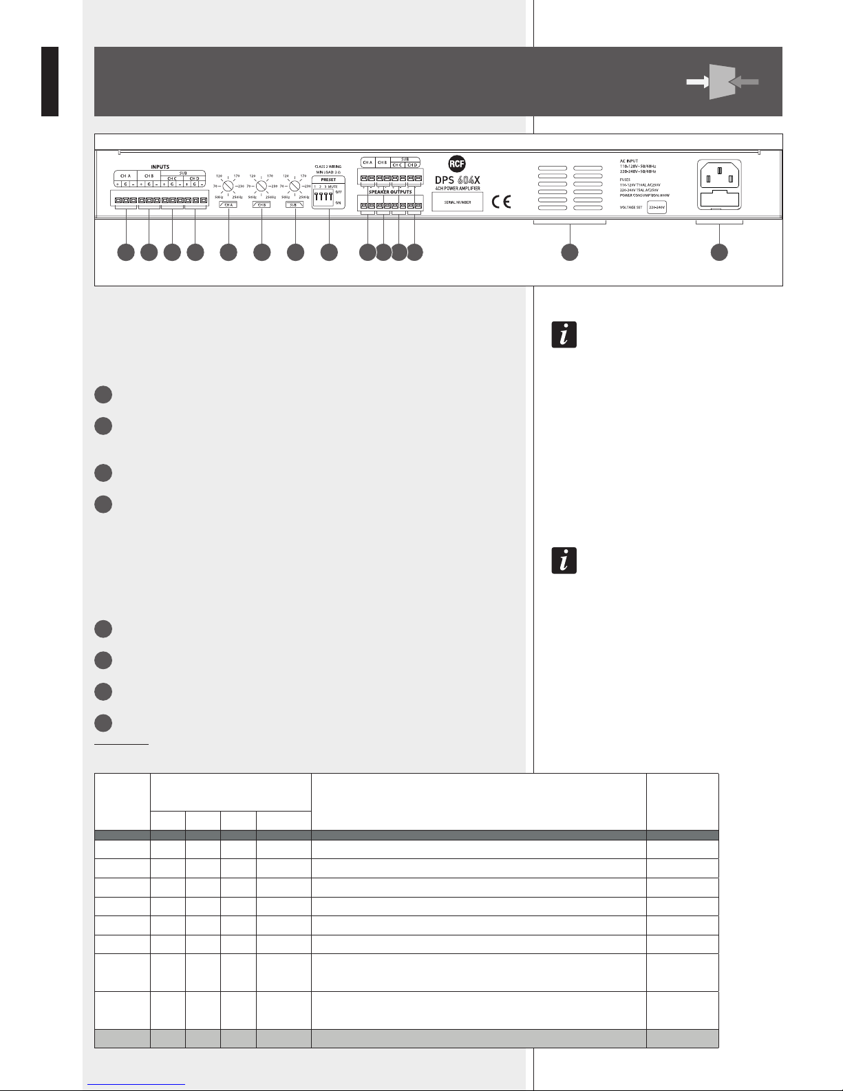
REAR PANEL
7 98 10 18 19 2011 1312 14 171615
INPUT EUROBLOCK CONNECTORS
audIo Inputs can Be connected to the euroBlock sockets By usIng the supplIed female connectors.
Balanced connectIon pIns: + (hot), – (cold), G (ground).
UnBalanced connectIon pIns: + (hot), G (ground).
7
CHANNEL A BALANCED AUDIO INPUT
8
CHANNEL B BALANCED AUDIO INPUT
Do not connect this input when channels A and B are bridged.
9
CHANNEL C BALANCED AUDIO INPUT
10
CHANNEL D BALANCED AUDIO INPUT
Do not connect this input when channels C and D are bridged.
INTERNAL CROSSOVER
the Internal crossover Is Inserted In modes 7 and 8 only.
It has two hI-pass fIlters (channels a and B) and a low-pass fIlter for suBwoofers.
the cutoff frequencIes can Be set In the range from 50 hz to 250 hz.
11
CHANNEL A HI-PASS FILTER CUTOFF FREQUENCY SELECTOR
12
CHANNEL B HI-PASS FILTER CUTOFF FREQUENCY SELECTOR
13
SUBWOOFER (ch. C-D) LOW-PASS FILTER CUTOFF FREQUENCY SELECTOR
14
PRESET DIP SWITCHES FOR OPERATION MODE SELECTION
Important: make sure the amplier is turned off before setting these dipswitches.
MODE
PRESET
DIP SWITCHES
DESCRIPTION
USED
INPUTS
1 2 3 MUTE
1 off off off off CH A-B-C-D: all indipendent. A B C D
2 ON off off off CH A-B-C-D: all linked. A
3 off ON off off CH A-B: bridged. CH C-D: bridged. A C
4 ON ON off off CH A-B: linked. CH C-D: linked. A C
5 off off ON off CH A-B: independent. CH C-D: bridged. A B C
6 ON off ON off CH A-B: linked. CH C-D: bridged. A C
7 off ON ON off
CH A-B: independent. CH C-D: bridged.
The internal crossover is inserted. SUB input: C
A B
(SUB: C)
8 ON ON ON off
CH A-B: independent. CH C-D: bridged.
The internal crossover is inserted. SUB input: A+B
A B
MUTE --- --- --- ON The amplier is muted / disabled.
Page 9

9
ENGLISH
DUAL EUROBLOCK CONNECTORS FOR SPEAKERS
The upper and the lower terminals are linked together (internally, in parallel), so these
can be used interchangeably (or both, when connecting more speakers to each channel).
Pins: + positive, – negative.
When channels A-B are bridged (mode 3), A+ is the positive and B+ is the negative.
When channels C-D are bridged (modes 3, 5, 6, 7, 8), C+ is the positive and D+ is the
negative.
The speaker impedance must not be lower than:
- 2 Ω, on independent or linked channels
- 4 Ω, when two channels are bridged.
15
CHANNEL A SPEAKER OUTPUTS
16
CHANNEL B SPEAKER OUTPUTS
17
CHANNEL C SPEAKER OUTPUTS
18
CHANNEL D SPEAKER OUTPUTS
19
VENT GRILL
Make sure it is not obstructed and there is enough room for a proper ventilation of the
amplier.
20
POWER CORD INPUT WITH FUSE
Connect the power cord only to a mains socket outlet with a protective earthing
connection.
The fuse must match that indicated on the rear panel silk screen.
Page 10

10
ENGLISH
OPERATION MODES
MODE 1: FOUR INDIPENDENT CHANNELS
All the four channels are completely independent (each channel input is only sent to its
respective speaker output).
Each front panel level control only affects its respective speaker output.
Minimum load impedance is 2 Ω per speaker output.
A
min. 2Ω
C
min. 2Ω
B
min. 2Ω
D
min. 2Ω
+
-
+
-
+
-
+
-
A B C D
A
min. 2Ω
A
min. 2Ω
A
min. 2Ω
A
min. 2Ω
+
-
+
-
+
-
+
-
A
MODE 2: FOUR LINKED CHANNELS
Channel A input signal is sent to all the four speaker outputs.
Each front panel level control affects its respective speaker output.
Minimum load impedance is 2 Ω per speaker output.
Page 11

11
ENGLISH
MODE 3: A-B BRIDGED, C-D BRIDGED
All channels are bridged (two pairs): the result is a doubling of the output voltage in
order to get a double power (on a double impedance load).
Each pair works with the same input signal:
channel A input for A-B channels
channel C input for C-D channels.
The output levels are adjusted by the channel A and C front panel controls (turn fully
counterclockwise the channel B and D controls).
Minimum load impedance is 4 Ω per speaker output.
Pay attention to the speaker wiring:
- channels A-B bridged: A+ is the positive and B+ is the negative
- channels C-D bridged: C+ is the positive and D+ is the negative.
MODE 4: A-B LINKED, C-D LINKED
- Channel A input signal is sent to both speakers outputs of channels A and B.
- Channel C input signal is sent to both speakers outputs of channels C and D.
Each front panel level control affects its respective speaker output.
Minimum load impedance is 2 Ω per speaker output.
A
min. 2Ω
C
min. 2Ω
A
min. 2Ω
C
min. 2Ω
+
-
+
-
+
-
+
-
A C
A
min. 4Ω
C
min. 4Ω
+
-
+
-
A C
C
Page 12

12
ENGLISH
MODE 5: A-B INDEPENDENT, C-D BRIDGED
CHANNELS A and B are completely independent and each of their front panel level
controls affects its respective speaker output only.
Minimum load impedance is 2 Ω per speaker output.
CHANNELS C and D are bridged with a common input signal (channel C input).
The result is a doubling of the output voltage in order to get a double power (on a double
impedance load). The output level is adjusted only by the channel C front panel control
(turn fully counterclockwise the channel D control). Minimum load impedance is 4 Ω.
Pay attention to the speaker wiring: C+ is the positive and D+ is the negative.
MODE 6: A-B LINKED, C-D BRIDGED
Like the mode 5, but CHANNELS A and B are linked. Channel A input signal is sent to
both speakers outputs of channels A and B. Each of their front panel level controls affects
its respective speaker output only. Minimum load impedance is 2 Ω per speaker output.
CHANNELS C and D are bridged with a common input signal (channel C input), see
mode 5.
Minimum load impedance is 4 Ω.
A
min. 2ΩBmin. 2Ω
+
-
+
-
+
-
A B C
min. 4Ω
C
A
min. 2ΩAmin. 2Ω
+
-
+
-
+
-
A C
min. 4Ω
C
Page 13

13
ENGLISH
MODE 7: A-B INDEPENDENT, C-D BRIDGED (FOR SUBWOOFERS)
INTERNAL CROSSOVER INSERTED, SUB INPUT: CHANNEL C
CHANNELS A and B are completely independent and each of their front panel level
controls affects its respective speaker output only. Both CH A and CH B hi-pass lters are
inserted. Minimum load impedance is 2 Ω per speaker output.
CHANNELS C and D are bridged with a common input signal (channel C input) to
subwoofers.
The result is a doubling of the output voltage in order to get a double power (on a double
impedance load). The output level is adjusted only by the channel C front panel control
(turn fully counterclockwise the channel D control). The SUB low-pass lter is inserted.
Subwoofer minimum impedance is 4 Ω.
Pay attention to the subwoofer wiring: C+ is the positive and D+ is the negative.
MODE 8: A-B INDEPENDENT, C-D BRIDGED (FOR SUBWOOFERS)
INTERNAL CROSSOVER INSERTED, SUB INPUT: CHANNELS A+B
Like the mode 7, but the common signal sent to subwoofers is the sum of channels A
and B.
All crossover lters are inserted.
CHANNELS A and B: minimum load impedance is 2 Ω per speaker output.
CHANNELS C and D: subwoofer minimum impedance is 4 Ω.
Pay attention to the subwoofer wiring: C+ is the positive and D+ is the negative.
A
min. 2ΩBmin. 2Ω
+
-
+
-
+
-
A B C
C
min. 4Ω
SUBWOOFER
A
min. 2ΩBmin. 2Ω
+
-
+
-
+
-
A B
A+B
min. 4Ω
SUBWOOFER
SUB
Page 14

14
ENGLISH
COOLING REQUIREMENTS
DPS 604X has a forced air cooling system to maintain a low operating temperature.
Make sure there is enough room in the front (and all around) of all ampliers.
As ampliers are rack-mounted, do not use doors or covers on the front and the rear of
rack cabinets.
SPECIFICATIONS
RMS OUTPUT POWER (single channels)
4 x 80 W @ 8 Ω
4 x 150 W @ 4 Ω
4 x 230 W @ 2 Ω
RATED OUTPUT POWER (bridged outputs)
2 x 300 W @ 8 Ω
2 x 400 W @ 4 Ω
Frequency response
20 Hz ÷ 14.1 kHz (+0/-3 dB) @ 2 Ω
20 Hz ÷ 24 kHz (+0.5/-3 dB) @ 4 Ω
20 Hz ÷ 33 kHz (+1.5/-3 dB) @ 8 Ω
Total harmonic distortion 0.1%
Signal / noise ratio > 95 dB
Amplier voltage gain 28 ±0.5 dB
Damping factor > 200
Crosstalk < 70 dB
Input impedance 20 kΩ (balanced), 10 kΩ (unbalanced)
Input sensitivity 0.9-1.1 V (0±1dBV)
Protections
Short circuit, open circuit, thermal drift, ultrasonic, RF
protection, reactive or mismatched loads, internal fuses.
Connectors Euroblock
Operating voltage 115 / 230 V (according to the model), 50/60 Hz
Dimensions (w, h, d) 483 mm, 44 mm, 281 mm (1U – 19” rack)
Net weight 4.5 kg
Page 15

Page 16

16
ITALIANO
IMPORTANTE
Prima di collegare ed utilizzare questo prodotto, leggere attentamente le istruzioni contenute
in questo manuale, il quale è da conservare per riferimenti futuri.
Il presente manuale costituisce parte integrante del prodotto e deve accompagnare
quest’ultimo anche nei passaggi di proprietà, per permettere al nuovo proprietario
di conoscere le modalità d’installazione e d’utilizzo e le avvertenze per la sicurezza.
L’installazione e l’utilizzo errati del prodotto esimono la RCF S.p.A. da ogni responsabilità.
ATTENZIONE: per prevenire i rischi di amme o scosse elettriche, non esporre mai questo
prodotto alla pioggia o all’umidità; questo apparecchio è progettato per il solo uso all’interno.
AVVERTENZE PER LA SICUREZZA
1. Tutte le avvertenze, in particolare quelle relative alla sicurezza, devono essere lette con
particolare attenzione, in quanto contengono importanti informazioni.
2. ALIMENTAZIONE DA RETE ELETTRICA
- La tensione di alimentazione dell’apparecchio ha un valore sufcientemente alto da
costituire un rischio di folgorazione per le persone: non procedere mai all’installazione
od alla connessione dell’apparecchio con il cavo dell’alimentazione collegato alla rete
elettrica.
- Prima di alimentare questo prodotto, assicurarsi che tutte le connessioni siano corrette
e che la tensione della vostra rete di alimentazione corrisponda quella di targa
dell’apparecchio, in caso contrario rivolgetevi ad un rivenditore RCF.
- Le parti metalliche dell’apparecchio sono collegate a terra tramite il cavo di alimentazione.
Un apparecchio avente costruzione di CLASSE I deve essere connesso alla presa di rete
con un collegamento alla terra di protezione.
- Accertarsi che il cavo di alimentazione dell’apparecchio non possa essere calpestato o
schiacciato da oggetti, al ne di salvaguardarne la perfetta integrità.
- Per evitare il rischio di shock elettrici, non aprire mai l’apparecchio: all’interno non vi
sono parti che possono essere utilizzate dall’utente.
- La spina del cavo d’alimentazione è utilizzata come dispositivo di scollegamento e deve
rimanere sempre facilmente accessibile.
3. Impedire che oggetti o liquidi entrino all’interno del prodotto, perché potrebbero causare
un corto circuito. L’apparecchio non deve essere esposto a stillicidio o a spruzzi d’acqua;
nessun oggetto pieno di liquido (quali vasi) e nessuna sorgente di amma nuda (es. candele
accese) deve essere posto sull’apparecchio.
4. Non eseguire sul prodotto interventi / modiche / riparazioni se non quelle espressamente
descritte sul manuale istruzioni.
Contattare centri di assistenza autorizzati o personale altamente qualicato quando:
- l’apparecchio non funziona (o funziona in modo anomalo);
- il cavo di alimentazione ha subito gravi danni;
- oggetti o liquidi sono entrati nell’apparecchio;
- l’apparecchio ha subito forti urti.
5. Qualora questo prodotto non sia utilizzato per lunghi periodi, scollegare il cavo
d’alimentazione dalla rete elettrica.
6. Nel caso che dal prodotto provengano odori anomali o fumo, spegnerlo immediatamente
e scollegare il cavo d’alimentazione.
7. I terminali marcati con il simbolo
sono da ritenersi ATTIVI e PERICOLOSI ed il loro
collegamento deve essere effettuato da PERSONE ADDESTRATE oppure si devono utilizzare
cavi già pronti.
IMPORTANTE
ATTENZIONE
AVVERTENZE PER
LA SICUREZZA
Page 17

17
ITALIANO
8. Non collegare a questo prodotto altri apparecchi e accessori non previsti.
Quando è prevista l’installazione sospesa, utilizzare solamente gli appositi punti di ancoraggio
e non cercare di appendere questo prodotto tramite elementi non idonei o previsti allo scopo.
Vericare inoltre l’idoneità del supporto (parete, softto, struttura ecc., al quale è ancorato
il prodotto) e dei componenti utilizzati per il ssaggio (tasselli, viti, staffe non fornite da
RCF ecc.) che devono garantire la sicurezza dell’impianto / installazione nel tempo, anche
considerando, ad esempio, vibrazioni meccaniche normalmente generate da un trasduttore.
Per evitare il pericolo di cadute, non sovrapporre fra loro più unità di questo prodotto, quando
questa possibilità non è espressamente contemplata dal manuale istruzioni.
9. RCF S.p.A. raccomanda vivamente che l’installazione di questo prodotto sia eseguita
solamente da installatori professionali qualicati (oppure da ditte specializzate) in grado di
farla correttamente e certicarla in accordo con le normative vigenti.
Tutto il sistema audio dovrà essere in conformità con le norme e le leggi vigenti in materia
di impianti elettrici.
10. Sostegni e Carrelli
Se previsto, il prodotto va utilizzato solo su carrelli o sostegni consigliati dal produttore.
L’insieme apparecchio-sostegno / carrello va mosso con estrema cura. Arresti improvvisi, spinte
eccessive e superci irregolari o inclinate possono provocare il ribaltamento dell’assieme.
11. Si devono considerare anche i fattori meccanici ed elettrici quando si installa un sistema
audio professionale (oltre a quelli prettamente acustici, come la pressione sonora, gli angoli
di copertura, la risposta in frequenza, ecc.).
12. Perdita dell’udito
L’esposizione ad elevati livelli sonori può provocare la perdita permanente dell’udito. Il livello
di pressione acustica pericolosa per l’udito varia sensibilmente da persona a persona e
dipende dalla durata dell’esposizione. Per evitare un’esposizione potenzialmente pericolosa
ad elevati livelli di pressione acustica, è necessario che chiunque sia sottoposto a tali livelli
utilizzi delle adeguate protezioni; quando si fa funzionare un trasduttore in grado di produrre
elevati livelli sonori è necessario indossare dei tappi per orecchie o delle cufe protettive.
Consultare i dati tecnici contenuti nei manuali istruzioni per conoscere le massime pressioni
sonore che i diffusori acustici sono in grado di produrre.
13. Non ostruire le griglie di ventilazione dell’unità. Collocare il prodotto lontano da fonti di
calore e garantire la circolazione dell’aria in corrispondenza delle griglie di aerazione.
14. Non sovraccaricare gli amplicatori; vericare che non via sia una o più uscite in
cortocircuito.
15. Non forzare mai gli organi di comando (tasti, manopole ecc.).
16. Non usare solventi, alcool, benzina o altre sostanze volatili per la pulitura delle parti
esterne dell’unità, ma un panno asciutto.
Per evitare fenomeni di rumorosità indotta sui cavi che trasportano segnali dai microfoni o
di linea (per esempio 0dB), usare solo cavi schermati ed evitare di posarli nelle vicinanze di:
- apparecchiature che producono campi elettromagnetici di forte intensità;
- cavi di rete;
- linee che alimentano altoparlanti.
NOTA SUI CAVI PER SEGNALI AUDIO
Page 18

18
ITALIANO
RCF S.P.A. VI RINGRAZIA PER L’ACQUISTO DI QUESTO PRODOTTO, REALIZZATO
IN MODO DA GARANTIRNE L’AFFIDABILITÀ E PRESTAZIONI ELEVATE.
DESCRIZIONE
DISIMBALLO ED INSTALLAZIONE
DPS 604X è un amplicatore in “classe D”, un nale di potenza avente quattro canali
indipendenti, di dimensioni compatte (un’unità rack 19”) e leggero, per uso professionale
in sistemi installati.
La sua potenza nominale è 230 W RMS su 2 Ω per ciascuno dei quattro canali (2 x 400 W
RMS a ponte su 4 Ω).
CARATTERISTICHE PRINCIPALI:
- risposta rapida e bassa distorsione;
- otto differenti modi di funzionamento, due dei quali con crossover interno;
- protezioni interne assicuranti alta afdabilità e sicurezza;
- connettori Euroblock sia per gli ingressi audio sia per le uscite amplicate
(per il collegamento dei diffusori acustici).
Vericare se il cartone per l’imballo ed il contenuto hanno subito dei danni durante il
trasporto (nel caso che l’amplicatore sia danneggiato, informare immediatamente il
rivenditore e lo spedizioniere).
È sempre consigliabile tenere il materiale d’imballo, perno nel caso che l’amplicatore sia
arrivato in buone condizioni.
I cavi per gli ingressi audio e le uscite amplicate non sono inclusi.
Ciascun amplicatore occupa una singola unità di un rack standard 19”.
L’AMPLIFICATORE NON DOVREBBE ESSERE POSTO IN LUOGHI CON:
- temperatura troppo elevata, polvere o umidità eccessiva;
- macchine del fumo con l’uscita orientata verso l’amplicatore;
- uscite d’aria riscaldata;
- vibrazioni permanenti;
- forti campi elettromagnetici (dovuti a trasformatori, trasmettitori, ecc.).
Page 19

19
ITALIANO
PANNELLO FRONTALE
1
Interruttore principale POWER dell’amplicatore (ON: acceso; OFF: spento).
Prima di accendere l’amplicatore, controllare tutte le connessioni e ruotare
completamente in senso antiorario i controlli di livello 3 di tutti i quattro canali.
2
LED POWER: indica l’accensione dell’amplicatore.
3
Quattro controlli (uno per ogni canale) per la regolazione del livello d’uscita dei
rispettivi canali dell’amplicatore.
Ruotarli in senso orario per aumentare i livelli d’uscita (28 dB = livello massimo) od
antiorario per diminuirli.
Impostare il livello di un canale inutilizzato su -∞ (ruotare il controllo completamente in
senso antiorario).
se I canalI a e B sono messI “a ponte”, usare solo Il controllo del canale a; se I canalI c e d sono
messI “a ponte”, usare solo Il controllo del canale c.
4
LED SIGNAL: quando acceso, indica la presenza del segnale nel rispettivo ingresso.
5
CLIP LED: indicatore di “clipping” che si accende quando la distorsione del segnale
nel rispettivo canale eccede lo 0,5%; in tal caso, il livello del segnale è troppo alto ed è
necessario diminuire il rispettivo volume (ruotare in senso antiorario il controllo
3
).
6
LED PROTECT: indicatore di inserimento della protezione; la rispettiva uscita è
disattivata.
Assicurarsi che la griglia di ventilazione
19
non sia ostruita e che vi sia spazio sufciente
per la corretta aerazione dell’amplicatore; controllare inoltre il cavo per il collegamento
ai diffusori acustici.
3 3 3 31
2
6 6
4 4
5 5
Page 20

20
ITALIANO
PANNELLO POSTERIORE
CONNETTORI EUROBLOCK DEGLI INGRESSI AUDIO
glI IngressI audIo sI collegano tramIte I connettorI euroBlock In dotazIone.
contattI per Il collegamento Bilanciato: + (posItIvo), – (negatIvo), G (massa).
contattI per Il collegamento sBilanciato: + (posItIvo), G (massa).
7
INGRESSO AUDIO BILANCIATO DEL CANALE A
8
INGRESSO AUDIO BILANCIATO DEL CANALE B
Non collegare questo ingresso quando i canali A e B sono messi “a ponte”.
9
INGRESSO AUDIO BILANCIATO DEL CANALE C
10
INGRESSO AUDIO BILANCIATO DEL CANALE D
Non collegare questo ingresso quando i canali C e D sono messi “a ponte”.
CROSSOVER INTERNO
Il crossover Interno è InserIto solo nelle modalItà dI funzIonamento 7 e 8.
sono presentI due fIltrI passa-alto (canalI a e B, per dIffusorI “satellItI”) ed un passa-Basso per
suBwoofer; le frequenze dI taglIo sono ImpostaBIlI da 50 hz a 250 hz.
11
SELETTORE FREQUENZA DI TAGLIO DEL FILTRO PASSA-ALTO (CANALE A)
12
SELETTORE FREQUENZA DI TAGLIO DEL FILTRO PASSA-ALTO (CANALE B)
13
SELETTORE FREQUENZA DI TAGLIO DEL FILTRO PASSA-BASSO PER
SUBWOOFER (CANALI C-D)
14
MICROINTERRUTTORI (dip-switch) “PRESET” PER LA SELEZIONE DELLE
MODALITÀ DI FUNZIONAMENTO
Importante: assicurarsi che l'amplicatore sia spento prima di impostare i
dip-switch.
MODO
PRESET
DIP SWITCH
DESCRIZIONE
INGRESSI
USATI
1 2 3 MUTE
1 off off off off canali A-B-C-D: tutti indipendenti. A B C D
2 ON off off off canali A-B-C-D: tutti uniti tra loro. A
3 off ON off off canali A-B: “a ponte”; canali C-D: “a ponte”. A C
4 ON ON off off canali A-B: uniti; canali C-D: uniti. A C
5 off off ON off canali A-B: indipendenti; canali C-D: “a ponte”. A B C
6 ON off ON off canali A-B: uniti; canali C-D: “a ponte”. A C
7 off ON ON off
canali A-B: indipendenti; canali C-D: “a ponte”.
Il crossover interno è inserito; ingresso SUB: C .
A B
(SUB: C)
8 ON ON ON off
canali A-B: indipendenti. canali C-D: “a ponte”.
Il crossover interno è inserito; ingresso SUB: A+B
A B
MUTE --- --- --- ON L’amplicatore è disattivato.
7 98 10 18 19 2011 1312 14 171615
Page 21

21
ITALIANO
DOPPIO CONNETTORE EUROBLOCK PER I COLLEGAMENTI AI DIFFUSORI
ACUSTICI
Il terminale superiore e quello inferiore sono internamente collegati insieme (in parallelo),
pertanto possono essere usati indifferentemente (od entrambi, per comodità, ad esempio
quando si collegano più diffusori a ciascun canale).
Contatti: + positivo, – negativo.
Quando i canali A e B sono messi “a ponte” (modalità 3), A+ è il contatto positivo e B+
quello negativo; quando i canali C e D sono messi “a ponte” (modalità 3, 5, 6, 7, 8), C+
è il contatto positivo e D+ quello negativo.
L'impedenza complessiva dei diffusori acustici non deve essere inferiore a:
- 2 Ω, all'uscita di un singolo canale indipendente (od unito ad altri);
- 4 Ω, all'uscita comune di due canali messi “a ponte”.
15
USCITE DIFFUSORI ACUSTICI CANALE A
16
USCITE DIFFUSORI ACUSTICI CANALE B
17
USCITE DIFFUSORI ACUSTICI CANALE C
18
USCITE DIFFUSORI ACUSTICI CANALE D
19
GRIGLIA PER LA VETILAZIONE
Assicurarsi che la griglia non sia ostruita e che via sia sufciente spazio per l'aerazione
corretta dell'amplicatore.
20
INGRESSO PER IL CAVO D'ALIMENTAZIONE / PORTAFUSIBILE
Collegare il cavo d'alimentazione solo ad una presa di rete avente la messa a terra.
Il fusibile di protezione deve corrispondere ai dati di targa riportati sulla serigraa del
pannello posteriore.
Page 22

22
ITALIANO
MODALITÀ DI FUNZIONAMENTO
MODO 1: QUATTRO CANALI INDIPENDENTI
Tutti i quattro canali sono completamente indipendenti ed ogni controllo di livello
(sul pannello frontale) agisce solo sulla rispettiva uscita altoparlanti.
L’impedenza minima ammessa del carico è 2 Ω per ogni uscita altoparlanti.
MODO 2: UNICO SEGNALE INVIATO AI QUATTRO CANALI UNITI TRA LORO
Il segnale audio d'ingresso del canale A è inviato a tutte le quattro uscite altoparlanti.
Ogni controllo di livello (sul pannello frontale) agisce solo sulla rispettiva uscita
altoparlanti.
L'impedenza minima ammessa del carico è 2 Ω per ogni uscita altoparlanti.
A
min. 2Ω
C
min. 2Ω
B
min. 2Ω
D
min. 2Ω
+
-
+
-
+
-
+
-
A B C D
A
min. 2Ω
A
min. 2Ω
A
min. 2Ω
A
min. 2Ω
+
-
+
-
+
-
+
-
A
Page 23

23
ITALIANO
MODO 3: DUE COPPIE DI CANALI MESSE A PONTE (A-B, C-D)
Tutti i canali sono messi “a ponte” (due coppie): questo comporta un raddoppio della
tensione d’uscita per ottenere una potenza doppia (su un carico avente impedenza
doppia).
Ciascuna coppia di canali ha in comune lo stesso segnale d’ingresso:
- quello del canale A per la coppia A-B;
- quello del canale C per la coppia C-D.
I livelli d’uscita sono regolabili solo dai controlli dei canali A e C posti sul pannello
frontale (ruotare completamente in senso antiorario i controlli di livello dei canali B e D).
L’impedenza minima ammessa del carico è 4 Ω per ogni uscita altoparlanti.
Prestare attenzione al collegamento dei diffusori acustici alle uscite dell’amplicatore:
- canali A-B “a ponte”, A+ è il contatto positivo e B+ quello negativo;
- canali C-D “a ponte”, C+ è il contatto positivo e D+ quello negativo.
MODO 4: CANALI A-B UNITI, CANALI C-D UNITI
Il segnale audio d'ingresso del canale A è inviato ad entrambe le uscite altoparlanti dei
canali A e B.
Il segnale audio d'ingresso del canale C è inviato ad entrambe le uscite altoparlanti dei
canali C e D.
Ogni controllo di livello (sul pannello frontale) agisce solo sulla rispettiva uscita
altoparlanti.
L'impedenza minima ammessa del carico è 2 Ω per ogni uscita altoparlanti.
A
min. 2Ω
C
min. 2Ω
A
min. 2Ω
C
min. 2Ω
+
-
+
-
+
-
+
-
A C
A
min. 4Ω
C
min. 4Ω
+
-
+
-
A C
C
Page 24

24
ITALIANO
MODO 5: CANALI A-B INDIPENDENTI, CANALI C-D A PONTE
CANALI A e B: sono completamente indipendenti e ciascuno dei due controlli di livello
(sul pannello frontale) agisce solo sulla rispettiva uscita altoparlanti.
L'impedenza minima ammessa del carico è 2 Ω per ogni uscita altoparlanti.
CANALI C e D: questi sono messi “a ponte” e hanno in comune lo stesso segnale
d'ingresso (quello del canale C), ciò comporta un raddoppio della tensione d'uscita per
ottenere una potenza doppia (su un carico avente impedenza doppia).
Il livello d'uscita è regolabile solo dal controllo del canale C posto sul pannello frontale
(ruotare completamente in senso antiorario il controllo di livello del canale D).
L'impedenza minima ammessa del carico è 4 Ω.
Prestare attenzione al collegamento dei diffusori acustici alle uscite dell'amplicatore: C+
è il contatto positivo e D+ quello negativo.
MODO 6: CANALI A-B UNITI, CANALI C-D A PONTE
Come il modo 5, ma i CANALI A e B sono uniti. Il segnale audio d'ingresso del canale A
è inviato ad entrambe le uscite altoparlanti dei canali A e B e ciascuno dei due controlli di
livello (sul pannello frontale) agisce solo sulla rispettiva uscita altoparlanti.
L'impedenza minima ammessa del carico è 2 Ω per ogni uscita altoparlanti.
I CANALI C e D sono messi “a ponte” (ingresso comune: canale C), vedere il modo 5.
L'impedenza minima ammessa del carico è 4 Ω.
A
min. 2ΩBmin. 2Ω
+
-
+
-
+
-
A B C
min. 4Ω
C
A
min. 2ΩAmin. 2Ω
+
-
+
-
+
-
A C
min. 4Ω
C
Page 25

25
ITALIANO
MODO 7: CANALI A-B INDIPENDENTI, CANALI C-D A PONTE (PER SUBWOOFER)
CROSSOVER INTERNO INSERITO; INGRESSO SUB: CANALE C
CANALI A e B: sono completamente indipendenti e ciascuno dei due controlli di livello
(sul pannello frontale) agisce solo sulla rispettiva uscita altoparlanti.
Entrambi i ltri passa-alto dei canali A e B sono inseriti.
L'impedenza minima ammessa del carico è 2 Ω per ogni uscita altoparlanti.
CANALI C e D (SUB): questi sono messi “a ponte” e hanno in comune lo stesso segnale
d'ingresso (quello del canale C), ciò comporta un raddoppio della tensione d'uscita
per ottenere una potenza doppia (su un carico avente impedenza doppia). Il livello
d'uscita è regolabile solo dal controllo del canale C posto sul pannello frontale (ruotare
completamente in senso antiorario il controllo di livello del canale D). Il ltro passa-basso
per il/i subwoofer è inserito.
L'impedenza minima complessiva dei subwoofer è 4 Ω.
Prestare attenzione al collegamento del/dei subwoofer alle uscite dell'amplicatore: C+ è
il contatto positivo e D+ quello negativo.
MODO 8: CANALI A-B INDIPENDENTI, CANALI C-D A PONTE (PER SUBWOOFER)
CROSSOVER INTERNO INSERITO; INGRESSO SUB: CANALI A+B
Come il modo 7, ma il segnale comune inviato al/ai subwoofer è la somma dei canali A più B.
Tutti i ltri del crossover sono inseriti.
CANALI A e B: l'impedenza minima ammessa del carico è 2 Ω per ogni uscita altoparlanti.
CANALI C e D: l'impedenza minima complessiva dei subwoofer è 4 Ω.
Prestare attenzione al collegamento del/dei subwoofer alle uscite dell'amplicatore:
C+ è il contatto positivo e D+ quello negativo.
A
min. 2ΩBmin. 2Ω
+
-
+
-
+
-
A B
A+B
min. 4Ω
SUBWOOFER
A
min. 2ΩBmin. 2Ω
+
-
+
-
+
-
A B C
C
min. 4Ω
SUBWOOFER
SUB
Page 26

26
ITALIANO
VENTILAZIONE
L’amplicatore DPS 604X ha un sistema di raffreddamento con ventilazione forzata per
mantenere una bassa temperatura di funzionamento.
Assicurarsi che vi sia spazio sufciente sia davanti il pannello frontale sia tutt’intorno.
Data l’installazione in un armadio rack, non utilizzare porte (od altre coperture) sia sul lato
anteriore sia su quello posteriore.
DATI TECNICI
POTENZA NOMINALE D’USCITA RMS
(singoli canali)
4 x 80 W su 8 Ω
4 x 150 W su 4 Ω
4 x 230 W su 2 Ω
POTENZA NOMINALE D’USCITA RMS
(“a ponte”)
2 x 300 W su 8 Ω
2 x 400 W su 4 Ω
Risposta in frequenza
20 Hz ÷ 14,1 kHz (+0/-3 dB) su 2 Ω
20 Hz ÷ 24 kHz (+0,5/-3 dB) su 4 Ω
20 Hz ÷ 33 kHz (+1,5/-3 dB) su 8 Ω
Distorsione (T.H.D.) 0,10%
Rapporto segnale / rumore > 95 dB
Guadagno dell’amplicatore 28 ±0,5 dB
Fattore di smorzamento > 200
Diafonia tra canali < 70 dB
Impedenza d’ingresso
20 kΩ (bilanciato), 10 kΩ (sbilanciato)
Sensibilità ingressi 0,9-1,1 V (0±1dBV)
Protezioni
Cortocircuito, circuito aperto, deriva termica, ultrasuoni,
radiofrequenza, carichi reattivi o non corrispondenti,
fusibili interni.
Connettori Euroblock
Tensione di funzionamento 115 / 230 V (secondo il modello), 50/60 Hz
Dimensioni (l, h, p) 483 mm, 44 mm, 281 mm (un’unità rack 19”)
Peso netto 4,5 kg
Page 27

Page 28

10307561 revB
2016 / 11
www.rcf.it
RCF S.p.A. Italy
Via Raffaello Sanzio, 13
42124 Reggio Emilia - Italy
Tel +39 0522 274 411
Fax +39 0522 232 428
e-mail: info@rcf.it
Salvo eventuali errori ed omissioni.
RCF S.p.A. si riserva il diritto di apportare modiche senza preavviso.
Except possible errors and omissions.
RCF S.p.A. reserves the right to make modications without prior notice.
 Loading...