

Page 1

USER MANUAL
MANUALE D’USO
BM 3022
PRE-AMPLIFIED
DESK-TOP PAGING
MICROPHONE
BASE MICROFONICA
PREAMPLIFICATA DA
TAVOLO
Page 2

Page 3

INDEX
INDICE
ENGLISH
SAFETY PRECAUTIONS
DESCRIPTION
OPERATION AND INTERNAL SETTINGS
REAR PANEL AND CONNECTIONS
FRONT PANEL
SPECIFICATIONS
ITALIANO
AVVERTENZE PER LA SICUREZZA
DESCRIZIONE
FUNZIONAMENTO ED IMPOSTAZIONI ALL’INTERNO
PANNELLO POSTERIORE E COLLEGAMENTO
PANNELLO FRONTALE
DATI TECNICI
4
5
5
9
11
12
14
15
15
19
21
22
Page 4

4
ENGLISH
IMPORTANT NOTES
SAFETY
PRECAUTIONS
IMPORTANT NOTES
Before connecting and using this paging microphone, please read this instruction
manual carefully and keep it on hand for future reference. The manual is to be
considered an integral part of this product and must accompany it when changing
ownership as a reference for correct installation and use as well as for the safety
precautions.
RCF S.p.A. will not assume any responsibility for the incorrect installation and / or use
of this product.
SAFETY PRECAUTIONS
1. All the precautions, in particular the safety ones, must be read with special attention,
as they provide important information.
2. Make sure all connections have been made correctly before switching all devices on.
Do not connect / disconnect the paging microphone when the system is operating.
3. Protect paging microphone cables from damage and assure they are positioned
where these cannot be stepped on or crushed by objects.
4. Do not put the paging microphone into water (or another liquid), do not throw it.
5. Never attempt to carry out any operations, modifications or repairs.
If the paging microphone does not work properly, contact your authorized service centre.
6. Should the paging microphone emit any strange odour or even smoke, turn the sound
system off immediately, disconnect the paging microphone and its adapter from the
mains.
7. RCF S.p.A. strongly recommends the sound system installation is only made by
professional qualified installers (or specialised firms), who can certify it according to the
regulations in force.
The entire audio system must comply with the current standards and regulations
regarding electrical systems.
8. There are numerous mechanical and electrical factors to be considered when
installing a professional audio system (in addition to those which are strictly acoustic,
such as sound pressure, angles of coverage, frequency response, etc.).
9. Do not point the microphone at near loudspeakers, in order to avoid feedback.
10. Hearing loss
Exposure to high sound levels can cause permanent hearing loss. The acoustic pressure
level that leads to hearing loss is different from person to person and depends on the
duration of exposure.
To prevent potentially dangerous exposure to high levels of acoustic pressure, anyone
who is exposed to these levels should use adequate protection devices.
When a transducer capable of producing high sound levels is being used, it is therefore
necessary to wear ear plugs or protective earphones.
11. To prevent inductive effects from causing hum, noise and a bad system operating,
paging microphone cables should not be laid together with other electric cables (mains)
and loudspeaker lines.
12. Keep the paging microphone far from any excessive heat source.
13. Do not use solvents, alcohol, benzene or other volatile substances for cleaning the
external parts. Just use a dry cloth.
Page 5

5
ENGLISH
RCF S.P.A. THANKS YOU FOR PURCHASING THIS PRODUCT, WHICH
HAS BEEN DESIGNED TO GUARANTEE RELIABILITY AND HIGH
PERFORMANCE.
BM 3022 is a pre-amplified desk-top paging microphone with an electret capsule.
Its output audio signal level (balanced and adjustable through a trimmer) allows
its connection to “line” inputs of mixer-amplifiers, even for long distances
(up to 1 km / c. 3300 ft) through CAT5 cable.
Every paging microphone has an automatic gain control (AGC), a compressor /
limiter that (if enabled) normalizes the microphone signal level, regardless of the
voice intensity.
Up to 30 BM 3022 paging microphones can be linked in series (‘daisy-chain’, in
a single line) and used either in mixing (more microphones activated at the same
time) or in interlocking (only a single microphone activated at a time).
One or more paging microphones can have priority and be activated at any time,
disabling all other paging microphones without priority.
When activating a microphone, the announcement can be preceded by a chime.
A RCF AC AD2405 adapter (24 V dc) is included. This can be used a power
supply unit for max. 4 BM 3022 paging microphones.
Before connecting each BM 3022 paging microphone, it is necessary to set its
internal dip-switches (according to the chosen operation and options).
Unscrew the 6 fixing screws of the rear cover to open the paging microphone
and access the 8 dip-switches.
DESCRIPTION
OPERATION AND INTERNAL SETTINGS
THE 6 SCREWS
OF THE REAR COVERDIP-SWITCHES
Page 6
6
ENGLISH
DIP-SWITCH no. 1: AGC (Automatic Gain Control)
Compressor / limiter that (if enabled) normalizes the microphone signal level,
regardless of the voice intensity.
Suggested setting: ON.
DIP-SWITCH no.2: Priority
Priority of the BM 3022 paging microphone on all the others (without priority)
linked in the same line.
The paging microphone(s) having priority can engage the audio channel at any
time, temporarily disabling all the other paging microphones without priority.
When the system is set to the ‘interlocking’ mode (all dip-switches no.3 set to
‘I/Lock’), only one paging microphone with priority can be activated (the first in
chronological order).
DIP-SWITCH no.3: Mixing mode (Mix) – Interlocking mode (I/Lock)
This seTTing is necessary when 2 or more Bm 3022 paging microphones are linked TogeTher
in The same line.
All paging microphone dip-switches no.3 shall have the same setting (either
‘Mix’ or ‘I/Lock’).
Mixing mode: in a line made of 2 or more BM 3022 paging microphones, the
audio signal of each microphone (if activated through the TALK button) is always
mixed (on the shared audio channel) with all the others.
Interlocking mode: in a line made of 2 or more BM 3022 paging microphones,
only one at a time can be activated (the first in chronological order). The ‘busy’
indication (LED: flashing red) will appear on all the other paging microphones,
which will need to wait until the line is available again.
The paging microphones having prioriTy are excepTions: These can engage The audio channel
aT any Time and Temporarily disaBle all The oTher paging microphones wiThouT prioriTy.
when The sysTem is seT To The ‘inTerlocking’ mode, only one paging microphone wiTh prioriTy
can Be acTivaTed (The firsT in chronological order).
ON
ON
I/Lock: interlocking
ON
ON
Low: low sensitivity
(high threshold)
Long: 30 s
ON
1
2
3
4
5
6
7
8
AGC – Automatic gain control
Priority
Mixing / Interlocking mode
Chime
VOX function
VOX Level (sensitivity)
VOX Release time
SMART PTT – TALK button toggling
OFF
OFF
Mix: mixing
OFF
OFF
Hi: high sensitivity
(low threshold)
(Short): 3 s
OFF
Page 7

7
ENGLISH
DIP-SWITCH no.4: Chime
If enabled, when pressing the TALK button, the chime is played (preceding an
announcement).
The chime level is adjustable through the dedicated trimmer.
DIP-SWITCH no.5: VOX function
If the VOX function is enabled, after pressing the TALK button, the microphone will automatically get open only if its capsule detects a sound with a level
that exceeds the predetermined threshold and will be automatically muted
(after the ‘VOX Release time’, see dip-switch no.7) as soon as the sound level
returns below the threshold.
The vox funcTion can Be useful To avoid possiBle acousTic feedBacks (‘ larsen effecT’),
as microphones are muTed when noT used.
DIP-SWITCH no.6: VOX Level (sensitivity)
It allows to choose the VOX sensitivity between 2 levels:
- Hi: high sensitivity (low threshold), the microphone gets open with low voice
- Low: low sensitivity (high threshold), the microphone gets open with loud
voice.
DIP-SWITCH no.7: VOX Release time
Setting of the VOX release time, which is the time between the absence of
a sound with a level above the predetermined threshold and the automatic
closing of the microphone.
The options are:
- (Short): 3 seconds, suitable for conferences, where each microphone gets
muted immediately after the intervention of the speaker.
- Long: the microphone stays open for at least 30 seconds even if the sound is
absent, then the paging microphone is automatically disabled (like pressing
the TALK button again).
This mode is preferable if paging microphones are mainly used for
announcements.
DIP-SWITCH no.8: SMART PTT – TALK button toggling
The TALK button turns the microphone on.
If this dip-switch is set to OFF, the TALK button must be held down when
speaking (and released at the end).
If this dip-switch is set to ON, the TALK button operates in ‘SMART’ mode,
allowing to toggle it:
- If the TALK button is pressed and quickly released, the microphone will be
turned on / off (‘toggle’).
- If the TALK is pressed and held down, the microphone will stay open until
the TALK button release (even if it has been previously activated as ‘toggle’).
Page 8
8
ENGLISH
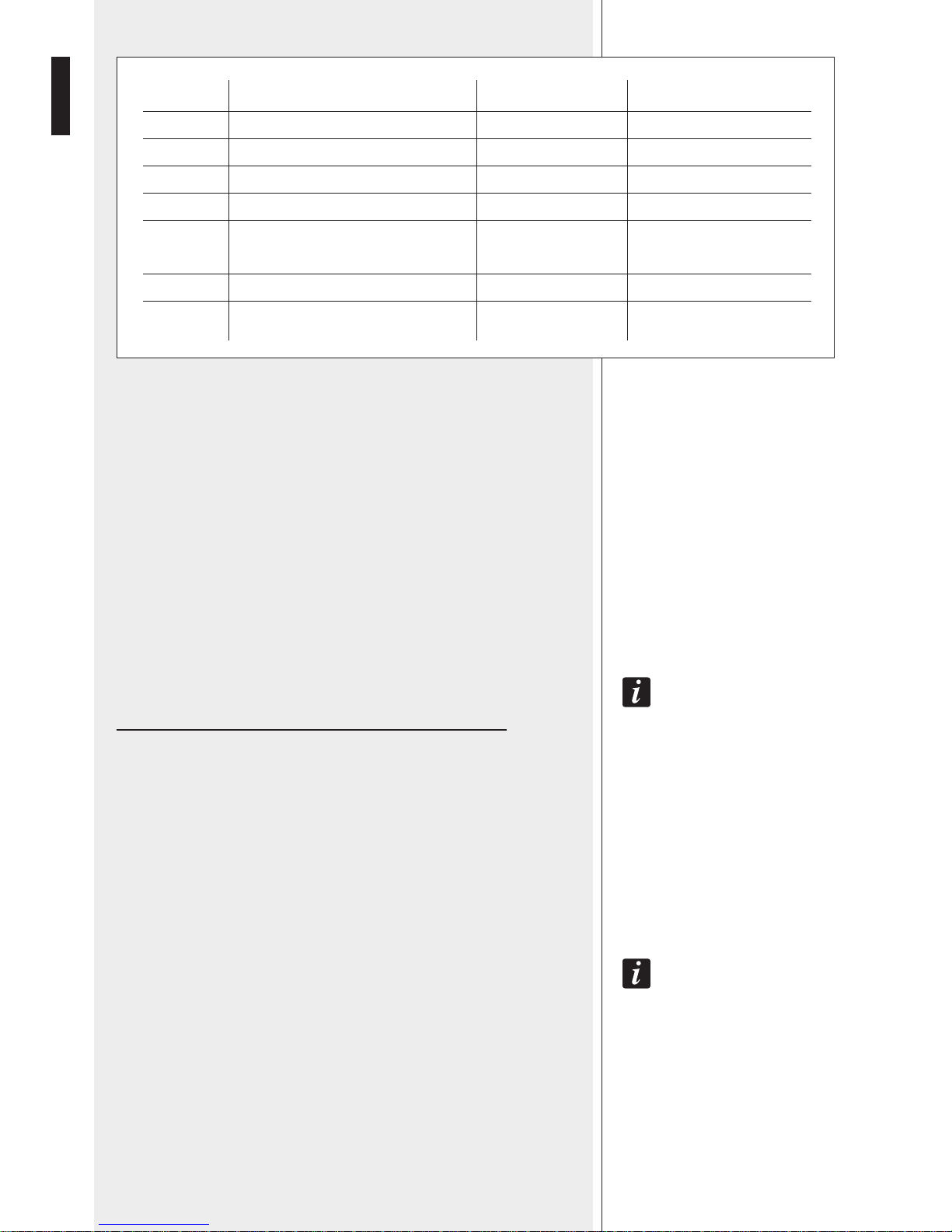
EXAMPLES
— SUPERMARKET
A BM 3022 paging microphone is placed on every cash desk.
All paging microphones are linked in series (‘daisy-chain’) and interlocked
one another.
Dip-switch 2 and 3 settings on all paging microphones:
- dip-switch no.2: OFF (no priority)
- dip-switch no.3: I/Lock (interlocking mode)
As option, it is possible to add a BM 3022 paging microphone having priority
(dip-switch no.2 set to ON) for the head office.
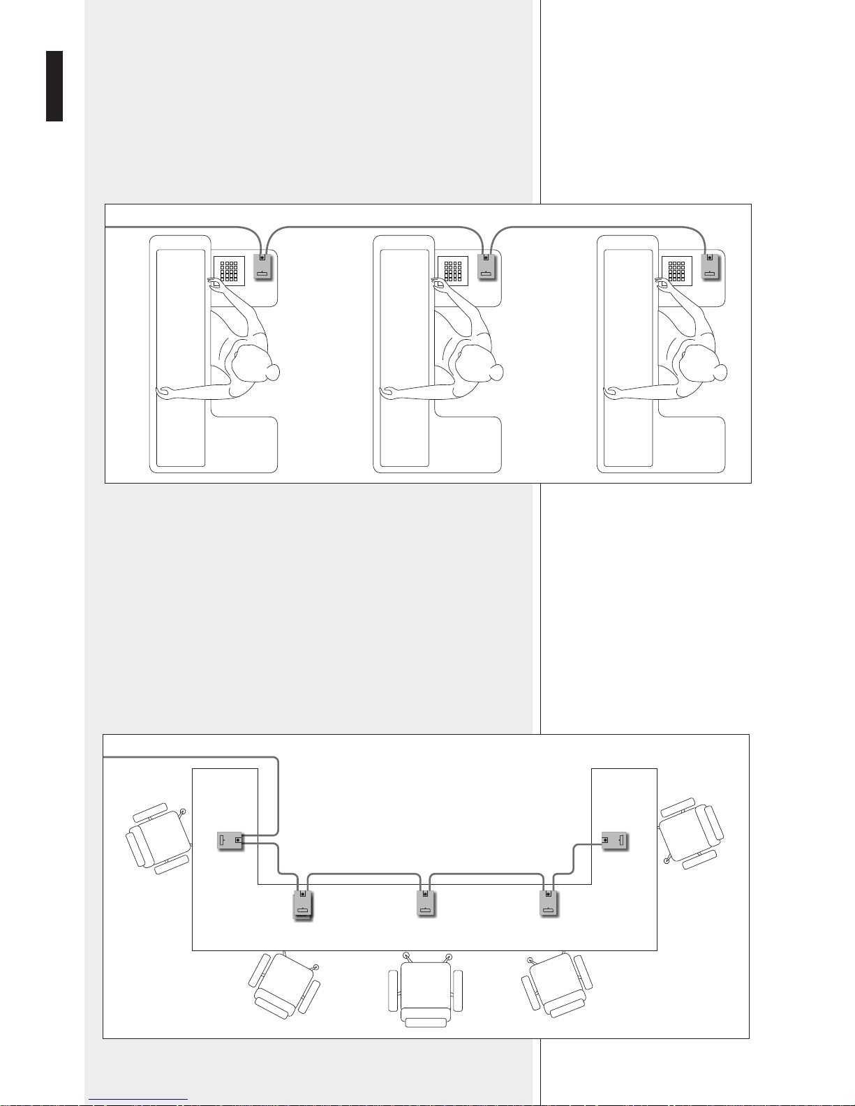
— CONFERENCE HALL
One BM 3022 for every delegate and one having priority for the chairman.
All paging microphones are linked in series (‘daisy-chain’) and operating in
mixing mode (but the chairman’s one with priority).
Dip-switch 2 and 3 settings:
- dip-switch no.2 (delegates’ microphones): OFF (no priority)
- dip-switch no.2 (chairman’s microphone): ON (with priority)
- dip-switch no.3: Mix (mixing mode)
PRIORITY: ON
Page 9

9
ENGLISH
REAR PANEL AND CONNECTIONS
1 Power Supply Input: input for the external 24 V dc - 100 mA
adapter (RCF AC AD2405).
The 24 V dc voltage (from the adapter) is also available on the pins 4 and
5 of the output RJ 45 socket to power the next (up to 3) BM 3022 paging
microphones.
2 RJ 45 Input: input for the CAT5 cable coming from the previous
BM 3022 paging microphone.
Pins:
1. audio signal (+, hot)
2. audio signal (–, cold)
3. relay contact
4. ground
5. power
6. relay contact
7. RS-485 (A)
8. RS-485 (B)
3 RJ 45 Output: output for the CAT5 cable to either the next BM 3022
or a mixer-amplifier input. Pins: see 2.
4 Chime Level: Trimmer to adjust (through a small screwdriver)
the chime level.
5 Output Level: Trimmer to adjust (through a small screwdriver)
the output audio signal level.
5 4
3 2 1
Page 10

10
ENGLISH
It is possible to link in series ('daisy-chain') up to 30 BM 3022 paging
microphones in a single line (the output of a paging microphone is sent to
the input of the next one).
The included adapter (RCF AC AD2405, 24 V dc) can power up to 4 BM
3022 paging microphones (note: the power supply is linked in parallel on RJ
connectors, pin 5: +, pin 4: –).
The RJ45 output of the last BM 3022 paging microphone shall be
connected to the amplifier through a custom cable (not included),
according to the following schematic.
The RJ45 input of the first BM 3022 paging microphone allows to connect a
generic stereo music (e.g. RCF MS 1033) that has an adjustable output level
(range -10 ÷ + 4 dBu).
See the following schematic.
Brown
Brown/ White
Green
Blue/ White
Blue
Green/ White
Orange
Orange/White
12345678
Green
Blue
Green/White
Orange
Orange/White
gnd
+
–
DRY CLOSING CONTACT
FOR PRIORITY
AUDIO SIGNAL
Brown
Brown/ White
Green
Blue/ White
Blue
Green/ White
Orange
Orange/White
12345678
L
R
RJ
15K
_
+
15K
STEREO
MUSIC
SOURCE
2 SHIELDED WIRES
RCA
RJ
AC AD2405
(max. 4 BM 3022)
24 V dc
AC AD2405
24 V dc
TALK TALKTALK TALKTALK TALK
max. 30
BM 3022
IN IN IN IN IN INOUT OUT OUT OUT OUT OUT
AMP.
CAT 5 CAT 5 CAT 5 CAT 5 CAT 5
4 3 2 1
Page 11

11
ENGLISH
6 TALK button: press to turn the microphone on (if the line is not
engaged).
If the dip-switch no.8 is set to OFF, the TALK button must be held down when
speaking (and released at the end).
If the dip-switch no.8 is set to ON, the TALK button operates in ‘SMART’
mode:
- If the TALK button is pressed and quickly released, the microphone will be
turned on / off (‘toggle’).
- If the TALK is pressed and held down, the microphone will stay open until
the TALK button release (even if it has been previously activated as ‘toggle’).
Read the instructions about dip-switches no.2 (priority), no.3 (mixing or
interlocking mode) and no.5 (VOX function) in the ‘Operation and internal
settings’ manual section.
7 Bi-colour LED
FRONT PANEL
COLOUR
Steady green
Steady red
Flashing red
INDICATION
The paging microphone is properly powered (24 V dc)
Activated microphone
Engaged line
6
7
TALK
Page 12

12
ENGLISH
SPECIFICATIONS
Paging microphone with electret capsule
200 Hz ÷ 7 kHz
> 72 dB (AGC: ON), > 82 dB (AGC: OFF)
< 0.65 % (AGC: ON)
– 10 ÷ + 4 dBu (245 mV ÷ 1.23 V)
@ 3.3 kΩ (balanced)
130 Ω
470 Ω
– 10 ÷ + 4 dBu (245 mV ÷ 1.23 V)
@ 3.3 kΩ (balanced)
47 kΩ
24 V dc, through included adapter
(RCF AC AD2405)
100 mA
100 mm (l), 48 mm (h), 159 mm (d)
(without gooseneck)
0.6 kg
Cable CAT5 FTP, 5 m
Cardioid
– 65 dB ± 3 dB (0 dB = 1 µbar @ 1 kHz)
2000 Ω ± 30% (@ 1 kHz)
50 Hz ÷ 16 kHz
Type
Frequency response
Signal / noise ratio
Distortion
Output level
Output impedance
Minimum load impedance
Input sensitivity
Input impedance
Power supply
Max. current (power supply)
Dimensions
Net weight
Included accessories
MIC. CAPSULE
Polar pattern
Sensitivity
Impedance
Frequency response
Page 13

Page 14

14
ITALIANO
AVVERTENZE PER
LA SICUREZZA
IMPORTANTE
IMPORTANTE
Prima di collegare ed utilizzare la base microfonica, leggere attentamente le istruzioni
contenute in questo manuale, il quale è da conservare per riferimenti futuri. Il presente
manuale costituisce parte integrante del prodotto e deve accompagnare quest’ultimo
anche nei passaggi di proprietà, per permettere al nuovo proprietario di conoscere le
modalità d’installazione e d’utilizzo e le avvertenze per la sicurezza.
L’installazione e l’utilizzo errati del prodotto esimono RCF S.p.A. da ogni responsabilità.
AVVERTENZE PER LA SICUREZZA
1. Tutte le avvertenze, in particolare quelle relative alla sicurezza, devono essere lette
con particolare attenzione, in quanto contengono importanti informazioni.
2. Prima di accendere le apparecchiature, assicurarsi che tutte le connessioni siano
corrette.
Non collegare / scollegare la base microfonica quando il sistema è acceso.
3. Accertarsi che il cavo della base microfonica non possa essere calpestato o
schiacciato da oggetti, al fine di salvaguardarne l’integrità.
4. Non immergere la base microfonica nell’acqua (od in altri liquidi), non lanciarla o
lasciarla cadere.
5. Non eseguire sulla base microfonica interventi / modifiche / riparazioni; contattare i
centri di assistenza autorizzati nel caso che non funzioni correttamente.
6. Nel caso che dalla base microfonica provengano stranamente odori anomali od
addirittura fumo, spegnere immediatamente il sistema audio, scollegarla e togliere
l’alimentazione.
7. RCF S.p.A. raccomanda vivamente che l’installazione del sistema audio sia eseguita
solamente da installatori professionali qualificati (oppure da ditte specializzate) in grado
di farla correttamente e certificarla in accordo con le normative vigenti.
Tutto il sistema audio dovrà essere in conformità con le norme e le leggi vigenti in
materia di impianti elettrici.
8. Vi sono numerosi fattori meccanici ed elettrici da considerare quando si installa
un sistema audio professionale (oltre a quelli prettamente acustici, come la pressione
sonora, gli angoli di copertura, la risposta in frequenza, ecc.).
9. Non puntare la base microfonica verso un diffusore vicino, onde evitare un possibile
innesco.
10. Perdita dell’udito
L’esposizione ad elevati livelli sonori può provocare la perdita permanente dell’udito.
Il livello di pressione acustica pericolosa per l’udito varia sensibilmente da persona
a persona e dipende dalla durata dell’esposizione. Per evitare un’esposizione
potenzialmente pericolosa ad elevati livelli di pressione acustica, è necessario che
chiunque sia sottoposto a tali livelli utilizzi delle adeguate protezioni; quando si
fa funzionare un trasduttore in grado di produrre elevati livelli sonori è necessario
indossare dei tappi per orecchie o delle cuffie protettive.
11. Per evitare che fenomeni induttivi diano luogo a ronzii, disturbi e compromettano
il buon funzionamento dell’impianto, il cavo della base microfonica non deve essere
canalizzato insieme ai conduttori dell’energia elettrica e/o alle linee dei diffusori acustici.
12. Collocare la base microfonica lontano da fiamme (o fonti di calore eccessivo).
13. Non usare solventi, alcool, benzina o altre sostanze volatili per la pulitura delle parti
esterne; usare un panno asciutto.
Page 15

15
ITALIANO
RCF S.P.A. VI RINGRAZIA PER L’ACQUISTO DI QUESTO PRODOTTO,
REALIZZATO IN MODO DA GARANTIRNE L’AFFIDABILITÀ E
PRESTAZIONI ELEVATE.
BM 3022 è una base microfonica preamplificata da tavolo con microfono ad
elettrete.
Il livello del suo segnale audio d’uscita (bilanciato e regolabile tramite trimmer),
ne permette il collegamento ad ingressi di tipo “linea” di mixer-amplificatori
anche a lunga distanza (fino ad 1 km) tramite cavo CAT5.
Ciascuna base microfonica è dotata di un controllo automatico del guadagno
(AGC), ovvero un compressore / limitatore che (se inserito) permette di
normalizzare il livello del segnale proveniente dal microfono a prescindere
dall’intensità della voce.
Fino 30 basi microfoniche BM 3022 possono essere collegate serialmente
(in un’unica linea) ed essere utilizzate in miscelazione (più microfoni accesi
contemporaneamente) od in interblocco (solo un microfono attivo alla volta).
Una o più basi microfoniche possono essere prioritarie, con la possibilità di
intervenire in qualsiasi momento disattivando provvisoriamente le altre basi
microfoniche.
Dopo l’attivazione di un microfono, l’annuncio può essere preceduto da un tono
di preavviso.
E’ incluso un alimentatore RCF AC AD2405 (24 V c.c.), utilizzabile per
l’alimentazione di massimo 4 basi microfoniche BM 3022.
DESCRIZIONE
FUNZIONAMENTO ED IMPOSTAZIONI ALL’INTERNO
Prima di procedere al collegamento, è necessario impostare i microinterruttori
interni (“dip-switch”) di ogni base microfonica BM 3022 secondo la modalità di
utilizzo prescelta.
Per accedere ai microinterruttori, occorre rimuovere il coperchio posteriore
svitando le 6 viti di fissaggio.
LOCAZIONE 6 VITI DEL
COPERCHIO POSTERIOREDIP-SWITCH
Page 16

16
ITALIANO
DIP-SWITCH nr. 1: AGC – Controllo automatico del guadagno
Compressore / limitatore che, se inserito, permette di normalizzare il livello del
segnale proveniente dal microfono a prescindere dall’intensità della voce.
Impostazione consigliata: ON.
DIP-SWITCH nr.2: Priority – Priorità
Priorità della base microfonica BM 3022 su tutte altre (non prioritarie) collegate
nella stessa linea.
Le basi microfoniche con priorità possono occupare il canale audio in qualsiasi
momento, disattivando provvisoriamente tutte le altre basi microfoniche non
prioritarie.
Nella modalità “interblocco” (dip-switch nr.3 impostato su “I/Lock”), solo una
base microfonica prioritaria può essere attivata (la prima in ordine cronologico).
DIP-SWITCH nr.3: Miscelazione (Mix) – Interblocco (I/Lock)
QuesTa imposTazione è necessaria Quando si ha una linea composTa da 2 o più Basi
microfoniche Bm 3022, le Quali devono TuTTe avere il dip-swiTch nr.3 posTo nella sTessa
posizione (“mix” oppure “i/lock”).
Miscelazione: in una linea composta da più basi microfoniche BM 3022,
il segnale di ciascuna (se attivata tramite il tasto TALK) è sempre posto in
miscelazione sul canale audio condiviso.
Interblocco: in una linea composta da più basi microfoniche BM 3022, solo
una può essere attivata (la prima in ordine cronologico); dopo l’attivazione, le
altre basi microfoniche avranno la segnalazione di linea occupata e dovranno
attendere (fino al disimpegno della linea).
le Basi microfoniche Bm 3022 avenTi la prioriTà (dip-swiTch nr.2 su on) cosTiTuiscono
un’eccezione e possono occupare il canale audio in Qualsiasi momenTo, disaTTivando
provvisoriamenTe TuTTe le alTre Basi microfoniche non prioriTarie.
nella modaliTà “inTerBlocco”, solo una Base microfonica prioriTaria può essere aTTivaTa
(la prima in ordine cronologico); TuTTe le alTre Basi microfoniche, prioriTarie o no, dovranno
aTTendere il disimpegno della linea.
AGC – Controllo automatico del guadagno
Priority – Priorità
Miscelazione / Interblocco
Chime – Tono di preavviso
VOX – Funzione VOX
VOX Level – Sensibilità della funzione VOX
VOX Release – Tempo di rilascio della funzione VOX
SMART PTT – Funzionamento bistabile tasto TALK
ON: inserito
ON: priorità attivata
I/Lock: interblocco
ON: abilitato
ON: abilitata
Low: bassa sensibilità
(soglia di intervento alta)
Long: lungo (30 s)
ON: abilitato
OFF: disinserito
OFF: priorità disattivata
Mix: miscelazione
OFF: disabilitato
OFF: disabilitata
Hi: alta sensibilità
(soglia di intervento bassa)
(Short): breve (3 s)
OFF: disabilitato
1
2
3
4
5
6
7
8
Page 17

17
ITALIANO
DIP-SWITCH nr.4: Chime – Tono di preavviso
Se abilitato, all’attivazione di una base microfonica BM 3022 (pressione del
tasto TALK) è inviato un tono di preavviso (che precede l’annuncio microfonico).
Il livello del tono di preavviso è regolabile tramite l’apposito trimmer “Chime
Level”.
DIP-SWITCH nr.5: Funzione VOX
Se la funzione VOX è abilitata, dopo aver premuto il tasto TALK, il microfono
è aperto automaticamente solo se la sua capsula rileva un suono con intensità superiore alla soglia prefissata ed è richiuso (dopo il tempo di rilascio
“VOX Release”, vedi dip-switch nr.7) non appena l’intensità del suono ritorna
sotto la soglia.
la funzione vox può essere uTile per eviTare possiBili reTroazioni acusTiche indesideraTe
(effeTTo “larsen”, “feedBack”), in QuanTo i microfoni sono chiusi Quando non
uTilizzaTi.
DIP-SWITCH nr.6: VOX Level – Sensibilità della funzione VOX
Consente di impostare la sensibilità della funzione VOX tra 2 livelli:
- Hi: sensibilità alta (la soglia di intervento è bassa), il microfono si attiva con
voce bassa;
- Low: sensibilità bassa (la soglia di intervento è alta), il microfono si attiva
con voce alta.
DIP-SWITCH nr.7: VOX Release – Tempo di rilascio della funzione VOX
Impostazione del tempo di rilascio della funzione VOX, ovvero il tempo che
intercorre tra l’assenza di un suono con intensità superiore alla soglia prefissata e la chiusura automatica del microfono.
Le opzioni sono:
- (Short): tempo breve (3 s), ideale per l’utilizzo in conferenze, dove il
microfono si chiude subito al termine dell’intervento dell’oratore;
- Long: tempo lungo (30 s), dopo l’attivazione il microfono rimane aperto in
assenza di segnale per almeno 30 s, successivamente la base microfonica è
automaticamente disattivata (come se si premesse di nuovo il tasto TALK);
questa modalità è preferibile se la base microfonica è usata prevalentemente
per annunci.
DIP-SWITCH nr.8: SMART PTT – Funzionamento bistabile tasto TALK
Il tasto TALK attiva il microfono (permettendo la diffusione dell’annuncio).
Se questo dip-switch è impostato su OFF, il tasto TALK deve essere mantenuto premuto per tutta la durata dell’intervento / annuncio vocale (e rilasciato
al termine).
Se questo dip-switch è impostato su ON, il tasto TALK è posto in “modalità
intelligente” (“SMART”), permettendo anche il funzionamento bistabile:
- se il tasto TALK è premuto e rilasciato velocemente, si attiva o disattiva il
microfono in modo stabile;
- se il tasto TALK è mantenuto premuto, si attiva il microfono fino al rilascio
dello stesso (anche nel caso che sia stato precedentemente attivato in modo
stabile).
Page 18

18
ITALIANO
ESEMPI DI UTILIZZO
— SUPERMERCATO
È prevista una base microfonica BM 3022 per ogni cassa.
Le basi microfoniche sono collegate in cascata ed interbloccate tra loro.
Impostazioni dei dip-switch 2 e 3 su tutte le base microfoniche:
- dip-switch nr.2: OFF (priorità disattivata)
- dip-switch nr.3: I/Lock (interblocco)
Come opzione, è possibile aggiungere una base microfonica BM 3022
prioritaria (dip-switch nr.2 impostato su ON) per l’ufficio della direzione.
— SALA CONSILIARE O PER CONFERENZE
È prevista una base microfonica BM 3022 per ogni consigliere / delegato ed
una prioritaria per il presidente.
Le basi microfoniche sono collegate in cascata e poste in miscelazione (ad
eccezione di quella prioritaria del presidente).
Impostazioni dei dip-switch 2 e 3:
- dip-switch nr.2 (consigliere/ delegato): OFF (priorità disattivata)
- dip-switch nr.2 (presidente): ON (priorità attivata)
- dip-switch nr.3: Mix (miscelazione)
PRIORITY: ON
Page 19

19
ITALIANO
PANNELLO POSTERIORE E COLLEGAMENTO
1 Power Supply Input: ingresso per alimentatore esterno 24 V c.c. -
100 mA (RCF AC AD2405).
La tensione 24 V c.c. è riportata sui contatti 4 e 5 del connettore RJ 45
d’uscita 3 per l’alimentazione anche delle (eventuali) successive 3 basi
microfoniche BM 3022.
2 RJ 45 Input: ingresso con connettore RJ 45 per il cavo (di tipo CAT5)
proveniente dalla base microfonica BM 3022 precedente.
Contatti:
1. segnale audio (+)
2. segnale audio (–)
3. contatto relè
4. massa
5. alimentazione
6. contatto relè
7. Connessione seriale RS-485 (A)
8. Connessione seriale RS-485 (B)
3 RJ 45 Output: uscita con connettore RJ 45 per il collegamento (tramite
cavo CAT5) della base microfonica BM 3022 successiva oppure ad un mixeramplificatore. Contatti: vedere il punto 2.
4 Chime Level: Trimmer per la regolazione (tramite un piccolo cacciavite)
del livello del tono di preavviso.
5 Output Level: Trimmer per la regolazione (tramite un piccolo
cacciavite) del livello d’uscita del segnale audio.
5 4
3 2 1
Page 20

20
ITALIANO
L’uscita RJ45 dell’ultima base microfonica BM 3022 sarà collegata
all’amplificatore tramite un cavo adatto (non incluso), secondo lo
schema seguente.
il relè inTerno è ecciTaTo duranTe l’aTTivazione del microfono; i sui conTaTTi possono
essere uTilizzaTi per oTTenere la prioriTà nel mixer-amplificaTore. in una linea con più
Basi microfoniche, TuTTi i conTaTTi dei relè sono collegaTi in parallelo (TramiTe conTaTTi
3 e 6 dei conneTTori rJ 45).
All’ingresso RJ45 della prima base microfonica BM 3022, è possibile collegare
una sorgente musicale (stereo) generica (ad esempio RCF MS 1033) che
abbia un livello d’uscita controllabile e compreso tra –10 e + 4 dBu; vedere
lo schema seguente.
È possibile creare un’unica linea composta da massimo 30 basi microfoniche
BM 3022 collegate in serie (l’uscita OUT di una base microfonica è riportata
all’ingresso IN di quella successiva).
Occorre collegare un alimentatore (fornito a corredo) RCF AC AD2405 (24
V c.c.) per ogni gruppo composto da massimo 4 basi microfoniche BM 3022
(nota: l’alimentazione è riportata in parallelo sui connettori RJ, contatto 5: +,
contatto 4: –).
Marrone
Biancomarrone
Verde
Biancoblù
Blu
Biancoverde
Arancio
Biancoarancio
12345678
L
R
RJ
15K
_
+
15K
SORGENTE
MUSICALE
STEREO
PIATTINA SCHERMATA A 2 POLI
RCA
Marrone
Biancomarrone
Verde
Biancoblù
Blu
Biancoverde
Arancio
Biancoarancio
12345678
Verde
Blu
Biancoverde
Arancio
Biancoarancio
Massa
+
–
CONTATTO PULITO (chiusura)
PER PRIORITÀ
SEGNALE
AUDIO
RJ
AC AD2405
(max. 4 BM 3022)
24 V dc
AC AD2405
24 V dc
TALK TALKTALK TALKTALK TALK
max. 30
BM 3022
IN IN IN IN IN INOUT OUT OUT OUT OUT OUT
AMP.
CAT 5 CAT 5 CAT 5 CAT 5 CAT 5
4 3 2 1
Page 21

21
ITALIANO
6 Tasto TALK: premere per attivare il microfono (se la linea non è già
occupata).
Se il dip-switch nr.8 è impostato su OFF, il tasto TALK deve essere mantenuto
premuto per tutta la durata dell’intervento / annuncio vocale (e rilasciato
al termine); se è invece impostato su ON, il tasto TALK è posto in “modalità
intelligente” (“SMART”), permettendo anche il funzionamento bistabile:
- se il tasto TALK è premuto e rilasciato velocemente, si attiva o disattiva il
microfono in modo stabile;
- se il tasto TALK è mantenuto premuto, si attiva il microfono fino al rilascio
dello stesso (anche nel caso che sia stato precedentemente attivato in modo
stabile).
Leggere le descrizioni dei dip-switch nr.2 (priorità), nr.3 (miscelazione o
interblocco) e nr.5 (funzione VOX) alla sezione del manuale “Funzionamento
ed impostazioni all’interno”.
7 LED di segnalazione bicolore
PANNELLO FRONTALE
COLORE
Verde fisso
Rosso fisso
Rosso lampeggiante
SEGNALAZIONE
Base microfonica alimentata correttamente (24 V c.c.)
Microfono attivato
Linea occupata
6
7
TALK
Page 22

22
ITALIANO
DATI TECNICI
Base microfonica da tavolo
con microfono ad elettrete
200 Hz ÷ 7 kHz
> 72 dB (AGC: ON), > 82 dB (AGC: OFF)
< 0,65 % (AGC: ON)
– 10 ÷ + 4 dBu (245 mV ÷ 1,23 V)
@ 3,3 kΩ (uscita bilanciata)
130 Ω
470 Ω
– 10 ÷ + 4 dBu (245 mV ÷ 1,23 V)
@ 3,3 kΩ (uscita bilanciata)
47 kΩ
24 V c.c. tramite alimentatore
fornito a corredo RCF AC AD2405
100 mA
100 mm (l), 48 mm (h), 159 mm (p)
(senza braccio flessibile)
0,6 kg
Cavo CAT5 FTP, 5 m
0,5 A
24 V (c.c.)
Cardioide
– 65 dB ± 3 dB (0 dB = 1 µbar @ 1 kHz)
2000 Ω ± 30% (@ 1 kHz)
50 Hz ÷ 16 kHz
Tipo
Risposta in frequenza
Rapporto segnale / rumore
Distorsione
Livello d’uscita
Impedenza d’uscita
Minima impedenza di carico
Sensibilità d’ingresso
Impedenza d’ingresso
Alimentazione
Assorbimento massimo
Dimensioni
Peso netto
Accessori a corredo
CONTATTI DEL RELÈ INTERNO
Portata massima
Max. tensione applicabile
CAPSULA MICROFONICA
Direttività
Sensibilità
Impedenza
Risposta in frequenza
Page 23

Page 24

103 07 279 / RevB
www.rcfaudio.com
HEADQUARTERS:
RCF S.p.A. Italy
tel. +39 0522 274 411
e-mail: info@rcf.it
RCF UK
tel. 0844 745 1234
Int. +44 870 626 3142
e-mail: info@rcfaudio.co.uk
RCF France
tel. +33 1 49 01 02 31
e-mail: france@rcf.it
RCF Germany
tel. +49 2203 925370
e-mail: germany@rcf.it
RCF Spain
tel. +34 91 817 42 66
e-mail: info@rcfaudio.es
RCF Belgium
tel. +32 (0) 3 - 3268104
e-mail: belgium@rcf.it
RCF USA Inc.
tel. +1 (603) 926-4604
e-mail: info@rcf-usa.com
 Loading...