

Page 1
Communications Systems
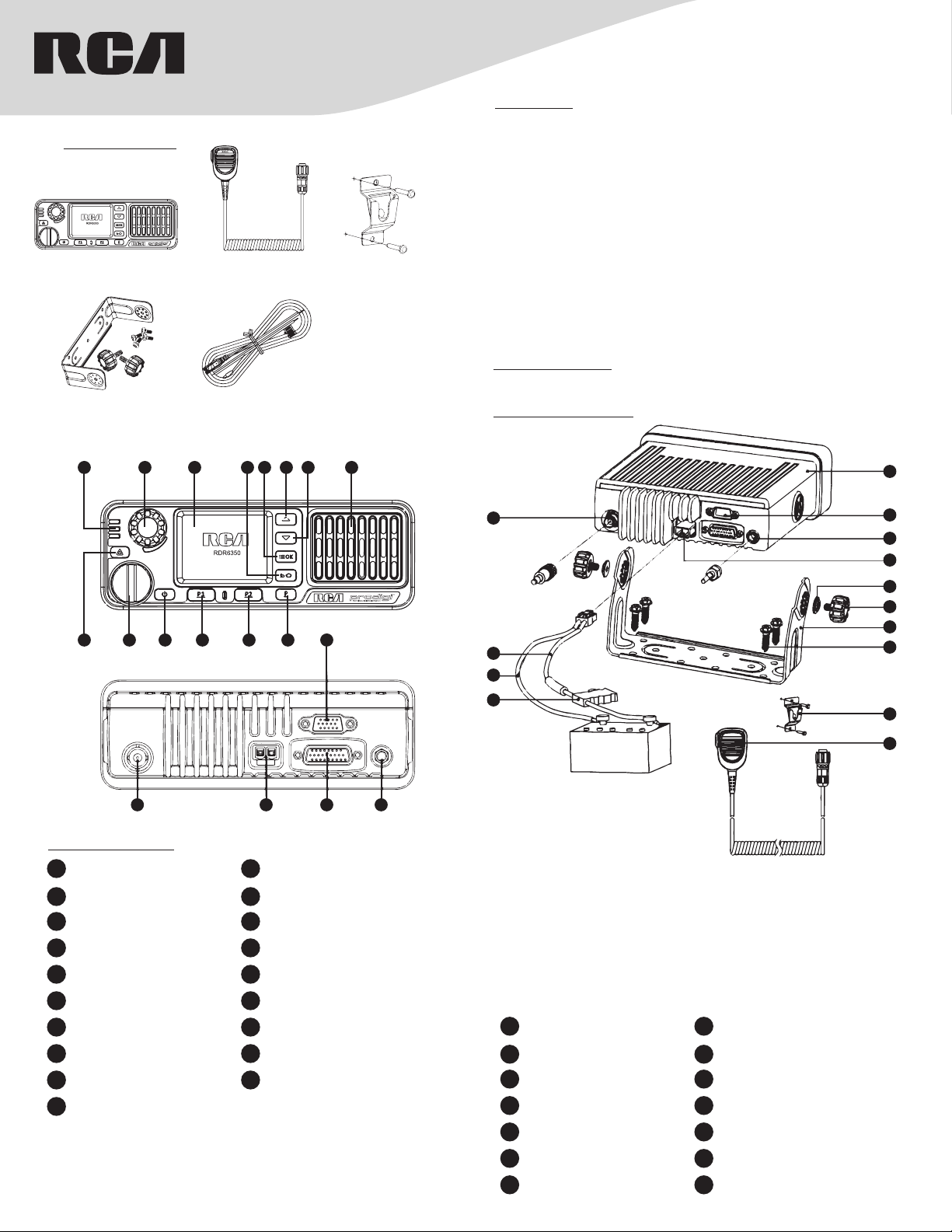
s Included:
What’
RDR6350U
Mobile R
adio
RDR6350U
DC Power Cable
RDR6350U Mobile
Digital R
RDR6350U
Mobile Mic
RDR6350U
DC Power Cable
adio
RDR6350U
Mic Hanger
QUICK S
TART GUIDE
Installation:
Read the following precautions before installing the mobile terminal:
• The radio operates with cathode-grounded power supply of 13.6V ± 15%
only. Please check polarity and voltage of the power supply on the vehicle
before you install the radio.
• Please check how long the screws will extend from the bot-tom surface of
the radio, before you install the radio. Drill the mounting hole cautiously to
avoid damage to the vehicle wiring and other parts.
• Please connect RCA supplied antenna and power cord to the radio, before
you install it in the bracket. And make sure the antenna and power cord is
dedicated for RCA digital radios to prevent injuries to passengers.
• Set the mobile terminal in a location convenient on the front panel for easy
operation.
• Please make sure there’s sufficient space at back of the radio for wiring.
• When the fuse for DC power cord needs replacement, it must be replaced
by a fuse with the same specification.
Installation Tools:
Electric Drill, Philips Head Screwdriver, and Hex Socket Sleeve
Installation Diagram:
1
9 10 11 12 13 14 15
2 3 4 5 6 7 8
16 17 18 19
Prodcut Overview:
V
1 LED Indicator 2
3 LCD Display 4 Option / Back / Home Button
5 Menu / Enter Button 6 Up Button
7 Down Button 8 Speaker
9 Emergency Call Button 10 Handheld Microphone Interface
Power On / O / On-Hook
11
Button
13 Cancel / P2 Button 14
15 Accessories Interface 16 RF Antenna Base
17 Power Interface 18 Accessories Interface
Positioning Module Antenna
19
Interface
olume Control / Channel
Selector Knob
12 Enter / P1 Key
Power Level / Lock / Unlock
Button
1
11
12
13
14
A. Install the brack
B. Connect the accessories such as the radio antenna and power cord to the
mobile 1.
C. Slide the mobile radio 1 into the mounting bracket 7 and fix it with cross
screw 6.
D. Install the microphone hanger 9 in a location where it’s easy to reach the
microphone.
E. Plug the handheld microphone 10 into the microphone jack on the front
panel of mobile radio 1 and place it on the hanger when not in use.
1 Mobile Radio 2 Accessory Interface
Position Module Antenna
3
Interface
Hardware Bracket Knob
5
Underlay
7 U-Shaped Bracket 8 M6 Self-tapping Cross Screw
Handheld Microphone
9
Hanger
11 RF Antenna Base 12 Red Power Line
et 7 with cross screw 8 in a proper position.
4 Power Supply Socket
6 Hardware Bracket Knob
10 Handheld Microphone
2
3
4
5
6
7
8
9
10
13 Black Power Line 14 Fuse
Page 2
Basic Operations
T
urning on/o radio
Short press [Power On / O / On-hook] button to tum on the radio, LCD
displays power-up LOGO, and then enter the standby screen, and then long
press [Power On/ O/ On-hook] button to shutdown.
Note: If a fault occurs and the radio does not turn o, you can press and hold
the [Power On / O/ On-hook] button for more than 1 O seconds with the
forced shutdown and restart it.
Knob Switch Mode
Short press the knob ,to switch the two modes between volume and channel/
group.
Radio Mode
The mobile terminal supports conventional and trunking mode, switching as
below:
1. Press [Option/ Back/ Home] button to bring up the option menu;
2. Press [Up]/ [Down] button to select ‘Radio mode’ and press [Menu / Enter]
button to enter the list of radio mode;
3. Press [Up]/ [Down] button to select ‘Conventional’ or ‘Trunking’ mode,
press [Menu / Enter] button to switch modes.
Note: In conventional mode the radio can communicate directly or via
repeater inter-mmmunicate; in trunking mode, the mobile terminal is
connected by the base station, to realize the fuction of real-time dispatchment.
Adjust the volume
When the Volume Control I Channel Selector knob operates in volume
adjustment mode, rotate the knob clockwise to increase the call volume, or
counterclockwise to decrease volume.
Adjusting the Power Level
Press [Power Level / Lock / Unlock] button to change the transmitting power
level to ‘High/ Mid/ low’, and also the icon of the power level will be changed
in the main menu.
Lock and Unlock
Long press [Power Level / Lock / Unlock] button can activating the keylock
function, in case of wrong operation. Deactivate the keylock by long.
Switching Channel / Group
When in the channel/ group switching mode, turn the knob to select channel/
group.
In addition you can also switch the channel/group in the menu:
1. Press [Option/ Back/ Home] button to go to the ‘Option’ menu.
2. Press [Up / Down] button to select ‘Channel Management I Group
Management’, press [Enter] to enter the channel / group folder list.
3. Press [Up]/ [Down] button to select the channel I group folder, press
[Enter] to enter the channel / group list.
4. Press [Up]/ [Down] button to select the channel/ group, press [Enter]
button to switch channel / group.
Note:
• ‘Channel Management’ and ‘Group Management’ are folders set up for
classified management of channels and groups in conventional mode and
trunking mode
This mobile terminal supports up to 64 channels / group folders, each folder
•
contains up to 100 channels / groups, and please set it up via the dealer
.
.
Call
Individual Call
Initiate the Individual Call
1. Input a individual call number you would lik
with a keypad , or enter ‘Phonebook’ / ‘Call Log’ / ‘Messages’, to select the
Contact/ Messages;
2. Hold down the [PTT] button on the handheld microphone to transmit a
individual call to the selected ccntact or message ccntact.
Receive and Call Back
1. When the [PTT] button is idle ,without any actions of buttons ,the mobile
radio could receive call.
2. You can hold down [PTT] button to call back after the calling party finish
talking.
Group Call
The groups are preset by the dealer, operating method in ccnventional and
trunking modes is the same.
Initiate Group Call
1. At standby screen, short press [Volume Control / Channel Selector]
button, then rotate to select channel / group that willing to call.
2. Press [Enter] button to ccnfirm the selected channel / group, or wait for it
ccnfirm automatically.
3. Hold down [PTT] button on handheld microphone to initiate group call.
e to call using the mircophone
Receive and Call Back
1. When [PTT] button is idle ,without any actions of buttons ,the
mobile radio cculd receive call.
2. You can hold down [PTT] button to call back after the calling
party finish talking.
Care and Cleaning
To guarantee optimal performance as well as a long service life of
your radio, please follow the tips below.
Radio Care
Keep the radio far away from substances that can corrode the
electronic circuit.
Radio Cleaning
Clean up the dust and fine particles on the radio surface with a clean
and dry lint-free cloth or a brush regularly.
Use neutral cleanser and a non-woven fabric to clean the keys,
control knobs and microphone after long-time use. Do not use
chemical preparations such as stain removers, alcohol, sprays or oil
preparations, so as to avoid surface case damage. Make sure that
the radio is completely dry before use.
NOTE: Turn o the radio before cleaning.
LED indicator
LED Indication R
LED Glows Red Transmitting
LED Glows Green Receiving
LED Glows Green &
Flashing Slowly
S
TATUS INDICATION IN RADIO
LCD Icon
Icon Name Icon Radio Status
RSSI
Message Icons
Working Mode Icons
P
ower Level Icons
Profiles Icon
Accessory Icon
Handheld Mic Icon
tatus Icon
Call S
Channel / Group
Selection Icon
Encryption Icon
P
ositioning Icon
adio Status
Standby
No Signal
More bars indicate better signal strength
New message/unread message
x is full
Inbo
Indicates in trunking mode
Indicates in conventional mode
Indicates L
Indicates Mid-P
Indicates High-P
Indicates the silent mode is enabled
Indicates the standard mode is enabled
Indicates the custom mode is enabled
Accessory is plugged in
Handheld Mic is plugged in
Indicates currently talking
Indicates missed calls
Indicates in-channel selection mode
Encryption ON
P
positioning data is received
P
positioning data is received
ow-Power transmission
ower transmission
ower transmission
ositioning feature is active and valid
ositioning feature is active but no valid
Page 3

Warning!
Any C
hanges or modifications not expressly approved by the party responsible for compliance could void the
user's authority to operate the eq uipment.
This device complies with part 15 o f the F CC R ule s.O per ati on is subje ct to the follo wing two co nditions: ( 1) This
device may not cause harmful interference, and (2) this device must accept any interference received, including
interference that may cause undesired operation.
Note: This equipment has been tested and found to comply with the limits for a Class B digital device, pursuant t o
part 15 of the FCC Rules. These limits are designed to provide reasonable protection against harmful interference
in a residential installation. This eq uipment generates, uses and can radiate radio frequency energy and, if not
installed and used in accordance with the instructions, may cause harmful i nterference to radio communications.
However, there is no guarantee that interfere nce will not occur in a particular installatio n. If this equipment does
cause harmful interference to radio or television reception, which can be determined by turning the equipment off
and on, the user is encouraged to try to correct the interference by one or more of the following measures:
—Reorient or relocate the receiving antenna.
—Increase the separation between the equipment and receiver.
—Connect the equipment into a n outlet on a circuit different fro m that to which the receiver is connected.
—Consult the dealer or an experienced radio/TV technician for help.
This equipme
controlled environment .This equipmentVDQWHQQD should be installed and operated
ZLWKDminimum distance of 8 0 cm between the antenna & body.
RF expos
To control your exposure and ensure compliance with the occupational/controlled environment exposure
limits always adhere to the following procedures.
Guidelines:
Do not remove the RF Exposure Label from the device.
User awareness instructions should accompany device when transferred to other users.
Do not use this device if the operational requirements described herein are not met.
Operating Instructions:
Transmit no more than the rated duty factor of 50% of the time. To transmit(talk), push the
Push-To-Talk(PTT)button. To receive calls, release the PTT button. Transmitting 50% of the
time, or less, is important because this radio generates measurable RF energy exposure only when
transmitting(in terms of measuring for standards compliance).
Use only manufacturer's name approved supplied or replacement antennas, and accessories.
Use of non-manufacturer-name approved antennas, and accessories may exceed the RF
exposure guidelines. The max antenna gain allowed is 5.5 dBi.
nt complies with FCC,& radiation exposure limits set forth for an
ure stateme
nt
Page 4

ISEDC Compliance statement
This device complies with Industry C
Operation is subject to the following two conditions:
anada licence-exempt RSS standard(s).
(1) this device may not cause interference, and
(2) this device must accept any interference, including interference that may
cause undesired operation of the device.
Le présent appareil est conforme aux CNR d'Industrie Canada applicables aux
appareils radio exempts de licence. L'exploitation est autorisée aux deux conditions
suivantes : (1) l'appareil ne
doit pas produire de brouillage, et (2) l'utilisateur de l'appareil doit accepter tout
brouillage radioélectrique subi, même si le brouillage est susceptible d' en
Cet équipemen
environnementcontrôlé.Cetéquipementdoit êtreinstallé et utilisé avec une distance minimale
de80cmentreleradiateuretvotrecorps.
t est conforme aux limites d’exposition de rayonnement établies pour un
ISEDC
 Loading...