

Page 1
Communications Systems
RDR4300 Series
Digital Radios
QUICK START GUIDE
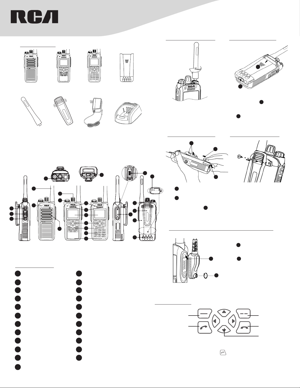
What’s Included:
MIC
RDR4320
Handheld Radio
Antenna
ANH4300U - UHF
ANH4300V - VHF
4
RDR4350
Handheld Radio
BC4300
Belt Clip
RDR4380
Handheld Radio
PS4301
Power Supply
16
B4323LI
Li-Ion Battery
(2550 mAh)
CH4301
Desktop Rapid
Charger
Attaching the Antenna:
Attaching the Battery:
1
2
1. While laying flat, put the battery
1. Turn the antenna clockwise to
attach it.
Note: To remove the antenna,
rotate it counter-clockwise.
Removing the Battery:
1
2
22
23
3
horizontally push to the top along
the aluminum slot.
2
2. As shown, up the battery latch
forward until a click is heard.
Attaching the Belt Clip:
into the radio as shown,
1
5
7
8
1
2
3
6
13
RDR4320 RDR4350 RDR4380
9
10
11
12
13
14
15
Prodcut Overview
1 P1 Key (hot key) 2 PTT Key (transmit key)
3 P2 Key (hot key) 4 Emergency Call Key
5 Antenna 6 LED Indicator
7 Channel Knob 8 Radio On-O/ Volume Knob
9 Earpiece
LCD Display (RDR4350/RDR4380
11
only)
(RDR4350/RDR4380 only)
13 Speaker 14
Duplex Microphone
15
RDR4380 only)
(RDR4350/
17 Accessory Jack Cover 18 Strap hole
19 Belt Clip 20 Battery
21 Battery Pole Piece 22 Accessory Jack
Micro SD Encryption Card
23
Cover
Simplex Microphone
10
RDR4380 only)
Function Keypad (RDR4350/RDR4380
12
only)
Numeric Keypad
only)
(RDR4350/RDR4380
16 Battery Latch
17
(RDR4350/
1
1. As shown, hold the radio like
this.
2
2. As shown, push up the battery
18
19
20
latch with another hand.
3. Slide the battery as arrow
3
direction shown.
1. Rotate the screws counterclockwise to remove them.
2. Align the screw holes on the
belt clip with those on the
radio’s body, and then tighten
the screws clockwise.
Note: To remove the belt clip,
loosen the screws.
Attaching audio accessory / programming cable:
21
1
Function Keypad
(RDR4350 / RDR4380 models)
Function/Enter key
Receive/Call key
Programmable Keys
[P1] key, [P2] key, four direction keys, key, can be set as function or
menu shortcut keys by your RCA dealer. The default state of [P1] and [P2]
shortcuts are for high-low power switching. You only need to press the
corresponding shortcut key to quickly access the needed menu or function.
1. Open the accessory jack cover.
1
As shown, align the plug
with the accessory jack, then
connet it.
2
2. As shown, tighten the screw
clockwise on the plug.
Note: To remove accessories,
loosen the screw counter-
2
clockwise.
Back/Option key
Hangup key
Direction key
Page 2
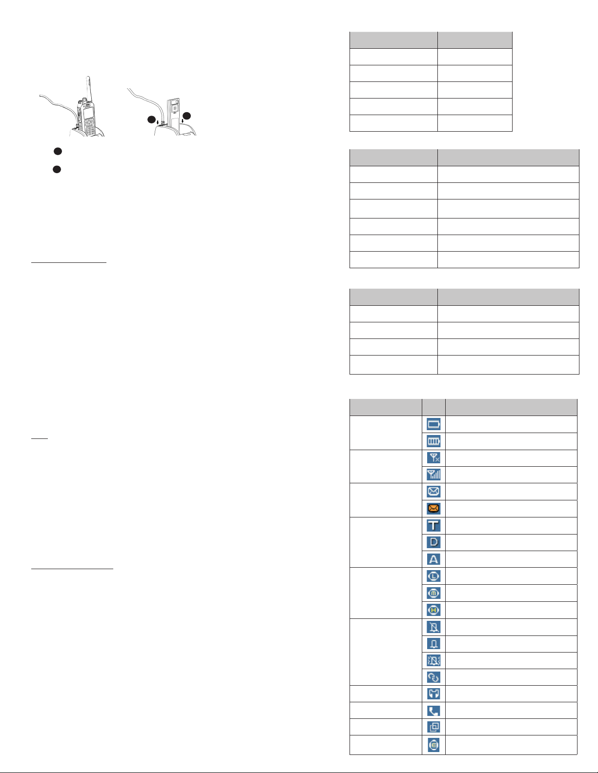
Charging the Battery
Charging Operation Steps
Use only the charger and batter y specified by
RCA Communications Systems. Charger LED
can indicate the changing progress.
LED indicator and charging status in charger
LED Indication Charging Status
LED Flashes Red Slowly Standby (no load)
LED Glows Red Charging
LED Glows Orange 85% Charged
1
1
1. As shown, Connect the power adapter to AC power
2
socket and the jack at the back of the charger.
2
2. As shown, inser t battery or radio with battery in
the charger, and make sure there is good contact
between battery and charging terminals.
3. The charging process starts when LED glows red.
4. LED glows green to indicate that charging is complete.
NOTE: The standard 2250mAh battery charging normally
takes about 4 hours, for optimal batter y performance. Initial
charging for new batter y should take up to 5 hours.
Basic Operations
Turning on/o radio
Rotate the Radio On-O/Volume knob clockwise / counter-clockwise until a
click is heard to turn on/o the radio.
Adjust the volume
After turning the radio on, rotate the Radio On-O/Volume knob clockwise to
increase the volume or counter-clockwise to decrease the volume.
Selecting a channel
According the series number on the Channel Knob to rotate and select the
desired channel. While rotating the knob, there is an automated channel
number Voice prompt.
Mode Switch
Through Channel Selector knob. Each channel of the radio can be set as
analog channel or digital channel by dealer. The user can set up through CPS
software.
Call
Group Call
Talk group can be set by dealer in advance the operation methods are the
same under DMO mode and TMO mode.
• Transmitting a group call
1. Select the desired talk group through Channel Knob.
2. Hold down [PTT] key to transmitt a group call.
• Receiving and replying a group call
You can receive the group call without any key operation. If reply is needed,
please hold down [PTT] key after the speech of the other side and then
speak to microphone.
Care and Cleaning
To guarantee optimal performance as well as a long service life of your radio,
please follow the tips below.
Radio Care
Keep the radio far away from substances that can corrode the electronic
circuit.
Do not hold the radio by its antenna or headset cable directly to prevent
damage to its normal use.
Attach the accessory jack cover whtn the radio is not in use.
Radio Cleaning
Clean up the dust and fine particles on the radio surface and charging piece
with a clean and dry lint-free cloth or a brush regularly.
Use neutral cleanser and a non-woven fabric to clean the keys, control knobs
and front case after long-time use. Do not use chemical preparations such as
stain removers, alcohol, sprays or oil preparations, so as to avoid surface case
damage. Make sure that the radio is completely dry before use.
NOTE; Turn o the radio and remove tha battery before cleaning.
LED Glows Green Fully Charged
LED Flashes Red Rapidly Error
Radio LED indicator
LED Indication Radio Status
LED Glows Red Transmitting the call
LED Glows Green Receiving the call
LED Glows Red On Both
Sides
LED Flashes Red Slowly Low Battery Power
LED Flashes Green Slowly Channel is Idle
LED Glows Orange Channel is Busy
Battery indicator
Battery Usage Status Indicator Light Status
Power > 40% Battery indicator light shut down
10% < Power < 40% Green light flash
Power < 10% Red light flash
No Power
STATUS INDICATION IN RADIO (RDR4350 / RDR4380 models)
LCD Icon
Icon Name Icon Radio Status
Battery Strength Icons
RSSI
Message Icons
Operation Mode Icons
Power Icons
Profiles Icon
Audio Accessories Audio accessory has been connected
Call Status Icon
Group Selection Icon
Encryption Icon
Phone Call
LED indicator light and battery indicator light
shut down
Low battery power
More bars indicate more battery power
No Signal
More bars indicate better signal strength
New message/unread message
Inbox is full
TMO mode
DMO mode
Analog mode
Transmit with lower power
Transmit with middle power
Transmit with high power
Silent mode
Ring
Vibrate
Custom
On the phone
Select talk group
Encryption ON
Page 3

FCC STATEMENT
This device complies with Part 15 of the FCC Rules. Operation is subject to the following
two conditions:
(1) This device may not cause harmful interference, and
(2) this device must accept any interference received, including interference that may
cause undesired operation.
NOTE 1: This equipment has been tested and found to comply with the limits for a Class
B digital device, pursuant to part 15 of the FCC Rules. These limits are designed to
provide reasonable protection against harmful interference in a residential installation.
This equipment generates, uses and can radiate radio frequency energy and, if not
installed and used in accordance with the instructions, may cause harmful interference to
radio communications. However, there is no guarantee that interference will not occur in
a particular installation. If this equipment does cause harmful interference to radio or
television reception, which can be determined by turning the equipment off and on, the
user is encouraged to try to correct the interference by one or more of the following
measures:
- Reorient or relocate the receiving antenna.
- Increase the separation between the equipment and receiver.
-Connect the equipment into an outlet on a circuit different from that to which the
receiver is connected.
-Consult the dealer or an experienced radio/TV technician for help.
NOTE 2: Any changes or modifications to this unit not expressly approved by the party
responsible for compliance could void the user's authority to operate the equipment.
Page 4

RF Exposure Compliance and Control Guidelines and Operating Instructions
To control your exposure and ensure compliance with the occupational/controlled environment
exposure limits always adhere to the following procedures.
Guidelines:
• Do not remove the RF Exposure Label from the device.
• User awareness instructions should accompany device when transferred to other users.
• Do not use this device if the operational requirements described herein are not met.
Operating Instructions:
• Transmit no more than the rated duty factor of 50% of the time. To transmit (talk), push the
Push-To-Talk (PTT) button. To receive calls, release the PTT button. Transmitting 50 % of the
time, or less, is important because this radio generates measurable RF energy exposure only when
transmitting (in terms of measuring for standards compliance).
• Hold the radio in a vertical position in front of face with the microphone (and the other parts of
the radio, including the antenna) at least one inch (2.5 cm) away from the nose. Keeping the
radio at the proper distance is important because RF exposures decrease with distance from the
antenna. Antenna should be kept away from eyes.
• When worn on the body, always place the radio in a
RCA
’s approved clip, holder, holster, case, or
body harness for this product. Using approved body-worn accessories is important because the use
of
’s or other manufacturer ’s non-approved accessories may result in exposure levels, which
RCA
exceed the FCC’s occupational/controlled environment RF exposure limits.
• If you are not using a body-worn accessory and are not using the radio in the intended use
position in front of the face, then ensure the antenna and the radio are kept at least 2.5 cm (one
inch) from the body when transmitting. Keeping the radio at the proper distance is important
because RF exposures decrease with increasing distance from the antenna.
• Use only manufacturer’s name approved supplied or replacement antennas, batteries, and
accessories. Use of non-manufacturer-name approved antennas, batteries, and accessories may
exceed the FCC RF exposure guidelines.
•For a list of
RCA
’s approved accessories (see the user manual), or(The manufacturer should
include the appropriate bracketed item{s} in the manual.)
’s approved accessories (see the user manual)
• For a list of
RCA
 Loading...