

Page 1
VHF Marine Two-Way Radio
Page 2

TO USER:
Thank you for purchasing this marine radio. You will fi nd
the professional and human oriented design of the transceiver during use. Please read all instructions carefully
and completely before using the transceiver.
CAUTION
Never use the Distress call when your ship or a person is not in
an emergency.
Do not use or place the transceiver in areas with heat, humidity
and dust.
The working voltage for the transceiver is 13.8V. If the power
source is 24V, please use a power converter (24V convert to
13.8V), or the transceiver won’t work.
Never directly connect to AC220V, this will ruin the transceiver.
If an abnormal odor or smoke is detected coming from the transceiver, turn off the power immediately.
Do not transmit before connecting the antenna, this will ruin the
transceiver.
After long time use, the heating panel becomes hot, that is nor-
mal state.
Page 3

CONTENTS
PREPARATION
Supplied accessories.............................................................................1
Transceiver mounting ............................................................................1
Antenna connection ...............................................................................2
Connections...........................................................................................2
Dimensions ............................................................................................3
PANEL DESCRIPTION
Front panel ............................................................................................4
Microphone ............................................................................................5
Function display.....................................................................................5
BASIC OPERATION
Power ON / OFF ....................................................................................7
Receiving and transmitting ....................................................................7
Channel group selection ........................................................................7
Channel selection ..................................................................................7
Call channel programming.....................................................................8
Channel comments................................................................................9
Microphone lock function .......................................................................9
Display backlighting ...............................................................................9
AquaQuake water draining function ......................................................9
SCAN OPERATION
Scan types ............................................................................................10
Setting TAG channels ...........................................................................10
Starting a scan......................................................................................10
DUAL-WATCH / TRI-WATCH
Description............................................................................................11
Operation ..............................................................................................11
DSC OPERATION
MMSI code programming .....................................................................12
MMSI code check .................................................................................12
DCS address ID....................................................................................12
Distress call ..........................................................................................13
Individual call ........................................................................................14
Group call .............................................................................................16
All Ships call .........................................................................................17
Geographical Area call .........................................................................18
Position indication.................................................................................18
SET MODE
Set mode programming ........................................................................21
Set mode items.....................................................................................21
CHANNEL LIST ..................................................................................23
SPECIFICATIONS ................................................................................24
TROUBLESHOOTING .........................................................................24
Page 4
PREPARATION
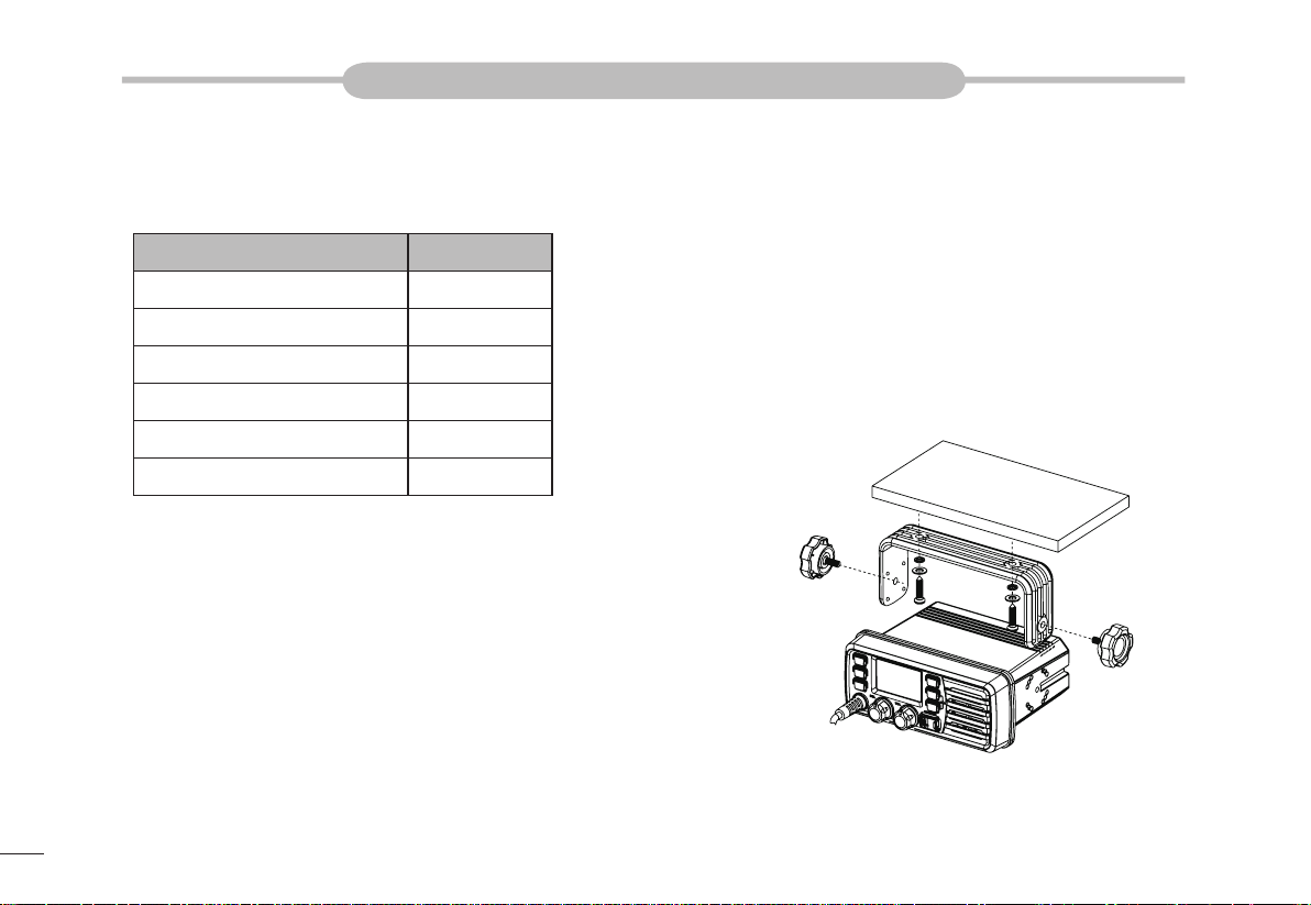
Supplied accessories
The following accessories are supplied:
ITEM QTY
DC power cable 1
Spare fuse 1
Mounting bracket 1
Screws for mounting bracket 1
Microphone hanger 1
Instruction manual 1
Transceiver mounting
Using the supplied mounting bracket
The universal mounting bracket supplied with your transceiver allows overhead
or dashboard mounting.
Fix the mounting bracket to shelf or dashboard with the supplied screws and 1.
mount the transceiver to the mounting bracket with the knob bolts.
Mount the transceiver so that the face of the transceiver is at 90°to your line 2.
of sight when operating it and tighten the knob bolts so that the transceiver
is securely mounted.
You may use a spongy cushion between the transceiver and
mounting bracket to reduce the vibration.
1
Page 5
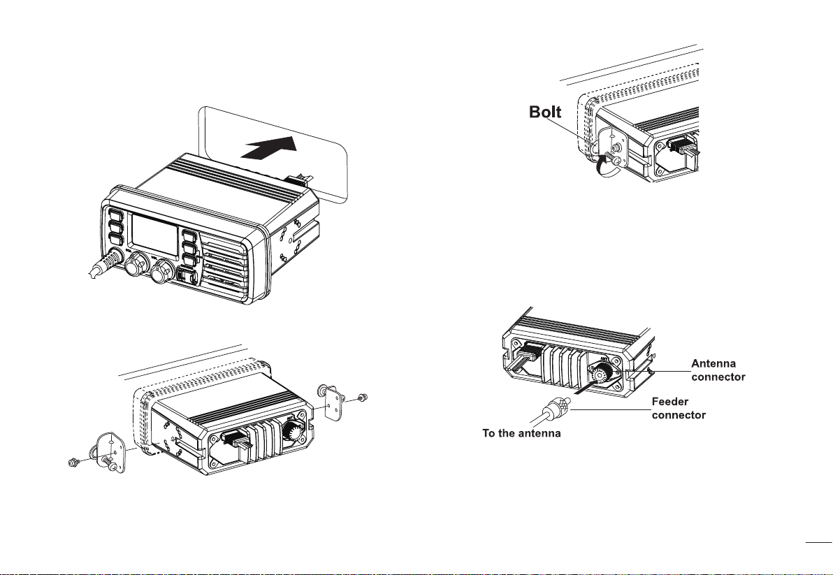
Embedded mounting
Cut a hole into the instrument panel (or wherever you plan to mount the 1.
transceiver).
Slide the transceiver through the holes as shown below.2.
Attach the clamps on either side of the transceiver with 2 supplied bolts. 3.
Antenna connection
Please connect an antenna before transmitting. Select the antenna with the relative
frequency and connect on the ANT antenna connector. Use the antenna and low
loss concentric with the same natural impedance 50Ω.
Transmitting without an antenna may damage the trans-
ceiver.
Tighten the end bolts on the clamps so that the clamps press fi rmly against 4.
the inside of the instrument control panel.
Connections
After connecting the DC power cable, GPS receiver lead and external speaker lead,
cover the connector and leads with an adhesive tape as below, to prevent water
seeping into the transceiver.
2
Page 6
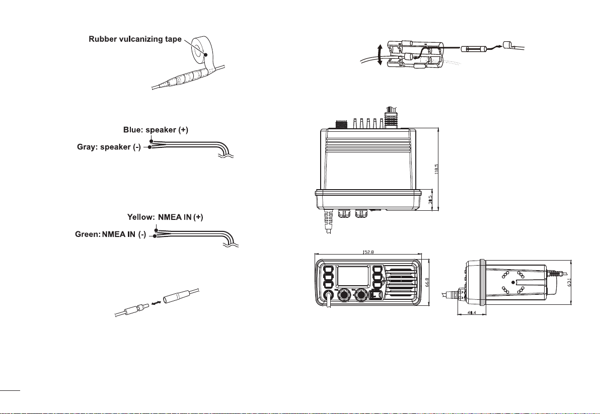
External speaker lead
Connect to an external speaker.
GPS receiver lead
Connect to a GPS receiver for position indication.
An NMEA0183 ver.2.0 or 3.01 (sentence formatters RMC, GGA, GNS,
GLL) compatible GPS receiver is required.
DC power connector
Connect the supplied DC power cable from this connector to an external 13.8V
DC power source. Do not connect to 24V storage battery.
DC15A/32V.
Dimensions
Fuse replacement
One fuse is installed in the supplied DC power cable. If a fuse blows or the transceiver stops functioning, track down the source of the problem, if possible, and
replace the damaged fuse with a new, rated one.
Please power off before replacing the fuse, the required fuse is
3
Page 7

PANEL DESCRIPTION
Front panel
Channel 16 / Call Channel Key [16]1.
→ Push to select Channel 16.
→ Push and hold for 1 sec. to select call channel.
“CALL” appears when the call channel is selected.
→ While pushing and holding [CH/WX], push [16] to enter the channel
comments programming condition.
→ Push to move the cursor backward.
→ While turning power ON, push [16] to enter set mode.
Channel / Weather Channel Key2.
→ Select and toggle the regular channel and weather channel when pushed
momentarily.
→ Push and hold for 1 sec. to start Dualwatch or Tri-watch.
→ Push to stop Dualwatch or Tri-watch when either is activated.
→ Push to move the cursor forward.
3. DSC / Position Key
→ Push to enter DSC menu.
→ Push and hold for 1 sec. to show the current position from a GPS receiver.
4. Squelch Control [SQL]
Rotate to set the squelch threshold level.
5. Power / Volume Control [VOL]
Rotate to turn the transceiver power ON and OFF and adjusts the audio level.
6. Distress Key [DISTRESS]
Push and hold for 5 sec. to transmit a Distress call.
7. Scan / Tag Key [SCAN]
→ Push to start or stop the normal or priority scan.
→ Push and hold for 1 sec. to set or clear the displayed channel as a TAG
(scanned) channel.
The favorite channels are set by the TAG channel setting.
→ Push and hold [HI/LO] and [SCAN] to clear all TAG channels in the selected
channel group.
Repeat above procedure to set all TAG channels.
8. [▲][▼] / [U/I/C]
→ Select the operating channels, set mode settings, etc.
→ While pushing and holding [SCAN], push [▲] or [▼] to adjust the brightness
of the LCD and key backlight.
→ Select one of three channel groups in sequence when both keys are
pushed.
→ While turning power ON, push and hold both keys to activate the AquaQuake
function.
4
Page 8
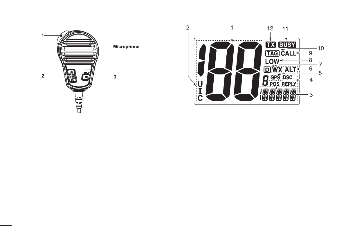
Microphone
[PTT]1.
Push and hold to transmit; release to receive.
Channel UP / DOWN Keys[▲]/[▼]2.
→ Push either key to change the operating channel, set mode settings, etc.
→ When the favorite channel function is turned ON, push either key to select
the favorite channels in the selected channel group in sequence.
Transmit Power Key [HI/LO]3.
→ Push to toggle the power high and low.
Some channels are set to low power only.
→ While push and hold [HI/LO], turn power ON to toggle the microphone
lock function ON and OFF.
5
Function display
Channel Number Readout1.
→ Indicate the selected operating channel number. (Refer to channel list)
→ In set mode, indicate the selected condition.
Channel Group Indicator2.
Indicate whether a U.S.A. “U”, International “I” or Canadian “C” channel is
in use.
Channel Comment Indicator3.
→ Channel comment appears if programmed.
→ “LOW BATTERY” scrolls when the battery voltage drops approx. 10.8V
DC or below.
→ “SC” blinks during priority scan; “SCAN” blinks during normal scan.
→ “DW” blinks during Dualwatch; “TW” blinks during Tri-watch.
DSC Indicators4.
→ “DSC” appears when a DSC call is received.
→ “POS REPLY” appears when a position reply call or position report reply
Page 9

call is received.
GPS Indicator5.
→ Appears while valid position data is received.
→ Blinks when invalid position data is received.
→ Disappears when no GPS receiver is connected.
Weather Channel Indicator6.
→ “WX” appears when a weather channel is selected.
→ “WX ALT” appears when the weather alert function is in use; blinks when
an alert tone is received.
Duplex Indicator7.
Appears when a duplex channel is selected.
Low Power Indicator8.
Appears when low power is selected.
Call Channel Indicator9.
Appears when the call channel is selected.
TAG Channel Indicator10.
Appears when a TAG channel is selected.
Busy Indicator11.
Appears when receiving a signal or when the squelch opens.
Transmit Indicator12.
Appears while transmitting.
6
Page 10

BASIC OPERATION
Power ON / OFF
Rotate [VOL] clockwise to turn power on;1.
Rotate [VOL] counter-clockwise to turn power off.2.
Receiving and transmitting
Transmitting
Push 1. [HI/LO] on the microphone to select the output power if necessary.
”LOW” appears when low power is selected.
Choose low power for short range communication, choose high power for
longer distance communication.
Some channels are for low power only.
Push and hold 2. [PTT] to transmit, then speak into the microphone.
“TX” appears.
Channel 70 cannot be used for transmission other than DSC.
Release 3. [PTT] to receive.
Note:
Do not transmit before connecting the antenna, this will ruin the trans-
ceiver.
The TOT (Time-out T imer) function inhibits continuous transmission over a
preset time period after the transmission starts.
Receiving
Set the audio and squelch levels.1.
Rotate 2. [SQL] fully counterclockwise in advance.
Rotate 3. [VOL] to adjust the audio output level.
Rotate 4. [SQL] clockwise until the noise disappears.
“When receiving a signal, ”
speaker.
7
”appears and audio is emitted from the
Channel group selection
The transceiver is pre-programmed with 59 U.S.A., 59 international and 63 Canadian channels. These channel groups may be specifi ed for the operating area.
Push [CH/WX] to select a regular channel.1.
If a weather channel appears, push [CH/WX] again.
Push 2. [U/I/C] (both [▲] and [▼] on the transceiver to change the channel
group, if necessary.
U.S.A., International and Canadian channel groups can be selected in
sequence.
Push 3. [▲] or [▼] to select a channel.
”appears for duplex channels.
”
Channel selection
Channel 16
Channel 16 is the distress and safety channel. It is used for establishing initial
contact with a station and for emergency communication. Channel 16 is monitored during both Dual-watch and Tri-watch. While standing by , you must monitor
Channel 16.
Page 11

Push 1. [16] momentarily to select Channel 16.
Push 2. [CH/WX] to return to the condition before selecting Channel 16, or
push [▲] or [▼] to select operating channel.
“WX” appears when a weather channel is selected.
“WX ALT” appears when the weather alert function is in use.
Push 2. [▲] or [▼] to select a channel.
Convenient:
When the favorite channel function is turned ON, [▲]/[▼] keys on the microphone select the favorite channels in the selected channel group in sequence
when pushed.
The favorite channels are set by the TAG channel setting. (P.10)
Channel 9 (Call channel)
Each regular channel group has a separate leisure-use call channel (Channel 9;
default). The call channel is monitored during Tri-watch.
Push and hold 1. [16] for 1 sec. to select the call channel of the selected channel group. “CALL” and call channel number appear.
Push 2. [CH/WX] to return to the condition before selecting call channel, or
push [▲] or [▼] to select a channel.
Weather channels
The transceiver has 10 pre-programmed weather channels. The transceiver can
automatically detect a weather alert tone on the selected weather channel while
receiving the channel or during scanning.
Push [CH/WX] once or twice to select a weather channel.1.
Call channel programming
Call channel is used to select Channel 9 (default), however, you can program the
call channel with your most offer-used channel in each channel group for quick
recall.
Push 1. [U/I/C] (both [▲] and [▼] on the transceiver several times to select the
desired channel group (U.S.A., International or Canada) to be programmed.
Push and hold 2. [16] for 1 sec. to select the call channel of the selected chan-
nel group.
“CALL” and call channel number appear.
Push and hold 3. [16] again for 3 sec. (until a long beep changes to 2 short
beeps) to enter call channel programming condition.
Channel number starts blinking.
Push 4. [▲] or [▼] to select the desired channel.
Push 5. [16] to program the displayed channel as the call channel.
Push [CH/WX] to cancel.
8
Page 12

Channel comments
Memory channels can be labeled with a unique alphanumeric ID of up to 10 characters each. More than 6 characters comment scrolls automatically at the channel
comment indicator after the channel selection.
Capital letters, small letters (except f, j, k, p, s, v, x, z), 0 to 9, some symbols (=*+ - .
/) and space can be used.
Select the desired channel.1.
Cancel Dualwatch, Tri-watch or scan in advance.
While pushing 2. [CH/WX], push [16] to edit the channel comment.
A cursor and the fi rst character start blinking alternately.
Pushing 3. [▲] or [▼] to select the desired character.
Push [16] or [CH/WX] to move the cursor forward or backward, respec-
tively.
Repeat step 4. ③ to input all characters.
Push 5. [DSC] to input and set the comment.
Push [SCAN] to cancel.
The cursor and the character stop blinking.
microphone. This prevents accidental channel
changes and function access.
→ While pushing and holding [HI/LO] on the
microphone, turn power ON to toggle the
microphone lock function ON and OFF.
Display backlighting
The function display and keys can be backlit
for better visibility under low light conditions.
→ While pushing and holding [SCAN], push [▲] or [▼] to adjust the brightness of
the LCD and key backlight.
The backlight is selectable in 3 levels and OFF.
AquaQuake water draining function
AquaQuake helps drain water away from the speaker housing (water that might
otherwise muffl e the sound coming from the speaker). The transceiver emits a vi-
brating noise when this function is being used.
While pushing and holding 1. [▲] and [▼], turn power ON.
“AQUA QUAKE” appears.
A low beep tone sounds while 2. [▲] or [▼] keys are held to drain water, regardless of [VOL] control setting.
The transceiver never accepts a key operation while the AquaQuake func-
tion is activated.
Microphone lock function
The microphone lock function electrically locks [▲] and [▼] keys on the supplied
9
Page 13

SCAN OPERATION
Scan types
The transceiver has priority scan and normal scan. (Refer to set mode programming).
When the weather alert function is turned ON, the previously selected (last used)
weather channel is also checked while scanning.
Set the TAG channels (scanned channels) before scanning. Clear the TAG channels which inconveniently stop scanning.
Normal scan:
Normal scan searches through all TAG channels in sequence. Channel 16 is not
checked unless Channel 16 is set as a TAG channel.
Priority scan:
Priority scan searches though all TAG channels in sequence while monitoring
Channel 16.
Setting TAG channels
For more effi cient s c a nn in g, a dd d e si re d c ha nn e ls a s TAG chann el s o r c le a r th e
TAG for unwanted channels.
Channels that are not tagged will be skipped during scanning.
Setting / clearing a single tagged channel
Push 1. [U/I/C] (both [▲] and [▼]) several times to select the desired channel
group.
Select the desired channel to be set as a TAG channel.2.
Push and hold 3. [SCAN] for 1 sec. to set the displayed channel as a TAG
channel.
”appears in the display.
”
To cancel the TAG channel setting, repeat step 4. ③.
”disappears.
”
Setting / clearing all tagged channels
While pushing and holding 1. [HI/LO] on the microphone, push [SCAN] for 3
sec. to clear all TAG channels in the selected channel group.
Repeat above procedure to set all TAG channels.2.
Starting a scan
Set scan resume timer in advance using Set mode.
Push 1. [SCAN] to start priority or normal scan.
“SC” blinks during priority scan; “SCAN” blinks during normal scan.
Channel 16 is monitored during priority scan.
Push [▲] or [▼] to change the scanning direction.
A beep tone sounds and “SC 16” blinks at the channel comment indicator
when a signal is received on Channel 16 during priority scan.
To stop the scan, push 2. [SCAN].
10
Page 14

DUAL-WATCH / TRI-WATCH
Description
The transceiver has Dualwatch and Tri-watch.
Dualwatch monitors Channel 16 while you are receiving on another channel.
Tri-watch monitors Channel 16 and the call channel while receiving another chan-
nel.
Operation
Select Dualwatch or Tri-watch in set mode.1.
Select the desired channel.2.
Push and hold 3. [CH/WX] for 1 sec. to start Dualwatch or Tri-watch.
“DW” blinks during Dualwatch; “TW” blinks during Tri-watch.
A beep tone sounds when a signal is received on Channel 16.
To cancel Dualwatch or Tri-watch, push 4. [CH/WX].
11
Page 15

DSC OPERATION
MMSI code programming
The 9-digit MMSI (Maritime Service Identity: DSC self ID) code can be programmed
at power ON.
Rotate 1. [VOL] to turn power OFF.
While pushing and holding 2. [DSC], turn power ON to enter MMSI code pro-
gramming condition.
After the display appears, release 3. [DSC], a cursor starts blinking.
Check the 9-digit MMSI (DSC self ID) code.3.
The MMSI code is displayed and scrolls at the channel comment indica-
tor.
Push 4. [DSC] to return to the normal operation.
Edit the specifi ed MMSI code by pushing 4. [▲] or [▼].
Push [16] or [CH/WX] to move the cursor forward or backward, respec-
tively.
Input 9-digit code, then push 5. [DSC] to set the code.
Returns to the normal operation.
Note:
This code programming can be performed only twice. After the code pro-
gramming, it can be changed only by your dealer or distributor.
MMSI code check
The 9-digit MMSI (DSC self ID) code can be checked.
Push 1. [DSC] to enter the DSC menu.
Push 2. [▲] or [▼] to select “MMSI” and push [DSC].
DCS address ID
A total of 30 DSC address IDs (9-digit) can be programmed and named with up to
5 characters.
Programming address ID
Push 1. [DSC] to enter the DSC menu.
Push 2. [▲] or [▼] to select “ADDRESS”, and push [DSC].
Push 3. [▲] or [▼] to select “ADD”, and push [DSC].
12
Page 16

When no address ID is programmed, “NO ID” is displayed.
Push 4. [▲] or [▼] to input 9-digit of the appropriate address ID.
Push [16] or [CH/WX] to move the cursor forward or backward, respec-
tively.
Push [SCAN] to cancel and exit the condition.
st
Note: 1
digit “0” is fi xed for a group ID. When you input 1
the ID is automatically registered as a group ID.
After inputting 9-digit ID, push 5. [DSC] to input 5 characters ID name using
[▲] or [▼].
P ush [16] or [CH/WX] to move the cursor forward or backward, respec-
tively.
P u sh [SCAN] to cancel and exit the condition.
Push 6. [DSC] to program and exit the DSC menu.
st
digit “0” and other 8 digits,
Deleting address ID
Push [DSC] to enter the DSC menu.1.
Push [▲] or [▼] to select “ADDRESS” and push [DSC].2.
Push 3. [▲] or [▼] to select “DEL”, then push [DSC].
13
Push 4. [▲] or [▼] to select the desired ID name for deleting and push [DSC],
“READY” appears.
Distress call
A Distress call should be transmitted if, in the opinion of the master, the ship or a
person is in distress and requires immediate assistance.
Note: Never use the Distress call when your ship or a person is not in an emer-
gency. A Distress call can be used only when immediate help is needed.
Transmitting a Distress call
While opening the key cover, push 1. [DISTRESS] for 5 sec. to transmit the
Distress call.
Emergency channel (Channel 70) is automatically selected and the Dis-
tress call is transmitted.
After transmitting the call, the transceiver waits for an acknowledgment call 2.
on Channel 70.
The Distress call is automatically transmitted about every 4 minutes.
“DSC REPEAT” scrolls at the channel comment indicator.
Page 17

After receiving the acknowledgment, reply using the microphone. 3.
“RCV DISTRESS ACK” scrolls at the channel comment indicator.
Push and hold 4. [DISTRESS] for 5 sec. to transmit a re-newed Distress call,
if desired.
Push any key except 5. [DISTRESS] to cancel the ‘call repeat’ mode.
Note: A distress alert contains:
Kinds of distress: Undesignated distress
Position data: GPS position data held until receiving an ‘acknowledge-
ment’.
Receiving a Distress call
While monitoring Channel 70 and a Distress call is received:
The emergency alarm sounds.1.
Push any key to stop the alarm.
“DSC” appears and “RCV DISTRESS” scrolls at the channel comment indi-2.
cator, then Channel 16 is automatically selected.
Continue monitoring Channel 16 as a coast station may require assistance.3.
Receiving a Distress acknowledgement
While monitoring Channel 70 and a Distress acknowledgement to other ship
is received:
The emergency alarm sounds.1.
Push any key to stop the alarm.
“DSC ” appear s and “RC V DISTRES S ACK” s crolls a t the chan nel com -2.
ment indicator, then Channel 16 is automatically selected.
Receiving a Distress Relay call
While monitoring Channel 70 and a Distress Relay acknowledgement is received:
The emergency alarm sounds.1.
Push any key to stop the alarm.
“DSC” appears and “RCV RELAY” scrolls at the channel comment indicator, 2.
then Channel 16 is automatically selected.
Individual call
The Individual call function allows you to transmit a DSC signal to a specifi c ship
only.
Transmitting Individual call
Push [DSC] to enter the DSC menu.1.
“INDIVIDUAL” scrolls at the channel comment indicator.
14
Page 18

Push 2. [DSC] to select the desired pre-programmed individual address using
[▲] or [▼], then push [DSC].
The ID code for the Individual call must be set in advance.
Push 3. [▲] or [▼] to select a desired intership channel, push [DSC].
Intership channels are already preset into the transceiver in recommend-
ed order.
Channel 70 is selected and “READY” appears after pushing [DSC].
Push 4. [DSC] to transmit the Individual call.
If Channel 70 is busy, the transceiver stands by until the channel becomes
clear.
After transmitting the Individual call, standby on Channel 70 until an acknowl-5.
edgement is received.
“WAIT ACK” scrolls at the channel comment indicator.
When the acknowledgement ‘Able to comply’ is received, the specifi ed chan-6.
nel (in step ③) is selected with beeps automatically. Or, when the acknowledgement ‘Unable to comply’ is received, the display returns to the operated
channel (before entering the DSC menu) with beeps.
“RCV ABLE ACK” OR “RCV UNABLE ACK” scrolls at the channel com-
ment indicator.
Push and hold 7. [PTT] to communicate your message to the responding ship
when ‘Able to comply’ is received.
Transmitting Individual acknowledgement
When receiving an Individual call, you can transmit an acknowledgement
(‘Able to comply’ or ‘Unable to comply’) by using the on screen prompts (refer
to “Receiving an Individual call”). You can also send an acknowledgement
through the menu system as follows.
Push 1. [DSC] to enter the DSC menu.
Push 2. [▲] or [▼] to select “INDV ACK” and push [DSC].
“INDV ACK” item appears after an Individual call is received.
“INDV ACK” item disappears if another call is received after the Individual
call.
The Individual acknowledgement can be transmitted to the last received
Individual call only.
Push 3. [▲] or [▼] to select the acknowledgement “ABLE” or “UNABL”.
15
Page 19

Push 4. [DSC] to enter the standby condition for Individual acknowledgement
call.
“READY” appears at the channel comment indicator.
Push 5. [DSC] to transmit the acknowledgement to the selected station.
After the Individual acknowledgement has been transmitted, the display 6.
changes to the channel specifi ed by the calling station automatically when
“ABLE” is selected.
The emergency alarm or beeps sound depending on the received category.1.
“DSC” appears and “RCV INDIVIDUAL” scrolls at the channel comment in-2.
dicator.
Push any key to stop beep.3.
Push 4. [DSC] to reply the call and select the channel specifi ed by the calling
station for voice communication; Push any other key to ignore the Individual
call.
Group call
The Group call function allows you to transmit a DSC signal to a specifi c group
only.
Transmitting Group call
Push 1. [DSC] to enter the DSC menu.
Push 2. [▲] or [▼] to select “GROUP”, and push [DSC].
Push 3. [▲] or [▼] to select the desired pre-programmed group address, and
push [DSC].
The ID code for the Group call must be set in advance.
Receiving an Individual call
While monitoring Channel 70 and an Individual call is received:
16
Page 20

Push 4. [▲] or [▼] to select the desired intership channel, and push [DSC].
Channel 70 is selected and “READY” appears.
Push any key to stop beep.3.
Push 4. [DSC] to select the channel specifi ed by the calling station for voice
communication; Push any other key to ignore the Group call.
Push 5. [DSC] to transmit the Group call.
If Channel 70 is busy, the transceiver stands by until the channel become
clear.
After the Group call has been transmitted, the display changes to the previ-6.
ously specifi ed channel.
Push and hold 7. [PTT] to communicate your message to the responding
ship.
Receiving a Group call
While monitoring Channel 70 and a Group call is received:
The emergency alarm or beeps sound depending on the received category.1.
“DSC” appears and “RCV GROUP” scrolls at the channel comment indica-2.
tor.
17
All Ships call
The All Ships call function allows you to transmit a DSC signal to all
ships.
Transmitting All Ships call
Large ships use Channel 70 as their ‘listening channel’. When you want to announce a message to these ships, use the ‘All Ships call” function.
Push 1. [DSC] to enter the DSC menu.
Push 2. [▲] or [▼] to select “ALL SHIPS”.
Push 3. [DSC] to enter the standby condition for All Ships call.
Channel 70 is selected and “READY” appears.
Push 4. [DSC] to transmit the All Ships call.
Page 21

Low power is selected.
After the All Ships call has been transmitted, the display changes to Channel 5.
16 automatically.
Receiving an All Ships call
While monitoring Channel 70 and an All Ships call is received:
The emergency alarm sounds when the category is ‘Distress’ or ‘Urgency’; 2 1.
beeps sound for other categories.
“DSC” appears and “RCV ALL SHIPS” scrolls at the channel comment in-2.
dicator.
Push any key to stop beep.3.
Push 4. [DSC] to monitor channel 16 for an announcement from the calling
vessel, push any other key to ignore the call.
Receiving a Geographical Area call
While monitoring Channel 70 and a Geographical Area call (for the area you
are in) is received:
The emergency alarm or beeps sound depending on the received category.1.
“DSC” appears and “RCV GEOGRAPHICAL” scrolls at the channel comment 2.
indicator.
Push any key to stop the beep.3.
Push 4. [DSC] to change to the channel specifi ed by the calling station for
voice communication; Push any other key to ignore the Geographical Area
call.
Position indication
Positioning instructions
When a GPS receiver is connected, the transceiver indicates the current position
data in seconds of accuracy.
A NMEA0183 ver . 2.0 or 3.01 (sentence formatters RMC, GGA, GNS, GLL) compatible GPS receiver is required.
Push and hold [DSC] for 1 sec. to display the current position.
‘Latitude’ and ‘Longitude’ scroll in sequence at the channel comment
indicator.
“NO POSITION” scrolls when no GPS is connected.
“GPS” blinks when the GPS data is invalid.
Geographical Area call
The Geographical Area call function allows you to transmit a DSC signal to all ships
in a geographical area.
18
Page 22

Transmitting Position Request call
Transmit a Position Request call when you want to know a specifi ed ship’s cur-
rent position, etc.
Push 1. [DSC] to enter the DSC menu.
Push 2. [▲] or [▼] to select “POS REQUEST”, then push [DSC].
Push 3. [▲] or [▼] to select the desired pre-programmed individual address.
The ID code for position request must be set in advance.
Push 4. [DSC] to enter the standby condition for Position Request call.
Channel 70 is selected and “READY” appears.
“WAIT ACK” scrolls at the channel comment indicator.
Push any key to exit the condition and return to the normal operation.7.
Transmitting Position Report call
Transmit a Position Report call when you want to announce your own position to
a specifi c ship and to get an answer, etc.
Push 1. [DSC] to enter the DSC menu.
Push 2. [▲] or [▼] to select “POS REPORT”, and push [DSC].
Push 3. [▲] or [▼] to select the desired pre-programmed individual address.
The ID code for the position report call can be set in advance.
Push 5. [DSC] to transmit the Position Request call.
After the Position Request call has been transmitted, the following indication 6.
is displayed.
19
Push 4. [DSC] to enter the standby condition for Position Report call.
Channel 70 is selected and “READY” appears.
Push 5. [DSC] to transmit the Position Report call.
Page 23

After the Position Report call has been transmitted, stand by on Channel 70 6.
until an acknowledgement is received.
“WAIT ACK” scrolls at the channel comment indicator.
Push any key to exit the condition and return to the normal operation.7.
Receiving a Position Request call
While monitoring Channel 70 and a Position Request call is received:
“DSC” appears and “RCV POS REQUEST” scrolls at the channel comment 1.
indicator.
Push any key to stop the beep.2.
Push 3. [DSC] to reply to the call; Push any other key to ignore the call.
Receiving a Position Report call
While monitoring Channel 70 and a Position Report call is received:
“DSC” appears and “RCV POS REPORT” scrolls at the channel comment 1.
indicator.
Push any key to stop the beep.2.
Push 3. [DSC] to reply to the call; Push any other key to ignore the call.
The ‘Latitude’ and ‘Longitude’ from the called station is displayed and
scrolled automatically in order of Latitude co-ordinates and then Longitude
co-ordinates after replying the call.
Receiving a Position Reply call
While monitoring Channel 70 and a Position Reply call is received:
“DSC” and “POS REPLY” appear in the display.1.
The ‘Latitude’ and ‘Longitude’ from the called station is displayed and
scrolled automatically in order of Latitude co-ordinates and then Longitude co-ordinates.
Push any key to stop the beep.2.
Receiving a Position Report Reply call
While monitoring Channel 70 and a Position Report Reply call is received:
“DSC” and “POS REPLY” appear in the display.1.
The ‘Latitude’ and ‘Longitude’ you have sent is displayed and scrolled
automatically in order of Latitude co-ordinates and then Longitude coordinates.
Push any key to stop the beep.2.
20
Page 24

SET MODE
Set mode programming
Set mode is used to change the conditions of the transceiver’s functions: Scan type
(Normal or Priority), Scan resume timer, Weather alert, Dual/T ri-watch, DSC watch,
Beep tone, Auto acknowledgement and Favorite channel function.
Set mode operation
Turn power OFF.1.
While pushing [16], turn power ON to enter Set mode.2.
After the display appears, release [16].3.
“SCAN” appears at the channel comment indicator.
Push [16] to select the desired item, if necessary.4.
Push [▲] or [▼] to select the desired condition of the item.5.
Turn power OFF, then ON again to exit Set mode.6.
No. Display Item Option Default
1 SCAN Scan type
2 TIMER
3 WX ALERT Weather alert of (OFF) / on (ON) of (OFF)
4 DUAL Dual/Tri-watch
5 DSC WATCH DSC watch of (OFF) / on (ON) of (OFF)
6 BEEP Beep tone of (OFF) / on (ON) on (ON)
7 AUTO ACK
8 FAVORITE CH Favorite channel of (OFF) / on (ON) on (ON)
Set mode items
Scan type
21
Scan resume
timer
Auto acknowledgement
n- (normal scan)
/ p- (priority scan)
of (OFF) / on (ON) of (OFF)
d-(Dualwatch)
/ t- (Tri-watch)
of (OFF) / on (ON) of (OFF)
n- (normal
scan)
d-(Dualwatch)
The transceiver has 2 scan types: Normal scan and Priority scan. Normal scan
searches all TAG channels in the selected channel group. Priority scan searches
all TAG channels in sequence while monitoring Channel 16.
Scan resume timer
The scan resume timer can be selected as a pause (OFF) or timer scan (ON).
When OFF is selected, the scan pauses until the signal disappears. When ON is
selected, the scan pauses 5 sec. and resumes even if a signal has been received
on any other channel than Channel 16.
Weather alert
A NOAA broadcast station transmits a weather alert tone before important
weather information. When the weather alert function is turned ON, the transceiver detects the alert, then the “WX ALT” indicator blinks until the transceiver is
operated. The previously selected (used) weather channel is checked any time
while scanning.
“WX ALT” appears instead of “WX” indication when the function is set
ON.
Dual / Tri-watch
This item can be selected as Dualwatch or Tri-watch.
DSC watch
DSC watch monitors Channel 70 while you are receiving another channel.
If a distress signal is received on Channel 70, the transceiver monitors Channel
16 and 70 alternately until the distress signal disappears. If a signal is received
on another channel, DSC watch pauses until the signal disappears.
This function may not be available for some channel groups depending
on dealer setting.
“DSC WATCH” scrolls at the channel comment indicator.
Beep tone
Page 25

You can select silent operation by turning beep tones OFF or you can have confi rmation beeps sound at the push of a key by turning beep tones ON.
Automatic acknowledgement
This item sets the Automatic acknowledgement function ON or OFF.
When Position Request call or Position Report call is received, transceiver au-
tomatically transmits Position Request Reply call or Position Report Reply call,
respectively.
“AUTO ACK” scrolls at the channel comment indicator.
Favorite channel
This item sets the Favorite channel function ON or OFF.
The favorite channel is programmed by the TAG channel setting.
When the Favorite channel function is turned ON, [▲] or [▼] keys on the micro-
phone select the favorite channels in the selected channel group in sequence
when pushed.“FAVORITE CH” scrolls at the channel comment indicator.
Operational Instructions and Training Guidelines
To ensure optimal performance and compliance with the General Public (Uncontrolled Environment) RF energy exposure limits in the above standards and guidelines,
users should transmit not more than 50% of the time and always adhere to the following procedures:
● The antenna must be installed complying with the requirements of manufacturer or supplier,
and it must be at least 1.5 meters away from human body.
Antenna Gain=3.00dBi for model No.:TQJ-GB-3-159.5V
Antenna Gain=3.50dBi for model No.:MA-F-3.5-162V-09A(MA-F09A)
22
Page 26

CHANNEL LIST
Channel number Frequency(MHz) Channel number Frequency(MHz) Channel number Frequency(MHz) Channel number Frequency(MHz)
USA INT CAN Transmit Receive USA INT CAN Transmit Receive USA INT CAN Transmit Receive USA INT CAN Transmit Receive
01 01 156.050 160.650 21 21 157.050 161.650 68 68 68 156.425 156.425 86A 157.325 157.325
01A 156.050 156.050 21A 21A 157.050 157.050 69 69 69 156.475 156.475 87 87 87 157.375 161.975
02 02 156.100 160.700 21b
Only receiver
161.650 70*370*370*3156.525 156.525 87A 157.375 157.375
03 03 156.150 160.750 22 157.100 161.700 71 71 71 156.575 156.575 88 88 88 157.425 162.025
03A 156.150 156.150 22A 22A 157.100 157.100 72 72 72 156.625 156.625 88A 157.425 157.425
04 156.200 160.800 23 23 157.150 161.750 73 73 73 156.675 156.675
04A 156.200 156.200 23A 157.150 157.150 74 74 74 156.725 156.725
05 156.250 160.850 24 24 24 157.200 161.800 75*1 75*1 75*1 156.775 156.775
05A 05A 156.250 156.250 25 25 25 157.250 161.850 76*1 76*1 76*1 156.825 156.825
06 06 06 156.300 156.300 25b
Only receiver
161.850 77*1 77 77*1 156.875 156.875
07 156.350 160.950 26 26 26 157.300 161.900 78 156.925 161.525
07A 07A 156.350 156.350 27 27 27 157.350 161.950 78A 78A 156.925 156.925
08 08 08 156.400 156.400 28 28 28 157.400 162.000 79 156.975 161.575
09 09 09 156.450 156.450 28b
Only receiver
162.000 79A 79A 156.975 156.975
10 10 10 156.500 156.500 60 60 156.025 160.625 80 157.025 161.625
11 11 11 156.550 156.550 61 156.075 160.675 80A 80A 157.025 157.025
12 12 12 156.600 156.600 61A 61A 156.075 156.075 81 157.075 161.675
*2
13
13 13*1156.650 156.650 62 156.125 160.725 81A 81A 157.075 157.075
14 14 14 156.700 156.700 62A 156.125 156.125 82 157.125 161.725 1
*215*115*1
15
156.750 156.750 63 156.175 160.775 82A 82A 157.125 157.125 2
16 16 16 156.800 156.800 63A 156.175 156.175 83 83 157.175 161.775 3
*1
17
17 17*1156.850 156.850 64 64 156.225 160.825 83A 83A 157.175 157.175 4
18 156.900 161.500 64A 64A 156.225 156.225 83b
Only receiver
161.775 5
18A 18A 156.900 156.900 65 156.275 160.875 84 84 84 157.225 161.825 6
19 156.950 161.550 65A 65A 65A 156.275 156.275 84A 157.225 157.225 7
19A 19A 156.950 156.950 66 156.325 160.925 85 85 85 157.275 161.875 8
20 20 20
20A 157.000 157.000 67
*1
Low power only. *2Momentary high power. *3DSC operation.
23
*1
157.000 161.600 66A 66A 66A*1156.325 156.325 85A 157.275 157.275 9
*2
67 67 156.375 156.375 86 86 86 157.325 161.925 10
WX channel
Frequency(MHz)
Transmit Receive
Only receiver
Only receiver
Only receiver
Only receiver
Only receiver
Only receiver
Only receiver
Only receiver
Only receiver
Only receiver
162.550
162.400
162.475
162.425
162.450
162.500
162.525
161.650
161.775
163.275
Page 27

SPECIFICATIONS
General
Frequency coverage
Mode FM (16K0G3E) DSC (16K0G2B)
Frequency stability ± 10ppm
Operating temperature range -20°C ~ +60°C
Antenna impedance 50Ω
Dimensions (W×D×H) 153mm×152mm×67mm
Weight (main unit) 742g (with microphone)
TROUBLESHOOTING
Issues described in the following table are some common operational failure. These types of errors are generally due to improperly connected, the operation caused by incorrect
settings, or operator error caused due to incomplete programming. These problems are usually not caused by circuit failure. Before suspect intercom failure, please refer to the
relevant parts of these forms and the instructions for use.
Question Possible Cause Solutions Reference page
Power did not respond.
Unable to connect with GPS. 1. connection error.
Can not be scanned. Not set mark channels (TAG). The channel you want to scan is set to mark channels. 10
Can not launch. Work on the weather channel or 70 channels. Exit the weather channel or 70 channels. 4,8
High power can not be selected. Some channels can transmit at low power. Choose other channels. 5,7
The same channel can not talk.
No beep Beep off Open the beep function in the settings mode. 22
Can not transmit a distress call. MMSI code is not set. Hold down the [DSC] key to boot into MMSI setting mode. 12
No sound from the speaker.
TX: 156.025-157.425 MHz
RX: 156.050 -163.275 MHz
1.the power cable is connected well.
2. the power cable fuse broken.
3. the voltage exceeds 17V or below 9V.
2. different external GPS format.
1, the channel is different frequency (DUP).
2, the working group on its own channel.
1, tone squelch level too.
2, the volume is too small.
3, the speaker grid water.
Output power 25W / 1W
Max. frequency deviation ±5.0 kHz
Spurious emissions
Adjacent channel power ≥70dB
Audio harmonic distortion ≤10%
Current drain
Input resistance 2kΩ
Transmitter
Sensitivity ≤0.2uV
Squelch sensitivity ≤0.2uV
≤-70dB (H)
≤-56dB (L)
≤5.5A (H)
≤1.5A (L)
1, check the power cable is connected correctly: red (+); black (-).
2, then fi nd the cause of blown fuse, replace the fuse current to 15A.
3, adjust the power supply is 13.8V.
1, check the connections are correct.
2, external GPS format should be NMEA0183-2.0.
1, select a channel.
2, the channel is set to the same frequency.
1, rotate [SQL] knob to adjust the squelch level.
2, rotate [VOL] knob to adjust the volume.
3, the use of vibration drainage water discharge.
Adjacent channel selectivity ≥70dB
Spurious response rejection ratio ≥70dB
Intermodulation rejection ratio ≥70dB
Max. current ≤1.5A
Audio output power ≥4.5W (10%)
GPS signal ver. NMEA0183-2.0
Output impendence 4Ω
Receiver
3
3
5,7
7,9
24
Page 28

 Loading...