

PRICE 0NE DOlLAR
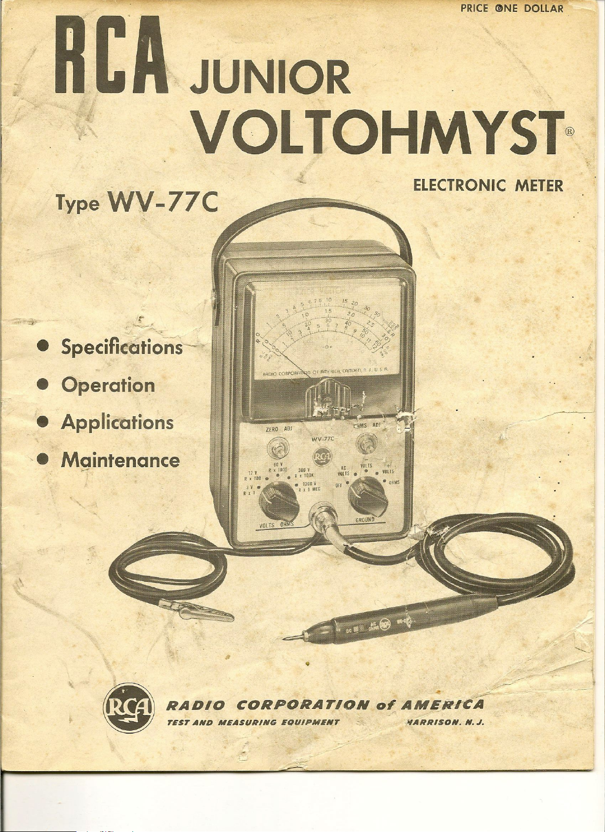
Type WV-77C
r
~:..
".-:.
.~
• SpecifkatioriS~
JUNIOR
,
VOLTOHMYST®
ELECTRONIC METER
• Operation
• Applications
'. Maintenance
--
ZfRO AUI
~ WV_77C
..;:~s
AOJ~· ~).
..
~"
"
i~ ,~ ~
V ~.' \~)'
6QV ~'
12 V R ~ fOOQ
R , 1D~. • • R. 1001( VOLTS.·. VOlTS
JOD
v
.IZOOV Off .~. 0 liS
~ , 1 NEG H
At VDtTS -
+'
•
,
~~-
RADIO CORPORATION
TEST AND MEASURING EOUIPMENT ~ ,"ARRISON_ N.
0'
AMEN-rCA
,
y---
J.
Safety Precautions
The metal case of this instrument is connected to
the ground of the internal circuit. For
tion, the ground cable of the WV-77C should always be
connected to the ground of the equipment uncler test.
The WG-299B DC/AC-Ohms Probe and Cable has a
shield throughout its length which is connected to the
instrument ground and case. Always handle the WG·
2998 by the insulated probe housing.
An important point to remember is that there is
always danger inherent in testing electrical equipment
which operates at hazardous voltages. Therefore, the
operator should thoroughly familiarize himself with
the equipment under test before working on it, bearing
in mind that high voltages may appear at unexpected
points in defective equipment. Additional precautions
which experience in the industry has shown to be
important are listed below.
l.
It is good practice to remove power before can·
necting test leads to high.voltage points.
impractical, be especially careful to avoid accidental
contact with equipment racks and other obj ects which
proper
If
opera-
this is
can provide a ground. Working with one hand in your
pocket and standing on a properly insulated floor les-
sens the danger of shock.
2. Filter capacitors may store a charge large
enough to be hazardous. Therefore, discharge filter
capacitors before attaching test leads.
3. Remember that leads with broken insulation
provide the additional hazard of high voltages appear·
ing at exposed points along the leads. Check test leads
for frayed or broken insulation before working with
them.
4. To lessen the danger of accidental shock, discon-
nect test leads immediately after test is completed.
5. Remember that the risk of severe shock is only
one of the possible hazards. Even a minor shock can
place the operator in hazard of more serious risks such
as a bad fall or contact with a source of high,er voltage.
6. The experienced operator continuously guards
against injury and does not work on h.~zardous circuits
unless another personisavailabk to \assist in case of
accident. ...... --...
L
ACCESSORIES
Supplied with WV·77C '" "'
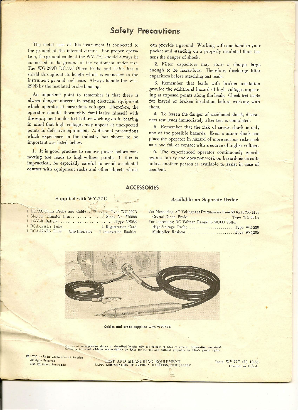
D~/AC-Oh~s Probe.and Cable .. ~
1 Shp-On . .lhgator Clip. . Stock No. 210088
I 1.5-Volt Battery. . . . . . . . . . . . . . .. . Type VS036
I RCA-I2AU7 Tube I Registration Card
I RCA·I2AL5 Tube Clip Insulator I Instruction Booklet
..-./
--'-1.'! '
r.
Type WG-299B
Cables and probe supplied with WV·77C
-:::;...~
Available on Separate 9rder
For Measuring AC Voltages at Frequencies from 50 Kc t0250 Me:
Crystal-Diode Probe Type WC.30IA
For Increasing DC Voltage Range to 50,000 Volts:
High-Voltage Probe ... . Type WG-289
NIultiplier Resistor .. . Type WG·206
..
Devices or arrangem~nt. ~ho""n or tle~cribed herein may ""C patenl~ of
her~ini.furni!hed withon' responsibility by
©
1956 by Rgdio Corporglion of Americg
All Rights Reserved
TMK ®, Mgrcg Regi.lrodg
RCA
RCA
for it~ use lint.! without prejutlice to
TEST AND MEASURING EQUIPMENT
RADIO CORPOHATION OF AMERICA, HARBISON, NEW J£H.SEY
or I)ther~. Information co[]tail]~d
,
RCA'&
patent
r;~"I~.
Inst'- WV-77C
Printed in U.S.A.
(l)
10-56
CONTENTS
Safety Precautions _ .
General Desci·jptlon ..
Functions of Controls and Terminals ...
Specifications .. .
Operation and Applications . ..
Accessories . .. ..
Special Applications ..
11aintenance .. . ..
Schema tie Diagram
Replacement Parts List
Page
2
4
4
5
5
8
8
9
10
11
~
Q
'"
U
0
~ +3
~
~
~
'"
I
a
§
z
~
~
-
-'
w
>
W
-'
W
U
Z
W
0:
W
~
W
0:
-'
'"
w
<D
U
w
a
~
~
<D
a
+4
+2
0.1
-
.
0
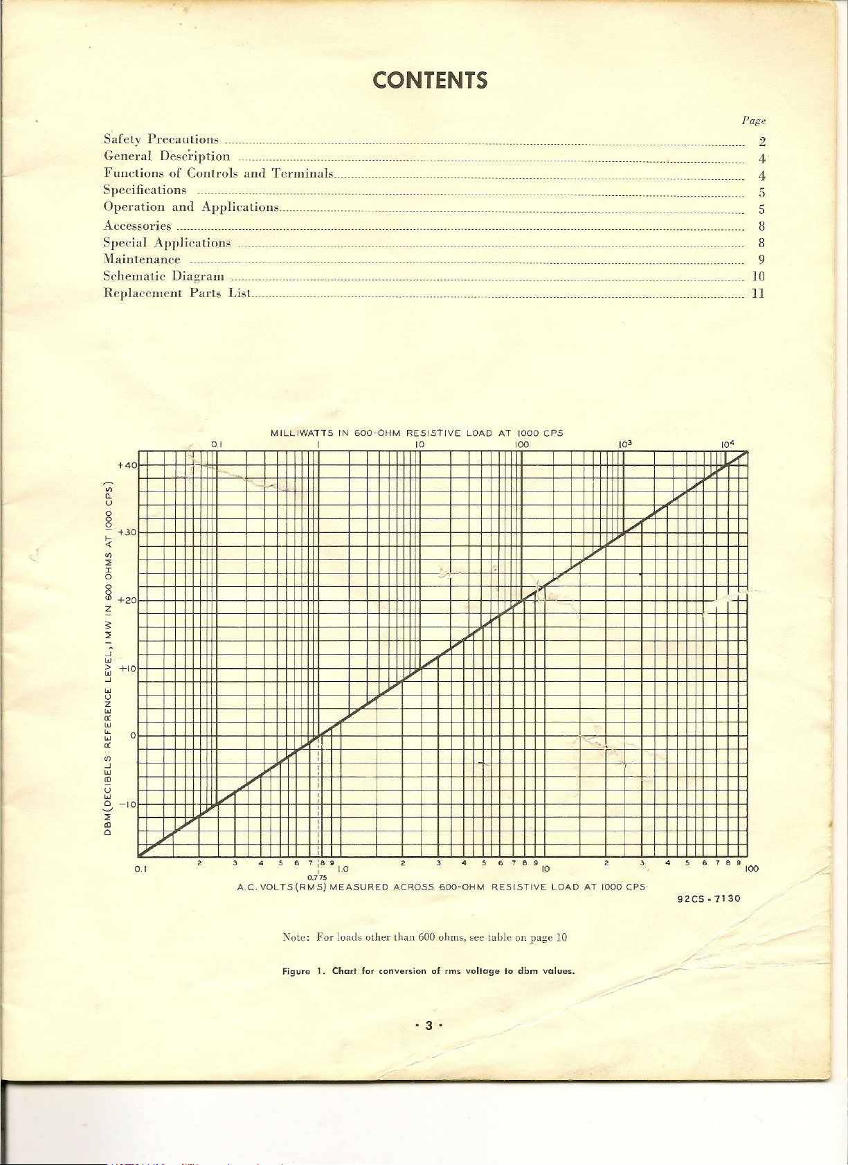
MILl1WATTS IN 600-0HM RESISTIVE LOAD AT 1000 CPS
!
10 100
,- ,-
10'
-~
,
/
-"
6 7 8
\
.......
:-_.
•
g
10
, ,
,
92CS·7130
6 7 6
g
100
0
,
+1
1/
,
,
,
:
,
,
,
-I
0.1
D
, ,
4
A.C. VOLTS(RMS) MEASURED
,
,
,
,
,
,
,
,
,
,
!>
£,
7:8
g
I
(.0
0.775
, ,
ACROSS 600-0HM RESISTIVE LOAD AT 1000 CPS
,
.
Note: For loads other than 600 ohms, sec
Figure 1. Chart for conversion of rms voltage to dbm values.
lable
on page 10
·3'
General Description
The Junior VoltOhmyst-* WV-77C is designed to
measure de voltages from 0.1 volt to 1200 volts, rms
sine-wave voltages from 0.1 volt to 1200 volts, and
resistance values from 0.2 ohm to 1000 megohms.
The ae voltmeter of the
~rV-77C
features an electron
tube as the half·wave rectifier. It is a peak indicating
type -and is calibrated in terms of the rms voltage of a
sine wave. The V.rV-77C has high input impedance on
all de and ae voltage ranges. Only two cables are used
with this instrument for all measurements, providing
ease and flexibility in operation.
The frequency range of the WV-77C, depending on
the impedance of the voltage source, is flat to approxi-
mately 3 megacycles. When the auxiliary \VG-301A
Crystal Diode Probe is used, the dc voltage ranges are
accurate to within ±10% from 50 Kc to 250 Kc.
The WV-77C is equipped with a single unit probe,
the WG·299B DC/ AC-Ohms Probe and Cable_ This
probe is provided with a built-in switch which permits
quick adaptation to either dc-voltage measurements or
ac-voltage and resistance measurements without requir-
ing a change of probes and cables_
The Junior VoltOhmyst-ufilizes
IJ
~~e de bridge circuit which _ arordr" excellent
lineariij-_.f response, good stability, -and very high
input impedance. (See Schematic Diagram, Fig. 5.)
When no measurement is being made, the cathode cur-
:8
p,ush-put{ ampli.
.
"
rents through the triodes of V2 are equaL When a
measurement is being rnade~ a voltage is applied be-
tween the grid of V2A and ground to provide a change
in cathode current of this triode unit_ Since resistor
R20 functions as a cathode-coupling element, the
change in cathode current through this resistor alters
the grid-to-cathode potential of V2B, a condition which
modifies the cathode current of V2B. When, for ex-
ample, the current flow through V2A increases, the
flow of current through V2B decrea.ses. The meter
reading is proportional to the difference between the
plate currents of the triodes.
AdditlOnal features of the \VV-77C include provi-
sion for zero-center indication, useful in descriminator
and bias measurements; separate 'scales for low ac.
voltage measurements; a circuit desig,n which allows
measurements of the ac component
the de component is pre~ent dnd vice ,~ersa; a separate
dc probe with a I-megohm resistor which minimizes
capacitance-loading effects; and electronic protection
against meter burn-out.
The \VV-77C Junior VoltOhmyst is a light-weight
compact, and versatile instrument. -A reliable meas-
r
uring device, it will prove extremely useful in tele-
vision applications as well as in many industrial
applications.
*Trade !\tark "VoItOlunysl" Reg. U. S. Pal. Off.
,
~-...f
a signal when
--
.../~
,LFunctions
Function selector~Has two functions; turns the
power off in "OFF" position, and permits choice of
type of measurement to be made.
Range selector-Permits choice of range for the
desired voltage or resistance measurement.
ZERO ADJ control-Used to position the meter
pointer at either the left-hand "0" position or to the
zero·center
set to
OHMS ADJ--control-Used to position the meter
"-0+"
"+VOLTS".
position, when function selector is
of Controls and Terminals
pointer at the extreme right line on the "R" scale when
the function selector is in "OHMS" position.
VOLTS OHMS terminal-Voltages and _resistances
to be measured are applied between this terminal and
the clip of the GROUND cable as described under
"operation" below.
GROUND cable--is directly connected to the chassis
of the instrument. It serves as a common ground for
the
~rV-77C
test or associated test instruments .
and the chassis of the equipment under
• 4 •
 Loading...