

VideoCassette
Recorder
Owner's Manual
Warranty Registration
No other RCA Video Cassette Recorder has the same serial number as yours It is important that you
record the number and other vital information here, m case your VCR is stolen or in case you need a
complete description for any other reason. You will find the model and serial numbers on the back of the
VCR You wdl also find both numbers recorded on your registration form,
Purchase Date
Dealer
Model: Serial Number
VCR registration is very important so that you can be contacted should there be a safety inspection,
modification, or product recall under applicable laws or regulations or otherwise. The dealer who sold
you the VCR should have registered it and given you a copy of the registration form.
If your dealer did not give you a copy of the registration, contact him promptly and ask for it. You must
be able to show your registration or evidence of purchase date to any RCA Authorized VCR Servicenter
or the RCA Service Company to receive warranty parts and service, We suggest you attach your sales
slip and warranty registration to this booklet and keep them in a safe place for future reference.
Safety Precautions
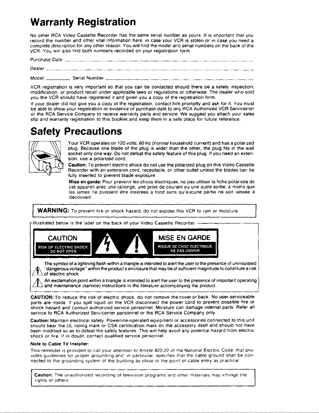
Your VCR operates on 120 volts, 60 Hz (normal household current) and has a polarized
plug. Because one blade of the plug is wider than the other, the plug fits in the wall
socket only one way. Do not defeat the safety feature of this plug, If you need an exten-
sion, use a polarized cord.
Caution: To prevent electric shock do not use the polarized plug on this Video Cassette
Recorder with an extension cord, receptacle, or other outlet unless the blades can be
fully inserted to prevent blade exposure.
Mise en garde: Pour prevenir les chocs electriques, ne pas utiliser la fiche polarisee de
cet appareil avec une rallonge, une prise de courant ou une autre sortie, _ moins que
les lames ne puissent etre inserees a fond sans qu'aucune pattie ne soit laissee
decouvert,
J WARNING: To tire shock hazard, do not this VCR to moisture J
-Illustrated below is the label on the back of your Video Cassette Recorder
The symbol of a lightning flash within a triangle is intended to alert the user to the presence of uninsulated
/_\ "dangerous voltage" within the product's enclosure that may be ofsufficient magnitude to constitute a risk
of electric shock
z_An exclamation point within a triangle is intended to alert the user to the presence of important operating
and maintenance (service) instructions in the literature accompanying the product
CAUTION: To reduce the risk of electric shock, do not remove the cover or back, No user-serviceable
parts are inside If you spill liquid on the VCR disconnect the power cord to prevent possible fire or
shock hazard and consult authorized service personnel Moisture can damage internal parts. Refer all
servtce to RCA Authorized Servicenter personnel or the RCA Service Company only.
Caution: Maintain electrical safety Powerline-operatert equipment or accessories Connected to this unit
should bear the UL listing mark or CSA certification mark on the accessory itself and should not have
been modified so as to defeat the safety features This will help avoid any potential hazard from electric
shock or fire if in doubt, contact qualified service personnel
Note to Cable TV Installer:
This reminder is provided to call your attention to Article 820-22of theNahonal Electric Code that pro-
wdes gu_dehnes for proper grounding and, _n particular, specifies that the cable ground shall be con-
netted to the grounding system of the building as close to the point of cable entry as practical
prevent
or
expose
rain or
I
m
rights of others
Caution: The unauthonzert recording of television programs and other materials may _nfrmge the I
I
I
Using This Manual
Congratulations on your choice of an RCA VCR. You have
selected a high-quality, precision-engineered instrument
designed to give you years of trouble-free video and audio
enjoyment.
To get the best performance from your new VCR, it is
important that you carefully read and follow the operating
instructions in this manual in the sequence in which they
are presented.
Should you experience a problem, please follow the
"Things to Check" near the end of this manual. The war-
ranty on the back cover describes what RCA will do for
you should your new VCR need service during the war-
ranty period. It also tells you how and from whom you
should request service.
nCJll
Copyright ® 1986, RCA Corporation
Contents
Warranty Registration .............. Inside Front Cover
Safety Precautions ................. Inside Front Cover
Installation
• Unpacking, Choosing Location .................... 2
• General Installation Information ................... 2
• Antenna Connections .......................... 3-4
• Cable-TV Connections .......................... 5-6
• TV Monitor/Receiver Connections ................. 7
• Stereo Amplifier Connections ..................... 8
What Your VCR Will Do ............................ 9
Basic Operation
• Basic Operating Controls and Displays ........... 10
• Inserting/Removing Cassettes ................... 10
• Turning on Your VCR for the First Time .......... 11
• Programming Active Channels into Tuner ......... 11
• Setting NORM/CATV Switch ..................... 11
• Setting TV to the VCR Channel .................. 11
• Setting the VCR/TV Switch ...................... 11
• Simplified Installation Checklist .................. 12
• Deleting Channels from Scan List ................ 12
• Adding Channels to Scan List .................... 12
Remote Control ................................... 13
Setting the Clock ................................. 14
First Recording and Playback ...................... 15
OperaUng Controls (Detailed) ................... 16-17
Special Effects
• Pause During Recording ......................... 17
• Recording Speeds for Special Effects ............ 17
• Pause for Stop-Action Playback .................. 17
• Frame Advance ................................. 17
• Slow Motion .................................... 17
• Picture Search .................................. 17
Special Features
• Memory Stop ................................... 18
• Tape Counter ................................... 18
• Electronic Program Indexing ..................... 18
• Indexed Playback ............................... 18
• Tracking Control ................................ 18
Audio System
• VHS Hi-Fi Sound ................................ 19
• Broadcast Stereo TV ............................ 19
• Second Audio Program .......................... 19
• Audio Dubbing .................................. 19
• Automatic Level Control ......................... 19
Video Cassettes .................................. 20
Quick-Reference Operatin 9 Guides
• Normal TV Viewing .............................. 21
• Recording With TV Off .......................... 21
• Recording and Viewing the Same Program ....... 21
• Recording and Viewing Different Programs ....... 22
• Basic PLayback ................................. 22
• Recording Broadcast Stereo/SAP ................ 23
• Recording TV/FM Simulcasts and Audio Only ..... 24
• Recording from Another VCR .................... 25
• Camera Recording .............................. 26
Express Recording ................................ 27
Programming the Timer ........................ 28-29
Timer Recording .................................. 30
Alternate Remote Control Units .................... 31
Cabinet Cleaning ................................. 32
Things To Check Before You Call for Service ....... 32
Subject Index ..................................... 33
Specifications ........................... Back Cover
RCA Ltmited Warranty .................... Back Cover
Installation
Unpacking
When you unpack your new VCR, be sure you have
removed all the accessories and information sheets. We
recommend that you save the packing materials and box
in case you ever need to ship or store your VCR.
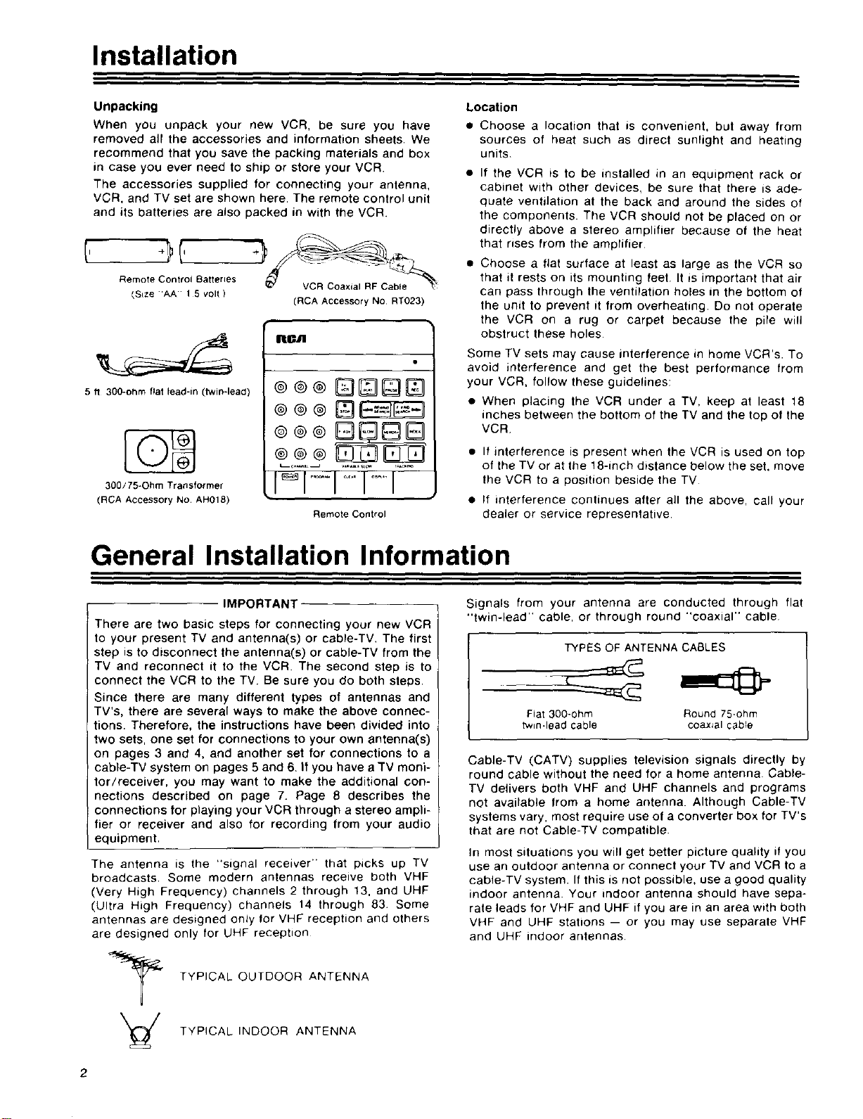
The accessories supplied for connecting your antenna,
VCR, and TV set are shown here. The remote control unit
and its batteries are also packed in with the VCR
Remote Control Batteries
_Size 1 5 volt )
_7 VCR Coaxial RF Cable _
(RCA Accessory NO RT023)
IIICA
5 fl 300-ohm flat lead-in (twin-lead)
®@@
300/75=Ohm Transformer
(RCA Accessory No AH018)
Remote Conlrol
Location
• Choose a location that is convenient, but away from
sources of heat such as direct sunlight and heating
units
• If the VCR is to be installed in an equipment rack or
cabinet with other devices, be sure that there is ade-
quate ventilation at the back and around the sides of
the components. The VCR should not be placed on or
directly above a stereo amplifier because of the heat
that rises from the amplifier
• Choose a fiat surface at least as large as the VCR so
that it rests on its mounting feet. It is important that air
can pass through the ventilation holes in the bottom of
the unit to prevent it from overheating. Do not operate
the VCR on a rug or carpet because the pile will
obstruct these holes
Some TV sets may cause interference in home VCR's. To
avoid interference and get the best performance from
your VCR, follow these guidelines:
• When placing the VCR under a TV, keep at least 18
inches between the bottom of the TV and the top of the
VCR
• If interference is present when the VCR is used on top
of the TV or at the 18-inch distance below the set, move
the VCR to a position beside the TV
• If interference continues after all the above, call your
dealer or service representative.
General Installation Information
IMPORTANT
There are two basic steps for connecting your new VCR
to your present TV and antenna(s) or cable-TV, The first
step is to disconnect the antenna(s) or cable-TV from the
TV and reconnect it to the VCR. The second step is to
connect the VCR to the TV Be sure you do both steps.
Since there are many different types of antennas and
TV's, there are several ways to make the above connec-
tions. Therefore, the instructions have been divided into
two sets, one set for connections to your own antenna(s)
on pages 3 and 4, and another set for connections to a
cable-TV system on pages 5 and 6, If you have a TV moni-
tor/receiver, you may want to make the additional con-
nections described on page 7. Page 8 describes the
connections for playing your VCR through a stereo ampli-
fier or receiver and also for recording from your audio
equipment.
The antenna is the "signal receiver" that picks up TV
broadcasts. Some modern antennas receive both VHF
(Very High Frequency) channels 2 through 13, and UHF
(Ultra High Frequency) channels 14 through 83 Some
antennas are designed only for VHF reception and others
are designed only for UHF reception
Signals from your antenna are conducted through flat
"twin-lead" cable, or through round "coaxial" cable
Cable-TV (CATV) supplies television signals directly by
round cable without the need for a home antenna. Cable-
TV delivers both VHF and UHF channels and programs
not available from a home antenna. Although Cable-TV
systems vary, most require use of a converter box for TV's
that are not Cable-TV compatible.
In most situations you will get better picture quality if you
use an outdoor antenna or connect your TV and VCR to a
cable-TV system. If this is not possible, use a good quality
indoor antenna Your indoor antenna should have sepa-
rate leads for VHF and UHF if you are in an area with both
VHF and UHF stations -- or you may use separate VHF
and UHF indoor antennas
TYPES OF ANTENNA CABLES
Fiat 300-ohm Round 75*ohm
twin-lead cable coaxial cable
TYPICAL OUTDOOR ANTENNA
TYPICAL INDOOR ANTENNA
2
Antenna Connections
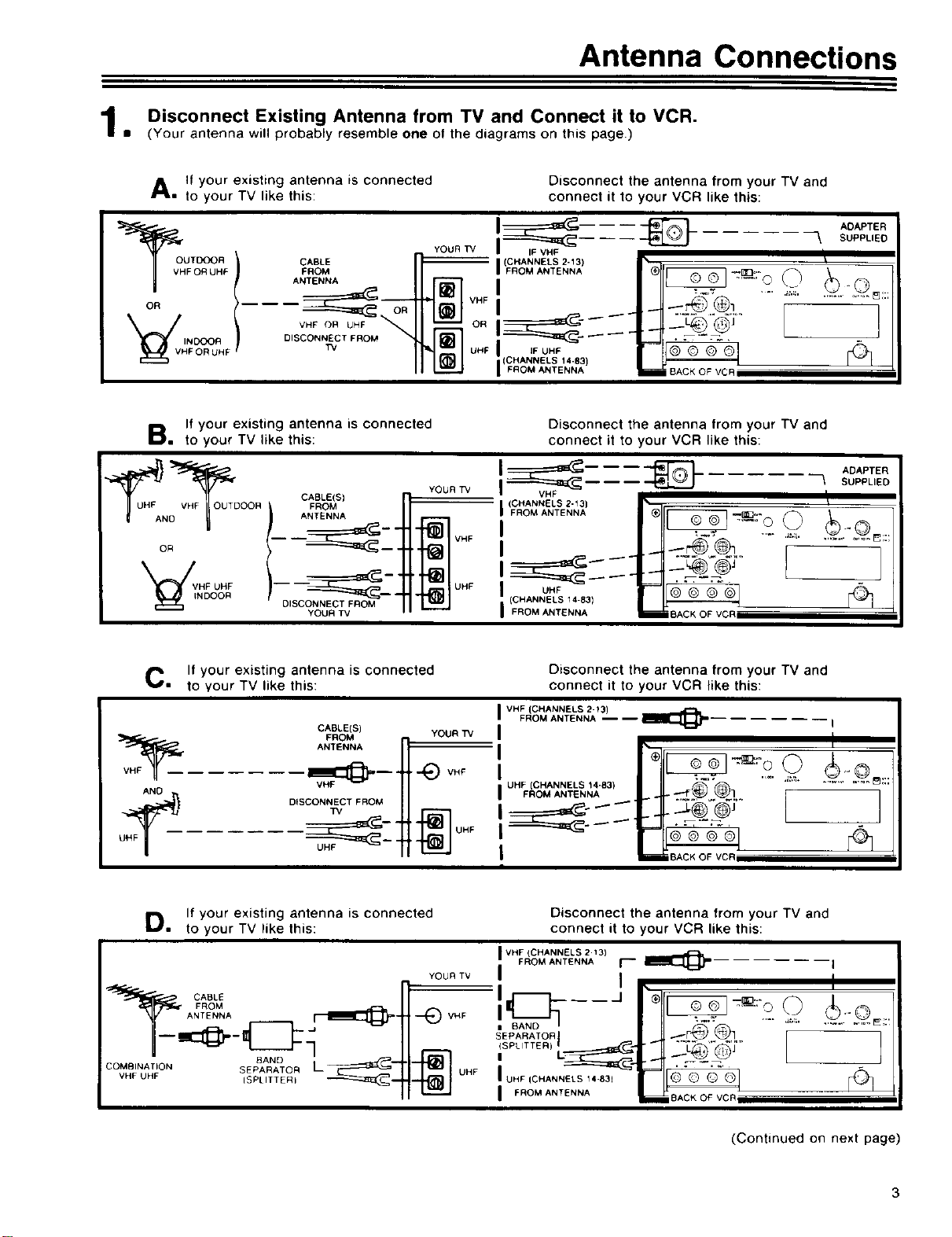
Disconnect Existing Antenna from TV and Connect it to VCR.
• (Your antenna will probably resemble one of the diagrams on this page.)
A, If your existing antenna is connected
to your TV like this:
FORUHF FROM
ANTENNA
OR t
HF OR UH F TV
If your existing antenna is connected
B, to your TV like this:
_UHFANo VHF_OUT D CABLE(S)
OR
VNHDFOUOHRF DISCONNECT FROM
YOUR TV
Disconnect the antenna from your TV and
connect it to your VCR like this:
YOOO
)CHANNELS 2-13)
"FI __- _-_..@L I
ll_ UHF )CHANNELS 14-83) BACK OF VCR
YOUR T_
IFReMANT,NNA_
Disconnect the antenna from your TV and
connect it to your VCR like this:
I_ _ ADAPTER-- -- -- _ SUPPLIED
VHF
(FCRHoANNAENLSE2"13) rL_l[_--_I_"_0 0
VHF
UHF
)C..NNELB,._,I--_
UHF "
FROM ANTENNA li_ BACK OF VCP
y l /
ADAPTER
SUPPLIED
C, If your existing antenna is connected
to your TV like this:
CABLE(S]
ANTENNA
VHF_ FROM
AND
UHF_ DISCONNEI_/CT FROM
D,, If your existing antenna is connected
to your TV like this:
COMBINAT)ON SEPARATO R
VHF UHF [SPLITTER)
BANDL_:
Disconnect the antenna from your TV and
connect it to your VCR like this:
VHF {CHANNELS 2-t3)
I
YOUR TV
"_ VHF
_] UHF
YOUR TV I , i
FROM ANTENNA -- -- _ ...... I
rfll ,.o..
UHF )CHANNELS 14-83) .... ' .....................
FROMANT_NNAL_.QL
I
Disconnect the antenna from your TV and
connect it to your VCR like this:
I VHF (CHANNELS 2 13)
FROM ANTENNA f--" _ I
S_PARATOR I ]]-r@ @_ r--_:-L_
)SPLITTER) I "<[" " ®'y
I
(Continued on next page)
3
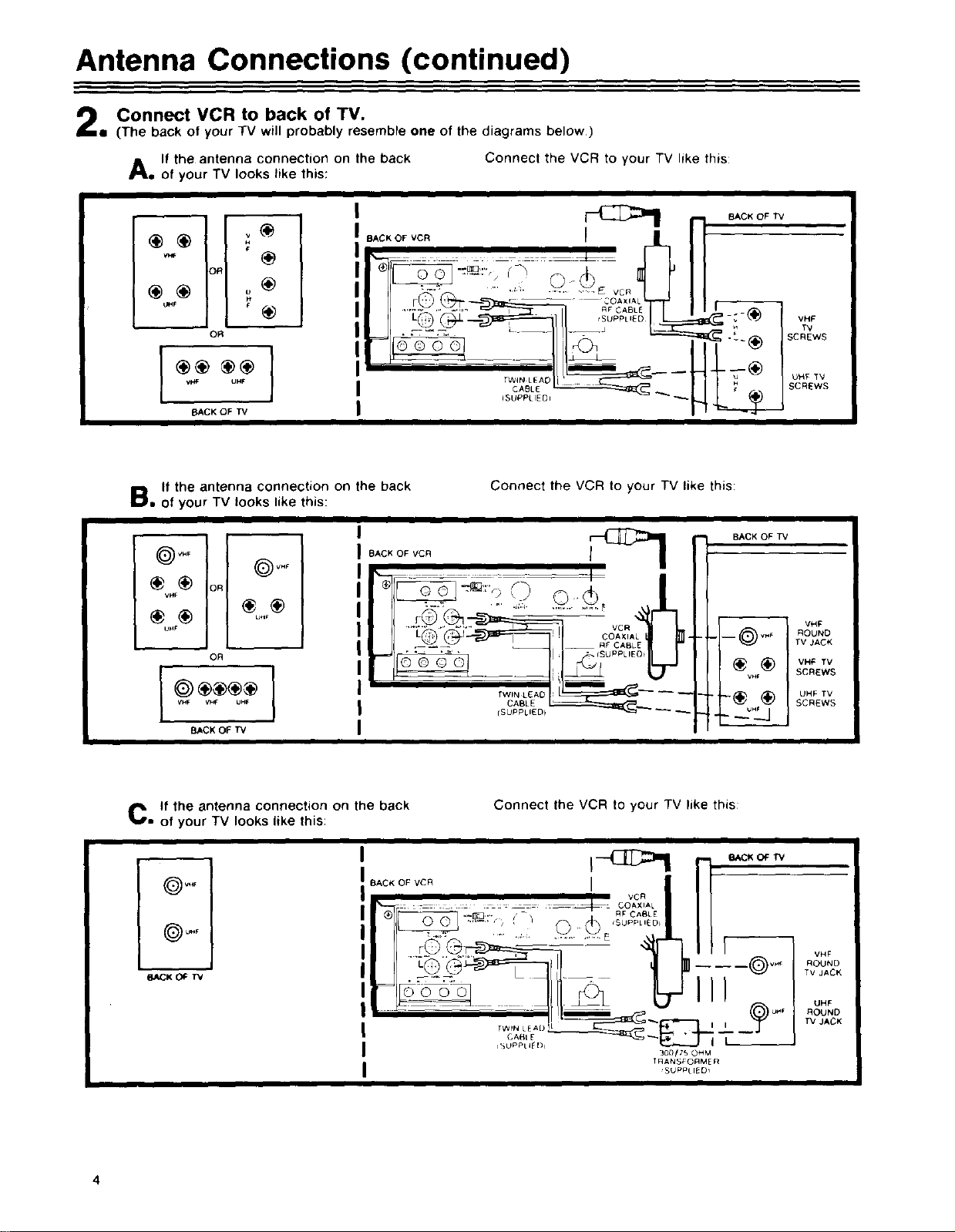
Antenna Connections (continued)
Connect VCR to back of TV.
• (The back of your TV will probably resemble one of the diagrams below)
A, If the antenna connection on the back
of your TV looks like this:
Connect the VCR to your TV like this:
v_
r
OR
OR
V_F UHF
BACK OF TV
B, If the antenna connection on the back
of your TV looks like this:
VHF
_® o_
VHF
°HF
OR
VHF
BACK OF VCR _ N BACK OF TV
BACK OF VCR I I
II
Connect the VCR to your TV like this:
BACK OF TV
/
vH_. w_- UHF
BACKOF TV
C= If the antenna connection on the back
of your TV looks like this:
I TWIN L[AD
I CABL E
I
I I--(:]:_:>1 rl BAc,OF,_
)VHF
(_U HF
_CK OIF W
BAc.o..cR ' vc .lII
i ii_ ; : ::: L : :: :: z: :_ _: COAX L I I I
I SUPPLIED _
(SUPPLIED_
I
Connect the VCR to your TV like this:
_[_3 .... , • RF CABLE
L ,,,
I'%WLI'pNpLL':[[_I o'
TF]ANS_ORME _
VHF
ROUND
TV JACK
UHF
ROUND
_/JACK
4
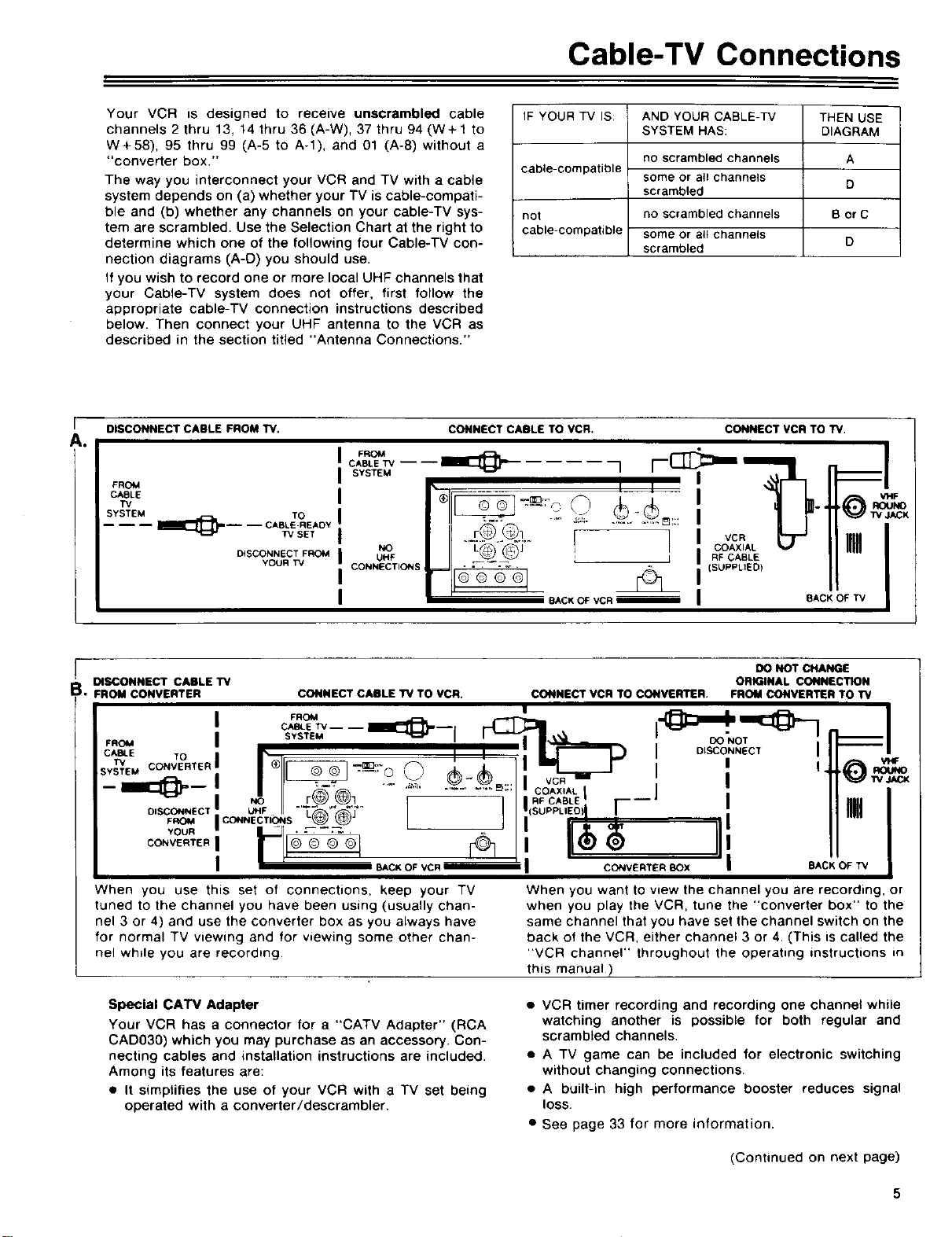
Cable-TV Connections
Your VCR is designed to receive unscrambled cable
channels 2 thru 13, 14 thru 36 (A-W), 37 thru 94 (W+I to
W+58), 95 thru 99 (A-5 to A-l), and 01 (A-8) without a
"converter box."
The way you interconnect your VCR and TV with a cable
system depends on (a) whether your TV is cable-compati-
ble and (b) whether any channels on your cable-TV sys-
tem are scrambled. Use the Selection Chart at the right to
determine which one of the following four Cable-TV con-
nection diagrams (A-D) you should use.
If you wish to record one or more local UHF channels that
your Cable-TV system does not offer, first follow the
appropriate cable-TV connection instructions described
below. Then connect your UHF antenna to the VCR as
described in the section titled "Antenna Connections."
r
DISCONNECT CABLE FROM TV,
A.
CABLE W----
F.OM
FROM
CAaLE
TV
SYSTEM TO
_----I_:{_----CABLE-READY
TVSET
DISCONNECT FROM
YOUR TV
SYSTEM
NO
UHF
CONNECTIONS
IF YOUR TV IS:
cable-compatible
not
cable-compatible
CONNECT CABLE TO VCR. CONNECT VCR TOW.
AND YOUR CABLE-TV
SYSTEM HAS:
no scrambled channels
some or all channels
scrambled
no scrambled channels
some or a(I channels
scrambled
THEN USE
L_t
I RF CABLE
(SUPPLIED)
_CK OF VCR mmmam
BACK OF TV
DIAGRAM
A
D
B orC
D
=1
_ w JACK
IIIIIL
DISCONNECT CABLE TV ORIGINAL CONNECTION
• FROM CONVERTER CONNECT CABLE W TO VCR. CONNECT VCR TO CONVERTER. FROM CONVERTER TO TV
DO NOT CHANGE
= .-7=. _ I
,.OM I s_S.E, i '_ I_ . oo'.o. , 11:===I
CAB4.E Tn I _ I I ; _ I DISCONNECT I I I i
SY_EMCONV_'RTE"I I ®II_ .,-__:ro _rh : _ II li=l I" I ' l_#_i .o_.o
-- ''-q=M- ....... NO r_ (_l '............. E_:::, _FCOAX'ALcABLEI -- J " |
co,vE.,E.I &$ ,
When you use this set of connections, keep your TV
tuned to the channel you have been using (usually chan-
nel 3 or 4) and use the converter box as you always have
for normal TV viewing and for viewing some other chan-
nel while you are recording
Special CATV Adapter
Your VCR has a connector for a "CATV Adapter" (RCA
CADO30) which you may purchase as an accessory. Con-
necting cables and installation instructions are included.
Among its features are:
• It simplifies the use of your VCR with a TV set being
operated with a converter/descrambler.
I | II_-_'_ _ _.__ i vc.-1"--" I It "_W_c,x
",1/ I 'l'(soo. ,EO,r- ! II,m
FROM | CONNECTIONS_ _ I ] I I ' ' ' I I I --"
,ou° I II. II
| I ' BACK OF VCR m I CONVERTER BOx | BACK OF TV
When you want to view the channel you are recording, or
when you play the VCR, tune the "converter box" to the
same channel that you have set the channel switch on the
back of the VCR. either channel 3 or 4. (This is called the
"VCR channel" throughout the operating instructions in
this manual)
• VCR timer recording and recording one channel while
watching another is possible for both regular and
scrambled channels.
• A TV game can be included for electronic switching
without changing connections.
• A built-in high performance booster reduces signal
lOSS.
• See page 33 for more information.
I
(Continued on next page)
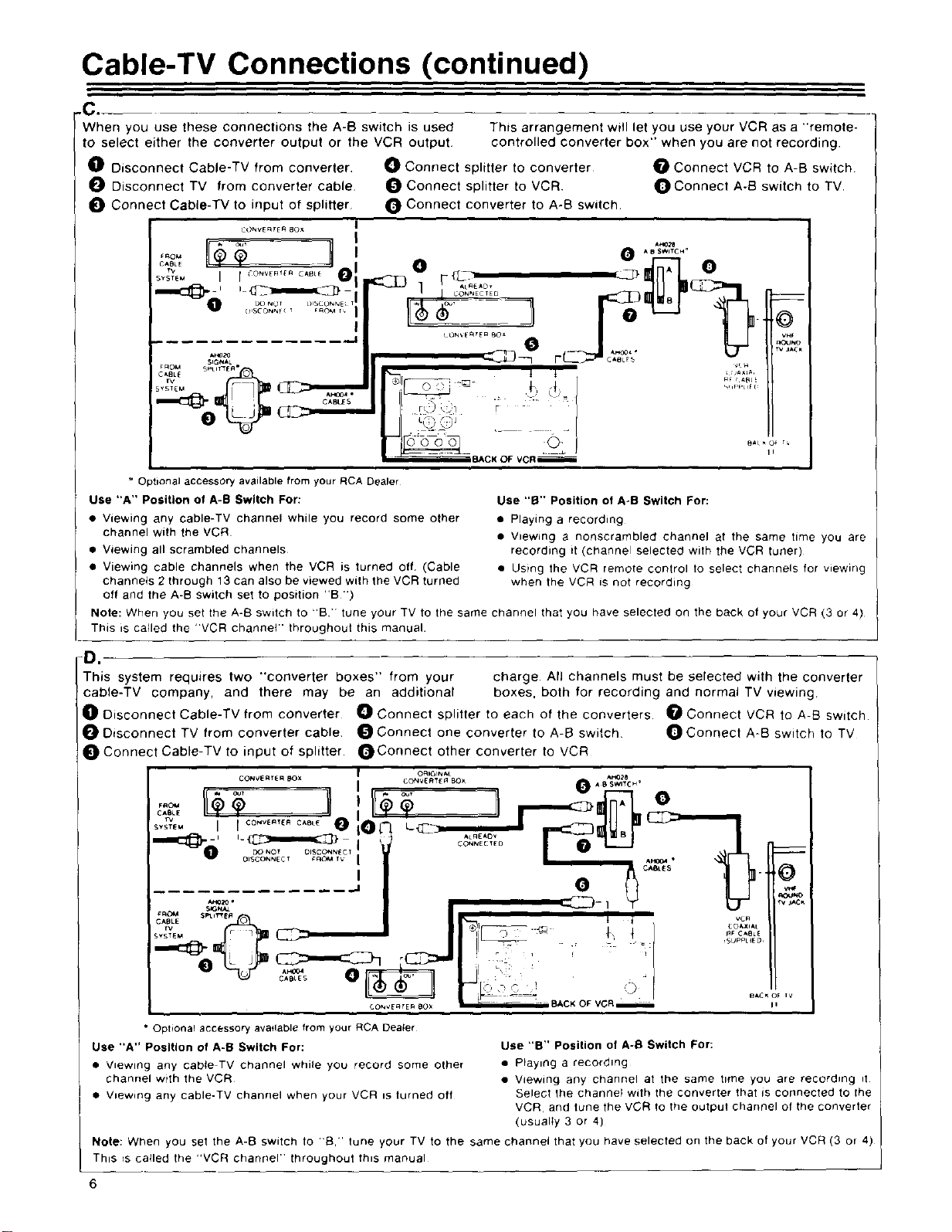
Cable-TV Connections (continued)
-C.
When you use these connections the A-B switch is used
to select either the converter output or the VCR output
0 Disconnect Cable-TV from converter.
O Disconnect TV from converter cable
Connect Cable-TV to input of splitter
C<)NVE RF[ R 8Ox |
Connect splitter to converter O Connect VCR to A-B switch
Connect splitter to VCR O Connect A-B switch to TV
Connect converter to A-B switch
This arrangement will let you use your VCR as a "remote-
controlled converter box" when you are not recording.
AH02e
• OSWITCH"
o o
0 ...._%_,_, "%'_'_'1
vH_
RO_JNO
r_ jaC_
_ROM SpUr"EA
c_E
= Optional accessory availablefrom your RCA Dealer
Use "A" Position of A-B Switch For:
• Viewing any cable-TV channel while you record some other
channel with the VCR
• Viewing all scrambled channels
• Viewing cable channels when the VCR is turned off (Cable
channels 2 through 13 can also be viewed with the VCR turned
off and the A-B switch set to position "B ")
Note: When you set the A-B switch to -Bi' tune your TV to the same channel that you have selected on the back of your VCR (3 or 4)
This is called the "VCR channel" throughout this manual.
S IG_A •
CABkE$
II
Use "B" Position of A-B Switch For:
• Playing a recording
• Viewing a nonscrambled channel at the same time you are
recording it (channel selected with the VCR tuner)
• Using the VCR remote control to select channels for wew_ng
when the VCR is not recording
D,
This system requires two "converter boxes" from your charge All channels must be selected with the converter
cable-TV company, and there may be an additional boxes, both for recording and normal TV viewing
Disconnect Cable-TV from converter Oconnect splitter to each of the converters OConnect VCR to A-B switch
Disconnect TV from converter cable O Connect one converter to A-B switch O Connect A-B switch to TV
Connect Cable-TV to input of splitter _Connect other converter to VCR
CONVE_T[_ _OX
c_e
s_steu I I co_v_te_ C_oue
O_JGINAL
.... £RT_ BOX _ 8 _W12/_ H '
I - . F'q
0
v_
Y tT
CO_Ve_E_ eOX -- BACK OF VCRm I,
• Optional accessory available from your RCA Dea_er
Use "A" Position of A-B Switch For:
• V_ewmg any cabte TV channel while you record some other
channel with the VCR
• V_ewing any cable-TV channel when your VCR _s turned oft
Note: When you set the A-B switch to 'B.' tune your TV to the same channel that you have selected on the back of your VCR(3 or 4)
I This =scalled the "VCR channel" throughout this manual
6
Use "B" Position of A-I_ Switch For:
• Playing a recordmg
• Viewing any channel at the same time you are record=ng =t
Select the channel with the converter that is connected to the
VCR, and tune the VCR to the output channel of the converter
(usually 3 or 4)
TV Monitor/Receiver Connections
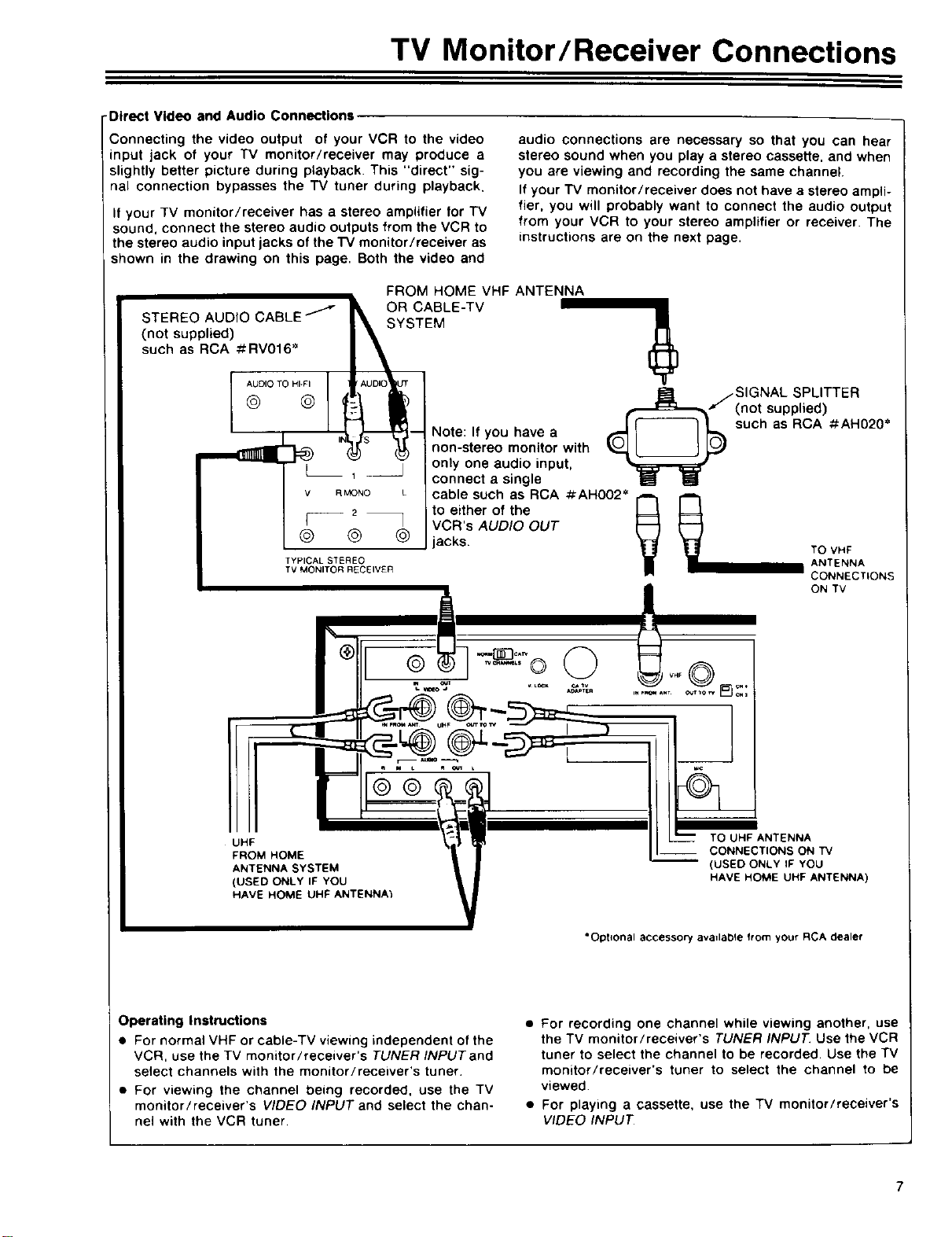
-Direct Video and Audio Connections
Connecting the video output of your VCR to the video
input jack of your TV monitor/receiver may produce a
slightly better picture during playback. This "direct" sig-
nal connection bypasses the TV tuner during playback.
If your TV monitor/receiver has a stereo amplifier for TV
sound, connect the stereo audio outputs from the VCR to
the stereo audio input jacks of the TV monitor/receiver as
shown in the drawing on this page. Both the video and
FROM HOME VHF ANTENNA
STEREO AUDIO CABLE /
(not supplied)
such as RCA #RV016 _
OR ABLE-TV
audio connections are necessary so that you can hear
stereo sound when you play a stereo cassette, and when
you are viewing and recording the same channel.
If your TV monitor/receiver does not have a stereo ampli-
fier, you will probably want to connect the audio output
from your VCR to your stereo amplifier or receiver. The
instructions are on the next page.
@ @
I AUDI O TO HI-El !
r _.,j-- Note: If you have a
lh
_s (._ non-stereo monitor with
t
1 connect a single
v
_MONO L cable such as RCA #AHO02 _
2 to either of the
I--
@
@ @ acks.
TYPICAL STEREO
TV MONITOR RECEIVER
UHF
FROM HOME
ANTENNA SYSTEM
(USED ONLYIF YOU
HAVE HOME UHF ANTENNA}
TEM
j only one audio input,
VCR's AUDIO OUT
SIGNAL SPLITTER
f (not supplied)
such as RCA #AH02O*
ANTENNA
CONNECTIONS
ON TV
TO UHF ANTENNA
CONNECTIONS ON TV
-- (USED ONLYIF YOU
HAVE HOME UHF ANTENNA)
Operating Instructions
• For normal VHF or cable-TV viewing independent of the
VCR, use the TV monitor/receiver's TUNER INPUTand
select channels with the monitor/receiver's tuner.
• For viewing the channel being recorded, use the TV
monitor/receiver's VIDEO INPUT and select the chan-
nel with the VCR tuner.
"Optional accessor-/ avadable from your RCA dealer
• For recording one channel while viewing another, use
the TV monitor/receiver's TUNER INPUT. Use the VCR
tuner to select the channel to be recorded. Use the TV
monitor/receiver's tuner to select the channel to be
viewed
• For playing a cassette, use the TV monitor/receiver's
VIDEO INPUT
7
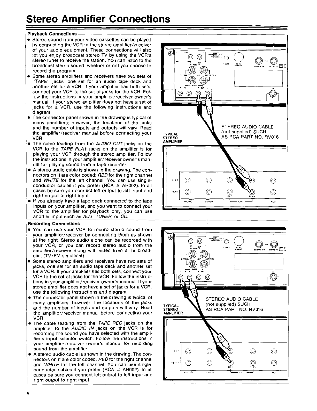
Stereo Amplifier Connections
Playback Connections
• Stereo sound from your video cassettes can be played
by connecting the VCR to the stereo amplifier/receiver
of your audio equipment. These connections will also
let you enjoy broadcast stereo TV by using the VCR's
stereo tuner to receive the station. You can listen to the
broadcast stereo sound, whether or not you choose to
record the program.
• Some stereo amplifiers and receivers have two sets of
"TAPE" jacks, one set for an audio tape deck and
another set for a VCR. If your amplifier has both sets,
connect your VCR to the set of jacks for the VCR. Fol-
low the instructions in your amplifier/receiver owner's
manual. If your stereo amplifier does not have a set of
jacks for a VCR, use the following instructions and
diagram.
• The connector panel shown in the drawing is typical of
many amplifiers; however, the locations of the jacks
and the number of inputs and outputs will vary. Read
the ampfifier/receiver manual before connecting your
VCR.
• The cable leading from the AUDIO OUT jacks on the
VCR to the TAPE PLAY jacks on the amplifier is for
playing your VCR through the stereo amplifier. Follow
the instructions in your amplifier/receiver owner's man-
ual for playing sound from a tape recorder.
• A stereo audio cable is shown in the drawing. The con-
nectors on it are color coded: RED for the right channel
and WHITE for the left channel. You can use single-
conductor cables if you prefer (RCA ._ AH002). In all
cases be sure you connect left output to left input and
right output to right input.
• If you already have a tape deck connected to the tape
inputs on your amplifier, and you want to connect your
VCR to the amplifier for playback only, you can use
another input such as AUX, TUNER, or CD.
Recording Connections
• You can use your VCR to record- stereo sound from
your amplifier/receiver by connecting them as shown
at the right. Stereo audio alone can be recorded with
your VCR, or you can record stereo audio from the
amplifier/receiver along with video from a TV broad-
cast (TV/FM simulcast).
• Some stereo amplifiers and receivers have two sets of
jacks, one set for an audio tape deck and another set
for a VCR. If your amplifier has both sets, connect your
VCR to the set of jacks for the VCR. Follow the instruc-
tions in your amplifier/receiver owner's manual. If your
stereo amplifier does not have a set of jacks for a VCR,
use the following instructions and diagram.
• The connector panel shown in the drawing is typical of
many amplifiers; however, the locations of the jacks
and the number of inputs and outputs will vary. Read
the amplifier/receiver manual before connecting your
VCR,
• The cable leading from the TAPE REC jacks on the
amplifier to the AUDIO IN jacks on the VCR is for
recording the sound you have selected with the ampli-
fier's input selector switch. Follow the instructions in
your amplifier/receiver owner's manual for recording
sound from the amplifier.
A stereo audio cable is shown in the drawing. The con-
nectors on it are color coded: RED for the right channel
and WHITE for the left channel. You can use single-
conductor cables if you prefer (RCA _ AH002). In all
cases be sure you connect left output to left input and
right output to right input.
®!
II
TYPICAL
STEREO
AMPLIFIER
®
TYPIC
STEREO
AMPLIFIER
© @ J--.r_o,_
r@@1
t
©
©
PHON@ _U_ER
..... ©Q
r@@l
_,_ UM_ OUTmW
STEREO AUDIO CABLE
(not supplied) SUCH
AS RCA PART NO. RV016
©
©
PHQNO
CA_
STEREO AUDIO CABLE
!_A(not supplied) SUCH
_EC PlAY @
,D_PT
HCC
....... o_ _ _
__PARTNO. RV016
VHF O
©
What Your VCR Will Do
Broadcast/Cable Frequency-Synthesis Tuner
Provides accurate selection of VHF/UHF TV channels or
up to 99 unscrambled cable channels. _ Quartz-controlled
electronics automatically lock the system onto the signal,
eliminating the need for fine tuning. Bright, easy-to-read
channel display.
"'Local systems may vary; check your cable company's
compatibility requirements.
Auto Programming
Preset available channels into VCR's electronic scan
memory at the touch of a single button. Eliminates cum-
bersome manual programming steps. After automatic pro-
gramming, channels can be selected by remote control
scanning -- either up or down. Add and Erase buttons
also are included for tailoring memory scan list to per-
sonal preference.
Broadcast Stereo Recording Capability with Bilingual
Audio Channel Reception (SAP)
Receive and record stereo sound from BTSC stereo TV
broadcasts, where available -- no modification or special
equipment is required. External stereo system or compati-
ble stereo TV required for stereo playback.
Also lets you record broadcast stereo while at the same
time recording the bilingual (SAP) channel, where avail-
able. Choose either standard or bilingual channel on
playback.
8-Hour Recording Time
Up to eight hours of uninterrupted record/playback time
are available in SLP mode with the RCA T-160 cassette.
During VHS Hi-Fi recording, that's comparable to ten or
more LP albums -- long enough to preserve hours of
music on a single tape without the need to change sides.
Standard Play (SP) and Long Play also are included to
ensure compatibility with all VHS-format tapes. VCR auto-
matically selects correct playback speed. LED indicators
signal tape speed.
VHS HI-FI Stereo
VHS Hi-Fi is a technological breakthrough that delivers
amazingly lifelike high fidelity stereo reproduction at all
three tape speeds with a dynamic range of more than 80
dB. (Conventional VCR's, by comparison, approach only
45-55 dB.) The secret is in the headwheel, which contains
two audio heads in addition to the video heads. Audio sig-
nals therefore are recorded at the same speed as video
signals -- a rate over a hundred times faster than conven-
tional audio recording. As a result, playback audio
approaches the quality of advanced digital audio.
Plays all standard prerecorded VHS tapes, whether stereo
or mono. Stereo audio outputs permit hook-up to an
external audio system or stereo TV. Stereo audio inputs
make Hi-Fi recordings from an external system possible at
home -- even without a video signal. Automatic level con-
trol (ALC) self-adjusts recording levels. Also features
right/left slide controls and illuminated peak indicators
for manual recording level adjustments.
Sound-with-Sound Audio Dub
Without affecting the Hi-Fi soundtrack, new audio can be
recorded onto the linear sound track of a previously rec-
orded cassette, erasing original linear audio. Optional
microphone or external audio system required. On play-
back, Hi-Fi track, linear track, or mix of both may be
chosen.
VHS HQ Picture Quality
This VCR incorporates VHS HQ (High Quality) circuitry for
improved picture quality. It is fully compatible with earlier
VHS VCR's.
Infrared Remote Control
Provides wireless VCR control from the comfort of an
easy chair. This VCR can also be operated with an RCA
Digital Command remote control and integrated into a
unified RCA audio/video system.
Remote Programming with On-Screen Display
With RCA's advanced remote control, all VCR timer pro-
gramming can be done from across the room. At the
touch of a button, simple easy-to-follow instructions
appear on TV screen to guide the viewer through each
programming sequence. Built-in computer memory can
be preset up to a year in advance to record as many as
eight programs automatically. Backup circuitry retains
programming instructions to prevent VCR memory loss in
case of brief power interruptions.
Delayed-Start Express Recording (XPR)
Two touch-buttons permit automatic timer recording with-
out the need for numerous programming steps. Just enter
starting time and length of desired program up to 24
hours before it airs. VCR will turn on at the correct time,
record the program and automatically shut off.
On-Screen Display Graphics
Vivid display appears on TV screen to provide visual con-
firmation of commands to VCR. Includes day/date, time,
channel, as well as on-screen tape counter to indicate rel-
ative position of programs on cassette. Counter memory
automatically stops tape at desired point during rewind or
fast forward.
"Field-Still" Video System with Jitter-Free Special
Effects (SP and SLP modes)
Sophisticated 5-head record/playback system with jitter-
free "field-still" video performance provides these special
effects in SP and SLP modes: Forward and Reverse
Search; Stop Action; Frame Advance; Variable Speed
Slow Motion.
Electronic Program Indexing
Simplifies finding start of recorded programs by automati-
cally encoding an electronic signal on the tape at begin-
ning of each new recording. During Fast Forward or
Rewind, the VCR will stop at each encoded signal, pre-
view a brief segment in Play mode and continue to next
signal. When desired point is reached, simply press PLAY
for normal viewing.
Automatic Rewind
Cassette is rewound automatically when end of tape is
reached. If VCR is turned off during rewind, it will finish
rewinding the cassette before shutting off. (To prevent
accidental erasures, Auto Rewind is not operative in
"Timer" mode.)
Scene Transition Stabilizer
Minimizes picture break-up that can occur when pause
control is used during recording. Result is smooth transi-
tion between taped segments.
Headphone Jack
Optional headphones can be plugged into VCR for private
stereo listening during recording or playback,
Unswitched AC Outlet
Power additional audio or video components (maximum
300 watts) directly from the VCR Components plugged
into outlet operate regardless of whether VCR is on or off.
Helps minimize cords at wall outlet. 9
 Loading...