

Page 1
PH
O
N
ES
O
PEN
/C
LO
SE
D
ISC
SKIP
P
R
O
G
R
E
S
S
IV
E
S
C
A
N
S
O
U
N
D
M
O
D
E
SO
U
RC
E
VO
LU
M
E
D
igital
S
ound
P
rocessor
mp3
C
D
-
R
/ R
W
C
O
M
P
A
T
IB
L
E
usermanual
RTD250
It is important to read this instruction book prior to using your new product for the first time.
Es importante leer este manual antes de usar por vez primera su euipo
.
Page 2
FCC Information
This device complies with Part 15 of the FCC Rules.
Operation is subject to the following two
conditions: (1) This device may not cause harmful
interference, and (2) this device must accept any
interference received, including interference that
may cause undesired operation.
This equipment has been tested and found to
comply with the limits for a Class B digital device,
pursuant to Part 15 of the FCC Rules. These limits
are designed to provide reasonable protection
against harmful interference in a residential
installation. This equipment generates, uses and
radiates radio frequency energy and, if not installed
and used in accordance with the instruction, may
cause harmful interference to radio communications. However, there is no guarantee that interference will not occur in a particular installation.
In accordance with FCC requirements, changes or
modifications not expressly approved by Thomson
Inc. could void the user’s authority to operate this
product.
This device generates and uses radio frequency (RF)
energy, and if not installed and used properly, this
equipment may cause interference to radio and
television reception.
If this equipment does cause interference to radio
or television reception (which you can determine by
unplugging the unit), try to correct the interference
by one or more of the following measures:
• Re-orient the receiving antenna (that is, the
antenna for the radio or television that is
"receiving" the interference).
• Move the unit away from the equipment that is
receiving interference.
• Plug the unit into a different wall outlet so that
the unit and the equipment receiving interference
are on different branch circuits.
If these measures do not eliminate the interference,
please consult your dealer or an experienced
radio/television technician for additional
suggestions.
Also, the Federal Communications Commission has
prepared a helpful booklet, "How To Identify and
Resolve Radio TV Interference Problems." This
booklet is available from the U.S. Government
Printing Office, Washington, DC 20402. Please specify stock number 004-000-00345-4 when ordering
copies.
This product complies with DHHS Rules 21 CFR
Subchapter J. Applicable at the date of
manufacture.
For Your Safety
The AC power plug is polarized (one blade is wider
than the other) and only fits into AC power outlets
one way. If the plug won’t go into the outlet completely, turn the plug over and try to insert it the
other way. If it still won’t fit, contact a qualified
electrician to change the outlet, or use a different
one. Do not attempt to bypass this safety feature.
For Your Records
In the event that service should
be required, you may need
both the model number and
the serial number. In the space
below, record the date and
place of purchase, and the serial number:
Model No.
Remote Control No. RCR311AAM1
Date of Purchase
Place of Purchase
Serial No.
Service Information
This product should be serviced only by those specially trained in appropriate servicing techniques.
For instructions on how to obtain service, refer to
the warranty included in this Guide.
Product
Dolby Digital 5DVD Audio video receiver
Brand: RCA
Model: RTD250
Electrical current consumption
120V
60Hz
180 Watts
IMPORTER
Comercializadora Thomson de Mexico, S.A. de C.V.
Miguel de Cervantes Saavedra No. 57
Col. Ampliación Granada
C.P. 11529 Mexico D.F.
Telefono: (55)25 81 53 20
RFC: CTM-980723-KS5
WARNING: TO PREVENT FIRE
OR ELECTRICAL
SHOCK HAZARD,
DO NOT EXPOSE THIS PRODUCT
TO RAIN OR MOISTURE.
SEE MARKING ON BOTTOM / BACK OF PRODUCT
CAUTION
RISK OF ELECTRIC SHOCK
DO NOT OPEN
THE EXCLAMATION
POINT WITHIN THE
TRIANGLE IS A
WARNING SIGN
ALERTING YOU OF
IMPORTANT
INSTRUCTIONS
A CCOMPANYING
THE PRODUCT.
THE LIGHTNING
FLASH AND ARROWHEAD WITHIN THE
TRIANGLE IS A
WARNING SIGN
ALERTING YOU OF
"DANGEROUS
VOLTAGE" INSIDE
THE PRODUCT.
CAUTION: TO REDUCE THE
RISK OF ELECTRIC SHOCK,
DO NOT REMOVE COVER
(OR BACK). NO USERSERVICEABLE PARTS INSIDE. REFER SERVICING
TO QUALIFIED SERVICE
PERSONNEL.
This Class B digital apparatus complies with Canadian
ICES-003.
Cet appareil numérique de la class B est conforme à la
norme du NMB-003 du Canada
Page 3

MusicMatch™ Software
RCA is among the first Consumer Electronics companies to have adopted the MP3 format, starting with the release of its mp3 player,
Lyra, into the market. (www.rca.com and www.lyrazone.com). RCA is proud of its initial success and has developed the competencies to
enlarge its offering to other products like Discman and this System. RCA thanks you for your purchase of this System which aims at giving
you tremendous pleasure while listening to your favorite music. In addition to this great System, RCA is proud to offer you the Music
Match CD-ROM, which will assist you in managing your mp3 music library!
The MusicMatch Jukebox
This music management software, to be installed on your PC, allows you to compress music files recorded from you audio CDs into mp3
format and stores them on your PC.
• It makes the search and download of Internet music easier,
• It allows for the management of compressed music and the creation of your own playlist,
• The Jukebox is a true audio player installed on your PC,
• It gives access to thousands of net radios available on the web today.
You can download music files encoded in mp3 from several Internet sites like www.mp3.com.
Playing mp3
• Use .mp3 as the extension when converting audio files into mp3 for saving onto CD-R(W) or CD-ROM, e.g. Rocky08.mp3. Do not use
any other extension e.g. .doc, .pdf.
• Do not use the .mp3 extension for other text or non-audio data files as this may result in serious malfunction and harmful noise interference.
Page 4

1
FCC Information
MusicMatch Software
Getting Started
Unpacking the DVD Receiver . . . . . . . . .2
Unpacking the Speakers . . . . . . . . . . . . .2
Inserting Batteries into Remote Control .3
Set Up and Maintenance of the
Receiver . . . . . . . . . . . . . . . . . . . . . . . . . .3
Protect your Components from
Overheating . . . . . . . . . . . . . . . . . . . . . . .3
Disc Information . . . . . . . . . . . . . . . . . . .3
Connecting to Audio-Visual
Components . . . . . . . . . . . . . . . . . . . . . .4
Digital Connection . . . . . . . . . . . . . . . . .5
Connecting Antennas . . . . . . . . . . . . . . .5
Connecting the Speakers . . . . . . . . . . . . .6
Connecting the Subwoofer . . . . . . . . . . .6
Positioning your Speaker . . . . . . . . . . . . .7
Front Speaker Placement . . . . . . . . . . . . .7
Preferred Surround Placement . . . . . . . .8
Advanced Surround Setting . . . . . . . . . .8
Test Tone / Channel Balance . . . . . . . . . .9
Using Headphones . . . . . . . . . . . . . . . . . .9
Factory Setting . . . . . . . . . . . . . . . . . . . . .9
Operating your Receiver
Receiver Controls . . . . . . . . . . . . . . . . . .10
Remote Control . . . . . . . . . . . . . . . . . . .11
Display . . . . . . . . . . . . . . . . . . . . . . . . . .12
Switching On/Off . . . . . . . . . . . . . . . . . .13
Selection of Audio/Video Source . . . . . .13
Using the Remote to Control Additional
Components . . . . . . . . . . . . . . . . . . . . . .14
Advanced Sound Control
Sound Enhancement Systems . . . . . . . .15
Fine Setting of Components . . . . . . . . .16
Fine Setting of the Speakers . . . . . . . . .17
Advanced Setting . . . . . . . . . . . . . . . . .17
DVD Player
Basic Playback Features . . . . . . . . . . . . .19
Quick Search . . . . . . . . . . . . . . . . . . . . .19
Freeze Frame and Frame Advance . . . .19
Slow Motion Playback (DVD only) . . . . .20
Progressive Scan . . . . . . . . . . . . . . . . . . .20
On-Screen Banner Display . . . . . . . . . . .20
Setup Menu . . . . . . . . . . . . . . . . . . . . . .25
CD / mp3 Player
mp3 Recommendations . . . . . . . . . . . . .30
Loading and Playing an Audio CD . . . .30
On-Screen Banner Display for CD
Playback . . . . . . . . . . . . . . . . . . . . . . . . .32
On-Screen Display for mp3 playback
. . . . . . . . . . . . . . . . . . . . . . . . . . . . .35-36
JPEG CD
On-Screen Display for JPEG CD . . . . . . .37
Radio
Operating the Radio . . . . . . . . . . . . .38-39
Troubleshooting Tips . . . . . . . .40-41
Care and Maintenance . . . . . . . . .42
Remote Codes
TV Codes . . . . . . . . . . . . . . . . . . . . . .43-44
Language Code . . . . . . . . . . . . . . .45
Limited Warranty
EN
Table of Content
Page 5
Getting Started
Unpacking the DVD Receiver
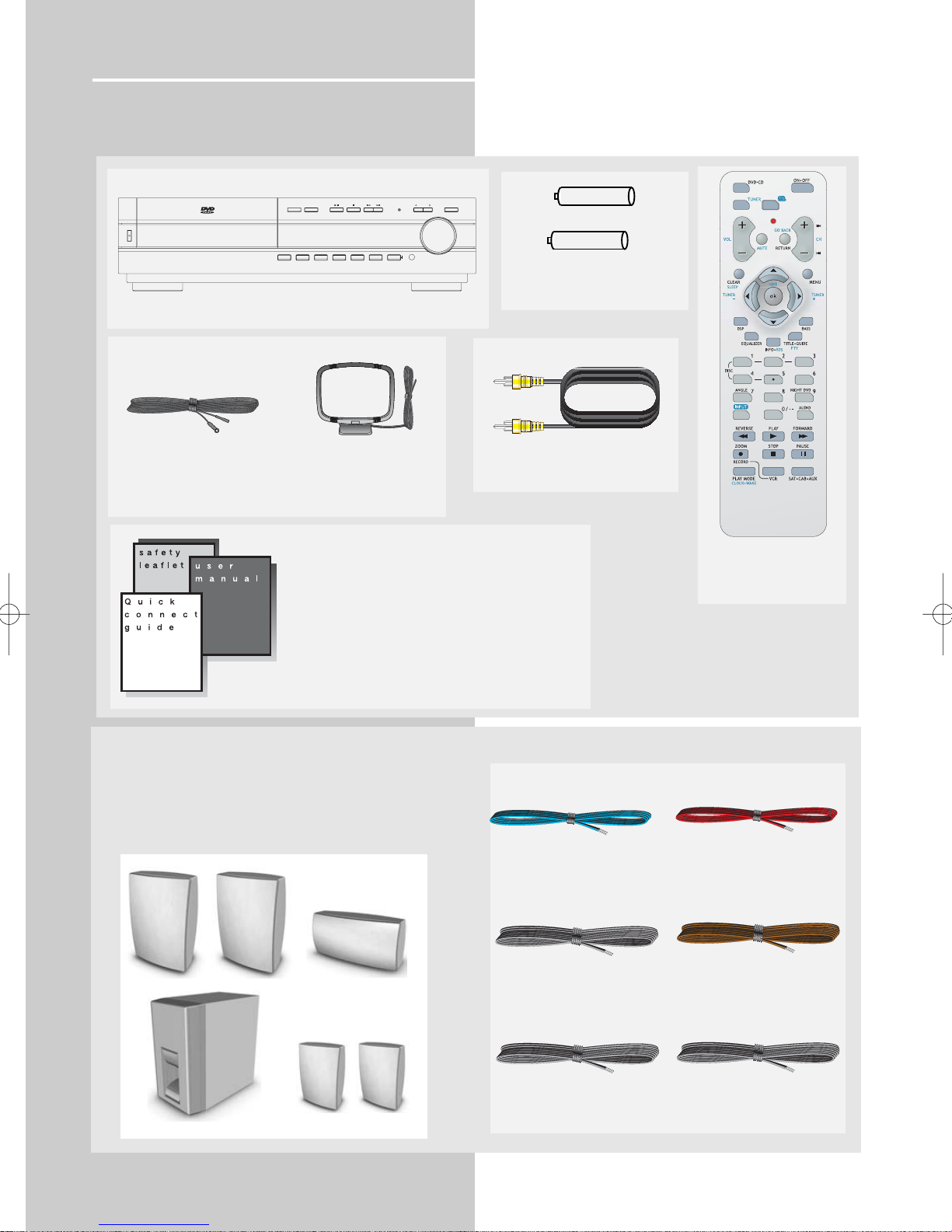
You should receive the following items:
2
One DVD receiver unit
One pair of “AAA”
batteries
One Pig-Tail
antenna wire
One external AM loop
antenna
one video cable (single wire)
with yellow connectors;
• one instruction book;
• one safety leaflet;
• one Quick Connection Guide
One RCA Universal
Remote Control
(RCR311AAM1)
Unpacking The Speakers
• one set of speakers including 1 set of left and right front
speakers, 1 centre speaker, 1 subwoofer and 1 set of left
and right rear speakers.
1 X white/black wire for
front left speaker
1 X purple/black wire
for subwoofer
1 X green/black wire
for center speaker
1 X red/black wire for
front right speaker
1 X blue/black wire for
rear left speaker
1 X gray/black wire for
rear right speaker
ON/STANDBY
5 DVD/CD CHANGER
DIGITAL SURROUND RECEIVER RTD250
OPEN/CLOSE DISC SKIP
BAND/APP REPEAT RANDOM PROGRAM DISPLAY TEST BASS/TRE
PROGRESSIVE
SOUND MODE
SCAN
SOURCE
VOLUME
+ -
+ -
PROG.
SCAN
PHONES
FRONT SPEAKERS
SUBWOOFER
CENTER SPEAKER
REAR SPEAKERS
(SURROUND SOUND)
Page 6
Getting Started
Inserting Batteries into Remote Control
Insert two AAA batteries according to the + and - signs on
the battery compartment. To use the remote control, point
it directly at your receiver.
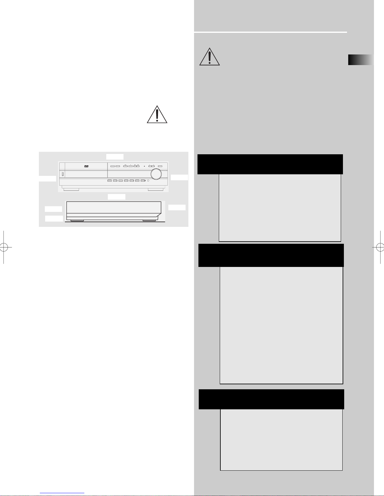
Set up and Maintenance of the Receiver
IMPORTANT NOTE
• Provide spaces for sufficient ventilation as indicated
below. If the space is insufficient, the unit may overheat
resulting in malfunction and shorter life time.
• Do not connect to the AC power cords until all connections are completed.
• Do not use your set immediately after transferring it from
a cold place to a warm place: there is risk of condensation.
• Do not expose your set to water and excessively high
temperatures.
• After having disconnected your set, clean the case with a
soft cloth, or with a slightly damp leather chamois. Never
use strong solvents.
Disc handling precaution:
• Do not touch the recorded surface.
• Do not use record cleaning sprays, solvent or anti-static
liquid.
• If the disc is dirty, clean it with a damp cloth and wipe
from the center out. Wipe in straight line and not in circular motion.
• Do not attach stickers, label on the disc.
• Store the disc in its case after playing.
Protect your Components from
Overheating
• Do not block ventilation holes in any component.
Arrange the components so that air can circulate freely.
• Do not stack components directly on top of each other.
• Allow adequate ventilation when placing your components in a stand.
• Place the receiver near the top shelf of the stand so
heated air rising from it will not affect other components.
Disc Information
EN
3
About CDR, CDRW, Audio mp3, Compact
Disk Audio (CDA), DVD Video, DVD Audio
This model is compatible to play CDR, CDRW,
Audio mp3, Compact Disk Audio (CDA), Video
Compact Disk (VCD) and DVD Audio, JPEG pictures.
While your disc player is compatible with the
largest number of discs possible, it cannot be guaranteed that you will be able to play discs which
might not be compatible with audio CD, VCD and
SVCD standards.
NOTES ON CD-R/RW DISC
This unit is compatible with CD-RW/ CD-R discs for
playback.
• Do not affix any type of labels to either side
(recordable or labeled side) of a CD-R/RW disc as
this may result in the unit malfunctioning.
• Do not load an unrecorded CD-R/RW disc into the
unit. This may take a longer time to read the disc.
• Playback capability for CD-RW discs may
vary due to variations in the quality of the
CD-RW disc and the recorder used to create
the disc.
Playback capability of CD-R, DVD-R and
rewritable discs, compatibility with this player depends on the recorder, the burning software and the disc used
10cm/4”
5cm/2”
10cm/4”
10cm/4”
10cm/4”
ATTENTION
This unit is incompatible with the following disc
formats:
DVD-ROM, DVD-RW, DVD+RW, DVD RAM, DVD-R,
CDV, SACD, DVD Audio (High resolution tracks).
Data part of CD Extra, disc with non standard
shape (e.g. heart), disc with region code different
from the one specified on the back of the unit.
Front
Rear
PROGRESSIVE
OPEN/CLOSE DISC SKIP
ON/STANDBY
5 DVD/CD CHANGER
DIGITAL SURROUND RECEIVER RTD250
BAND/APP REPEAT RANDOM PROGRAM DISPLAY TEST BASS/TRE
SOUND MODE
SOURCE
SCAN
VOLUME
PROG.
SCAN
PHONES
Page 7
Getting Started
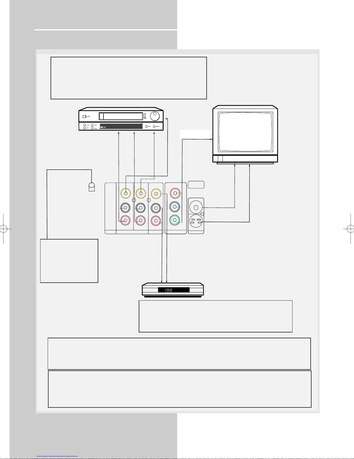
Connecting to Audio-Visual Components
4
(if available)
ANALOG INPUT
Alternatively, if you have no VCR or SAT, you can connect any other
compatible components like TAPE player, TV to your DVD receiver via
the VCR/SAT input.
- VCR audio/video out will have output signal in SAT, DVD/CD and
TUNER modes. When VCR (source) is selected, there will be no
audio/video signal from VCR audio/video out.
VCR
TO VIDEO IN (VCR)
TO VIDEO OUT (VCR)
IN
IN
IN
IN
SAT
TO AUDIO OUT (SAT)
DIGITAL
OPTICAL OUT
DIGITAL OUTPUT
Connect components
capable of recording
digital signals (e.g. MD,
CD recorder player)
equipped with a optical
input.
VIDEO
AUDIO
TO AUDIO IN (VCR)
OUT
L
R
OUT
VCR
TO AUDIO OUT (VCR)
COMPONENT IN (TV)
OUT
Cr
Cb
Y
COMPONENT
DVD ONLY
VIDEO OUT (SAT)
SAT
(If available)
MONITOR
OUT
OUT
S-VIDEO
DVD ONLY
TV
S-VIDEO IN (TV)
VIDEO IN (TV)
Component video output
Component video terminal provides the best connection for video. By separating the color information (Pb/Pr) and the
luminance signal (Y), the image is improved comparing with S-video or composite video connection (result may vary on
different TV / monitor). If your TV is equipped with these terminals (e.g. Y/Pb/Pr, Y/Cb/Cr, Y/B-Y/R-Y), use an appropriate
video cable (75 Ohm) and connect to the system. Make sure to match the terminal color.
Progressive Scan
- It is necessary to use component video connection to enjoy progressive scan.
- Connect to a TV that has 480P input terminal or compatible with copy guard system, else the image will not be displayed
properly.
- If progressive scan is ON, there will be no video signal output at composite video (VCR OUT), s-video and composite video
monitor output. (Please refer to page 20 for details of activating progressive scan function)
S-VIDEO
S-video provides a better connection for the video portion of the signal
than composite video (yellow color terminal). When connecting S-video
cable, a Composite video cable (yellow RCA connector) must also be
used. S-video will have video output for DVD playback only.
Page 8
Getting Started
EN
5
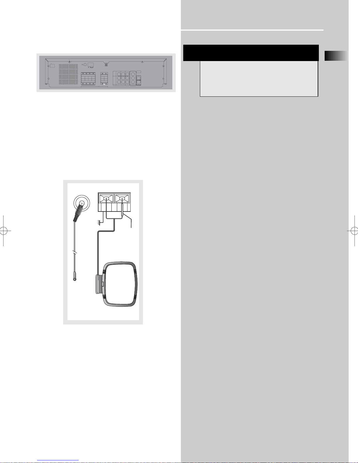
Connecting the Antennas
The AM and FM antennas connect to the AM and FM terminals on the system’s back panel.
They must be hooked up in order to receive clear reception.
AM Loop Antenna and FM Indoor Antenna
1. Uncoil the AM Antenna wire.
2. Press down on the Antenna tab to open the terminal.
Note: Make sure the white wire on the AM lop antenna is
inserted into the left terminal.
HINT
• For FM reception, extend antenna to its full
length and arrange the Antenna at different parts
of the room until the reception is optimized.
• For AM reception, rotate the antenna
horizontally to get better reception.
AC 120V/60Hz
FM
FRONT
R
R
REAR (6 Ω)
DIGITAL
OPTICAL OUT
AM LOOP
GND
CENTER (6 Ω)
(6 Ω)
L
L
SPEAKERS
OUT
VIDEO
L
AUDIO
R
(12 Ω)
OUT
SUB
MONITOR
OUT
IN
IN
OUT
Cr
OUT
Cb
Y
IN
IN
COMPONENT
S-VIDEO
SAT
VCR
DVD ONLY
DVD ONLY
GND
FM 75
Ω
AM LOOP
White
Page 9
Getting Started
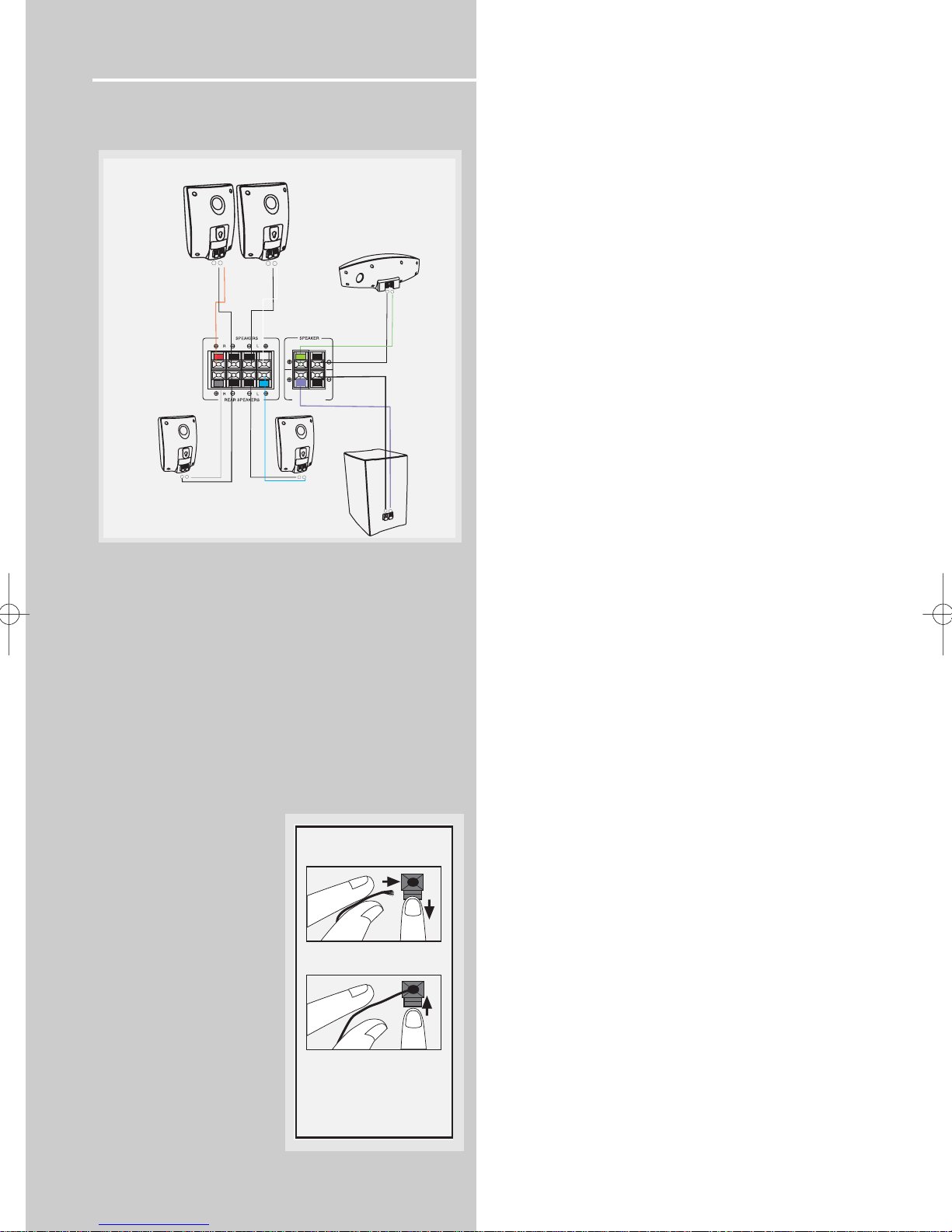
Connecting the Speakers
Speakers
There are 6 speakers equipped with the unit (2 front, 1 center, 2 rear, 1 subwoofer). In order to enjoy good surround
effects all six speakers need to be connected to the receiver
For better sound quality, center speaker, rear speakers and
Subwoofer should also be connected. Adding center and
rear speakers will enhance surround effects. Adding a
Subwoofer will increase bass response.
If you want to enjoy the full sound rangeuse the subwoofer
with the speakers to maintain adequate bass signal.
Speaker cords
1 for each speaker, is
needed for connection. Twist
the stripped ends of speaker
cord about 2/3 inch (15 mm).
Press down on the tab to
open the terminal and insert
the wire. Release tab to lock
wire in the terminal.
To ease speaker connections, the speaker cords and the terminals are color-coded.
• White/Black (Front Left Speaker),
• Red/Black (Front Right Speaker),
• Green/Black (Center Speaker)
• Blue/Black (Rear Left Speaker).
• Grey/Black (Rear Right Speaker).
• Purple/Black (Subwoofer)
Connect the speaker wire to the back of L, R front speakers
and to the corresponding color terminals on the rear of the
receiver. Do the same for center speaker, rear speakers and
the subwoofer.
Speaker Polarity
When connecting the speakers, make sure the polarities
(“+” speaker wire to “+” on the receiver) of speaker wires
and terminals are matched. If the cords are reversed, the
sound will be distorted and will lack bass (“out of phase”
effect).
Do not ground the output line, it will cause damage to the
speaker.
Connecting the Subwoofer
Connect the subwoofer with the speaker wire (purple/
black) provided.
6
Antenna and Speaker
Wire Connection
Push Speaker terminal tab
down to insert wire.
Release tab to lock wire in
the terminal.
NOTE: Make sure the insulation
is completely removed from the
ends of the Antenna and
speaker wires at all connection
points.
FRONT SPEAKERS
FRONT
LEFT
+
-
+
Black
Black
White
CENTER
SUB WOOFER
Gray
Black
Black
SPEAKER
Blue
REAR
-
RIGHT
-
Red
REAR
-
+
REAR SPEAKERS (SURROUND SOUND)
CENTER
SPEAKER
-
+
Green
Black
Black
Purple
SUB WOOFER
+
-
+
Page 10
Getting Started
Positioning your speaker
1 Left, Right (Front Speakers)
They carry primarily music and sound effects.
2 Center
In surround mode, the center speaker carries much of the
dialogue as well as music and effects. It should be set
between the left and right speakers.
3 Surround (Rear Speakers)
Their overall sound balance should be as close as possible
to the front speakers. Proper placement is vital to establish
an evenly distributed sound field.
Subwoofer
A subwoofer is designed to reproduce powerful low bass
effects (explosions, the rumble of spaceships, etc.) which
dramatically heightens involvement with the action on the
screen. It is therefore recommended to connect subwoofers when small speakers are used.
Magnetic shielding
Speakers placed less than two feet from the TV set must be
magnetically shielded in order to prevent picture distortion. Front and center speakers provided with this unit are
magnetically shielded to protect your TV set.
It is not recommended to place the rear speakers near the
TV set.
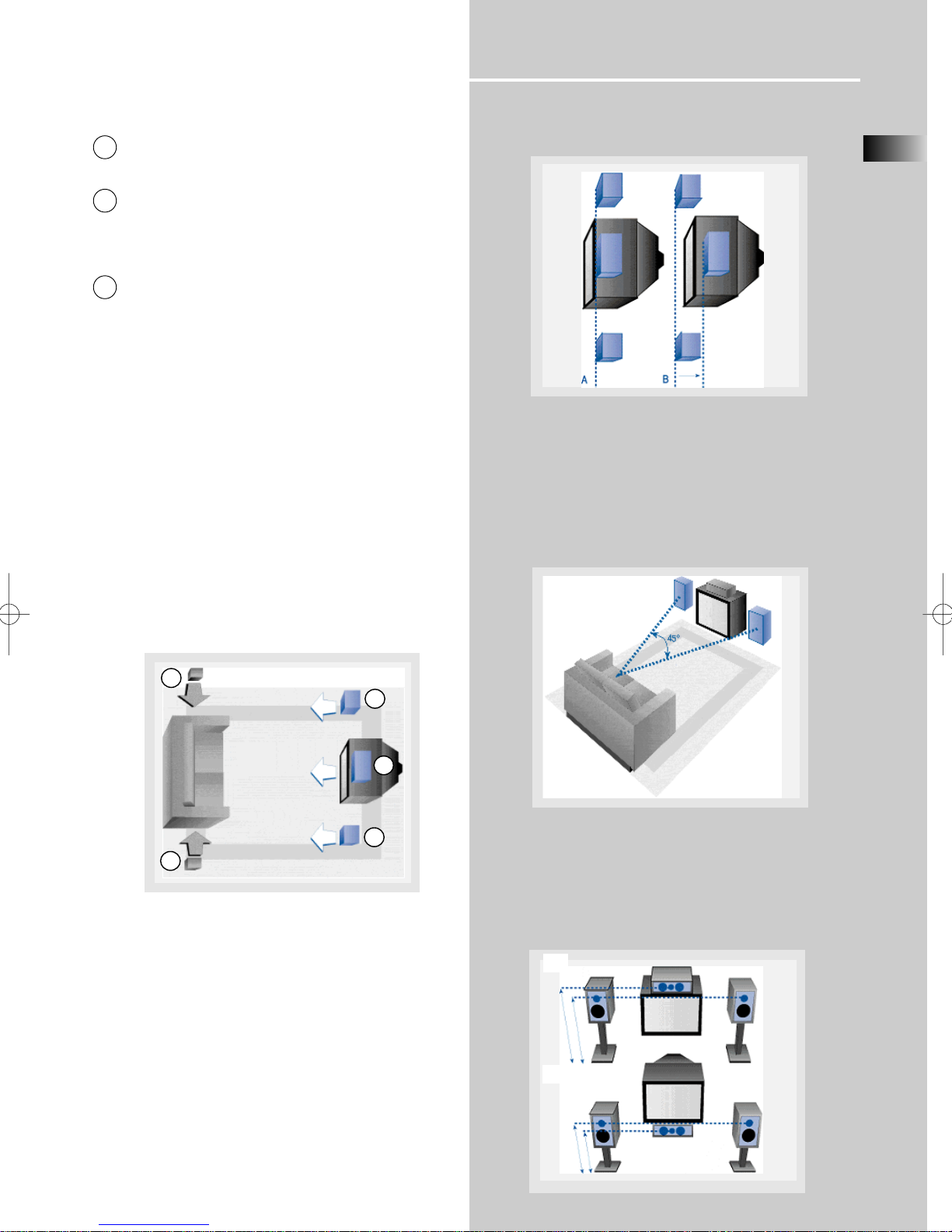
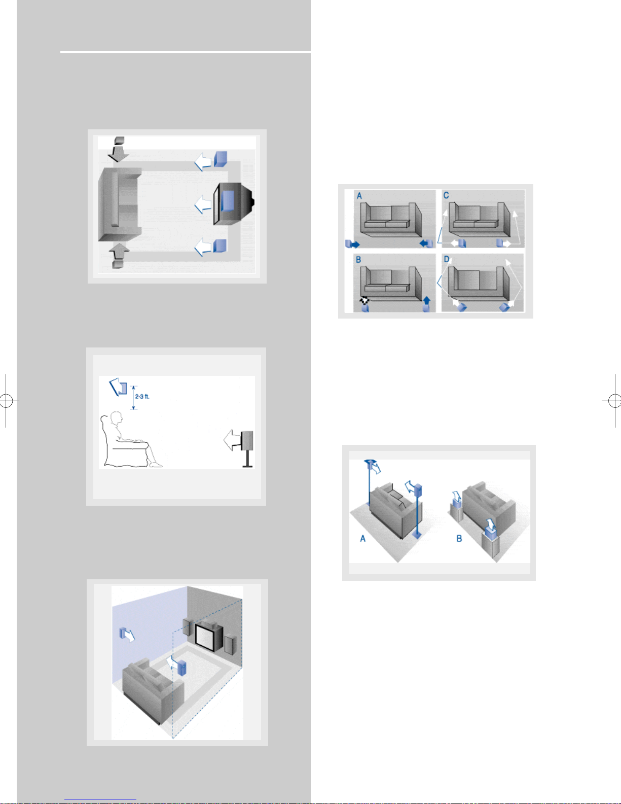
Front Speaker Placement
Even if you can't duplicate this ideal home theater setup
exactly, the suggestions for speaker placement that follow
will help you get good results.
Alignment
Align the center speaker evenly with (A), or slightly behind
(B), the left and right speakers, but not ahead of them.
Advanced Setting
Angle
Placing the left and right speakers to form a 45-degree
angle with your favorite viewing position will duplicate the
soundtrack mixer's perspective.
Height
The mid- and high-frequency drivers of the three front
speakers should be as close as possible to the same height.
This often requires placing the center speaker directly atop
(A) or beneath (B) the TV set.
EN
7
1
1
2
3
3
A
B
Courtesy Dolby Laboratories
Courtesy Dolby Laboratories
Courtesy Dolby Laboratories
Courtesy Dolby Laboratories
Page 11
Getting Started
Preferred surround placement
Location
If possible, place surround speakers to either side of the listening area, not behind it.
Height
If space permits, install surrounds 2-3 feet above viewers.
This helps to minimize localization effects.
Aiming
Aiming surrounds straight across the room, not down at
viewers, helps create a more open, spacious surround sound
field.
Advanced Setting
Alternative Surround Placement
Rear wall
If rear wall mounting is the only choice, aim the speakers at
each other (A), towards the front (B) or even towards the
sidewalls (C, D). Experiment with placement until surround
sounds seem to envelop you, rather than coming from
behind you.
No adjacent walls
Surrounds can go on stands facing each other to approximate the preferred sidewall mounting (A), or to the sides
or rear of the viewing area aimed upwards. In the latter
case, they can go right on the floor, or preferably, a few
feet off the floor such as on end tables (B).
8
Courtesy Dolby Laboratories
Courtesy Dolby Laboratories
Courtesy Dolby Laboratories
Courtesy Dolby Laboratories
Courtesy Dolby Laboratories
Page 12
Getting Started
EN
9
Test Tone / Channel balance
Channel balance
Your receiver is equipped with a test signal generator for
balancing the channels. As the signal "travels" from channel to channel, adjust the level controls until each channel
plays at the same loudness level.
Please refer to “Fine setting your speaker” section for more
details.
Level adjustment & surround channel level
expectation
Even though you adjust the surround channel to be as loud
as the others on the test signal, you'll find that on actual
program material the surround channel is usually much
lower than the front. Don't be tempted to readjust the surround level; program producers use surround mostly for
subtle atmosphereics and ambience, and only rarely for
special effects. A good surround mix doesn't call attention
to itself; if it did, it would soon become distracting.
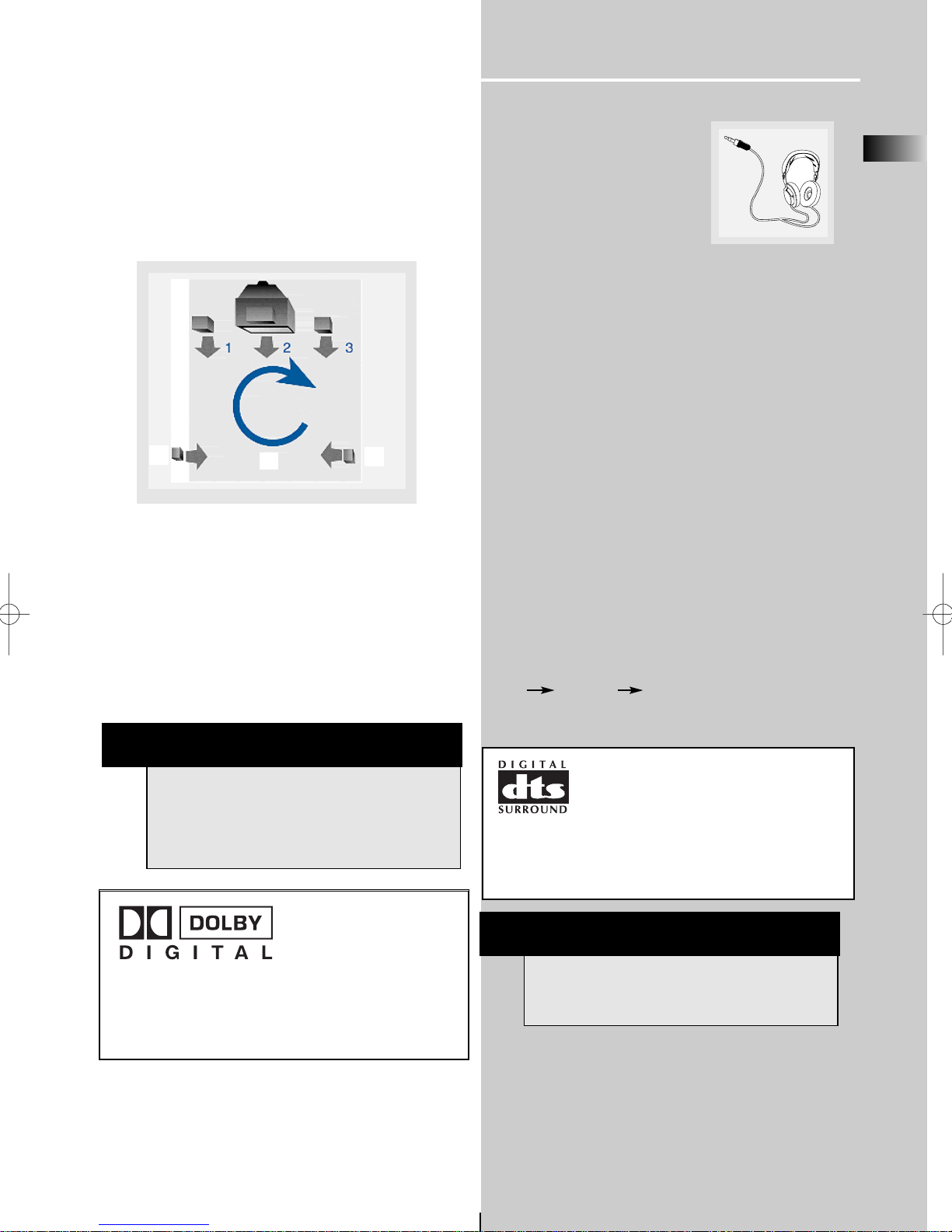
Using Headphones
To listen privately through your
audio system, use the PHONES jack
on the receiver. However, make sure
you turn down the volume before
you put on the headphones.
Increase the volume to the desired
level after headphones are in place.
Once headphones are connected, “HEADPHONE DOWNMIX
2 CHANNEL” will scroll on display. This feature automatically converts multi-channel outputs to 2 channel stereo for
your listening pleasure.
Hearing Comfort & Well-Being
• Do not play your headset at a high volume. Hearing
experts advise against continuous extended play.
• If you experience a ringing in your ears, reduce volume
or discontinue use.
Factory Setting
The unit is preset to the following setting when you first
turn on the power.
Source = TUNER
Volume setting = 25
Bass & Treble = 0 dB
Restore to Factory Settings
You can always restore all settings back to its original state.
When the receiver is in VCR mode, press the following
sequence on the main unit to restore all settings back to
factory default :
STOP REPEAT BAND / APP
NOTE
The system is equipped with Dolby Digital, and
manufactured under License from Dolby
Laboratories.
Dolby Digital
Manufactured under
license from Dolby
Laboratories. “Dolby”,
“Pro Logic” and the double-D symbol are trademarks of Dolby Laboratories.
Copyright 1992-1997 Dolby Laboratories, Inc. All Rights
Reserved.
NOTE
All preset radio stations and surround sound setting will be lost after factory setting is restored.
Courtesy Dolby Laboratories
Manufactured under license from
Digital Theater Systems, Inc. US Pat. No.
5,451,942, 5,956,674, 5,974,380,
5,978,762 and other world-wide patents
issued and pending. "DTS" and "DTS Digital Surround"
are registered trademarks of Digital Theater Systems,
Inc. Copyright 1996, 2000 Digital Theater Systems, Inc.
All Rights Reserved.
4
5
6
Page 13
Operating Your Receiver
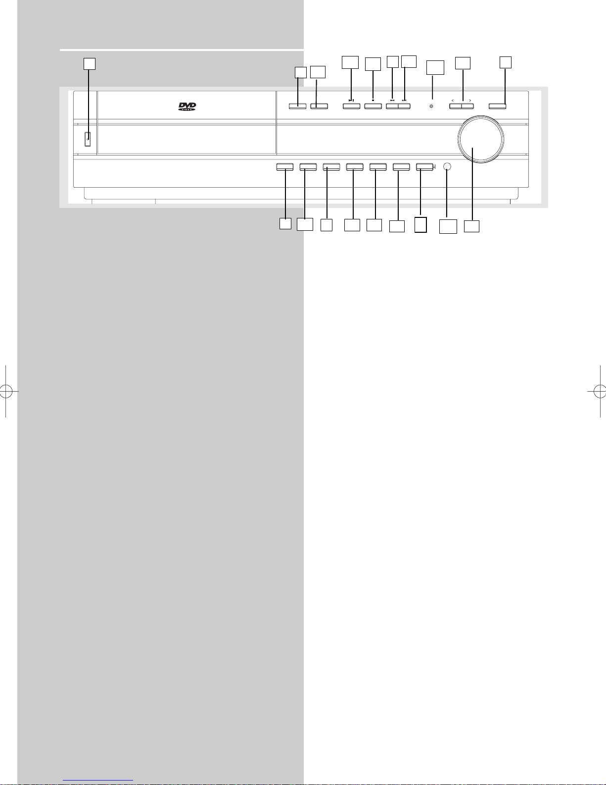
Receiver Controls
1. ON / STANDBY
• To turn the unit on/ off. When the system is turned on, the
unit will go to ECO mode (red light will be on), then press the
ON/STANBY button to power the unit up in the last mode used.
2. Source Button
• To select input source. For example, DVD/CD, VCR, etc.
3. < SOUND MODE >
• Press to select the surround sound setting or Digital Sound
Processor (DSP) mode you want. Refer to “Advanced Sound
Control” on page 16.)
4. PRESET - / SKIP REVERSE
• To move back to the beginning/previous preset memory
location in tuner mode.
• To skip to the beginning/previous track in CD mode and the
beginning/previous chapter in DVD mode (only while playing).
5. PRESET + / SKIP FORWARD
• To go to the next preset memory location in tuner mode.
• To skip to the next track in CD mode and the next chapter in
DVD mode (only while playing).
6. BAND / APP
• In Tuner mode, press to select between radio BANDS or press
and hold to enter AUTO PROGRAM mode.
7. RANDOM
• In DVD/CD mode, press to activate Random function.
8. BASS / TRE (PROG. SCAN)
• To adjust BASS / TREBLE, press this button once to choose
either bass or treble, then press preset + and preset - to adjust
level. (Bass/ treble adjustment is not allowed for DTS source)
• 1. Press and hold to activate progressive scan.
2. Press to toggle between on/off within 3 seconds.
3. Release to validate.
9. OPEN / CLOSE
• Press to open / close the CD door. (You may replace all nonplaying discs during playback.)
10. DISC SKIP
• Press to skip to the next disc in the tray.
11. VOLUME
Turn the knob to adjust volume level.
12. PLAY/PAUSE
To play and pause DVD/CD playback.
13. STOP
To stop DVD/CD playback.
14. REPEAT
• Press to toggle on the repeat function in DVD/CD playback.
• In CD mode : refer to CD / mp3 player section.
• In DVD mode: refer to DVD player section.
15. PROGRAM
• Press to toggle on the program function in DVD/CD playback.
• In CD mode : refer to CD / mp3 player section.
• In DVD mode: refer to DVD player section.
16. PHONES
Plug your headphones (not supplied) into it for your private
enjoyment. Speakers will be off when phones are inserted.
17. BLUE LED
• When progressive scan is turned on, the blue light will be on.
• When in protection mode, the blue led will blink continuously,
18. DISPLAY
• Press to toggle among track elasped time / track remain time /
disc elasped / disc remain time (Audio CD only)
19. TEST (DVD/CD mode only)
• Press STOP if the set is playing.
• Press TEST to enable test tone function for adjustment of
speaker level individually.
• Press LEFT/RIGHT key on remote to decrease / increase the
level of channel which is showing on the VFD until you can get
the correct level from the corresponding channel.
• Press PLAY to quit setting and playback or press STOP to quit
only.
1
6
2
4
14
13
12
9
11
7
5
8
10
10
3
15
16
17
18
19
ON/STANDBY
5 DVD/CD CHANGER
DIGITAL SURROUND RECEIVER RTD250
OPEN/CLOSE DISC SKIP
BAND/APP REPEAT RANDOM PROGRAM DISPLAY TEST BASS/TRE
PROGRESSIVE
SCAN
SOUND MODE
VOLUME
PROG.
SCAN
PHONES
SOURCE
Page 14

Operating Your Receiver
EN
Remote Control
Please be sure you have inserted the batteries into the remote
control (see relevant section on page 3.) You can test it by
pressing any button. If it works, the red LED will light.
1. ON-OFF
• To turn on or off the receiver and other auxiliary components (see page 14
“Using the Remote to Control Additional Components”).
2. Source Buttons
• To turn on and select various audio/ video sources.
3. CH+, CH- (Channel Buttons)
• To select programmed stations in TUNER mode.
• To skip to the next or previous chapter, track or image in DVD, CD , mp3 and
JPEG mode.
4. VOL+, VOL- (Volume Buttons)
• To adjust the volume.
5. MUTE
• To mute / unmute all audio outputs.
6. INPUT
• Press to select VCR or TV input.
7. Adjustment Buttons
• In all mode except DVD, press OK key will enter into function setting mode, for
DVD mode, press and hold the OK key is needed.
• Press OK for DIMMER mode and level adjustment.
• When the display shows the setup you want to change (dimmer, speaker level,
etc), press the left and right arrow buttons to choose, and press up and down
buttons to make changes, then press OK to finalize your choice.
8. Number Buttons
• In Tuner mode, to select a preset station.
• In DVD/CD mode, enable pull down menu by INFO*RDS key (Button 15), then
press OK key to select field to be adjusted. Press Number Buttons to direct input
the settings (e.g. CD track)
• In DVD/CD mode, when there is no OSD info are displayed, press Button 1 to 5
to select disc; when there is OSD showing, press number buttons to adjust settings (e.g. CD track)
9. MENU
• In Tuner mode:
- Press TUNER to select band
- Press to store desired frequency in memory. The flashing word PROG in red
will appear in display. Input your desired channel number while the word is still
flashing and the frequency will be stored. (For details, refer to "Storing Radio
Stations” under “Manual Preset” on page 38)
• In DVD mode, press for menu setup for DVD title.
10. Operation Buttons
• TUNER, press TUNER on the remote to enter tuner mode. In TUNER mode, you
can press TUNER to select band, and press LEFT and RIGHT buttons to tune down
or up the radio frequency.
11. RETURN
• Press to go back to previous menu or exit setup menu completely
12. AUDIO
• Press to select the audio channel you like. (e.g. LEFT / RIGHT)
• In Tuner mode, press this button to switch from ST to MONO mode and viceversa.
• In DVD mode, press to select different audio channel (if available).
13. ANGLE (DVD only)
• Press to select different screen display angles.
14. ZOOM (DVD only)
• Press to select the zoom ratio.
15. INFO-RDS
• Press to display playback information.
16.TITLE-GUIDE
• Press to go to the title menu at DVD mode.
17. DSP
• Press to change the surround sound settings. The display will toggle among any
stereo modes (for DTS (DTS stereo), for DOLBY DIGITAL signal (Dolby Digital, 3
Stereo, Stereo), DOLBY PL II MOVIE, DOLBY PL II MUSIC, DOLBY PRO LOGIC EMULATION, DOLBY 3 STEREO, ARENA, JAZZ CLUB, THEATER, STADIUM, DISCO,
STEREO)
18. PLAYMODE
• Press to toggle between different playmodes. (Random, repeat, etc.)
19. EQUALIZER
• Press to toggle between different preset equalizer mode (only available in
stereo mode.).
20. BASS
• To adjust BASS / TREBLE, press this button once to choose either bass or treble, then
press LEFT/RIGHT to adjust level. (Bass/ treble adjustment is not allowed for DTS source)
21. CLEAR / SLEEP
• Press once to enter SLEEP mode.
1
4
2
3
10
14
13
12
7
8
9
11
6
11
17
5
20
16
15
18
2
19
21
Page 15
Operating Your Receiver
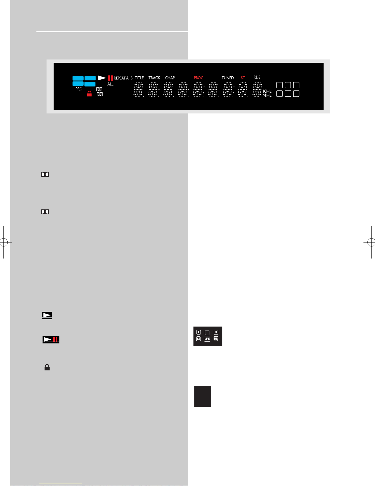
DVD / VCD / CD / mp3
• Unit in DVD, VCD, CD or mp3 mode.
DIGITAL
• Audio output is in Dolby Digital mode. (For DVD only)
PRO.LOGIC II
• Audio output is in Dolby PL II Movie, Dolby PL II Music
or Dolby Prologic Emulation mode.
DTS
• Audio output is in DTS mode. (For DVD input only)
RANDOM
• Random playback mode activated.
• Currently in playback mode.
• Currently in pause mode.
PARENTAL LOCK
• Parental lock is on and a password is required to view
DVDs above a specific rating level.
TITLE
• Title number for DVD playback.
TRACK
• Track number being played.
CHAP
• Chapter number for DVD playback.
PROG.
• Program mode is activated.
TUNED
• Tuner station detected.
ST
• Tuner stereo signal detected.
REPEAT / REPEAT TRACK / REPEAT CHAP /
REPEAT A.B. / REPEAT FOLDER (mp3 only)
• CD, mp3 and DVD in repeat mode.
KHz / MHz
• Tuner frequency unit.
• Speaker Icons.
SLEEP
• Sleep mode is activated.
• Display disc information
• Larger number refers to the current disc being played.
12
Display
DVD
DISC
3
12345
CD
MP3
VCD
DSP
PRO.LOGIC
DIGITAL
DISC
dts
EQ
SLEEP
FOLDER
LCR
LS
LFE
RS
C
DISC
3
12345
Page 16
Operating Your Receiver
EN
13
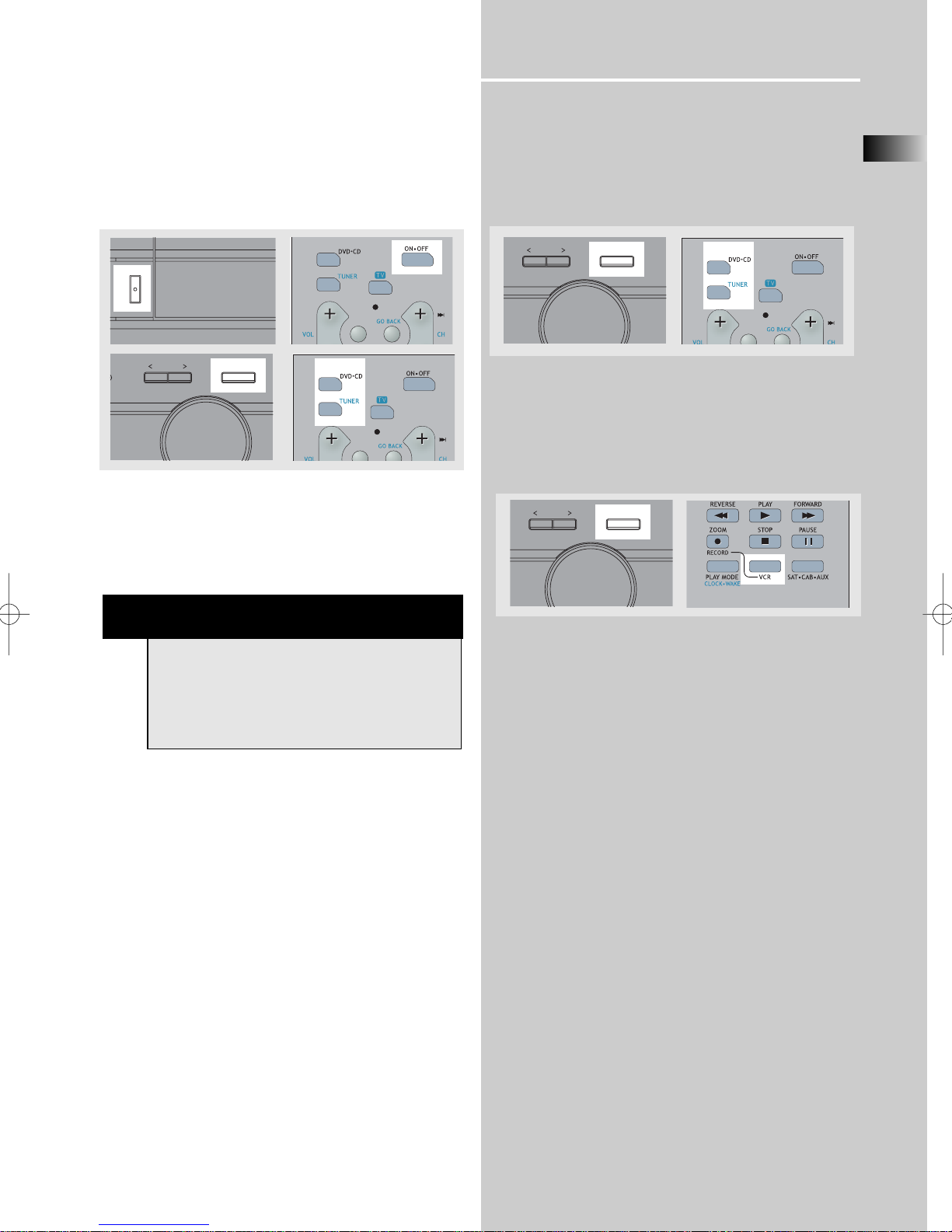
Switching on /off
• To switch on the receiver, press the ON/STANDBY button on the receiver once to enter standby mode. Press the
SOURCE button on the receiver or one of the source buttons or ON/OFF button on the remote control to power on
the receiver.
• Standby: when the receiver is on, press the ON/OFF on
the remote or the ON/STANDBY button on the receiver to
return to standby mode.
Selection of Audio/Video source
When one of the audio/video source is selected, the audio
and video input corresponding to the name will be
activated.
The receiver acts as a switching device between all the
sources that are plugged into it.
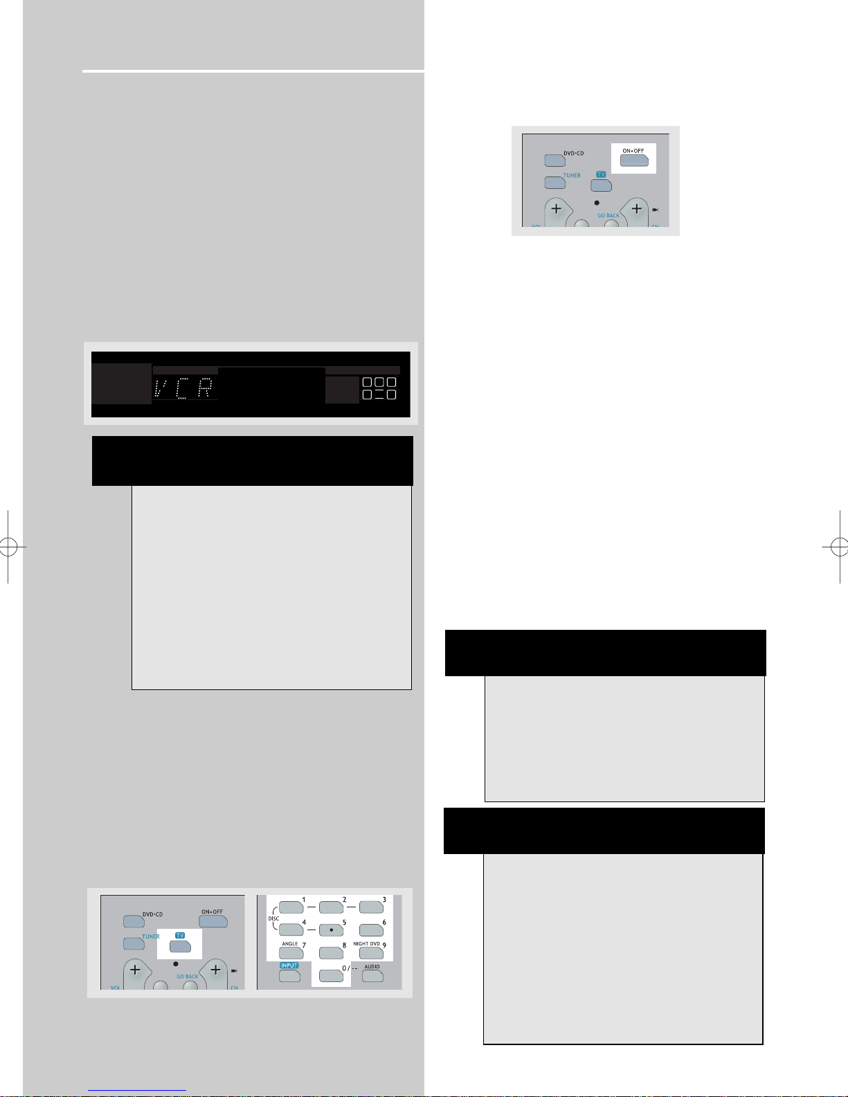
Example 1:
If you connect a VCR player to the VCR input (audio +
video) on the receiver and press the SOURCE button
until VCR shows on the display. You will be able to have
the sound and image transmitted by the VCR.
NOTE
Your receiver has a 2-week back up memory to
avoid losing settings such as preset radio stations in
case of power outage. If the receiver is unplugged
for more than 2 weeks, all the settings will be lost
and re-setting will be necessary.
5
N
ON/STANDBY
D
SSIVE
SOUND MODE
VOLUME
SOURCE
SOUND MODE
VOLUME
SOURCE
SOUND MODE
VOLUME
SOURCE
Page 17
Operating your Receiver
You can connect up to 2 audio/video sources to this
amplifier:
Source button Corresponding connector
(remote control) (receiver back panel)
- DVD/CD built-in
- TUNER built-in
- SAT SAT IN (audio / video)
- VCR VCR IN (audio / video)
When a source is selected, the source name is shown on the
display.
Example: Press the VCR button to select VCR as the source
to the amplifier.
Using the Remote to Control Additional
Components
You can set up your remote to control a TV of another
brand. You simply need to enter the code into the remote
control. (not necessary for recent RCA & Proscan models).
1. Turn on the component to be programmed.
2. Look up the brand and corresponding code number in
the code list.
3. Press and hold the TV button on the remote while entering the code from the code list using the Number Buttons.
4. Release the component button, then press the ON•OFF
button to see if the component turns off.
5. If this does not work, repeat steps 3 and 4 by trying to
use the next code (if available) listed for the brand of your
component until the component responds to the remote
command.
Volume punchthrough
By default, the VOL+/VOL- and MUTE buttons will only control
the DVD receiver, regardless which mode (TV, VCR, etc) the
receiver is in.
By programming the volume punchthrough function, you can
also control the volume of the TV.
NOTE: Controlling the TV volume can only be done in TV,
VCR and SAT.CABLE mode, not in DVD/CD and TUNER
mode.
To activate the volume punchthrough function, follow the procedures below:
1. Press and hold the VOL- button.
2. While pressing it, press the device button (TV, VCR or
SAT.CABLE) that you are programming the volume
punchthrough. The red led will turn off.
4. While you are still pressing the VOL- button, press the
device button that you want the volume command to punch
through from, the red led will turn on until the VOL- button is
released.
5. Removing the batteries will reset the remote such that once
again the receiver VOL+/-/MUTE codes are sent in TV mode.
Note: If an invalid key is pressed, the remote led blinks four
times, then you will have to start over again.
NOTE
Once your remote is encoded, you can press
ON/OFF on the remote once to turn off the component and then followed by the second time
quickly to turn off the receiver (i.e. this unit). If you
only want the receiver to be turned off, select
TUNER or DVD/CD while the unit is ON before
pressing ON/OFF.
HINT
This remote may not operate all models of the
brands shown.
If batteries are removed from the battery compartment of the remote control, all memory may be
lost. If this is the case, you will need to re-enter all
previously programmed codes again.
The remote buttons may not work exactly like the
original remote buttons for components of other
brands. Experiment with the remote and your components to see which buttons work. If only a few
functions work, you may try another code to check
if more buttons work.
14
D
V
M
NOTE
1. Your receiver has a built in tuner. Just connect
the appropriate antenna to the back of the receiver and you will be able to listen to radio stations.
(See details in Tuner section)
2. The receiver is also equipped with DVD/CD
player. Press the SOURCE button on the main unit
or DVD button on the remote to activate the feature.
3. Other sources (TV,tapes,etc) can be connected to
this unit provided that the connections are compatible.
4. Refer to the "Connecting To Audio-Visual
Components" section for details on connection.
DIGITAL
VD
PRO.LOGIC
CD
INTRORANDOM
CD
P3
LCR
LS
LFE
RS
Page 18

EN
15
Advanced Sound Control
Sound Enhancement Systems
This receiver is equipped with several built-in sound
enhancement systems.
Dolby Pro Logic II
The Pro Logic II mode uses the built-in circuit to steer the
Left, Center, Right and Surround left and right channel
audio signals and uses all five speakers to play both stereo
and Dolby Pro Logic program source, such as TV and VCR.
Dolby Pro Logic II includes Dolby Pro Logic II Movie, Dolby
Pro Logic II Music and Dolby Pro Logic Emulation.
You can use this mode to suit any stereo program source
(such as VCR / SAT) to enjoy multi-channel sound experience).
Dolby 3 Stereo
The 3 Stereo mode will redirect the Surround signals to the
front left and right speakers when only the front and
center speakers are used.
Dolby Digital
The Dolby Digital mode lets you enjoy full digital
surround from software processed in the Dolby Digital format. Dolby Digital provides better sound quality and a
more powerful presence than conventional Dolby
Surround.
This unit is equipped with Dolby Digital 5.1-channel so
that you can enjoy enhanced full digital surround sound.
Different from Dolby Pro Logic in that only four channels (
Front Left, Front Right, Centre and Rear ) are used, the new
system provides stereo separation of the rear speakers
(Rear-Right, Rear-Left ). Adding the to the 5 channels the
subwoofer channel for bass sounds (counted as 0.1 channel)
results in 5.1 channels (or 6 Channels) that bring you the
most sophisticated Dolby Digital sound enjoyment.
Digital Theater Systems (DTS))
DTS is a digital surround system which delivers six channels
of master-quality, 20-bit audio. It offers five full-range
channels plus a special low frequency effect (LFE) channel
for subwoofer, resulting in what is commonly known as 5.1
channels. It can be applied with existing 5.1 speaker configurations.
DTS is available in DVD and CD mode.
Listening
Zone
Listening
Zone
Listening
Zone
Front Left Speaker
Center Speaker
Front Right Speaker
Subwoofer
Rear Left Speaker
Rear Right Speaker
Front Left Speaker
Center Speaker
Front Right Speaker
Front Left Speaker
Rear Left Speaker
Center Speaker
Front Right Speaker
Subwoofer
Rear Right Speaker
Page 19

16
Advanced Sound Control
Stereo
The Stereo mode uses the two main channel outputs from
the front speakers.
Fine Setting of the Components
The receiver can be directly turned on by pressing the
SOURCE Buttons (like DVD/CD, SAT), which also selects the
best surround sound mode. The default surround modes for
different components are as tabled below.
If you decide to change the surround mode, you can press
the AUDIO button repeatedly to toggle among the different surround mode choices and select the one you want.
For Digital Signal (2ch PCM), or analog signal , VCR,
Tuner, SAT:
Dolby PL II Movie Dolby PL II Music Dolby PL
Emulation 3 Stereo Arena Jazz Club
Theater Stadium Disco Stereo
For Digital Signal (Dolby Digital)
Dolby Digital 3 Stereo Stereo Dolby PL II
Movie Dolby PLII Music Dolby PL Emulation
For DTS Signal
DTS Stereo
Default Settings
The receiver will keep the last selection in memory as long
as it doesn’t enter standby mode.
Input Signal Setting
The receiver defaults to the most convenient settings for
your easiest use (see table).
Analog Input
Select this setting to play analog signals from VCR or SAT.
DSP (Digital Sound Processor)
These digital sound effects resemble sounds in a real
environment such as Arena, Jazz Club, Theater, Stadium
and Disco. DSP automatically converts analog audio signals
to digital ones which enables you to adjust the sound without degrading the sound quality. Different modes will give
you different feels of size and types of listening environment. (Not available in Dolby Digital and DTS)
Night Mode
By using Dynamic Range Compression technology, you can
enjoy enhanced Dolby Digital sound quality at night without interrupting your roommates or neighbors. Night Mode
will compress the volume difference between normal voices
and sounds such as explosions, while still enjoying a Dolby
Digital DVD experience. Night Mode can be activated by
pressing the NIGHT button on the remote, DRC SOFT
(Default) will appear on the display. While DRC SOFT
(Default) is still on the display, press the LEFT or RIGHT
adjustment buttons,around the OK button, until you select
the desired mode. There are three modes (OFF, SOFT, SOFTER) for you to choose the extents of compression.
Source/
Source/ If PCM If Analog Input
Input bitstream selected
DVD/CD PRO-LOGIC II N/A
MOVIE
SAT N/A PRO-LOGIC II MOVIE
VCR N/A PRO-LOGIC II MOVIE
TUNER N/A PRO-LOGIC II MUSIC
DEFAULT INPUT (as seen on display)
Analog (SAT/ CAB)
Analog (VCR)
Built-in Tuner
Built-in
SOURCE
SAT
VCR
TUNER
DVD/CD
AVAILABLE INPUT
ANL
Built-in
ANL
Built-in
SOURCE
SAT
DVD/CD
VCR
TUNER
NOTE
SAT and VCR are just generic names. You can connect
other compatible audio/video components to these
inputs like TV, TAPE, MINI DISC, CD-RW player, etc.
Page 20

EN
17
Advanced Sound Control
Fine Setting of the Speakers
All the basic settings have already been pre-set for the
speakers included in the box.
However, to make the surround sound more effective and
suit the acoustic conditions in your listening room, you may
need to delay the signal coming from some of the speakers. Channel delay compensates for center or surround
speakers that are closer to the listening position than the
front speakers.
You may setup the speakers channel by channel: first, press
the MENU button while in stop mode to enter the setup
menu, then choose Speaker Setup.
To change the speaker size
In the speaker setup menu, press the left or right button to
select a speaker. When the speaker picture is selected, you
may press the up or down button to adjust the speaker
size. The speaker size selection allows you to setup the
device for larger size speakers, such as floor stand speakers.
To change the speaker distance
In the speaker setup menu, press the left or right button to
select a speaker. When the speaker distance column is
selected, you may press the up/down button to adjust the
distance from the front, rear and center speakers individually.
To change the speaker level
In the speaker setup menu, press the left or right button to
select a speaker. When the speaker level column is selected,
you may press the up/down button to adjust the level of
the front, rear and center speakers individually.
To test the speaker setting
In the speaker setup menu, press the left or right button to
select the "test" column, then press OK to activate. A short
noise will then come from the speakers, one speaker at a
time.
Advanced Setting
Factory Default Setting
The receiver speaker distance default settings are the
following:
Front speakers (L/R) 15 ft
Center speaker (Cch) 15 ft
Rear speaker (SUR) 10 ft
IMPORTANT NOTE
• The speakers provided with this unit are considered as small speakers. DO NOT select the large
speaker setting as this may shorten the life of the
speakers and affect the unit performance. We recommend to NOT change the speaker size setting if
you use the speakers included in the box.
• Always use the subwoofer for optimum sound
quality.
SPEAKER SETUP
EXIT
Front
Left
Center
Cch
Lch
L/S
Rear
Left
Front
Right
Rch
R/S
Rear
Right
Page 21

18
Advance Sound Control
Speaker Icons
The receiver shows you the speakers’ settings on the display
with the following icons:
Displaying Program Formats
When a digital source starts playing, the receiver automatically switches to the proper surround mode and provides
setting information via the speaker icons located on the
right-hand side of the display. (See diagram)
It is important to note, however, that not all Dolby Digital
sources are encoded with the full complement of five channels plus LFE*. Speaker icons show how many and which
speaker you have enabled (See “Fine Setting of the
Speakers”) and the letters inside the speaker icons show
which channel is present in the source information. For
example, the diagram shown means you have all five
speakers and subwoofer enabled and the digital sources
you played have five channels plus LFE complemented.
(Dolby Digital 5.1 Channels)
* LFE stands for Low Frequency Effect. The indication “LFE”
appears if the digital source contains LFE information. In
this case, the bass signal will be delivered to the subwoofer,
offering more dynamic deep bass sound effects. If the letter
is flashing, the signal is either too weak or just gone.
Front Speakers
C
Center Speaker
Rear Speakers
LFE
Subwoofer Present
C
Page 22

DVD Player
EN
19
Basic Playback Features
1. To select the DVD/CD input source, press the SOURCE
button on the main unit until "DVD/CD" appears on the
display. You may also directly press the DVD/CD source key
on the remote.
2. Press OPEN/CLOSE to open
the tray and load a disc,
with the label facing up.
Press OPEN/CLOSE again to
close the tray.
3. When READING disappears from the display, playback
starts automatically from the beginning of the disc, or the
disc menu is displayed on the screen.
• Press PLAY/PAUSE on the unit or PAUSE on the remote
to pause playing during playback. Press PLAY/PAUSE on
the main unit or PLAY on the remote to resume normal
playback.
• Press SKIP REVERSE to go back to the previous chapter
or SKIP FORWARD to move to the next chapter.
• Press STOP once to stop playback and go into resume
mode.
Quick search
1. While playing a disc, press REVERSE on the remote control to scan backwards through the disc. Press FORWARD
on the remote for scanning forward.
Press repeatedly to change searching speed to 1,2 or 3
times for VCD and 1,2,3 or 4 for DVD.
2. Press PLAY at any time to resume normal playback.
Freeze frame, frame advance
1. Press PAUSE on the remote control to freeze the picture
during playback. Each time you press it again, the next
frame is displayed.
2. Press PAUSE repeatedly to move forward in still frame
mode.
3. Press PLAY to resume normal playback.
D
G
C
E
NOTE
RESUME MODE:
The next time PLAY is pressed, the unit will begin
playback at the location where it was last stopped.
Press STOP key again to cancel the resume mode.
SOUND MODE
VOLUME
DIGITAL
DVD
PRO.LOGIC
VCD
INTRORANDOM
CD
MP3
SOURCE
OPEN/CLOSE DISC SKIP
Digital
Sound
Pr ocessor
LCR
LS
LFE
RS
DISC SKIP
ISC SKIP
PRO
S
Page 23

DVD Player
20
Slow motion playback
1. Press PLAY/PAUSE on the main unit or PAUSE on the
remote control to freeze the picture during playback.
2. Advance picture in slow motion. Press FORWARD on
the remote control for forward slow motion and REVERSE
(DVD only) for reverse slow motion
Press repeatedly to change speed to 1/16 times, 1/8 times,
1/4 times and 1/2 times.
3. Press PLAY/PAUSE on the main unit or PLAY on the
remote control to resume normal playback.
Progressive scan
1. Make sure the component output is connected to a TV
which accepts progressive scan signal. To enable progressive scan, press and hold BASS / TRE for 3 seconds in STOP
mode.
2. Once the progressive scan ON/OFF status is displayed,
press the BASS/TRE key to toggle between ON and OFF.
Wait for 3 seconds: the blue light will be on if the progressive scan function is active.
Note: The progressive Scan function can only be selected
in STOP mode.
On-screen banner display
You can access the on-screen banner display during playback to select many playback features. Each feature is illustrated with an icon. However, each feature shown in the
banner is available only if the disc was created with that
particular feature.
An invalid icon appears on the screen when you
select an icon that does not function. Also, the icon
is “grayed out” to tell you so.
General use
1. Press INFO-RDS on the remote control during playback
to show the on-screen info banner.
2. Use the LEFT or RIGHT arrows on the remote control to
move the cursor on the banner. the selected feature icon
will be highlighted.
3. Press OK to open the menu corresponding to the selected feature.
Title
Audio
Subtitles
Camera angles
Disc type
Chapter
Playmode
Time
indicator
Title icon is being
highlighted in
this example
Bookmark
ISC SKIP
BOOKMARK
ISC SKIP
LAY TEST TONE BASS/TRE
PROG.
SCAN
PHONES
Page 24

DVD Player
EN
21
Selecting a title
1. Refer to the previous page “General use” to open the
title menu.
2. Enter a title number using the number keys on the
remote control. Add 0 in front of single-digit title number
(e.g. 9 = 09). You can also use UP/ DOWN key to change the
title number.
Selecting a chapter
1. Refer to the previous page “General use” to open the
title menu.
2. Enter a chapter number using the number keys on the
remote control. Add 0 in front of single-digit chapter
number (e.g. 9 = 09). You can also use UP/ DOWN key to
change the chapter number.
Selecting audio language
1. Refer to the previous page “General use” to open the
subtitle menu, or press AUDIO on the remote control to
select the audio channel.
2. Press the UP/DOWN key to select the audio channel you
want, then press OK to confirm.
Selecting subtitle language
1. Refer to the previous page “General use” to open the
subtitle menu.
2. Press the UP or DOWN key to select the subtitle you
want, then press OK to confirm.
NoteL To exit the OSD banner, press the INFO key.
NOTE
Some discs have one title only.
NOTE
The chapter feature will not work if the disc is not
formatted with separate chapters.
NOTE
This feature only works if the disc was created with
multiple audio tracks.
NOTE
This feature only works if the disc was created with
subtitles.
Page 25

DVD Player
22
Selecting camera angle
1. Refer to page 20 “General use” to open the camera
angle menu, or press ANGLE button on the remote.
2. Press the UP or DOWN key to select the audio channel
you want, then press OK to confirm.
Selecting zoom ratio
1.Press ZOOM button on the remote to select the zoom
ratio.
2. There are two zoom ratio available, press the zoom key
to access the following zoom sequence.
NORMAL > ZOOM 1 > ZOOM 2 > NORMAL
Using bookmarks
The bookmark feature allows you to mark a point on the
disc for quick access. You can store up to 9
bookmarks.
Adding bookmarks
1. Refer to Page 20 “General use” to open the bookmark
menu.
2. Use the arrows on the remote to move the cursor (yellow
frame) to the “Mark” check line, hen press OK to add a
bookmark when reaching a scene of interest.
3. TTo add another bookmark, move the cursor to the right
with the arrow button. Then, press OK to add a bookmark
when reaching a scene of interest.
4. Move the cursor to the door icon and then press
OK to exit menu.
Recalling bookmarks
1. Refer to page 20 “General use” to open the bookmark
menu.
2. Use the arrows on the remote to move the cursor (yellow
frame) to the “Go To” check line and to the bookmarked
scene you want to recall.
3. Press OK to recall the bookmarked scene.
4. Use the arrow buttons to move the cursor to the
door icon, and then press OK to exit the menu.
Clearing bookmarks
The bookmarks are cleared each time a disc is removed
from the player or when the power is turned off
completely.
If all 9 bookmarks are in use, you can still mark new scenes
but the previous bookmarks will be erased starting from
the earliest one.
NOTE
This feature only works if the disc was created with
multiple angles.
Page 26

DVD Player
EN
23
Play mode
1. Refer to page 20 “General use” to open the playmode
menu.
2. Press the up/down buttons to select among :
Normal >Program edit/ Program play > Repeat AB >
Repeat Title > Repeat Chapter > Normal
3. Press OK to confirm the setting.
Program playback
Edit program
1. Refer to the previous page ("General use") to open the
play mode menu, or press and hold the PROGRAM button
on the front of the unit to access the program mode.
Note: Program edit can only be activated during STOP /
Resume mode. However, if there is program saved already,
program play can be activated during plaback mode.
2. The box under “Title” will be highlighted automatically.
Use the arrows on the remote to select title and chapter.
3. “Add” will be highlighted automatically after chapter is
selected. Press OK to add selected track and chapter(s) onto
playlist.
4. Move to highlight “Play” (start program playback) or
“Done” (return normal playback with program saved), then
press OK to start program playback or return to stop mode.
NOTE
Random playback is not available in DVD mode.
NOTE
You can select at maximum 32 items by repeating
steps 2 - 3.
Page 27

DVD Player
24
Delete program
1. Select the program menu from the OSD banner, or press
and hold the PROGRAM button on the main unit to display the program edit playlist.
2. Use the arrows on the remote to select and highlight the
programmed item you want to delete from the playlist
3. Highlight “Delete” and then press OK to delete the item.
4. Repeat steps 2 and 3 to delete additional items.
5. Use the arrows to select and highlight “Play” (start program playback) or “Done” (return to normal playback with
program saved) and then press OK.
Insert chapter
1. Select the program menu from the OSD banner, or press
and hold the PROGRAM. button on the main unit to display the program edit playlist.
2. use the UP or DOWN arrow to highlight and select on
the playlist the item before which you want to insert a
chapter.
3. Use the LEFT and RIGHT arrows to select Title or
Chapter, then the UP and DOWN arrows to select the
number.
4. Use the LEFT and DOWN arrows to highlight “Insert”
and then press OK.
5. Use the arrow buttons to highlight “Play” (start program
playback) or “Done” (return to normal playback with program saved) and then press OK.
Cancel program
Program will be cancelled when;
1. the disc tray is opened;
2. power is turned off;
3. STOP is pressed twice. The red PGM indicator will disappear from the display and the player will resume its normal
playback mode.
Page 28

DVD Player
EN
25
Set up menu
General use
1. Press MENU in STOP AND RESUME mode to display the
set up menu on screen. The menu shows the current set-
tings.
2. Use the arrow buttons to highlight an option and press
OK to open the selected menu.
3. Press the LEFT arrow to go back to the previous menu
or press GO BACK to exit the setup menu completely.
Audio language
This step will define the default audio language. Choosing
an audio language from the on-screen banner display will
only overwrite this setting temporarily.
1. Open the audio language menu.
2. Use the UP and DOWN arrows to select a language and
then press OK.
For languages other than the available options:
3. Press DOWN to select “Other” and then press OK.
4. Use 0-9 to enter the code for the chosen language, then
select OK to return to the main menu..
NOTE
Pressing MENU during disc playback will display the
disc menu, not the player setup menu.
NOTE
If the selected language is not available on a disc,
that disc's own default language will be used
instead.
Page 29

DVD Player
26
Subtitle language
This step will define the default subtitle language.
Choosing a subtitle language from the on-screen banner
display will only overwrite this setting temporarily.
1. Open the subtitle language menu.
2. Press the UP or DOWN arrow to select a language and
then press OK.
For languages other than the available options
3. Move down and select “Other” and then press OK.
4. Use 0-9 to enter the code for the chosen language, then
select OK to return to the main menu.
Menu language
This step will define the language of menus and other
short messages shown on screen.
1. Open the menu language menu.
2. Use the UP or DOWN arrows to scroll the selections and
select the language and then press OK to return to the
main menu.
NOTE
If the selected language is not available on a disc,
that disc's own default language will be used
instead.
Page 30

DVD Player
EN
27
Rating (Parental control)
This setting prevents the playback of DVDs that may not be
suitable for all audiences, by using the rating level that may
be encoded on the disc. If the rating level of the disc is
higher than the preset level (to be set in this step), the playback will be prohibited unless the password (see next step)
is entered.
1. Open the rating menu.
2. Use the UP or DOWN arrows to highlight the rating
requiring a password to start disc playback. Press OK to
return to the main menu. Ratings highlighted in blue
require a password.
The rating feature works in accordance with the rating
encoded in the DVD disc software. Keep in mind that all
movies and discs may not be rated. In addition to the five
standard (MPAA) rating symbols of “G” (level 2), “PG”
(Parental Guidance, level 4), “PG13” (Parental Guidance and
13 years old, level 4), “R” (Restricted, level 6) and ”NC17”
(from 17 years old, level 7), the player includes a total of 8
rating steps, corresponding to the existing disc rating steps.
These additional steps allow for a better control the of program playback for all audiences.
Level 8: All DVDs can be played (Factory preset).
Level 7 to 2: DVDs for general audiences/ children can be
played.
Level 1: DVDs for children can be played, DVDs for adults/
general audiences are prohibited.
Password
Set password
To disable the viewing of rated DVDs, a four-digit password
must be selected.
1. Open the “Set Password” menu.
2. Select “Set Password” and press OK.
3. Use the number buttons to enter the password and then
press OK.
4. Repeat step 3 to confirm the password.
Note: will be displayed on the VFD once the password is
set.
8
7
5
6R
4 PG-13
3 PG
2
1 G
Set Password
Change Password
Page 31

DVD Player
28
Change the password
In order to change the password, the current password
must first be entered
1. Open the password menu.
2. Use the number buttons to enter the password and then
press OK.
3. Use the UP and DOWN arrows to select “Change
Password” and then press OK.
4. Use the number buttons to enter a new password and
then press OK.
5. Repeat the above step to confirm the password and
return to the password menu. Use the LEFT arrow to
return to the main menu.
Clear password
1. Refer to page 25 “General use” to open the password
menu.
2. Use the number buttons to enter the password and then
press OK.
3. Move up or down the menu using the UP or DOWN
arrows and select “Clear Password”. Press OK to clear the
password. Use the LEFT arrow to return to the main menu.
NOTE
• when an incorrect password is entered, a new
password menu appears so that you can enter and
confirm the password again
• A lock icon shows on unit display when password
is required to view rated discs.
Important: keep the password in a safe place or
remember it reliably as access to rated discs or
rating/ password menus requires the correct
password.
Set Password
Change Password
Page 32

DVD Player
EN
29
TV aspect
This step selects the TV aspect, wide-screen (16:9) or
conventional (4:3).
1. Open the TV aspect menu.
2. Use the UP or DOWN arrows to select TV aspect and
then press OK to return to the main menu.
If you have a wide-screen (16:9) TV, choose “16:9
Widescreen”.
- For 16:9 movie you will get
(Do not select 16:9 widescreen setting
if you are using a 4:3 TV set. or the
image may look distorted with some
DVD disc.)
- For a 4:3 movie you will get
If you have a conventional (4:3) TV,
- if you select 4:3 letterbox for a 16:9
movie, you will get
- if you select 4:3 Pan Scan for a 16:9
movie, you will get (the left and right
edges are hidden)
- for a 4:3 movie, for both selections,
you will get
Note: You may need to deactivate progressive scan when viewing a video
program recorded in 4:3 aspect. Some 16:9 TV set will not be able to
adjust to 4:3 when progressive scan is ON. If this happens, try to disable
progressive scan.
Dynamic range
1. To disable/enable the dynamic function, enter the
dynamic range menu.
2. Use the UP or DOWN arrows to select Dynamic Range
and then press OK to return to the main menu.
Digital audio out
1. To select digital audio out, enter the digital audio out
menu.
2. Use the UP or DOWN arrows to select digital audio out
and then press OK to return to the main menu.
Soft
Softer
Off
Compressed
PCM
Page 33

CD / mp3 Player
30
The CD/mp3 playback function works in the same way as
the features available for DVD .
Press SOURCE on the main unit or the DVD/CD source key
on the remote to select the DVD/CD input source.
Loading and playing an audio CD
1. Press OPEN/CLOSE on the front panel to open the disc
tray. Place the disc on the disc tray with the label side
facing up. Press OPEN/CLOSE again to close disc tray.
2. Press DISCSKIP or 1-5 on the remote control to select
anotherdisc.The disc will be read to detect whether an
audio CD or mp3 CD has been inserted.
2. Playback begins automatically after the disc has been
read.
An audio CD or mp3 icon will appear on the
display.
3. Press PLAY/PAUSE on the main unit or PAUSE on the
remote control to pause playback. Press PLAY/PAUSE again
on the main unit or PLAY on the remote to resume normal
playback.
E
mp3 recommendations
• Use .mp3 as the extension when converting
audio files into mp3 for saving onto CD-R(W) or
CD-ROM, e.g. Rocky08.mp3. Do not use any other
extension e.g. .doc, .pdf.
• Do not use the .mp3 extension for other text or
non-audio data files as this may result in serious
malfunction and harmful noise interference.
• Most commonly available CD creation softwarecan make files compatible for the system but do
not forget to finalize your disc after creation. This
set cannot read DirectCD recordings.
•In order to get audio CD quality, you need to
record your MP3 CD at 128 kbps. You can record
up to 256 kbps. Beyond 256 kbps, the unit might
not read the CD.
• Do not combine CD Audio and MP3 tracks onto
a CD-R(W) or CD-ROM. The player will only
playback CD audio tracks from mixed CD formats.
NOTE
• If over 400 items (songs/folders) are on the disc,
only the first 400 songs can be played.
• Resume function does not operate in MP3 mode.
NOTE
If the CD is a MP3 audio CD, reading may take up
to 2 minutes.
NOTE
Be sure to remove all the discs from the disc compartment before moving or transporting the unit!
OPEN/CLOSE DISC SKIP
CD
MP3
DVD
VCD
MP3
CD
SOUND MODE
VOLUME
DIGITAL
PRO.LOGIC
INTRORANDOM
SOURCE
LCR
LS
LFE
RS
DISC SKIP
DIGITAL
DVD
PRO.LOGIC
VCD
INTRORANDOM
CD
MP3
LCR
LS
LFE
RS
Page 34

CD / mp3 Player
EN
31
4. Press SKIP REVERSE on the main unit or CH- on the
remote to return to the previous track. Press SKIP FOR-
WARD on the main unit or CH + on the remote to go to
the next track.
5. Press STOP on the main unit or STOP on the remote control to end playback.
Quick scan
1. Press FORWARD or REVERSE on the remote to scan
through a track quickly during playback. To change speed
to 1, 2 or 3 times, press repeatedly during scan. Quick scan
does not work with mp3 music.
2. Press PLAY on the main unit or the remote to resume
normal playback.
R
A
NOTE
When playback is interrupted, the location at
which it stopped will be memorized.
Playback will resume at the position it was last
stopped. Resume playback does not work with
mp3 music.
PROG
SC
ISC SKIP
Page 35

CD / mp3 Player
32
On- screen banner display for CD playback
General use
1. Press INFO on the remote control to hide and show
the on- screen banner. (Only audio CD banner)
2. Use the LEFT / RIGHT arrow keys to move the cursor on
the banner. The selected feature icon will be highlighted.
3. Press OK to open menu under the selected feature.
Selecting a track
1. Refer to “General use” to open the track
menu.
2. Enter a track number. Start any single-digit track number by a 0 (e.g. 9 = 09).
Playmode selection for CD
There are several options for this feature.
1. Normal – normal CD playback
2. Program – plays the programmed tracks (usable in stop
mode only)
3. Repeat Disc – repeatedly plays the selected or currently
playing disc.
4. Repeat Track – plays one track over repeatedly.
5. Repeat All Disc– plays all discs in the tray repeatedly.
(only workable when at least one of the discs is audio CD.)
6. Random – randomly plays all the tracks of that disc.
7. Random All Disc – randomly plays all discs in the tray
repeatedly. (works only if at least one of the discs is an
audio CD.)
8. Repeat A-B – repeatedly plays the selected time frame.
Program
Program edit - can be activated in STOP mode only.
Program play - can be activated during playback mode if
there is a saved program in the program list.
NOTE
You must be in playback mode for track selection.
Track
Bookmark
Playmodes
Disc type
Time indicator
Time display mode
Page 36

CD / mp3 Player
EN
33
Bookmarks (Audio CDs Only)
The bookmark feature allows you to mark a point on the
disc for quick access. 9 bookmarks can be selected.
Adding Bookmarks (Audio CDs Only)
1. Refer to “General use” on page 32 to open the
bookmark menu.
2. Use the arrow keys to move the cursor (green frame) to
the “Mark” check line, then press OK to add bookmark
when you reaching a point of interest.
3. To add another bookmark, move the cursor to the right
and then press OK when reaching another point of interest.
4. Move cursor to the door icon and then press OK
to exit menu.
Recalling bookmarks
1. Refer to “General use” on page 32 to open the
bookmark menu.
2. Use the UP arrow to move the cursor (green frame) to
the “Go To” check line. Then, use the LEFT or RIGHT arrow
to navigate to the bookmark you want to access.
3. Press OK to recall the bookmarked point.
4. Use the arrow buttons to move the cursor to the
door icon, then press OK to exit menu.
Clearing bookmarks
The bookmarks are cleared each time a disc is removed
from the player or when the power is turned off
completely.
If all 9 bookmarks are in use, you can still mark new points
but the previous bookmarks will be erased.
Time display (Audio CDs Only)
1. Refer to “General use” on page 32 to open the time
display menu.
2. Press OK on the remote or DISPLAY on the main unit
repeatedly to switch among "Track Elapsed", "Track
Remain" , “Disc Elapsed” and “Disc Remain” time during
playback. The selected mode is displayed on the banner.
Page 37

CD / mp3 Player
34
Program playback
Edit program
1. In STOP mode, press PROGRAM on the main unit or
enter the OSD banner to display the edit playlist (program
screen)
2. The box under “TRACK” will be highlighted. Press the
UP or DOWN arrow or number buttons to select a track.
Press OK.
3. “Add” will be highlighted automatically after track is
selected. Press OK to add the selected track to the playlist
4. Repeat steps 2 and 3 to add additional tracks to the program.
5. Move to highlight “Play” (start program playback) or
“Done” (return to normal playback with program saved)
and then press OK to confirm program playback or return
to the stop mode.
Delete Program
1. In stop mode, press PROGRAM on the main unit or
enter the OSD banner to display the edit playlist (program
screen)
2. Use the LEFT or RIGHT arrow to select Playlist, then use
the UP or DOWN arrow to select and highlight the
programmed track you want to delete from the playlist.
3. Use the arrow buttons to highlight “Delete” and then
press OK to delete a track.
4. Highlight “Play” (to start program playback) or “Done”
(to return to normal playback with program saved) and
then press OK.
Insert track
1. In stop mode, press and hold PROGRAM. on the main
unit or enter the OSD banner to display program edit
playlist.
2. Use the arrows to highlight on the playlist the item
before which you want to insert a track.
3. Refer to “Edit program” to select a track to be inserted.
4. Highlight “Insert” and then press OK
5. Highlight “Play” (start program playback) or “Done”
(return to normal playback with program saved) and then
press OK.
Cancel program
Program will be cancelled when;
1. the disc tray is opened;
2. power is turned off;
3. STOP is pressed twice. The PROG indicator will disappear
from the display, and the player will resume normal playback.
NOTE
You can select a maximum of 32 items
Page 38

CD / mp3 Player
EN
35
On- screen display for mp3 playback
Standard Play
File mode
1. In the playmode window, press the UP or DOWN arrow
on the remote to select the
standard mode.
2. Use the LEFT or RIGHT
arrow on the remote to toggle between different mp3
windows.
3. In the file window, use the
UP or DOWN arrow buttons on the remote to select the
file you wish to begin playing.
2. Press PLAY/PAUSE on the main unit or OK on the
remote control to start playback.If an mp3 is already playing, press the OK button to play another mp3 file. All the
files or folders will be played starting with the one you
have selected.
Playback stops when all the files have been played.
Folder mode
1. Use the
arrow buttons on
the
remote to
select the
folder you
wish to
play.
2. To playback all the files contained in the folder, press OK
to first enter the folder, then PLAY, if you are in stop
mode. If playback has already started, press OK.
Playback stops when all the files have been played.
3. To exit a folder, use the arrow buttons to select the <..>
then press OK.
Playmode selection for mp3
1. You can select your desired playmode in mp3 menu.
i. Standard - normal playback
ii. Playlist - play your programmed tracks
iii. Random - play tracks randomly
iv. Track repeat - repeat desired track
v. Folder repeat - repeat desired folder
vi. Disc repeat - repeat the whole disc
vii. Playlist repeat - repeat programmed tracks
viii. Playlist random - play programmed tracks randomly
2. When the Play Mode window is highlighted and blinking, use the Up or Down arrow to toggle different playmodes, then press OK to confirm.
P
Page 39

CD / mp3 Player
36
Playlist
1. In the playmode setting window, press the UP or DOWN
arrow to select playlist mode.
2. Use the UP and DOWN arrow on the remote to select on
the left the files that you wish to add to the playlist
3. Press OK to move the file to the right of the playlist.
4. Once all the files have been selected, move the cursor to
the file in the playlist and press OK to begin playlist playback.
5. Press STOP to end playlist playback.
Delete a specific File from the Program List
1. Use the LEFT or RIGHT arrow to select program list,
then use the UP or DOWN arrow to select file to be deleted and move to delete icon and press OK to delete.
Delete All
1. In stop mode, use the LEFT or RIGHT arrow to select the
“DELETE ALL” icon and press OK to clear all.
Page 40

JPEG CD
EN
37
On- screen display for JPEG CD
File mode
1. In the JPEG mode window, use the UP or DOWN arrow
to select a directory, and the OK button on the remote to
enter different directories. You can use the RETURN button
to go up one layer in the directory.
2. Use the UP or DOWN
arrow buttons on the
remote to select the file
you wish to view.
3. Press the OK button , and the picture you select will display on the screen.
4. When viewing the
image, you can press the
CH+ or CH- button to skip
to next / previous image.
Zooming / rotating the image
1. In JPEG file mode, when you are viewing an image, you
can rotate the image by pressing the LEFT or RIGHT arrow.
(not working in ZOOM mode.)
2. You can also mirror the image either horizontally or vertically by pressing the UP or DOWN arrow. (not working in
ZOOM mode.)
3. If you want to zoom in the image to full screen mode,
just press the ZOOM button.
4. In ZOOM mode, you can pan the screen at any direction
by pressing the corresponding navigation key.
5. To return to normal mode, press the ZOOM or STOP button.
Note: The zooming function will not be available if your
image pixels count is too low.
Slideshow mode
1. In JPEG mode, Press PLAY/PAUSE on the main unit or
PLAY on the remote control to start the slideshow. Pictures
will be shown on screen for 5 seconds and fade, playback
will stop until all the files are played.
2. You can pause viewing by pressing the PAUSE button, or
press the PLAY button to resume.
3. Press STOP button to go back to navigation mode.
Playmode
In JPEG mode, you can select different playmodes in the
playmode selection field.
1. Random: randomly view JPEG files.
2. Repeat disc: view all images in the disc repeatedly.
3. Folder repeat: view all images in the folder repeatedly.
Mixed mode (when playing disc containing both mp3 and
JPEG)
When reading a mixed disc, the unit will play the first mp3
(if any). However, as you navigate the disc, whenever the
cursor stops at any JPEG file, the mp3 playback will stop,
and a preview of that picture will shown on screen.
• When your cursor is on any mp3 file, press OK to start
playback.
• When your cursor is on any JPEG file, press OK to start
viewing.
Attention: The unit only supports .JPG. as a valid file
extension
P
Page 41

Radio
38
Operating the Radio
The receiver has a built-in tuner that allows for AM/FM
radio function.
Manual tuning
1. Connect the FM and AM antenna accordingly (see
"Connecting the Antenna" on page 5 section for details)
2. Press ON/STANDBY on the main unit or ON/OFF button
on the remote.
3. Press SOURCE on the front of the unit until the tuner
mode is selected. You may also directly press TUNER on the
remote control.
4. o select a band, you may press TUNER again on the
remote control. You may also press the BAND/AAP button
on the main unit.
When an FM station broadcasts Stereo sound, ST is displayed.
5. Tune the a station by pressing TUNER + or TUNER - on
the remote control repeatedly until the desired station is
found.
Alternatively, you can press and hold the same buttons for
about one second to activate the automatic SEARCH function. In this mode the receiver will automatically tune frequencies until it finds a station.
6. Repeat steps 5 to tune to another radio station.
Select a sound effect if needed by pressing DSP.
N
NOTE
1. If there is interference, modify the location
of the antenna until the optimal sound is heard.
TV and other electronic devices could be the
cause of interferences so try to position the
antenna away from them.
2. Weak signal can affect the "auto Search
function". Adjust the antenna for a better
reception and for a more efficient search.
ON/STANDBY
GRESSIVE
CAN
SOUND MODE
VOLUME
SOURCE
DIGITAL
DVD
PRO.LOGIC
VCD
CD
MP3
INTRORANDOM
LCR
LS
LFE
RS
Digital
Sound
Pr ocessor
BAND/AAP REPEAT RA
Page 42

Radio
EN
39
Storing radio stations:
The receiver can store up to 40 radio stations in memory.
You can enter every single radio station yourself or the
receiver can store all available radio stations automatically
in an ascending order.
Automatic preset storing :
1. Press BAND/AAP on the main unit or TUNER repeatedly
on the remote control to select the FM band.
2- Press and hold BAND/AAP or TUNER button for 3 seconds to start the automatic preset programming. “PROG”
will be flashing during the automatic storing process.
Radio frequencies will be browsed and radio stations
stored automatically. When all available radio stations are
stored or if all 40 memory locations are full, the auto preset will stop.
Manual preset
1. Select the band by pressing TUNER repeatedly
2. Tune to a radio station (see "Manual tuning" on page 38
above for details)
3. Press MENU on the remote control. "PROG" will appear
on the display
4. While the word "PROG " is still flashing, input your
desired preset number (1-40) using the numeric keys on the
remote control to store the radio station.
Retrieving preset stations
1. Press SOURCE on the unit or TUNER on the remote
control to enter the tuner mode
2. Press PRESET + or PRESET - on the unit or CH+ or CH -
on the remote control to tune up or down preset channels.
NOTE
A weak signal can affect the "Automatic Preset
Storing function" efficiency. Adjust the antenna
for a better reception and for a more efficient
search. No APP function for AM mode.
V
N
N
Digital
Sound
Pr ocessor
BAND/AAP REPEAT RA
Digital
Sound
Pr ocessor
BAND/AAP REPEAT RA
DIGITAL
DVD
PRO.LOGIC
VCD
CD
MP3
INTRORANDOM
LCR
LS
LFE
RS
DIGITAL
DVD
PRO.LOGIC
VCD
INTRORANDOM
CD
MP3
LCR
LS
LFE
RS
DIGITAL
DVD
PRO.LOGIC
VCD
CD
MP3
INTRORANDOM
LCR
LS
LFE
RS
PROGRESSI
SCAN
Page 43

Troubleshooting Tips
40
Power
No power ?
• Correctly connect the AC Power Cord to an AC Outlet.
Power is switching off automatically ?
• If the player is not used, i.e. no key pressed for 30 minutes while in DVD/CD mode, it automatically switches to
standby (Auto Power Off). Press the ON/STANDBY button
to switch the player on again.
The keys do not activate the functions they control (unit
and / or remote control).
• Set the ON/STANDBY key to OFF (red light on) and back
to ON again. Alternatively, turn off the power, disconnect
the power plug and then re-connect it (The player may not
be operating properly due to lightning, static electricity or
some other external factors).
• If keys still do not activate the functions they control
even when the above mentioned corrective actions are
taken, contact your RCA retailer.
• During protection such as OCP, OVP, OTP,the unit may
already go into the “Latch mode”, and the unit will need
sometime to power on again. And the blue led will blink
continuously for indication, you have to restart the unit by
press the ON/STANDBY button on the main unit.
Video and audio
There is no picture ?
• Turn on the TV set.
• Check the connections.
• Make the correct input selection on the TV set.
• If progressive scan is turned on, there will be no picture
coming out of the composite video and s-video outputs
while in DVD/CD mode.
The picture is distorted or shakes during search, forward
or reverse.
• Search, forward or reverse playback generates a slight
distortion, but this is not a malfunction.
There is no sound or it can hardly be heard ?
• Make sure the speakers are connected.
• Make sure that the MUTE function is not on.
• Check the connections.
• Make the correct audio input selection and volume
adjustment on the TV set or hifi system (e.g. AV selector).
• There is no sound during a pause (still picture), still picture advance, or slow playback.
• DTS may have been chosen as a default audio setting
No "Surround" sound ?
• Check the speaker configuration in the menu.
Noise interference appears on the TV, while watching a
TV program and the DVD player is left on ?
• Turn off the DVD player.
• The TV is too close to the audio system.
Volume level differences playing different disc types
(DVDs, audio / video CDs).
• Adjust the master volume .
No audio from one channel.
• Check the speaker level setting.
• Check the speaker wire or cable connections.
Remote control
The remote control does not work ?
• Load the batteries with their polarities (+ and –) aligned
correctly.
• Batteries are low. Replace with new ones.
• Point the remote control to the front of the player.
• Operate the remote control within a 26 ft range from the
player.
• Remove any obstacles between the remote control and
the front display of the player.
The invalid icon appears on-screen ?
• If an invalid icon appears on-screen when a button is
pressed, it is probably because :
1. The DVD does not allow it.
2. The DVD does not have this option /e.g., angles.
3. The function is not available on that part of the disc.
4. You have requested a title or chapter number or search
time that is not available.
TV or video recorder cannot be operated with the remote
control.
• Not all models can be operated with the supplied universal remote control.
No picture or the picture shown is not that of the DVD
player.
• Switch off the other video device connected to the AV
jack of the player.
Playback
Playback does not start when the PLAY key is pressed ?
• Make sure that the disc (single sided) is loaded correctly
with the title label facing up.
• Make sure you are in the proper source mode.
Playback stops immediately after the PLAY key is
pressed ?
• This player can play DVDs, Video CDs and Audio and MP3
CDs only, check that your disc corresponds to one of these
formats.
• If the disc is dirty, wipe it with a soft and clean cloth.
• Condensation occurred inside the player. Leave it at room
temperature for 1 to 2 hours.
Disc cannot be played.
• Wipe the disc clean.
• Use a RCA lens cleaner.
• The disc's region No. differs from your player's region No.
Search forward & reverse playback does not work ?
• Some DVDs have segments where search forward &
reverse playback functions do not work.
Page 44

EN
41
Troubleshooting Tips
Subtitle, language, camera angle etc.
Disc menu operation and contents may differ from disc to
disc. Please refer to the instructions accompanying the disc.
There are no subtitles ?
• check that subtitles are supposed to exist on that disc.
• Subtitles disappear from the TV screen. See page 21 to
display subtitles.
Subtitle (or language) setting cannot be changed ?
• The disc being played has been recorded in only one
language.
• Depending on the type of DVD, some segments limit
language selection.
The picture is not displayed in the correct format on the
TV (4 x 3 or 16 x 9)
• According to your TV, make the correct "TV Screen"
setting in the set-up menu (page 29).
The camera angle cannot be changed with the angle
button ?
• This function does not work when a DVD has not been
recorded with a multi-camera angle system. Some DVDs use
a multi-camera angle system only in certain portions of the
DVD.
The menu language is not the one you want ?
• The menu language for your player has not been set during set-up.
• Your preferred menu language on a DVD disc (if
available) has not been set during set up.
Audio (spoken) and / or subtitle language is not the one
selected during the initial player set-up ?
• If the audio or subtitle language is not available on the
DVD disc, the language selected during initial player set-up
will not be heard or seen. The disc's priority language
(default language) is selected automatically. If you want
another language, press menu during playback, if the disc
has its own language selection menu (Refer to page 21).
Radio
STEREO indicator is off.
• Adjust the antenna.
The signal is Mono. Severe hum or noise.
• The signal is too weak. Connect an external antenna.
Equipment Specifications:
AMPLIFIER SECTION:
Stereo mode: each 60W at 6 ohm. 10% THD @1 kHz
Subwoofer channel: 120w at 12Ω
Muting Attenuation: >65dB
Frequency Response: 20Hz to 20kHz +/-1dB
Signal to Noise Ratio: 65dB (Bypass mode)
VIDEO SECTION:
Input ( Sensitivity/ Impedance ):1Vp-p/ 75ohm
Output (Level/ Impedance): 1Vp-p/ 75 ohm
Frequency Response: 10Hz to 6MHz at +/- 3dB
Signal to noise ratio: 40dB
Crosstalk @3.58MHz: 40dB
AM TUNER SECTION:
Frequency Response: 80Hz – 2kHz +/-6dB
Usable Sensitivity: 5000uV/m @ S/N 20dB
Signal to Noise: 30dB
Image Ratio: 20dB @ 1000kHz
IF Rejection: 35dB
FM TUNER SECTION:
Frequency Response: 40Hz – 15kHz +/-3dB
Quieting: 24dBu
Signal to Noise: 60dB(stereo) / 65dB(mono)
Image Ratio: 40dB
IF Rejection: 50dB
JPEG CD SECTION:
Supported format - JPEG
Dimensions (H x W x D inch) :
Unit - 4.4 x 17 x 15.7
Front speaker - 7.8 x 4.6 x 5.5
Rear speaker - - 6.5 x 3.5 x 4.2
Center speaker - - 4.5 x 9.5 x 4.7
Subwoofer - 14 x 7.7 x 13.8
Page 45

42
Care and Maintenance
Disconnect the audio system from the power source before
performing any maintenance.
Cleaning
Clean the exterior of the system using a soft dust cloth.
The player
CAUTION! This system operates with a laser. It must only
be opened by a qualified technician.
• Never move the player during playback.
• Never put more than one disc on a tray or put a disc
slipping out of the guide area.
Handling discs
• Do not touch the signal surfaces.
• Hold discs by the edges, or by
one edge and the hole.
• Do not affix labels or adhesive tapes to the label surfaces.
• Do not scratch or damage the label. Discs rotate at high
speeds inside the player.
• Do not use damaged (cracked or warped) discs.
Cleaning discs
• Dirty discs can cause poor
sound and visual quality. Always
keep discs clean by wiping them
gently with a soft cloth from
the inner edge toward the outer perimeter. Never wipe the
disc in a circular motion since circular scratches are likely to
occur and could cause noise during playback.
• If a disc becomes dirty, wet a soft cloth in water, wring it
out well, wipe the dirt away gently, and then remove any
water drops with a dry cloth.
• Do not use record cleaning sprays or antistatic agents on
discs. Also, never clean discs with benzene, thinner, or other
volatile solvents which may cause damage to disc surface
Disc lens care
• When your disc lens gets dirty it can also cause the system
to output poor sound and visual quality. To clean the lens
you will need to purchase a disc lens cleaner which can
maintain the output sound and visual quality of your
system. For instructions on cleaning the disc lens, refer to
the ones accompanying the lens cleaner.
Important battery information
• Remove the batteries to avoid leakage if you do not use
your remote control for more than one month.
• Discard leaky batteries immediately as leaking batteries
may cause skin burns or other personal injuries.
• Dispose of batteries in the proper manner, according to
provincial and local regulations.
• Any battery may leak electrolyte if mixed with a different
battery type, if inserted incorrectly, if all batteries are not
replaced at the same time, if disposed of in fire, or if an
attempt is made to charge a battery not intended to be
recharged.
Transportation information
• Unplug the unit when the STANDBY LED is on while in
STANDBY mode.
Safety precautions
• Never open the cabinet under any circumstances. Any
repairs or internal adjustments should be made only by a
trained technician.
• Never operate this product with the cabinet removed.
• Do not touch the player with wet hands. If any liquid
enters the player cabinet, take the player to a trained technician for inspection.
• This player uses a laser to read the data on the disc. The
laser mechanism corresponds to the cartridge and stylus of
a record player. Although this product incorporates a laser
pick-up lens, it is completely safe when operated according
to directions.
• Discs rotate at high speed inside the player. Do not use
damaged, warped, or cracked discs.
• Do not touch the pick-up lens which is located inside the
disc compartment. Also, to keep dust from collecting on
the pick-up lens do not leave the compartment door open
for an extended period of time. If the lens becomes dirty,
clean it with a soft brush, or use an air blower brush
designed for camera lenses.
•
The apparatus shall not be exposed to dripping or splashing and
that no objects filled with liquids, such as vases, shall be placed on
the apparatus.
Headset safety
• Do not play your headset while the sound is at high volume levels. Hearing experts warn against extended highvolume play.
• If you experience a ringing in your ears, reduce volume or
discontinue use.
• You should use extreme caution or temporarily discontinue use in potentially hazardous situations.
• Even if your headset is an open-air type designed to let
you hear outside sounds, don’t turn up the volume so high
that you are unable to hear what is around you.
Don’t infringe
This product should only be used for the purposes for
which it is sold, that is, entertainment, violating no copyright law. Any attempts to use this product for which it is
not intended is unlawful and therefore not condoned by
Thomson.
The descriptions and characteristics given in this document are given as a
general indication and not as a guarantee. In order to provide the highest
quality product possible, we reserve the right to make any improvement or
modification without prior notice. The English version serves as the final
reference on all products and operational details should any discrepancies
arise in other languages.
V
i
d
e
o
D
i
s
c
T
h
o
m
s
o
n
D
i
g
i
t
a
l
Page 46

EN
43
Remote Codes
IMA 1038
Infinity 1062
JCPenney 1000, 1004, 1005, 1006, 1008, 1022,
1052, 1054, 1058, 1063, 1064, 1072,
1087, 1105, 1128, 1171, 1172, 1181,
1201
Janeil 1174
JBL 1062
JCB 1002
Jensen 1004, 1006
JVC 1012, 1013, 1014, 1054, 1060, 1065,
1066, 1067, 1157,1158, 1159, 1182
Kawasho 1002, 1004, 1006
Kenwood 1004, 1006, 1019
Kloss Novabeam 1068, 1069, 1174, 1183
KTV 1038, 1070, 1171, 1177
Loewe 1062
Logik 1083
Luxman 1004, 1006
LXI 1000, 1006, 1049, 1062, 1071, 1072,
1073, 1162, 1181, 1207
Magnavox 1004, 1006, 1008, 1019, 1062, 1068,
1069, 1075, 1076, 1077, 1088, 1130,
1131, 1132, 1133, 1134, 1183, 1219,
1235
Majestic 1083
Marants 1062
Marantz 1004, 1006, 1062, 1078
Megatron 1006, 1059
Memorex 1001, 1006, 1082, 1083, 1162
MGA 1004, 1005, 1006, 1019, 1022, 1051,
1079, 1080, 1082
Midland 1054, 1151, 1171, 1172, 1181
Minutz 1052
Mitisubishi 1004, 1005, 1006, 1019, 1022, 1051,
1079, 1080, 1081, 1082, 1125
Montgomery Ward 1083
Motorola 1003, 1173
MTC 1004, 1005, 1006, 1105
Multitech 1038
Multivision 1084
NAD 1006, 1071, 1072, 1185
NEC 1003, 1004, 1005, 1006, 1200
Nikko 1006, 1016
NTC 1016
Onwa 1038
Optimus 1185
Optonica 1095, 1173
Orion 1035, 1191
Panasonic 1003, 1054, 1062, 1170, 1214
Philco 1003, 1004, 1005, 1006, 1008, 1012,
1019, 1062, 1068, 1069, 1075, 1077,
1183
Philips 1003, 1004, 1008, 1012, 1019, 1062,
1068, 1069, 1075, 1076, 1086, 1087,
1088, 1089
Pilot 1004, 1171
Pioneer 1004, 1006, 1090, 1091, 1092, 1179, 1185
Portland 1004, 1005, 1006, 1016, 1171
Price Club 1105
Prism 1054
Proscan 1000, 1181
Proton 1004, 1006, 1012, 1093
Pulsar 1004, 1151
Quasar 1003, 1054, 1070, 1094
TV CODES
Abex 1172
Admiral 1001, 1173, 1211
Adventura 1174
Aiko 1016
Akai 1002
Alleron 1046
Amtron 1038
Anam National 1003, 1038, 1192, 1193, 1194
AOC 1004, 1005, 1006, 1007, 1175, 1176,
1195
Audiovox 1038
Belcor 1004
Bell & Howell 1001, 1083, 1162
Bradford 1038
Brokwood 1004
Candle 1004, 1006, 1008, 1174
Celebrity 1002
Centurion 1009
Citizen 1004, 1006, 1008, 1016,
1038, 1105, 1171, 1174,1177
Colortyme 1004, 1006, 1010
Concerto 1004, 1006
Contec/Cony 1012, 1013, 1014, 1038
Craig 1038
Crown 1038, 1171
Curtis Mathes 1000, 1004, 1006, 1015, 1105, 1162,
1171, 1212
CXC 1038
Daewoo 1004, 1005, 1006, 1016, 1017, 1018,
1127, 1171, 1196
Daytron 1004, 1006, 1171
Dimensia 1000
Dumont 1004, 1151
Electroband 1002
Electrohome 1003, 1004, 1006, 1019, 1020, 1022
Emerson 1004, 1006, 1012, 1023, 1024, 1025,
1026, 1027, 1028, 1029, 1030, 1031,
1032, 1033, 1034, 1035, 1036, 1037,
1038,1039, 1041, 1042, 1043, 1044,
1046, 1047, 1123, 1124, 1162, 1171,
1177, 1179, 1191, 1208
Envision 1004, 1006
Fisher 1048, 1049, 1051, 1162, 1180
Fujitso 1046
Funai 1038, 1046
Futuretec 1038
GE 1000, 1003, 1004, 1006, 1022, 1052,
1054, 1055, 1087, 1164, 1165, 1166,
1167, 1168, 1181, 1213
Gibralter 1004, 1151
Goldstar 1004, 1005, 1006, 1012, 1019, 1056,
1057,1058, 1155, 1156, 1171, 1172
Grundy 1038, 1046, 1171
Hallmark 1004, 1006
Harvard 1038
Hitachi 1004, 1006, 1012, 1013, 1014, 1059,
1060, 1061, 1135, 1136, 1137, 1138,
1139, 1140, 1141, 1142, 1143, 1144,
1145,1146, 1148, 1150, 1179, 1198,
1199
Page 47

44
Remote Codes
Radio Shack/Realistic 1000, 1004, 1006, 1012, 1038, 1049,
1095, 1162, 1171, 1172
RCA 1000, 1003, 1004, 1005, 1006, 1007,
1019, 1096, 1098, 1099, 1100, 1101,
1102, 1103, 1129, 1179, 1181, 1187,
1188, 1190, 1202, 1203, 1215, 1233
Runco 1151
Sampo 1004, 1006, 1171, 1172
Samsung 1004, 1005, 1006, 1012, 1015, 1019,
1104, 1105, 1106, 1171, 1172, 1204
Samsux 1171
Sansui 1191
Sanyo 1004, 1048, 1049, 1080, 1107, 1108,
1162, 1169, 1180
Scotch 1006
Scott 1004, 1006, 1012, 1024, 1035, 1038, 1046
Sears 1000, 1004, 1006, 1013, 1014, 1019,
1046, 1048, 1049, 1051, 1066, 1071,
1072, 1109, 1110, 1162, 1180, 1181,
1189
Sharp 1004, 1006, 1012, 1029, 1095, 1111,
1112, 1113, 1122, 1171, 1173
Shogun 1004
Signature 1001, 1083, 1115
Simpson 1008
Sony 1002, 1205, 1216, 1218
Soundesign 1004, 1006, 1008, 1038, 1046
Squareview 1189
SSS 1004, 1038
Starlite 1038
Supre-Macy 1174
Supreme 1002
Sylvania 1004, 1006, 1008, 1019, 1062, 1068,
1069, 1075, 1076, 1077, 1088, 1116,
1161, 1183
Symphonic 1033, 1038, 1189
Tandy 1173
Tatung 1003
Technics 1054
Techwood 1004, 1006, 1054
Teknika 1004, 1005, 1006, 1008, 1012, 1013,
1014, 1016, 1038, 1046, 1076, 1082,
1083, 1105, 1170, 1171
Telecaption 1117
TMK 1004, 1006
Toshiba 1049, 1071, 1072, 1105, 1109, 1117,
1118, 1160, 1162
Totevision 1171
Universal 1052, 1087
Victor 1066, 1182
Vidtech 1004, 1005, 1006
Viking 1174
Wards 1000, 1001, 1004, 1005, 1006, 1019,
1024, 1033, 1046, 1052, 1062, 1068,
1069, 1075, 1076, 1083, 1087, 1088,
1095, 1119, 1120
Yamaha 1004, 1005, 1006, 1019
Zenith 1004, 1083, 1151, 1152, 1153, 1154,
1210, 1217
Page 48

EN
Language Codes
For audio track and subtitle selection, see p.25,26.
Abkhazian 6566
Afar 6566
Afrikaans 6570
Albanian 8381
Amehanie 6577
Arabic 6582
Armenian 7289
Assamese 6583
Aymara 6588
Azerbaijani 6590
Bashkir 6665
Basque 6985
Bengali, Bangla 6678
Bhutani 6890
Bihari 6672
Bislama 6673
Breton 6682
Bulgarian 6671
Burmese 7789
Byelorussian 6669
Cambodian 7577
Catalan 6765
Chinese 9072
Corsican 6779
Croatian 7282
Czech 6783
Danish 6865
Dutch 7876
English 6978
Esperanto 6979
Estonian 6984
Faeroese 7079
Fiji 7074
Finnish 7073
French 7082
Frisian 7089
Galiean 7176
Georgian 7565
German 6869
Greek 6976
Greenland 7576
Guarani 7178
Gujarati 7185
Hausa 7265
Hebrew 7387
Hindi 7273
Hungarian 7285
Icelandic 7383
Indonesian 7378
Interlingua 7365
Interlingue 7369
Inupiaic 7375
Irish 7165
Italian 7384
Japanese 7465
Javanese 7487
Kannada 7578
Kashmiri 7583
Kazakh 7575
Kanyarwanda 8287
Kirghiz 7589
Kirundi 8278
Korean 7579
Kurdish 7585
Laothian 7679
Latin 7665
Latvian, Leltish 7684
Lingala 7678
Lithuanian 7684
Macedonian 7775
Malagasy 7771
Malay 7783
Malayalam 7776
Maltese 7784
Maori 7773
Marathi 7782
Moldavian 7779
Mongolian 7778
Naru 7865
Nepali 7869
Norwegian 7879
Occitan 7967
Oriya 7982
Oroma (Atan) 7977
Punjabi 8065
Pashto, Pushao 8083
Persian 7065
Polish 8075
Portuguese 8084
Quechua 8185
Ahaero- Romance 8277
Romanian 8279
Russian 8285
Samoan 8377
Sangbo 8371
Sanskrit 8365
Sents Gaelic 7168
Serbian 8382
Servo-Croatian 8372
Sesotho 8384
Setswana 8478
Sindhi 8368
Singhalese 8373
Siswati 8383
Slovak 8375
Slovenian 8376
Somali 8379
Spanish 6983
Sudanese 8385
Swahili 8387
Swedish 8386
Tagalog 8476
Tajik 8471
Tamil 8465
Tatar 8484
Telugu 8469
Thai 8472
Tibetan 6679
Tigrinya 8473
Tonga 8479
Tsonga 8483
Turkish 8482
Turkmen 8475
Twi 8487
Ukrainian 8575
Urdu 8582
Uzbek 8590
Vietnamese 8673
Volapuk 8679
Welsh 6789
Wolaf 8779
Xhosa 8872
Yiddish 7473
Yoruba 8979
Zulu 9085
Page 49

Limited Warranty (U.S.)
What your warranty covers:
• Defects in materials or workmanship.
For how long after your purchase:
• One year from date of purchase for labor and parts
• The warranty period for rental units begins with the first
rental or 45 days from date of shipment to the rental firm,
whichever comes first.
What we will do:
• Pay any Authorized RCA Audio Service Center the labor
charges to repair your unit.
• Pay any Authorized RCA Audio Service Center for the
new or, at our option, refurbished replacement parts
required to repair your unit.
How you get service:
• Take your unit to any Authorized RCA Audio Service
Center. To identify your nearest Authorized RCA Audio
Service Center, ask your dealer, look in the Yellow Pages, or
call 1-800-336-1900.
• Show the Authorized Service Center Representative your
evidence of purchase date or first rental.
• Pick up your unit when repairs are completed.
• Proof of purchase in the form of a bill of sale or receipted invoice which is evidence that the product is within the
warranty period must be presented to obtain warranty
service. For rental firms, proof of first rental is also
required.
What your warranty does not cover:
• Customer instruction. (Your Owner’s Manual describes
how to install, adjust, and operate your unit. Any additional information should be obtained from your dealer.)
• Installation and related adjustments.
• Signal reception problems not caused by your unit.
• Damage from misuse or neglect.
• Cleaning of audio heads.
• Batteries.
• A unit that has been modified or incorporated into other
products or is used for institutional or other commercial
purposes.
• A unit purchased or serviced outside the U.S.A.
• Acts of nature, such as but not limited to lightning damage.
Product Registration:
• Please complete and mail the Product Registration Card
packed with your product. It will make it easier to contact
you should it ever be necessary. The return of the card is
not required for warranty coverage.
Limitation of Warranty:
• THE WARRANTY STATED ABOVE IS THE ONLY WARRANTY APPLICABLE TO THIS PRODUCT. ALL OTHER
WARRANTIES, EXPRESS OR IMPLIED (INCLUDING ALL
IMPLIED WARRANTIES OF MERCHANTABILITY OR FITNESS FOR A PARTICULAR PURPOSE) ARE HEREBY DISCLAIMED. NO VERBAL OR WRITTEN INFORMATION
GIVEN BY THOMSON INC., ITS AGENTS OR EMPLOYEES
SHALL CREATE A GUARANTY OR IN ANY WAY
INCREASE THE SCOPE OF THIS WARRANTY.
• REPAIR OR REPLACEMENT AS PROVIDED UNDER THIS
WARRANTY IS THE EXCLUSIVE REMEDY OF THE CONSUMER. THOMSON INC. SHALL NOT BE LIABLE FOR
INCIDENTAL OR CONSEQUENTIAL DAMAGES RESULTING FROM THE USE OF THIS PRODUCT OR ARISING OUT
OF ANY BREACH OF ANY EXPRESS OR IMPLIED WARRANTY ON THIS PRODUCT. THIS DISCLAIMER OF WARRANTIES AND LIMITED WARRANTY ARE GOVERNED BY
THE LAWS OF THE STATE OF INDIANA. EXCEPT TO THE
EXTENT PROHIBITED BY APPLICABLE LAW, ANY
IMPLIED WARRANTY OF MERCHANTABILITY OR FITNESS FOR A PARTICULAR PURPOSE ON THIS PRODUCT
IS LIMITED TO THE APPLICABLE WARRANTY PERIOD
SET FORTH ABOVE.
How State Law relates to warranty:
• Some states do not allow the exclusion nor limitation of
incidental or consequential damages, or limitations on how
long an implied warranty lasts, so the above limitations or
exclusions may not apply to you.
• This warranty gives you specific legal rights, and you also
may have other rights that vary from state to state.
If you purchased your unit outside the United
States:
• This warranty does not apply. Contact your dealer for
warranty information.
Service calls which do not involve defective materials
or workmanship are not covered by this warranty.
Costs of such service calls are the sole responsibility
of the purchaser.
Page 50

Limited Warrranty(Canada)
What your warranty covers:
• Defects in materials or workmanship.
For how long after your purchase:
• One year from date of purchase for labor and parts
• The warranty period for rental units begins with the first
rental or 45 days from date of shipment to the rental firm,
whichever comes first.
What we will do:
• Pay any Authorized RCA Audio Service Center the labor
charges to repair your unit.
• Pay any Authorized RCA Audio Service Center for the
new or, at our option, refurbished replacement parts
required to repair your unit.
How you get service:
• Take your unit to any Authorized RCA Audio Service
Center. To identify your nearest Authorized RCA Audio
Service Center, ask your dealer, look in the Yellow Pages, or
call 1-800-336-1900 / 1-866-723-6486.
• Show the Authorized Service Center Representative your
evidence of purchase date or first rental.
• Pick up your unit when repairs are completed.
• Proof of purchase in the form of a bill of sale or receipted invoice which is evidence that the product is within the
warranty period must be presented to obtain warranty
service. For rental firms, proof of first rental is also
required.
What your warranty does not cover:
• Customer instruction. (Your Owner’s Manual describes
how to install, adjust, and operate your unit. Any additional information should be obtained from your dealer.)
• Installation and related adjustments.
• Signal reception problems not caused by your unit.
• Damage from misuse or neglect.
• Cleaning of audio heads.
• Batteries.
• A unit that has been modified or incorporated into other
products or is used for institutional or other commercial
purposes.
• A unit purchased or serviced outside Canada.
• Acts of nature, such as but not limited to lightning damage.
Product Registration:
• Please complete and mail the Product Registration Card
packed with your product. It will make it easier to contact
you should it ever be necessary. The return of the card is
not required for warranty coverage.
Limitation of Warranty:
• THE WARRANTY STATED ABOVE IS THE ONLY WARRANTY APPLICABLE TO THIS PRODUCT. NO VERBAL OR
WRITTEN INFORMATION GIVEN BY THOMSON MULTIMEDIA LTD., ITS AGENTS OR EMPLOYEES SHALL CREATE A GUARANTY OR IN ANY WAY INCREASE THE
SCOPE OF THIS WARRANTY.
• REPAIR OR REPLACEMENT AS PROVIDED UNDER
THIS WARRANTY IS THE EXCLUSIVE REMEDY OF THE
CONSUMER. THOMSON MULTIMEDIA LTD. SHALL NOT
BE LIABLE FOR INCIDENTAL OR CONSEQUENTIAL DAMAGES RESULTING FROM THE USE OF THIS PRODUCT.
EXCEPT TO THE EXTENT PROHIBITED BY APPLICABLE
PROVINCIAL LAW, ANY IMPLIED WARRANTY OF MERCHANTABILITY OR FITNESS FOR A PARTICULAR PURPOSE ON THIS PRODUCT IS LIMITED TO THE APPLICABLE WARRANTY PERIOD SET FORTH ABOVE.
How Provincial Laws relates to warranty:
• This warranty gives you specific legal rights which are in
addition to statutory warranties that may vary from
Province to Province.
If you purchased your unit outside Canada:
• This warranty does not apply. Contact your dealer for
warranty information.
Service calls which do not involve defective materials or workmanship are not covered by this warranty. Costs of such service calls are the sole responsibility of the purchaser.
EN
Page 51

FCC Information
1
Page 52

Limited Warranty (Mexico)
Centro de Ser
vicios A
utorizados Express (ser
vicio en 24 horas)
México,
D.F.
Monterre
y. N.L.
Guadalajara,
Jal.
Digital Ser
vice
Audio Estéreo Aguilar
Servicio Especializado de Jalisco
Av.3 A No
.12, Local 2
Gral.Zuazua 738 Nte
.
Enrique Díaz de Leon No
.821
Col.Santa Rosa
Col.Centro
Col.Sag
rada Familia
México, D
.F.
Monterre
y.N.L.
Guadalajar
a, Jal.
Tel 01 53889621
Tel 01 (8) 3724989
Tel 01 (3) 1267431
55877599
3755440
1267430
55878971
3755884
8253229
55673972
82582
A
GU
ASCALIENTES
CAMPECHE
Electrónica JIMSA
Videoservicio
Electronica T ony
Vacom
Av.Adolfo López Mateos No
.230 ote.
Av.López Matees No
.24
Priv.De la calle 6ta or
iente No.7
Av.Morelos 1016 ote
.
Col.
Centro
Col.Barrio Sn.
Roman, C
.P.24040
Col.Centro
Col.Centro
Aguascalientes
, Ags.C.P.
Campeche
, Camp
.
Cd.
Delicias, Chihuahua
Torreón, Coah.
C.P.27000
Tel.
(01-49) 15 51 81 / 78 07 57
Tel.(01-981) 6-3333
Tel.
(01-14) 74 30 26
Tel.
(01-17) 18 39 05, 22 15 51
Fax.(01-49) 15 81 00
Fax.(01-981) 1-0664
Fax.(01-14) 74 30 26
Fax.
(01-17) 18 11 98
BAJA CALIFORNIA NOR
TE
CHIAP
AS
Electro Vision
Electrónica General Internac
KC Vídeo
Taller Electrónico
Tony
Allende No
.114 esq.Xicotencatl
Blvd.
Insurgentes No
.16174, Loc.
2AC.
10a.Norte Or
iente No.153A
20 de No
viembre No
.1521
Zona Centro
Plaza de Abastos Los Almos
Col.Centro
Col.Centro.
Piedras Neg
ra
s, Coahuila.
C.P.
Tijuana, BCN C
.P
.22440
Tuxtla Gutiérrez, Chis
.C.P.29000
Cd.
Camargo
, Chihuahua.
C.P.
T
el.
(878) 21875
Tel.
( 01-66 ) 21 22 15
Tel.( 01-961 ) 8 19 08;
8 36 43
Tel.
(146) 234 67
F
ax.
(878) 21875
Tel./ F
ax:
( 01-66 ) 21 22 15
Fax.
( 01-961 ) 8 19 08
Fax.
(146) 234 67
Multiservicios del Norte
Baja Electr
onics
Serv. Elec. Especializado
CO
AHUILA
5 de Mayo 295sur.
Hacienda de Corr
alejo No
.2099
Cuahutemoc No
.2A
Electrónica Pr
ofesional
Col.Centro
Col.Hidalgo
Col.
Centro
, C.P.29200
Blvrd.
Francisco Coss No
.450-1
Sabinas, Coahuila.
C.P.26700
Mexicali, B
.C.N.C.P.21389
San.
Cristóbal de las Casas
, Chis
.
Col.
Centro
Tel.
(861) 264 31
Tel.(01-65) 619818, 619808
Tel/F
ax.
(01-967)8-1355
Saltillo
, Coah C
.P.25000
Fax.
(861) 264 31
Fax.(01-65) 619808, 619818
Fax.
(01-967)8-1355
Tels
.( 01-84 ) 10 03 00
Tel.
/ Fax:( 01-84 ) 12 30 44
COLIMA
Ser
v. Electrónico Ensenada
Ele Aplicada Ser
v Digitales
Elec. Saturno de Colima
Calle 4ta No
.1050, Local B
4a.
Av., Sur No.51
Audio y
Video Electr
onica
Nig
romante No
.138
Col.Centro
.
Col.
Centro
, C.P.30700
Miguel Blanco 307-A
Col.Centro
Ensenada, B
.C.N.C.P.22800
Tapachula, Chis
.
Col Zona Centro
.
Colima, Col.
C.
P.28000
Tel.(01-61) 740 0532
Tel.
(01-962)6-9998
Monclo
va, Coahuila.
C.P.25700
Tel.
( 01-331 ) 4 55 54, 4 50 00
Fax.(01-61) 788356
Fax.
(01-962)5-4578
Tel.
(01-86) 33 94 06
Tel.
/ F
ax:
( 01-331 ) 4 55 54
Fax.(01-86) 33 94 06
B
AJ
A CALIFORNIA SUR
CHIHU
AHU
A
Lab. Elect.
De la Mora
Digital Sound
Zener Electrónica
Electro Visión
Allende No
.110
16 de Septiembre No
.390
Trasviña y Retes No
.3503A
Juan Aldama No
.6 y Presid.
Carr
anza
Co
l.Centro
Col.Centro
Col.
Sn.
Felipe
Col.
Centro
Manzanillo
, Col.C.P.28200
La Paz, Baja Calif
ornia Sur
Chihuahua, Chih.
C.P.31240
Nue
va Rosita, Coahuila.
C.P.
Tel.
( 01-333 ) 2 30 04
Tel.(112) 32017
Tels
.( 01-14 ) 14 01 16;
26 50 41
Tel.
(86) 14 58 44
Tel.
/ F
ax:
( 01-333 )
Fax.(112) 32017
Tel.
/ F
ax:
( 01-14 ) 26 50 41
Fax.
(86) 14 58 44
DISTRIT
O FEDERAL
Video Ser
vicio Beluz
Magnavox
Electronica Rico
SIMEL
Carretra a todos Santos No
.32
Tlaxcala 1161
Iturbide y Man
uel Acuña
Río Churub
usco No.2215
Col.Inf
ona
vit Las Br
isas
.
Col.
Hidalgo
Col.
Centro.
Col.Agrícola Oriental
Los Cabos san Lucas
, BCS C.P.23410
Cd.Juarez, Chihuahua.
C.P.32010
Cd.
Acuña, Coahuila.
C.P.26250
México, D
.F.C.
P.08500
T
els.(01-114) 313 65
Tel.
(01-16)12 40 31
Tel.
(877) 236 23
Tel.
756 0883
Fax.(01-114) 313 65
Fax:
(01-16)12 40 31
Fax:
756 0883
Novatron.
TV Servideo
Diag.San Antonio No.
1213
Or
iente 9 No.
182
Col.
Narva
r
te
Col.
Ref
or
ma
México, D
.F.
C.P
.
03020
Cd.Neza, Edo.
De Mex.
C.P
.
57840
Tel.639 0812
Tel.
5857 2547
Fax:
639 1184
Fax.5857 6399
Electrónica Rangel.
Servicio Son
y
Visión
San F
elipe No.
157
Prensa No
.
1253
Col.
Pedregal de Santa Ursula
Col.
P
rensa Nal.Ind.V
allejo.
México D.
F.
C.P
.
04800
Tlanepantla, E.D
.M.C.P
.
54170
Tel.619 3213
Tel.587 75 99
Fax:619 4565
Fax:587 89 71
GU
ANAJU
A
T
O
DURANGO
T
ecnología Electrónica
Macroservicios.
Blvd.
Adolfo López Mateos No.2834A
Calle Patoni No.105 sur.
Col.Haciendas El Rosario
Col.
Centro
León, Gto.
C.P
.37130
Durango, Dgo.
Tel:(01 4) 773 6634
Tel.
(01-18) 12 26 86
Fax.(01 4) 773 6634
Fax.
(01-18) 12 26 86
Mar Electronic's
EST
ADO DE MEXICO
Brisas No.
999
Electrónica Alcántara.
Col.
Las Reinas, C.P.
36660
Refor
ma No
.3
6
Irapuato, Gto.
Col.Centro
Tel.(01-462)4-7140
Chalco, Edo.
de Me
x.
C
.
P
.
56600
F
ax.
(01-462)4-7
140
Tel.( 01-597 ) 51 847
F
ax:
( 01-597 ) 51 847
T
ele Ser
vicio Chucho.
Blv Adolfo López Mateos No 510 Pte
Ctr
o Serv.
Electrónicos
Col.
Centro
, C
.P
.38000
L.
Po
r
tillo
, esq.Blvd.Coacalco
Cela
y
a, Gto.
Col.Villa de las Flores
Te
l.
(01-461) 2-4714,
Coacalco, Edo.
de Me
x.
C.P
.
55710
F
ax.(01-461)
3-0591
Tels.
879 3404;874 6006
F
ax:
898 2464
T
e
le Radio Ortega.
A
v.
16 de Septiembre No.
1076
SHUREE Electrónica
Col.
Centro
, C
.
P
.
38600
A
v.
De los Maestros No.
113A
Acambaro, Gto.
Col.
Centro
, C.P
.
50060
Tel.(01-417)2-0780
Toluca, EDM.
F
ax.(01-417)2-0780
Tel.(01-72)14-9330,
F
ax.
(01-72)13-3424
Page 53

Limited Warrranty(Mexico)
GUERRER
O
M
ultiser
v Prof. Zam
ora
Q
UERET
AR
O
SONORA
Esp.
E
lectrónicas
Electrónica D
igital B
O
R
R
Nue
va Elec. Auditron
5 de Mayo No
. 699A
Blauton Industr
ial
Wong's Electrónicos
Matamoros poniente 225
A
v.
J
uárez No
. 516
Aquiles Serdan No
. 14B
Col. El Duero
A
v.
Universidad No
. 44B
Monteverde No.267 esq. Balderr
ama
Col.
Centro
Col.
27 de Septiembre
Col. Centro
Zamora, Mich. C
.P. 59690
Col.
P
athe
Col. Balderr
ama
Cd.Victor
ia, T
amps. C.P. 87000
P
oza
Rica, Ver. C.P
. 93320
Acapulco,
Gro. C.P. 039300
Tel. ( 01-351 ) 5 54 16
Querétaro, Qro
.C.P. 76020
Hermosillo, Son. C.
P. 83180
Tel. (01-131) 299 45
T
el. ( 01-782 ) 3 69 49
Tels. ( 01-74 ) 82 62 42
Tel. / Fax: ( 01-351 ) 5 54 16
T
els.
(
01-42 ) 23 22 66;
23 49 34
Tels. ( 01-62 ) 10 54 95;
10 05 86
Fax.(01-131)
251 93
Fax.( 01-782 ) 3 69 49
Tel. / Fax: ( 01-74 ) 83 20 62
T
el. / Fax: ( 01-42 ) 23 22 67
Tel. / Fax: ( 01-62 ) 10 54 95
MORELOS
M
icronics
Electrónica D
IC
A
HID
ALGO
E
lectrónica H
er
tz
Q
UINT
ANA R
OO
D
asetronik.
Calle 10 No
. 607.
F
.
del Paso y Troncoso No
.
908
Tec. Electrónica D
igital
Insurgentes No.190
Electrónica B
eta
Guerrero No.308-A este.
Col.
Jardin 20 de No
viembre
Col.
Centro
Blvd.Valle de San.
Javier No.
Col. Emiliano Zapata
A
v. Sun Yax Chen No
. 43 Loc.
4
Col. Centro.
Madero
, T amps. C.P. 89440
Veracruz,
Ver. C.P
. 91700
Col.
Fracc. Valle de San.
Javier
Cuautla, Mor.C.P. 62744
Col.
Centro
Navojoa, Sonor
a. C.P. 85800
Tels
.( 01-12 ) 15 96 89
T
els.
(
01-29 ) 31 20 33;
31 22 96
Pachuca, Hgo
.C.P. 42086
Tel. ( 01-735 ) 3 84 10
Cancun, Q. Roo
.C.P
.
77508
Tel. (01-642) 240 64,
F
ax: ( 01-12 ) 10 38 82
T
el. / Fax:( 01-29
) 31 2 33
Tel. ( 01-771 ) 3 24 36
Fax. ( 01-735 ) 3 84 10
T
el. ( 01-98 ) 84 54 12
Fax.(01-642) 136 64
Tel. / Fax: ( 01-771 ) 3 24 36
Fax.( 01-98 ) 87 38 13
Laboratorio Electrónico
Seguridad Plus.
Electrónica H
er
tz
Audio video Electrónica
Washington 3142
Oriente 4 No
. 187 Esq. Sur 5
Electrónica Especializada
Libertad No. 108
Electr
onicos y M
as
A
v.
Zaragoza No.516 pte.
Col. Juarez (Centro)
Col.
Centro, C.P
.
Independencia No
. 102 Loc.
C
Col. La Carolina
Ignacio Zaragoza No
.
204-A
Col.
Centro.
Nuevo Laredo
, T amps .C.P. 88000
Orizaba, Ver .
Col.
Centro, C.P. 43600
Cuernav
aca, Mor.C.P. 62190
Col.
Centro.C.P. 77000
Cd. Obregon, Sonor
a. C.
P
. 23000
Tel. (01-87) 14 95 92, 14 98 52
T
el
.(01-272) 5-0235
Tulancingo, Hgo
,
Tel. ( 01-73 ) 13 90 92
Chetumal, Q. Roo
T
el. (01-64) 14 38 28
Fax.(01-87) 14 71 71
Tel. (01-775)5-2654 3-9120
Fax.( 01-73 ) 13 09 49
T
el.
(983) 26663, 24622, 21562
Fax.(14 75 75)
YUCA
T
AN
Fa
x. (01-775)5-2654 3-9120
Fax.(983) 26014
Electronica Em
m
an
uel
C
inescopios
NUEV
O LEÓN
Electrónica U
niver
sal.
Obregon No.205A
Calle 70 No
. 443, oc.
7 por 49
J
ALISCO
Audio Estereo A
guilar
SAN LUIS POT
OSI
Calle 29 A
v. Alfonso Idberr
y No
. 401
Zona Centro
Col.
C
entro
Serv.Esp.
D
e Jalisco
Gral. Zuazua 738 Nte
.
Electronica Especializada
Col.
Centro
Cd. Mante, T
amaulipas. C.P. 89800
Mér
ida, Y uc.C.P
. 97000
Ignacio Ramirez No
. 567
Col. Centro
Manuel J.Clouthier No. 212C
Cd. Guaymas, Sonora.
C.P
. 85400
Tel. (01-123) 290 81
T
els. ( 01-99 ) 28 54 2
8, 28 59 05
S.H.
Sta.Teresita
Monterre
y, Nvo. León. CP. 64000
Col.
Las aguilas
T
el. (01-622) 29 411
Fax.(01-123) 290 81
T
el. / Fax: ( 01-99 ) 28 59 05
Guadalajara, J
al. C.P. 44200
Tels. ( 01-8 )372-4989 / 375-5440
San Luis P
otosí, SLP.
C.P
.
78270
Tels. ( 01-3 ) 825-3229, 827-0721
Tel. / Fax: ( 01-8 ) 375-5884
T
els. ( 01-48 ) 17 62 79
VERA
CR
UZ
ZA
CA
TECAS
Tel. / Fax: ( 01-3) 825-3229
T
el. / F
ax: ( 01-48) 14 19 02
Electr
o
nica C
astillo
G
rupo D
igital
Electronica M
ario.
Teleservicio M
urillo
Noche Buena # 37
I. Zaragoza No. 212
Morelos P
oniente No
.
1214
Electrónica Integral
Allende No
. 595 Sur.
Estereo C
ar
Col.
El r
astro
Col.
Centro
Col.
Centro
Candelaria No. 202, Esq. Analco
Col.
Centro
Neg
rete No.612
Nogales, Sonora. C.P
. 84000
Coatzacoalcos,
Ver. C.P.96400
Zacatecas
, Zac. C.P.
Col. Sta. María
Cd. Linares, Nv
o León. C.P. 67700
Col.
Centro
T
el. (16) 314 6857
T
el. ( 01-921 ) 2 02 29
T
el. (01-492) 275 61
Puerto
Vallar ta, Jal. C.P
. 48348
T
el. (01-821) 266 50
Cd.
Valles, SLP
.C.P. 79000
Fax.
(16) 312 3087
Fax.
( 01-921 ) 2 02 29
Fax.(01-492) 27
5 61
Tels. ( 01-322 ) 4 37 36
Fax. (01-821) 266 50
T
el. (01- 138) 206 51
Tel. / Fax: ( 01-322 ) 4 85 90
Fax.(01- 138) 206 51
T
AB
ASCO
Ser
v Técnicos
Prof.
NA
Y
ARIT
Elec.
Sigm
a de
Tabasco
A
v. 13 No.
400 Esq. Calle 4
Setesa
Electrónica Show
SINALO
A
A
v. Gregor
io Méndez No.
2819
Col.
Bella Vista
5 de F
ebrero No.2786
San Luis No
. 118 sur
Serv.Electrónico del Pacifico
Col.
Atasta
Córdoba, Ver. C.
P
. 94500
Col.
Rancho Blanco
Col. Centro
Mariano Escobedo No
. 1022
Villahermosa, T
ab.C.P
. 86100
T
el.
( 01-271 ) 2 73 22
Tlaquepaque
, Jalisco.C.P. 44890
Tepic, Nay. C
.P
. 63000
Col.
Centro
T
els. ( 01-93 ) 54 00 33; 54 20 30
Fax.( 01-271) 2 25 39
T
el. (01-3) 635-4404, 635-1875
Tel. ( 01-321 ) 4 58 00
Mazatlán, Sin. C.P. 82000
T
el.
/ Fax:
( 01-93 ) 54 00 33
Fax. (01-3) 635-4404, 635-1875
T
el. / Fax: (01-321) 4 58 00
Tel. ( 01-69 ) 82 01 55
Electrónica A
rizona
Tel. / Fax: ( 01-69 ) 82 01 55
T
AMA
ULIP
AS
Bustamante No.
46
MICHO
A
CAN
O
AXA
CA
Electrónica D
igital
Col.
Centro
A
lka Electrónica
E
l Francistor
R
eparaciones Electrónicas
Independencia No.
112 esq.
11
J
alapa,
Ver.
C.P
.
91000
García de León No
. 271
Húsares No
. 207
J.Jose Ríos No
. 178 ote.
Col.
Centro
T
el. ( 01-28 ) 18 78 68
Col. Chapultepec Sur
.
Col. Centro
Col.
Centro.
M
atamoros, Tamps
.C.P. 88000
Fax.( 01-28 ) 12 25 34
Morelia, Mich.
C.P. 58260
Oaxaca, Oax.
C.P. 68000
Culiacan Sinaloa.
C.
P. 81200
T
el. ( 01-88 ) 13 50 13
T
els. ( 01-43 ) 14 55 21;
15 90 36
Tel. ( 01-951 ) 6 47 37
T
el. (01-67) 16 81 32, 16 51 45
T
el. / Fax. ( 01-88 ) 13 50 13
C
om
.
y Electrónica
T
el. / Fax:
( 01-43 ) 15 94 25
Fax. ( 01-951 ) 472 97
Fax.(01-67) 16 81 32, 16 51 45
Miguel Hidalgo No
. 103
C
entro de Ser
vicio Lugo
Col. Buena Vista
Sur
C
entro Electrónico Son
y
PUEBLA
Electrónica M
orelos
.
Rosalinada Guerrero No
.
285
Minatitlan,
Ver. C.P. 96730
Justo Mendoza No
.12
Serv.Express Electrónico
Morelos No
. 201 ote
Col.
P
rol. Longoriiia
T
el. ( 01-922 ) 3 15 65
Col.
Centro
Prol.
Refor
ma No.6908A
Col. Centro.
Reynosa, T
amps
.
C.P
.
88699
T
el. / Fax: ( 01-922 ) 3 15 65
Uruapan, Mich.
C.P
. 60000
Col.
La Libertad
Los Mochis
, Sinaloa. C.P. 81200
T
el. ( 01- 89 ) 24 92 43
Tels. ( 01-452 ) 4 37 78;
4 08 38
Pueb
la, Pue.C.P. 72130
Tel. (01-68) 12 05 88
T
el. / Fax:
( 01-89 ) 24 92 43
T
el. / Fax:
( 01-452 ) 4 59 09
T
els. (01-22 ) 49 78 19; 37 02 82
Fax.(01-68) 12 05 88
T
el. / Fax:
( 01-22 ) 31 32 93
Page 54

Comercializadora Thomson de México, S.A. de C.V.
RTD250
Receptor de audio/vídeo Dolby Digital DVD
Miguel de Cervantes Saavedra 57 Col. Ampliación Granada
C.P. 11529 Mexico D.F.
Telefono: (55)25 81 53 20 RFC: CTM-980723-KS5
Autorizado mas cercano a su domicilio
AS:
via presentación de la factura o nota de compra.
Comercializadora Thomson de México
excepto los televisores con pantalla de 63,5 cm (25 pulgadas) o mas
serán reparados en el domicilio del cliente
la recepción del producto en el Centro de Ser
3.Todos los productos deberán ser lle
4. El tiempo de reparación en ningún caso será ma
5. Para la adquisición de par
NOT
En caso de extravío de la póliza, el consumidor debe recurr
Para su comodidad, solicite inf
su reposición, pre
1. Para ser ef
2. Comercializadora Thomson de Mexico se compromete a repar
compra, junto con el producto en cualquier
Autorizados, (que se indican en la hoja ane
piezas y componentes def
criterio de dicha empresa no sea posib
exactamente del mismo modelo o su similar
la red de servicios, que se deriven del cumplimiento de esta póliza de gar
serán cubiertos por Comercializador
ectiv
a esta gar
Accesorios
Equipos de Audio
Reproductor de DVD
Videocámaras
Televisión de Pro
Videocaseteras
yección
Comercializadora Thomson de México S
en todas sus partes y mano de obr
y funcionamiento, a par
siguiente término:
Televisores c/cinescopio de 36,6 cm.
(14 pulgadas) y menores
Televisores c/cinescopio de 48,3 cm
(19 pulgadas) y mayores
Producto Partes Mano de Obra
POLIZA DE GARANTIA
tes y accesorios
01-800-1117221
ormes sobre la localización del Centro de Ser
, llamando al:
, .
.
, contactar al 01-800-1117221 o acudir a
vicio Autorizado.
y
or a 30 días, contados a par
ir a su distrib
No.Poliza:
uidor para
vicio
•
Comercializadora Thomson de Mexico
Si se ha tratado de reparar el aparato por personas no autorizadas por
•
f
Si el producto ha sido alter
abr
icante u ocasionadas por el consumidor.
tir de
•
caso omiso de los cuidados y adver
Si el producto ha sido utilizado en condiciones distintas a las normales y/o se hacen
ectuosos sin cargo al consumidor
vados a cualquier Centro de Ser
a Thomson de México S.A de C.V.
le la reparación, cambiar por uno nuevo
.Los gastos de transpor
vicio Autorizado
tación dentro de
, los cuales
antía,
,
•
que acompaña al producto.
Si el producto no ha sido operado de acuerdo con el instructivo de uso en español
xa), o en el lugar donde fué adquir
, o en caso de que a
ar y/o reponer las
ido.
,
EST
A GARANTIA NO
antía se requiere presentar esta póliza y/o f
CONDICIONES
a de nuestros Centros de Ser
actura de
vicios
1 año
1 año
SELLO Y FIRMA DEL VENDEDOR
1 año
1 año
1 año
1 año
1 año
1 año
FECHA DE COMPRA: ___________________________________________
DIRECCION: ___________________________________________________
__________________________________________________________________
.2 años otr
2 años cinescopio.2 años
1 año
1 año
as partes.
1 año
1 año
.
NOMBRE: _____________________________________________________
tir de la fecha de entrega al cliente final.
a, contra cualquier defecto de fabricación
1 año otras par
2 años cinescopio.1 año
.A de C.V. gar
tes.
antiza este producto
Bajo el
DIRECCION: ___________________________________________________
__________________________________________________________________
EXPEDIDA A: __________________________________________________
MODELO: _________________
PRODUCTO: ___________________________________________________
RS2601/RS2602/RS2603
Sistema De Audio 5CD
ado, modificado o sufrido daños por causas ajenas al
tencias que se señalan en el manual de usuario.
TIENE
V
ALIDEZ EN LOS SIGUIENTES CASOS
NO.
DE SERIE: _______________________
DATOS DEL CLIENTE
DATOS DEL PRODUCTO
Page 55

O
N
/ ST
A
N
D
BY
5 DVD/CD CHA
DIGITAL SURROUND RECEI
EXPORTER
Thomson Inc.
P.O. Box 1976
Indianapolis, IN 46206 - 1976
© 2003 Thomson Inc.
Trademark(s) ® Registered
Marca(s) Registrada(s)
Marque(s) Deposée
5563908A (EN/F/E)
www.rca.com
www.rca.com/LatinAmerica
Printed in China / Impreso en China
IMPORTADOR
Comercializadora Thomson de Mexico, S.A. de C.V.
Miguel de Cervantes Saavedra 57
Col. Ampliacion Granada
C.P. 11529 Mexico D.F.
Telefono: (55)25 81 53 20
R.F.C.: CTM-980723-KS5
0151
 Loading...