

Page 1
TV REMOTE
HO SWITCH CONTROLLER
INSTALLATION AND OPERATIONS MANUAL
Computer Products for Education
PO Box 1694
Kingston, Pennsylvania 18704
www.cp4e.com
July, 2006
Page 2
2
TV REMOTE HO SWITCH CONTROLLER
There would be a high controller
and a low controller. Select the
high or low controller using the
Channel + or Channel – buttons
respectively.
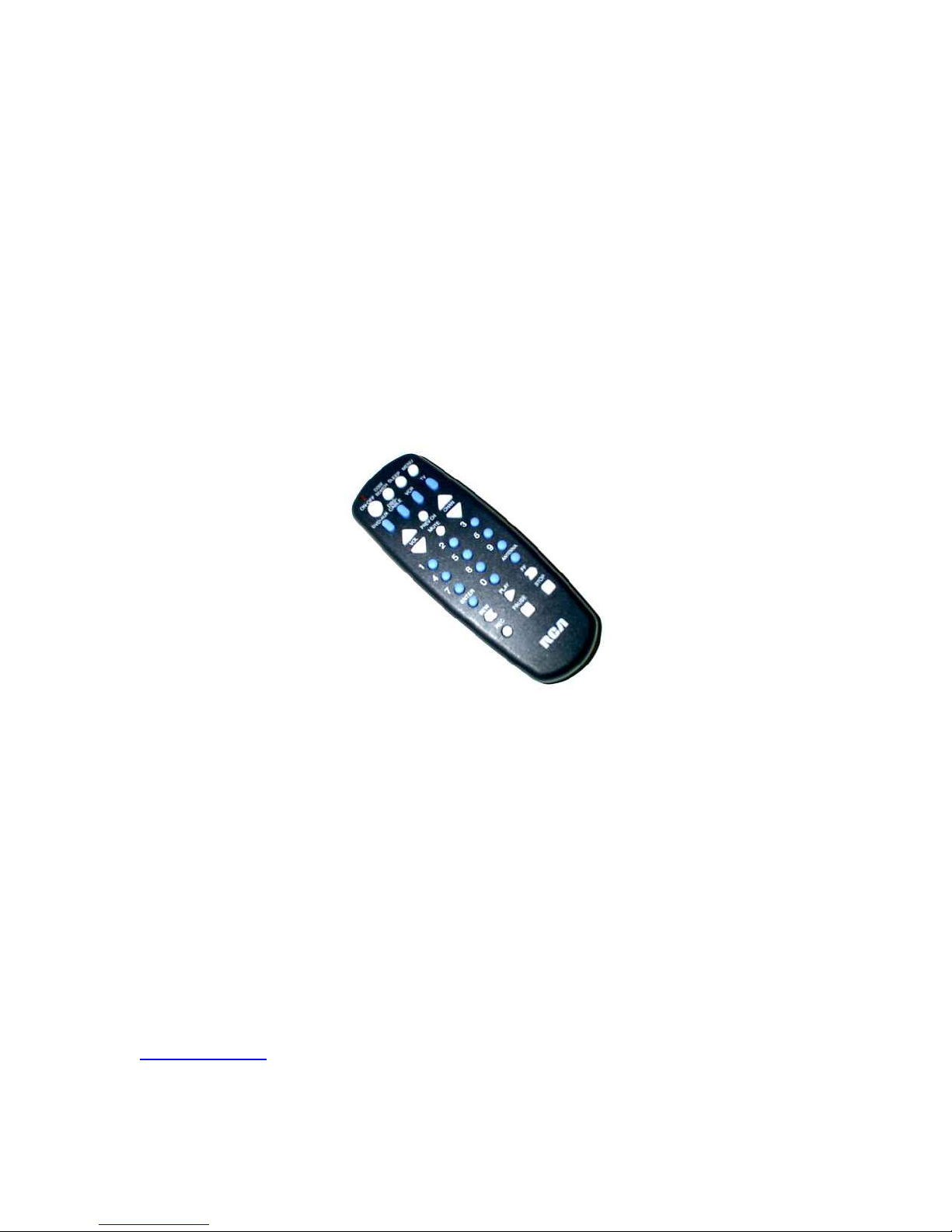
The TV Remote HO Switch
Controller (TVHOSC) system uses
a universal TV remote to control
10 HO turnouts or switches. The
universal TV remote is pictured
below. Press one button to close
the switch and a second button to
open the switch. It is that easy!
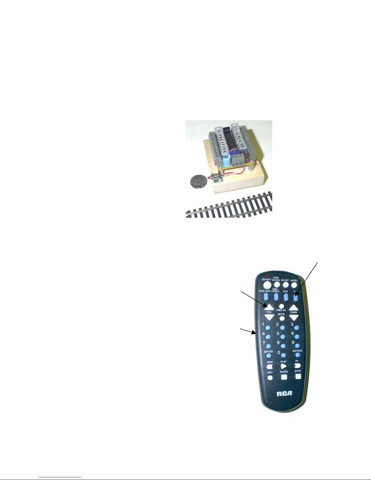
The unit is fairly compact and is
pictured to the right. It is mounted
on a small block of wood and will
easily mount on a train layout. A
quarter coin is also shown.
If you want to control more than
10 switches, two controllers can
used together. That is use one
remote to control the two
controllers.
USING THE REMOTE
The remote is a universal type which has
to be configured for a Sony TV. This
means the remote transmits the codes
that a Sony TV would use.
Instructions are included with the remote
to program it for a Sony TV.
To use the remote point it towards the
TVHOSC unit. There is an IR receiver
mounted on the unit. If you examine the
remote you will notice that there are ten
number buttons 0 to 9. Theses ten
buttons are used to first select a switch.
Press a number button to select a switch
first. Then using the Volume buttons.
Press Vol + to open the switch and Vol –
to close the switch.
The Chan + and Chan – are used to
switch the controller between two
systems
Make sure
the remote’s TV button is pressed too.
NUMBER
BUTTONS
VOLUME
BUTTONS
TV
Page 3

3
The included remote is a universal type which has to be configured for a Sony
TV. You can in fact use any universal remote programmed for a Sony TV. You
must also have the TV button pressed to tell the remote to use TV codes. Most
universal remotes can control several devices such as a TV, VCR, and DVD.
You want to set the remote for a TV.
To use the remote point it towards the TVHOSC unit. There is an IR receiver
mounted in the center, on one end, on the unit (See below). You will soon
discover that the remote signals will bounce off the ceiling and walls and will
easily find their target (the TVHOSC unit).
SETTING the TIME DELAY
A variable resistor control is located on the main circuit board. This blue control
sets the time delay or the amount of time that power gets applied to a switch.
If power is applied to a switch for too long then the switch gets hot and may even
eventually start to melt. If power isn’t applied long enough the switch will not
operate correctly. You want to find the mid-point.
IR
RECEIVER
Page 4

4
You want to apply power to a switch for just long enough so the switch switches.
Once this blue control has been set, the unit will keep using this setting in
applying power to all switches connected to the unit.
The unit comes with the blue dial of the pot, set in its center position. The term
pot is short for potentiometer. It is a variable resistor. Looking at the picture
above, turning the blue dial clockwise decreases the time and counterclockwise
increases the time.
You will discover that there is a screwdriver slot in the center of the control. A
small 1/8 inch flat blade screwdriver is best to use when adjusting this blue dial.
Care must be taken not to turn the blue control too far. It will not
turn or rotate
continuously. The unit is shipped with the control in it mid position.
Whenever you make an adjustment to the blue control you must also press the
reset button to cause this new setting to be read by the unit. Adjusting the pot is
largely trial and error. Rotate the pot slightly, press reset and try to control a
switch. When you have found a setting where the switch operates correctly, you
are done.
WIRING THE TVHOSC UNIT
The unit can control 10 switches. Looking at the unit there are two rows of 10
terminals making 20 screw terminals total. If you examine a switch you will see
Page 5

5
3 screws. There is a center common terminal with the other two screws being
attached to the two switch coils. Here is a wiring diagram:
This table shows the connections:
SWITCH
COMMON
COIL
WIRES
1 C 1, 2
2 C 3, 4
3 C 5, 6
4 C 7, 8
5
C
9, 10
6
C
12, 13
7
C
14, 15
8
C
16, 17
9
C
18, 19
10
C
20, 21
The C wire is common to all the switches. The C terminal is actually connected
to the B terminal on the main circuit board.
C
1 2 3 4
C B A
1
2
3
4
5
6
7
8
9
10
21
20
19
18
17
16
15
14
13
12
IR REC
TO AC
ACCESSORY
POWER
SWITCH 1
SWITCH 2
SWITCH 3
SWITCH 4
C SCREW
COILS
TO COMMON
TERMINAL ON
ALL SWITCHES
TO
REMAINING
SWITCHES
Page 6

6
The lengths of wire used to connect the switches should be kept as short as
possible. Use at least 22 gauge wire. The local train club has such a large
layout that they use 14 gauge wire to connect their switches. As the wire gauge
number gets smaller, the wire gets larger.
Current, Current, Current….
Switches (or turn-outs as they are called) consume an enormous amount of
current. A typical Atlas switch consumes 2 amps of current when switching. At a
local train club where they use switch machines, the current was measured and
found to be 3 amps!
With this much current flowing it is no wonder why these switches get hot if the
power is applied too long.
EXPANSION
If you want to control more than 10 switches, two controllers can used together.
That is use one remote to control the two controller boards.
There would be a high controller and a low controller. Select the high controller
using the Channel + button and low controller using the Channel - button.
NOTES
 Loading...