

Page 1
PHOTOFACT*
Folder
RCA
VICTOR MODELS
(CH.KCS32,
A,
B, C, &
8TK29,
Radio
Ch.
8TR29
RK135,
A)
VERT.
HORIZ.
HOLD
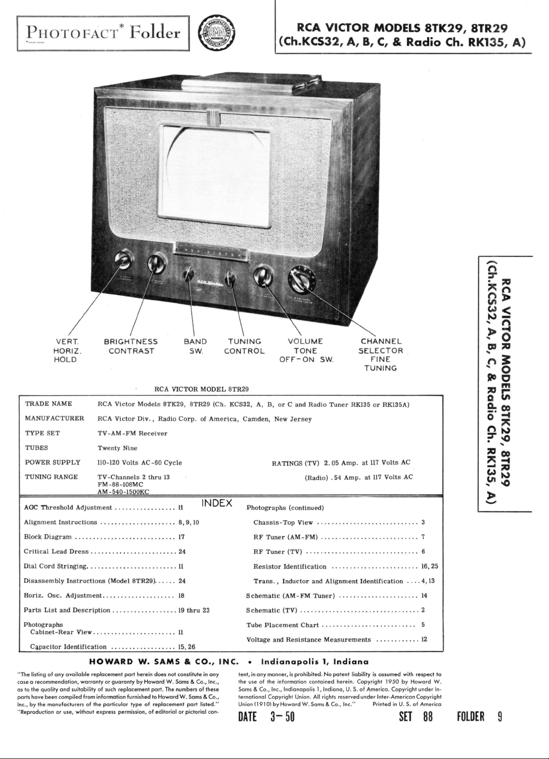
TRADE
NAME
RCA
MANUFACTURER
TYPE
SET
RCA
TUBES
POWER
SUPPLY
TUNING
RANGE
AGC
Threshold
Alignment
Block
Diagram
Critical Lead
Dial
Cord Stringing
Adjustment
Instructions
17
Dress
24
11
Disassembly Instructions
Horiz.
Osc.
Adjustment
Parts
List
and
Description
Photographs
Cabinet-Rear
Capacitor
View
Identification
HOWARD
"The
listing
of any
case a recommendation, warranty
as
to the
parts
have
Inc.,
by the
"Reproduction
available replacement part herein does
quality
and
suitability
been compiled from information furnished
manufacturers
or
use,
of the
without
express
BRIGHTNESS
CONTRAST
RCA
VICTOR
Victor Models
Victor
TV-AM-FM
Twenty
Nine
110-120
Volts
TV-Channels 2 thru
FM-88-108MC
AM-540-1500KC
Div.,
Radio Corp.
Receiver
AC-60
8TK29,
Cycle
13
11
8,
(Model
8TR29)
24
18
19
15, 26
W.
SAMS & CO., INC. • Indianapolis
not
or
guaranty
of
such
replacement
particular type
permission,
by
Howard
of
W.
part.
The
to
Howard
replacement
of
editorial
constitute
Sams & Co., Inc.,
numbers
BAND
SW.
TUNING
CONTROL
OFF-ON
MODEL
8TR29
8TR29 (Ch.
of
RATINGS
9,10
thru
11
W.
Sams & Co.,
part
listed."
or
pictorial
KCS32,
America, Camden,
INDEX
23
in any
of
these
con-
tent,
the
Sams & Co., Inc., Indianapolis
ternational
Union
DATE
A, B, or C and
New
Photographs
Chassis-Top
RF
Tuner
RF
Tuner (TV)
Resistor
Identification
Trans. , Inductor
Schematic
S
Tube
Voltage
use of the
(AM-FM
chematic (TV)
Placement Chart
and
in any
manner,
information contained herein. Copyright
Copyright Union.
(1910)
by
Howard
3-50
VOLUME
TONE
SW.
Radio Tuner
Jersey
(TV)
(Radio)
(continued)
View
(AM-FM)
and
Tuner)
Resistance
is
prohibited.
1,
All
W.
Sams & Co.,
CHANNEL
SELECTOR
FINE
TUNING
RK135
or
RK135A)
2.05
Amp.
at 117
Volts
. 54
Amp.
at 117
Volts
Alignment Identification
Measurements
1,
Indiana
No
potent
liability
is
assumed with
Indiana,
rights
U. S. of
reserved
Inc."
1950
America. Copyright under
under
Inter-American
Printed
AC
AC
by
Howard
in U. S. of
SET
3
7
6
16,
25
...
4,
13
14
2
5
12
respect
to
W.
In-
Copyright
America
88
FOLDER
m
9
Page 2
® ®
ccwn
THE
COOPERATION
RECEIVER
MAKES
IT
POSSIBLE
OF THE
MANUFACTURER
TO
BRING
YOU
A
PHOTOFACT
©Howard
*
OF
THIS
THIS
SERVICE
STANDARD
W.
Soms & Co., Inc. 1950
NOTATION
SCHEMATIC
PAGE
2
Page 3
SOUND
IF
AMP
AF
AMP-BIAS
CLAMPER
!3>6AV6
7!
IK)
-^WV
5600^
lg)=»-F
—
i
j
^@]
/'TWTV
1
—
@ > "
^
W
|
@^r
(SP
^
MUF
'500
_^yj
.
-r-
1500
_L
MMF
-=•
I
@
ww
150^
®cr
^B
Page 4
AUDIO
®
OUTPUT
BV6GT
88-9
Page 5
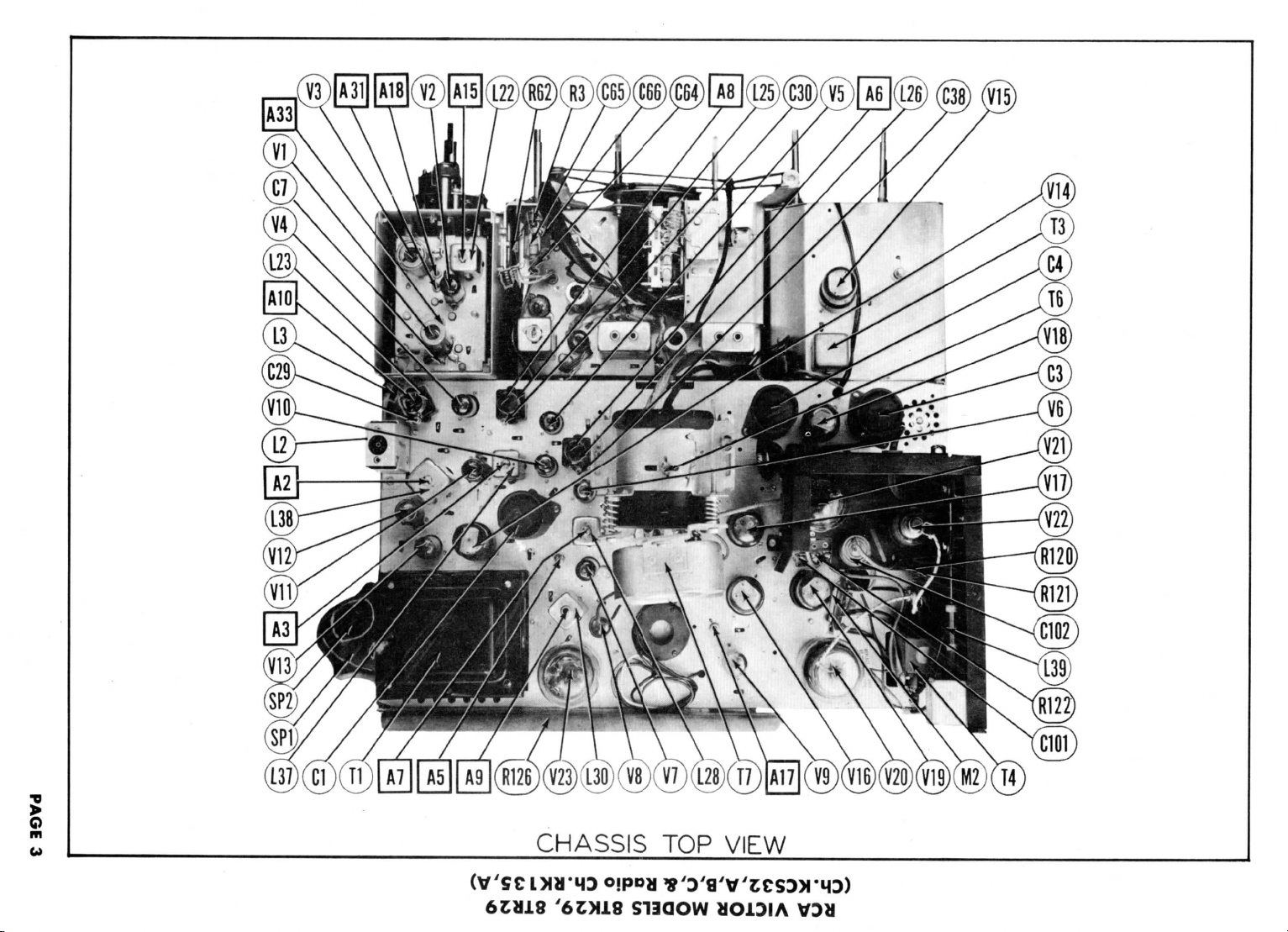
RCA
VICTOR MODELS 8TK29, 8TR29
(Ch.KCS32,A,B,C,& Radio Ch.RKl
35,
A)
M3IA
dOl
SISSVHD
Page 6
o
Page 7
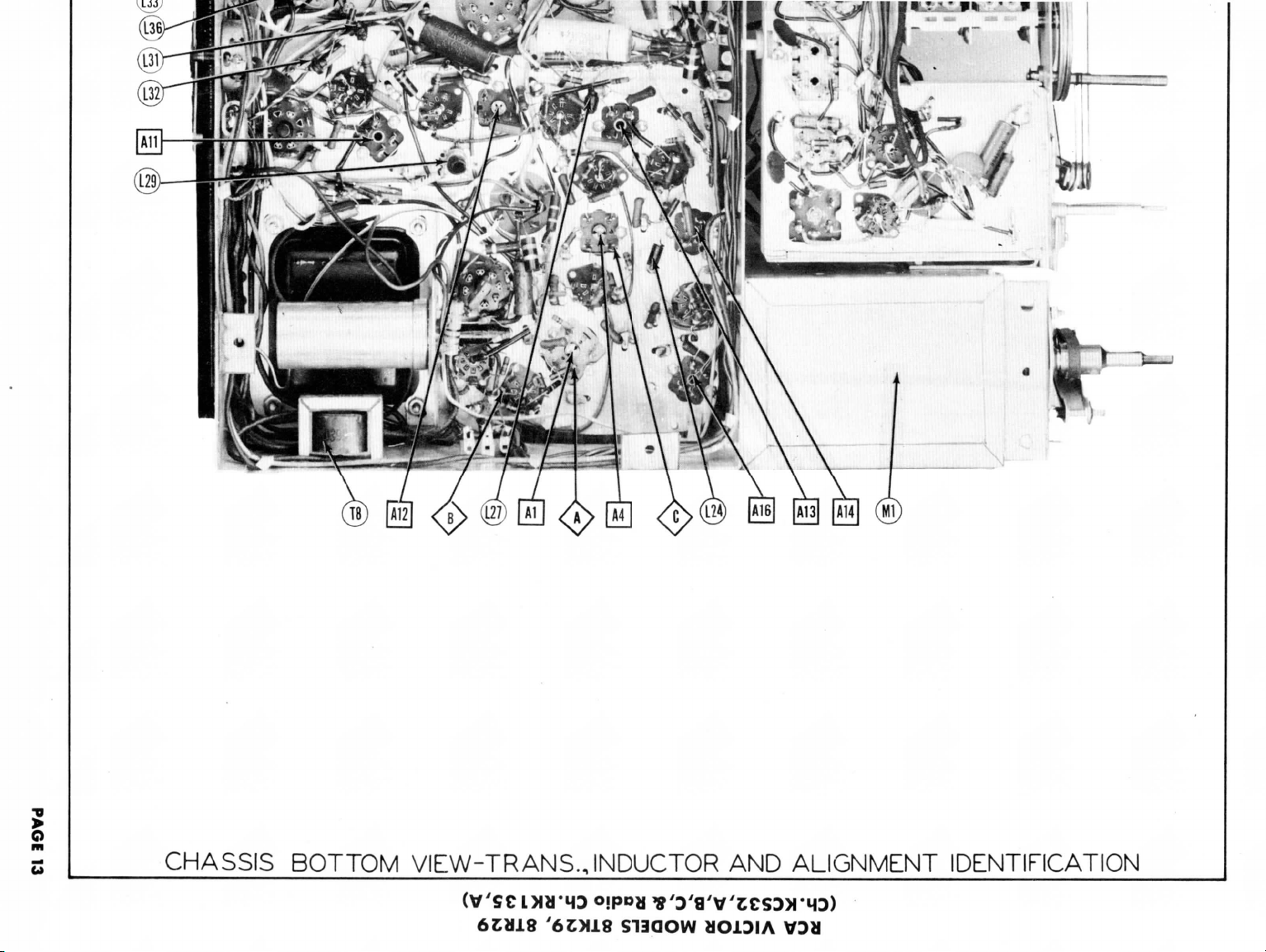
CHASSIS
BOTTOM
VIEW-TRANS.
JNDUCTOR
AND
ALIGNMENT
IDENTIFICATION
'6CX18
S11QOW
HO1DIA
V3H
Page 8
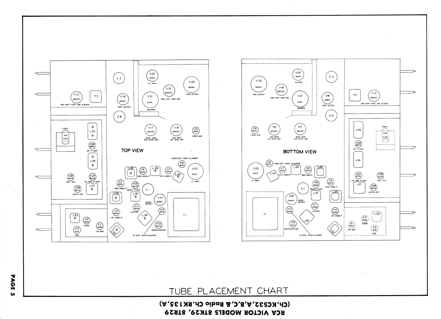
TOP
VIEW
TUBE PLACEMENT CHART
(V'SC
6£U18
LJHTMD
'6OJ18
S13QOW
Page 9
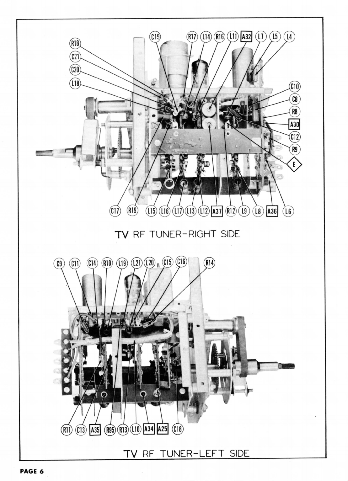
TV RF
TUNER-RIGHT
SIDE
PAGE
6
TV RF
TUNER-LEFT
SIDE
Page 10

AM-FM
IMS)
(ciin)
A
(MI)
TUNER-TOP
(MS)
(Mjo)
VIEW
AM-FM
TUNER-BOTTOM
VIEW
PACE
7
Page 11

Turn
the
function
The
high voltage shock hazard
When
complete
Set the
DUMMY
ANTENNA
.
01MFD
.
01MFD
.
01MFD
Use
frequency
DUMMY
ANTENNA
.
01MFD
.
01MFD
Remove
Connect
Note
that during video
Connect
DUMMY
ANTENNA
Direct
Direct
Direct
Direct
Direct
Direct
Direct
DUMMY
ANTENNA
Direct
Direct
DUMMY
ANTENNA
.
OIMFD
selector
receiver
channel switch
GENERATOR
COUPLING
High
side
of
6AU6
(Vlll.
to
chassis.
High
side
of
6AU6
(V10).
to
chassis.
modulated signal
GENERATOR
COUPLING
High
side
of
6AU6
(V10).
to
chassis.
"
V15
from
its
the
negative lead
the
synchronized sweep voltage
GENERATOR
COUPLING
High
side
tube
shield floating over
mixer tube
side
to
chassis.
GENERATOR
COUPLING
High
side
tube
shield floating over
mixer tube (V2).
side
to
chassis.
GENERATOR
COUPLING
High
side
of
12AU7(V9).
to
chassis.
TV
ALIGNMENT
to
"television",
may be
eliminated
is to be
blank position between channels
SIGNAL
GENERATOR
FREQUENCY
(Grid)
21.25MC
(Unmod.)
side
(Grid)
side
SOUND
with
60
•*
SWEEP
GENERATOR
FREQUENCY
(Grid)
21.25MC
(450KC
side
volt battery
the
common
from
SIGNAL
GENERATOR
FREQUENCY
21.
(Unmod.
Low
27.
19.75MC
22.
24.6MC
22MC
25.9MC
GENERATOR
FREQUENCY
25MC
(10MC
Low
(Grid)
side
Sweep)
SWEEP
GENERATOR
FREQUENCY
4.
SMC
(40(K
alignment
to the
SIGNAL
to pin 1
Low
to pin 1
Low
SWEEP
to pin 1
Low
socket.
IF
SIGNAL
to
ungrounded
(V2).
-
"
SWEEP
to
ungrounded
SWEEP
to pin 2
switch
of a 4. 5
alignment
Low
ALIGNMENT INSTRUCTIONS
INSTRUCTIONS—
(maximum counter-clockwise).
by
removing
performed,
SOUND
"
IF
modulation
Sweep)
it can
IF
ALIGNMENT USING
CHANNEL
See
note
under prealignment.
"
"
ALIGNMENT USING
and
MARKER
GENERATOR
FREQUENCY
21.
25MC
"
to pin 5 of the
lead
of
the
signal
CHANNEL
See
)
note
under
alignment
"
MARKER
GENERATOR
FREQUENCY
21.95MC
24.
BMC
21.25MC
22.
IMC
25MC
25. 7 SMC
26.
SMC
MARKER
GENERATOR
FREQUENCY
Not
used
25MC
25MC
SMC
SWEEP
Mod.)
READ
the
horizontal
most conveniently
2 and 13.
DC
Probethru 1 Meg.
o
Point<Q>
o
chassis.
DC
Probe
Common
)C
Probe
o
Point^^
o
chassis.
FM
450KC
sweep.
CHANNEL
See
under
alignment
VIDEO
IF
socket
VTVM
is at
generator
DC
leads
pre-
CHANNEL
See
under
alignment
4. 5MC
TRAP
CHANNEL
Any
CAREFULLY
CONNECT
SIGNA . GENERATOR
Note
pre-
ALIGNMENT
of V5,
-120
to the
CONNECT
Probe
across
"
"
"
note
pre-
ADJUSTMENT
BEFORE ATTEMPTING ALIGNMENT
oscillator
be
performed
AM
SIGNAL GENERATOR
VTVM
Low
side
to
Point^)
to
chassis.
thru 1 Meg.
Common
Use 120 ~ sawtooth voltage
CONNECT
SCOPE
Vert.
Amp.
33KJJ
to
Point^/
Low
side
-t.
Amp.
Low
side
€
ssis.
connect
the
volts
with
respect
horizontal input
VTVM
and
common
R40.
CONNECT
SCOPE
Vert.
Amp.
<Q>
Low
side
sis.
CONNECT
SCOPE
Vert.
Amp.
(Grid)
of
Low
side
tube
(V19).
in the
ADJUST
Al,
A2
Al
A3,A4
AND
OSCILLOSCOPE
thru
to
chassis.
to
Point
to
positive lead
to
chassis.
of the
ADJUST
A5,A6
A7,A8
A9, A10
All
A12
A13
A14
to
Point
to
chas-
to pin 2
picture tube.
to
chassis.
order
AND
VTVM
Detune
A2
for
Adjust
reading will
setting.
Adjust
in
scope
ADJUST
A3.A4
A1.A2
to
chassis.
Avoid grounding
oscilloscope
Adjust
Adjust
ADJUST
A15.A16
ADJUST
A17
given.
Al
several
maximum deflection.
for
zero
for
maximum deflection.
for
for
for
MINIMUM
for
maximum deflection.
REMARKS
turns counter-clockwise. Adjust
reading. A positive
be
obtained
on
either
side
horizontal deflection.
REMARKS
Adjust
for
maximum amplitude
symmetry
as per Fig 1.
Adjust
Al so 21.
25MC
crossover
lines
for
maximum amplitude
of
crossover
or
horizontal
deflection.
"
"
"
"
Shunt
the
primarys
and
L30
(All thru A14) with
resistors.
Adjust
curve
similar
shown.
Remove
all
for
response
as
shown.
If
A16
for
proper
Adjust
for
minimum
scope,
If a
a
VTVM
with
used.
This
maximum
vertical
observing a test
occurs
as per Fig 2.
lines.
Continue with
touching
the
deflection.
REMARKS
REMARKS
of
L25, L26,
A15 and A16 for
to Fig 3
with
300n
shunting
similar
to Fig 4
necessary
response.
REMARKS
40tK
wide band scope
suitable
RF
trap
may be
wedge definition while
pattern
and
of the
at
and
straightness
VTVM
300SJ
markers
resistors.
retouch
response
is not
probe
adjusted
from
a TV
negative
correct
and
center
Adjust
step
case.
L28
carbon
response
with
markers
All
on
available
may be
for
station.
of
A2
4.
as
Check
thru
PAGE
8
FIG
FIG.
FIG.
4
Page 12

The
signal
Complete
rected
in one
DUMMY
ANTENNA
Twol20fi
carbon
res.
The
antenna
Alignment
Remove
Remove
DUMMY
ANTENNA
Two
12
carbon
res.
"
TV
generator
output
alignment
SIGNAL
in
each lead.
section
attempted
IF
SWEEP
120J2
"
lead should
may not be
terminals
of
this
Amp. (V4).
in
each
oscillator
step
using A18.
GENERATOR
COUPLING
Across
antenna
with
120fi
and RF
should
not be
the
4. 5 volt battery used during video
the
first video
GENERATOR
Across
minals
lead.
COUPLING
antenna ter-
with
On
ALIGNMENT
OSCILLATOR
terminated with
if
all
CHANNEL
13
12
11
10
9
8
7
6
5
4
3
2
very
stable
definitely
alignment
MARKER
GENERATOR
FREQUENCY
175.
25MC
179. 7 SMC
205.
25MC
209.75MC
175.
25MC
179. 7 SMC
181.
25MC
185.75MC
187.25MC
191.75MC
193.
25MC
197.
75MC
199.
25MC
203. 7 SMC
211.
25MC
215.75MC
83.25MC
87.75MC
77.25MC
81.
75MC
67.25MC
71.
75MC
61.
25MC
65.75MC
55.25MC
59. 7 SMC
ANTENNA
is
are
IF
its
characteristic
channels seem
DC
Common
and
will
known
and
replace
CHANNEL
7
12
7
8
9
10
11
13
6
5
4
3
2
SIGNAL
GENERATOR
FREQUENCY
215.75MC
(Unmod.)
209. 7 SMC
203. 7 SMC
197.
191. 7 SMC
185.75MC
179. 7 SMC
87.75MC
81.75MC
71.
65.75MC
59.
receiver
unless
GENERATOR
FREQUENCY
177MC
(10MC
Sweep)
207MC
(10MC
177MC
(10MC
183MC
(10MC
189MC
(10MC
19
SMC
(10MC
201MC
(10MC
213MC
(10MC
85MC
(10MC
79MC
(10MC
69MC
(10MC
63MC
(10MC
57MC
(10MC
be
necessary,
75MC
75MC
75MC
they
SWEEP
SWP)
SWP)
SWP)
SWP)
SWP)
SWP)
SWP)
SWP)
SWP)
SWP)
SWP)
SWP)
INSTRUCTIONS
ALIGNMENT
Probe
AND RF
to be out of
CONNECT
VTVM
to
Point<^>
to
chassis.
not
normally
it
with
ALIGNMENT
Vert.
^^>
sis.
impedance, usually
to be
off
frequency approximately
ADJUST
A18
A19
A20
A21
A22
A23
A
24
A25
A
26
A27
A28
A29
require
volts battery
CONNECT
SCOPE
Amp.
to
side
to
"
alignment
Point
chas-
alignment.
3. 5
Low
.
50
Adjust
reading
setting.
ADJUST
A30,
A32.A33
A30
A34,
A35,
A36,
A3 7
CCONTJ
ohms.
the
for
zero
will
be
obtained
in the
field.
Adjust
A31
similar
Adjust
minimum
in
Fig
Check
and
7. If
channel,
A34
with channel
channel. Recheck
to
see
effected.
Adjust
6
with markers above 90%.
Check
markers
make
with
channel
Recheck
they
have
same
amount,
they
REMARKS
reading. A positive
on
either
REMARKS
for
flat-topped
to Fig 5
A30 for
slope
6.
for
response
markers
make
that they have
for
response curve
for
response
are
slight
all low
not
with
maximum
of top of
similar
are
slight
selector
all
similar
below
80% on any
adjustment
selector
band channels
been
seriously
response
markers
below
adjustment
high
not
set for
may be
cor-
and
negative
side
of the
curve
above 90%.
response
curve
as
shown
to
Figs.
80% on any
of A31
set for
that
band
channels
been seriously
similar
to Fig 6. If
channel,
of A35
thru
that channel.
to see
effected.
correct
and
5, 6,
to Fig
A38
that
thru
Ki
^
:>§
09
50
_
JO
I-
a
*/»
FIG.
5
FIG.
6
FIG.
7
PAGE
9
Page 13

RADIO
ALIGNMENT INSTRUCTIONS
ALIGNMENT
INSTRUCTIONS
S5^ASEltff«53MSfe^
aUfo'setpoint.er
Volume
insulated
DUMMY
ANTENNA
.
01MFD
20
21
200MMF
22
200MMF
200MMF
23
Connect
on
the
Alternate
secondary
process
DUMMY
ANTENNA
24
.
01MFD
25
.
01MFD
26
.
01MFD
Use
frequ
DUMMY
ANTENNA
24
Direct
25
DUMMY
ANTENNA
27
270SZ
carbon
res.
28
control
alignment
High
minal.
two
matched
schematic.
loading
of the
is
repeated
High
of
6AU6
to
chassis.
ency modulated
High
tube
converter
side
High
grounded antenna
Low
turn tuning
side
should
be at
screwdriver
SIGNAL
GENERATOR
COUPLING
to
antenna ter-
Low
side
cap
maximum
to
chassis.
"
"
100KO
(t 1%)
is
used
on the
same transformer
for
each
transformer.
SIGNAL
GENERATOR
COUPLING
side
to pin 1 (Grid)
(V21).
Low
"
signal
SIGNAL
GENERATOR
COUPLING
side
to
ungrounded
shield floating
to
chassis.
side
side
tube
(V25).
SIGNAL
GENERATOR
COUPLING
thru
270J1
terminal.
to
chassis.
over
fully c osed
for
adjusting.
resistors
transformers
is
being
side
with
60 -
Low
to un-
and
set
position.
SIGNAL
GENERATOR
FREQUENCY
455KC
400-
Mod.)
1620KC
1400KC
600KC
in
during
adjusted.
SIGNAL
GENERATOR
FREQUENCY
10.
7MC
(Unmod.
FM
IF
modulation
SIGNAL
GENERATOR
FREQUENCY
10.7MC
(450KC
Sweep)
SIGNAL
GENERATOR
FREQUENCY
106MC
(Unmod.
90MC
po
nter
to
Output
of
signal
BAND
SWITCH
POS.
AM
second
pos.
clockwise)
"
FM = ALIGNM
series
from point
FM IF a
When
BAND
SWITCH
POS.
FM
)
(third
position
CW)
"
ALIGNMENT USING
and
450KC
BAND
SWITCH
POS.
FM
(third
pos.
CW)
BAND
SWITCH
POS.
FM
)
"
READ
last
reference
generator
Tuning gang
fully
Tuning gang
fully
Tune
output
600KC
;NT
USING
ignment,
the
primary
Tuning
fully
sweep.
Point
interference
106MC
Tune
deflection.
CAREFULLY
mark
should
RADIO
DIAL
SETTING
closed
open
for
max.
AM
SIGNAL GENERATOR
to<^>to
chassis.
that
is, the
is to be
RADIO
DIAL
SETTING
gang
open
FM
SIGNAL
Use 120 -
RADIO
DIAL
SETTING
of
non-
RADIO
DIAL
SETTING
for
max.
BEFORE
ATTEMPTING ALIGNMENT
at
low
frequency
be no
higher
OUTPUT
METER
Across
voice
coil
"
The
junction
primary
CONNECT
VTVM
Probe
chassis.
Probe
Poim$>
Probe
chassis.
sawtooth
CONNECT
SCOPE
to
chassis.
to
chassis.
CONNECT
VTVM
Probe
to
chassis.
of
the
680J3
to
Common
to
Common
to
Common
AND
voltage n scope
to
Low
to
Low
to
Low
adjusted,
DC
Point^y
to
DC
Point^^>
to
DC
Point<£)
to
GENERATOR
Vert. Amp.
Point<£>
side
Vert. Amp.
Point<^>
side
DC
PoinU^
side
end of
dial.
neces
ADJUST
A38,
A39,
A40,
A41
sary
Adjust
than
A42
A43
Adjust
A44,
21,
A45
can
AND
VTVM
of
these
two
each transformer
resistor
is
ADJUST
A46
Adjust
A47
Adjust
negative
side
Use
A48,
A49,
Adjust
A50,
A51
OSCILLOSCOPE
for
ADJUST
A46,
Disconnect
A48,
just
A49,
as per Fig 9. .
A50,
A51
A47,
Reconnect
A46
10.
as per Fig 10.
maximum
crossover
ADJUST
A52,
Set A52 to
A53
compress
flection, then adjust
flection
A54
Expand
deflection. Repeat
further
to
obtain
an
output
for
maximum output.
for
maximum output.
22,
and
23
until
be
resistors
is
used
of the
alternate
horizontal deflection
for
7MC
no
made.
is
alignment
shunted with
to
shunt
the
for
maximum deflection.
for
zero
reading. A positive
reading
will
correct
loading
for
maximum deflection.
stabilizer
maximum amplitude
capacitor
occurs
at
Slightly retouch
amplitude
lines.
Continue with
maximum
turns
of A53 for
.
or
compress
improvement
reading.
Use an
REMARKS
Repeat
further improvement
point^fXs
680
ohms
while
secondary.
REMARKS
be
setting.
REMARKS
(C107).
center
and
REMARKS
capacity.
A52 for
coil
steps
can be
obtained
as
explained
capacitor
and
Adjust
of
crossover
straightness
maximum
maximum
turns
27 and 28
made.
This
on
(C107).
symmetry
A46 for
step
Expand
for
steps
shown
the
and
either
above.
Ad-
A47 so
lines
of
27.
or
de-
de-
maximum
until
no
PAGE
1O
FIG.
9
FIG.
10
Page 14

WIDTH
HORIZ.
LIN.
_
r<*
8?
HEIGHT
ture.
may
of
bend
Turn
Turn
Turn
Turn
already
Turn
FOCUS
AGC
the set on and
the
contrast
the AGC
threshold
the AGC
threshold
be
there.
disappears.
the
contrast
VERT.
LIN.
CABINET-REAR
THRESHOLD
tune
in a
local
TV
station.
control
to
maximum
clockwise.
control
to
maximum
control clockwise until
Then turn
control
the AGC
to
approximately
threshold control slowly counter-clockwise until
ADJUSTMENT
counter-clockwise, a bend
there
is a
very slight bend,
the
center
of its
range.
VIEW
may
The
picture should
appear
or
slight change
in the
be of
upper
the
part
of the
slight
proper
of the
bend
which
bend,
or
contrast.
pic-
change
"r
0
t/»
9:00
o
.01
DIAL
CORD
STRINGING
PAGE
11
Page 15

o
Tube
Item
V 1
6AG5
V
2
6AG5
V
3
6
16
V
4
6AG5
V
5
6AG5
V
6
6AG5
V7
6AG5
V
8
6AL5
V9
12AU7
V
10
6AU6
Vll
6AU6
V
12
6AL5
V13
6AV6
V
14
6V6GT
V
15
6SN7GT
V
16
6SN7GT
V
17
6SN7GT
VIS
6K6GT
V
1 9
6SN7GT
V20
6BG6G
V21
5V4G
V22
1B3GT
V23
5U4G
V24
10BP4
V.25
6J6
V25
6J6
6BA6
V26
V27
6AU6
6AL5
V28
V29
6AV6
§
TAKEN WITH VACUUM
.
MEASURED FROM
1
MEASURED FROM
«
TAKEN
t
TAKEN
IN AM
IN FM
Pin
1
.5VDC
0V.
68VDC
-.1VDC
0V.
0V.
0V.
..2VDC
.105VDC
0V.
-.3VDC
ov.
-.6VDC
OV.
.-55VDC
T37VDC
-1.1VDC
OV.
.-2.4VDC
OV.
OV.
OV.
OV.
105VDC
90VDC
-.1VDC
OV.
.1VDC
OV.
PIN 6 OF
PIN 6 OF
POSITION.
POSITION.
OV.
OV.
68VDC
.4VDC
.6VDC
.4VDC
1.2VDC
1-1.5VDC
.-3.1VDC
OV.
OV.
-.6VDC
OV.
OV.
.90VDC
.320VDC
H132VDC
140VDC
OV.
.100VDC
OV.
290
«
DO NOT
250
.80
100VDC
65VDC
OV.
OV.
-.5VDC
OV.
TUBE
Pin
V15.
VOLTAGE READINGS
2
Pin
OV.
OV.
6. 3 VAC
OV.
6. 3 VAC
OV.
6. 3 VAC
OV.
..4VDC
OV.
OV.
1.3
VAC
OV.
.190
.OV.
150VDC
OV.
..320VDC
.-17
.8. 8 VDC
VDC
OV.
MEASURE.
OV.
VDC
PIN 10
VDC
270VDC
OV.
OV.
OV.
OV.
6. 3 VAC
6. 3 VAC
VOLTMETER.
V19.
3
VDC
VDC
Pin
4
6 . 3
VAC
6. 3 VAC
OV.
6. 3 VAC
OV.
6.3VAC
OV.
6. 3 VAC
6. 3 VAC
6. 3 VAC
6. 3 VAC
6. 3 VAC
6. 3 VAC
.
200VDC
1-15VDC
140VDC
T-1.5VDC
.3
20
VDC
.-42VDC
.-.7
VDC
235VDC
390VAC
PIN 11
90VDC
6. 3 VAC
6.3VAC
6. 3 VAC
6. 3 VAC
OV.
OV.
Pin
5
145VDC
11 5 VDC
5-3.3VDC
95VDC
100VDC
62VDC
155VDC
HOV.
6 . 3V
AC
105VDC
110VDC
OV.
.4VDC
.OV.
T57VDC
1132VDC
1270VDC
.OV.
.165VDC
.OV.
OV.
OV.
PIN 12
6. 3 VAC
§-9.5VDC
J-5.8VDC
185VDC
175VDC
-.2VDC
-.3VDC
Pin
140VDC
115VDC
§-3.6VDC
9 5
VDC
100VDC
100VDC
115VDC
OV.
.
200
10
5 VDC
60VDC
OV.
.4VDC
.112VDC
10V.
H50VDC
11. 8 VDC
.30VDC
.OV
.OV.
.8. 8 VDC
235VDC
390VAC
OV.
OV.
10
5 VDC
140VDC
OV.
-.3VDC
1.
DC
ohms
ohms.
2. Pin
tion
3.
Measured
mon
VOLTAGE
6
VDC
Voltage
per
numbers
on
bottom
negative
AND
Pin
7
OV.
OV.
.2VDC
.4
VDC
.6VDC
.4
VDC
1.2VDC
.-.1VDC
.115VDC
.6VDC
OV.
-.5VDC
80VDC
6. 3 VAC
6. 3 VAC
6. 3 VAC
6. 3 VAC
6. 3 VAC
6. 3 VAC
6. 3 VAC
OV.
OV.
OV.
OV.
.6VDC
1.1VDC
-.2VDC
OV.
measurements
volt;
AC
Voltage
are
counted
of
socket.
values
are
unless
RESISTANCE
Pin
8
Pin
9
.115VDC
.11
OV.
OV.
OV.
.45VDC
.35VDC
OV.
.260
290VDC
250
NOTE:
measured
in a
from
otherwise
OV.
VDC
TOP CAP
VDC
VDC
AGC
THRESHOLD CONTROL
FOR
THESE
are at
20,000
at
1,000
clockwise
direc-
socket
pin to
com-
stated.
MEASUREMENTS.
Item
V
1
V
2
V
3
V
4
V
5
V
6
V7
V
8
V9
V
10
V 1 1
V
12
V
13
V
14
V
15
V
16
V
17
V
18
V
19
V20
V21
V22
V23
V24
V25
V25
V26
V27
V28
V29
4.
Line
voltage maintained
age
readings,
5.
Front
panels
6.
Where
setting
of the
and
maximum
MEASUREMENTS
Tube
6AG5
6AG5
6J6
6AG5
6AG5
6AG5
6AG5
6AL5
12AU7
6AU6
6AU6
6AL5
6AV6
6V6GT
6SN7GT
6SN7GT
6SN7GT
6K6GT
6SN7GT
6BG6G
5V4G
1B3GT
5U4G
10BP4
6J6
6J6
6BA6
6AU6
6AL5
6AV6
SET AT
readings
controls
may
service
readings
Pin
1
150KJ2
lOOKn
fllKn
6.5KS2
10KS1
5.5Kn
.in
.ion
5.5KSJ
.in
22Kn
on
10
Meg.
Inf.
.2. 5 Meg.
160Kn
IMeg.
Inl.
. I Meg.
Inf.
Inf.
Inf.
Inf.
on
t27Kn
f27Kn
2. 5 Meg.
.20
3.3Kn
on
MAXIMUM
at
117
set at
minimum.
vary
according
controls,
are
volts
both
given.
on
on
tiiKn
39n
een
39n
ison
13.9
.5.6Kn
on
on
lOOKn
on
on
fl.SMeg.
#270Kn
tsoicn
ti6Kn
on
#180Kn
on
200Kn
Inf.
eicn
2. 2 Meg.
ti5Kn
tisicn
on
on
40Kn
on
minimum
Pin
2
Meg.
for
to the
volt-
RESISTANCE
Pin
on
on
.in
on
.in
on
.in
on
.loon
on
on
2n
on
tsicn
.on
330KTC
on
ti.sicn
.300Kn
.sen
Inf.
Inf.
Inf.
PIN 10
56Kn
on
on
on
on
.in
.in
READINGS
Pin
4
Pin
ts.sicn
t2Kn
lOOKn
f2.5Kn
t2.5Kn
t8Kn
t8Kn
TOT!
.in
f2.2Kn
t2Kn
200Kn
150Kn
.470Kn
L24Kn
t7.5Kn
t220n
.2.2
tisoKn
.1
Inf.
Inf.
Inf.
PIN 12
.in
18KS2
18KSJ
tiooon
ti.eicn
Inf.
350Kn
5
Meg.
Meg.
Pin
6
ti.SKn
t2Kn
lOOKn
t2.5Kn
t2.5Kn
t2Kn
t2Kn
on
tMKn
f2.2Kn
f23Kn
on
isoxn
ion
ion
lOOKn
ie.8Kn
.5Kn
.on
.on
.sen
tseon
Inf.
i.2Kn
6. 5 Meg.
6. 5 Meg.
t27Kn
tieicn
on
2. 6 Meg.
|
MEASURED
f
MEASURED
.
MEASURED FROM
f
MEASURED
*
TAKEN
t
TAKEN
Pin
on
on
47n
39n
esn
39n
ison
.5.6Kn
3.3Kn
82n
on
looicn
tssoxn
•in
.in
.in
.in
.in
.in
.in
Inf.
Inf.
Inf.
on
on
esn
i2on
Inf.
on
7
IN AM
IN FM
Pin
.i2Kn
.490n
on
on
on
.7.7Kn
.2.7Kn
on
tiOKn
200Kn
Inf.
6KSJ
FROM
FROM
FROM
POSITION.
POSITION.
3
.in
.in
on
.in
on
.in
on
.in
.in
.in
.in
.in
.in
f2.6Kn
.sooKn
11KSJ
f3.9Meg.
tl.SKn
.250Kn
.isoxn
tseon
Inf.
i.2Kn
PIN 11
12KO
.in
.in
.in
.in
on
on
8
on
TOP CAP
|2p_pn
TOP CAP
#3
PIN 8 OV
PIN 8 OF
PIN 6 OF
PIN 6 OF
Pin
son
9
V21.
VIS.
V23.
V19.
Page 16

TI
>
o
IF=455
IF=I0.7
KC AM
MC
FM
AM-FM
®.s,~
,-^vvv-,
®
®
—oo J vW-«
"D
TUNER SCHEMATIC
88-9
Page 17

9L
lOVd
Page 18

o
5
CHASSIS
BOTTOM
(V'SC
DIH'MD
6CU18
VIEW-CAPACITOR IDENTIFICATION
'60J18
S13QOW
MO1DIA
Page 19

^
O
a.
Page 20

•0
>
O
to
in
CHASSIS
BOTTOM
VIEW-RESISTOR
IDENTIFICATION
(V'SC
IHITHD
'6CX18
S13QOW
MOiDIA
V3d
Page 21

RCA
VICTOR MODELS
(Ch.KCS32,A,B,C,&
8TK29,
8TR29
Radio Ch.RKl
>oo~ia
35,A)
1TA
ilA
9TA
Z/l
Z/l
2/T
'das
ONAS
'dWV
'das
ONAS
PU2
ONAS
1=
ETA
1/1
HadWVIO
STA
Zl\
00V
9TA
2/T
I
'iOaU
SVI3
00V
Page 22

HORIZONTAL
OSCILLATOR ADJUSTMENTS
HORIZONTAL
station
Just
notice
drive
or
HORIZONTAL
switch
diagonal
(B5) slightly clockwise.
bars present
HORIZONTAL OSCILLATOR WAVEFORM ADJUSTMENT
clockwise. Adjust
raster.
control
scope
(If
In
ceptibility
oscillator
triggering
HORIZONTAL OSCILLATOR ADJUSTMENTS CHECK
slowly turn
synchronizes.
turn
at the
to
ture. Retouch
FREQUENCY ADJUSTMENT
Connect a Jumper
and,
1.
Turn
out of
2.
Turn
the
picture width
(B3),
B4
required adjustment repeat step 1 above.
LOCKING RANGE ADJUSTMENT
Turn
the
to
another channel
bars
If
more than 9 bars
Turn
the
Remove
the
Connect
the low
one
should
necessary,
This
adjustment must
amplitude than
Is
of the
Turn
the
If
more than 3 bars
B5
slightly
pull-in point. Repeat
Turn
the
the
extent that
across
terminals
If
possible, sync
horizontal hold control
sync
and the
horizontal
the
hold control approximately a quarter
and
width
(B3)
and
horizontal linearity
horizontal hold control fully
and
that appear Just before
are
present Just before synchronization, turn
If
hold
control counterclockwise
at the
pull-in
point. Repeat
Jumper across terminals
B6
with a non-metallic screwdriver until
capacity
quarter
be
similar
while
the
to
noise
overstablllzed,
oscillator
horizontal hold control fully
the
hold control clockwise
counterclockwise.
horizontal hold control fully clockwise.
the
B6
until
probe
of a
turn
to
Fig
making
this
be
carefully made
sharp peak,
pluses.
are
present, turn
horizontal blanking
this
"C" and
the
picture
fully
blanking appears
linearity.
back again. Slowly turn
the
less than 7 bars
"C" and "D" of
of an
from
the
8.
Adjust
adjustment turn
the
oscillator drift becomes greater
However,
the
pull-in range Inadequate,
as the
horizontal hold control approaches
Momentarily remove
this
procedure until 3 bars
condition
If the
oscilloscope
clockwise
If
and
exists.
"D"
of
the
horizontal oscillator
and
proceed
as
follows:
clockwise. Adjust
width
(B4)
counterclockwise.
picture "syncs".
are
present, turn
and
momentarily Interrupt
this
procedure until
position
B6
until
the
the
to
assure correct circuit operation.
the
broad peak
counterclockwise.
note
the
number
B5
slightly clockwise.
bar
appears
the
Frequency Adjustment
as a
vertical
of a
turn from
and
linearity
controls until
the
T3.
Turn
to
terminal
until
broad
hold control
Is
the
are
The
picture should
as a single vertical
bar.
the
Is
the
Remove signal momentarily
hold control clockwise
B5
slightly
the
7 to 9
the
horizontal hold control fully counter-
the
horizontal blanking
"C" of T3.
the
picture syncs.
and
narrow peaks
to
greater
In
and
there
Momentarily remove
of
bars present
If
less than 3 bars
signal
and
present Just before synchronization
transformer
fully clockwise position
Incorrect, adjust
picture
Is
the
horizontal locking range trimmer
counterclockwise.
signal
and
bars
are
present.
Turn
the
are of the
keep
the
picture
If the
and the
amplitude than
Is
the
recheck
circuit
the
possibility
extreme clockwise position.
the
Just
before
the
be
Just
out of
or
diagonal
T3.
(Bl)
so
the
correct.
and
check
The
number
If
by
turning channel
note
the
the
bar
Is
present
horizontal hold
pattern
same amplitude
In
synchronization).
broad peak
has
greater
the
sharp peak,
of
double
signal
and
the
picture
are
present,
of
bars present
synchronization
bar
In
Tune
picture
horizontal
number
number
then
the
In
and
B2, B3,
of
of
on the
on the
Is
lower
sus-
the
occurs.
pic-
a
Is
PAGE
FIG.8
18
Page 23

CIA
C2A
C3A
C4A
C5
C6
C7
C8
C9
CIO
C1I
C12
C13
C14
CIS
C16
C17
CIS
C19
C20
C21
C22
C23
C24
C25
C26
C27
C28
C29
C30
C31
C32
C33
C34
CSS
C36
C37
C38
C39
C40
C41
C42
C43
C44
C45
C46
C47
C48
C49
C50
C51
C52
C53
VI
V2
V3
V4
V5
V6
V7
V8
V9
V10
VII
V12
V13
V14A
V15
V16
V17
V18
V19
V20
V21
V22
V23
V24
ITEM
ITEM
No.
B
C
B
C
B
C
B
C
No.
B
D
RF
Amp.
Mtxer
Oscillator
1st
Video
2nd
Video
3rd
Video
4th
Video
Video Det.
Clamper
Video Amp.
Sound
IF
Limiter
Disc.
AF
Amp.
Clamper
Audio
Output
Audio
Output
AGC
Amp.
Osc. & Disch.
AGC
Rectifier
1st
Sync.
Sync. Amp. -2nd
Sync. Sep.
Vert.
Output
Hor.
AFC-Hor.
Osc.
Hor.
Output
Damper
HV
Rectifier
LV
Rectifier
Picture
RATING
VOLT
CAP.
40
450
10
450
80
200
40
450
90
150
50
150
60
450
10
450
10
450
20
150
40 •
450
40
450
10
450
25
50
5
50
18
270
500
1500
1500
1500
1500
5000
1500
1500
1500
1500
10
5
5
1500
1500
1500
1500
1500
1500
1500
270
1000
82
47
1500
1500
33
1000
1500
1500
500
270
1000
47
1500
500
75
82
500
500
270
1000
10
500
500
560
500
560
500
270
47
20
047
400
USE
IF
IF
IF
IF
Amp.
-Bias
Sep.
Tube
.
TV
PARTS LIST
RCA
PART
6AG5
6AG5
6J6
6AG5
6AG5
6AG5
-
Capacity
and
RCA
PART
73582
73583
73581
71432
53147
74106
54207
73091
53494
53494
53494
53494
73473
53494
53494
53494
53494
53511
74035
74035
53494
53494
53494
53494
53494
53494
53494
73091
53494
53494
74105
53494
53494
53494
73091
53494
53494
64062
53494
53494
73091
72615
53494
39646
39646
73922
73921
73553
6AG5
6AL5
12AU7
6AU6
6AU6
6AL5
6AV6
6V6GT
6K6GT
6SN7GT
6SN7GT
6SJJ7GT
6K6GT
6SN7GT
6BG6G
5V4G
1B3GT
5U4G
10BP4
Paper
No.
values
Capacitors,
-Sync.
-Vert.
TUBES
REPLACEMENT
No.
given
REPLACEMENT
AEROVOX
PART
No.
AFH82.I16E
AFH8J1810D
AFH1222J4D
AFH882J
PRS50/25
PRS150/4
GP1500M
GP1500M
GP1500M
GP1500M
BPD-5
GP1500M
GP1500M
GP1500M
GP1500M
CI10JNPO
CN5DNPO
CN5DNPO
GP1500M
GP1500M
GP1500M
GP1500M
GP1500M
GP1500M
GP1500M
1468-00025
CI47KNPO
GP1500M
GP1500M
1468-00004
GP1500M
GP1500M
GP1500M
1468-00025
CI47INPO
GP1500M
GP1500M
CN75I75
GP100M
GP1500M
GP1500M
1468-00025
1468-00001
GP1500M
1468-0005
1468-0005
GP270M
CN47INPO
GP120M
P488-047
AND
(SYLVANIA
DATA
STANDARD
REPLACEMENT
6AG5
6AG5
6J6
6AG5
6AG5
6AG5
6AG5
6AL5
12AU7
6AU6
6AU6
6AL5
6AV6
6V6GT
6K6GT
6SN7GT
6SN7GT
6SN7GT
6K6GT
6SN7GT
6BG6G
5V4G
1B3GT
5U4G
10BP4
CAPACITORS
in the
rating
in
mmfd.
DATA
CORNELl-
DUBILIER
PART
No.
column
and
UP9CJ915
UP9CJ913
UP9D.T914
UP9CJ897
BR255
BR550
1W5D15
1W5D15
1W5D15
1W5D15
1W5D15
1W5D15
5W5T25
5R5Q5
1W5D15
1W5D15
5W5Q4
1W5D15
1W5D15
1W5D15
5W5T25
5R5Q5
1W5D15
1W5D15
5W5T1
1W5D15
1W5D15
5W5T25
5W5T1
1W5D15
1W5T6
1W5T6
5R5Q5
PTE4S5
DESCRIPTIONS
or
Equivalent)
RMA
BASE
TYPE
7BD
7BD
7BF
7BD
7BD
7BD
7BD
6BT
9A
7BK
7BK
6BT
7BT
7AC
7S
8BD
8BD
8BD
7S
8BD
5BT
5L
3C
5T
12D
for
GP2K-270
GP2L-0015
GP2L-OOI5
GP2L-0015
GP2L-0015
811-005
GP2L-0015
GP2L-0015
GP2L-0015
GP2L-0015
NPOK-10
NPOK-5
NPOK-5
GP2L-0015
GP2L-0015
GP2L-0015
GP2L-0015
GP2L-0015
GP2L-0015
GP2L-0015
GP2K-270
NPOM-50
GP2L-0015
GP2L-0015
GP1K-33
GP2L-0015
GP2L-0015
GP2L-0015
GP2K-270
NPOM-50
GP2L-0015
GP2L-0015
NPOM-75
GP1K-100
GP2L-0015
GP2L-0015
GP2K-270
GP1K-10
GP2L-0015
GP2K-560
GP2K-560
GP2K-270
NPOM-50
GP2K-I20
Mica
ERIE
PART
are in
and
No.
Used
Used
mfd.
Ceramic
SPRAGUE
PART
TVL-25
TVL-27
TVL-68
TVL-30
TVA-15
TVA-13
29C1
1FM-215
1FM-215
1FM-215
1FM-215
1FM-215
1FM-215
1FM-325
MS
1FM-215
1FM-215
FM-44
1FM-215
1FM-215
1FM-215
1FM-325
MS-45
1FM-215
1FM-215
FM-31
FM-215
FM-215
FM-325
MS
1FM-215
1FM-35
1FM-35
MS-45
TM-15
in
in
-45
-41
chassis
chassis
No
KCS32B
KCS30
for
Electrolytic
Capacitors.
.
Filter
•
Output
i
Filter
.
Filter
•
Vert.
»
Filter
.
Filter
•
Decoupling
A
Decoupling
Output
.
Filter
•
Filter
A
Vert.
AGC
AGC
Fixed
RF
AGC
RF
RF
RF
RF
RF
Conv. Filament
Conv. Decoupling
RF
Fixed
Osc.
Osc.
Osc.
RF
AGC
1st V. IF
1st
RF
RF
IF
Coupling
Fixed
Fixed
2nd
2nd
IF
Coupling
AGC
RF
3rd V. IF
IF
Coupling
Fixed
RF
4th
Fixed
4th
4th
RF
IF
Coupling
V.
RF
1st V.
2nd
Video Coupling
Fixed
Video Coupling
Video
NOTES
or C.
or A.
IDENTIFICATION
INSTALLATION
Decoupling
Output
Cath. Bypass
Output
Filter
Filter
Trimmer
Coupling
Filter
Screen
Bypass
Bypass
Coupling
Coupling
Filament
Bypass
Trimmer
Feedback
Feedback
Filament
Bypass
Filter
Decoupling
V. IF
Fil.
Bypass
Bypass
Trimmer
Trimmer
V. IF
Decoupling
V. IF
Fil.
Filter
Bypass
Decoupling
Trimmer
Bypass
V. IF
Screen
Trimmer
V. IF
Cath.
V. IF
Plate
Bypass
Diode
Filter
Bypass
Amp.
V.
Amp.
Trimmer
Coupling
AND
Cath.
Decoupling
Bypass
Bypass
Bypass
Bypass
Bypass
Bypass
Bypass
Dec.
Cath.
Cath.
CODES
NOTES
Bypass
Bypass
Bypass
Q
<
OB
70
9:00
0
PAGE
19
Page 24

C54
C55
C56
C57
C58
C59
C60
C61
C62
C63
C64
C65
C66
C67
C68
C69
C70
C71
C72
C73
C74
C75
C76
C77
C78
C79
C80
C81
C82
C83
C84
C85
C86
C87
C88
C89
C90
C91
C92
C93
R1A
R2A
R3A
R4
R5
R6A
R7
R8
R9
RIO
RU
R12
R13
R14
R15
R16
R17
R18
R19
R20
R21
R22
R23
R24
H25
R26
£27
R28
R29
R30
R31
C94
C95
C96
C97
C98
C99
C100
C101
C102
C103
C104
C105
C106
ITEM
No.
ITEM
No.
ITEM
No.
B
C
B
C
B
C
D
B
RATING
CAP.
VOLT
1
600
500
500
00
500
1500
500
270
001
600
270
0022
600
600
0047
400
01
0047
600
470
500
01
1000
0047
600
47
200
500
.047
200
.01
400
.001
600
.22
200
.047
400
100
500
390
500
.0022
600
.0047
600
.0047
600
.0047
600
.047
600
.1
400
.047
200
500
180
.0022
600
.047
600
22
400
022
400
80
1000
10000
500
2200
soo
390
500
1000
.047
.22
400
.047
400
.033
1000
.047
1000
5
1500
500
20000
.01
400
400
.01
.47
200
1500
* Not
used
RATING
RESIST-
ANCE
IMeg.
50KH
Shaft
End
50Kn
lOKn
Shalt
End
SOOKn
IMeg.
Shalt
End
Switch
200Kn
2. 5
Meg.
sooon
2250n
sooon
*
Additional
NOTE - Used
RATING
RESISTANCE
1000O
ison
20%
ison
20%
2700(2
lOOKn
20%
lOOKn
20%
ison
20%
looon
20%
47n 20%
lOOKn
20%
lOOKn
20%
lOKf!
20%
ison
20%
22Kn
20%
391)
looon
20%
ison
20%
looon
20%
isxn
5%
seoon
5%
lOKn
5%
esn
looon
20%
150S2
20%
in all
WATTS
f
k
1
3
2
i
2
2
4
4
*
parts
73557
53494
53494
39396
53494
53494
53494
73922
73801
73922
73803
73550
73561
73550
39644
73565
73550
73787
53494
73558
73561
73801
73560
73553
39628
39642
73803
73550
73550
73920
73592
73551
73558
51415.
73803
73592
73794
73562
73102
73594
models.
only
WATTS
—
i
z
1
f
z
1
2
2
I
^
1
1
i
i
1
i
i
5
I
1
z
1
2
4
1
2
\T
73595
39642
73564
73794
73553
73596
73597
72809
71450
73561
73561
73787
53494
RCA
PART
No.
RCA
PART
No.
)
f
72734
)
\
74047
{
)
I
73579
71440
74442
72735
71441
to be
used with
on
chassis
RCA
PART
DATA
CAPACITORS
REPLACEMENT
AEROVOX
PART
No.
P688-1
GP1500M
GP1500M
GP100M
GP1500M
GP1500M
GP1500M
GP270M
P688-001
GP270M
P688-0022
P688-0047
P488-01
P688-0047
1468-0005
P1088-01
P688-0047
P288-47
GP1500M
P288-047
P488-01
P688-001
P488-22
P488-047
1468-0001
1468-0004
P688-0022
P688-0047
P688-0047
P688-0047
P688-047
P468-1
P288-047
1468-0002
P688-0022
P688-047
P488-22
P488-022
1467-01
1468-0004
P1088-047
P288-22
P488-047
P1088-033
P1088-047
P488-01
P488-01
P288-47
GP1500M
REPLACEMENT
KCS-32
No.
DATA
IRC
PART
No.
Bll-137
•
Bll-123
•
I
E187
•
Bll-123
*
B17-116
•
E187
•
B13-133
*
B13-137X
«
E187
•
76-1
*
Qll-130
Qll-239
Q11-U4
"Concentrikit".
and
KCS-32A.
IRC
PART
No.
BTS-1000
BTS-2700
BTS-100K
BTS-1000
BTS-100K
BTS-100K
BTS-10K
BTS-22K
BTS-1000
BTS-1000
BTS-18K-5%
BTS-5600-5%
BTS-1000
DATA
CORNELL-
DLIBILIER
PART
No.
PTE6P1
1W5D15
1W5D15
5W5T1
1W5D15
1W5D15
1W5D15
5W5T25
PTE6D1
5W5T25
PTE6D2
PTE6D5
PTE4S1
PTE6D5
5W5T5
PTE16S1
PTE6D5
GT2P5
1W5D15
PTE4S5
PTE4S1
PTE6D1
GT2P25
PTE4S5
5W5T1
5W5T4
PTE6D2
PTE6D5
PTE6D5
PTE6D5
PTE6S5
PTE4P1
PTE4S5
5W5T2
PTE6O2
PTE6S5
GT4P25
PTE4S2
1D3S1
5W5T4
GT16S5
GT4P25
PTE4S5
GT16S5
PTE4S1
PTE4S1
GT2P5
1W5D15
CONTROLS
CLAROSTAT
PART
No.
970111-24
970913-11
970913-10
M-52-S
M-84-S
10-5000
10-2500
M-19-S
RESISTORS
ALL
RF
Grid
AGC
RF
RF
Series
Mixer Grid
Mixer
Decoupling Network
Osc. Cathode
Osc.
Osc. Grid
Osc.
Decoupling Network
1st
Video
1st
Video
1st
Video
Decoupling Network
AGC
AGC
Voltage Divider
2nd
2nd
2nd
Decoupling
CCONTO
ERIE
PART
No.
GP2L-0015
GP2L-0015
GP1K-100
GP2L-0015
GP2L-0015
GP2L-0015
GP2K-270
GP2L-001
GP2K-270
GP2M-0022
GP2M-0047
GP2-335-01
GP2M-0047
GP2K-470
GP2M-0047
GP2L-0015
GP2-335-01
GP2L-001
GP1K-100
GP2K-390
GP2M-0022
GP2M-0047
GP2M-0047
GP2M-0047
GP2K-180
GP2M-0022
GP2-335-01
GP2M-0022
GP2K-390
410-500
GP2-335-01
GP2-335-01
GP2L-0015
Vert,
hold
control,
Horiz.
hold
per
control,
per
control,
per
per
Threshold
control,
control,
linearity
Decoupling
Test
Connection
Decoupling
IF
Transformer
IF
Cathode
IF
Decoupling
IF
Grid
IF
Cathode
IF
Decoupling
Network
control,
instructions
control,
instructions
instructions
instructions
ARE i
Attach
Brightness
Contrast
Attach
Tone control, front
Volume
Attach
Attach
AGC
Height control
Focus
Focus
Vert,
RESISTORS
Network
Screen
Plate
Grid
Plate
Network
Network
Video
Video
Video
SPRAGUE
PART
No.
TM-1
1FM-215
1FM-215
1FM-31
1FM-215
1FM-215
1FM-215
1FM-325
TM-21
1FM-325
TM-22
TM-25
TM-11
TM-25
1FM-35
MB-11
TM-25
TC-5
IFM-215
TM-15
TM-11
TM-21
TC-2
TM-15
IFM-31
1FM-34
TM-22
FM-25
TM-25
TM-25
FM-15
IM-1
FM-15
FM-32
TM-22
FM-15
TC-2
TM-12
FM-11
1FM-34
TR-15
TC-2
TM-15
TR-15
TM-11
TM-11
TC-5
IFM-215
INSTALLATION
front
rear
rear
control
Wire
Wire
control
IDENTIFICATION
10%
IDENTIFICATION
INSTALLATION
Pic. Tube Cath. Dec.
1st
S. IF
1st
S. IF
Llmiter
Limiter
Limlter
Limiter
RF
Bypass
De-emphasis
Disc.
Filament
Audio
Coupling
Tone Compensation
Audio
Coupling
Tone Compensation
Tone Compensation
Audio
Coupling
Output
Plate
AGC
Filter
AGC
Filter
AGC
Amp. Grid
AGC
Rect.
Sync. Coupling
1st
Sync. Sep. Cath.
Sync. Coupling
Sync. Coupling
2nd
Sync.
Integrator
Integrator
Integrator
Vert.
Osc. Grid Cap.
Vert.
Discharge
Vert.
Sweep Coupling
Isolation
Hor. Sync. Coupling
Hor. Sync. Coupling
Hor.
AFC
AFC
Filter
AFC
Filter
Hor. Osc. Grid Cap.
Fixed
Trimmer
Hor.
Discharge
Hor. Sweep Coupling
Hor. Output
Hor. Output Cath.
Bias
Filter
Damper
Damper
Hor.
Feedback
HV
Filter
Line
Filter
Line
Filter
Hor. Sweep Coupling
AGC
Filter
rear
in
"Concentrikit".
front
in
"Concentrikit".
tapped
at
200Kn
in
"Concentrikit".
in
"Concentrikit".
tVound
A'ound-See
CODES
UNLESS OTHERWISE STATED.
Shunt
See
Note
Cath.
Decoupling
Grid
Filter
Screen
Filament
Plate
Bypass
Bypass
Cath.
Sep.
Net.
Net.
Net.
Plate
Screen
Filter
Filter
NOTES
Note
I
AND
Bypass
Bypass
Bypass
Bypass
Filter
Bypass
Cath.
Bypass
Bypass
CODES
NOTES
Bypass
Bypass
Bypass
t
ITEM
No.
R32
R33
R34
R35
R36
R37
R38
R39
R40
R41
R42
R43
R44
R45
R46
R47
R48
R49
R50
R51
R52
R53
R54
R55
R56
R57
R58
R59
R60
R61
R62
R63
R64
R65
R66
R67
R68
R69
R70
R71
R72
R73
R74
R75
R76
R77
R78
R79
R80
R81
R82
R83
R84
R85
R86
R87
R88
R89
R90
R91
R92
R93
R94
R95
R96
R97
R98
R99
R100
R101
R102
R103
R104
R105
R106
R107
R108
R109
R110
Rill
R112
R113
R114
R115
R116
R117
R118
R119
R120
R121
R122
R123
R124
R125
R126A
R127
R128
R129
TV
RESISTANCE
39SJ
5600n
lOOOn
ISOSi
lOOOn
ison
6800n
looon
5600S!
ion
20%
loon
2200n
3300n
220KS5
12Kn
220n
560on
8200!!
2.2
Meg.
2.2
Meg.
82n
1200SJ
22KSJ
lOOOn
22KSJ
47Kn
lOOKn
lOOKn
22KSJ
5.
IJJ
82Kn
10
Meg.
330KSJ
470KS2
22on
270S!
1800n
12KS2
120KO
8200SJ
1.8
470KSJ
470KS!
lOOKfl
2700S!
4700n
5600S1
150KO
330Kn
5600n
27Kn
47KJ2
10
Meg.
1
Meg.
15K£i
3.9
6800SJ
221OJ
8200S!
8200n
1.5
Meg.
220KSJ
2.2
100KO
8200n
2. 2
2700n
1000SJ
56Kfi
S20KSI
ISOKn
150KSJ
8200S1
2. 7
68KS!
120KS2
lOOKn
82000
22Kn
120Kn
150KS2
47n 20%
820Kn
180KSJ
39n
47n
IOKSI
IOKSJ
3.3n
1
Meg.
560Kn
500S!
ion
390n
8
son
650S!
B
C
eson
isoon
6800O
esoon
Note
1.
Note
2.
Note
3.
Note
4.
Note
5. Not
Note
6.
Meg.
Meg.
Meg.
Meg.
PARTS
RATING
WATTS
2
%
5%
1
20%
20%
2
20%
2
I
1
5%
20%
2
±
5%
I
z
2
i
1
5%
%
2
i
1
5%
1
~2
2
1
1
2
1
20%
z
1
20%
2
20%
2
5%
2
1
5%
1
20%
i
f
2
i
20%
2
20%
2
1
1
2
I
^
1
5%
5%
I
1
£
1
2
2
i
i
5
I
1
2
1
I
f
i
5%
20%
5%
5%
5%
5%
20%
5%
5%
models
models
models
used
1
Z
1
^
2
i
1
2
2
i
\
2"
i
2
I
1
1
i
1
i
1
1
I
2
1
z
1
1
f
1
2
I
1
1
2
i
!
1
2
20
\
12
6
6
2
2
2
on
in all
Meg.
Some
Used only
Some
Some
Some models
|
J
use
10KO
chassis
use
560KS2
use
6800fi
models.
use
330O
LIST
REPLACEMENT
RCA
PART
No.
72067
71513
74049
72325
73588
resistor
KCS32B
resistor
resistor
resistor
AND
DATA
PART
BTS-1000
BTS-1000
BTS-1000
BTS-5600-5%
BW-5-10
BW-i-100
BTS-2200
BTS-3300-5%
BTS-220K
BT-2-12K
BW-4-220
BTA-5600
BTA-8200-5%
BTS-2.2
BTS-2. 2 Meg.
BTS-1200
BTS-22K
BTS-1000
BTS-22K
BTS-47K
BTS-100K-5%
BTS-100K-5%
BTS-22K
BW-5-4.7
BTS-82K
BTS-10
BTS-330K
BTS-470K
BW-1-220
BW-1-270
BT-2-1800
BTS-12K
BTS-120K
BTS-8200-5%
BTS-1. 8 Meg.
BTS-470K
BTS-470K
BTS-100K
BTS-2700
BTS-4700
BTS-5600
BTS-150K
BTS-330K
BTS-5600
BTS-27K
BTS-47K
BTS-10 Meg.
BTS-1 Meg.
BTA-15K
BTS-3.9Meg
BTS-6800
BTS-22K
BTS-8200
BTS-8200
BTS-1. 5 Meg.
BTS-220K
BTS-2. 2 Meg.
BTS-100K
BTS-8200-5%
BTS-2. 2 Meg.
8TS-2700
BTS-1000
BTS-56K
BTS-820K-5%
BTS-150K
BTA-150K-5%
BTS-8200
BTA-2.7Meg.
BTS-68K
BTA-120K
BTA-100K-5%
BTS-8200-5%
BTS-22K
BTA-120K
BTS-150K
BTS-820K
BTS-180K
BW-1-39
BW-1-47
8T-2-10K
BTS-10K
BTS-560K
3G-500
BW-2-390
DG-850
BT-2-1800
BT-2-6800
BT-2-6800
in
this
and
KCS23C.
in
this applica
in
this
in
this
IRC
No.
Meg.
Meg.
applicati
applical
applicati
PAGE
2O
Page 25

IDENTIFICATION
INSTALLATION
Pic. Tube
Cath.
1st
S. IF
Cath. Bypass
1st S. IF
Decoupling
Limiter
Grid
Limiter Screen
Limiter
Filament Bypass
Limiter
Plate
RF
Bypass
De-emphasis
Disc.
Filament
Audio
Coupling
Tone
Compensation
Audio
Coupling
Tone Compensation
Tone Compensation
Audio
Coupling
Output
Plate
AGC
Filter
AGC
Filter
AGC
Amp. Grid
AGC
Rect.
Sync.
Coupling
1st
Sync. Sep. Cath.
Sync.
Coupling
Sync.
Coupling
2nd
Sync. Sep.
Integrator Net.
Integrator
Net.
Integrator
Net.
Vert.
Osc. Grid Cap.
Vert.
Discharge
Vert. Sweep Coupling
Isolation
Hor.
Sync.
Hor. Sync. Coupling
Hor.
AFC
Plate
AFC
Filter
AFC
Filter
Hor. Osc. Grid Cap.
Fixed Trimmer
Hor.
Discharge
Hor.
Sweep
Hor.
Output
Hor.
Output
Bias
Filter
Damper
Filter
Damper
Filter
Hor. Feedback
HV
Filter
Line
Filter
Line
Filter
Hor. Sweep
AGC
Filter
JALLATION
NOTES
ront
rear
ns
in
"Concentrikit",
ront
ir
ns
in
"Concentrikit".
•
tapped
at
200KS2
ns
in
"Concentrikit".
ns
in
"Concentrikit".
ol
A'ound
>Vound-See
Note
ol
FICATION
CODES
0%
UNLESS
OTHERWISE STATED.
Shunt
See
Note
AND
Dec.
Filter
Bypass
Bypass
Bypass
Bypass
Filter
Cath.
Cath.
Coupling
Bypass
Coupling
Screen
Cath.
Coupling
1
CODES
NOTES
Bypass
Bypass
Bypass
Bypass
Bypass
f
ITEM
No.
R32
R33
R34
R35
R36
R37
R38
R39
R40
R41
R42
R43
R44
R45
R46
R47
R48
R49
R50
R51
R52
R53
R54
R55
R56
R57
R58
R59
R60
R61
R62
R63
R64
R65
R66
R67
R68
R69
R70
R71
R72
R73
R74
R75
R76
R77
R78
R79
R80
R81
R82
R83
R84
R85
R86
R87
R88
R89
R90
R91
H92
R93
R94
R95
R96
R97
R98
R99
R100
R101
R102
R103
R104
R105
R106
R107
R108
R109
R110
Rill
R112
R113
R114
R115
R116
R117
R118
R119
R120
R121
R122
R123
R124
R125
R126A
R127
R128
R129
TV
RESISTANCE
39n
seoon
looon
1500
looon
150!!
6800n
looon
5600(1
10n
ioon
2200S2
3300n
220KS2
12KS!
220n
5600fl
8200n
2. 2
2. 2
82n
12000
22KSJ
looon
22Kn
47KSJ
100K«
100KS2
22KS!
5.
in
82KSJ
10
Meg.
330KSJ
470KS!
220SJ
270n
ISOOfl
12KSJ
120HJ
8200n
1.8
470Kn
470KSZ
lOOKn
2700n
4700S1
560M
ISOKn
330Kn
5600n
27Kf!
47KO
10
IMeg.
15KB
3.9
esoon
22K!2
8200n
820TO
1.5
220Kn
2. 2
100KO
8200n
2. 2
2700n
lOOOn
56KO
820Kn
ISOKn
150B!
820on
2. 7 Meg.
68KS!
120B!
lOOKfi
8200n
22KSJ
120Kn
150KB
47S2
820KSJ
laoKn
39!)
47n
lOKn
10KSJ
3.3n
IMeg.
560KB
soon
ion
39on
8
son
B
eson
c
6500
1800S2
esoon
68000
Note
1.
Note
2.
Note
3.
Note
4.
Note
5. Not
Note
6.
Meg.
PARTS
RATING
WATTS
5%
20%'
20%
20%
5%
20%
5%
20%
5%
5%
Meg.
Meg.
20%
20%
20%
5%
5%
20%
20%
20%
5%
Meg.
5%
'
Meg.
Meg.
5%
Meg.
5%
Meg.
20%
5%
5%
5%
5%
5%
20%
20%
Some models
Used only
Some models
Some
models
used
in
Some
models
§
1
2
|
£
^
\
f
1
2
i
1
\
\
^
1
1
\
i
1
z
z
~2
1
i
z
i
i
2
a
2
I
z
1
1
2
|
I
~
2
I
1
Z
I.
Z
z
i
1
I
2
1
~
L
1
2
2
1
Z
1
2
1
^
\
~
Z
i
Z
L
^
Z
1
^
2
1
I
1
1
2
1
1
L
I
~2
2
1
1
2
2
i
1
Z
20
i
2
12
6
6
2
2
2
on
all
?
use
lOKfi
chassis
use
560KS2
use
68000
models.
use
330O
LIST
REPLACEMENT
RCA
PART
No.
72067
71513
74049
72325
73588
resistor
KCS32B
resistor
resistor
resistor
AND
RESISTORS
DATA
IRC
PART
BTS-1000
BTS-1000
BTS-1000
BTS-5600-5%
BW-l-10
BW-i-100
BTS-2200
BTS-3300-5%
BTS-220K
BT-2-12K
BW-i-220
BTA-5600
BTA-8200-5%
BTS-2.2Meg.
BTS-2.2Meg.
BTS-1200
BTS-22K
BTS-1000
BTS-22K
BTS-47K
BTS-100K-5%
BTS-100K-5%
BTS-22K
BW-j-4.7
BTS-82K
BTS-10
BTS-330K
BTS-470K
BW-1-220
BW-1-270
BT-2-1800
BTS-12K
BTS-120K
BTS
-8200-5%
BTS-1.8
BTS-470K
BTS-470K
BTS-100K
BTS-2700
BTS-4700
BTS-5600
BTS-150K
BTS-330K
BTS-5600
BTS-27K
BTS-47K
BTS-10 Meg.
BTS-1
Meg.
BTA-15K
BTS-3.9
BTS-6800
BTS-22K
BTS-8200
BTS-8200
BTS-1. 5 Meg.
BTS-220K
BTS-2.2Meg.
BTS-100K
BTS-8200-5%
BTS-2.2Meg.
BTS-2700
BTS-1000
BTS-56K
BTS-820K-5%
BTS-150K
BTA-150K-5%
BTS-8200
BTA-2.
BTS-68K
BTA-120K
BTA-100K-5%
BTS-8200-5%
BTS-22K
BTA-120K
BTS-150K
BTS-820K
BTS-180K
BW-1-39
BW-1-47
BT-2-10K
BTS-10K
BTS-560K
DG-500
BW-2-390
DG-850
3T-2-1800
BT-2-6800
BT-2-6800
in
this
application.
and
KCS23C.
in
this
application.
in
this
application.
in
this
application.
DESCRIPTIONS
CCONT.J
No.
Meg.
Meg.
Meg.
7Meg.
3rd
Video
3rd
Video
3rd
Video
Decoupling
4th
Video
4th
Video
4th
Video
4th
Video
Video
Det. Diode
Bias
Network
Video Amp. Cathode
Video
Amp.
Video Amp.
Voltage Divider
Video Amp. Cathode
Voltage Divider
Video
Amp.
Video
Amp.
Voltage Divider
Picture
Sound
IF
Sound
IF
Limiter
Limiter
Limiter
Voltage
Disc.
Load
Disc.
Load
De
-emphasis
Disc.
Filament-Wire
Tone Compensation
AF
Grid
AF
Plate
Output
Gr id
Output
Output
Filter
Voltage
AGC
Network
Voltage Divider
-5'
i
Voltage Divider
AGC
Amp.
Voltage Divider
AGC
Rect.
Voltage
AGC
Rect.
Isolation
1st
Sync. Sep. Grid
1st
Sync. Sep. Cathode
1st
Sync. Sep. Cathode
1st
Sync. Sep.
Isolation
Voltage Divider
Sync. Amp. Grid
Sync. Amp.
2nd
Sync. Sep. Grid
2nd
Sync. Sep. Cathode
Integrator
Integrator
Integrator
5%
Vert.
Osc. Grid
Vert.
Osc.
Voltage Divider
Voltage Divider
Vert.
Peaking
Vert.
Output
Vert.
Output
Vert.
Output
Filter
Horiz.
AFC
Horiz.
AFC
Horiz.
AFC
Horiz.
5%
AFC
Voltage Divider
Voltage Divider
Voltage Divider
Horiz.
Horiz.
Horiz.
Horiz.
Horiz.
Parasitic
Horiz.
Output
Horiz.
Horiz.
Bias
Network
Horiz.
Filter
HVRect.
HV
Filter
Feedback
Bias
Network-Wire
Filter
Network
Focus
Coil Shunt-Wire
Filter-Wire
Voltage
Bias
Network-Wire
Voltage Divider
Bleeder
Bleeder
Tube Grid
Screen
Cathode
Cathode
Osc.
Osc. Transformer Shunt
Osc.
Osc.
AFC
Output Grid
Output
Output
IF
Cathode
IF
Plate
IF
Decoupling
Network
IF
Screen
IF
Cathode
IF
Plate
IF
Plate
Decoupling
Load
Plate
Plate
Plate
Plate
Cathode
Decoupling
Grid
Plate
Decoupling
Divider
See
Divider
Grid
See
Cathode
Divider
Plate
Plate
Plate
Plate
Grid
Cathode
Plate
Grid
Cathode
Cathode
Filter
Grid
Transformer
Plate
Filter
Supp.
Grid
Cathode
Screen
Filament
See
Wound
Divider-Wire
IDENTIFICATION
Network
Network
(Continued)
CODES
Decoupling
Wound
Note
2
Note
3
Decoupling
Shunt
See
Note
4
Wound
Note
5
Wound
See
Note
Wound
Wound
ITEM
No.
PRI.
Tl
117VAC
at 2. 05A
ITEM
No.
DC
RESISTANCE
PRI.
T2
125n
Tap
at 90n
T3
165n
33in
No.
ITEM
No.
No.
B
ITEM
No.
B
B
0
B
B
B
B
at
nan
52in
13.
sn
64.
6SJ
364n
Drill
IMPEDANCE
PRI.
5.8Kn
FIELD
PM
PM
CONE
4
3/4"
12"
TOTAL
DIRECT
CURRENT
.250A
Ant. Input
Trans.
IF
Trap
IF
Trap
IF
Trap
RF
Grid
RF
Plate
Trimmer
RF
Plate
Trimmer
RF
Plate
RF
Plate
RF
Coupling
Mixer
Trimmer
Mixer
Trimmer
Mixer
Mixer Grid
Osc.
Plate
Trimmer
Osc.
Plate
Trimmer
Osc.
Plate
Osc.
Plate
Osc.
Plate
Osc.
Plate
Trimmer
Osc.
Plate
Trimmer
Fil.
Choke
Fil.
Choke
Fil. Choke
Conv.
1st
Video
Fil. Choke
2nd
Video
3rd
Video
Sound
Tap
x7"
T4
T5
T6A
T7
ITEM
T8
SP1A
SP2A
ITEM
LI
L2
L3
L4
L5
L6
L7A
L8
L9
L10
L11A
L12
1,13
L14A
L15
6
L16
L17
LISA
L19
L20
L21
L22
L23
L24
L25
L26
Redrill
RATING
one
SEC.
4.2n
RATINGS
RES.
DIA.
USE
Shunt
Grid
Grid
Grid
Trans.
IF
IF
IF &
Take
RATING
SEC.
1
750VCT
.250ADC
SEC.
4
6.
3VAC
at
7.4A
mounting
SEC.
sen
ision
SEC.
1
10.
8n Tap
at
.en
SEC.
2
on
6.
9n
new
mounting
RATING
PRI.
soon
V.
4.2!!
V. C.
RATINGS
RESISTANCE
4sn
.sn
.sn
.sn
.sn
on
on
on
on
on
on
on
on
on
on
on
on
on
on
on
on
on
on
on
on
.sn
.in
on
.in
Off
.in
C.
3/4"
DC
PRI.
SEC.
5VAC
at 3A
SEC.
6.3VAC
at 1. 6A
holes.
73576
73569
73570
73568
71420
73566
RES.
SEC.
.2en
IMP.
DIA.
DC
RES.
2
5
RCt
PART
hole.
INDI
1.3
. 2n
on
on
(0 c
SE
Page 26

SCRIPTIONS
IDENTIFICATION
d
Video
IF
Cathode
d
Video
IF
Plate
d
Video
IF
Decoupling
^coupling
Network
h
Video
IF
Screen
IF
Cathode
IF
Plate
IF
Plate
Decoupling
Plate
Plate
Plate
Plate
Cathode
Decoupling
Decoupling
See
Note
See
Plate
Sep. Cathode
Plate
Plate
Plate
Grid
Cathode
Plate
Decoupling
Grid
Cathode
Cathode
Filter
Network
Plate
Filter
Network
Supp.
Grid
Grid
Cathode
Screen
Filament
See
Note
Wound
Decoupling
Wound
2
Note
3
Shunt
Shunt
See
Note
Wound
5
Wound
Wound
Wound
h
Video
h
Video
h
Video
deo
Det. Diode Load
as
Network
deo
Amp. Cathode
deo
Amp.
deo
Amp.
jltage
Divider
deo
Amp. Cathode
jltage
Divider
.deo
Amp.
.deo
Amp.
jltage
Divider
iCture
Tube Grid
»und
IF
mnd
IF
imiter
Grid
imiter
Plate
imiter
Screen
:>ltage
Divider
isc.
Load
isc.
Load
3-emphasis
isc.
Filament-Wire
3ne
Compensation
F
Grid
F
Plate
atput
Grid
utput
Cathode
utput
Cathode
ilter
oltage Divider
GC
Network
oltage Divider
oltage
Divider
GC
Amp. Grid
oltage Divider
GC
Rect. Cathode
oltage Divider
GC
Rect.
;olation
;t
Sync. Sep. Grid
it
Sync. Sep. Cathode
;t
Sync-
;t
Sync. Sep.
;olation
oltage
Divider
?nc.
Amp. Grid
fnc.
Amp.
id
Sync. Sep. Grid
id
Sync. Sep. Cathode
itegrator
itegrator
tegrator
3rt.
Osc. Grid
3rt. Osc.
)ltage
Divider
jltage
Divider
^rt.
Peaking
art.
Output
=rt.
Output
=rt.
Output
liter
iriz.
AFC
3riz.
AFC
jriz.
AFC
iriz.
AFC
altage
Divider
altage
Divider
altage
Divider
Driz.
Osc. Grid
Driz.
Osc. Transformer
Driz.
Osc. Transformer
Driz.
Osc.
Driz.
AFC
irasitic
Driz.
Output
Driz.
Output
Driz.
Output
ias
Network
Driz.
Output
ilter
VRecL
V
Filter
?edback
as
Network-Wire
Her
Network
jcus
Coil Shunt-Wire
Iter-Wire
altage
Divider-Wire
ias
Network-Wire
jltage
Divider
.eeder
;eeder
(Continued)
CODES
4
See
Note
ITEM
No.
Tl
ITEM
No.
T2
T3
T4
T5
T6A
T7
ITEM
No.
T8
ITEM
No.
SP1A
SP2A
ITEM
No.
LI
L2
L3
L4
L5
L6
L7A
L8
L9
L10
LUA
L12
1,13
L14A
L15
L16
L17
LISA
L19
L20
L21
L22
L23
L24
L25
L26
ITEM
No.
invAC
at
125n
at 90n
165n
33in
at
52in
13.
64.
B
364n
©
Drill
IMPEDANCE
PRI. 1 SEC.
5.8KSJ | 4.2n
FIELD
B
CONE
4
3/4"
B
12"
TOTAL
DIRECT
CURRENT
.250A
Ant.
Trans.
IF
IF
IF
RF
RF
Trimmer
B
RF
Trimmer
RF
HF
RF
Mixer Grid
Trimmer
B
Mixer Grid
Trimmer
Mixer Grid
Mixer
Osc.
Trimmer
B
Osc.
Trimmer
Osc.
Osc.
Osc.
Osc.
Trimmer
B
Osc.
Trimmer
Fil.
Fil.
Fil. Choke
Conv.
1st
Fil. Choke
2nd
3rd
Sound
PRI.
2.05A
Redrill
RATING
DC
RESISTANCE
PRI.
Tap
Tap
173O
5n
6n
one new
RES.
PM
PM
DIA.
x
7"
USE
Input
Trap
Trap
Shunt
Trap
Grid
Plate
Plate
Plate
Plate
Coupling
Grid
Plate
Plate
Plate
Plate
Plate
Plate
Plate
Choke
Choke
Trans.
Video
IF
Video
Video
Take
SEC.
750VCT
.
250ADC
SEC.
4
6.
3VAC
at7.4A
mounting
SEC.
36n
13100
SEC.
1
10.
8n Tap
at
.en
SEC.
2
on
6.
9n
mounting
RATING
soon
RATINGS
RATINGS
RESISTANCE
43O
IF
IF &
Off
RAtING
1
DC
PRI.
V.
C.
4.
2!i
V. C.
3/4"
D. C.
PRI.
.5n
.sn
.5SJ
.5J2
on
on
on
on
on
on
on
on
on
on
on
on
on
on
on
on
on
on
on
on
.5SI
.in
on
.in
.in
TRANSFORMER (POWER)
SEC.
5VAC
at 3A
SEC.
5
6.3VAC
at 1. 6A
holes.
2
SEC.
5
VAC
at 2A
RCA
3
PART
No.
74046
STANCOR
PART
P-8153
TRANSFORMER (SWEEP CIRCUITS)
RCA
PART
No.
73576
73569
73570
73568
71420
73566
hole.
TRANSFORMER
SEC.
.2en
INDUCTANCE
(0
CURRENT
1000
1. 3 Henries
RES.
SEC.
71419
RCA
PART
73993
73635
73934
./•)
RCA
PART
RES.
IMP.
DIA.
DC
.2n
on
on
No.
No.
RCA
PART
73578
73476
73475
73476
73633
73446
74110
73471
73460
73462
74109
73444
73470
73874
73444
74109
73468
73469
73874
74108
73443
73477
73477
73477
73448
73571
73477
73572
73573
REPLACEMENT
STANCOR
PART
No.
A-8121
©
A-8117
A-8116
DY-1
REPLACEMENT
STANCOR
PART
A-3877
REPLACEMENT
PART
FILTER
RCA
PART
No.
73154
COILS
REPLACEMENT
No.
DATA
A-4000
A-3035
(AUDIO
No.
A-2930
SPEAKER
DATA
JENSEN
No.
CHOKE
REPLACEMENT
STANCOR
PART
C-2325
(RF-IF)
DATA
MEISSNER
PART
No.
PART
DATA
MERIT
PART
PART
57A15
No.
©
MERIT
No.
©
No.
QUAM
REPLACEMENT
No.
(2)
CHICAGO
PART
No.
TBO-2
TFB-1
TSO-4
DATA
PART
MERIT
No.
Vert.
Vert.
Hor. Osc.
Block Osc.
Hor. Output
Output
Hor. Deflection
Vert.
Defection
Focus
Coil
OUTPUT)
CHICAGO
PART
No.
RO-9
®
No.
DATA
MERIT
PART
No.
C-2991
Includes mounting
Includes
12MMF
Includes
12MMF
Complete with
Channel
#13. Smooth bushing type with
ments.
Channel #13. Threaded bushing type with
adjustments.
Includes
stator,
Channel
6
Channel #13. Threaded bushing type with
adjustment.
Channel #13. Smooth bushing type with
ment.
Includes
stator,
Channel
6
Channel #13. Smooth bushing type with
ment.
Channel #13.
ment.
Includes
stator,
Includes
stator,
Channel
#6
Channel
#13.
adjustment.
Channel
#13. Smooth bushing type with plunger adjustment.
Includes
C29 and R21
Includes
C30
Includes
C38
INSTALLATION
©Drill
one
new
mounting hole
NOTES
CHICAGO
PART
TR-3300d
bracket
capacitor.
capacitor.
stator,
rotor,
rotor,
Threaded
rotor,
rotor,
Threaded bushing type with plunger
INSTALLATION
No.
©Drill
mounting
NOTES
and
socket.
rotor,
coils
coils
and
coils
and
bushing type with
coils
and
coils
and
CHICAGO
PART
TP-355
NOTES
Trans.
Trans.
Trans.
NOTES
NOTES
one
new
hole.
and
segments.
screw
segments.
screw
segments.
screw
segments.
segments.
No.
Trans.
Coil
Coil
screw
screw
screw
adjust-
adjust-
adjust-
adjust-
n
u»
<*>
fo
o
TO
«
70
i—
O
</»
9:00
70
ft
PAGE
21
Page 27

L27
L28
L29
L30
L31
L32
L33
L34
L35
L36
L37
L38
L39
L40
ITEM
No.
Ml
M2
M3
ITEM
No.
TV
PARTS LIST
USE
Peaking
4th
Video
Sound
Trap
5th
Video
Peaking
Peaking
4.
SMC
Trap
Peaking
Peaking
Peaking
Sound
IF
Disc.
Trans.
Width
Cont.
Hor.
Line-
arity
RF
Tuner
Fuse
Ion
Trap
Cabinet Back
Cabinet
Safety
Glass
Knob
Knob
Knob
Knob
Knob
Knob
Knob
Knob
Escutcheon
Escutcheon
Trimmer
IF
IF
PART
Back
Strip
2.3R
.in
on
.in
4.
en
2.
7.2n
en
6.
on
on
.2n
34n
NAME
PRI.
in
5«
an
AND
DESCRIPTIONS
(Continued)
CCHLSCRF-IFDCONT.
PART
74170
73574
71778
73575
72619
71528
73577
71526
71528
71526
71424
71427
71429
71449
RCA
REPLACEMENT
No.
DC
RES.
SEC.
on
on
on
on
DATA
MEISSNER
PART
No.
36
microhenries.
Includes
36MMF
Includes
C41
Includes
56MMF
93
microhenries.
identification
180
identification dot.
Includes
250
180
identification
250
dot.
microhenries.
C51
microhenries.
microhenries.
dot.
microhenries.
NOTES
Wound
on 8.
2Kn
capacitor.
and 8.
2MMF
Wound
Wound
Green
Wound
Green identification dot.
resistor.
capacitor.
on
lOKn
resistor . Orange
on
39KS1
resistor.
identification dot.
on
39Kn
resistor.
White
White
MISCELLANEOUS
KRK5
73600
73301
74058
74053
73863
73224
73222
73226
73228
73225
73223
73227
73229
73642
73740
73580
RCA
PART
No.
Type
GJV
.25A
Permanent
magnet type
Model
8TK29
Model
8TR29
Channel
selector
Fine tuning
Tone,
Volume,
Channel
Tonee,tUBr"|htness,
Volume,
Channel
Channel
Hor. locking
i
Vert,
hold,
Contrast,
selector
contrast,
marker
marker
range
~|
Brightness
Hor. hold
A
Vert,
Hor.
(Walnut
(Toasted
(10-160MMF),
NOTES
Walnut
)
hold
™Sted
hold
J
or
mahogany models)
mahogany
models.)
Hor.
drive
and
mahogany
mah^any
cont.
models.
models.
(40-370MMF)
V25
V26
V27
V28
V29
ITEM
No.
C107
C108
C109
C110
cm
C112
C113
C114
C115
C116
CUT
C118
C119
C120
C121A
C122
C123A
C124A
C125
C126
C127
C128
C129A
ITEM
No.
B
B
B
B
2
1500
100
68
15
56
2
150
.01
47
.005
100
.05
5000
4000
4000
5000
200
200
4000
4000
330
330
4000
4000
Hems
t
When
Converter
1st IF
FM
2nd IF
Ratio
DET.
-AVC
RATING
CAP.
005
005
C123A,
either
USE
Amp.
Amp.
Det.
VOLT
50
400
400
200
400
500
500
400
C123B
item C126
RADIO
RCA
PART
616
6BA6
6AU6
6AL5
6AV6
Capacity
values
and
Paper
RCA
PART
No.
73747
73748
39396
33103
31353
73867
73866
48125
71925
39042
71553
39396
54859
73473
74009
73473
*
74009
71553
39640
39640
71553
74009
and
R143
are
or
C127
PARTS
TUBES
REPLACEMENT
No.
given
Capacitors,
REPLACEMENT
AEROVOX
PART
No.
PRS150/4
GP1500M
CN100KN750
GP68M
GP15M
GP150M
P488-01
GP47M
P688-005
CN100JN750
P288-05
BPD-5
GP4000M
GP4000M
BPD-5
GP200M
GP200M
GP4000M
GP4000M
P688-005
1468-0003
1468-0003
P688-005
GP4000M
GP4000M
combined
are
replaced,
LIST
(SYLVANIA
DATA
STANDARD
REPLACEMENT
6J6
6BA6
6AU6
6AL5
6AV6
CAPACITORS
in the
rating
and in
mmfd.
DATA
CORNEU-
DUBILIER
PART
No.
BBR2-50T
1W5D15
5R5T1
5W5T15
PTE4S1
5W5Q5
PTE6D5
5R5T1
PTE4S5
1D5D5
1D5D4
1D5D4
1D5D5
5W5T2
5W5T2
1D5D4
1D5D4
PTE6D5
5W5T3
5W5T3
PTE6D5
1D5D4
1D504
into
one
unit,
replace
obtainable
both
with
AND
or
Equivalent)
RMA
BASE
TYPE
7BF
7BK
7BK
6BT
7BT
column
for
Mica
ERIE
PART
GP2L-0015
N750L-100
GP1K-68
GP1K-15
GP2K-150
GP2-335-01
GP1K-47
GP2M-005
N750L-100
811-005
811-005
811-005
811-005
GP2K-200
GP2K-200
811-005
811-005
GP2M-005
GP2K-330
GP2K-330
GP2M-005
811-005
811-005
under MFGR'S
capacitors
DESCRIPTIONS
NOTES
are in
mfd.
for
Ceramic
SPRAGUE
PART
No.
TVA-12
1FM-215
MS-31
1FM-315
TM-11
1FM-45
TM-25
MS-31
TM-15
29C1
36C2
29C1
1FM-32
1FM-32
36C2
part
equal
value.
Electrolytic
Capacitors.
IDENTIFICATION
INSTALLATION
Stabilizing
RF
Coupling
Fixed
Trimmer
Osc.
Feedback
Osc. Grid Cap.
Fixed
Trimmer
Fixed
Trimmer
Osc. Grid Cap.
Osc.
Plate
Conv.
Filament
Cony.
Plate
Fixed
Trimmer
AVC
Filter
AVC
Filter
1st IF
Screen
1st IF
Decoupling
1st
IF
Fil.
Diode
RF
Filter
Diode
RF
Filter
2nd
IF
Screen
2nd
IF
Decoupling
2nd
IF
Cath.
Diode
Load
Diode
Load
De-emphasis
DAVC
Decoupling
DAVC
Decoupling
No
74011
No.
and
TM-25
1FM-335
1FM-335
TM-25
36C2
of
AND
Cap.
Decoupling
Bypass
Dec.
Bypass
Bypass
Bypass
Bypass
Cap.
T
Cap-
T
CODES
NOTES
PAGE
22
Page 28

RADIO
PARTS
LIST
AND
DESCRIPTIONS
(Continued)
L41
L42
L43
L44
L45
L46
L47
ITEM
No.
R130
R131
R132
R133
R134
R135
R136
R137
R138
R139
R140
R141
R142
R143
R144
R145
R146
R147
R148
R149
R150
R151
R152
R153
R154
R155
ITEM
No.
RESISTANCE
ion
3. 9
Meg.
27KSJ
18KSJ
loon
15KS2
68SJ
27KSJ
680S2
22
Meg.
150KJJ
150KSJ
2. 2
Meg.
47KSJ
120JJ
i5Ka
680(2
won
15KSI
3300SJ
1200S2
39KS2
470KO
10E!
.sin
.5m
Note
7.
FM
Ant.
AM
Ant.
FM
Osc.
AM
Osc.
1st IF FM
2nd
IF FM
Ratio Det.
Trans.
RATING
5%
5%
Items
USE
AM
AM
WATTS
i
z
2
1
i
1
*
1
3
I
1
C123A,
on
24S2
on
1S2
.3S2
an
.Ml
7CJ
.9!J
C123B
DC
PRI.
RES.
RCA
PART
2Si
6.
.3S2
80
.80
7f!
.3S1
REPLACEMENT
No.
and
R143
SEC.
5S!
DATA
BTS-3.9Meg.
BTS-27K
BTS-18K
BTS-15K
BTS-27K
BTS-680
BTS-22 Meg.
BTS-150K
BTS-I50K
BTS-2. 2 Meg.
BTS-47K
BTS-15K
BTS-680
BTS-15K
BTS-3300-5%
BTS-1200
BTS-39K-5%
BTS-470K
BTS-10K
are
combined into
REPLACEMENT
RCA
PART
No.
74024
74020
74025
73744
73745
74019
73743
RESISTORS
IRC
PART
No.
COILS
IDENTIFICATION
Parasitic
Supp.
Conv. Grid
Conv.
Plate
Supp.
Plate
Decoupling
Cathode
Screen
AVC
Network
Network
Filter
FM IF
Cathode
FM IF
Screen
FM IF
Decoupling
Del.
Diode Load
Network
Dropping-Wire
Decoupling
See
Note
Osc. Grid
Parasitic
Osc.
1st IF
1st IF
Decoupling
Delayed
Diode Load
AVC
AVC
Diode
2nd
2nd
2nd
Balancing
De-emphasis
Ratio
Balancing
Ratio Det. Diode Load
AVC
De-emphasis
Filament Dropping-Wire
Filament
one
unit, obtainable under MFGR'S
(RF-IF)
DATA
MEISSNER
PART
No.
No.
16
buss
L. H.
No.
16
buss
L. H.
Pick-up
coil
7
Wound
Wound
part
NOTES
tinned, 8 turns
tinned, 9 turns
2JJ
CODES
No.
per
per
74011.
inch,
inch,
2 1/2
4 7/8
turns
turns
'—
70
"r
a
</>
9:00
ITEM
No.
M4
M5
M6
ITEM
No.
M7A
M8
M9
M10
Bayonet
Bayonet
Bayonet
Function
B
Function Switch
Heater
Shorting
Tuning
Knob
Knob
Bezel
BASE TYPE
PART
Switch
Switch
Cap.
NAME
Switch
VOLTS
7.5
7.5
7.5
AMPS.
.2
.2
.2
RCA
74260
74018
74031
74032
74017
74056
74057
74052
DIAL
BEAD
COLOR
White
White
White
MISCELLANEOUS
PART
No.
LIGHTS
REPLACEMENT
RCA
PART
No.
11765
11765
11765
Used with
RK135A
Used with RK135
(20-392MMF)
Radio
tuning,
Radio
tuning,
Lucite
bezel
DATA
tuner. Complete with
tuner.
Complete with
(17-197MMF) (W/T)
selector
switch
selector
switch
and
dial
scale
assembly
Type
Type
Type
8TK29
NOTES
(Walnut
(Toasted
NOTES
*51
*51
#51
(Jewel lamp used
only.
)
heater
SW and
heater
SW and
and
mahogany models)
mahogany models)
in
shorting
shorting
model
SW.
SW.
PAGE
23
Page 29

DISASSEMBLY
1.
Remove
six
push-on type
2.
Remove five
3.
Loosen
4.
Loosen
5.
Remove
6.
Remove
7.
Loosen
panel.
8.
Remove picture tube
9.
Loosen
10.
Remove
11.
Free
12.
Remove
13.
Remove
screws
two
screws
two
screws
two
screws
two
screws
two
wing nuts
picture tube
speaker
antenna
six
3/8"
four
holding
holding antenna
holding audio plug.
holding
on
on
base
front
plug.
leads
from
hex
head
11/32"
hex
INSTRUCTIONS-MODEL
control
knobs.
rear
cover.
Remove
cover.
terminal
strip.
Free
strip.
Free
plug.
top
panel. Remove panel.
bottom holding
back
socket,
mounting clamps. Remove picture tube.
clamp.
bolts
nuts holding
front
of
of
front panel. Remove
HV
cap,
and
holding
chassis
speaker.
cabinet.
front
beam bender.
in
cabinet. Remove
Remove
speaker.
panel.
Remove
chassis.
two
panel lamp
8TR29
assemblies
from front
CRITICAL
1.
The
ground
bus
2.
Do not
change
filament
3. If it is
as
short
4.
Picture
clear
the
IF
5.
Leads
6.
Dress
7.
Dress
8.
Dress
9.
Dress
10.
Dress
V9
11.
Dress
12.
Dress
13. The
14.
Contact between
must
15.
Dress
the
leads
between Vll, V12,
necessary
as
possible.
IF
coupling
of the pix IF
alignment should
to L32 and
peaking
coils
C61
across
the
blue lead
C52 and C53 up and
the
yellow lead from
away from
the
the
green
R102, R101, R105, R108
leads
to the
be
avoided.
leads
from
CRITICAL
1.
Ground lead
2.
Dual . 005MFD
3.
Dress
4.
Dress
5.
Dress
6.
Dress
7.
Dress
8.
Dress
9.
Dress
10.
Connect C108 with
11.
The
been
12.
Dress
13.
Dress
on pin 2 of V26 and V27
C122
across
V26
plate lead from
AVC
lead
lead
from
AVC
lead
lead
from
all
insulated
coupling between
found
to be
cabled leads away from antenna transmission
all
uninsulated
LEAD
from
pin 2 and the
dress
to
replace
capacitors
transformer adjustments
LSI
must
L35,
tube pins
from
chassis.
lead from
volume control should
the RF
L39
(width
center shield
of the
filament
V13
any of the
C28, C33,
be
rechecked.
be as
short
L34 and L36 up and
5 and 6
pin 5 of V13
away from
the
picture control away from
pin 2 of V9
and
oscillator
control coil)
LEAD
capacitors
and
diode filter should
V26
sockets
with
pin 5
from R152
to
switch
pin 6 of V29
from
switch
correct
1st IF to
to pin 1 of V25
FM
leads
short
lead
L41 and L43
when
bus
wire
down
switch against
down
to pin 6 of V25
the
so as to
DRESS
of
Vll
socket
leads
or the
should
1500MMF
as
with
leads
down against
the
awav from
R103
up and
be
frequency adjustment
by-pass
be
down
capacitors
C37 and C45
by at
least
possible.
away
from
not
exceeding
the
chassis.
the
away from
dressed
down
away
from
against
should
1/4
the
chassis.
chassis.
the
against
screws
the
transformer frame.
DRESS
should
be
dressed
down
be
dressed
short
and
direct
leads.
down
to the
chassis.
down
to
chassis
and
against
to
chassis
and
against
chassis
and
against plate supporting gang.
to
chassis.
keeping body
should
be
adjusted
to
short
give
lines.
circuits.
distance between adjacent
avoid
(TV
should
not be
capacitors
in the
the
chassis
and
in the
picture
IF
be up and
If the
inch.
chassis.
chassis.
the
chassis
and the
away from
dress
Dress
oscillator
inch.
chassis.
3/8
the
CAM-FM
flat
on
chassis.
to
clear
the
bottom
back
of
gang mounting
back
of
gang mounting plate.
against
gang mounting plate.
of cap
away
from
proper
injection voltage
end
turns
is
CHASSIS)
shortened
or
rerouted.
picture
or
sound
grid
or
the
lead length must
chassis
these
capacitors
from
from
VII
or
channel switch
IF
plate
and
and
away
circuit,
of any of
the
and
away
from
the
yellow lead
coils
CHASSIS)
of the
cabinet.
plate.
plate lead
and
switch
to the
3/8"
to
7/16"
mixer
measured
circuits.
The
leads.
be
should
be
is
changed,
pin 8 of V9 of
V12.
eyelets
terminals.
grid.
This
at top of the
kept
has
form.
PAGE
24
 Loading...