

Page 1

RCR sc
mmmmmm
mmmmmmm
mmmmmm
NIU
, ii
,,,i ':
,H ,,,i
,I
I ,I,
',,,,,,,,i i,,
Page 2
WARNING
To reduce the risk of fire or
electric shock, do not expose
this product to rain or moisture.
Caution: To reduce the risk of electric shock, do
IR,_ _ _._To,_ _._1 not remove cover (or back). No user serviceable
'"" DONOT'O'P_N'_"| parts inside. Refer servicing to qualified service
J personnel.
_This indicates This indicates
symbol
A
symbol
"dangerous voltage" inside _ important instructions
the product that presents a accompanying the product.
risk of electric shock or
personal injury.
Refer to the identification/rating label located on the back panel of your product for its proper operating voltage.
FCCRegulations state that unauthorized changes or modifications to this equipment may void the user's authority
to operate it.
Cable TV Installer: This reminder is provided to call your attention to Article 820-40 of the National Electrical
Code (Section 54 of the Canadian Electrical Code, Part 1) which provides guidelines for proper grounding and, in
particular, specifies that the cable ground shall be connected to the grounding system of the building as close to
the point of cable entry as practical.
Warning: The apparatus shall not be exposed to dripping or splashing and that no objects filled with liquids, such
as vases, shall be placed on the apparatus.
Important: This television isa table model and isdesigned to sit on a firm, flat, surface. Don't place the TV on soft
carpeting or similar surface because the ventilitation slots on the bottom of the unit will be blocked resulting in
reduced lifetime from overheating. Also, make sure the stand or base you use is of adequate size and strength to
prevent the TV from being accidentally tipped over, pushed off, or pulled off. This could cause personal injury and/
or damage the TV. Refer to the Important Safety Instructions packed separately.
Product Registration
Please fill out the product registration card (packed separately) and return it immediately. Returning the card
allows us to contact you if needed. For U.S. customers: Your RCA Scenium Consumer Electronics product may also
be registered at www.rcascenium.com/productregistration. Returning the card allows us to contact you if needed.
Product Information
Keep your sales receipt to obtain warranty parts and service and for proof of purchase. Attach it here and record
the serial and model numbers in case you need them. These numbers are located on the product.
Model No.
Serial No.
Purchase Date:
Dealer/Address/Phone:
VCR Plus+, C3,PlusCode, G-LINK, and GUIDE Plus+ are trademarks of Gemstar-TV Guide International, Inc. andlor its
related affiliates.
The VCR Plus+ and GUIDE Plus+ systems are manufactured under license from Gemstar-TV Guide International, Inc.
andlor its related affiliates.
THOMSON INC. AND GEMSTAR ARE NOT IN ANY WAY LIABLE FOR THE ACCURACY OF THE PROGRAM
SCHEDULE INFORMATION PROVIDED BY THE GUIDE PLUS+ SYSTEM. IN NO EVENT SHALL THOMSON OR
GEMSTAR BE LIABLE FOR ANY AMOUNTS REPRESENTING LOSS OF PROFITS, LOSS OF BUSINESS, OR
INDIRECT, SPECIAL, OR CONSEQUENTIAL DAMAGES IN CONNECTION WITH THE PROVISION OR USE OF ANY
INFORMATION EQUIPMENT, OR SERVICES RELATING TO THE GUIDE PLUS+ SYSTEM.
VCR required for recording.
Page 3
Thank you for choosing RCA Scenium
Congratulations on purchasing this RCA Scenium High Definition "lblevision (HDTV) t_eaturing DLPTM
(Digital Light Processing TM) technology--a true viewing experience. Your purchase decision represents an
investment in a new generation of technology-- DLPTM and HDTV. Even/hough this is a technologically
advanced HDTV, it is the most user-f_dendly of its kind-- with comprehensive on-screen instructions that
guide you/hrough all of the TV's features.
This introduction describes three reasons why an RCA Scenium HDTV featuring DLP TM technology is an
excellent choice:
DLPTM--brilHance in color, design, and technology
Why RCA Scenium DLP TM is better?
Other Key Features of owning an RCA Scenium HDTV
Part 1: DLP TM- brilliance, in color, design, and technology
RCA Sceniuln brings you brilliant pictures with Digital Light Processing TM system (I-)LP TM) -- a brilliantly
choreographed, engineering malwel that combines microscopic mirrors, light, and color to bring you the
best and brightest pictures possible.
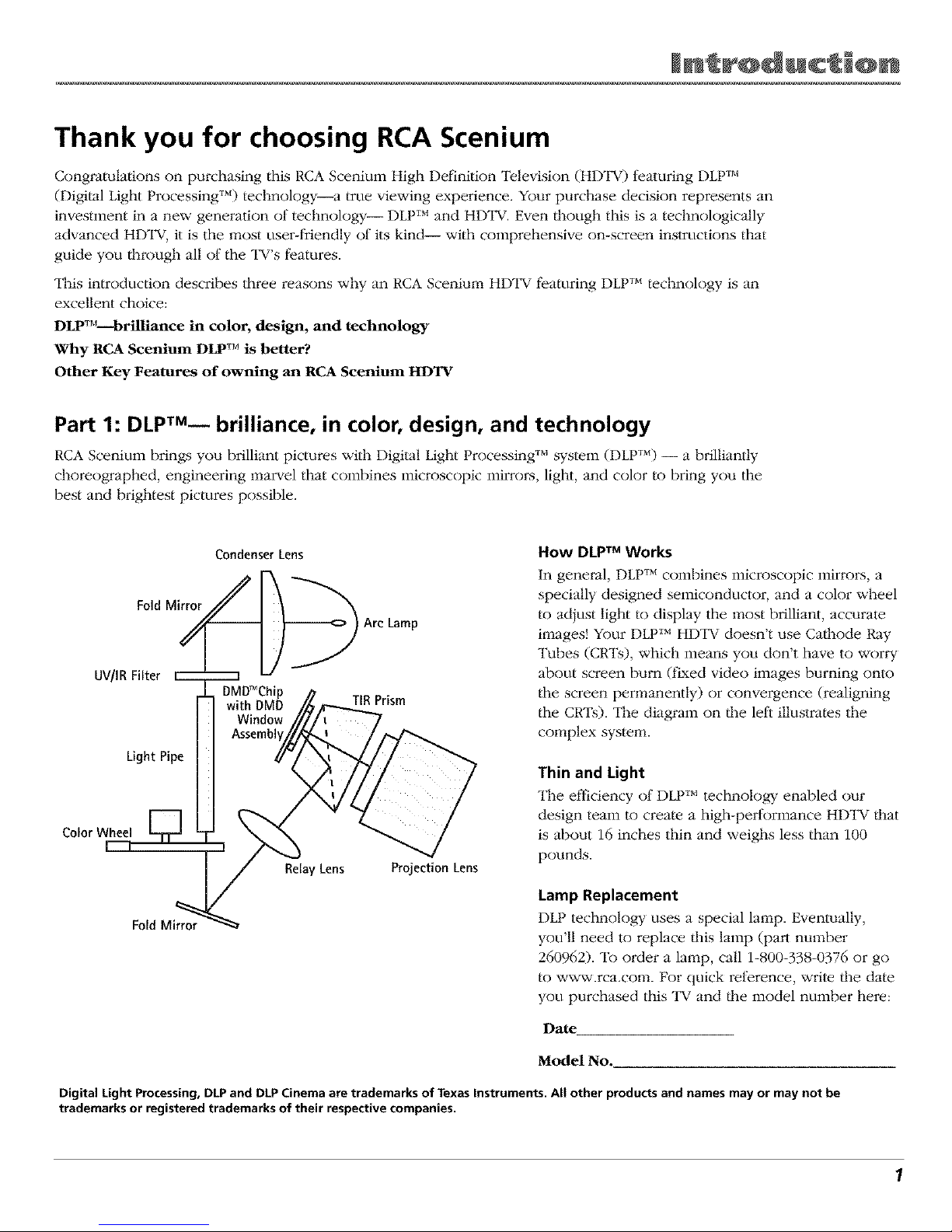
Fold Mirror
UV/IRFilter
Light Pipe
Color Wheel
Fold Mirror
Condenser Lens
Relay Lens
Arc Lamp
TIRPrism
Projection Lens
How DLPTM Works
In genei_al, I-)LPTM colnbines inicroscopic inirrons, a
specially designed semiconductor, and a color wheel
to adjust light to display the most brilliant, accurate
images! Your DLPTM HDTV doesn't use Ca/hode Ray
Tubes (CRTs), which means you don't have to worry
about screen burn (fixed video images burning onto
the screen permanently) or convergence (realigning
the CRTs). The diagram on/he lefi illustrates the
complex system.
Thin and Light
The efficiency of DLPTM technology enabled our
design team to create a high-performance HDl_V/hat
is about 16 inches thin and weighs less than 100
pounds.
Lamp Replacement
DLP technology uses a special lamp. Eventually,
you'll need m replace/his lamp (part number
260962). To order a lamp, call 1-800-338-0376 or go
to www.rca.com. For quick relZerence, write/he date
you purchased this TV and/he model number here:
Date
Model No.
Digital Light Processing, DLP and DLP Cinema are trademarks of Texas Instruments. All other products and names may or may not be
trademarks or registered trademarks of their respective companies.
1
Page 4
Part 2: Why RCA Scenium DLPTM is better?
DLPTM is just part of the story. You have chosen to embark on |he next generation of TV viewing-- Hr)TV. There are many
technological advancements that make HDTV better |han analog TV, but them are basically three things about HDTV that
bring you a superior viewing experience: (1) resolution, (2) aspect ratio, and (3) digital signal and sound.
Resolution (it's math...that works for you)
The crisp, lil_elike picture people rave about when experiencing true HDTV is due to the resolution this technology
provides. The resolution is measured by calculating the number of active lines of pixels. A pLxel (which stands tk)r picture
element) is a small dot. The picture you see on your "IV is composed of these dots.
A regular, analog television (called analog) only has a resolution of about 200,000 pb_els (480 vertical pLxels x 440 horizontal
pixels = 211,200 pLxels). The HDTV fbrmat is capable of morn than 2 million pLxels (1,920 x 1,080 = 2,073,600).
Morn pixels equals morn detail. In summary, HDTV is capable of resolution that is up to 10 times the resolution of/lie
picture on a regular, analog TV!
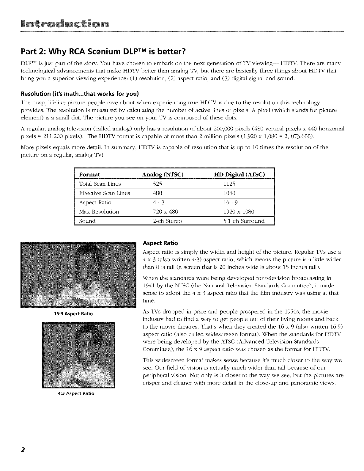
Format Analog (NTSC) HD Digital (ATSC)
Total Scan Lines 525 1125
Efli_ctive Scan Lines 480 1080
Aspect Ratio 4 : 3 16 : 9
Max Resolution 720 x 480 1920 x 1080
Sound 2-ch Stereo 5.1 ch Surround
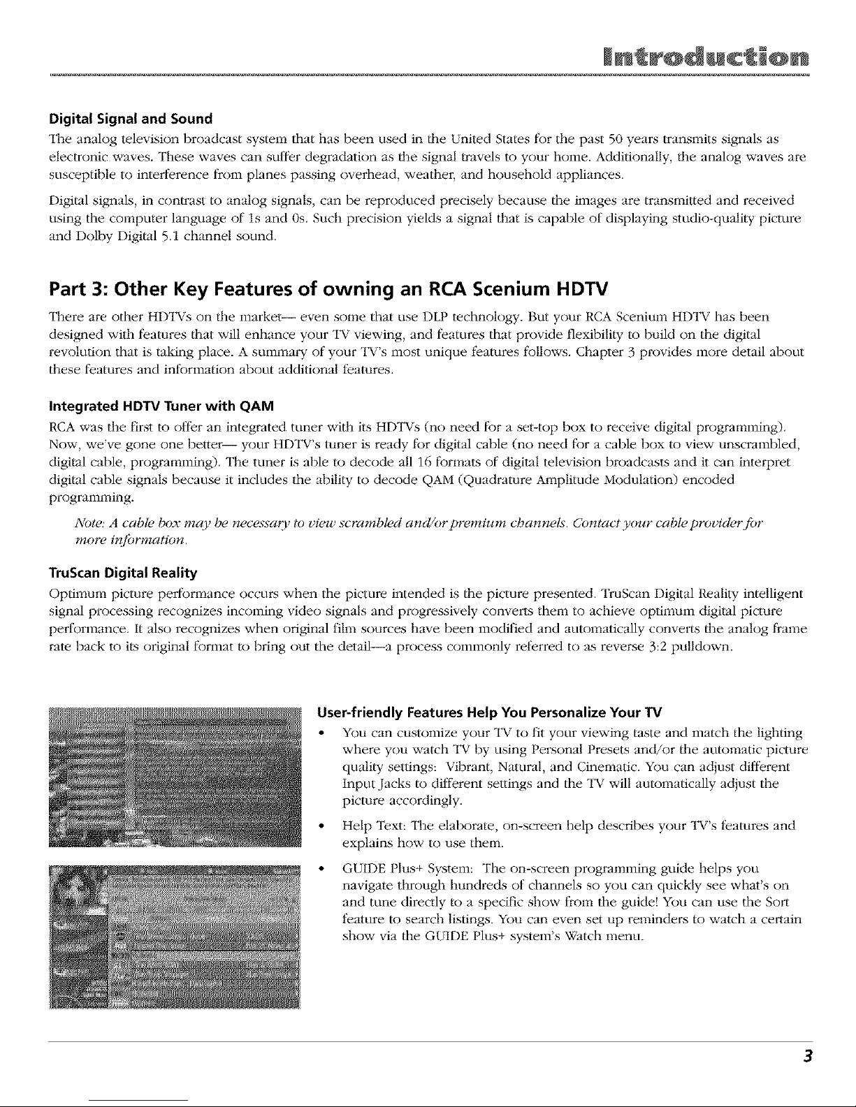
16:9 Aspect Ratio
4:3 Aspect Ratio
Aspect Ratio
Aspect ratio is simply the width and height of the picture. Regular "INs use a
4 x 3 (also written 4:3) aspect ratio, which means the picture is a little wider
than it is tall (a screen that is 20 inches wide is about 15 inches tall).
When/l_e standards were being developed fbr television broadcasting in
1941 by the NTSC (the National Television Standards Committee), it made
sense to adopt the 4 x 3 aspect ratio that/he film industry was using at that
time.
As TVs dropped in price and people prospered in/he 1950s, the movie
industry had to find a way to get people out of their living rooms and back
to the movie theatres. That's when they created/lie 16 x 9 (also written 16:9)
aspect ratio (also called widescreeen format). When the standards tbr HDTV
were being developed by the ATSC (Advanced "Pelevision Standards
Committee), the 16 x 9 aspect ratio was chosen as the tbrmat for HDTV.
This widescreen tbrmat makes sense because it's much closer to/l_e way we
see. Our field of vision is actually much wider/hart tall because of our
peripheral vision. Not only is it closer to the way we see, but the pictures are
crisper and cleaner with more detail in/he close-up and panoramic views.
2
Page 5
Digital Signal and Sound
The analog television broadcast system that has been used in the United States fbr the past 50 years transmits signals as
electronic waves. These waves can suffer degradation as/he signal _avels to your home. Additionally, /he analog waves are
susceptible to interl_rence from planes passing overhead, weather, and household appliances.
Digital signals, in con_ast to analog signals, can be reproduced precisely because/he images are transmit/ed and received
using the computer language of ls and 0s. Such precision yields a signal that is capable of displaying studio-quality picture
and Dolby Digital 5.1 channel sound.
Part 3: Other Key Features of owning an RCA Scenium HDTV
There are other HDTVs on the market-- even some that use DLP technology. But your RCA Scenium HDTV has been
designed with features that will enhance your "IV viewing, and fbatures that provide flexibili/y to build on the digital
revolution that is taking place. A summary of your TV's most unique features fbllows. Chapter 3 provides more detail about
these f_atums and inl_Jrmation about additional t_atums.
Integrated HDTV Tuner with QAM
RCA was the first to offer an integrated tuner with its HDTVs (no need fbr a set-top box to receive digital programming).
Now, we've gone one better-- your HDTV's tuner is ready fbr digital cable (no need fbr a cable box to view unscrambled,
digital cable, programming). The tuner is able to decode all 16 fbrmats of digital television broadcasts and it can interpret
digital cable signals because it includes the ability to decode QAM (Quadrature Amplitude Modulation) encoded
programming.
Note: A cable box map be necessao_ to view scrambled and/orpremium channels. Contact your cable provider for
more i*zfi_rmation.
TruScan Digital Reality
Optimum picture performance occurs when the picture intended is/he picture presented. TruScan Digital Reality intelligent
signal processing recognizes incoming video signals and progressively converts them to achieve optimum digital picture
performance. It also recognizes when original film sources have been modified and automatically conve_ls/he analog frame
rate back to its original fbrmat to bring out the detail_a process commonly rel;erred to as revense 3:2 pulldown.
User-friendly Features Help You Personalize Your TV
• You can customize your TV to fit your viewing taste and match the lighting
where you watch "IV by using Personal Presets and/or/he automatic picture
quality settings: Vibrant, Natural, and Cinematic. You can adjust different
Input Jacks to different settings and the "IV will automatically adjust the
picture accordingly.
• Help Text: The elaborate, on-screen help describes your TV's t)atures and
explains how to use them.
GUIDE Plus+ System: The on-screen programming guide helps you
navigate through hundreds of channels so you can quickly see what's on
and tune directly to a specific show from the guide! You can use the So_1
t;eature to search listings. You can even set up remindens to watch a certain
show via the GUIDE Plus+ system's Watch menu.
3
Page 6
FireWire® with Two-Way DTVLink®
Control your 1EEE-1394 components via your HDTV! Just link them toge/her via the 2-way DTVLink jacks and you can
network your high-speed compatible 1394 digital components. The two-way jacks allow/he audio and video signals to flow
into and out from the 1394 components, such as the DVR10 (see below).
Compatible with the Optional DVR10 Hard Disk Drive -- Pause Live Digital TV and record digital programs
RCA oilers an Audio Video Hard Disk Drive (model DVR10) with IEEE 1394, available at your local RCA dealer or
www.rca.com. The DVR10 Audio Video Hard Disk Drive (AVHDD) component lets you pause live TV, record shows, and
play/hem back without adding another box to your entertainment system (it records digital, ATSC broadcasts only). For
purchasing details, go to your local consmner electronics retailer or www.rca.com.
NetConnect
With an Ethernet connection and a web browser built into your "IV, you can
access the Internet from your TV*. To use the web browsei; you'll need a high-
speed connection, such as a DSL (Digital Subscriber Line) unit or cable modem
and a subscription to an 1SP (Internet Selwice Provider). DSL, cable modem, and
ISP subscription sold separately.
*The browser has limitations and might not be able to interpret all files, such as
TOget the most out of your HDTV'sweb
browser,purchasethe keyboard(model streaining at.tdio and video.
KBRg55TA1)designed specificallyfor your TV
(go to page 84for ordering information).
Audio System
Enioy the great sound system in your HDTV with 30 watts total powen Yottr HDTV has front speakers with two 1" tweetens
and two 5" midrange drivers to create incredible sound. A 7-band on-screen graphic equalizer allows customization of the
sound quality. SRS "lYuSurround XT provides surround sound technology and with two rear speaker outputs, enjoy/he
feeling of full surround sound. For those who w'ant to hook up a home theatre audio system, there is an optical Dolby
Digital output as well as a 50-watt center channel input.
Record Output Jacks
Because the VCRs in most households are analog and can't interpret digital signals, recording HDTV broadcasts wasn't
possible without purchasing additional equipment. That's why RCA added Record Output Jacks to/his HDTV -- the
RECORD OUTPUT with its AUDIO OUT L/R iacks enable you to record both analog and digital programs to an analog VCR.
RCA understands how you watch "IV and what is necessary to make/he transition to HDTV seamless.
CinemaScreen TM
Check out the black, borderless flame around your HDTV's screen. This is not just a design t_eature- the CinemaScreen
actually enhances contrast. Feel like you're part of the picture with CinemaScreen.
What's Next?
If you didn't have your HDl_V prol;essionally installed, go to Chapter 1 fbr instructions. The rest of this User's Guide explains
the f)atures in more detail, the remote control, and the menu system.
Note: For U.S. customers: If you prefer, we can provide you with the name (g_an Authorized Service Representative
who will visit your home fi_r afee to install your electronics entertainment system and to inst_wct you in its operation.
For details about this service, call 1-888-206-33 59.
DTVLink®CertificationLogo isa U.S.registeredmarkof CEA.
FireWireisa trademarkof AppleComputer,Inc., registeredin the U.S.and other countries.
4
Page 7
TalblM @f Con't n'ts
Introduction
Key Features Overview ................................................................................................................... 1
Chapter 1: Connections & Setup
Things to Consider Before You Connect ........................................................................................ 8
Choose Your Connection ................................................................................................................. 9
How to Connect: TV + VCR + DVD Player ............................................................................. 10
How to Connect: TV + Satellite Receiver + VCR .................................................................... 11
How to Connect: TV + Receiver with Dolby Digital + Speakers ........................................... 12
How to Connect: TV + A/V/Receiver + Speakers + Use TV as Center Channel .................... 12
How to Connect: TV + Speakers Without A/V Receiver ....................................................... 14
How to Connect: TV + Router via the HDTV's ETHERNET Jack ............................................ 15
How to Connect: TV + DTVLink® and/or 1394 Components ............................................... 16
How to Connect: TV + Set-top Box Using DVI-HDTV (Digital Visual interface) .................. 17
Explanation of Input Jacks and Cables ........................................................................................ 18
Back of the TV ................................................................................................................................ 20
Why You Should Connect the G-LINK Cable ................................................................................ 23
How to Find the Remote Sensor ............................................................................................ 23
Placing the G-LINK Wands ..................................................................................................... 23
The Front of Your TV ..................................................................................................................... 24
Button Lighting (available on some models) ........................................................................ 24
Front Input Jacks ..................................................................................................................... 24
Front Panel .............................................................................................................................. 24
Plug in the TV ................................................................................................................................. 25
Put batteries in the remote ........................................................................................................... 25
Turn on the TV ............................................................................................................................... 25
Use the Remote Control to Complete the Assisted Setup .......................................................... 25
Complete the Assisted Setup ........................................................................................................ 26
Set the Menu Language ......................................................................................................... 26
Complete Channel Search ...................................................................................................... 26
The GUIDE Plus+ System Setup .............................................................................................. 26
What to Expect .............................................................................................................................. 30
Next Steps ...................................................................................................................................... 30
Chapter 2: Using the Remote Control
The Buttons on the Remote Control ............................................................................................ 32
Programming the Remote to Operate Other Components ........................................................ 34
Now to Use the Remote After You've Programmed It ............................................................... 35
The Learning Feature .................................................................................................................... 36
Volume Punchthrough Feature ..................................................................................................... 38
Using the Input Button ................................................................................................................. 39
Remote Code List ........................................................................................................................... 39
Chapter 3: Using the TV's Features
About the Channel Banner ........................................................................................................... 42
Digital or Analog TV Channels ..................................................................................................... 43
About the GUIDE Plus+ System .................................................................................................... 44
Parental Controls ........................................................................................................................... 48
How V-Chip Works for the USA and Canada ............................................................................... 49
Auto Tuning Feature ...................................................................................................................... 55
PIP (Picture-in-Picture) Operation ................................................................................................. 56
Using the Web Browser ................................................................................................................ 58
1394 Recording .............................................................................................................................. 59
Page 8
TalblM @f Con't n'ts
Chapter 4: Using the TV's Menu System
Menus, On-screen Help, and Control Panels ...............................................................................
Picture Quality Menu ....................................................................................................................
Picture Settings .......................................................................................................................
Picture Presets .........................................................................................................................
Auto Color ...............................................................................................................................
Color Warmth .........................................................................................................................
Noise Reduction ......................................................................................................................
Advanced Settings ..................................................................................................................
Reset Controls .........................................................................................................................
Audio Menu ...................................................................................................................................
Equalizer Presets .....................................................................................................................
Audio Processor ......................................................................................................................
Sound Logic .............................................................................................................................
Audio Language .....................................................................................................................
SAP (Second Audio Program) .................................................................................................
Balance ....................................................................................................................................
Fixed/Variable Out ..................................................................................................................
Digital Audio Out ...................................................................................................................
62
64
64
64
65
65
65
65
56
66
67
67
68
68
68
68
69
69
Time Menu ..................................................................................................................................... 70
Connections Menu ......................................................................................................................... 70
Antenna lnfo ........................................................................................................................... 70
Channel Search ....................................................................................................................... 71
Software Upgrade .................................................................................................................. 71
Signal Source ........................................................................................................................... 71
Signal Type .............................................................................................................................. 71
Auto Tuning ............................................................................................................................ 72
1394 Setup .............................................................................................................................. 72
Special Features ...................................................................................................................... 72
Ethernet Setup ........................................................................................................................ 72
Preferences Menu .......................................................................................................................... 73
Closed Captioning .................................................................................................................. 73
Screen Format ......................................................................................................................... 74
Record Output ........................................................................................................................ 75
Color Scheme .......................................................................................................................... 75
Translucency ............................................................................................................................ 76
Menu Language ...................................................................................................................... 76
Button Lighting ...................................................................................................................... 76
Digital Channel lnfo ............................................................................................................... 76
Lamp Power ............................................................................................................................ 76
Chapter 5: Reference
Troubleshooting ............................................................................................................................. 78
HDTV Specifications ...................................................................................................................... 82
Accessory Information .................................................................................................................. 84
Limited Warranty ........................................................................................................................... 87
Care and Cleaning ......................................................................................................................... 88
FCCInformation ............................................................................................................................. 89
Index ............................................................................................................................................... 90
6
Page 9
Chapter
0 • •
Things to Consider Before You Connect
• Choose Your Connection
• Why You Should Connect the G-LINK Cable
• The Front of Your TV
• Put Batteries ir the Remote
• Turn on the
• Use theRemote Control to Complete
the Assisted_ Setup
• Complete the Assisted Setup
• What to Expect
• Next Steps
J
Graphics c( ntained within this publication are fi)r representati( n on{}.
7
Page 10
CQnn c' @ns S ' up
Things to Consider Before You Connect
Protect Against Power Surges
• Connect all components before you plug any of their power cords into/he wall outlet or power strip. NEVER plug
your "I_Vinto an ou/let that is con_rolled by a wall switch.
• Turn off the TV and/or component(s) before yon connect or disconnect any cables.
• Make sure all antennas and cables are properly grounded. Refer to the Important Safi_guards sheet packed with
your "FV.
Protect Components from Overheating
• Don't block ventilation holes on any of/he components. Arrange the components st) that air can circulate freely.
• Don't stack components.
• If yon place components in a stand, make sure yon allow adequate ventilation.
• If yon connect an audio receiver or amplifier, place it on the top shelf so the heated air Dora it won't flow around
other components.
Position Cables Properly to Avoid Audio Interference
• Insert each cable firmly into the designated jack.
Use Indirect Light
Don't place the TV where sunlight or room lighting will be directed toward the screen. Use soli or indirect lighting.
Using a Stand
This television is a table model and is designed to set on a firm, fiat surthce. Placing the TV on sott carpeting or a like
surface can block/he bottom ventilation slots and result in reduced lifetime due to overheating. Make sure the stand or
base you use is of adequate size and strength to prevent the "I_Vfrom being accidentally tipped over, pushed off, or
pulled off. This could cause personal iniulT and/or damage the "FV.Refer to the Important Satiety Instructions packed
separately.
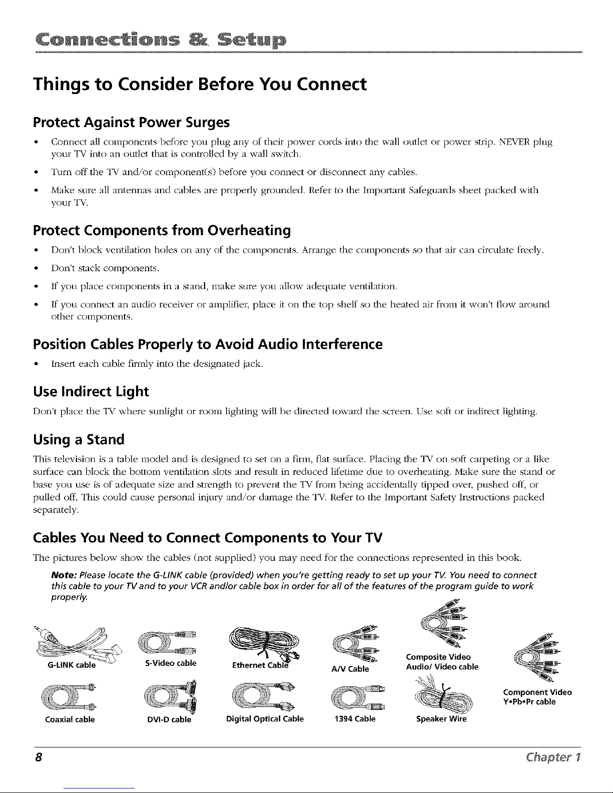
Cables You Need to Connect Components to Your TV
The pictures below show the cables (not supplied) you may need tbr the connections represented in this book.
Note: Pleaselocate the G-LINKcable (provided) when you're getting ready to set up your r_ You need to connect
this cable to your TVand to your VCRand/or cable box in order for all of the features of the program guide to work
properly.
S*Video cable
Coaxial cable DVI_D cable
A/V Cable
Digital Optical Cable 1394 Cable
Composite Video
Audio/Video cable
Speaker Wire
Component Video
Y,Pb,Pr cable
8 Chapter
Page 11
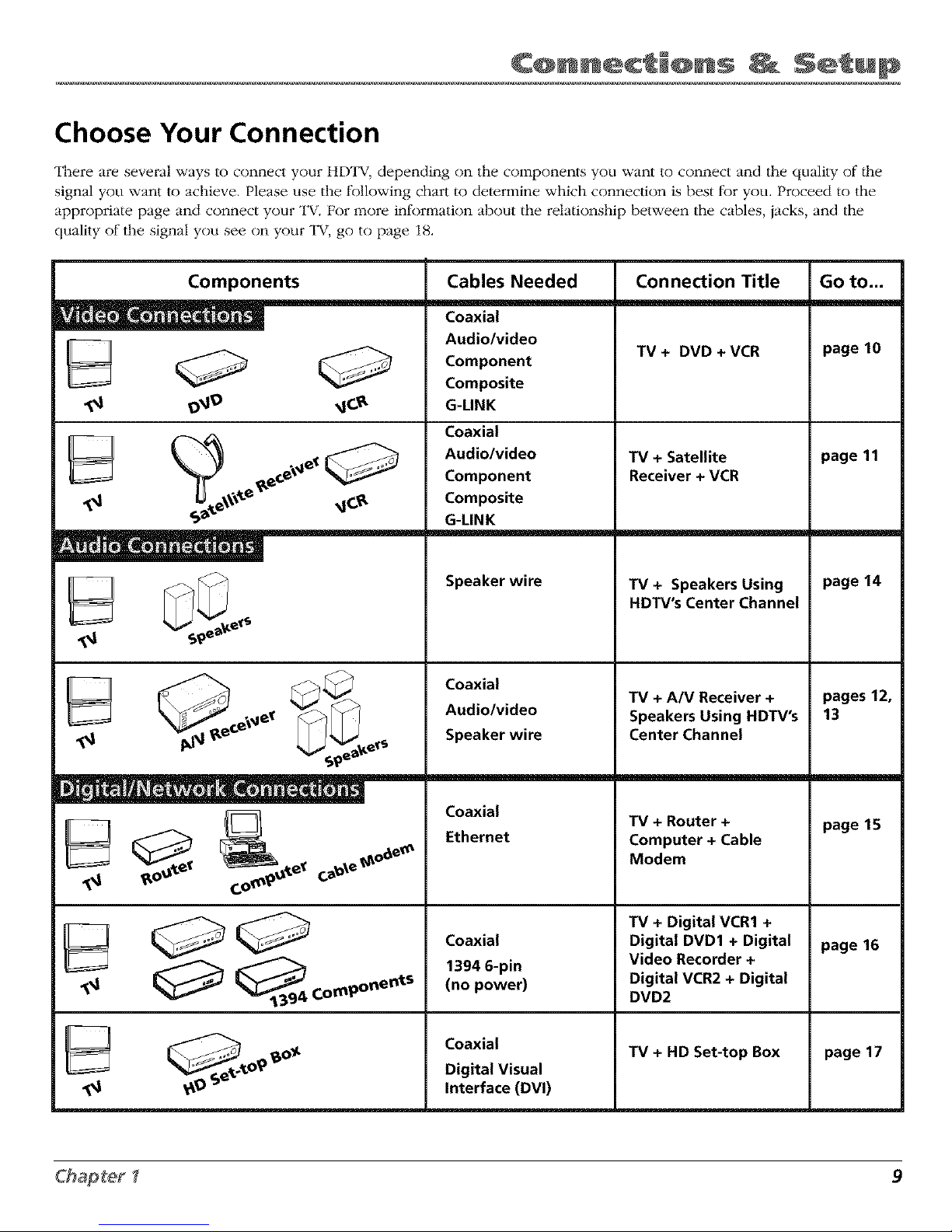
Choose Your Connection
There am several ways to connect your HDTV, depending on the components you want to connect and the quality of/he
signal you want to achieve. Please use the fk)llowing chart to determine which connection is best fkJryou. Proceed to the
appropriate page and connect your TV, For more inlk)rmation about the relationship between the cables, jacks, and the
quality of the signal you see on your "IV, go to page 18.
Components Cables Needed Connection Title Go to...
¢'e
Coaxial
Audio/video
Component
Composite
G-LINK
Coaxial
Audio/video
Component
Composite
G-LINK
Speaker wire
Coaxial
Audio/video
Speaker wire
Coaxial
Ethernet
Coaxial
1394 6-pin
(no power)
Coaxial
Digital Visual
Interface (DVI)
TV+ DVD+VCR
TV + Satellite
Receiver + VCR
TV + Speakers Using
HDTV's Center Channel
TV + A/V Receiver +
Speakers Using HDTV's
Center Channel
TV + Router +
Computer + Cable
Modem
TV + Digital VCR1 +
Digital DVD1 + Digital
Video Recorder +
Digital VCR2 + Digital
DVD2
TV + HD Set-top Box
page 10
page 11
page 14
pages 12,
13
page 15
page 16
page 17
9
Page 12
CQnn c' @ns S ' up
Note for U.S. Customers: If you
prefer, we can provide you with
the name of an Authorized
Service Representative who will
•_ visityourhome fora fee to install
your electronic entertainment
system and to instruct you in its
operation. For details about this
service, call 1-888-206-3359. For
additional assistance while using
_M v your RCA product, please visit
www.rcascenium.com/customer
s_.
• m
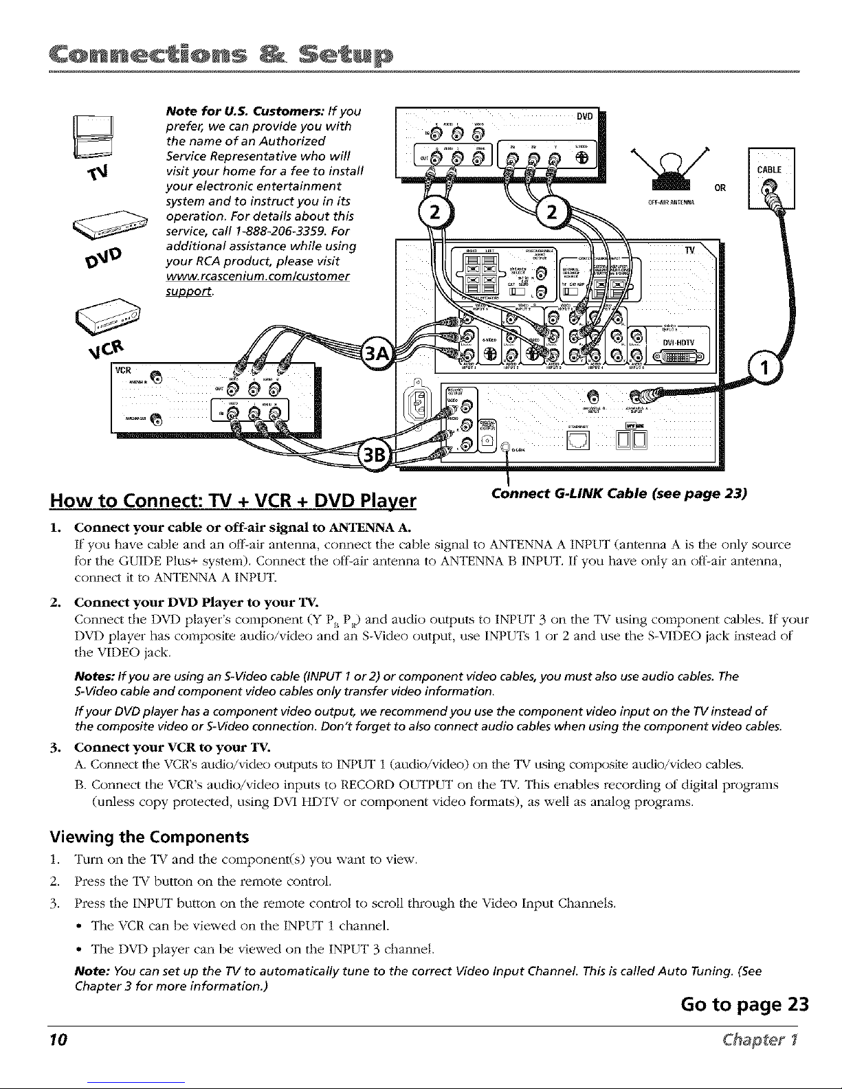
How to Connect: TV + VCR + DVD Player Connect G-LINK Cable (see page 23)
1. Connect your cable or off-air signal to AI_ENNA A.
If"you have cable and an off-air antenna, connect tile cable signal to AI"_FENNA A INPUT (antenna A is the only source
fkJr the GUIDE Plus+ system). Connect the olin-air antenna to ANTENNA B INPUT. If you have only an olt2air antenna,
connect it to ANTENNA A INPIFK
2o
°
Connect your DVD Player to your TV.
Connect the DVD player's component (Y P,, PR) and audio outputs to INPUT 3 on the •IV using component cables. If your
DVD player has composite audio/video and an S-Video output, use INPUTs 1 or 2 and use the S-VIDEO iack instead of
the VIDEO jack.
Notes: If you are using an S-Video cable (INPUT I or 2) or component video cables, you must also use audio cables. The
S-Video cable and component video cables only transfer video information.
If your DVD player has a component video output, we recommend you use the component video input on the TVinstead of
the composite video orS-Video connection. Don't forget to also connect audio cables when using the component video cables.
Connect your VCR to your _.
A. Coimect the VCR's audio/video outputs to INPUT 1 (audio/video) on the TV using composite audio/video cables.
B. Connect the VCR's audio/video inputs to RECORD OUTPUT on the l_V. This enables recording of digital programs
(unless copy protected, using DVI HDTV or component video fkJrlnats), as well as analog programs.
Viewing the Components
1. Turn on tile TV and the component(s) you want to view.
2. Press the TV button on the remote control.
)
3. Press the IN1 UT button on the remote control to scroll through the Video Input Channels.
)
• The VCR can be viewed on the INt UT 1 channel.
• The DVD player can be viewed on the INPUT 3 channel.
Note: You can set up the rg to automatically tune to the correct Video Input Channel. This is called Auto Tuning. (See
Chapter 3 for more information.)
Go to page 23
10 Chapter
Page 13
SATE[UTE
RECEIVER
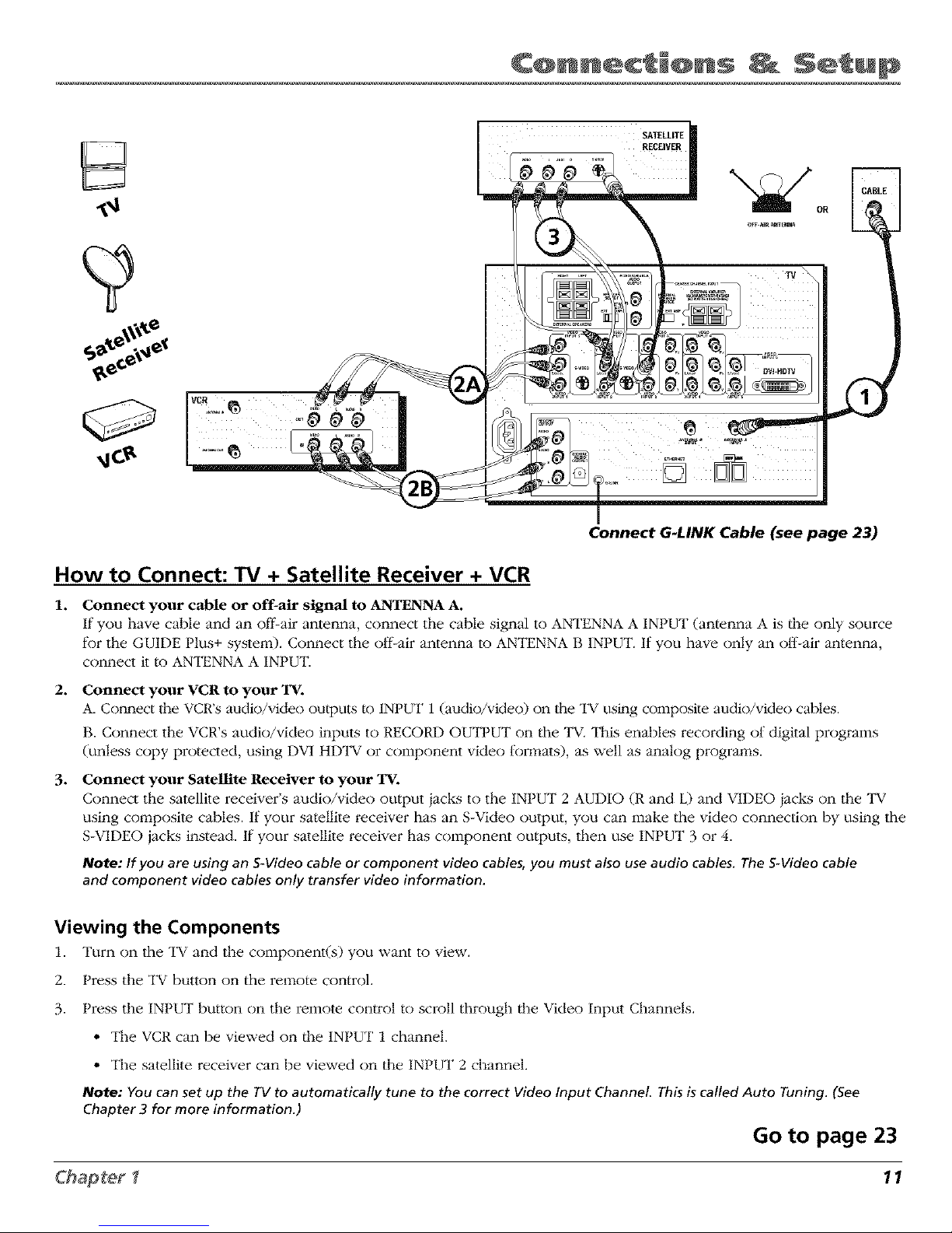
Connect G-LINK Cable (see page 23)
How to Connect: TV + Satellite Receiver + VCR
1. Connect your cable or off-air signal to ANTENNA A.
If you have cable and an off-air antenna, connect the cable signal to ANTENNA A INPUT (antenna A is |he only source
f_Jrthe GUIDE Plus+ system). Connect the ol_-air antenna to ANTENNA B INPUT. If you have only an ol]_air antenna,
connect it to ANTENNA A INPUT.
2. Connect your VCR to your TV.
A. Com_ect the VCR's audio/video ou/puts/o INPUT 1 (audio/video) on the "IV using composite audio/video cables.
B. Connect the VCR's audio/video inputs to RECORD OUTPUT on the l_V. This enables recording of digital programs
(unless copy protected, using DV1 HDTV or component video tk)rmats), as well as analog programs.
3. Connect your Satellite Receiver to your 'rv.
Connect the satellite receiver's audio/video output jacks to the INPUT 2 AUDIO (R and L) and VIDEO jacks on the TV
using composite cables. If your satellite receiver has an S-Video output, you can make the video connection by using the
S-VIDEO jacks instead. If your satellite receiver has component outputs, then use INPI.IT 3 or 4.
Note: If you are using an S-Video cable or component video cables, you must also use audio cables. The S-Video cable
and component video cables only transfer video information.
Viewing the Components
1. Turn on the TV and the coinponent(s) you want to view.
)
2. tress the TV button on the remote control.
) 3
3. tress the IN1 UT button on the remote con/rol to scroll through the Video Input Channels.
• The VCR can be viewed on the INPUT 1 channel.
• The satellite receiver can be viewed on the INPUT 2 channel.
Note: You canset up the rv to automatically tune to the correct Video Input Channel. This is called Auto Tuning. (See
Chapter 3 for more information.)
Go to page 23
11
Page 14
CQnn c' @ns S ' up
Audio Connections
With the audio versatility of your HDTV, you can choose various connection options depending on tile type and quality
of sound that you want. Choose one of the options or relier to the user's manual of each component that you are
connecting to get the best results.
• Connect audio/video receiver (speakers connected to receive0 using the digital audio outpu/ jack /o your TV (best sound).
• Connect audio/video receiver (speakers connected to receiver) to your "IV (better sound).
• Connect speake*:s to your TV (good sound).
How to Connect: TV + Receiver with Dolby Digital + Speakers
If you own a receiver with Dolby Digital® or PCM (Pulse-Code Modulation) audio receiver that uses an optical cable-wpe
input, connect an optical cable tk)r excellent audio quality (shown on opposite page).
1. Connect one end of the optical cable to the DIGITAL AUDIO OUT jack on your TV to the DIGITAL OPTICAL INPUT
Jack on your receiver/amplifier receiver.
2,
• If your receiver can decode Dolby Digital and PCM, go to Audio menu, select DigitalAudio Output, and
select AutoSelect (recommended) or PCM option.
• If your receiver can decode only PCM, go to Audio menu, select Digital Audio Output, and select PCM
option.
If you want to use your "IV as the Center Channel, use speaker wire to connect the audio receiver's CENTER
SPEAKER OUTPUT to the TV's CENTER CHANNEL INPUT as shown on the opposite page.
• Switch INTERNAL SPEAKER SOURCE to EXT AMR
3. Use speaker wire to connect the Audio/Video receiver to external front and rear speake_:s. Relier to your audio
receiver manual to complete speaker hookup to the receiver.
OR
How to Connect: TV + A/V Receiver + Speakers + Use TV as Center Channel
1. Connect the FIXE1-)/VARIABLEAUDIO OUTPUT from the l_V to an A/V receiver using audio cables.
2. Be sure to go to the Fixed/Variable Out screen in the Audio menu and select whether you want the FIXED/
VARIABLEAUDIO OUTPUT jacks to send fLxed volume audio or variable volume audio.
• Fixed Output provides fLxed-level audio output from the TV. This audio output is ideal tkJr connecting to an
A/V receiver that has its own volume control.
• Va_qable Output provides variable-level audio output. Volume levels are con_olled by the volume controls on
the TV and TV remote control.
3. If you want to use your "IV as the Center Channel, use speaker wire to connect the audio receiver's CENTER
SPEAKER OUTPUT to the TV's CENTER CHANNEL INPUT as shown on the opposite page.
• Switch INTERNAL SPEAKER SOURCE to EXT AMP.
4. Use speaker wire to connect the Audio/Video receiver to external front and rear speake_:s. Relier to your audio
receiver manual to complete speaker hookup to the receiver.
Notes: Theexternal speaker rating is 8 ohms with 30 watts total power handling capabilities.
*Manufactured under license from Dolby Laboratories. "Dolby" and the double-D symbol are trademarks of Dolby Laboratories.
12 Chapter I
Page 15
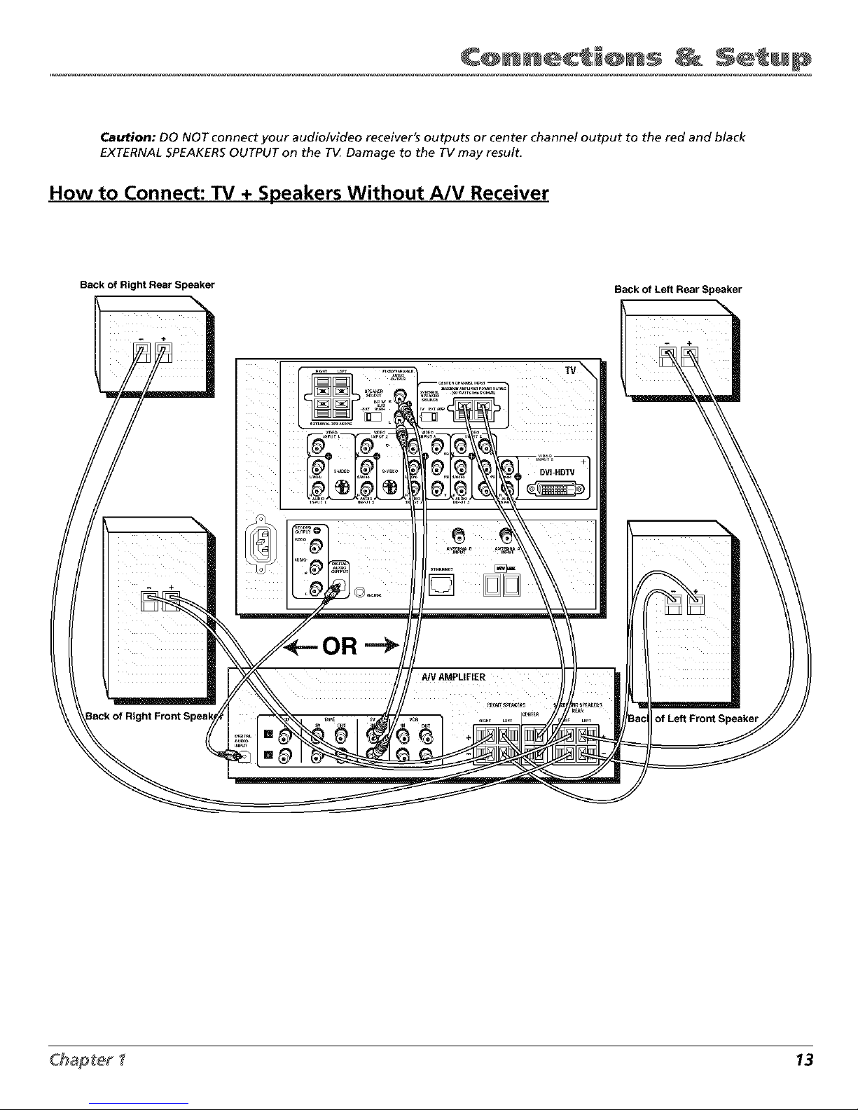
Caution: DO NOT connect your audio/video receiver's outputs or center channel output to the red and black
EXTERNAL SPEAKERSOUTPUT on the TV Damage to the TV may result.
How to Connect: TV + Speakers Without A/V Receiver
Back of Right Rear Speaker Back of Left Rear Speaker
-
- +
+
AN AMPLIFIER
of Left Front
13
Page 16
CQnn c' @ns S ' up
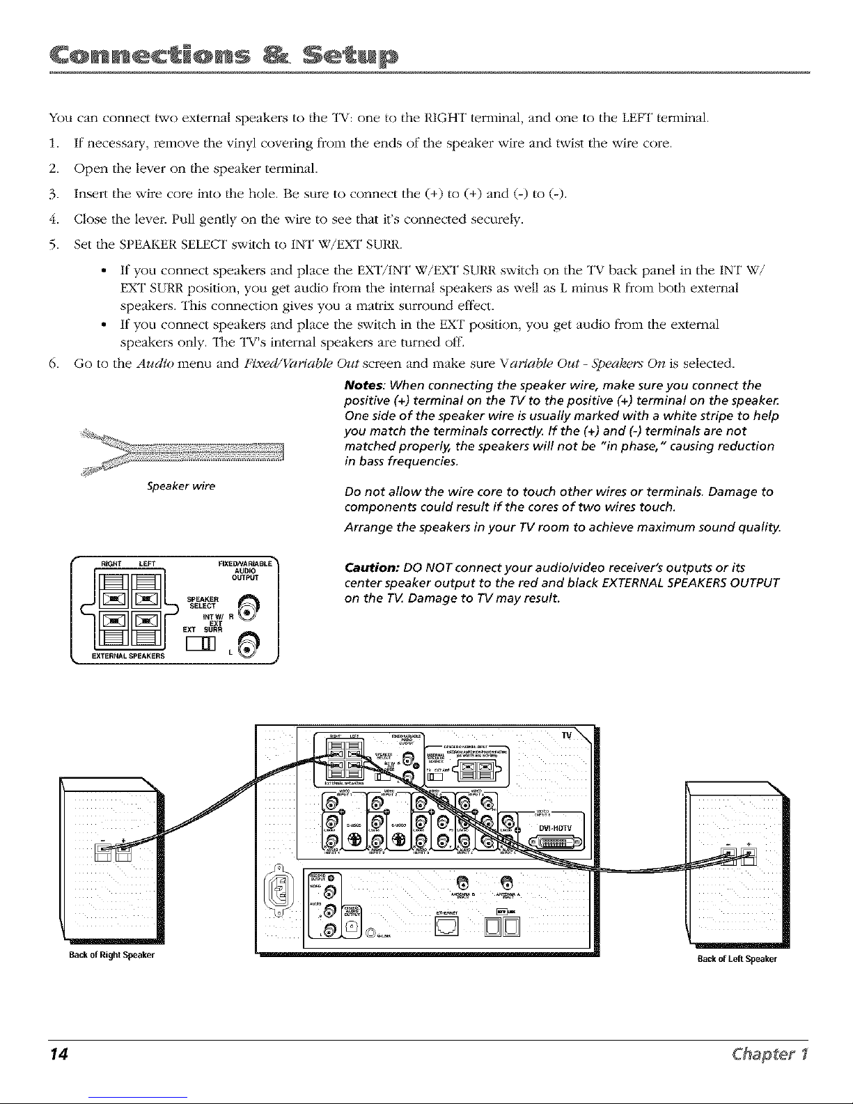
You can connect two external speakers to |he TV: one to the RIGHT terminal, and one to the LEFT terminal.
1. If necessary, remove the vinyl covering from the ends of the speaker wire and twist the wire core.
2. Open the lever on the speaker terminal.
3. Insert the wire core into the hole. Be sure to connect the (+) to (+) and (-) to (-).
4. Close the levei_ Pull gently on _he wire to see that it's connected securely.
5. Set the SPEAKER SELECT switch to 1NT W/EXT SURR.
• If you connect speakers and place the EXT/1NT W/EXT SURR switch on the TV back panel in the INT W/
EXT SURR position, you get audio from tile internal speakers as well as L minus R from both external
speakei_s. This connection gives you a ma/rL,_ surround eltk:ct.
• If you connect speakers and place the switch in the EXT position, you get audio from the external
speakei_s only. The TV's internal speakers are turned off.
6. Go to the Audio menu and Fixed/Variable Out screen and make sure Variable Out - Spealaers On is selected.
Notes: When connecting the speaker wire, make sure you connect the
positive (+) terminal on the TV to the positive (+) terminal on the speake_
One side of the speaker wire is usually marked with a white stripe to help
you match the terminals correctly. If the (+) and (-) terminals are not
matched properly, the speakers will not be "in phase," causing reduction
in bass frequencies.
Speaker wire Do not allow the wire core to touch other wires or terminals. Damage to
components could result if the cores of two wires touch.
Arrange the speakers in your TV room to achieve maximum sound quality.
RIGHT LEFT FIXED,_/A RIABLE _
AUDI_
OUTPUT
SPEAKER
SELECT
tNTW/ R
EXT
EXT _I/RR
EXTERNAL SPEAKERS L
Caution: DO NOT connect your audio/video receiver's outputs or its
center speaker output to the red and black EXTERNAL SPEAKERS OUTPUT
on the T_ Damage to TVmay result.
Back of RightSpeaker
[]
Back of LeRSpeaker
14 Chapter
Page 17
Router
Cable Modem/DSL Internet
TV
Computer
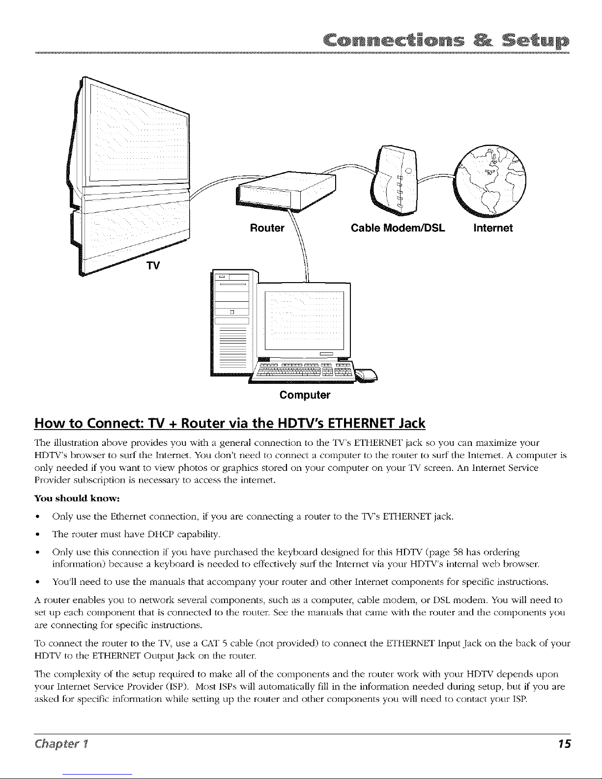
How to Connect: TV + Router via the HDTV's ETHERNET Jack
The illustration above provides you with a general connection to the TV's ETHERNET jack so you can maximize your
HDTV's browser to surf the Internet. You don't need to connect a computer to the router to surf the Intemet. A computer is
only needed if you want to view photos or graphics stored on your computer on your l_V screen. An Internet Selwice
Provider subscription is necessary to access the intemet.
You should know:
• Only use the Ethernet connection, if"you are connecting a router to the TV's ETHERNET jack.
• The router must have DHCP capabili)y.
• Only use this connection if you have purchased/he keyboard designed lk)r this HDTV (page 58 has ordering
infbrmation) because a keyboard is needed to el_k_ctively surf"the Internet via your HDTV's internal web browser.
• You'll need to use the manuals that accompany your router and other lnternet components fi)r specific ins)ructions.
A router enables you to network several components, such as a compute_; cable modem, or DSL modem. You will need to
set up each component that is connected to the router. See/lie manuals flint came with/lie router and/lie components you
are connecting lk)r specific instructions.
To connect the router to the "IV, use a CAT 5 cable (not provided) to connect the ETHERNET Input Jack on the back of your
HDTV to the ETHERNET Output Jack on/lie router.
The complexi)y of the setup required to make all of the components and the router work wi/h your HDTV depends upon
your Internet Service Provider (ISP). Most ISPs will automatically fill in the inlk)rmation needed during setup, but if you are
asked for specific information while setting up/lie router and other components you will need to contact your ISP.
15
Page 18
CQnn c' @ns S ' up
TV
Digital Video Recorder Digital VCR
_ Digital VCR
_l Other 1394 Component
Hub Connection
Fastest_ f_ Siowest
°°°''
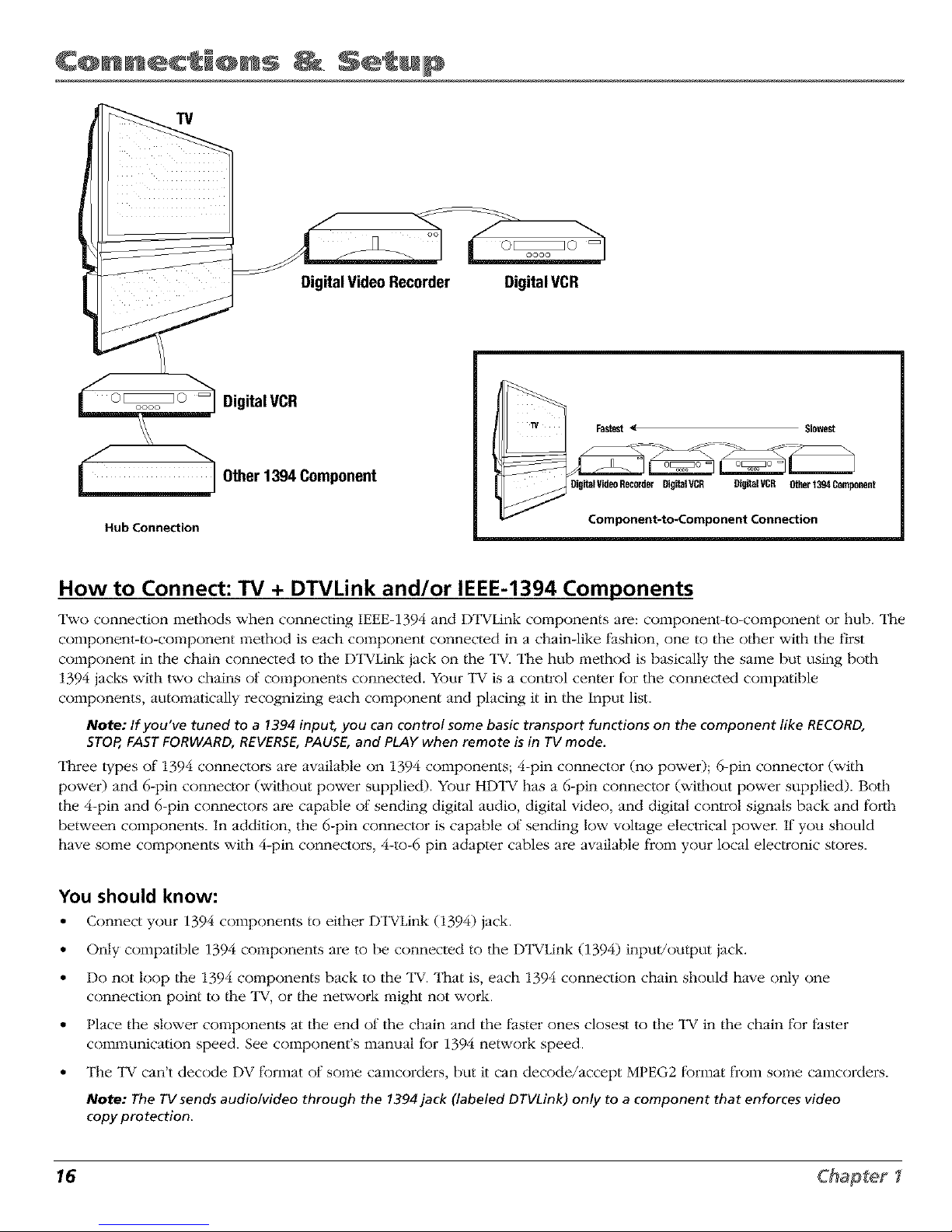
How to Connect: TV + DTVLink and/or IEEE-1394 Components
Two connection methods when connecting IEEE-1394 and DTVLink components are: component-to-component or hub. The
component-to-component method is each component connected in a chain-like fashion, one to the o/her with the first
component in the chain connected to the Dl_VLink jack on the "IV. The hub method is basically the same but using both
1394 jacks with two chains of components connected. Your TV is a con_ol center t_)r the connected compatible
components, automatically recognizing each component and placing it in the Input list.
Note: If you've tuned to a 1394input, you can control some basic transport functions on the component like RECORD,
STOP,FASTFORWARD,REVERSE,PAUSE,and PLAYwhen remote is in TVmode.
Three types of 1394 connector,s are available on 1394 components; 4-pin connector (no power); 6-pin connector (with
power) and 6-pin connector (without power supplied). Your HDTV has a 6-pin connector (wi/hout power supplied). Both
the 4-pin and 6-pin connectors are capable of sending digital audio, digital video, and digital control signals back and tbrth
between components. In addition, the 6-pin connector is capable of sending low voltage electrical powei: If you should
have some components with 4-pin connectors, 4-to-6 pin adapter cables are available from your local elec_onic stores.
You should know:
• Connect your 1394 components to either DTVLink (1394) jack.
• Only compatible 1394 components are to be connected to the DTVLink (1394) inpu//output jack.
• Do not loop the 1394 components back to the "IV. That is, each 1394 connection chain should have only one
connection point to/he TV, or/he network might not work.
• Place the slower components at the end of the chain and the faster ones closest to the TV in the chain t_Jr thster
communication speed. See component's manual tkJr1394 network speed.
• The TV can't decode DV t_Jrmat of some camcorders, but it can decode/accept MPEG2 t_Jrmat from some camcorders.
Note: The TVsends audiolvideo through the 1394jack (labeled DTVLink) only to a component that enforces video
copy protection.
16 Chapter
Page 19
HD Set Top Box
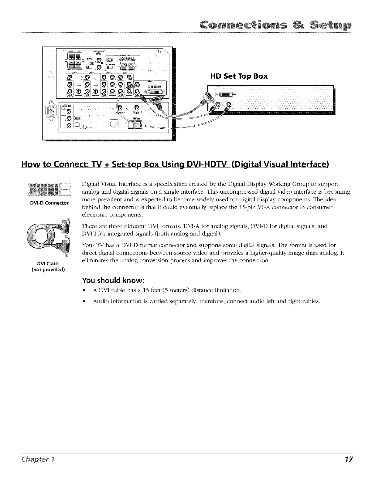
How to Connect: TV + Set-top Box Using DVI-HDTV (Digital Visual Interface)
DVI-D Connector
DVI Cable
(not provided)
Digital Visual Interfbce is a specification created hy/he Digital Display Working Group to support
analog and digital signals on a single interlace. This uncompressed digital vide() interface is hecoming
more prevalent and is expected to hecome widely used l_)r digital display components. The idea
hehind the connector is that it could eventually replace the 15-pin VGA connector in c(msumer
electronic components.
There are three dilI)rent DVI formats: DV1-A tk)r analog signals, DV1-D tk)r digital signals, and
DVI-I fbr integrated signals (both analog and digital).
Your TV has a DV1-D tk)rmat connector and supports some digital signals. "ll_e fbmlat is used for
direct digital connections between source video and provides a higher-quality image than analog. It
eliminates the analog conversion process and improves the connection.
You should know:
• A DVI cable has a 15 t_et (5 meters) distance limitation.
• Audio inlkm_ation is carried separately; therefore, connect audio leli and right cables.
17
Page 20
CQnn c' @ns S ' up
Explanation of Input Jacks and Cables
This section describes the jacks and cables you might use to make connections (cables may be ordered separately by using
the order form on page 85). There are several ways to connect components to your TV.
Difl_rent jacks and cables provide a different level of perfkmnance. It's important to remember the different degrees of
picture improvement for comparison. The component jacks are considered an excellent improvement; S-Video and
composite jacks are considered very good, while connecting components with the antenna RF connection is good.
I vm_
INPUT5
DVI-HDTV
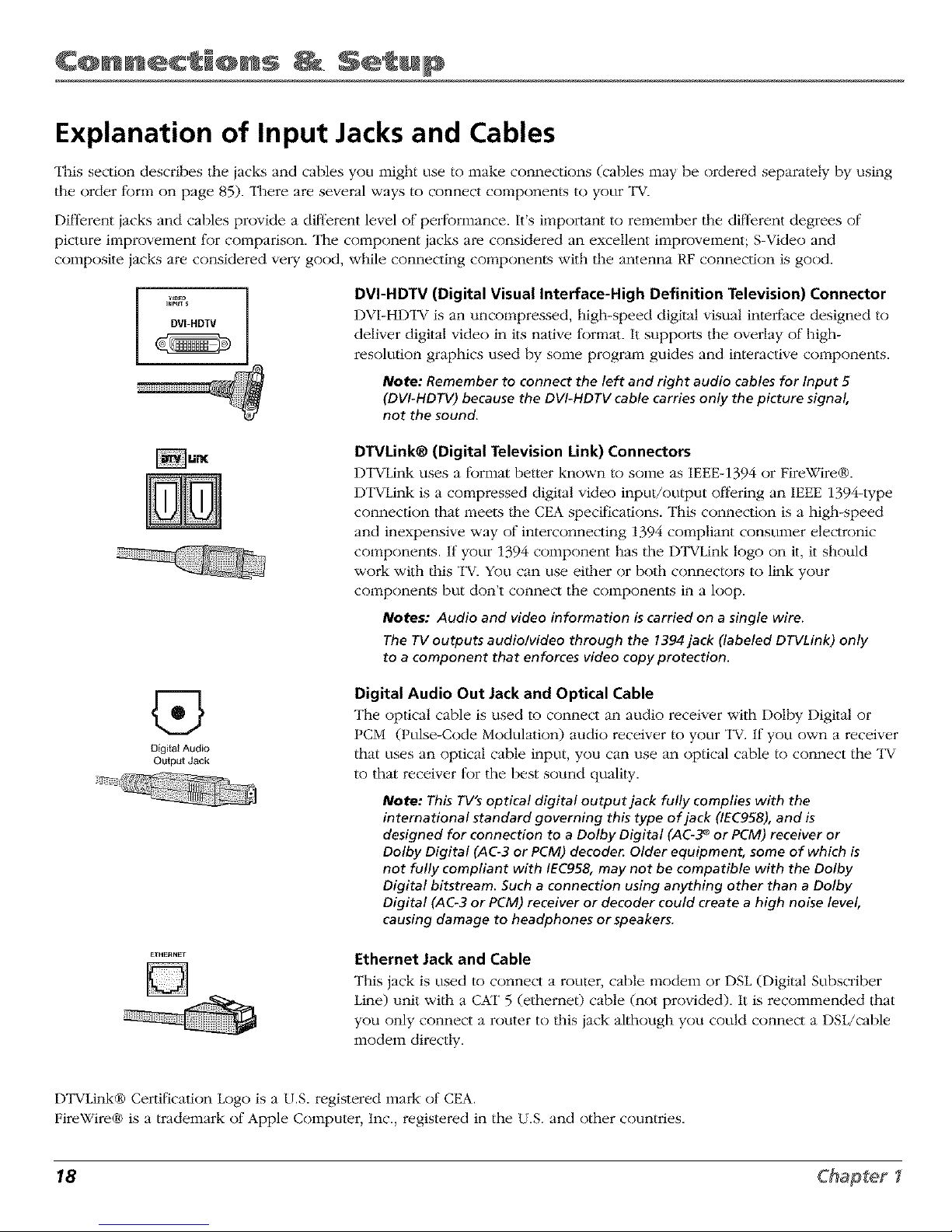
DVI-HDTV (Digital Visual Interface-High Definition Television) Connector
DVI-HDTV is an uncompmssed, high-speed digital visual interface designed to
deliver digital video in its native tk)rmat. It suppo_ls the overlay of high-
resolution graphics used by some program guides and interactive components.
Note: Remember to connect the left and right audio cables for Input 5
(DVI-HDTV)because the DVI-HDTV cable carries only the picture signal,
not the sound.
DTVLink® (Digital Television Link) Connectors
1-)TVLink uses a fbrmat better known to some as IEEE-1394 or FireWire®.
DTVLink is a compressed digital video input/output ofl:ering an IEEE 1394-type
connection that meets/lie CEA specifications. This connection is a high-speed
and inexpensive way of interconnecting 1394 compliant consumer electronic
components. If your 1394 component has the DTVLink logo on it, it should
work with/llis "IV. You can use eidmr or both connectors to link your
components but don't connect the components in a loop.
Notes: Audio and video information is carried on asingle wire.
The TVoutputs audio/video through the 1394jack (labeled DTVLink) only
to a component that enforces video copy protection.
@
Digital Audio
Output Jack
Digital Audio Out Jack and Optical Cable
The optical cable is used to connect an audio receiver with Dolby Digital or
PCM (Pulse-Code Modulation) audio receiver to your "IV. If you own a receiver
that uses an optical cable input, you can use an optical cable to connect the TV
to that receiver tk)r the best sound quality.
Note: This TV's optical digital output jack fully complies with the
international standard governing this type of jack (IEC958), and is
designed for connection to a Dolby Digital (AC-3_ or PCM) receiver or
Dolby Digital (AC-3 or PCM) decode_ Older equipment, some of which is
not fully compliant with IEC958, may not be compatible with the Dolby
Digital bitstream. Such a connection using anything other than a Dolby
Digital (AC-3 or PCM) receiver or decoder could create a high noise level,
causing damage to headphones or speakers.
Ethernet Jack and Cable
This jack is used to connect a router, cable modem or DSL (Digital Subscriber
Line) unit wi/h a CKF 5 (ethernet) cable (not provided). It is recommended that
you only connect a router to dlis jack although you could connect a DSL/cable
modem directly.
DTVLink® Certification Logo is a U.S. registered mark of CEA.
FireWire® is a trademark of Apple Computer, Inc., registered in the U.S. and other countries.
18 Chapter I
Page 21
Y PB PR
Component Jacks
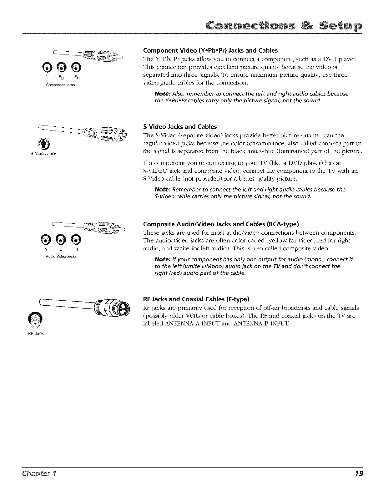
Component Video (Y.Pb*Pr) Jacksand Cables
The Y, Pb, Pr jacks allow you to connect a component, such as a DVD player.
This connection provides excellent picture quality because the video is
separated into three signals. To ensure maximum picture quali/y, use three
video-grade cables tbr tile connection.
Note: Also, remember to connect the left and right audio cables because
the Y.Pb.Pr cables carry only the picture signal, not the sound.
®
S-Video Jack
S-Video Jacks and Cables
The S-Video (separate video) jacks provide better picture quality than die
regular video jacks because the color (chrominance, also called chroma) part of
die signal is separated from the black and white (luminance) part of the picture.
If a component you're connecting to your "IV (like a DVD player) has an
S-VIDEO jack and composite video, connect the component to the "IV with an
S-Video cable (not provided) tbr a better quali_y picture.
Note: Remember to connect the left and right audio cables because the
S-Video cable carries only the picture signal, not the sound.
V L F_
A_dio/Video Jacks
Composite Audio/Video Jacks and Cables (RCA-type)
These jacks are used tbr most audio/video connections between components.
The audio/video iacks are olden color coded (yellow fbr video, red fbr right
audio, and white fbr left audio). This is also called composite video.
Note: If your component hasonly one output for audio (mono), connect it
to the left (white L/Mono) audio jack on the TVand don't connect the
right (red) audio part of the cable.
0
FIF Jack
RFJacks and Coaxial Cables (F-type)
t@'iacks are primarily used fl_r reception of off'air broadcasts and cable signals
(possibly older VCRs or cable boxes). The RF and coaxial iacks on the "IV are
labeled ANTENNA A INPUT and ANTENNA B INPUT.
19
Page 22
CQnn c' @ns S ' up
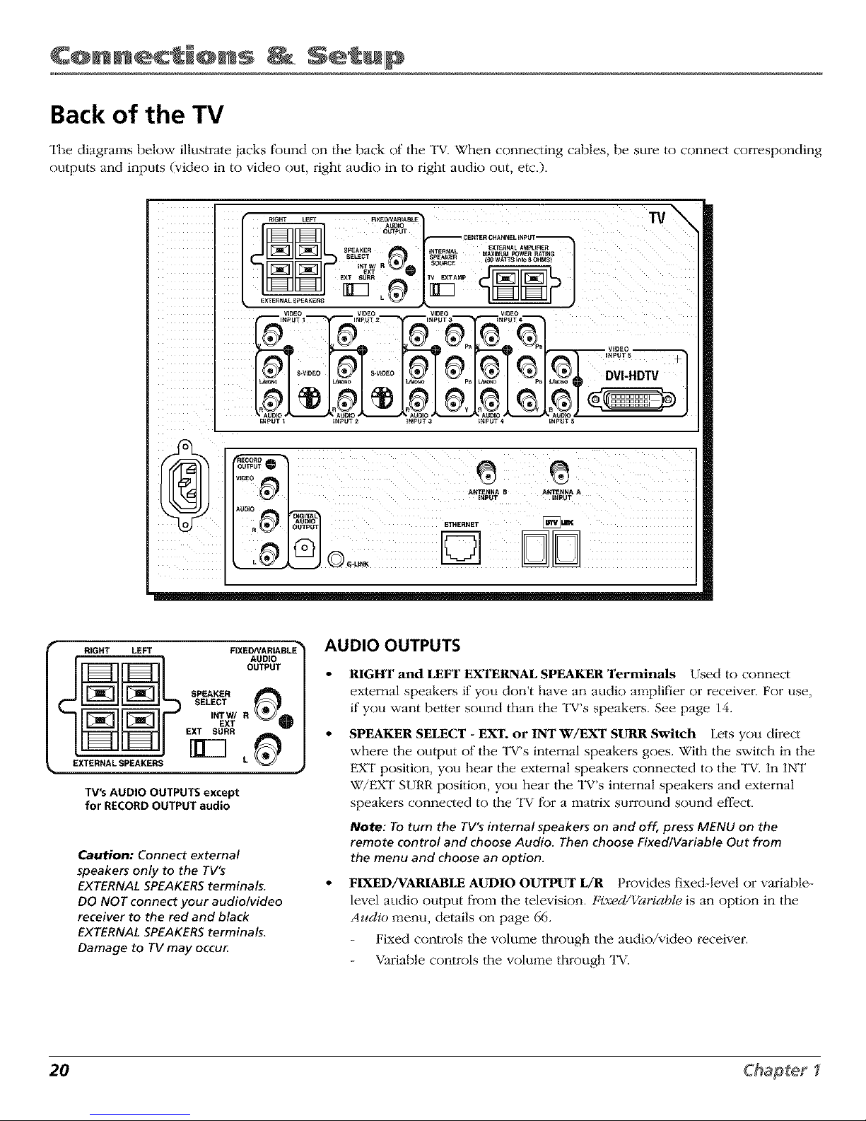
Back of the TV
The diagrams below illustrate jacks fkmnd on the back of the TV. When connecting cables, be sure to connect corresponding
outputs and inputs (video in to video out, right audio in to right audio out, etc.).
d--#
VmEC @
FTHERNET _K,_
o.....
RIGHT LEFT
FIXED/VARIABLE
AUDIO
OUTPUT
SPEARER
SELECT
INTW/ R
EXT
EXT SURR
rg--1
EXTERNALSPEAKERS L
TV's AUDIO OUTPUTS except
for RECORD OUTPUT audio
Caution: Connect external
speakers only to the TV's
EXTERNAL SPEAKERS terminals.
DO NOT connect your audio/video
receiver to the red and black
EXTERNAL SPEAKERS terminals.
Damage to TV may occu_
AUDIO OUTPUTS
RIGHT and LEFT EXTERNAL SPEAKER Terminals Used to connect
external speakers if you don't have an audio amplifier or receiver. For use,
if you want better sound than the TV's speakers. See page 14.
SPEAKER SELECT - EXT. or INT W/EXT SURR Switch Lets you direct
where the output of the TV's internal speakei_s goes. With the switch in the
EXT position, you hear the external speakers connected to the TV. In INT
W/EXT SURR position, you hear tile TV's internal speakers and external
speakei:s connected to tile "IV fbr a matrix surround sound effect.
Note: To turn the TV'_ internal speakers on and off, press MENU on the
remote control and choose Audio. Then choose Fixed/Variable Out from
the menu and choose an option.
FIXED/VARIABLE AUDIO OUTPUT L/R Provides fixed-level or variable-
level audio output from the television. Fixed/Variable is an option in the
Audio menu, details on page 66.
Fixed controls the volume through the audio/video receiver.
Variable controls the volume through _V.
20 Chapter
Page 23
_CENTER CHANNELINPUT =_
INTERNAL
SPEAKER
SOURCE _
TV's CENTER CHANNEL INPUTS
Caution: Do not connect the A/V
receiver's CENTERCHANNEL
output to the TV'sEXTERNAL
SPEAKERSterminals. Damage to
TVmay occu_
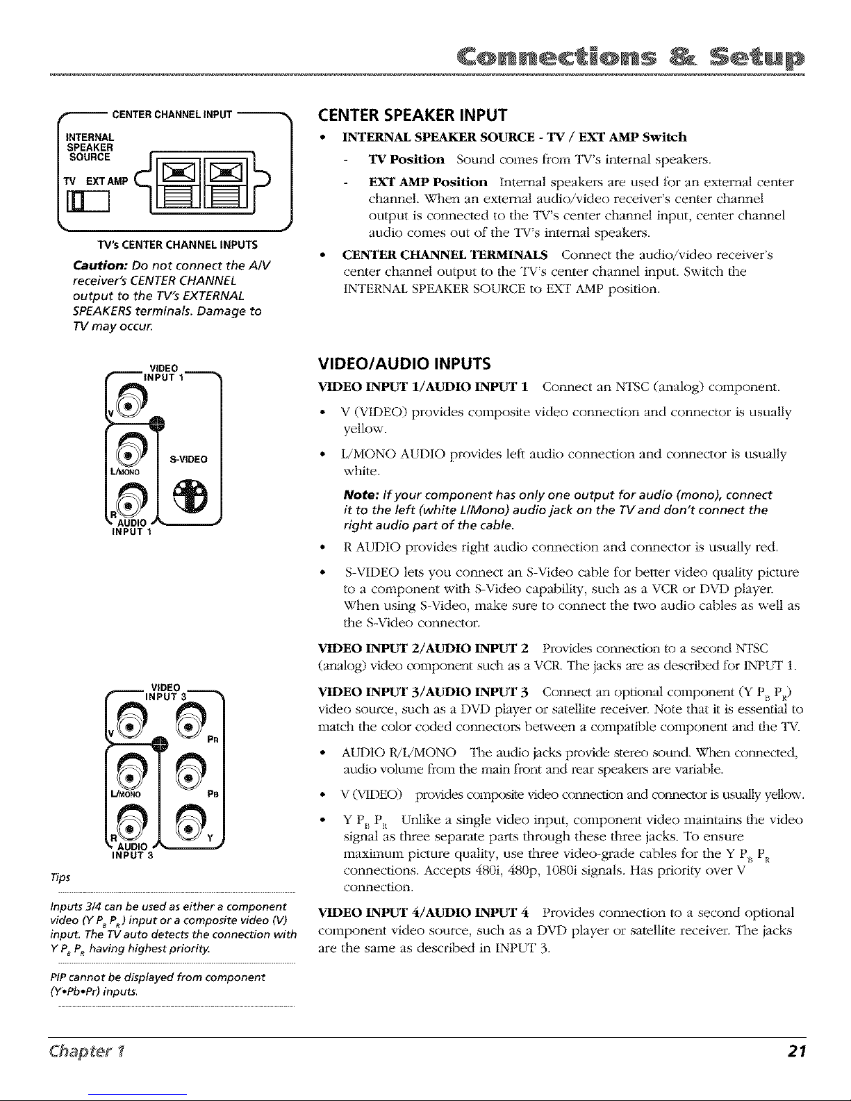
CENTER SPEAKER INPUT
• INTERNAL SPEAKER SOURCE - TV / EXT AMP Switch
"rv Position Sound comes from TV's internal speakei_s.
EXT AMP Position Internal speakers are used tk_ran exlernal center
channel. When an external audio/video receiver's center channel
output is connected to the TV's center channel input, center channel
audio comes out of the TV's internal speakers.
• CENTER CHANNEL TERMINALS Connect the audio/video receiver's
center channel output to the TV's center channel input. Switch the
INTERNAL SPEAKER SOURCE to EXT AMP position.
VIDEO __
INPUT 1
S-VIDEO
®
INPUT 1
INPUT 3
Tips
Inputs 3/4 can be used as either a component
video (Y P8 P_) input or a composite video (V)
input. The TV auto detects the connection with
Y P8PR having highest priorit_
PiP cannot be displayed from component
(Y*Pb*Pr) inputs.
VIDEO/AUDIO INPUTS
VIDEO INPUT l/AUDIO INPUT 1 Connect an NTSC (analog) component.
• V (VIDEO) provides composite video connection and connector is usually
yellow.
• L/MONO AUDIO provides leli audio connection and connector is usually
white.
Note: If your component hasonly one output for audio (mono), connect
it to the left (white L/Mono) audio jack on the TVand don't connect the
right audio part of the cable.
• R AUDIO provides right audio connection and connector is usually red.
• S-VIDEO lets you connect an S-Video cable tBr better video quality picture
to a component with S-Video capability, such as a VCR or DVD player.
When using S-Video, make sure to connect the two audio cables as well as
the S-Video connector.
VIDEO INPUT 2/AUDIO INPUT 2 Provides connection/o a second NTSC
(analog) video component such as a VCR. The iacks are as described fbr INPUT 1.
VIDEO INPUT 3/AUDIO INPUT 3 Connect an optional component (Y P,_PR)
video source, such as a DVD player or satellite receiver. Note that it is essential to
match tile color coded com_ectors between a compatible component and the TV.
• AUDIO 1UL/MONO ]l_e audio jacks provide stereo sound. When com_ected,
audio volume f?om the main front and rear speakers are variable.
• V (VIDEO) provides comp(xsite video cormecdon and connector Lsttsually yellow.
• Y P*_PR Unlike a single video input, component video maintains the video
signal as three separate parts through these three jacks. To ensure
maximum picture quality, use three video-grade cables for the Y P_ PR
connections. Accepts 480i, 480p, 1080i signals. Has priority over V
connection.
VIDEO INPUT 4/AUDIO INPUT 4 Provides connection to a second optional
component video source, such as a DVD player or satellite receiver. The iacks
are the same as described in INPI.IT 3.
21
Page 24
CQnn c' @ns S ' up
INPUT 5
ObTPbT
VIDEO
AUDIO
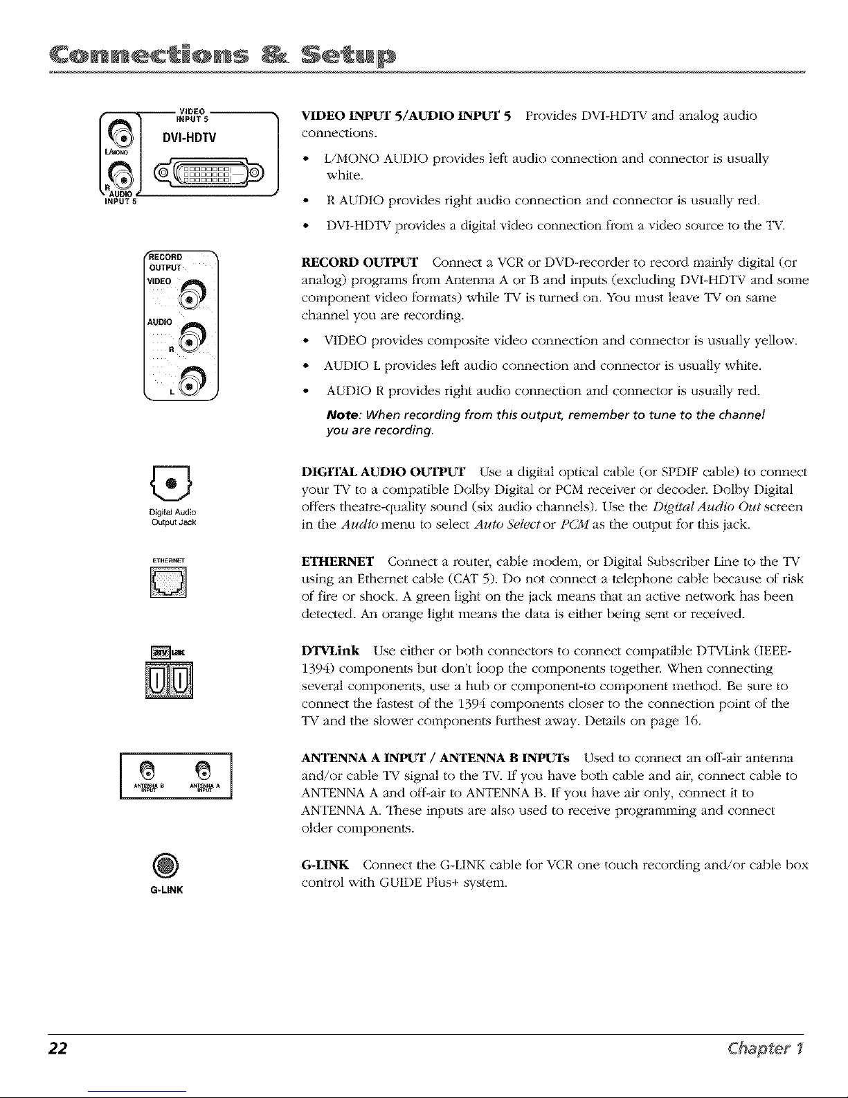
VIDEO INPUT 5/AUDIO INPUT 5
connections.
Provides DV1-HDTV and analog audio
• L/MONO AUDIO provides lef_ audio connection and connector is usually
white.
• R AUDIO provides right audio connection and connector is usually red.
• DVI-HDTV provides a digital video connection from a video source to the TV.
RECORD OUTPUT Connect a VCR or DVD-recorder to record mainly digital (or
analog) programs from Antenna A or B and inputs (excluding DVI-HDTV and some
component video tkmnats) while TV is turned on. You must leave "IV on same
channel you are recording.
VIDEO provides composite video connection and connector is usually yellow.
AUDIO L provides left audio connection and connector is usually white.
AUDIO R provides right audio connection and connector is usually red.
Note: When recording from this output, remember to tune to the channel
you are recording.
Digital Audlo
Output Jack
DIGITAL AUDIO OUTPUT Use a digital optical cable (or SPD1F cable) to connect
your "IV to a compatible Dolby Digital or PCM receiver or decodei: Dolby Digital
offe_:s theatre-quality sound (six audio channels). Use the Digital Audio Out screen
in/he Audio menu to select Auto Selector PCM as the output tbr this jack.
ETH_RNET
D
_IilK
ETHERNET Connect a router, cable modem, or Digital Subscriber Line to/he TV
using an Ethernet cable (CAT 5). Do not connect a telephone cable because of risk
of tim or shock. A green light on/he jack means that an active network has been
detected. An orange light means the dam is ei/her being sent or received.
DTVLink Use eidmr or both connectors to connect compatible DTVLink (IEEE-
1394) components but don't loop the components togethei: When connecting
several components, use a hub or component-to component method. Be sure to
connect/he t_astest of the 1394 components closer to the connection point of the
l_V and the slower components fi.trthest away. Details on page 16.
G-LINK
ANTENNA A INPUT / ANTENNA B INPUTs Used to connect an oflLair antenna
and/or cable "IV signal to the "IV. If you have both cable and air, connect cable to
ANTENNA A and ofl_-air to ANTENNA B. If you have air only, connect it to
ANTENNA A. These inputs are also used to receive programming and connect
older components.
G-LINK Connect the G-LINK cable for VCR one touch recording and/or cable box
control with GUIDE Plus+ system.
22 Chapter I
Page 25
Why You Should Connect the G-LINK Cable
The G-LINK cable enables the GUIDE Plus+ system (the on-screen interactive program guide) to
work wi/h your VCR and/or cable box.
Cable Box - If your TV is connected to a cable box, you must connect the G-LINK cable to receive
"IV program listings tkJryour area and to tune directly to a channel when the program guide is on
your TV screen.
VCR- If your TV is connected to a VCR and you don't connect the G-LINK cable, one-touch VCR
recording and timed recordings won't work. The o/her fk:atures of the guide will work properly.
G.LINK cable
G-LINK wands
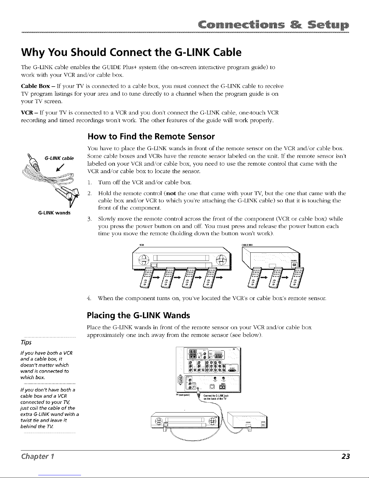
How to Find the Remote Sensor
You have to place the G-LINK wands in front of the remote sensor on the VCR and/or cable box.
Some cable boxes and gcRs have the remote sensor labeled on the unit. If"|he remote sensor isn't
labeled on your VCR and/or cable box, you need to use the remote control that came wi/h the
VCR and/or cable box to locate the sensor.
1. Turn off the VCR and/or cable box.
2. Hold/he remote control (not the one that came with your TV, but the one that came with/he
cable box and/or VCR to which you're attaching the G-LINK cable) so that it is touching the
front of the component.
3. Slowly move the remote control across the front of the component (VCR or cable box) while
you press/he power button on and o1_ You must press and release the power button each
time you move the remote (holding down the button won't work).
4. When |he component turns on, you've located the VCR's or cable box's remote sensor.
Tips
If you have both a VCR
and a cable box, it
doesn't matter which
wand is connected to
which box_
If you don't have both a
cable box and a VCR
connected to your T_,
just coil the cable of the
extra G-LINK wand with a
twist tie and leave it
behind the T_
Placing the G-LINK Wands
Place the G-LINK wands in front of the remote sensor on your VCR and/or cable box
approximately one inch away from the remote sensor (see below).
23
Page 26
CQnn c' @ns S ' up
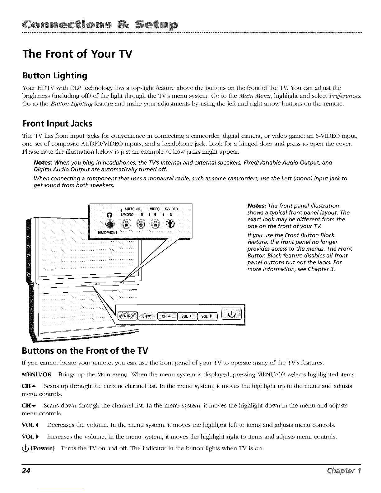
The Front of Your TV
Button Lighting
Your HI-)TV with DLP technology has a top-light t_ature above tile buttons on tile front of tile TV. You can adiust/he
brighmess (including off') of/he light through/he TV's menu system. Go to the Main Menu, highlight and select Prcfi.rences.
Go to the Button Lighting feature and make your adiustments by using the lef_ and right arrow buttons on the remote.
Front Input Jacks
The TV has fi'ont input jacks for convenience in connecting a camcorder, digital camera, or video game: an S-VIDEO input,
one set of composite AUDIO/VIDEO inputs, and a headphone jack. Look fbr a hinged door and press to open the cover.
Please note the illustration below is iust an example of how jacks might appear.
Notes: When you plug in headphones, the rV's internal and external speakers,Fixedlgariable Audio Output, and
Digital Audio Output are automatically turned off.
When connecting a component that usesa monaural cable, suchassome camcorders, use the Left (mono) input jack to
get sound from both speakers.
i I-AU[_OiN7 VIDEO S-VIO_O
L!MONO R I N I N l
HEAVE _ @_
Notes: The front panel illustration
shows a typical front panel layout. The
exact look may be different from the
one on the front of your TIZ
If you use the Front Button Block
feature, the front panel no longer
provides access to the menus. The Front
Button Block feature disables all front
panel buttons but not the jacks. For
more information, see Chapter 3.
Buttons on the Front of the TV
If"you cannot locate your remote, you can use the front panel of your TV to operate many of the TV's t_eatures.
MENU/OK Brings up the Main menu. When/he menu system is displayed, pressing MENU/OK selects highlighted items.
12tI_ Scans up through the currant channel list. In/he menu system, it moves the highlight up in the menu and adjusts
menu controls.
Ctlv Scans down through the channel list. In/he menu system, it moves the highlight down in the menu and adjusts
menu controls.
¥OI,4 Decreases the volume. In/he menu system, it moves the highlight let'_to items and adjusts menu controls.
¥OI, F Increases the volume. In/he menu system, it moves the highlight right to items and adjusts menu consols.
(Power) Turns the TV on and oil'. The indicator in the button lights when "IV is on.
24 Chapter
Page 27
Plug in the TV
Plug the fiat end of the cable into the power jack on the back of the "FV.Then plug the other end
of the power cord into an appropriate wall outlet. Be sure to insert the plug completely. Do not
plug into an outlet controlled by a light switch.
Note: When you first plug your TV into an outlet, the Power indicator on the front panel
will light for approximately 15 seconds and then go off during the initialization of the TV
The TV can only be turned on after the Power indicator goes off. This happens every time
power is reapplied to the TV
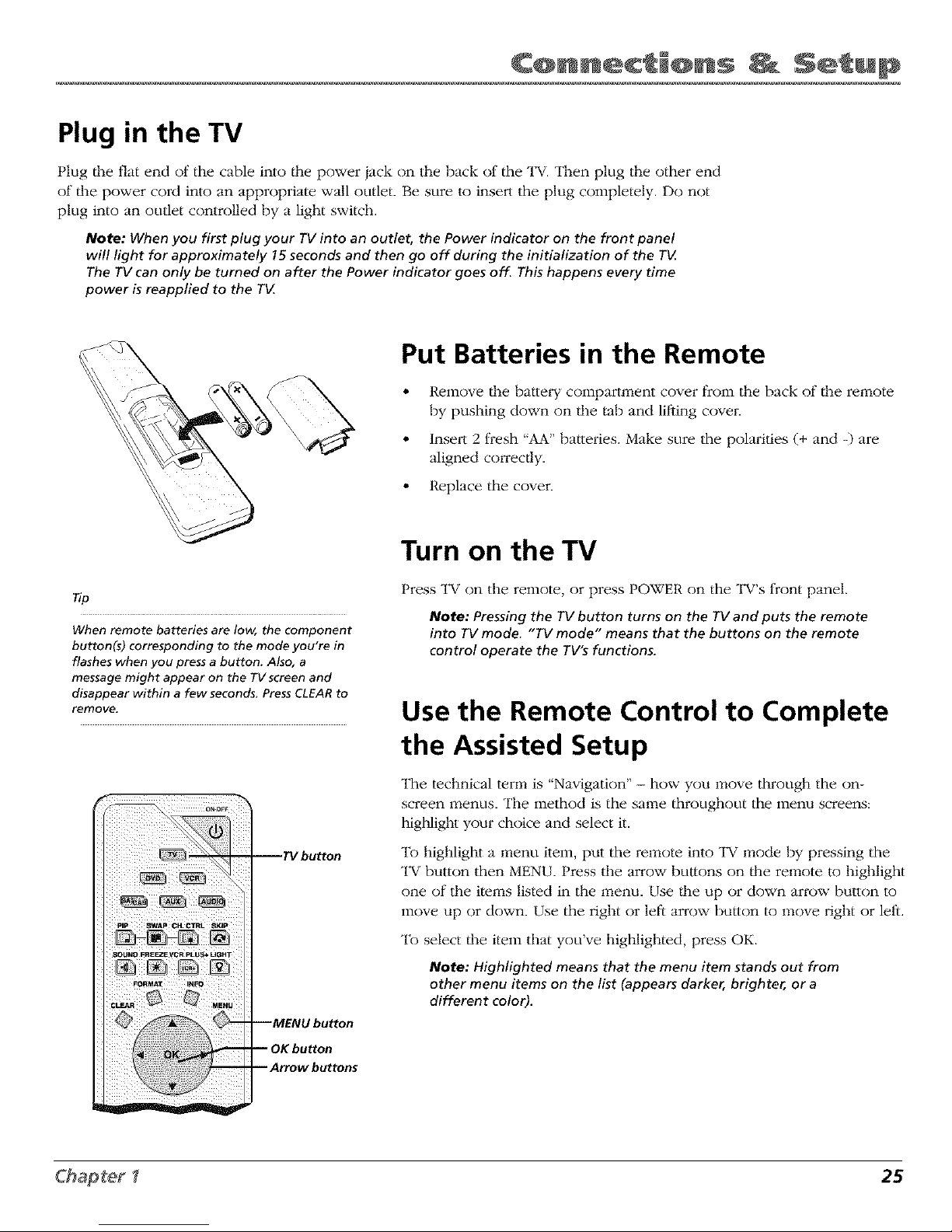
Put Batteries in the Remote
Remove/l_e battery compartment cover from the back of tl_e remote
by pushing down on the tab and lifting cover.
Insert 2 fresh "AA" batteries. Make sure the polarities (+ and -) are
aligned con'ec/ly.
• Replace the cover.
_p
When remote batteries are low, the component
button(s) corresponding to the mode you're in
flashes when you press a button. Also, a
message might appear on the TV screen and
disappear within a few seconds. Press CLEAR to
remove.
pip swap CH. C'[RL ,_p
SOUND F'R_E VCR pLUS+ UGHT
FORMAT INFO
TV button
Turn on the TV
Press TV on the remote, or press POWER on the TV's front panel.
Note: Pressingthe rv button turns on the rv and puts the remote
into TV mode. "TV mode" means that the buttons on the remote
control operate the TV'sfunctions.
Use the Remote Control to Complete
the Assisted Setup
The technical term is "Navigation" - how you move through the on-
screen menus. The method is the same throughout the menu screel_s:
highlight your choice and select it.
To highlight a menu item, put the remote into "IV mode by pressing the
TV button then MENU. Press the arrow buttons on/l_e remote to highlight
one of the items listed in the menu. Use/lie up or down arrow button to
move up or down. Use the right or left arrow button to move right or leli.
"12)select the item that you ve hlghhghted, press OK.
Note: Highlighted means that the menu item stands out from
other menu items on the list (appears darker, brighter, or a
different color).
25
Page 28
CQnn c' @ns S ' up
Tip
To access the setup menus, press MENU and
choose Assisted Setup.
Complete the Assisted Setup
Your TV's menu system allows you to adjust your TV's f_atures to be
configured to work properly. On-screen information helps you choose set/ings
to match your setup. The t_rst time you turn on your TV,/he AssisWd Setz_p
screens appear automatically. Select Begin Setup to start or select Cancel Setup
to exit.
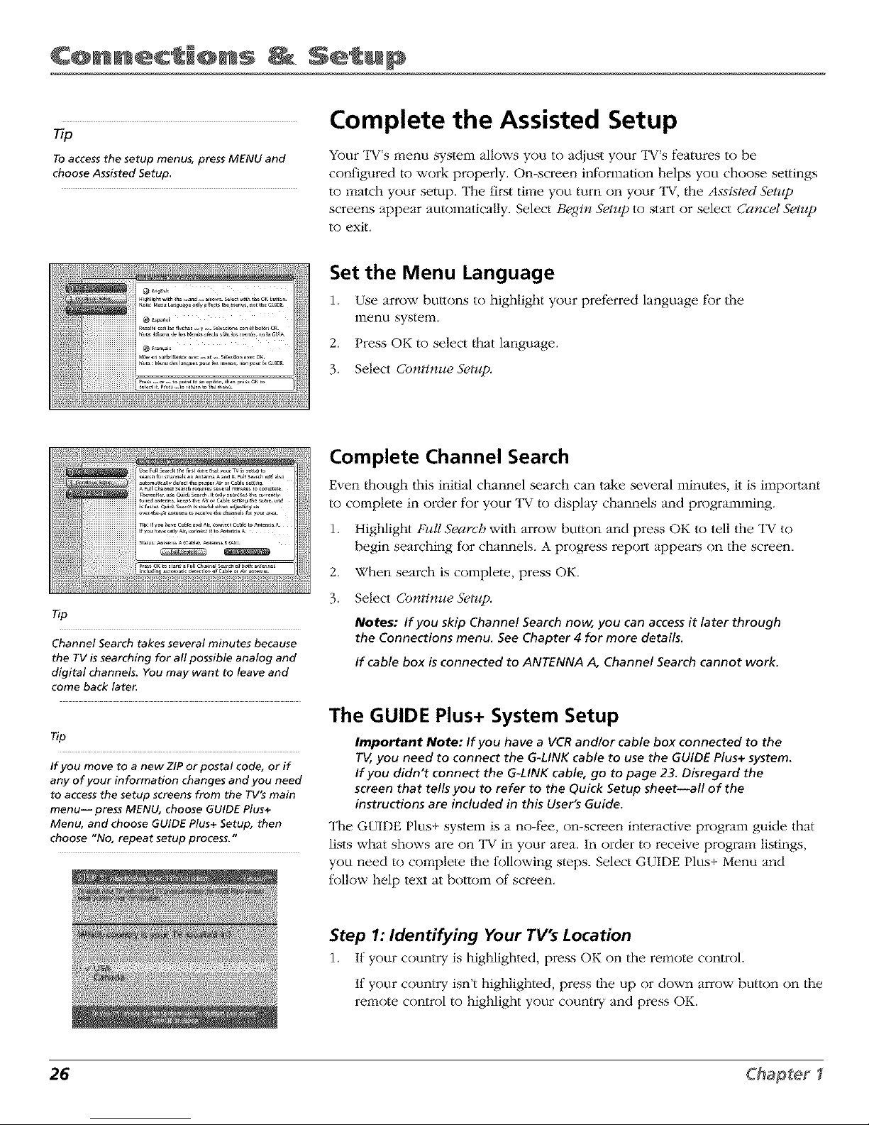
Set the Menu Language
1. Use arrow buttons to highlight your prefi_rred language f_Jrthe
menu system.
2. Press OK to select that language.
3. Select Continue Setup.
Tip
Channel Search takes several minutes because
the TV is searching for all possible analog and
digital channels. You may want to leave and
come back latex
Tip
If you move to a new ZIP or postal code, or if
any of your information changes and you need
to access the setup screens from the TV's main
menu-- press MENU, choose GUIDE Plus+
Menu, and choose GUIDE Plus+ Setup, then
choose "No, repeat setup process."
Complete Channel Search
Even/hough this initial channel search can take several minutes, it is i_:r_pormnt
to complete in order fkJryour "I_Vto display channels and programming.
1. Highlight Full Search with arrow button and press OK to tell the TV to
begin searching for channels. A progress report appears on the screen.
2. When search is complete, press OK.
3. Select Continue Setup.
Notes: If you skip Channel Searchnow, you can accessit later through
the Connections menu. SeeChapter 4 for more details.
If cable box isconnected to ANTENNA A, Channel Searchcannot work.
The GUIDE Plus+ System Setup
Important Note: If you have a VCRandlor cable box connected to the
TV,you need to connect the G-LINK cable to use the GUIDE Plus+ system.
If you didn't connect the G-LINK cable, go to page 23. Disregard the
screen that tells you to refer to the Quick Setup sheet--all of the
instructions are included in this User's Guide.
The GUIDE Plus+ system is a no-fi_e, on-screen interactive program guide that
lists what shows are on TV in your area. In order to receive program listings,
you need to complete/he following steps. Select GUIDE Plus+ Menu and
follow help text at bottom of screen.
Step 1: Identifying Your TV's Location
1. If your country is highlighted, press OK on the remote control.
If your counti T isn't highlighted, press the up or down arrow button on the
remote control to highlight your country and press OK.
26 Chapter
Page 29
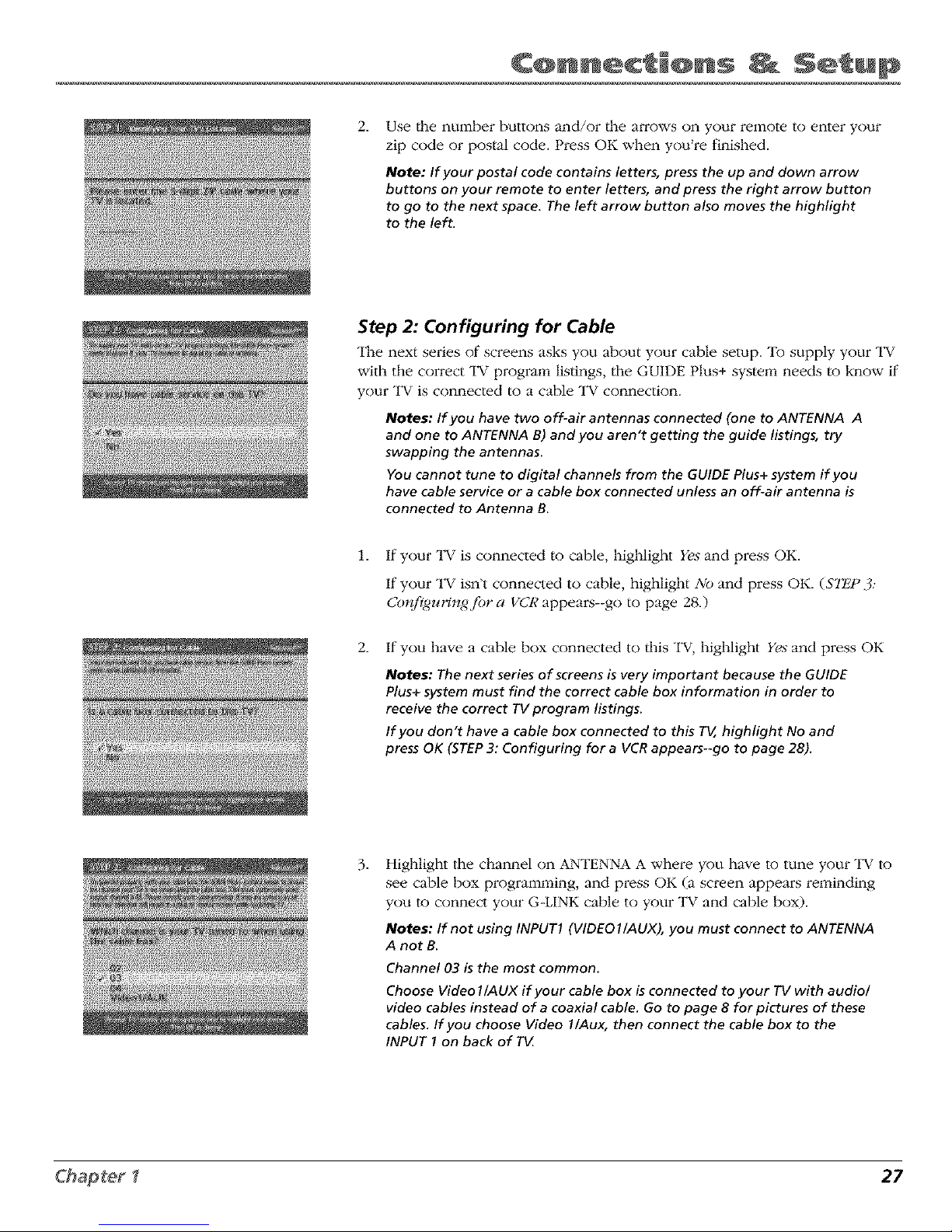
2.
Use |he nuinber buttons and/or _he a_ows on your remote to enter your
zip code or postal code. Press OK when you're finished.
Note: If your postal code contains letters, press the up and down arrow
buttons on your remote to enter letters, and press the right arrow button
to go to the next space. The left arrow button also moves the highlight
to the left.
Step 2: Configuring for Cable
The next series of screens asks you about your cable setup. To supply your "IV
with the correct "IV program listings, the GUIDE Plus+ system needs to know if
your TV is connected to a cable l_V connection.
Notes: If you have two off-air antennas connected (one to ANTENNA A
and one to ANTENNA B) and you aren't getting the guide listings, try
swapping the antennas.
You cannot tune to digital channels from the GUIDE Plus+ system if you
have cable service or a cable box connected unless an off-air antenna is
connected to Antenna B.
1. If your TV is connected to cable, highlight Yes and press OK.
If your TV isn't connected to cable, highlight No and press OK. (STE;P 3:
Configuringfi)r a VCR appears--go to page 28.)
2. If you have a cable box connected to/his "IV, highlight Yes and press OK
Notes: The next series of screens is very important because the GUIDE
Plus+ system must find the correct cable box information in order to
receive the correct TV program listings.
If you don't have a cable box connected to this TV, highlight No and
press OK (STEP3: Configuring for a VCR appears--go to page 28).
.
Highlight tile channel on ANTENNA A where you have to tune your "IV to
see cable box programming, and press OK (a screen appears reminding
you to connect your G-LINK cable to your l_V and cable box).
Notes: If not using INPUT1 (VIDEO1/AUX), you must connect to ANTENNA
A not B.
Channel 03 is the most common.
Choose Video l /AUX if your cable box is connected to your TV with audio/
video cables instead of a coaxial cable. Go to page 8 for pictures of these
cables. If you choose Video 1/Aux, then connect the cable box to the
INPUT I on back of T_
27
Page 30

CQnn c' i@ns S ' up
4.
Highlight your brand of cable box, and press OK.
If your brand isn't listed, highlight Not Listed and press OK.
Important Note: Cable box may only be connected to ANTENNA A or
INPUTI if it is to be controlled by GUIDEPlus+ system.
5.
Make sure your cable box is on.
Tune/he cable box to channel 02 (use the remote control that came with
your cable box, or press/he channel buttons on the cable box).
Press OK (the GUIDE Plus+ system starts testing codes).
Important Note: When code testing is in progress, don't touch your TV,
VCR,cable box or any of the remote controls for these products.
.
Look at your cable box. If it is still on and changed to channel 09, the test
was successful. Highlight Yes, and press OK ($7_2P 3: Configuringfi_r a VCR
appears).
If your cable box didn't change to channel 09 or turned itself off, you have
two choices: No and Test this code again.
Test this code again: If you think the l_V, the cable box, or any of the
remote controls might have been touched or bumped during the test,
highlight 7_st this code a<_ainand press OK (the GUIDE Plus+ system runs
/he same set of codes).
No: If you don't think the test was interrupted, highlight No and press OK
(GUIDE Plus+ system tests the next code).
Repeat/he previous instructions until the "IV finds/he correct cable box
code. Follow the instructions on/he screen.
Note: If the TVcan't find your cable box code, a troubleshooting checklist
appears. Carefully review each checklist and follow the instructions on the
screen.
.......
£
;_: y<!_<g,
Step 3: Configuring for a VCR
1. If"your "IV is connected to a VCR, press OK (a screen appears reminding
you to connect your G-LINK cable to your TV and VCR).
If it is not, highlight No and press OK. Go to Step 4: Confirming Your
Settings on page 29.
28 Chapter
Page 31

2. Use/he up and down arrow buttons to highlight the brand of your VCR
that is connected to the TV and press OK.
If your brand isn't listed, highlight Not Listed and press OK.
.
Keep the VCR on. When you complete these steps, press OK to begin
testing.
Important Note: When code testing is inprogress, don't touch your TV,
VCR,or any of the remote controls for these products.
Tip
Leave your cable box turned ON to download
program information.
Leave your VCR turned OFF to record programs.
4.
Look at/he front of your VCR. If your VCR stopped playing the tape, the
test was successfid. Highlight Yes and press OK.
If your VCR didn't stop playing a tape, you can either choose No or Test this
code again.
If you think your TV or remote might have been touched during/he test,
make sure the VCR is on and playing a tape. Highlight Test this code a_ain.
If you don't/hink/he test was interrupted, highlight No. Make sure/he VCR
is playing a tape and is on. Press OK (the GUIDE Plus+ system starts testing
anodmr set of codes.)
Keep fbllowing the previous instructions until the TV finds the
correct code fbr the VCR.
Note: If the GUIDEPlus+systemcan't locate the correct code for the VCR,a
list of troubleshooting instructions appears to help you before you try again.
• Try VCRconfiguration again: repeat VCRsetup.
• Testalternate codes: tests selected brands and if this fails, the test
continues with all codes in the system.
• Skipthisstep:theGUIDEPlus+systemwon'tbeabletoautomatically
schedule programs to record on your VCR.
Step 4: Confirming Your Settings
1. Check to make sure all settings are complete and correct. If"all settings are
complete, highlight Yes, end setup and press OK. If your cable box and/or
VCR code testing IMled, you should see INCOMPLE'lli where the cable
box and VCR codes are listed. Once setup is complete, additional
screens appear.
Disregard the screen that tells you to rel;er to/l_e Quick Setup sheet because
there is no sheet packed with/his "IV.
If any settings are incomplete or incorrect, highlight No, repeat setup process
and press OK. Follow/he instructions on the screen.
29
Page 32

CQnn c' @ns S ' up
What to Expect
The next time you turn on your TV al_er setting up/he GUIDE Plus+ system, the guide will
appear on/lie screen. The tk)llowing examples explain what you might see:
• If all of tile program inlk)rmation has been sent to your "IV, the GUIDE Plus+ system appears
with all of your TV program listings.
• If/he program inlk_rmation hasn't been sent to your "IV yet, an ou/line of the GUIDE
(without TV program listings) will appear on the semen. Program information is usually sent
to your "IV at night.
• If morn than one cable company services your area, you may be prompted with a Channel
Mapping screen after the first GUIDE Plus+ system download. You will need to identify your
cable company by selecting/he correct channel numbers t_Jr/lie stations in question.
Features of/lie GUIDE Plus+ system are explained in Chapter 3.
To clear/lie guide from your semen, press CLEAR or GUIDE on/lie remote control.
Changing Channels
1-)epending upon the type of signals you have connected to your HDTV, you might notice/hat
/lie channels change slower than you're used to. This is perfk_ctly normal. Your HDTV is able to
interpret and display both analog (NTSC) and digital (ATSC) signals and the digital subchannels
(when available). Also, you may notice that the size of/lie Channel Banner changes as you scan
/llrough analog and digital channels.
Turning the TV On and Off
Your H1-)TVis equipped with a lamp system that is part of the technology that enables us to
design such a thin, light-weight "IV with a crisp, bright picture. To prolong the life of the lamp,
/lie TV must properly warm up and cool down. Themlk)re, the "IV doesn't turn off"completely
right away-- it lades from blue to black. In case you accidentally turn o1_"/lie TV, you can still
turn it on while the screen is blue. Once the screen goes black, the lamp's cool-down cycle
begins (you may hear a slight humming noise as the lamp cools down). If you tiT to turn on the
TV during the cool-down cycle, the power light on the front of the l_V will blink to alert you that
you need to wait (when the cool-down cycle is complete_-about 30 seconds--the TV turns back
on automatically).
Next Steps
Now that you've finished/he Assisted Setup, you're ready to watch l_V.This might be a good time
to program your remote control. The remote control/liar came with/his "IV can be programmed
to operate other components. Go to the next chapter to find out how to program your remote.
• Chapter 2: Using the Remote Con_ol
• Chapter 3: Using die TV's Features
• Chapter 4: Using the TV's Menu System
• Chapter 5: RelZerence
30 Chapter I
Page 33

Chapter 2
Overview:
• The Buttons onthe Remote Control
• Programming the Remote to Operate Other Components
• How To Use theRemote After You've Programmed It
O •
Remote Code List
; _ ; _ _ ;
Graphics contained within this publicati< n are fi r representation <nly. 31
Page 34

Using Con' r@lM
The Buttons on the Remote Control
Green
action
buHon
Blue
action
button
PIP SWAP GH:CTRL SKIP
_,OURD FREEZE VCR PLUS+ UGHT
PAUSE
Blue Action Button In d_e GUIDE Plus+ system, activates features (located
in the Action bar on TV screen).
Green Action Button In the GUIDE Plus+ system, activates features (located
in the Action bar on TV screen).
LIGHT (9@_)) Press to illuminate some of the remote conu'ol's buttons. "R)
conserve battery power, the light turns off after several seconds. Backlight
won't activate if batteries are low, but blinks on and off quickly.
(0-9) Number Buttons Enter channel numbers and time settings. Also used
in the GUIDE Plus+ system and in the TV menu to make selections.
ANTENNA Switches between Antenna A and Antenna B. In the VCR mode,
functions as a TV/VCR button. In SAT mode, functions as a TV/SAT button.
Arrows (up, down, left, righO Used to move through the on-screen menus.
Also moves the PIP window, see page 56 fbr more information.
AUDIO Places the remote in audio mode to operate a component (such as a
audio receiver, or amplifier receiver) that you've programmed to work with this
button.
AUX Places tile remote in auxiliary mode to operate a component (such as a
cable box, satellite receiver, VCR, DVD, or audio receiver) fllat you've
programmed to work with this button. AUX by del3ult is set up fbr a second
RCA VCR.
CH + or CH - Scrolls up or down through the channel or input list. Press
once to change file channel up or down; press and hold to continue changing
channels. In Ille GUIDE Plus+ system and some menus, scrolls a page at a
time.
CH CTRL (Channel control) Toggles the channel control between the main
TV picture and the PIP window. Use channel up, channel down, INPUT,
component buttons, or number buttons to change channels in PIR You can tell
which picture changes by looking at the channel banner. CH CTRL is marked
by a triangle (_>) in the banner.
CLEAR Removes on-screen menus and displays. Cancels the commercial skip
timer. Quits/he browser.
DVD Places fl_e remote in DVD mode. If Auto Tuning is enabled, pressing
the DVD button turns on the TV and tunes to/he correct Video Input Channel.
FORMAT Toggles through the 4:3 video screen ibrmats (Normal, Zoom, and
Tips Stretch) t_/r some 4:3 signals--not applicable to 16:9 signals. In browser mode,
The VCR, DVD, AUDIO and SAT/GdB buttons toggles/hrough three different view sizes: full-size video, video window on the
also turn on most RCA, GE,and Proscan left, and video window on the right.
products.
FREEZE Preezes entire screen, including tile main picture and PIP window, if
Some remote buttons are used with the Web PIP is displayed. Does not support all inputs. Freezes RECORD OUPUT [)tit not
Browser and have different functions; see page 1394 output.
59 for details.
GO BACK Returns you to tile previous channel or previous screen in tile
menu system. Also, toggles between antenna and input sources.
32
Page 35

Us n@ Con' r@lM
Tips
The component button corresponding to the
mode you're in flashes when the remote
batteries are low and you press a button on the
remote. A warning banner may also appear on
the screen when you press a remote button and
your batteries are low
To turn off most RCA, GE, and Proscan
components that are connected to the TV, press
ON*OFF twice within two seconds and hold
remote steady until indicator turns off.
This feature only works with most RCA, GE, and
Proscan products.
GUIDE Brings up the Listings screen fbr/he GUIDE Plus+ system.
INFO Brings up the Channel Banner wi/h channel and viewing inlbnnation.
Press again to remove the banner. In the GUIDE Plus+ system, brings up more
program infbrmation.
INPtrr Toggles through the TV's available input sources (Front Input,
INPUT 1, INPUT 2, INPUT 3, INPUT 4, INPUT 5, DTVLink (if available), last-
active antenna).
MENU Makes Main Menu appear and disappear.
MUTE Reduces/he TV's volume to its minimum level. Press again to restore
volume.
OK When a menu item is highlighted, press OK to select/he item.
ON.OFF Turns/he TV on or off. Your HDTV is equipped with a special lamp
system. In order to preserve the life of the lamp, the "IV must warm up and
cool down properly when you turn the "IV on and off. When you turn/he TV
off, the screen turns blue and t;ades to [)lack. While/he screen is blue, you can
still turn the TV back on. If the screen is [)lack and the light on the front of the
"IV [)links when you try to turn it on, the l_V's lamp is in its cool-down cycle--
wait about 30 seconds and then the "IV will turn back on automatically.
In other modes (VCR, DVD, SAT/CAB, AUX, AUDIO), if programmed, turns the
component on and off.
PIP Makes the PIP window appear and disappear (See Chapter 3 tbr more infom_ation about using PIE) Locks/unlocks
video window in GUIDE Plus+ system.
REVERSE, PLAY, FORWARD, RECORD, STOP, PAUSE If programmed, provides transport control tbr some remote-
controllable VCKs and DVD playeI:s. In "IV mode, can control 1394 component when tuned to the 1394 input.
SAT/CAB Places the remote in SAT/CAB mode. If Auto Tuning is enabled, turns on the I_V and tunes it to the correct
Video Input Channel.
SKIP Press once before changing channels and the TV returns to/he original channel after 30 seconds. Press repeatedly to
add more time. Cannot be used with the browser. Use CLEAR to cancel.
SOUND On digital channels/inputs, toggles the audio language (if available fbr that channel). For analog channels, toggles
SAP on or off. Does not affect default menu settings tbr SAP or Audio Language.
SWAP When using PIP, switches the main picture wi/h the PIP window.
TV Places the remote in "IV mode. Turns on the I_V and tunes to the last-viewed TV channel or input.
VER Places the remote in VCR mode. If Auto Tuning is enabled, turns on the "IV and tunes to the VCR Video Input
Channel.
VCR PLUS+ Only used wi|h RECORD OUTPUT jacks. Press VCR PLUS+ to set a one touch recording when a VCR is
connected to the RECORD OUTPUT jacks--not a 1394 recording.
VOL - or VOL + Decreases or increases the TV's w)lume. The TV Audio Output menu must be set to Variable Speakers On.
33
Page 36

Using Con' r@lM
STOP
You'll use these buttons when
you program the remote for
other components.
Important Note: The remote may
not be compatible with all models
of all brands of components. It
also may not operate all functions
of your component.
By default, the AUX button is programmed for
a second RCA VCR. If auto tuning is set up, it
will tune to VCR2 input channel.
Programming the Remote to Operate
Other Components
The universal remote can be programmed to operate many brands of remote-
controllable VCRs, audio components, DVD players, cable boxes, satellite
receivei:s and oilier components. In addition to being programmed to operate
your television, it's already programmed to operate most RCA, GE, and Proscan
componenls.
The AUX button can be programmed to operate most brands of an additional
remote-controllable component: satellite receiver, cable box, DVD, VCR, and
audio.
Note: The TV button can't be programmed on this remote to control any
component; it controls only this T_
Find Out If You Need to Program the Remote
To determine whether/l_e universal remote needs to be programmed to
operate one of the components connected to your TV, such as a VCR, do/he
fkJllowing:
1. Turn on the component (in this example, a VCR).
2. Point the remote at the component.
3. Press the corresponding component button (in this example, VCIO.
4. Press ON*OFF to see if the VCR responds. If the VCR doesn't respond,
you need to program the remote to operate it.
Programming the Remote
There are two ways to program d_e remote control to operate other
components: Direct k'nt_ and Automatic Code 5>arch.
Using Direct Entry
1. Turn on the component you want to operate (VCR, DVD playei, etc.)
2. Look up the brand and code nmnber(s) f_)r _he component on the code list
in this section.
3. Press and hold the component button you want to program on fire remote.
4. Enter the 4-digit code from the remote control code list on the tBllowing
pages. If the indicator flashes, you have either entered an invalid code or
the button isn't programmable.
5. Release the component button, point remote at component, and then press
ON*OFF to see if the component responds to the command. If it doesn't,
try pressing the component button and then ON*OFF again.
* If you get no response, repeat these steps using the nexl code listed tkJr
your brand, until the componenl responds to/lie remote commands.
* If you try all the codes tk)r your component brand and none work,/ry/he
automatic code search mefllod. If automatic code search doesn't find the
code, the remote is not compatible with your component.
34
Page 37

Using Con' r@lM
Using Automatic Code Search
Note: The AUX button can only search VCR codes, but can be used for a non-VCR device by
programming it with direct entry method.
If"Direct Entry does not work f_Jr your component, uy Auto Code Search. The t_llowing instructions can be
used to program the remote to operate each of your components. If you want to stop the automatic code
search without programming any of your components, press and hold CLEAR until the indicator on the
remote turns off.
1. Turn on the component you want to operate (VCR, DVD playeI; etc.)
2. Press and hold the component but/on you want to program (VCR, DVD, etc.). While holding the
component button, press and hold ON.OFF until the component button on the remote turns on, then
release both buttons.
3. Point the remote at the component.
4. Press and release PLAY, then wait 5 seconds or until the component button stops flashing.
A/this point the remote is searching fBr the correct code to program. If, afier 5 seconds, the component
you want to operate does not turn off, press PLAY again to tell the remote to search the nexl set of
codes.
Continue pressing and releasing PLAY until the component turns off or you have searched through all
of the codes. The component buttons flash when all codes have been searched, the component button
turns off, and remote exits Automatic Code Search.
If the component you want to control does turn off:
1. Press and release REVERSE, then wait 2 seconds. Repeat this step until the component turns back ON.
2. To f'mish, press and hold KFOP until the component button on the remote turr_s olt'.
To stop the automatic code search without
programming any components, press and hold
CLEAR until the indicator on the remote turns
off.
Some of the remote's buttons might operate
differently for other components, especially when
you're using another component's menu system.
How to Use the Remote After You've
Programmed It
Because this univei:sal remote can con_ol several diflk:rent components (TV,
DVD, VCR, satellite receiver, etc.), it uses operational modes/riggered by the
component buttons.
1. Press the appropriate component button (DVD, TV, VCR, SAT/CAB,
AUDIO, AUX) to set the remote to control the component.
2. Press ON,OFF to turn the component ON or OFF.
3. Use the remote buttons that apply to that component.
Notes: The remote control may not be compatible with all brands and
models of components.
If you keep pressing buttons and nothing happens, the remote is
probably in the wrong mode. You must press the component button
that matches the component you want to operate (i.e., if you want to
operate the VCR, press VCR on the remote control to put the remote in
VCR mode.)
35
Page 38

Using Con' r@lM
The Learning Feature
Before using the learning feature, make sure this TV's remote control is programmed to control
other components you have connected to the "FV.Programming the remote control erases all
learned commands for that component mode.
Alter you program the TV's remote control to operate the other component, the TV's remote
provides most of the operations you need. However, there may be some fimctions on the
component's original remote control that your TV's remote control doesn't have. For example, your
DVD remote control might have a ZOOM button that enables you to enlarge the picture, but your
"IV remote doesn't have that button. The learning l;eature enables you to record the fianctionality of
a specific button from the original remote control to one of the TV's remote control buttons.
Note: All learned functions for a mode can be erased if you program a different component
to that mode.
Up to 2 inches apart
Adding a Learned Function
There are several things to consider belk)re you begin the learning process:
• You can't record a learned function to the fkJllowing buttons on the "FV's remote control:
component buttons (TV, VCR, DVD, SAT/CAB, AUX, and AUDIO), the CLEAR button, and the
LIGHT button.
• Before adding a Learned Function, you must program this TV's remote control to operate that
component because programming/he remote control erases all learned commands for that
component mode.
• Do the learning process in low light areas because too much natural light or fluorescent light
might cause the learning lkmture to fail because the remote control functions are recorded
(learned) by sending infrared (IR) signals.
• The TV's remote and the original remote should be no more than 2 inches apart.
In order to record (learn) a fimction t¥om one remote to/he other, you must make sure the
Infi'ared (IR) transmitter of the original remote is t;acing the IR receiver on/he top of the laT's
remote (see illustration). To accomplish this, you may have to hold a remote in each hand
instead of laying both on the table.
The learned buttons are mode specific--if you add a button function from your DVD player's
remote control, you must press the DVD button fii:st before the learned fimction will work (in
"IV mode, the button where you've stored the learned timction will continue to work as it
always has).
36
Page 39

Using Con' r@lM
1. Press and hold/he component button on the l_V's remote that applies to the function you will be
adding (DVD, VCR, SAT/CAB, AUDIO, or AUX). The component button lights.
2. On/he TV remote, press and hold/he RECORD button.
3. Keep pressing bo/h of/he buttons (the component but/on and tile RECORD button) until the
component button light turns off, flashes, and turns oil'. Release both but/ons.
4. On/he TV's remote control, press and release the button where you want to store/he new function
0he component button turns off and then back on).
Note: If you press an invalid button on the TVremote, one of the component button flashes 4 times
to alert you. You'll have to repeat step 4.
5. With the remote controls facing each other and no more than 2 inches apart, press and hold the
button of the component's remote control that has the functionality you are recording to the TV's
remote control. Keep pressing/he button until/he TV remote's component button light turns off and
back on (the function has been saved to the "IV remote).
6. The TV remote control remains in 'learning mode" so you can continue adding functions to
difl;erent buttons by repeating steps 4 and 5. Oi; press CLEAR to exit learning mode.
Notes: If you want a new function on a button, you must record (learn) over it.
The amount of memory each learned function uses in the TV's remote control varies. If your TV
remote is out of memory, the component button(s) light flashes 4 times and turn off, exiting you from
the Learning mode.
Clearing a Learned Function
To delete a learned button function, use |he procedure bek)w.
1. Press and hold the component but/on 0he component but/on lights). Then press and hold/he CLEAR
button lk)r 3 seconds. Continue depressing both buttons (the component mode button flashes--turns
on and off again).
2. Release/he component and CLEAR buttons (the component button being programmed turns on).
Remote is now in Clear learned function mode.
3. Press and release the button where learning is to be cleared. The component button blinks off then
back on the learned flmction was cleared successfully.
4. Repeat steps 1 through 3 until all buttons' learned functions have been cleared.
Note: If an invalid button is pressed, the component mode button(s) flashes 4 times and the selected
component button stays on and remote remains in Clear Learned Function mode. Repeatstep 3.
5. Press the CLEAR button and your TV remote returns to its original operation mode.
Deleting ALL Learned Functions
This procedure erases all learned functions in every component mode of |he remote.
1. Press and hold the CLEAR button (the current component button lights). Then press and hold/he
ON*OFF button (component button light turns off tk)r 3 seconds, flashes, turns on and off) while
continuing to hold CLEAR.
2. Release bo/h buttons (current component button turns on).
3. Press any component button to delete all learned fimctions in all modes. Remote is automatically
exited from this mode.
Note: Pressingthe CLEARbutton will NOYdelete all learned functions, but will exit the Delete mode.
37
Page 40

Ms,rig Con' r@lM
Volume Punchthrough Feature
You may find this t;eature helpful if you've connected your components to an audio/video receiver
(A/V receiver) or amplifier, but you want to use the TV's remote con_ol to operate/he volume tbr
a component/hat is connected to/he audio/video receiver. An example tbllows:
Let's say you've connected your DVD player to your audio/video receiver. You've also
programmed your TV remote control to operate your DVD player. Since/he DVD player gets its
volume/hrough the audio/video receiver, you would have to bounce back and tbrth between two
remote controls: the A/V receiver's remote to adjust the volume and the TV's remote con_ol to
operate the DVD playei:
The Volume Punchthrough f_atum eliminates the need fbr you to use two remote controls and
saves a button press when you're using the "IV remote to adiust the volume. In efl;ect, you are
telling the "IV remote to retrieve and send volume commands from the a/v receiver whenever/he
l_V remote is in DVD mode.
Themlbre, after you've successfully set up the Volume Punchthrough ligature, whenever the "IV
remote is in DVD mode (press the DVD button) and you want to adiust the volume, you only
have to press the VOL + or VOL- buttons. Follow the instructions below to set up Volume
Punchthrough.
1. IMPORTANT: First, you must program the AUDIO button on the TV's remote control to
operate your audio receiver or amplifier. Go to page 34 fbr inslructions. If you can't program
this remote to operate your audio receiver, Volume Punchthrough won't work.
2. While setting up Volume Punchthrough, it's best to point the remote away t¥om components.
3. Decide which mode the remote will be in when the volume from the audio receiver "punches
through." The mode will be one of the component buttons (TV, DVD, SAT/CAB, VCR, or
AUX}.
4. Press and hold the VOL- button. Keep pressing VOL- while you press and release the
component button you chose in step 3 (TV, DVD, S£F/CAB, or AUX).
5. Press and release the AUDIO button since/he sound will be coming from/he audio/video
receive_2 Release/he VOL- button.
6. Now, test it by turning on your audio receiver or amplifier.
7. Turn on/he component that is connected to the audio/video receiver or amplifier (a DVD
playei, fbr example).
g. Put/he TV's remote in DVD mode by pressing the DVD button, and play a disc.
9. Press VOL+ or VOL-. The volume from the audio receiver should increase or decrease
accordingly.
Deleting ALL Volume Punchthrough Commands
To delete all programmed Volume Punch/hrough settings and return the remote control back to
the f_CtOlT del3ults, press and hold/he VOL- button (the component button of the Volume
Punchthrough lights). While holding the VOL- but/on, enter the code, 000, using the nmnber
buttons. All component buttons turn on tbr 2 seconds and then turn off. The remote returns to the
t;actOlT settings.
Note: If an invalid button ispressed, all component buttons blink 4 times and turn off. At
this point, you must start ove_
38
Page 41

Using Con' r@lM
Input source
Note: Watch the Channel Banner to see the input sources change each
time you press the INPUT button.
Using the INPUT Button
1. Repeatedly press the INPUT button to scroll through/he available input sources until you find
the input associated with the component (such as VCR or DVD player) you want to view.
2. Once you find the input source you want, stop pressing INPUT.
• If you tune to INPUT 1 and your VCR is connected to that input, you will be able to view
your VCR. "IY_play, stop, or rewind the VCR tape using/he remote that came with your TV,
you must first press/he VCR, or AUX button (if AU2Kis programmed to VCR) to put/he
remote control in VCR mode.
There are other ways of selecting a Video Input Channel:
• Program/he component (VCR, DVD, etc.) buttons on the remote control to automatically tune to
the correct Video Input Channel when pressed. For more details on Auto Tuning,
see Chapter 3.
• When viewing an input, press ANTENNA, GO BACK, or INPUT to go back to viewing channels
or use/he number buttons to enter the channel number.
Remote Code List
Audio Codes
Programmable _r the AUDIO and
AUX buttons.
AUX/Dimet_iaffLyr a Wireless
RCA ............................................................................. 40(14
Audio C3ssette
GE ............................................................................... 4006
RCA ............................................................................. 4(_6
CD Playel_
AI)C ........................................................ 4055, 4056, 4(166
Aiwa .................................................................. 4049, 4057
Akai ............................................................................. 4058
Denon ......................................................................... 4060
Emerson ...................................................................... 4040
Fisher ...................................................... 4(141. 4(163, 4064
OE ..................................................................... 4007, 4065
Hitachi ........................................................................ 4042
JVC .............................................................................. 4043
Kenwood ................................................ 4(144. 4067. 4068
L_xman ....................................................................... 4069
MaPantz ....................................................................... 4046
MCS ............................................................................. 4070
Mi_ubishi ......................................................... 4071, 4072
NEC ............................................................................. 4045
Onkyo ......................................................................... 4047
Panasonic ................................................................... 4188
Pioneer •...................................................................... 4049
R(A .......................................................... 4007, 4050, 4062
Sears ............................................................................ 4059
Sony ................................................................... 4051, 4061
"_chnics ....................................................................... 4052
"_shiba ........................................................................ 4073
Yamaha .............................................................. 4053, 4054
Phono
GE ................................................................................ 4005
RCA .............................................................................. 4005
Receiver/Tuner/AMP
Aiwa .......................... 4008 4009, 4010, 4011, 4012, 4021
Denim .......................................................................... 4027
GE ................................................................................ 4003
Harman Ka_on .......................................................... 4020
JBt ................................................................................ 4020
JVC ............................................................................... 4013
Kenwood ..................................................................... 401,t
Onk_> .......................................................................... 4022
Optimums ....................................................................... 4028
Panasonic .......................................................... 4023, 4024
RCA ................................................ 4003, 4015, 4029, 4030
She1_vo/id .................................................................... 4026
Sony ......................................................... 4016, 4017, 4025
"_chnics ............................................................. 4023, 4024
Yamaha .............................................................. 4018, 4019
Cable Box Codes
Programnaable f_JrSAT/CAB and AUX
buttons.
A[IC ...................................... 5(102, 5003, 5004, 5006, 5045
Archer ................................................................ 5008, 5009
CabIeview ................................................................... 5007
Contec ......................................................................... 5015
Eastern ......................................................................... 5016
OE ...................................................................... 5002, 5003
Gemini ............................................................... 5017, 5018
General [nstiMlnents ................................................... 5003
Hamlin ................................. 5(119, 5020, 5021, 5026, 5033
Hitachi ......................................................................... 5003
Je_old ........................ 5003, 5017, 5022, 5023, 5039, 5045
Magnavox .................................................................... 5024
Memo_x ..................................................................... 5026
Movie Time ................................................................. 5025
NEC .............................................................................. 5005
NSC .............................................................................. 5025
Oak .................................................................... 5015, 5027
Panasonic .......................................................... 5041, 5044
Philips ........................................... 5011, 5012, 5013, 5014,
............................................. 5018, 5024, 5028, 5029, 5030
Pioneer .............................................................. 5031, 5032
Proscan .............................................................. 5002, 5003
RCA ................................................ 5007, 5040, 5042, 5044
ReaIistic ........................................................................ 5009
Samsung ...................................................................... 5032
Scien0[ic AIIanta ............................ 5(1(16,5034, 5035, 5036
Signattlm ...................................................................... 5003
39
Page 42

Using Re Q e Con' r@lM
Cable Box codes (cont'd)
Sprucer ........................................................................ 5044
Standard Component ........................................ 5037, 5038
Star_)m .............................................................. 5017, 5045
Stargate ........................................................................ 5017
"I2_m ................................................................ 5004, 5022
United Cable ............................................................... 5045
Unive_al .................................................. 5008, 5009, 5010
View Star ................................................. 5015, 5024, 5025
Zenith .......................................................................... 5043
DVD codes
Programmable fk/r DVI) and AUX buttons.
DVD
Aiwa ................................................................... 3010, 3021
Apex .................................................................. 3023, 3024
Broksonic .......................................................... 3027, 3075
Daewoo ....................................................................... 3028
Denon ...................................................... 3029, 3030, 3031
Emerson ................................................... 3032, 3033, 3076
Funai ............................................................................ 3033
GE ............................................................ 3000, 3034, 3035
Go Video ..................................................................... 3077
Hitachi ................................. 3009, 3067, 3068, 3069, 3070
JVC ........................................................... 3003, 301i, 3078
Kenwood ..................................................................... 3071
Konka ................................................................ 3012, 30¸[3
Koss ............................................................................. 3085
I_sonic ......................................................................... 3087
Magnavox .......................................................... 3004, 30.36
Memorex ..................................................................... 3037
Mintek .......................................................................... 3038
Mits_lblshi .................................................................... 3005
NAI) ............................................................................. 3032
Norcent .............................................................. 3039, 3040
Onkyo .......................................................................... 3041
Orilron ......................................................................... 3047
Panasonic .......................................................... 3014, 3042
PhiIips ................................................................ 3004, 3020
Pioneer .......................................... 3006, 3043, 3044, 3045
Proscan .............................................................. 3000, 3046
Qwestar ....................................................................... 3047
RCA ...................................... 3000, 3002, 3048, 3079, 3086
Samsung ............................. 3072, 30v3 3074, 3080, 3081,
Sansui .......................................................................... 3049
San_) ................................................................. 3015, 3082
Si_a_ ........................................................ 3050, 3052, 3053
Sony ................. 3007, 3016, 3017, 3054, 3055, 3056, 3083
Sylvania ....................................................................... 3033
"I%ac ............................................................................. 3057
"I_ctmics ....................................................................... 3058
"I2_shiba ................................ 3008, 3018, 3059, 3060, 3061
"_amaha .................................................... 3062, 3063, 3064
Zenith ...................................................... 3019, 3065, 3084
Portable DVD
Aiwa ............................................................................. 3022
Audiovox ........................................................... 3025, 3026
Panasonic .................................................................... 3030
RCA .............................................................................. 3066
Sharp ............................................................................ 3051
DVD/VCR Combo Codes
DVI) and AUX buttons can use I)VD codes;
VCR and AUX buttons can use VCR codes
PVR Codes
Programmable R/r the VCR and AUX
buttons.
Repla_ .......................................................................... 2086
Phillips Tivo ................................................................ 2085
Home Theatre in a Box
(DVD Receiver) Codes
AUDIO and AUX buttons can use Audio
codes; DVD and AUX buttons can use DVI)
codes
....................................................... Audio ........... DVD
1BI.......................................................... 4031 ............ 30_8
1YC ......................................................... 4032 ............ 3089
KOSS ....................................................... 4033 ............ 3090
Onk}_l .................................................... 4034 ............ 3091
Panasllnic .............................................. 4035 ............ 3092
Pioneer .................................................. 4036 ............ 3093
RCA ........................................................ 4037 ............ 3094
Ventm_ ................................................ 4038 ............ 3095
Satellite Receiver Codes
P_)gmmmable R3r SAT/CAB and AUX button,s.
Alphastm .................................................................... 5064
Chapparal .......................................................... 5046,5047
Dishnet ........................................................................ 5063
Dmke ................................................................. 5048, 5049
Echostar ....................................................................... 5070
GE ............................................................ 5000,5001,5072
GeneraI Instruments ............................... 5050, 5051, 5052
Hitaci_i ............................................................... 5066, 5067
Hughes .............................................................. 5062, 50vl
1vC ............................................................................... 5065
Panasonic .................................................................... 5060
PhSips .......................................................................... 5068
Funai ............................................................................ 2022
Garrard ........................................................................ 2022
GE .......... 2(100. 2001. 2009, 2017, 2018, 2060, 2(163, 2072
Gradiente ..................................................................... 2022
Harman Ka_on .......................................................... 2005
Harwood ..................................................................... 2036
Hitachi ....................... 2033, 2034, 2035, 2053, 2057, 2063
JC Penney 2005, 20{X/, 2007, 2008, 2009, 2010, 2017,
......................... 2018, 2030, 2033, 2034, 2036, 2037, 2053
Jensen ...................................................... 2033, 2034, 2057
JVC ................... 2005, 201XL2007, 2014, 2057, 206"L 2078
Kenwood ......... 2005, 2006, 2007, 2012, 2014, 2057, 2064
KLH .............................................................................. 2036
K/Mak ................................................................ 2010, 2017
IX} ................................................................................ 2010
Logik ............................................................................ 2036
LXI ............................................................................... 2010
Magnavox ........ 2017, 2018, 2037, 2038, 2052, 2054, 2065
Mamntz ............ 2005, 2006, 2007, 2012, 2014, 2017, 2037
Matsushita .................................................................... 2017
Memorex 2007. 200% 2010, 2017, 2019, 2022, 2052, 2068
MGA ......................................................... 2024, 2039, 2059
Minolta ..................................................... 2033, 2034, 2053
Mitstlblsi_i ..................................... 2024, 2033, 2034, 2039,
....................................................... 2040, 2041, 205% 2064
Montgomery _ard ...................................................... 2068
Motorola ............................................................ 2017, 2068
M'[C ............................................................................. 2009
Multitech .............................. 2009, 2012, 2022, 203L 2036
NEC ................... 2005, 2006, 2007,2012, 2014, 2057, 2064
Nikko ........................................................................... 2010
Noblex ......................................................................... 2009
Olympus ...................................................................... 2017
Optimus ............................................................. 2010, 2068
Optonica ...................................................................... 2047
Panasonic ...................................... 2017, 2018, 2055, 20(6
Pentax .................................. 2012, 2033, 2034, 2053, 2063
Pentex Research .......................................................... 2014
PhSco ............................................. 2017, 2018, 2037, 2038
PhSips ............................................ 2017, 2037, 2047, 2065
Pkmeer .......................................... 2006, 2033, 2042, 2064
PortIand ......................................... 2012, 2013, 2015, 2056
Plxlscan .................................................... 2000. 200I. 2072
Quasar ..................................................... 2017 . 2018, 2066
primestar ...................................................................... 5061 R(A ..................................... 2000, 2001, 2002, 2009, 2017,
Plx}scan .................................................... 5000, 5001, 5072 .................................. 2033, 2034, 2043, 2044, 2045, 2053,
RCA .......................................................... 5000. 5001. 5072 ......................... 2060. 2063. 2066, 2070, 2072, 2073, 2079
Realistic ........................................................................ 5053
Sony ............................................................................. 5058
STS1 ............................................................................. 5054
STS3 ............................................................................. 5055
S1S4 ............................................................................. 5056
Toshiba .............................................................. 5057, 5059
Uniden ......................................................................... 5069
VCR Codes
........................................................ D_D ............. V(_
Broksonic ............................................ 3075 .............. 2075
Emerson ............................................... 3076 .............. 2076
G/I Video ............................................. 307 v .............. 2077
JV( ....................................................... 3078 .............. 2078
R(A ...................................................... 3079 .............. 2079
Samsung .................................... 3080, 3081 2080, 2081
Sanyo ................................................... 3082 .............. 2082
S/my ..................................................... 3083 .............. 2083
Zenith .................................................. 308i .............. 208_i ................................. 2021, 2022, 2024, 2025. 2026, 2027,
......................... 2028, 2039, 2059, 20G1, 2067, 2069, 2076
Fishe_ ............................................ 200 v. 2019, 2029, 2030
Fuji ........................................................... 2003. 2017. 2062
Programmable for VCR and AUK buttons.
AdmiP,d ........................................................................ 2068
Aiko ............................................................................. 2023
Aiwa ............................................................................. 2022
Akal ............................ 2002, 2003, 2004, 2057, 2058, 2059
Audlovo_ ..................................................................... 2010
Bell & Howell ............................................................. 2007
Broksonic ................................................ 2008. 2021. 2075
Callx ............................................................................. 2010
Canon ................................................................ 2017, 2018
Capehart ............................................................ 2016, 2056
Carver .......................................................................... 2037
CCE .................................................................... 2028, 2036
Citizen 2009, 2010, 201l, 2012, 2013, 2014, 2015, 2023
Colortyme .................................................................... 2005
Craig .............................................. 20(X), 2010, 2019, 2036
Curtis Mathes .......................................... 2005+ 2009, 2012,
................................... 2014, 2017, 2018. 2020. 2060, 2072
Daewoo ........... 20l I, 2013, 2015, 2021, 2022, 2023, 2056
Daylron ........................................................................ 2056
Dimensia ..................................................................... 2072
Electrohome ...................................................... 2010, 2024
Ememon .................... 2002, 2008, 2010, 2011. 2017, 2020,
Radio Shack ............................................. 2010, 2047. 2068
Radi(_hack/ReaIistic .................... 2007, 2009, 2010, 2017.
................................... 2018, 2019, 2022, 2024, 2029. 20,i-
Realistic ............................... 2007, 2009_ 2010 2011, 2017,
......................... 2018. 2019, 2022, 2024, 2029, 2047, 2068
Radix ............................................................................ 2010
Ricoh ............................................................................ 2071
Runco .......................................................................... 2052
Samsung 2004, 2009, 20li, 2027, 203l, 2058, 2080. 2081
Sansui ............................................ 2006, 2046, 2057, 2064
Sanyo ............................................. 2007, 2009, 2019, 2082
Scott ................. 2008. 20ll. 2021, 2026, 2028, 2039, 2061
Sears ............................................. 2007, 2010 2017, 2019_
............................................. 2029, 2030, 2033, 2034, 2053
Sharp .................................... 2013, 2024, 2047, 2048, 2068
Shintom ......................................... 2003, 2034, 2036, 2049
Signature ...................................................................... 2068
Singer ....................................................... 2017, 2036. 2071
Sony ..................................... 2003, 2049, 2050, 20G2, 2083
STS ..................................................................... 2017, 2053
Sylvania ........... 2017, 2018. 2022, 2037, 2038, 2039, 2065
Symphonic ................................................................... 2022
"I_ndy ........................................................................... 2007
"I_shlko ........................................................................ 2010
"I_mng .......................................................................... 2057
"II-;AC.................................................................. 2022, 2057
"I}._clmkx ............................................................. 2017. 2055
"I}._knika.......................................... 2010, 2017, 2022, 2051
"[_lshiba ...................... 201 I, 2029, 2030, 2033, 2039, 205<)
"Ii_tevsion ........................................................... 2009, 2010
1,nitech ........................................................................ 2009
Vector l_:esearch ............................. 2005, 2006, 2011, 2012
Video Concepts ................... 2005, 2006, 2011, 2012, 2059
gv_rds .............. 20(D, 2010, 20ll, 2017, 2019, 2022, 2024.
............... 2033, 2034, 2036, 2047, 2053, 2061, 2068. 2070
XR 1000 ................................................... 2017. 2022, 2036
"_2m_aha ................................ 2005, 2006, 2007, 2014, 2057
Zenith ........................ 2003, 2049, 2052, 2062, 207t. 2084
4O
Page 43

g
• About the Channel Banner
• About the GUIDE Plus+ System
• Parental C.ontrols
• How V-Chrp Works for the USA and Canada
• "
Auto Tuning Feature
• PIP (Picture-In-Picture) Operation
• Using the Web Browser
• 1394 Recording
Graphics c( ntained u_itbin thls publication are f_)r representati( n only. 41
Page 44

Msing F@atulres
About the Channel Banner
The Channel Banner appears when you press/he TV or INFO button on the remote. If an icon in the channel banner is
grayed out (dim), the fi:atum is not available. The tbllowing list describes the items on the Channel Banner screen (left to
right and top to bottom). Other displays that are not described here are self-explanatory.
Note: You may notice the size of the channel banner changes when you change channels. Thisisperfectly normal and
occurs because analog (NTSC)broadcasts and digital (ATSC)broadcasts usedifferent formats. Your HDTV can display
both types and adjusts the picture accordingly.
The icons change appearance to show tile item's status or availability.
Program Title/Acquiring Channel "Fideof program or track (if"available) or AcquiNng Cbanrzel appears when tuning a clmnnel.
00:30 Displays dre time remaining before the TV tunes back to the channel where
Commercial Skip was activated.
€12:30AM The time when the TV shuts off as set by the Sleep Timer in 7_me menu.
12:39 PM CulTent dine if _he Time tbalure i_ssd in 7_nzemenu or GUIDE Plus+ system i_sset up.
888 - 888 WWWW Current channel, subchannel and the station call letters, if available.
Notes: Thestation call letters may be unfamiliar to you; this is normal.
Thechannel number display in the GUIDEPlus+systemand the banner maynot match
becausethe GUIDEPlus+systemand banner may usedifferent tuning mechanisms.
Antenna/Auto Tuning/DTVLlnk
Listening to:
_Audio Format Icon
REC
_Parental Controls Icon
MPAA - Not Rated
16:9 1080i lid
Channel logo or label (if available) and if the GUll)F Plus+ Label has been turned
ON in the GUII)F Plus+ menu. "IYackstbr 1394 recordings.
Type of signal (Antenna A/B, Air/Cable) you're viewing, what input jack has a
component connected.
Displays when Closed Captioning is available on/he current channel and matches
the fbrmat selected in dre Caption Priority menu.
SAP or Audio language icon appears when d_e current analog channel is
broadcasting SAP (Second Audio Program) information or when current digital
channel is broadcasting an alternate audio track, respectively.
Displays when SAP is available tbr analog channel. For a digital channel, displays
the currently playing audio language. Changes with SOUND button. Also, shows
Audio Processor setting only when set to Va*qable Output.
Sound mode icons (mono, stereo, Dolby surround, tbur-channel surround, 4.1-
channel surround, five-channel surround), etc.
Appeai:s when a program can be recorded; odlerwise, it is grayed out.
Red when the "IV is locked, Green when the "IV is unlocked, and Yellow when the
"IV is temporarily unlocked.
V-chip program rating (not die TV's rating set up in Parental Control menu).
Aspect ratio (4:3 or 16:9); original resolution of the broadca+st, not the resolution of
the "IV;HD or SD. For more infommtion a/xJut aspc_'t ratio and broadcast resolution, go to
page 2.
42
Page 45

Usin@
Digital or Analog TV Channels
A single ollLair antenna can pick up both analog and digital channels. Digital channels can be
made up of primary channels and subchannels.
Note: Subchannels (sometimes called minor channels) are channels associated with the
Primary channel (sometimes called the major channel). A primary channel may have just one
subchannel or multiple subchannels.
Tip"
Use the channel banner to
determine whether a channel is
digital or analog_ A digital (ATSC)
channel has a dash and second
number after it (e.g., 21-1); an
analog channel doesn't (e.g., Ch 21).
Tip
If a digital and analog channel have the same primary
channel number, tune m the analog channel by
entering the analog channel number or entering the
analog channel number and then a subchannel of "0. "
1,
2.
,
4,
5.
Make sure the "IV is in I_V mode by pressing TV on the remote
control.
Enter tile primary channel number (up to three digits). This number
appears in the primai T channel entl T box. Press OK or wait a t_w
seconds. If"you don't enter a subchannel, the "IV tunes to the lowest
subchannel.
If the primary channel number has t_wer/han throe digits and you
want to enter subchannel numbers, press the right arrow button to
advance to the subchannel entry box.
Enter the number of/he subchannel. This number appears in the
subchannel entry box.
Press OK to tune to the channel or wait a fi:w seconds.
Notes:
You can always use the channel up and down buttons on the
remote control to change channels within the TV mode.
You may notice the size of the channel banner changes when you
change channels. This isperfectly normal and occurs because analog
(NTSC) broadcasts and digital (ATSC) broadcasts use different
formats. Your HDTV can display both types and adjusts the picture
accordingly.
If you wait too long before entering the subchannel, the TV tunes
to the lowest subchannel.
43
Page 46

Video Action Program
window buttons information
Promotional Menu
Information Channel Listings options
Tips
The GUIDE Plus+ system automatically comes up when
you use the TV or ON/OFF button on the remote to
turn on the T_ You can turn off this feature by
selecting Setup from the GUIDE Plus+ Menu, selecting
Options, then setting Auto Display to Of_
Also, since the program information provided by the
GUIDE Plus+ system is based on your locale, you will
need to run Setup again if you move to a different ZIP
or postal code.
About the GUIDE Plus+ System
The GUIDE Plus+ system is a no-f%e, on-screen program guide that lists
I_V schedules fbr your area and allows your "IV direct control of a cable
box and/or VCR. You must first set up the GUIDE Plus+ system in order
to view/his on-screen program guide (see Chapter 1 for details).
There are six sections of/he GUIDE Plus+ system:
• A video window
• Blue and Green Action buttons at the top of the screen
• Program information
• Promotional information
Channel listings
Menu options (Listings, Sort, News, Messages, Promotions, Schedule,
Channels, Setup)
Notes: If you have cable and air signals, connect cable to Antenna
A. If you have air signal only, connect it to Antenna A. Antenna A is
where the GUIDEPlus+system gets its Listings.
Whenever the GUIDE Plus+ system is activated in the TV, the last-
viewed channel of Antenna A appears in the video window.
The GUIDE Plus+ system screens illustrated in this book are
representations of what you are likely to see. Not all channels,
programs, and GUIDE Plus+ information depicted will be available
in your area. New features and options can be downloaded to the
GUIDE Plus+ system, so these are subject to change also. The GUIDE
Plus+ system doesn't display program listings for satellite T_
Using the GUIDE Plus+ System
To enter the GUll-)E Plus+ system:
• Press GUIDE on the remote or press MENU on remote and select GUII)F Plus+ menu. Then select GUIDE
Plus+, press MENU, then OK twice.
To exit/he GUIDE Plus+ system:
• Highlight a program and press OK to exit the GUIDE Plus+ system and tune to the program (channel).
• Press GUIDE to exit the GUIDE Plus+ system and tune to the program (channel) displayed in the video
window.
• Press CLEAR to exit the GUIDE Plus+ system and return to the original channel except when the channel
is an analog channel on Antenna B. Pressing CLEAR will switch you to Antenna A, same channel.
The GUIDE Plus+ System Menus
The GUIDE Plus+ system o_rs di_rent options on _e Menu bar: Listings, So_, News, Schedule, Messages,
1)romotions, Channels, and Setup. To access the Menu bar:
1. Press GUIDE (the GUIDE Plus+ programming guide appears).
2. Press MENU or up and down arrow buttons to select the Menu bar (the Grid Guide appears by default).
3. Use the let'_ and right arrow buttons to access other menus.
4. Press OK, or MENU, or use the down arrow button to see the menu options.
44
Page 47

Msing
If you are highlighting a digital channel, the
channel label will include a subchannel, such as
CB$ [4.08].
Listings
The Listir_g,sappear each time you enter tile GUIDE Plus+ systeln. They
display the current programming for each channel. The current program
of Antenna A is displayed in tile video window.
Press the up and down arrow buttons on the remote to browse
channel listings and the channel up and down buttons to page
/hrough the listings. Use the right and lef_ arrow buttons to browse
fl_tture program listings.
• Press/he Green button to skip ahead 24 hours; press the Blue
button to go back 24 hom:s only when Listings is highlighted.
• To tune to a channel, highlight the program you want to view in |he
channel listings and press OK.
• Directly access a channel by using the number buttons. To access a
digital channel, enter major # (13), right arrow button, then
subchannel #.
Use the Guide Action Buttons as described below.
Listings menu selection Action buttons
Network Iogos (if available) or labels
You can also record a currently tuned program by
pressing VCR Plus+ without entering the GUIDE Plus+
system.
Guide Action Buttons
The Blue and Green action buttons' actions or commands change
according to where you are in the GUIDE Plus+ system. Be sure to look
at/he action bar belbre pressing the action buttons.
When highlighting a program, /he tbllowing Action buttons appear:
• Watch Press the Blue button on the remote to place a timer into the
Schedule so the la7 turns on and tunes to the program highlighted in
/he channel listing.
Record Press the Green button on the remote to place a timer into
lhe Schedule so the VCR records the program highlighted in lhe
channel listing. Or, highlight a program and press lhe VCR PLUS+
button.
If you have a cable box, changing channels on the TV causes the
cable box channel to change while recording.
Record appears only if you have set up the GUIDE Plus+ system and
specified your VCR type.
Important Notes: Pressing VCRPLUS+ begins recording the
currently tuned program without entering the guide (similar to
express recording). The recording stops when program ends. The
GUIDE Plus+ system must be set up.
You need to make sure that your VCR is tuned to the Line INPUT,
and is turned off prior to recording start time. Do not change
channels on the TVor VCR when making a recording.
Expanded Information
Press INPO on tile remote to see additional prograln inforlnation.
45
Page 48

Locking the Video Window
When highlighting the channel names (the left column on the channel listing), the fbllowing Action buttons appear:
• Lock/Unlock Press the Blue action button to lock or unlock the video window to either stay at one channel as you
browse the GUIDE Plus+ system (lock) or change as you browse through diffiemnt channels (unlock). The PIP button
also locks/unlocks the video window.
Note: When the video window is unlocked, changing channels in the GUIDE might switch the video window to the
same channel on the other antenna.
Sort menu selection
Sort options
Sort
The _rt menu lets you browse programs by di_rent categories, such as
Sports, Movies, and Children's programs. You can sort alphabetically by
selecting "A-B-C."
• Use the arrow buttons to select the sort option.
• Use the Action buttons to schedule a watch timer or a record timer.
News menu action buttons
\
News menu selection
News
The News menu lets you browse current news stories by headline.
1. Use the up and down arrow buttons to highlight a story.
• Use the up and down arrows to browse the list one story at a time.
• Use the channel up and down buttons to browse through/he list
one page at a time.
2. Press/he right arrow button or the INFO button to see all of the text
tbr the story.
Note: If available, MSNBCis tuned while using the News feature.
Messages
Occasionally you receive messages mgaMing your GUIDE Plus+ system, as well as special programming
information. You can access/hese messages from the Messa_es menu on the Menu bar.
Promotions
The Promotions menu displays a list of all the promotions available through the GUIDE Plus+ system.
Highlight the Promotions menu and then use/he down arrow to scroll through the list. When the
promotion you want to view is highlighted, press INFO (the promotional information appears on-screen).
Press/he right arrow button to return to the Promotions list.
46
Page 49

Using
Schedule
The Schedule menu allows you to alter _lle programs t_Jr either viewing or recording programs.
Schedule Menu Action Buttons
• Remove Highlight the Watch or Record timer you wish to remove from the schedule and
press the Blue button on the remote.
• Change Highlight the Watch or Record timer you wish to change and press the Green
button on the remote to toggle the fi'equency between the fbllowing choices:
DAILY records the same program each day Monday through Friday.
ONCE records only on that day.
_2KLY records each week at the same day and time.
RFGUIARLY records the program each week at the same day and time (only if/lie title is
/l_e same).
Channels
You can customize the channel listing by enabling or disabling the display of certain channels.
For instance, you may disable channels/hat you never watch. Use the action buttons to remove,
replace, or change channels. Any changes in the guide Channels only al]_ct the program guide
display and not the channel lists in the television's Main Menu.
Setup
The Setup menu allows you to access the GUIDE Phts+ setup information. You can do/he
tkJllowing in the Setup menu:
• Change system settings
setup are correct.
• Change channel display
channels are highlighted.
• Review options Displays the GUIDE Plus+ auto display options.
On Automatically displays the GUIDE Plus+ system when you press/he ON-OFF or'IV
button on the remote control.
Off Disables the GUIDE Plus+ system from being displayed automatically each time you
turn on the "IV.
Confirms/he settings you completed in/he GUIDE Plus+ system
Displays/he Channel Editor which lets you choose which
Promotions and Advertising
To find out more inforlnation about a program, advertisement or special,
use the lef_ arrow button to highlight the channel listing or promotional
information box. Press INFO t_Jr more inl_)rmation.
You can view a list of all advertisements and promotions by selecting
Promotions from the menu bar.
Promotional Information
47
Page 50

Parental Controls
The Parental Controls menu allows you to program your "IV so that
children cannot see certain programs, channels, hrowser, or use the
buttons on the front of the l_V. The Parental Controls menu also involves
software inside your "IV (referred to as V-Chip) which lets you program
your l_V so it won't display certain programs and movies based on
,1o,_,__o¢_ violence, sex, or other content you may believe children should not
view. Once you hlock programs, you or other adults can unhlock
programs by entering a password to unlock video or enter the password
Tip to edit the f_atums in the Parental Cont_'ols menu. By del_ult, the
software inside your TV is turned "off," so if you don't want to use this
Youmustlockthergfortheparentalcontrolssettings ti:ature, you can iust ignore it'
to beenforced.
The options of the Parental Controls menu are Unluck/Lock TV, Video
Input List, AnWnna A List, AnWnna B List, USA V-Chip, Canada V-Chip,
V-Chip Unrated, Front Button Block, and Web Browser Block.
Lock/Unlock TV
Selecting this option lets you kx:k and unlock the parental controls and the TV
using a pasksword. It also affects the chapa_el lists. If you select the Unlock
oplion when watclm_g 3_, you see the chmmels/hat have a check n_'k in
the Unk_cked List. If you select !/)ckwhen watching "IV, you see the clmnnels
that ae Viewahle in the l_ked List. If the "IV is locked, all cha_ets can s/ill
be accessed by rising the numl,'er buttol_s on the remote control but may not
be viewed if they are blocked (enter pa_ssword to see program).
Notes: When locking the TV,you'll be asked to enter a password and
then to re-enter the password a second time to re-confirm your
password choice.
If you do not lock the TV,none of the settings for V-Chip, channel block,
front panel block, and web browser block take effect.
If you forget your password, simultaneously press and hold the MENUI
OK button on the front panel and VOLUME down button on the
remote for three seconds. This resets the password only and unlocks the
TV; all other settings in Parental Controls are not changed.
If you've locked the TV, set a record timer in the GUIDE Plus+ system
and you aren't there to provide your password, the recording takes
place only if the program doesn't exceed the V-Chip ratings, and
channel is in the unlocked list.
Channel Lists (Video Input List, Antenna A List,
Antenna B List)
The channel lists contain the following information: major channel
numher (with subchannel numher only if a digital channel), channel call
letters (when channel is tuned), Locked List, and Unlocked List. The major
channels listed in Antenna A List and Antenna B List fbr off-air or cable
sources are based on the channel search results. If a major channel is not
tbund hy Channel Search, then it is not listed. A Channel Search does not
aft)ct the Vide() Input List; all vide() inputs are listed.
48
Page 51

Msing
For each maior channel 0/hrough 125 tbund through channel search in Antenna A and B Lists, them are six
subchannels (1, 2, 3, 4, 5, and 6 to 999). The subchannels are the same fbr every major channel and are not
based on which subchannels a broadcaster is actually broadcasting. Subchannels are not supported tbr maior
channels 126/hrough 999. Even if a subchannel is checked in Antenna A/B List, it won't be tuned to when
you press CH+ if the channel doesn't exist. An analog channel (major) and a digital channel (subchannel) can
share the same channel number and are both listed in/he Antenna A/B List screens.
Editing Channels in the Channel Lists
All the lists are only editable through/he Unlocked List and Locked List in the Parental Controls menu You can
remove or "hide" a channel from the Unk_cked List by removing the checkmark in/he checkbox. Also, you can
remove or "hide" a channel from the Locked List by selecting Blocked in the Locked List. When you press the
channel but/ons, that channel will be skipped. When the "IV is locked, you can still access the channel
directly by using the number buttons on/he remote control but may not be able to see the video until a valid
password is entered.
You can also add ALL or delete ALL channels in a list by changing the checkbox or choice field in the line that
says All channels, but be very careful because you could erase all of your selections.
Notes: The Guide Plus+ system and Parental Controls both have a channel selection feature.
The Channel feature in the GUIDE Plus+ system controls which channels appear in the guide and has no
effect on which channels appear in the channel lists, and vice versa.
If a cable box is connected to Antenna A, the channel list can be edited for Antenna A in the Parental
Controls menu. If a cable box is connected via INPUTI, the channel list cannot be edited. You can only use
channel up/down or use the number buttons.
How V-Chip Works for the USA and Canada
The V-Chip software reads a code that most broadcasters send with programs. That code tells the "IV sofiware
the program's age-based rating (TV-MA, TV-14, etc.) and content themes [(Violence (V), Adult Language (L),
etc.)]. If you have blocked/he rating and/or content/heroes/hat the program contains and the l_V is locked
and you tune to a program whose rating exceeds the rating limit you set, you will receive a message telling
you that the program is not approved tbr viewing.
Broadcasters are not required to provide conten_ themes, so programs received with no content/heroes will only
be blocked if you block/heir age-based rating and the TV is locked. You can also block out programs/hat have
been given a rating of "Not Rated," or "Exempt" and programs that are COl'Lsidered "unrated" with the V-Chip
Unrated menu. The "IV age-based ratings and content/heroes you can block are in the table on/he next page.
USA V-Chip TV Ratings
The USA V-Chip 7YRating lets you decide which "IV programs can and
cannot be viewed. To set TV programming limits:
1. Choose Parental Controls from the Main menu. If Parental Cont*'ols
(TV) have previously been locked, you must enter your password.
2. Highlight and select USA V-Chip.
3. Highlight and select V-Chip TVRating.
4. Once you get to the V-Chip TVRating screen, use the arrow buttons
and OK on your remote to change the status of a TV program rating
or content theme from Vicv_¢ableto Blocked.
Proceed to the next sections tbr more details about how to change/he
status of l_V program limits.
49
Page 52

USA V-Chip Rating Limit Screen
The following is an example of where items are located within tile V-Chip TVRating screen below tile USA V-Chip menu.
Rating Field
Lets }Am select fron_ a
li_ of a
Dm can block or view.
Rating Settings
Area
block/view state of age_
based ratings and
associated content. The
Viewable (V) settings are
coded in green, and the
Btocked (B) settings are
coded in red.
Rating Status Field
Lets you select wh_ther the stau.is of the age-based
rating limit to the k'lt isViewable or Bkx'ked.
Content Themes
cont_._nt the{l_._s _?ou
can block or view.
Lets you select v_hich
content themes to view t(gr
tile selected rating, and
whether the _atus of the
content thelne is currently
Viev_ able (V) or Blocked (B).
Age-Based USA Description and Content Themes for Age-Based Ratings
Rating
TV-MA • Mature Audience Only. Specifieally designed to be viewed 1,y aduhs and may bc unsui,al,le fk,r children
• under 17. It contains one or more of the fbllowing content themes: crude indecent language (L), explicit
sexual activity (S). or graphic violence (V).
I Parents Strongly Cautioned. Contains some material that many parents wouM find unsuitable for chikken
TV-14 under 14. Parents are strongly urged to exercise greater care in monitoring this program and are cautioned
against letting children under the age of 14 watch unattended. This program contains one or more of the
following content themes: intensely suggestive dialogue (D), strong coarse language (L), intense sexual
situations (S), or in_ense violence (V).
Parental Guidance Suggested. Contains material that parents may find unsuitable _)r younger chikken. Many
TV-PG parents may want to watch it with their younger children. The program contains one or more of the f_)llowing
content themes some sugges_ ve dialogt e (D), infieqt_en c )arse angt age (L), some sexual situat ons (S) or
moderate violence (V).
General Audience. Most parents would find this program suitable for all ages• it contains
little or no sexual dialogue (D) or situations (S), no strong language (L). and little
• or no violence (V).
Directed to children 7 years and older. Designed ik_r children ages 7 and above. It may be more
TV-Y7 appropriate fk)r chilcken who have acquired the developmental skills needed lo distinguish between make
believe and reality. Themes anti dements in this program may include miM fantasy violence (FV) or comedic
violence, or may fiigh_cn children under the age of 7.
TV-Y All Clldldren. Themes and dements in this program arc designed for a young audience, including chikken
from ages 2 6. it is not expected _o frighten younger children.
50
Page 53

Msing
Blocking Age-Based Ratings
You can automatically block all program ratings above a specified age-based rating level. Per example, if
you only want your child to watch programs that have a TV-G rating and lower (in other words, you want
the child to watch TV-G, TV-Y7, and TV-Y), then you need to block out higher ratings.
To block programs with higher ratings:
1. First, determine/he lowest level rating you don't want the child to watch (see chart of age-based
ratings on previous page).
2. Highlight tile lowest rating you do not want the child to watch. In tile example discussed above, you
would highlight TV-PG, since the highest rating you want the child to watch is TV-G.
3. Press the OK button to toggle between Viewable and Blocked. The status f_Jr |he rating listed to the
right and all higher ratings automatically change to Blocked (and B).
4. Select Loclg TV from the Parental Cont_'ols menu. Enter a password and re-enter password a second
time to confirm the password.
Hierarchy of Age-Based Ratings
TV-MA Mature Audience Only
TV-14 Parents Strongly Cautioned
TV-PG Parental Guidance Suggested
TV-G General Audience
TV-Y7 Directed to Children 7years
and older
TV-Y All Children
Viewing Age-Based Ratings
After you block age-based ratings, you have the option of changing some
of the ratings back to Viewable (V).
1. Determine which blocked rating you want to view.
2. Use the up and down arrow buttons to highlight/he rating with a
status of Blocked.
3. Press the OK button to select Viewable.
Notes: The content status fields corresponding to the unblocked
rating become Viewable as well. They and the age-based rating
status are the only fields that automatically change back to Viewable
when you complete this process.
You must remember to lock the TVfor rating limits to take effect.
Blocking Specific Content Themes
You can block programs based on their content. When you block a content/heme fbr a particular rating, you
automatically block that content theme tbr higher rated programs as well.
For example, if you do not want your child to watch programs that have adult language (L) rated TV-PG or highei,
then you could block out all programming TV-PG and above containing adult language.
To block program content:
1. Determine/he lowest level of content you don't want the child to watch.
2. Use/he up and down arrow buttons on the remote to highlight the age-based ratings that correspond with the
lowest content you do not want the child to watch. (In the example above, you would highlight TV-PG.)
3. Press the OK button to change content status from (V) Viewable to (B) Blocked. All higher ratings' content
themes change to BlockecL
Notes: Broadcasters are not required to provide content themes or age-based ratings.
You must remember to lock the TVfor rating limits to take effect.
51
Page 54

Viewing Specific Content Themes
If"you block specific content themes, you have tile option of going back and changing some of the
content themes back to (V) Vice,able:
Content Themes
D Sexually explicit dialogue
L Adult language
S Sexual situations
V Violence
FV Fantasy Violence
1.
2.
.
Determine the content themes you want to change to (V) Vicaz_able.
Use the up and down arrow buttons to highlight the age-based rating
whose content theme you want to change to Vice,able
Press the OK button to change its status back to V. Your child would
/lien be able to watch programs with TV-14 adult language content,
but not programs with TV-PG or TV-MA language content.
Note: Only the content theme status corresponding to TV-14
(L) language changes to (V) Viev¢ Higher rated content themes, such
as that for TV-MA language, do not change.
V-Chip Movie Rating Limit
You set movie (MPAA) rating limits by blocking movies rated above a
specified rating. How to block movie ratings and view movie ratings is
explained in the next two sections.
To access the V-Chip Movie Rating menu:
1. Press MENU on the remote control (the Main Menu appears).
2. Select Parental Cont_'ols.
3. Select USA V-Chip.
4. Select V-Chip Movie Rating.
Blocking Movie Ratings
If you only want your child to watch movies that have a PG rating and lower (in other words, movies rated PG and G),
/lien you could automatically block out all other movies with higher ratings.
To block movies:
1. Highlight the rating that is the lowest rating you don't want the child to watch. (In the example above, you would
highlight the rating status button corresponding to PG-13, since the highest rating you want the child to watch is
PG.)
2. Press/he OK button to change the button t¥om Viewable to Bloclaed. All higher ratings automatically change to
Blocked.
3. If/lie TV is not locked, you must lock it so/lie movie rating limits will take efl;ect.
Note: Some movies may be given aNot Rated (NR)rating. After blocking movie ratings, you must set NRto
Viewable separately to view NR movies.
Viewing Movie Ratings
After you block movie ratings, you have the option of changing some of/lie rating status buttons back to Viewabl_
1. Highlight the rating you want to view.
2. Press/lie OK button to change the button t¥om Blocked to Viewable.
For example, if movies with a rating of PG-13 and higher are blocked, you can change the rating status
corresponding widl NC-17. Your child would then be able to watch all movies with a G, PG, and NC-17 Rating.
3. Exit the screen, and be sure the "IV is locked.
52
Page 55

Using
Canada V-Chip
Canadian TV V-Chip supports two dil'tk:rent Canadian rating systems: English and French.
Rating i
Adttlts. Programming intended f_r adults 18 and older. It may contain elements oi:violence language, and
sexual content which could make it unsuitable for viewers under 18. Violence guidelines: may contain violence
integral to the development of the plot, cimracter or theme, intended for adult audiences. Other content
guidelines: may contain graphic language and explicit portrayals of nudity and/or sex.
14+ Viewers 14 and over. Programming contains themes or content which may not be suitable tk)rviewers under
tim age of 14. Parents are strongly cautioned to exercise discretion in permitting viewing by pre-teens and early
teens. Violence guiddines: may contain intense scenes of violence. Could deal with mature themes and societal
issues in a realistic t_tshion. Other content guidelines: may contain scenes of nudity and/or sexual activity.
There could be fiequent use of profanity.
PG ' Parental Guidance. Programming intended for a general audience but which may not be suitable
for younger children (under the age of 8). Parents may consider some content inappropriate tbr
unsupervised viewing by children aged 8-13, Violence guidelines: depictions of conflict and/or
aggression will be limited and moderate; may include physical, l_mtasy, or supernatural violence.
Other content guidelines: inay contain infrequent mild profanity, or mildly suggestive language,
Could also contain brief scenes of nudity,
G General Audience. Programming considered acceptable for all ages groups, While not designed
specifically for children, it is understood younger viewers may be part of the audience, Violence
guidelines: will contain very little violence, either physical or verbal or emotional. Will be sensitive
to themes which could f}ighten a younger child, will not depict realistic scenes of violence which
minimize or gloss over the eft_cts of violent acts. Other content guidelines: there may be some
inoffensive slang, no profanity and no nudity,
cl'_dren 8 and Older. Progran_ning generally considered acceptable tbr children 8 years and over
to watch on their own, Violence guidelines: violence will not be portrayed as the prefe*Ted,
acceptable, or only way to resolve conflict or encourage children to imitate dangerous acts which
they may see on television, Any realistic depictions of violence will be infrequent, discreet, of low
intensity and will show the consequences of the acts. Other content guidelines: there will be no
profanity, nudity or sexual content,
C C (Children) Progranmting intended for children under age 8. Violence guidelines: careful attention
is paid to themes which could threaten children's sense of security and well being, There will be no
realistic scenes of violence. Depictions of aggressive behavior will be intk'equent and linfited to
. portrayals that are clearly imaginaw, comedic or unrealistic in nature. Other content guidelines:
there will be no offensive language, nudity or sexual content.
53
Page 56

Age-Based
Rating I
18+ Adults. Programming is for adults only. 'i'his progran! contains sustained violence or extremely
violent scenes.
16+ Viewers 16 and over. Progran_ning is not suitable for those under age 16. This progran! contains
li'equent scenes of violence or intensely violent scenes.
13+ 13+ (Viewers 13 and over) Progranmfing may not be suitable for children under the age of 13. This
program either contains several violent scenes or one or more scenes that are violent enough to
, aft'eel thenl. Viewing in the company of an adult is therefbre strongly recommended tbr children
under the age of 13.
8+ ' 8+ (Viewers 8 and over) Not recommended for young children. This program is suitable for most
• audiences, but it contains mild or occasional violence that could upset young children. Viewing in the
• company of an adult is therelbre recommended tbr young children (under the age of 8) who do not
distinguish between reality and imagination.
G G (General Audience) This program is suitable fbr audiences of all ages. It contains no violence, or
any violence that it does contain is either minimal or is presented in a humorous manneL as a
caricature, or in an unrealistic way.
Canada V-Chip
The English or French Canada V-Chip TV Rating lets you decide which
'I_Vprograms can and cannot be viewed. 'ib set TV programming limits:
1. Choose Parental Controls from the Main menu. If Parental Controls
('IV) have previously been locked, yon must enter your password.
2. Highlight Canada V-Chip and select either Canada's English Ratings
or French Ratings.
3. Once you get to/he English or French Ratings screen, use the arrow
buttons and OK on your remote to change the status of a TV
program rating or content theme fl'om Viewable to Blocked.
V-Chip Unrated Program Block
Selecting _is option le_ you decide if programs that the V-Chip
recognizes as "lJl'wated" (USA) and "Exempl" (Canada can be viewed. Note
/hat "Uni_ated" and "Exempl" "IV programs may include news, sports,
political, religious, local and wea/her programs, emergency bulletins,
public announcements, and programs without ratings, tile movie rating "N/
A," and the "IV rating "None" and/he Canadian rating of""Exempt."
Block Unrated and Exempt Programs All unrated and exempt
programs am available.
View Unrated and Exempt Programs All unrated and exempt
programs are not available.
Note: You must remember to lock the TV for rating limits to take
effect.
54
Page 57

Msing
Front Button Block
Selecting/his option lets you block (disable) or unblock (enable) tile TV's
front buttons. The remote still tunes to any channel. Front Panel Block can:
• Keep children from watching "IV when the parent is not present.
• Keep young children t¥om playing with/he buttons on the TV.
(When using this as a Parental Control method, you should remove
access to any remote/hat is capable of operating the television.)
Don't ibrget to lock/he TV alter you select Blocked. If you do not, the
t¥ont panel block will not "take eft)el.
Note: If power to the rv is lost for an extended period, the
buttons become unblocked. Blocking the front buttons does not
disable the front input.
Web Browser Block
Selecting/his option lets you decide if tile web browser can be accessed.
Block Web Browser Need a password to view web content when
TV is locked.
View Web Browser Wet) browser is accessible without a
password when l_V is locked.
Make sure the TV is locked. If you do not, Web Browser Block will not
block browser access even if you set Block Web B_wsen
With the Auto Tuning feature, you can set up
the TV to tune to the channel you want to
watch by pressing that component's button.
Auto Tuning for the TV button cannot be set.
Auto Tuning Feature
The way you set up the Auto Tuning l_eature in/he TV's menu
corresponds to the component buttons on tile remote and the way you
have each component connected to your TV. When you set auto tuning,
you're telling the "IV what channel to tune to when you press the VCR,
DVD, or SAT/CAB button on the remote control. This is especially useful
tbr going directly to an input like a 1394 input.
Note: AUX by de, hull is .vetupfiw a second RCA VCR. O<you can
pro<gram VCR or A UX to operate a second RCA VCR with the 2001 code.
Also, any VCR programmed to the A UX button becomes ' VCR2" button
and controllable I)y auto tuning.
1. Press MENU (tile MA1NM_2VUappears)
2. Highlight Connections and press OK.
3. Highlight Auto 7_ning and press OK
4. Highlight the component button field and continually press OK to
scroll through/he selection of inputs.
The choices and a brief explanation tbllow:
Not Connected Choose this if you don't have this particular
component connected to the TV, or if you don't want/he TV to
automatically tune to the correct channel when you press one of the
component buttons on the remote.
55
Page 58

Channel 2, 3 or 4 Antenna A Component is connected to the ANTENNA A jack on tile back of
the "IV, and you want the "IV to tune to channel 2, 3, or 4 when you press the corresponding
button on the remote. Reminder: make sure the component's Channel 2/3 or 3/4 switch is set to
match the channel you choose in Auto Tuning.
Channel 2, 3 or 4 Antenna B Component is connected to the ANTENNA B jack on tile back of
the "IV, and you want the "IV to tune to channel 2, 3, or 4 when you press the corresponding
button on the remote. Reminder: make sure the component's Channel 2/3 or 3/4 switch is set to
match the channel you choose in Auto Tuning.
Front Input Component is coimected to tile S-VIDEO IN or VIDEO IN jack on/he t¥ont of the TV and
you want the "IN to tune to tile front Video Input Channel when you press/he corresponding button.
lnputl, lnput2 Component is connected to a VIDEO or S-Video jack on |he back of |he TV and
you want/he TV to tune to/he Video Input Channel when you press/he corresponding button.
Input 3, Input 4 Compatible component video source, such as a DVD player or satellite
receiver, is connected to the composite/component VIDEO INPUT jacks (Y-Pb*Pr) on the back of
the "IV and you want/he TV to tune to/he composite/component video input when you press the
corresponding button.
Input 5 Component is connected to the DVI-HDTV jack on the back of/he TV and you want the
"IV to tune to this input when you press the corresponding button.
DTVLink 1394 components connected to the DTVLink jacks on the back of/he TV can also be
autotuned.
PIP (Picture-in-Picture) Operation
The PIP (Picture-In-Picture) feature lets you display a second, smaller analog (NTSC tBrmat)
picture on top of tile main analog picture. The main and PIP channels must be from the san_e
antenna A or B; you cannot have/he main picture from Antenna A and/he PIP picture from
Antenna B. However, inputs can use PIP regardless if Antenna A or B is used tk/r the main or PIP
picture. You will only be able to use/he PIP window and main picture with analog channels.
PIP buttons --
Arrow buttons
Tip
If you want to go directly to an input or channel in PIP
(or main), set up auto tuning and press the component
button.
PIP Buttons
There are certain remote buttons that control tile way tile PIP window
works:
PIP Brings up the PIP window. Press PiP again to remove the window.
Arrows Let you move the PIP window to difl)rent areas of the screen.
SWAP Switches/he video from the PiP window to the main picture.
FREEZE Freezes entire screen, including/he main picture and PIP
window, if PIP is displayed. Does not support all inputs.
CH CTRL (Channel Control) Lets you switch channel control between
the PIP window and the main picture. To determine whe/her you are
controlling tile PIP or the main picture, look at the channel banner as you
change channels or press 1NFO button. The triangular indicator (c>) beside
the channel number lets you know which picture you're controlling with
channel up/down, number buttons, etc.
Page 59

Using
Main picture
channel number
Channel control
indicator
PIP channel number
Using the PIP Feature
The PIP t;eature is only available fbr analog (NTSC) channels. PIP won't work when tuned to a digital (ATSC) channel. Use
/he channel banner to determine whether a channel is digital or analog. A digital (ATSC) channel has a dash and second
number after it (e.g., 21-1); an analog channel doesn't (e.g., Ch 21). While you may use PIP in difl_emnt ways, this basic PIP
scenario should get you started. When watching an analog channel, fbllow these steps.
1. Press/he PIP button on the remote control. The PIP window appears on the screen and Channel Cont_'ol is
automatically set to the PIP window.
2. Use the channel up and down or number buttons to change the PIP channel.
3. To change the program in the main picture window, press CH CTRL. Then use the channel up and down or number
buttons. To go back and tk_rth between controlling/he PIP window and the main picture, press the CH CTRL button.
PIP Problems?
• If"you are channel surfing and the PIP disappeai_s, you may have tuned to a digital channel. To view PIP and the main
picture, make sure that both/he main and PIP channels are analog inputs, or signals. Continue changing/he channel
until you find an analog (NTSC format) channel. The PIP window will reappear.
The message "PIP Not Viewable or Exceeds Rating" in the
channel banner lets you know that PIP is not available on this
channel and you should tune to another channel.
If you press PIP and the PIP window is gray, you may
have activated the Parental Control f)ature and/he
program exceeds the rating limits you set. For information
on removing limits, see the section "Parental Controls."
You cannot view closed captioning in the PIP window.
PIP channel skips all digital (ATSC) "IV channels and tunes
to analog channels.
PIP cannot be displayed from component (Y•Pb-Pr)
inputs.
A typical use of SWAP is to scan through channels in the PIP window, and
when you find a channel you like, press SWAP to display that channel in
the main picture.
57
Page 60

Using the Web Browser
Important: You must have your TVconnected to the Internet (e.g.,
cable modem or DSL)and subscribe to an Internet ServiceProvider (ISP).
You can start tile browser on your TV by selecting it from the main
menu. The "IV front panel and remote control provide basic navigation
without a keyboard. If you launch the browser from the main menu, a
message pops up to suggest that you use a keyboard to use wi/h this TV
to connect to the Internet.
The optional keyboard will allow you to get optimum use of web browser fbatures. The keyboard (model number
KBR755TA1) is available at www.rca.com/keyboard or 800-798-5875.
When you start/he browser fbr the first time, it goes to an RCA website. MI FAV keyboard buttons are also initially
programmed to that site. The FAVSEARCH and FAVHOME buttons on the keyboard del_ult to a search site but you can
reprogram them.
The FORMAT button on your remote (or keyboard) allows you to cycle/hrough various combinations of a less than frill
screen browser and some TV video. Just press the button again to use a difl_erent time, at.
To close the browser entirely, press CLEAR on the remote.
You may discover that other browser windows are open. This may be the result of a pop-up window being delivered Dora
the site you were viewing. Press "Close Window" button to close it or click the "Close Window icon" on/he window.
Note: Thebrowser won't display streaming video or audio, and some animated graphics.
Browser Times Out Automatically
If the browser is idle fbr a period of time, a pop-up message appears to remind you to turn it off when you are not using it
and/or the browser closes automatically.
You may notice that the usual browser menu and on-screen buttons that you may be accustomed to using wi/h your PC are
not displayed on-screen. Instead, these ffmctions are provided on your remote or optional keyboard.
Tips
If yOU use the video window in the browser and you
press channel upldown and the video window seems to
disappear, this means you've either tuned to a channel
which is blocked or has a weak signal. Use the channel
up/down to go to another channel.
Saving Your Favorite URLs
Program any favorite (FAV) key, including HOME and SEARCH, to any
URL (website address). After you've browsed to a fSvorite URL, just
press the desired key and hold it until a message appears. That site's
URL will be assigned to the key you pressed and saved in the TV. The
next time you press the key briefly, the browser will automatically go to
Sometimes the browser locks onto an incompatible
website and it won't open. Exiting the browser will not
correct this condition. When the browser is restarted,
the browser returns to the last-used website. To correct
this condition, either press a FAV bu_on to go to a
known good website or press "Address" and enter a
good website.
Inputs cannot be viewed in the video window of the
browse_
_he site you saved.
You can store 32 additional URLs (websites) by using the fbllowing
buttons together: SHIFT and FAV,CTRL and FAV,ALl" and FAV.
If you have the optional keyboard, previously visited sites are also
available as a drop-down listing from the address bar. The list can hold
only a cer "tainnumber of addresses, so at some point a new address will
replace the oldest one.
You can use channel upldown to tune to a different
channel in the video window. Number keys cannot be
used to tune channels in the video window.
58
Page 61

Using
Controlling the Web Browser
As stated previously, the relnote control and front panel buttons support only basic browser
functions. HoweveL the optional keyboard makes browser navigation much easier and is the only
way to enter a URL address. Below is a "table that shows which remote buttons work what timction.
Web Browser Button Interaction
Remote: Front Panel: Browser Function:
MENU MENU/OK C[oses browser and opens main menu
CLEAR Quits the browser
SWAP Disptays the previous browser window, if multiple windows are displayed
CH CTRL Displays the next browser window, if multipte windows are displayed
STOP Stops loading the current page; STOP
PLAY ReJoads the current page; REFRESH
REVERSE Go to the previous page if one exists; BACK equivalent on optional keyboard
FORWARD Go to the next page if one exists; FORWARDequivatent on optiona[ keyboard
FORMAT Toggles between Full-Size browser and browser plus video in multiple layouts
Up/Down/Left/Right Arrow Moves the cursor in the web page
GUIDE C[oses the browser and opens the guide
CH Up/Down Changes channels if video window isdisplayed
VOL Up/Down Changes volume if video window is displayed
1394 Recording
The 2-way 1394 DTVLink iacks enable you to connect a compatible Audio/Video Hard Disk Drive
(AVHDD) and/or a Digital VCR (DVCR) so you can record and play digital content. The
recommended AVHDD component is model DVR10, available at your local RCA dealer or
www.rca.com. The DVR10 is an IEEE-1394 hard disk drive that includes time-shili l;eatures, such as
recording and pausing TV (digital signals only).
You should know:
Only digital content can be recorded. Analog "IV programs cannot be
recorded through the TV's 1394 jack.
You can only record content if the IEEE-1394 component connected
enfbrces copy protection standards (check your DVCR or AVHDD
manual).
When tile "IV is tuned to/he 1394 input channel and the remote is in
the 1W mode, you can use the remote tk)r some basic transport
controls, such as RECORD, STOP, FAST FORWARD, REVERSE, PAUSE,
and PLAY.
Don't change channels when you are recording because recording
will automatically stop. However, you can tune to one of the TV's
Video Input Channels (fbr instance, if you want to watch a DVD or
videotape/hat's in a DVD player or VCR/hat you connected to your
"lW).
Page 62

A dialogue box appears when you press the RECORD button to let you know/he 1394
component is recording/he channel that you selected.
You can select a default recording preference: record all subchannels on a major channel or
record only a specific subchannel.
Recording just the subchannel saves space on/he AVHDD. Also, a DVCR may not be able to
record more/han one subchannel because of/he DVCR's data rate.
However, if you're recoMing to an AVHDD or DVCR and choose to recoM only to a specific
subchannel, you may see a blank screen when playing back at first. You'll need to use the CH+
or CH- button to go through the subchannels belBre you get to the subchannel you recorded.
This happens because/he data of all the subchannels is recorded, but not the content--only the
content (or complete signal) tk)r the specified subchannel is recorded.
The program name, channel, track number, DTVLink-model name, and elapsed time liJr 1394
recordings appear in the channel banner (some inlk)rmation only available tk3r AVHDD and not
tiJr DVCR). To access llle channel bannei, press INFO on the remote con_ol. Press llle up/down
arrow buttons to scroll through llle _ack numbers (recordings) in the channel banner. For the
difl)rent subchannels, press the CH+ or CH-. In addition, pressing the lefi arrow allows instant
replay and pressing the right arrow skips ahead on an AVHDD.
To do a 1394 timer recording, schedule it through the Record/Walae Timer screen. Once the
timed recording is set up, the "IV automatically makes a timed 1394 recording if the channel is
digital, no matter what signal source is selected. The recording takes place every day tk3rthe
duration that is selected in the Record/Wake menu.
Set up 1394 Recording Preferences
To successfully record digital content via the 1394 1-)TVLink Input/Output Jack, you need to set up
the 1394 Recording screen.
1.
2.
.
Go to the 1394 Setup menu.
Highlight 1394 Recording, and press the OK button (only 1394
components that are capable of recording appear). If you have morn
than one 1394 recording component, you need to pick the 1394
default recording component (i.e., the component which records
when you press RECORD on the remote or set up a Record/Wake
Timer).
If you have an AVHDD connected, put a check in the box fi)r auto
tuning because auto tuning lets you see/he digital channel being
recorded and you can use instant replay, pause, etc.
Note: If you don't check the auto tuning box, pressing RECORD
will only start recording-- it doesn't switch the TV to the 1394
input--you'll need to use the INPUT button to channel through the
inputs.
6O
Page 63

Chapter
Cha!
_ter Overwew.
• Menus, On-Screen Help, and Control Panels
• Audio Menu
• Time Menu
• Preferences Menu
Graphics contained within tbis publication are fi_r representation on{},. 61
Page 64

Menus, On-screen Help, and Control Panels
This section highlights your TV's on-screen menu system. The menu system has several types of
screens. An overview tk_llows.
Note: The GUIDE Plus+ Menu, Parental Controls, Web Browser, and 1394 Recording menu
items are discussed in the Features chapter while Assisted Setup is discussed in the
Connections and Setup Chapter
Navigating the Menu System
The first menu you see when you press/he MENU button on tile remote is
called the Main Menu. To access |he Main Menu:
1. Press the MENU but/on 0he Main Menu appears).
2,
,
Tips
Use the arrow buttons (lel},right,up,down) to move through/he menu and
highlight dill)rent options.
Note: Pressthe number buttons on the remote that matches the number
next to the on-screen menu selection.
Press the OK button to select a highlighted item.
A shortcut method to access a menu item is to
press the number button on the remote that
matches the number next to the on-screen
menu. For example, in the Main Menu, press 3
to go straight to the Audio menu,
Feel free to explore the menu system. If you're
ever unsure where you are in the menu system,
look at the menu path at the top (for example,
Main Menu, Picture Quality) or if you're just
plain tired of exploring, press CLEAR to remove
the menus from the screen and start over
again.
Exiting a menu
There are three ways to exit a menu:
• Press CLEAR. The on-screen displays are cleared from the screen and you
return to "IV viewing.
• Press 0 on the remote when you are highlighting the left side of the menu.
• Highlight 0 (Go Back) menu button and press OK, or press GO BACK on
the remote.
Menu Path
On-Screen Help
Information appears on/he screen to assist you in undei:standing your menu
selection. To the right of/he highlighted menu item is a display area that
might provide text 15r the item selected along with any submenu items. In
addition, a menu path appears at/he top of the screen to let you know where
you are in the menu system. At the bottom of/he screen are two lines of help
text/hat explain/he currently highlighted item.
Highlighted Menu Help Text
Selection
Controls
Controls let you adjust the del;ault settings of your I_V. You can choose a setting,
enter a number, or adjust a level such as tint or brighmess. There are tiJur types
of consols:
• Slidei:s
• Choice lists (check boxes, radio buttons)
• Alpha/numeric en/ries,
• Menu (action, choice fields)
62
Page 65

Using TV s Sys' ÷
Sliders
Sliders are used to select a specific point of a control/hat has continuous levels.
To make adjustments:
1. Press/he leli or right arrow button on/he remote to highlight the slider tkJr
the fk:atum you want to adjust.
2. Press/he up or down arrow button to adiust/he indicator on the vertical
slider.
Note: Somesliders are positioned horizontally; for example, Translucency,
Balance, and Initial Volume.
Check Boxes
Radio Buttons
Choice Lists
Check boxes and radio buttons are used to select options from a list. Check
boxes let you select one or morn options. A radio button lets you select only
one option.
1. Use |he arrow buttons to move lefl/right/up/down.
2. Press OK to select or de-select the option.
Turn TV On at:
Turn TV Off at:
Numeric Entries
Numeric en/ry fields are used to enter numbers, passwords, and time values.
The number buttons on the remote and the arrow, channel up/down, volume
up/down, MENU and OK buttons on the front panel can be used to enter the
infbrmation.
1. Use/he leli/right arrow button to highlight the field.
2. Use |he up/down arrows, number buttons, or OK button to enter
infbrmation.
On-screen Menu Items
The on-screen menu items are used to access the information and/or change
the settings of the specific item highlighted. Highlight the item either by using
the number buttons on the remote or the up and down arrow buttons. Then
press OK or right arrow button to select.
Action Buttons
An on-screen button |hat performs the action labelled on the button. Press the
right arrow button to highlight and press OK to select.
VCRI
VCR2
DVD
Choice Fields
A choice field cycles through at least two or more choices. Press OK to select
the next entry in the choice field.
63
Page 66

Picture Quality Menu
The Picture Quality menu contains menus to configure video sethngs: Picture
Settir_gs, Picture Presets, Auto Colo_ Color Warmth, Noise Reduction, Advanced
Settir_s, and Reset Controls. Each one is described below.
To access the Picture Quality menu:
1. Press MENU on the remote control (the Main Menu appears).
2. Press 2. The Picture Quality options appear. Each is described below.
Note: When making Picture Quality changes, digital inputs (/nput£
digital TVon Antenna A/B, DTVLink, 1394)are all adjusted togethe_ Also,
Antenna A/B inputs for analog TVare adjusted togethe_ Picture Quality
settings for Inputs 1through 4 and front inputs are setindependently.
Picture Settings
The Picture Settings menu displays five slider controls l_r adjusting the way the
picture looks. Your options under the Picture Settings menu am:
• Contrast Diflk:rence between the light and dark areas of the picture.
• Color The richness of the color.
• Tint The balance between the red and green levels.
• Black Level The brightness of the picture.
• Sharpness The crispness of the edges in the picture.
To create picture settings fbr the video inputs:
1. Press the INPI.IT button while in the Picture Settings menu until the correct
Video Input Channel appears in the upper right corner.
2. Press the right and lel_ arrow buttons on the remote control to select the slider.
3. Press the up and down arrow buttons to operate the slider.
Notes: When changing an item in the Picture Settings menu, the graphics
become transparent soyou canseehow your adjustments affect the picture.
Picture Presets
Picture Presets displays a choice list that lets you select one of the fkJur preset
picture settings: Vibrant, Natural, Cinematic, and Personal.
Choose your sethng based on the degree of lighting in your room. After you
select a setting, the con_ast, color, tint, black level and sharpness and color
warmth settings t_mnd under the Picture Settings menu are adjusted
automatically.
If you choose Personal Picture Preset, you can customize coloL tint, black level,
and sharpness to your desired level, and the "IV saves those settings. After
you've done this, you can go back into the menu and select Vibrant, Natural,
Cinematic, or PemonaL For example, if you normally use Personal Picture
Preset but want to watch a show in Vibrant lighting, you can choose Vibrant,
watch the show, and then aflerwards return to your customized settings by
choosing Personal Picture Preset,
64
Page 67

Using TV s Sys' ÷
Auto Color
Auto Color minimizes the flesh tone variations of the TV picture. A difl)rent
Auto Colorsetling can be stored tk)r each input. Choose On or Off, depending
on your prel;erence.
Color Warmth
Color Warreth automatically adjusts the color temperature of the picture. Color
Warreth can be stored tk)r each input. The f)ature lets you set one of three
automatic color adiustments:
• Cool More blue.
• Nodal Standard picture color.
• Warm More red.
Noise Reduction
Noise Reduction displays a list that lets you set one of the/hme settings that
allows you to reduce picture "static" or any type of interl;emnce. A Noise
Reduction setting can be stored t_r each input. You can set the Noise Reduction
to Fraree Coreb, Off or Adaptive. The settings are explained in the on-screen
help text.
Advanced Settings
The Advanced Settings menu contains menus that allow you to fine tune the
picture and adjust the picture position fbr a "bigger than life" experience. The
settings available are: IMge enhancement, Green Stretch, Contrast Expand, Film
Mo&; tlorizontal Position, and Ve_ical Position. Each one is described below.
Edge Enhancement
Edge Enhancement makes the edges of the video steeper and sharper. There
are/hree options tk)r the edge enhancement: Off Low, or High. The del;ault
setting is High--the picture should appear sharper with crisper edges. If
artit;acts appear in/he video, change the setting to Low or Off
Any change to this f)ature is applicable to all video inputs and does not alt)ct
the Picture Settings.
65
Page 68

Green Stretch
Greet* Stretch makes green 'greener" and increases the saturation. Nature shows
and sporting events am especially enhanced by this t;eature. The options are Off
Low, and High.
Any change to this t_eature is applicable to all video inputs and does not aflk:ct
/he Picture Settir_s.
Contrast Expand
Contrast Expand makes the picture appear brighter by deepening the black
parts of the picture. This also helps to maintain a more consistent black level
from one scene to the next. The options are Off Low, and tIigh.
Any change to/his fk.*atureis applicable to all video inputs and does not allk.*ct
the Picture Settings.
Film Mode
The Fihn Mode flmture automatically detects video sourees that have been
converted to a difl_erent lk)rmat. Film mode modifies the converted signal so it
looks as close as possible to the original, a process called revei:se 3:2 pulldown.
Options are Advanced, On, and Off
• Advanced The del3ult and recommended setting.
• On Used in circumstances when the "IV is is to be used solely wi|h fihn-
based sources.
• Off Use/his setting if you think the reverse 3:2 pulldown is causing
distortions in your picture.
Horizontal Position
If you don't like the position of the picture on the screen, try using the
Ho*qzontal Position menu to move the picture right or lel_. This t_eature is
available tBr all inputs. When you set this tk.*aturetk)r a single 1394 input, it is
applied to all the 1394 inputs.
Vertical Position
If you don't like _e position of _e picture on _e screen, t_T using _e Ve_ical
Position menu to move the picture up or down. This t_eature is available fbr all
inputs. When you set this t_eature fbr a single 1394 input, it is applied to all the
1394 inputs.
66
Page 69

Using TV% Sys' ÷
Reset Controls
The Reset Controls menu button resets all picture quality controls to their
original l_actolT settings (except Horizontal Positiun and Vertical Position) fbr the
currently tuned input or group of input sources (see on-screen texl).
1. Tune to the "input" you would like to reset.
2. Press MENU to access |he Main Menu.
3. Select Picture Quality, and/hen select Reset Controls to set reset the settings
tk)r the curren/ly tuned input.
Audio Menu
ll_e Audio menu lets you adjust audio output. To access the Audio menu, press
MENU on rim remote, and then select Audio fl'om the main menu. The tbllowff_g
audio items can be adiusted: Graphic k'qualizeg Audio Proce,_og Sound Logic,
Audio _nguage, SAP, Balance, Fixed/Variable Out, and Digital Audio Out.
Equalizer Presets
You can sele_ one of _e seven-band Equalizer Prese_ or cre_e your own
personal preset. The seven-band graphic equalizer lets you adjust the audio
t)'equency settings. The equalizer can only be changed if the Fixed/Variable
Audio Output is set to Variable Output. If the Fixed/Variable Audio Output is set
to Fixed Output, you cannot make changes to the equalizer and/he bands are
set to 0dB. However, the graphic equalizer levels fbr Variable Output are stored
in memol T in case you switch to Fixed Output then back to Variable Output.
Notes: If the internalspeakersare usedasthe center channel audio speaker
from an external audio receiver,the graphic equalizer settings do not apply.
Equalizer Presets are stored for each input. All other audio feature
settings are stored globally acrossall inputs and not per input.
Audio Processor
The Audio Processor displays a choice list of available audio modes, which
control/he way/he sound comes through your speakers when "IV is set to using
the Variable Output. The selected setting aflk_cts all inputs and antennas.
To create the settings:
1. Press the MENU button to access the main menu.
2. Select Audio, and then Audio Processo_ Depending on your speaker setup,
any combination of the fbllowing options appear:
• Mono plays the sound in monophonic audio only. This should only be
used when receiving broadcasts where distance l¥om/he broadcasters
makes the stereo signal weak. The channel banner displays the word Mono
when you tune to a program that is broadcast in mono.
67
Page 70

• Stereo Splits the incoming stere() audio signal into left and right front channels. Most TV
programs and recorded materials have stereo audio. The channel banner displays the word
Stere() when you tune to a program that is broadcast in stere().
• _ Adds greater depth and stere() separation to stere() audio signals. Delivers a panoramic
3D sound stage from stere() material.
• _ Redirects/he treble portion of the audio in the speaker system to make dialog more
understandable. Repositions and elevates/he audio to the center of the TV.
mc_ Creates a virtual 5.1 surround sound from multichannel source material/hrough any
two-speaker playback system.
Sound Logic
Monitors a program's audio track and limits volume excursions to a minimum
and maximmn volume range fi'om current volume setting. Acting like a
dynamic range limiter; it compresses the dynamic range to limit suggested
volume increases (lkJr example, the sudden increase in volume you sometimes
hear when a commercial starts). Choose &)und L_gic On or Sound Logic OJ]_
depending on your prefi_rence.
Audio Language
The Audio Language menu lets you choose the default audio language you
want to hear fbr ATSC (digital TV) programs. If the Audio Language icon ( _ )
in the banner lights, it means there is more/han one audio language or audio
tkmnat (Dolby Digital, DTS, etc.) available. The system automatically sets/he
audio program to the default audio language when the channel you are
viewing is a digital terrestrial channel and the specified language is available for
/hat program.
In the Audio Language menu, highlight the default audio language you want by
pressing the up and down arrow buttons on your remote control. Press OK to
select whenever available on a channel to hear that Audio Language.
Some programs may have audio languages available that you can hear but can't
be set as the default. To select and hear those audio languages, navigate to the
"Change Audio" action button and select OK, or use SOUND button on remote.
Note: You can change the Audio Language temporarily by pressing
SOUNDbutton on the remote control. Changing channels reverts the
channel back to the default Audio Language original selected in the menu.
SAP (Second Audio Program)
When turned on, Second Audio Program plays the program's audio in a second
language, if one is available. SAP is also used to broadcast a program's audio
3
with descriptions of lhe vide() for the visually impaired. Or, SA1 might contain
audio which is totally unrelated to lhe vide().
Notes: SAP is broadcast in mono and is only available for analog
programs, not digital programs.
You can activate SAP (if available) temporarily with the SOUND button.
Changing channels reverts SAP back to original SAP menu setting.
TruSurround, SRSand (o) symbol is a trademark of SRSLabs, Inc.
TruSurround technology is incorporated under license from SRSLabs, Inc.
68
Page 71

Using TV s Sys' ÷
Balance
The Balance setting applies to the internal speakers, rear external speakei:s, and
/he headphone output. Balance does not al_k:ct any other audio output. Balance
is how much audio (loudness) gets sent to the lef_ and right speakei:s.
Note: Balance setting affects only variable-volume outputs.
Fixed/Variable Out
The Fixed/Variable Out menu displays a choice list that lets you turn the TV's
t¥ont internal and exlernal speakers on or oil" and set the Fixed/Variable audio
output to a fb:ed- or variable-control level. The choices are:
Variable Output, Speakers On This setting turns the TV's front speakers
On and allows variable output l¥om/he TV's FLxed/Variable Audio Output
jacks. Use this setting if the "IV is not connected to an audio receiver or
amplifier and the volume is controlled by the "IV.
Variable Output, Speakers Off This setting turns the TV's front speakers
Off'and allows variable output t_colnthe TV's FLxed/Variable Audio Output
jacks. Use this setting if the "IV is connected to an audio receiver or amplifier
and the volume is controlled by/he TV.
Fixed Output, Speakers Off This setting turns the TV's t_contspeakers Off
and provides fb:ed output from the TV's Fb:ed/Variable Audio Output iack to
a receiver or amplifier. With tile Fb:ed Output, the TV's volume control,
graphic equalizer, and mute are disabled. This output is ideal when
connecting to an audio receiver or amplifier that has its own remote control
tkJrcon_olling the volume.
Note: If the Internal Speaker source switch on the back of the TV is set to
EXTAMP, it overrides any above setting of Speakers Off and allows the
internal speakers to be used as a center speaker input.
Digital Audio Out
If you've connected a sLx-channel receiver to |he TV's DIGITAL AUDIO OUTPUT
jack wi/h a digital optical cable, you can receive Dolby Digital* surround sound
if transmitted. Choose the correct setting in the DigitalAudio Out menu:
Auto Select If selected, your "IV automatically chooses between Dolby
Digital and PCM based on the audio signal it is receiving. This is tile best
selection if you have a decoder with Dolby Digital* and PCM that was
manut;actured in the last several years.
• PCM (Pulse Code Modulation) If selected, the "IV sends all signals/hrough
|he Digital Audio Output in PCM.
*Manufactured under license from Dolby Laboratories. "Dolby" and the double-D symbol are trademarks of Dolby Laboratories.
69
Page 72

Time Menu
The 7_'me menu lets you set up time-related features and a 1394 timed
recording. 7_me menu consists of Sleep 7_me_, Record/Wake Time_ and 7_me
of l?ay.
• Sleep Timer A one-time event that is used to set the TV to turn off at a
specific time.
Record/Wake Timer Used to turn the "IV on and off at a specific time
every day of the week and tune to a specific channel. In addition, it sets the
l_V to make a 1394 recording if a 1394 component is connected, set up, and
the channel selected is digital. See pages 59, 60, and 72 fkJr morn
inlk)rlnation on a 1394 recording.
Time of Day Enables you to enter the correct time manually if it hasn't
been acquired automatically.
Note: If your TV does not automatically acquire the time, you must
remember to set your TV's time when the time changes to Daylight Saving
Time. Sleep Timer and Record/Wake Timer will not function as you expect
if you forget to change the TV's time.
Connections Menu
The Connections menu specifies various ways to adjust the inputs to your television. Items in
the Connections menu are: Antenna Ir_J, Channel Search, S(_tware Upgrade, Signal Sourc<
Signal Type, Auto Tz_nir_, 1394 Setup, Special Features, and Ethernet Set*@.
YOU can still add a channel that was not found
by Channel Search, just tune to it by using the
number buttons on the remote. If the channel
can be locked, it will be added to the channel
list
Antenna Info
This screen lists any channel EVER added to the "IV. The list shows the channel
numbei; the station name when tuned, e.g. NBC, whether the channel is digital
or analog, which antenna is picking up the channel, and currant signal strength
of digital channels.
When you move the highlight to the Antenna Ir_) list, the "IV attempts to tune
to the channel. You can then adjust your oil-air antenna ti)r maximum signal
strength (largest number) tk)r the selected channel. The signal streng/h tBr a
digital channel will be shown as "- -" until the signal is s_ong enough tBr use,
then numbers will appear. Analog channels will always have/he display,
"N/A", since analog signal strength is not measured.
Only primary channels appear in the list. Subchannels, e.g. 8-1, 8-2, do not
appear.
7O
Page 73

Using TV s Sys' ÷
Channel Search
Engaging in a channel search tells the "IV to search tBr all/he terrestrial "IV
channels available/hrough the antenna inputs. When tile "IV finds an active
channel, it places it in/he channel list. Inactive channels (weak stations or
channels wi/h no signal at all) aren't placed in/he channel list.
The Channel Search screen lets you choose a F*dl Search or a Quick Search.
Full Search Searches bo/h Antenna A and B, and automatically detects
whether/hey are cable or oflLair.
Note: A Full Searchcan take several minutes.
Quick Search Searches only t_r channels on tile antenna you're currently
using and uses/he current Air or Cable setting. For optimum reception, you
need to conduct a Quick Search atier you've adjusted a terrestrial antenna
because the "IV might pick up new channels.
Notes: Channel Search takes a long time to complete because all possible
analog and digital channels are being searched.
If a cable box is connected to Antenna A and GUIDE Plus+ Setup was
performed, a channel search will not be permitted.
Software Upgrade
The Software Upgrade screen contains current sot_ware intk/rmation and
indicates if a new upgrade is available. The soliware information and upgrades
can be accomplished only if you have/he TV connected via the E/hernet cable
to the Internet with ISP subscription.
Note: If using a dialup service via a router connected at a dialup speed of
56K, the Software Upgrade could take several hours or more. If TV is
unplugged while doing a Software Upgrade during this time, it could
render the TV inoperable. You may want to decline a software upgrade if
you have this setup.
Signal Source
The _nal Source menu allows you to choose _e souree _oln which you
would like the signal to come: Antenna A, Antenna B, or Video Inputs. The
same can be accomplished using the component but/ons if you've set up Auto
Tuning on the remote or the INPUT button. But, if you misplace the remote,
this ti:ature gives you another way to tune to a signal source.
Signal Type
The _nal Type screen le_ you choose whether you are receiving a signal from
cable l_V or an ofl_-air antenna tkJrAnt A or Ant B. When you run a Full Search
in Channel Search, the TV automatically detects your signal and you don't have
to specit) it here. However, if you decide to change the source, you can use tile
Signal 7),pe screen. Changing the source on Antenna A may mean that you will
have to make changes to your GUIDE Plus+ Setup settings.
71
Page 74

Auto Tuning
This menu lets you specify the various components you have connected to your
l_V. It lets you program a component button on tile remote control (VCR, VCR2
(AUX def_ul0, DVD, or SAT/CAB) so that pressing the button automatically turns
on the "IV and turns the l_Vto the correct Video Input Channel (see the Features
chapter on page 55 tk)r detailed information).
Note: AUX by default isset up for a second RCAVCR.Or, you can program
VCRor AUX to operate a second RCA VCRwith the 2001 code.Also, any
VCRprogrammed to the AUX button becomes "VCR2" button and
controllable by auto tuning.
1394 Setup (DTVLink®)
The 1394 Setup menu consists of DT_Link Conned and 1394 Recordi_ options
to set up Dl_VLink and IEEE-1394 components to work with your TV.
DTVLtnk Connect Some DTVLink set-top components (1EA-775 compliant)
need an additional analog video connection to the TV. The screen tells you
which component needs this connection. You then select which of file TV's
analog inputs is used t_r the analog connection from the DTVLink component.
Note: When a component isplugged in or unplugged, the OTVLink
Connect screen is updated automatically.
1394 Recording Set up/he component that can be controlled by tile remote
and which will be the default recording component when you press RECORD
and STOP. Only file 1394 components capable of 1394 recording will be
displayed. See page 60 ii)r more details.
Notes: Some IEEE-1394components supply power to other components.
This TV does not supply power to other components.
The TVonly outputs 1394 video and audio to a component which enforces
copy-protection measures.
Some components that do not support Digital Copy Protection may cause
errors on the DTVLink connection if another source that supports Digital
Copy Protected material is connected to the DTVLink.
Special Features
In#ial Cbannd and Initial Volume are two special _atums that are intended _r
commereial/retail use only.
Initial Channel You can select fire channel/hat your "IV tunes to each time
the "IV is turned on or plugged in.
Initial Volume This l;eatures works only if tile Initial Channel feature is set to
On. Select the volume level that you want when the "IV is turned on.
Ethernet Setup
If you have a NKF/PAT component with I-)HCP capability (router, etc.), no setup
is required. The TV automatically sets itself up tBr E/llernet use. If you do not
have a NAT/PAT routei; you may need to establish some settings in coniunction
with your ISP (Internet Service Provider) before you can connect to the Internet.
See Ethernet connection on page 15 tkJrmore inlBrmation.
A ResetAIl selection is provided tkJryour convenience if you move file TV to
ano/her city and must enter new inlkmnation, or enter some incorrect information.
72
Page 75

Using TV s Sys' ÷
Preferences Menu
The Preferences menu allows you to change some aspects of your TV to fit your
personal preferences. Features in the Preferences menu are: Closed Captioning,
Screen Format, Record Output, Color Scheme, 7_anslucenc_y, Menu Language,
Button Lighting (some modet_), and Digital Channel Info.
Closed Captioning
You may set the _ype of captioning displayed from tile main tuner. Captioning is
not available t¥om/he PIP tunei: Choices wi/hin the Closed Captioning menu
are: Caption Dis-plaF, Analog Captions, Digital Captions, Caption Priority, and
Caption Style.
Caption Display
The Caption Display menu displays a choice list _at le_ you choose when
closed captioning infonnation is shown on the screen. Input 5 (DV1-HDTV) is
not supported by Closed Captioning.
Closed Captioning On Captioning information is always shown, when
available.
Closed Captioning Off No captioning information is displayed.
On When Muted Captioning information is oi_ly shown when tile TV's sound is
muted, when available. (To mute/he sound, press/he MUTE button on/he
remote control and captioning inlk)rmation will appear on/he screen, if available.)
Note: If you turned off the speakers in the Audio menu (Fixed Output,
Speakers Off), Closed Captioning won't appear when you press the MUTE
button on the remote even when you choose On When Muted.
Analog Captions
You can select a closed caption mode, which is the mode, or source, used f_r
displaying captioning inl_rmation ti)r analog channels or digital channels, if
available. The content of CC and Text are difl)rent; you can select which one
you want to see on the screen.
CC CCdisplays intbrmation at any position on the screen. It overlays the text
on top of the picture as it is received.
Text "Pext displays intk)rmation at one particular position (such as the bottom
third) of the screen. You cannot see the picture underneath the text.
You can choose between eight closed caption modes, or sources:
• CC1 and Text I are the primary caption and text services. The captioning or text is displayed in/lie same language as
/lie program's dialog.
• CC3 and Teat 3 serve as the prelected data channels. The captioning or text is olien a secondary language translation,
simplified English, or displayed at a slower rate.
• CC2 and CC4 and Teat 2 and Text 4 are rarely available and broadcasters use them only in special conditions, such as
when CC1 and CC3 are not available, or Text1 and Text3 are not available.
73
Page 76

Digital Captions
You can select a closed caption, service mode (1-6) t_Jr digital channels. The
service modes support MPEG-2 based transport sources such as DTVLink.
Service 1 and Service 2 am |he primaly and secondary languages, respectively.
Service 3 and Service 4, 5, 6 am additional caption sources that may be
available. Specific label names may be displayed (e.g., Spanish) instead of a
generic label (e.g., Service 1), if available.
Caption Priority
You can choose whe/her the "IV uses digital or analog captions t_)r digital TV
programs that have both or el/her.
If you select anakJg on digital captions and they are available fkJr a digital "IV
program, /he CC icon in/he banner lights. The captions are displayed if turned
on in Caption Displa 7.
Caption Style
Customize closed captioning _r the digital captions by choosing the settings _r
/he tk)llowing options:
Caption Size is/he t_)nt size (Standard, Large, Small) of/he text charactei:s.
Caption Font is a complete assortment of letters, numbers, punctuation
marks,etc, of a given tBnt design. You have eight lk)nts with varying styles of
spacing from which to choose.
Note:A preview graphic of the caption font appearson the right of thescreen.
Caption Color allows you to choose the f_)nt color: White, Black, Re_
Green, Blue, Yellow, Magenta, and Cyan.
Background Color allows you to choose the background color: White, Black,
Re_ Green, Blue, Yellow, Magenta, and Cyan.
Background Opacity allows you to change the see-through options: Soli@
Transparent, Translucent, and Flashing. Solid is the default setting.
Caption Opacity allows you to change the see-through options: Soli_
Transparent, Translucent, and Flashing.
Screen Format
The Screen Formatf_ature allows you to change how the image of a 4:3 picture
is displayed on your 16:9 screen. The options are Normal, Zoom or Stretch. If
your la7 receives an image wi/h a 4:3 aspect ratio, the image can be displayed in
one of three ways:
Normal The image of a 4:3 video signal is centered with black bars on the
right and let'_sides of the screen.
74
Page 77

Using TV s Sys' ÷
Stretch The image of a 4:3 video signal is stretched horizontally by approximately 33% while
the vertical size stays the same.
Zoom The image of a 4:3 video signal increases by approximately 33% and/he vertical size
increases by approximately 33%.
Notes: There is no ability provided to change the screen format for a 16:9 video signal
since it fills up the entire area of the TV's screen.
The FORMAT button on the remote gives you access to change the format with a one-
button press rather than navigating through the menu system.
Normal and Stretch do not affect Record Output; Zoom may alter the original video.
Some programs are copy protected and cannot be recorded. If the REC icon in the banner is
dim, a recording cannot be made because of copy protection limits. If REC icon is bright,
the program can be recorded.
The format of some video cannot be changed even though it appears to be a 4:3 aspect-
ratio picture.
Use the FORMAT button to view screen formats (Zoom, Stretch) other than those with side
panels. Some video formats may not be able to be changed with the FORMAT button.
Tip
Pressing FREEZEbutton also freezes RECORD
OUTPUT, but not 1394 output.
Record Output
16:9 signals can be recorded in one of two ways: O_oppedRecording (Center
Cut) and Anamorphic Mode Recording. Cropped Recording records the center of
a 16:9 signal and the Anamorphic Mode Recording compresses the 16:9 signal
into a 4:3 area.
Notes: To make the "cleanest" recording, avoid using PIP, the GUIDE
Plus+ system, freeze function, browser, or zoom screen format. Doing so
will have unwanted effects on the recorded video.
The TV does not need to be on to make a recording as long as the
recording being made was set up in the GUIDE Plus+ system. When the TV
is off, the Record Output may show the TV tuning channels in a data
acquisition activity. This is normal.
Color Scheme
Select from among four colors (Sky Blue, Fmerald, Raspher_, and Plum) to
change the color of/he menu system and bannei:
Note: The guide and browser colors are unaffected.
Translucency
You can change the translucency (see-_hrough) level of the menu screens.
Adjust/he slider by using the lef_ and right arrow btmons.
Notes: This does not apply to GUIDE Plus+ system and browse_
Some video formats do not support the display of translucency on-screen
displays.
75
Page 78

Menu Language
The menu language can be changed to one of three languages: E_llsh, _anish
or l_?'encb. The menu language can also be selected when using the Assisted
Sets@ menu.
Note: Spanish and French are not available in the guide, browser, or in
some software upgrade pop-up messagescreens.
Button Lighting
You can adjust the brighmess of fl_e light that illuminates the buttons on the
front of the TV. Press the lef_ arrow on the remote to dim the light or turn it off
completely by moving/he slider all the way to the left. Press the right arrow
button on |he remote to brighten |he light.
Digital Channel Info
The Digital Channel Info option allows the TV to receive in_rmation about
digital TV channels, such as program ti/les. The del3ult is set to Acquire Digital
Channel Infi_rrnation fi_r Antenna A, B, and DTVLink/l _94 inputs. Disabling
acquisition of Digital Channel Ir_) option should be reserved as a last resort
because you may not receive important program guide information. You can
elect to receive or not receive Digital Channel Infi tk)r Antenna A, Antenna B,
and DTVLink/1394 independently. A new Quick Channel Search will occur for
Antenna A and Antenna B when changing its Digital Channel Ir_) setting.
Notes: When the TVis locked and you try to accessthe Digital Channel
Info screen, the Password Entry screen appears (enter the password).
Disabling Digital Channel Info for an input source does not affect the
acquisition of GUIDEPlus+ channel listings.
Channels remain blocked or viewable in the Parental Control feature
regardless of the Digital Channel Info setting although the channels may
appear to have changed.
Lamp Power
Your HDTV is equipped with a special lamp system. Eventually, the lamp (like a
light bulb) will need to be replaced. The Lamp Power menu enables you to
extend the life of the lamp (choose Longer Life), or provide the brightest
possible picture and keep the lamp at its normal operating duration (choose
B*qghter Picture).
76
Page 79

• Accessory Information
Graphics contained within this publicati( n are_fi_r representation on{}.
77
Page 80

Troubleshooting
Most problems you encounter with your TV can be corrected by consulting the fkJllowing troubleshooting list.
Note for U._: _$tomers: lf you prefe_ we can provide you with the name cf an Authorized &,_wice Representative wbo will _isit you
bom(, fi;r a fi, e to install your ek_ctronic entertainment system and to inst_*uct you in its olx,ration For details about this service, call
1-888-206-3359 For additional assistance while usirlg.your R(-A Scenium product, please visit www rcascenium com/
customel_.'upport
TV Problems
TV won't turn on
Press the TV button or ON/OFF button while remote is in 'IW mode and there's a source of power to the outlet or outlet strip.
Make sure the TV is plugged in.
I)oes the power light on the front of the TV blink several times? If so, the 'IW is in its cool-down cycle. Wait 30 seconds. If the TV
doesn't turn on automatically after 30 seconds, turn it on manually.
Check the wall receptacle (or extension cord) to make sure it is "live" by plugging in something else.
Something might be wrong with your remote control. Press the POWER button on the front of the 'IW. If the TV turns on, check the
remote control solutions on page 80.
When you first plug your TV into an outlet, the Power LED on the front panel will light for approximately 15 seconds and then go off
during the initialization of the 'IW. The TV can only be turned on after the Power LED goes off. This happens every time power is
reapplied to the 'IW.
Buttons don't work
if you're using the, remote control press the TV button first to make sure the, remote, is in TV mode.
'llic, front pand controls may be locked (disable*el). Use the remote control to unlock the, fi-ont panc, l controls by sdecting the, Front
Button Block in the Parental (]ontrols menu and choosing Front Buttons Unbloc_ed.
Unplug the 'IW fk)r five minutes and then plug it back in. 'IMrn the TV on and try again.
TV turns off while playing
Sleep Timer, Wake-up '[_mc,r, or Watch feature may have bc,en activntcd. Go to page 45 or 69 fbr instructions.
Electronic protection circuit may have been activated because of a power surge. Wait 30 sc,conds and thc,n turn on again. If this
happens fi-equently, the, voltage in your house may be, abnormally high or k)w.
'[lae sleep timer may be set.
Unplug. Wait five minutes. Plug in again.
TV turns on unexpectedly
Wake-up Timc,r feature or Watch from the GI.JII)E Plus+ system may have, bec,n activatvd. Go to pagv 45 or 69 for instructions.
Video and audio are out of sync
if your TV is connected to an audio/video (A/V) receiver or borne theatre system via the DIGITAL AUDIO OUT jack, read the
following information.
if you've connected a component to your A/V receiver, such as a I)VD player or satellite receiver, you may experience a slight delay
between the audio beard and the video seen. This occurs because the digital audio is sent directly to the speakers while the video
must be processed inside the TV before it is displayed.
• If the component has Component Video (Y, Pb, Pr) jacks, connect these jacks to the TV's Y, Pb, Pr jacks to minimize the
discrepancy. This works best if the component supports Progressive Scan technology.
• If necessary, you can connect the component directly to the 'IW using L/R audio jacks and bypassing the A/V receiver or you can
program an audio delay in the A/V receiver so the audio and video match up (not al! audio equipment has the ability to program
delays). Check the Audio/Video Receiver's manual.
78 Chapter 5
Page 81

Blank screen
Make* sure you have. connc.cted the* compon_*nt to the. TV correctly.
Make sure file component connected to the '[W is turned on and tuned to the corresponding Video input Channel.
'[_y another channel.
When you first turn offTV, the `screen {acle,sfi-om blue to black. Once the screen goes black, the TV's internal lamp `starts its cool-
down cycle. If you try to turn on the TV during the cool-down cycle, the power light on the fi-ont of the '[W will blink to alert you
that you need to wait (when the cool-down cycle is complete--about 30 second,s--the '[W turns back on automatically).
if you're trying to tune to a digita! (ATSC) channel that you know exists, you may need to disable the Digital Channel info. Go to the
Main Men!s (press MENU); choose Prq,[i,rences (press 7); choose D{gital (,_annel h_fi)(press 8). If you're using the '[W's Web
Browser, it times out automatically when idle for a period of time.
if you're trying to play, a 1394 Recording, you may have accessed an "unrecorded" ,subchannel. Press the CH+ or CH- buttons to go
through the subchannels before you get to the subchannel you recorded. '[l_is occurs even when you've selected to record only a
`specific subchannel because of how digital (ATSC) channels are broadcast and recorded by your 1394 device--the data for the
subchannel is recorded, but not the content.
Unusual sound quality
Check the, G'raphi_ t,__lztalize_,SRS, and 5ottnd Lqgics_,ttings.
Humming or buzzing noise
'll_u 'lW is in its lamp cool-down cyclu. 'Ik) prolong the, lif_,of the, TV's lamp system, the, TV must warm up and cool down properly.
You may notice additional nois_, during thesu cycles.
Maybe the, spvak_,rs are turn_,d off. Check the, FIXED/VARIA[3LE OUT control pand in the, Audio munu.
No picture, sound okay
if thu indicator on the, fi-ont of the, TV is blinking, the, lamp insich, of your 'IW may ne_,c! to bu changed. Go to page 84 for orch,ring
information.
No sound, picture okay
Maybe thu sound is muted. Try pr_,,s,sing the, volumu up button to restore sound.
Maybe the, spuak_,rs are turnud off in the, Azldio munu. Chuck thu F1XIJI)/VARIABLt,J OH7 control pand in thu A_dio munu.
if using an S-Vich,o connuction, I)VI-HI)TV, component viduo and composite rich, o, remumber to also connect the componunt's L
and R AUDIO OUT jacks to the.TV',SL and R INPUT jacks.
Check the, position of the INT W/EXT SI.JRR and EXT switch on the, back of thu TV.
Make sure the correct Audio Processor mode (Mono, Stereo, SRS, SRS FOCUS and SRS 7}_uSurround X_ is `selected.
Can't select certain channel
May be blocked or not approved in the Parental CbntroL_ m_,nu.
if using a VCR ch_,ck to make sure the, TV/VCR button on the, VCR is in the correct mode, (press the, TV/VCR button on your VCR).
Noisy stereo reception
• May be a weak station. Use Audio menu to choose Mono sound.
No picture, no sound but TV is on
Maybe the, cablu/air function is sut to the wrong position. Sulect (;UlI)El'h_s+ Menu fiom thu Main mc,nu, s_,l_,ct
thu GUII)t'JPhts+ Setup option, and provide the, correct information on the, f_)llowing scr_,ens. Go to pages 46-47 for d_,tailed
instructions.
'[_e channel might be blank -- change channels.
if you're watching your VCR and it's connected with coaxial cable to the CABLE/ANTENNA jack, tune the '[W to channel 3 or 4
(whichever channel is `selected on the 3/4 switch on the back of your VCR). Also check to make `sure the TV/VCR button on the VCR
is in the correct mode (press the TV/VCR button on your VCR).
if a channel doesn't exist and you tune to `scrambled QAM channel or a 720p input, Hnusable S{gnal appears.
Chapter 5 79
Page 82

Sound okay, picture poor
Check antcqma and video connections. Make sure all of tim cables are firmly connect_.d to the iacks.
'[_y adjusting sharpness function to improve weak signals. Go to page 64 for more instructions.
Black box appears on the screen
Closed-captioning might be on. Check the (._ption l)i_plr_, control pand in the Pr_,feren_es menu. Go to page 72 for more
instructions.
Every time I turn on the TV, the Guide is on the screen
'll_c. GUII)E Plus+ system automatically appears on the. screc.n when you use the TV button on the remote _to turn on the TV. You can
turn of{ this {_ature by pressing GUIDE on your remote control and then select the Menu bar. Press the right arrow button to select
S_,tup Choose Review options and select OFF
GUIDE Plus+ System Problems
GUIDE Plus+ setup won't turn off tape for VCR setup and/or channel 02 cable box
Check to s_.e if the G_LINK wands ar_. position_.d corr_.ctly in fi-ont of components' r_.mot_, sensors.
GI.JII)E Plus+ system control of cable box is slower than direct contro! of the box itsdf. Keep tiffs in mind when changing chann_.ls.
You may have an incorrect GUIDE Plus+ Channd Lineup. '[lle guide may get out of sync with the cable provick.r. Us_' the GUII)E
Plus+ &,tup in the Gg_TI)EI'lus+ Menu to change the zip code to 99999. Turn the '[W off for 10 minutes. Use Setup again to change
the zip code back to the correct value, if asked, be sure to select the correct channel lineup from the on-screen list.
Program information doesn't download
Review your setup infbrmation and make sure its correct. Press MENU on the. r_.mote and s_.l_.ct G:UID[/[_/us+ .gystc,m m_.nu and then
S_,tup. Go to page. 47 for detai!_.d instructions about the GUII)I_ Plus+ Setup menus.
'[l_e '[W must be off to download inf_)rmation. Leave your TV off overnight, for at least 10 hours, to receive the initial download for
your area.
if you're using a cable box, leave it on so you can receive program inf_)rmation.
'll_e GUIDE Plus+ system doesn't display program listings for satellite TV.
Scheduled Watch or Record doesn't occur
Check Schedule for tim_.r conflicts. Go to page. 46 f_)r instructions.
Make sure tim wands of the G-LINK cable are placed in f_-ont of the remote sensor(s) on the component(s).
Make sure your VCR is turned off during the time you've scheduled to record a program because the system turns the VCR on when
it starts recording (if it's already on when recording starts, the system wil! turn it off).
Make sure there is a tape in tim VCR and fl_at the VCR is connected properly.
Make sure VCR is tuned to the line input. I)on't change channels.
Be sure that you set up file VCR in the GUll)k" Plus+ &,t*gpmenus if you don't complete the (_brlfiguringfiJr a VCR steps successfully,
the Record option won't be available. Go to page 28 fk)rdetailed instructions.
if a cable box is attached to your TV, make sure you set it up correctly in the GUII)EI'lus+ Setup menus. Go to page 27 fk)rdetailed
instructions.
'llm guide comes up each time you turn on the TV. You can disable the guide by going to the Auto-on fk.ature in the GUII)E S_,tup
menu and select R_,zi_,w Options.
Doesn't tune to correct antenna input
B_.c'aus_. of occasional irr_,gular data the guic!_*may inadv_.rt_.ntly tun_. to the. incorrect ant_*nna input in the vid_.o w,inc!ow, or w,b_.n
using CLEAR to exit the guide.
80 Chapter 5
Page 83

The Remote Control Doesn't Work
Something might be between the remote and the remote sensor on the component. Make sure there is a clear path.
Maybe the remote isn't aimed directly at the component (TV or VCR) that you're trying to operate.
Maybe remote is not in 'IW Mode. Press the 'IW button so the remote controls the 'IW.
Maybe batteries in remote are weak, dead, or installed incorrectly. If baueries are weak, you will not be able to activate backlighting
on tim remote; instead, backlight will blink once when activated. Put new batteries in the remote. (Note, if you remove the batteries,
you may have to reprogram the remote to operate other components.)
When using the Learning feature, do the learning process in low light areas to prevent natural light and fluorescent light interf_,ring
with the inflared signals.
For Volume Punchthrough, remember to program the AUDIO button on the 'lW's remote control to operate your audio receiver or
amplifier. Go to page 34 for instructions. If you can't program this remote to operate your audio receiver, Volume Punchthrough
wont work.
Problems with V-Chip/Parental Controls
The rating limits don't work
You must lock the settings. Go to the MAIN MENb'(press MENU on your remote), select Parental CbntroL_ (press 5 on your remote),
select Lock TV(press i on your remote).
I don't remember my password and I want to unlock the TV
if you forget your password, sinmltnneously press and hold MENU/OI( on the telc*vision and VOL down on the remote for 3 seconds.
Nothing appears on the screen, Parental Controls simply unlock and you can re-enter a password via Lock TK
The V-Chip won't let me watch a program even though it's not rated as violent.
Maybe the movie was given an NR (Not Rated) status. After you block movie ratings you must set V-Chip Unrated to View separately
in order to view movies with an NR rating.
Problems with 1394 Recording/Playback
Make sure the 1394 components are not looped. See pagu 16.
if the network spc'ed seems slow make. sure the 1394 component that has the fastest speed is first at point of connection to 'lW.
Check component manua!'s {or network speed. See page 16 {or more in{brmation.
Make sure the program is digital (A'DSC) or no recording will take place.
if a program is not recorded, it could be the 1394 component enforces copy protection standards.
if you cannot find the program you recorded, channel through the subchannels.
Chapter 5 81
Page 84

HDTV Specifications**
Tuning Capability
Video
Channel Tuning ....................................................................... NTSC/ATSC/64 QAM - 256 QAM
Digital Cable Compatibility ..................................................... 1394 (DTVLink), 64 QAM - 256
.................................................................................................. QAM, DVI/HDTV, Component
3:2 Pull Down (Film Mode) ..................................................... Revei_se Diagonal
4:3 Format Control (Screen) .................................................... Normal, Zoom, S_etch
Adaptive Video Noise Reduction ............................................ Yes
Adjustable Color Warmth ......................................................... Yes
Adjustable Picture Control ....................................................... Yes
Auto Color Control .................................................................. Yes
Auto Flesh ................................................................................ Yes
Comb Filter ............................................................................... Digital Frame Comb (3D Y/C)
Contrast Expand ....................................................................... Off, Low, High
Optimum Contrast, High-Resolution Screen .......................... Yes
Edge Replacement ................................................................... Off, Low, High
Green Boost ............................................................................. Off, Low, High
Horizontal Resolution (Picture Width) .................................... 1280
Horizontal Viewing Angle (Alpha H) ..................................... 85
Hybrid Lens System ................................................................. Yes
Integrated Shield ...................................................................... Yes
Picture Presets .......................................................................... Vibrant, Natural, Cinematic
.................................................................................................. Personal
Picture Tube Type ................................................................... DLP Light Engine
Picture Tube Pitch .................................................................... Screen .155mm
Scan Rate Converter ................................................................. Yes
Smart Lamp System .................................................................. Yes
Vertical Viewing Angle (Alpha V) ........................................... 40
Wide Band Video Amplifier .................................................... Yes
Sound
Audio Power (Watts) Front Speakers ...................................... 15 Watts/Channel
Balance ConSul ........................................................................ Yes
Broadcast Stereo w/dbx ¢ Noise Reduction ............................. Yes
Sound Presets ........................................................................... 7 plus Personal
Front Speakers ......................................................................... 2 Mid/Tweeter/Pass Rad
Fully Enclosed Speaker System ............................................... Yes
Graphic Equalizer .................................................................... 7 band
dbx is a registered trademark of Carillon Electronics Corporation.
**Specifications are subject to change.
82 Chapter 5
Page 85

Convenience
Matrix Surround Sound ....................................................... Yes
Second Audio Program (SAP) ............................................. Yes
Sound Logic Audio Leveler ................................................. Yes
SRS "I_'uSurround XT. ........................................................... Yes
SRS Focus ............................................................................. Yes
Web Browser ....................................................................... Yes
Auto Channel Search (Full and Quick) .............................. Yes
Multilingual On-screen Display .......................................... English, French, Spanish
Auto Tuning ......................................................................... Yes
Closed Captioning ............................................................... Analog & Digital
Front Button Block .............................................................. Yes
Commercial Skip .................................................................. Yes
Parental Control with USA & Canada V-Chip .................... Yes
Picture Reset ........................................................................ Yes, in Menu
Picture-in-Picture (PIP) ........................................................ Analog on Analog
Picture Melnol T Presets fkJr Video Inputs .......................... Yes
(Individual Memo W)
GUIDE Plus+ System with Digital Channels ...................... Yes
One Touch VCR Record w/GUIDE Plus+ System ............. Yes
Picture in GUIDE Plus+ System .......................................... Yes
Clock (Time), Sleep and Wake-up Timei:s ......................... Yes
Front Panel
Back Panel Inputs/Outputs
Stereo Headphone Jack ....................................................... 3.5ram Stereo Mini-jack
Front A/V Input ................................................................... Composite with S-Video
Variable "top-Lighted Front Panel Buttons ......................... Yes
Composite A/V Inputs with Autodetect S-Videos .............. 2 sets
Component with composite audio/video inputs ............... 2 - Y PrPb (RCA Jacks)
.............................................................................................. SYNCHROSCAN
Antenna/Cable Inputs ......................................................... 2 - RF
DV1-HDTV Input with Audio Inputs .................................. 1
Broadband Connection (Ethernet RJ45) ............................. 1
DTVLink (IEEE 1394) .......................................................... 2
Record Output (Composite with Audio) ............................ 1
Digital Audio Output ........................................................... 1
External Speaker Terminals ................................................ Yes
Fixed or Variable Audio Outputs ........................................ 1 set, menu switchable
External Center Channel Input ........................................... 50 Watt Input
G-LINK Jack ......................................................................... Yes
Chapter 5 83
Page 86

Accessory Information
The following accessories are available from most dealers and electronics supply stores in case
you want to position your components f_rther apart or need additional cables.
Monaural VCR Dubbing Audio/
Video Cable is a double cable
that lets you connect the video
and audio jacks of two VHS VCRs
to duplicate tapes. It can also be
used to connect a VCR to your
"IV. The cable is color-coded and
shielded. It has RCA-/ype phono
plugs on each end. Gold-Tipped
cable, VH83 (6-11)
Screw-on Cable* attaches to the round
antenna connectors (called 75-ohm F-
type) on the back of your VCR or TV.
The ends screw onto the connectors for
a secure connection. VH82 (6-fk), VH81
(3-fl)
S-Video Cable has multi-pin
connectors on each end fkJrconnecting
S-Video components to your "IV.VH976
(6-fl), VH913 (12-ti)
Stereo VCR Dubbing Audio/
Video Cable is a triple cable that
lets you connect the VIDE()and
AI,DIOjacks of stereo components.
Gold-Tipped cable, VH84 (6-ti)
Push-on Cable* attaches to |he
round antenna connectors (called
75-ohm F-type) on/he back of
your VCR or TV. The ends push
on fk)ra quick connection. VH89
(6-fD
RG-6 Coaxial Burial Cable with
weatherproof "F" connectors. D905
Optical/SPDIF cables help you
connect to a component with an Optical
Audio In jack, such as a Dolby Digital
decoder or receiver. DV3 (3-ti),
DV6 (6-fl)
Network Category 6 cables help you
connect to a component with an
ethernet jack. High performance
500MHz Bandwith, 5x bandwidfll of
standard Category 5 cable TP603N (3-fl),
TP607N (6-t_), TP625N (25-f_)
* This accessory is intended fbr use wifl_ an off-air or cable TV signal distribution and is not suitable for distribution of
the satellite signal originating from your satellite dish antenna.
Custom DLP HDTV Accessories
To get the most out of your TV's web browseL purchase
/lie keyboard (model KBR755TA1).
Call 1-800-798-5875 or order on-Hne
at www.rca.com/keyboard
Replacement Lamp
Your DLP is equipped wifll
a special lamp unit. If you
have sound, no picture, and
/l_e light on the front of the
TV blinks, you need to
change the lamp. To order,
call 1-800-338-0376 (part
number 260962)
DVR10 (AVHDD) Audio
Visual Hard Disk Drive
Connect to your TV's
DTVLink jack to record and
smm digital (ATSC)
programs.
84 Chapter 5
Page 87

Remote Control This is
tile relnote consul dlat calne
packed wi/h your "IV.
Replacements or spares can
be ordered as needed.
RCN615TBEM1
2-way Splitter (VH47)
4-way Splitter (VH49)
2-way Signal Splitter,
4-way Signal Splitter*
helps you connect to other
components.
Amplified VHF/UHF/FM
Antenna allows you to
easily switch from the
antenna signal to cable or
satellite easily without
disconnecting antenna.
ANT200
* This accessory is intended for use wi/h an off-air or
cable la7 signal distribution and is not suitable tbr
distribution of the satellite signal originating from your
satellite dish antenna.
Accessory Order Form
Descri Part No.
Screw-on antenna cable* (3-ft) VH8t $3.95
Screw-on antenna cable* (6_ft) VH82 $4.95
Push-on antenna cable* (640 VH89 $5.95
Weatherproof "F" Connector (2) D905 $5.95
Monaural VCR Dubbing Cable (640 VH83 $5.95
Stereo VCR Dubbing Cable (640 VH84 $9.95
S_Video Cable (6_ft) VH976 $7.95
S_Video Cable (1240 VHgt3 $14.95
2_way Signal Splitter* VH47 $3.95
4-way Signal Splitter* VH49 $6.95
Amplified Antenna ANT200 $49.95
Antenna Mixer 193984 $11.15
Remote Control (RCN615TBEM1) 260957 $34.99
Optical/SPDIF Cable (340 DV3 $15.95
Optical/SPDIF Cable (640 DV6 $19.95
Audio,Video Adapter 228449 $4.45
Diplexer D920 $19.95
Network Category 6 Cable (3-ft) TP603 $14.95
Network Category 6 Cable (640 TP606N $19.95
Network Category 6 Cable (25-ft) TP625N $29.95
Total Merchandise
SalesTax ..... ........ **.* ........ **.**.**.**
Me are required by law to collect the appropriate sales
tax for each individualstate,country,and localityto
which the merchandise is being sent.
Shipping and Handling*
Total Amount Enclosed ........................
use VISA, Mas_d, or DisCover Card preferably.
Money order or check must be in U.S. currency only.
NO COD or CASH.
Total
Prices are subject to change without notice.
MI accessories are subject to availability.
Where applicable, we will ship a superseding model.
"r"
$
$
$ 5.00
$
r-
r_
Chapter 5 85
Page 88

Charge your order on your VISA,
MasterCard, or Discover Card by
_lling in below
USE YOUR CREDIT CARD
IMPORTANT: Copy complete account number
from your VISA card
VISA
fC-fT-1fC-_ fT-_ CC-_
Myc_,'dexpl...._
IMPORTANT: Copy complete account number
from your MasterCard
v-v-v-v1V-VVT-1VTT-N VI-F-_
CopyNu,oberVT-TT-1 MycardVl--lVl--1
above your expires:
nan, e on
MasterCard
IMPORTANT: Copy complete account number
from your Discover Card
v-v-v-v1V-VVT-1VTT-N VI-F-_
My card expires: ['-T-] I-T1
AUTHORIZED SIGNATURE
Credit card order will not be processed without signature)
Print or type your name and A complete and correct
address clearly, order will save you days
ofwaitlng.
Name:
Street:
&pt:
City:
State:
Daytime Phone Number:
Zip:
Please make sure that both sides of this lbrm
have been filled out completely.
• Allow 4 weeks for delivelT.
• All accessories are subject to availability.
• Prices are subject to change.
Placing an Order
BY PHONE: Have your Visa, MasterCard or Discover Card
ready and call 1-800-338-0376. Use this number only to
place an order for accessory items listed on the order form.
BY MMtlL: Detach and mail fine completed order form with
credit card information, money order or check in US
currency (made payable to Thomson Inc.) to the following
address:
Video Accessories
POBox 8419
Ronks, PA 17573
For more information about accessories, go to
www.rca,com,
86 Chapter 5
Page 89

Limited Warranty
What your warranty covers:
• Del;ects in materials or workmanship.
For how long after your purchase:
• One year from date of purchase fbr labor.
• One year from date of purchase fbr parts.
• Two years f?oln date of purchase fbr the picture tube.
The warranty period t_r rental units begins wifll the first rental or 45 days f?oln date of shipment to/lie rental firm,
whichever comes first.
What we will do:
• Pay an Authorized Service Center/lie labor charges to repair your unit.
• Pay an Authorized Service Center tk)r the new, or at our option, refurbished replacement parts and picture tube required
to repair your unit.
How you get service:
• Call 1-866-SCENIUM and have your unit's date of purchase and model/serial number ready.
• A representative will troubleshoot your problem over the phone.
• If the representative determines that you should receive selwice, they will provide you with file name(s) of the
Aulhorized Service Center in your area.
• Contact tile Service Center and arrange tBr home or pick up, repaiL and return service, provided that your unit is
located within the geographic territory covered by an Authorized Service Center. If not, you must "take your unit to lhe
Service Center location at your own expense, or pay tbr the cost file Service Center may charge to transport your unit to
and t?om your home.
• Proof of purchase in/lie t_rm of a bill of sale or receipted invoice which is evidence that the product is within the
warranty period must be presented to obtain warranty service. For rental firms, proof of first rental is also required.
What your warranty does not cover:
• Customer instruction. (Your Owner's Manual describes how to install,
infbrmation should be obtained from your dealen)
• Installation and related adjustments.
• Damage resulting t¥om non-approved installation methods.
• Signal reception problems not caused by your unit.
• Damage f_coln misuse or neglect.
• Batteries.
• Images burnt onto the screen.
adjust, and operate your unit. Any additional
A television that has been modified or incorporated into oilier products, or is used tbr institutional or oilier commercial
purposes.
A unit purchased or serviced outside the U.S.A.
Acts of nature, such as but not limited to lightning damage.
Product Registration:
• Please complete and mail the Product Registration Card wi|h your unit. It will make it easier to contact you should it
ever be necessary. The return of the card is not required tbr warranty coverage.
Chapter 5 87
Page 90

Limitation of Warraalty:
° TIIE WARRANTY STATFa) ABOVE LS TIIE ONLY W_U_NTY APPLI(_,BLE TO TILLS PROD[XLW. ALL OTIIER
WARRANTIES_ EXPRESS OR IMPLIED (INC_LVDING ALL IMPLIED WARRA_NTIES OF MERCIIANTABILITY OR
FYI2MESS FOR A PARTI(_LAR HJRl_)SE) ABE IIEREBY DI_g_AIME1), NO _AL OR WRITUEN INFORMATION
GIVEN BY TI|OM_SON LNC. ITS AGENTS OR EMPLOYEES SIIALL (XtF_TE A GUARANTY OR IN ANY WAY
IN(_SE TIIE SCOPE OF TILLS WARRANTY,
° REPA]]t OR REPLACEMF_NT AS PROVIDED I_)ER TIILS WARRANTY L5 TIIE EXCLUSIVE RLMEDY OF TIIE
CONSUMEIL TIIOM_SON LN(2 SIIALL NOT BE LIABLE FOR LNCIDF_NTAL Olt CONSEQUENTIAL DAMAGES
RESUL_G FROM TIlE USE OF TIILS PRODUCT OR ARLSLNG OLT OF ANY BREA(_I OF ANY EXPRESS OR
IMPLIED WARRANTY ON TILLS PRODUC_L TILLS DL_ER OF WARILA_NTIES AND _) WARRANTY ARE
(_)_ BY TIlE LAWS OF TIIE STATE OF INDIANA. EXCEPT TO TIIE EX_NT PROIIIB1TED BY APPLICABLE
LAW, ANY IMPLIED WARRANTY OF MERCIIANTABIIXIY OR FYI°NESS FOR A PARTICULAR I_J1U_OSE ON TIILS
PRODIJCT IS LIMitED TO TIIE APPLICABLE WARRAN2_ PERIOD SET FORTH ABOVE,
llow State Law relates to warcanty:
* Some states do not allow the exclusion nor limitation of incidental or consequentkd damages, or limitations on how
long an implied warrm_ty lasts, so the above 1imitations or exclusions may not apply to you.
- This warran W gives you specific Iegal *'igbts, and you also may have other rights that va W from state to state.
If yon purchased your nnR outskle the United States:
- This warranty does not apply. Contact your dealer tbr warranty inlbrmation,
Service calls which do not involve defective materials or workmanship are not covered by this warranty. Costs of
slich se_lce calls are the sole responsibility of the purchaser.
Care and Cleaning
CAUTION: Turn OFF your TV before cleaning.
You can clean the q_r as required, using a soft lint-i_'e cloth. Be sure to occasionally dust the ventilation Slots in the cabinet
to help assure adequate ver_tilation.
The q_r's screen ma:y be cleaned wid_ a solL lint-flee cloth as well. 'l_ake care not to scratch or mar the screen. If necessaw,
you may use a cloth dampened with warm water.
Never use strong cleaning agents, sud_ as ammoniaZbased cleaners, or abrasive powder. These Wpes of cleaners will
damage the %_.
While cleaning do not spray liquid directly on the screen, or allow Iiquid to run down the screen and inside the TV. Also,
avoid placing drinks or vases with water on top of the TV. This could increase the *-iSkof fire or shock hazard or damage to
the 'IV.
88 Chapter 5
Page 91

FCC Information
This equipment has been tested and found to comply with the {imits _br a Class B digilal device, pursuant to Part 15 of the
FCC Rules. These Iimi_s are designed to provide re_onable protection against harmful interference in a residential
installation, This equipment generates, uses, and can mdiae radio frequency energy and, if not insl.alled and used in
accordance with the instrtlc_ions, may cause harm[_al inte*-ti_'rence to radio communications, ttoweve*, there is no guaeantee
that inter_k_rence wiI1 not occur in a partic_lar installation, If tiffs equipment does cause hacm[kfl interfk, rence to radio or
tele_vision reception, which can be delecmined by turning the equipmen* off and on, the user is encouraged to tW to cormv*
the inter[k_rence by one or more of the _bllowing measures:
o Reorient or relocate the receiving antenna.
o Increase the separ_ion bel_eer! _le e_ipnlent _tld _cei'ger.
* Conne{_: the equipment into an outlet on a cirt_fit di[lk:ren* from that to which the receiver is connected.
- Consult the dealer or an experienced radioiTV technician for help.
This Class 1{digital apparatus complies with Canadian ICES-003
Chapter 5 89
Page 92

Symbols sac (,8 s,_oP 3;
S_und logic 68 S\VAP 33, 56
1394 3 m. oK] oli]PLI [%'33
(ab]e 8 l)igi*_d 22 V<R 33, 40
Audio, vid_.:o :abIes 8 VER PLUS 33
Jacks 22
Autllv_rixed,_ei_kx-10,78, 87 VER2(AdXdv:[hg[t! _,2,55, 72
Recotv]ing 59 72 Auto _x_lor 65 V<ihimg dowr_ 24
Problems 81 A_to Aming 55, 72 V<i!_me up Zk,wrl 35
8ergp 72 Front h_pu/ 56
16 9 Aspect ratio 1, _2 A_atomalii:code _:a:rh 35 C
3:2 pulldown 2, ¢£_ AI.x N_lh:m 32, _.5, _.9
1:3 Aspe<a ra_io I AVIID1) 59 Cable }xlx 23
Cable R-mOR: C{_.4eS 39
Nomml 7_ B CaMe bt_*lorl _.3
Stretch v_
'" Cables 18, _}
Zoom 75 Ba k o[[he_l% 20 1394 8, 22
6pin c_:mnec_x._rI{; Ba klightba_l<m 32 A_adioA'idt_o 8 19
Balance t)8 CA'!35 15
A Balletic% i_._ta]]irlg 25 Coaxial 8, 8_
Re_l*: 8:I COMPON_NTVIINO 19
A_R 2 Black k-vc-] 6_ l)igim] _{ptk;a] 18
ACCeSsDries 84 Blown I_VI 8, 17, 18
Ant_tma 85 Age Ba_.'d R_tin_gs 51 tthern_f 15, 18, 22
<.)rd_:rfl._rm 85 Fro_t Panel 55 Y]Pb, Pr ia_Ns 19
Splitem 85 Movie mgng> 52 GLINK 8
Action bt_th.m8 (_} Specific Contenl 'lhemcs 51 Nv:twork 84
GI. IIN Pl_as_ 8ysb.-l*l _-5 V&ihip l._rN_:d Pr_}gra:m 54 Op/h:al 18, 84
AdJing a learned fhncfion 36 Web brow&-r 55 Rt :I9, 84
Ad ergs[ng, O[.IDIg P/us :s'¢:4,_m Brow'.'a.% web 58, 59 8 Vigeo 8, 19, 84
47 I_m.,n lighting, fl-_mt panel (:-x-k-ct Cam_da
Age bas_:d raking mod_=lson _, 24 t_glk_}l r'_tin_s 54
B[_king 51 I_ttx,ns trench rafir_g:_ 54
V]u_,ing 5:I AN]!hNNA 32 V Chil:}_nmhxdprogram 54
Agv;Ba_d Rat[n_gs 50, 53, 54 Arrows 56 VCbip 53
Ampli[]er 8 A{.I_IO 39 Capti_m displ_<_ 7 _,
ArmMg AUX 32, 39 Captkm VrioriW 74
Signals I I7 t_ackligh_ 52 CaptRm style 7_-
Captkms 73 CaNe 3,3 Captions
Ctmnnels _-3 C11 C3RL 32, 56 A_a]og 73
AN]!I NNA A 10, 11, 19, 22 C}l;/:nrl_.qdown 24, _.2 Color 74
AN]!I NNA B 10, 11, 19, 22 <ha:m_t_[ up 24, 32 Dig[m] 7"1
AN]!hNNA }-_lor_ _.2 <IffAR 32 tkm_ 74
ArlR-mm In[L 70 I>_l) 32, 40 Opa iL_ 74
ArlR-nna typv: _2 FORMNI' 32, 58 Size: 7_-
Arrow bat_{.ms 5t! FOR\VARI) 35 Ca:re and Clea:ntng 88
Asg_*:t talk} I _-2 FR_IZI 32, St! Cr:nterclmrmel c{.,nm:ctio_; J2
Am;isl:ed scqup 25, 26 Front pa:nel 24 CF;N'It RCIIANNt L INPU'I 21
AU]NO GO t_ACK 3.2 Center '..;pe_kcr inp_l 12 2I
B_llhm 39 Gt!]Tt 33 CI] (2I!R[ bat/,m 32, St)
Cc_tes 39 [Nit) 33 C/_annel 3 56
C{mm:ctkms 9 [NPI. T 33, 59 Barm_:r 42
lon_:£ k_m 42 MhNU 24, 33 Ii_{l._ri*la[k}rl42
INPU[' 3 / VIItO INPL2! 5 22 N_zmber 32 Ini/iai 72
INPLI[]/VII}EO [NPUI' I 21 OK 2,4, 33 I,isb q_g
l,_:ngtmg_: (¢g ON,,OI*I 33 D.}go 42
PrlL_:es:_or 67 PALM! 33. Numbvrs 45
Re_\-i_vr 8 PiP 33, 56 S_._]I 71
Rc__}t*: _x_d_s 39 PlAY 33 Channel d<m'n bmt{m 24
5y_lc_ _ I Pt._Wt R 24 Channel up button 24
Au_lk}rm.'nu (_6 RtCORD 33 C/lannd:_
A!_dk) language (_8 Remote control 32 A_h>g _._r</iNgt{ _3
At_dio Proc_.;.'_'_}r 67 Rt{VIRSI 33, 34 Digi_a] <_rAnalog 43
Bala:nce (¢g S?(I' CAI_t,F; 39 C/_annel:_ ]i._;>;,GUIlt Pk_s_ 5_,_;R-m
]Ngitld at_dio _lt 09 S?(I) GABIff 33 _7
l'qaaIizer Vresels 67 Satellite ruceh'cr 33 _0 Chari, of c_mncc_ion:_ 9
lixed. \ari_d_le <_ut 69 SOEN]) 33 C/K}k:e f'k-kk_ 63
( hoicv Iis{5 63
C}1oo8_.-Y<_r Conrl_ct_n 9
Cin_:ma S{TC_n 3
Cinematic pic_r_ _:tti_g 64
CI_aning and ca_
CLEAR b_lt_m 32
CI_arr_ing a leazned i_ 37
CI_vk _splay 42
CI_,5_:d c_i_oni_g 73
Ck,5_:d c_iption_g _._pla_ 42
Coaxial {_bl_ 8
Cable _x 39
])V1) 40
]_V1}iVLIR 40
VVR 40
Satelli_ r_:_iver 40
V_.IR 40
Color wa:rmfl_ 65
Color _:b_ 75
C<_mm_ia] _ip 42
C<_mponerl_ to ¢:omp<_r_nt 16
C<_mponer_ Video _bl_:_ 8
C<_mponerl_, _xmr_e(:_g 9
C<_mposit_ iack_ I9
Ci]rln_c_rl8
I394 16
A'V r<:ceiver 9, 12
A/ldio 9
Center cb:mnel J2
]Y! VIJt/k 16
])VD pIay_.-g 'IfV, VCR 30
] WI H]YI'V I7
Nell, <}_k 9
RDt_/t_<2[V 1_
SatelliR_ R_=ceiver.'IV2 VCR ]/
21'_.lY]'_ Lk_k I6
21%._e_ t_p BDx usillg I)VII [l YI'_
17
21'_._alvl]i_c R_i v% VtR ] /
21'_.Vii{, D%I) Play_:r 10
Vkk:o 9
V_R, TV DV]) p[_lycr 10
V<R, TV Sal_lliB.-Re<eh'er I1
111) 8{.'_ /<}p BOX I7
< 12}[]I_e{{1{.I[18_1]{31/[_ _)
I394 S{:tup 72
knlcm_a [nfb 70
Aticlk., tuning 72
Channel sea:rob 7I
l!th.'rncq &'itip 72
Signa] s{.,_wce 7I
Signa] tybx: 71
Solid, an= ungra_.k' 71
SpcciSI Ii.'{iRm.'s 72
<I]rlB.-t_']'llem_s 50
B[__ktng 51
<_m/rast 64
(_mtr_il pa_-m-Ls62
( or_tr_ik;
M_ra_s 62
90 Chapter 5
Page 93

Pa:runlM 48 t rol_t pa:nrxl ,] Mut£, cIo_d c_sptioait_g 73
R_t 66 t31_ck 55
t3utton ligb/:i_g 24 J_l_:ks N
ButRms 24 1394 16, 22, 59
t_p_ _ A_o_deo I9 NaI_rM _c_r_ sc_31ng 64
I)_l_ing AIZ Ica:m_:d i_{_ms 37 t_]l _;b 71 Comp_i_ 39 Ne_2ormect 3
I)igit b_ttx_ms 32 DI_I!IAL AUI_IO OLiT I8 Network ¢_mnc£_o_ 9
DigitaI G DIGI!I!AL AU3)IO ()L ......I _ L i 22 N_ws _*_¢r_ 46
Aud:io tg_t 6_ Digi_aI _:_pti¢:a£132 Noi_ red_ctiom 65
ALi3_I(30LiTjack I8, 22 G I,[NK 22 IYl'Vtir_k 16, 18, 22 N_rmM, _m ibrma_ 74
C_ons 74 cable 8 I_VMII_I_V 38 N_mb_r _t3_.m_ 32
Cha:mr_Is 43, 76 co_ne_ing 23 E_hern_ I8, 22 N_mcdc_m_s 63
Con_;d_ 9 G Iir_k cabl_ 28 EX!I_I!RNALSPI!AKERS 13, I4
epical inpul 12 GO BACK bt_ttx_m 32 t_r_:_mlp_m_l 24 O
Sigma£1s 1, 2, 17 G_phk: eq_aiix_r 67 Input 18
Vi_I in_E_ce _m_¢c:_i_m I7 GUll)}! _I_m 33 RP 19 (_K b_l_._ 24, 33
I)ir_try pn:N*'a_*mir_g 34 GUll)I! PIu,_ ¸ s_up _ VH)EO 19 (}_N,OFPb_ttom 33
DLR I, 2 C<mi_g_ring_br ¢a_I_ 27 _ Vig_o 21 Or>screen h_lp 62
Dolby 3)igilM 12 GLIII)t! _}l_ Sy_t£rn 2, 26, _{, Y,Pb_Pr 19 (_r_-_:r_/_lp/:exl: 62
I)o1_ 1_i_1 mceivur 18 _, Optical cable 18
DSLmodem 15 A_ _t3_.m_ 45 Or&:r _rm
IYl'Vtir_k Cha:_r_b 47 Ac_essow 85
AUR_ _mir_g 56 Cor_i_g_ring _br V_R 28 Ou_ip_
C<mne_ 72 l_bxmded im_ma_o_ 45 R_.IORD 22
C<mnect_r I8, 22 Us*trigs 45 OU_I!I_LiTS
.Jacks 18 I_k.LiMock 46 _o 20
R_o_ling 59 Me_us 44 Ovc@ea_r_g 8
I_V1) _lRm 32, _ M_>ag_s 46
I_V1) play_E V_R_ 'PV N_ws 46
Corll_c_ion 30 Pr<lm_:_tions 46
I_V1) r_mol_ ¢_._es 40 Prom_:_tions a_ _dv_r_sir_g 47
I_VI_;R _mol_ {_d_ 40 Schedule 46, 47
I_V/cable 8 S_p 26, 47
CorlneCh._r 18
C_:m_e_3oms 17 H
D
t quMW*:r prc-s_% 67
t therrlvt
(M>lv 8, 22
.Ja_ 18, 22
St_p 72
tlxterr_l s_ak_rs 20
I3, 14
Pav*._ritv URL5 58
P(C h_fi.,rma/k.,n 89
t h_dirlg/hw s<.-rlsor 2}
I_R 20
t_rmat
t_utRm 32, 58 75
Sc_en
t_}_R\VARD _11on 33
t(R3£t_! _Rm 32, 56
t_r_mt _r_d B:ar sp_al<_r j_SC_ 2I
tIlY[V sp<.-cii'i_'_l:i*tms 82
tl_lp b:xt 2, 62
High _Bnitkm 1
t I_:_ _ll_ea_r_ box
re_K_ codc_ 40
[clxn8
( ha:nrl_l baml_tr 42
Indirect li_Jl[ 8
INFO b_tto_ 33 42
In_/iM c/_annel 72
lni/iM volt,me 72
INPIi]
2 iacXs 21, 22
_,iaclcs 23
AN'I!hNNA A 22
( enter channel 21
t}c[_{on 33_ 64 39
INPIi3 5
Au{<Ittmirlg 56
Input_
AuP,} *tmirlg 56
Front pa:neI 24
IN! \V/t XI SURR / IXT ii3
Inlv:rnc_ c<}nnec_:i*:m 15
InR#ncq _.:rvice provi&:r 15
K
Keylx}a:RI,optio_al 58
L
Lamp, 1, _,0, 76, 84
l,ang_iagu
Audio (gg
I)1splay 42
Lea:r_ir_g _m: 36
Addir_g a _r_i_:m 36
I)_l_ing AIZ f_mc_ons 37
I£EI), f_nt par_I 25,
gimRed wa:r_¥ 87
g_tim_, GLilI_E Plus_ ¸systc:m 45
Lo¢_t1:irlg rc-rTK_te s_n_2_r 23
Logo_ _'ha_n_l 42
M
Ma:in M<.-rlts 62
M_NL b_a/ton 24 33, 62
:vienna corl_roI8 62
Av:t:[£m bu_Rlns 63
Ch_.,icc t_:Id5 63
Ch{.,icc lisla 63
Numerk; entries 63
SlJdvrs 63
Mere* la:ng_*a_u 26, 76
Mem*s 62
g_Mio @
C<ln rle(:_:i__rl8 7(}
GUll)} PI_ _Tsl_m 4q
GUIDE PI_ _T_lv* _ _tup 26
M<mng *}lr<_a_ll 62
Pi<:t_arc Q_altE_ 64
Prc-f_:rcnces 73
lime" 70
Message_, m_nc_, GLIIt Pl_s}
:_ya_m eg:_
M{xk-s, rcmoR- cDn3rol 35
M_.mo 67
M_*b.: btiq*.m 33
P
Pa:runlM conIR}ls 48
C/_annel li_l._ 48
l'ztitir_g c}}mm_xIs 49
Lockitm1{_k 48
Pa:renIM controls icon _2
Pa&_word, chip 81
PAk_} bu13on 33
P{.LM 32, 69
PCM R'c_i_vr ii2
Pe_mal piUaare _:tt_mg O_-
Pi{ t_re qu_sliw rneP, u (_
(2._h_r wanl_h (_5
Noise _-dt_{3km (_5
Pic_urc- prc-s_% (_4
Pic_urc- sc'_ging_ (_4
Re_,et control:_ 06
SVM66
Pi{lt_re settin_gs (_4
Pictt_re i_ Pic:_*rc 56
PIP (PRCuiu in PR:_l_rv-)
B_*t3orl8 33, 56
C/_annel c<mlroI 32
Obx-rafioa 56
laroblems 57
Using 57
PIP buttxon 33
PlAY button 33
Pt'_3Wt R }._l*l<ln 24
PB:[_X_nCe,_ men,,* 73
Ana£1wg cap/iwns 73
Ca(ption style 74
Ca(ptkms Ptiv_rity 74
Closed ca(ptkmX_g 73
Chapter 5 91
Page 94

C{,h_r scheme 75
l>ig4{_dcapli_ms 74
IN_it_d cb:mnc-i _ntb _
Menu la:ng_*a_e 76
Record uu{pu_ 75
Screen fi:mnat 74
Irar_slucvmv:y 76
"[3c._4Rec_mJh_ 8]
Audio 79
GUIIN Plush- syslcm 80
Re_!Klt_ contr*:il 81
Fimer 78
is/ 78
;Chip 8]
Program lille 42
Programming
Cable }-_.xxcodes 39
13V1) c_.ldc._ 40
]WI)iVLIR cod_3_ 40
VVR c{z!cs 40
VCR codes 40
Progra:mming clLM_xs
A_clio 39
Progra:mming/he rcgnob.: 34
Automatic c{xieseawh 35
Direct enl:ry _4
llom_: 'lheatrc in a Bux 40
Satelli/_.: rv:ceiver codes 40
Projecti_m 8yslt'l!t 2
Prom£_tkms, G{{It Pl_tst ayst<vm
46. 47
Ihse code modulation 18, 69
P_r_chtllroagh t;_lx_rc 38, 81
P\R mm*:_te co<h:s 40
0
QAM 2
Quick _axarcb 71
R
Ra/ing limits
mo%'ie,_ 52
Ra_n_
RCA _p_ c:_sbI_ I9
Rt_C icon 42
R_;_giv_gr with
I>alby Di_l 12, 18
Rt_CORD bu_ton 33
Rt_CORD<_U'I!PUI'jack 3_ 22
R_orc_Wa_ _m_r 70
R_.:cordi_Vakc tlmer :-xm:e_ 60
Rv-cording
I394 59, 72
I Y/VLir,[_ 59
R_mob: < <mgr*:£
Acges:_o p,' 85
Bu{{_:m832
Oxk- li.st39
[n_l_illing the Ballcries 25
t,carr_ing i%arurc- 36
Pr<lgra:m ruing 34
Pr<lgra:m ruing <:1:_8
S_n_r 23
Rtsoh_km ], 2
$
S VII)I O
(abb: 8
.Ja_&.a 119. 2]
SAP 68
SAP display 42
Sgl CAI_II!
t}u+km 33, 39
Salv-I1it_receiver
tkt_lon 33, 40
(odes 40
( orlnv:_ion ] I
Scb_xdule mcncq GtIIt Plus_
sysk-m 47
8_m'h
Aur<Imatlc co<k' _5
( }la:nrl_xls 26, 71
P_zII 26, 71
Quick 7]
8vcond a_dio program 68
Service, a_*[h{,rized ] 0
Setup
V_imrr_ct 72
GL!])I{ Pkt8+ system * _n_s 26
8eEtp a._<_is{_d25
Setup * _m*, GLIDE Pkts} 8ygt<:m
8 ha:rpn_Ks 6q
8igrml soarer 71
8igrml type 71
Sigr_als
Arlalog 17
I)igil_sl 17
8KIP btatton 33
S[ev:p timer 42, 70
8[]dvrs 63
S<lfb_v;ircungwade 7I
S<lr/mel_u, GUll)t{ P[tss+ 8y.q_;*_ 46
Sound 79
SOL NI) b_zltot'_ 33
8<_md [wgic @'_
8 b_vak_xr
Cer_tcr ir_put 21
Sb_ak_xr c*:mnv:cdon 12
SPI:;%Kld{ 8t{[21( GT
IiX']*.or IN/' WZ[{XI SURR switch
20
Sb_ak_xr x_ir_- 8
8 b%:aker:_
Fix_*i arid >a:riable 69
Sb-_K_iaIfbaEtrc-s 72
8 bx:ctl'i_:_itions 82
t_ack gv,mel 83
( <mvetliv:_l_x: 83
Fror,l panel 8:}
8<_md 82
Vid.c__ 82
Splitters; 85
St_md 8
Stereo (47
K['OP b_ttun 33
5t_t_:h, _r_n _brma* 75
Subchannd
]394 re_ir_g 60
Subchann_Is 70
SWAP b_tt_m 33_ 56
T
I'hing_,/<1 Con:sider Be_brc You
Tim_ di_a_ 42
Tim_ of_ 70
Timer
_[_cp 70, 78
Wak_-_p 78
Tir_ 64
tl!rar_l_lc_r_:y 76
%o_I_shooti_g 78
tl!r_S_n _1 rcaI_ 2
![i_rr_<m '!!V 25
[lUg _ a_ldh;_ r_'iv<.-r
CoI_ _clJ£m I2
tla/button 33
]%_conn_cti£m ]]
tla/m<_ 25
tla/problems 78
C<II_ _rX:ti£m I0
U
URIc, savF_g
U_A
VCb_p'l_ _Kn_ 49
V
VCb_p 48
Agc:Ba.'_cd Ratir_gs 49
I_lo_ing _g_ased 5]
Cana_ 49, 53
C<mtr:r_ 'l!bem_s
L;SA 49
LISA 'I!V ratir_gs 49
Vie_r_g age ba_d _ing 5]
V-Cb_p _l_ng screen 50
V-Cb_p _nralcd program 54
_riab[_ O_ 112
VLIR 23
G_i_ P[u._ ¸ _ystcm 28
VLIR b_lon 40
VLIRc<mne_n I l
VCR P[ES_ bu{to*_ 33
VCR remo*v ca_d_ 40
VCR] b_tt_n 33
Vibrant V[cEIv¢ sc_2[ng
VI1)EO 2]
VI1)I';O INPUT 2 / AUDIO INPUI _ 2
21
VI1)I!O INPUT 21
21
2I
Muv[_ ratir_gs 52
Spr:ci_c constant _cmes 52
lnitiaI 72
VoI_me _ b_tt_>n 24
VoI_me punchl!br<_ 8]
l_leKng commar_ 38
VoI_me _p button 24
VoI_ne _pidowr_ b_ur_s 33
W
\V_rra:nty, Iimitv'd 87
Web brow&-r 58, 59
_xlrl_r{_[1ing 59
Web brow_r bk_ck 55
\Veb bmw_ usir_g 58
Y
Zo*:_m,scr_xm iior__i1 75
92 Chapter $
Page 95

Visit the RCA Scenium website at www.rcascenium.com
Please do not send any products to the Indianapolis address listed in this manual or on the carton. This will only
add delays in service for your product.
Thomson Inc.
10330 North Meridian Street
Indianapolis, IN 46290
@2003 Thomson Inc.
Trademark(s)® Registered
Marca(s) Registrada(s)
Printed in USA
TOCOM 16146820
_!,_!iiiiiiii!ii!_iii_i__iiiii!ii_ii@i!!!i_i_i_iii_i!i_i!iiii_iiiiiiiiii!i!i!i!i!iii!iii!iii!iii!iii!iiii
 Loading...