

RCA SCENIUM D52W131YX1, SCENIUM D61W130YX1, SCENIUM D61W131YX1, SCENIUM D56W131YX1 User Manual
Page 1
nllIR
SC I",,,IIL_,IM
+
'i",..................................,.....
iiiiiiiiii
MMIIIIIli..........
mmmuuuuuuuuuuu
mmmmmmm,
mmmmmmm
uuu.........................
II .........
IIIIIIIIIIIIIIIIIIIIImmmm
,,mmmmmml
IIIIIIIIIIIIIIIIIIIIIIIII........
iiiiiii........................
IIIIIIIIIIIIII1++
IIIIIIIIIIIIIIIIIIIIIIIIIIII
,,,,,,,,,,,,,,,,,,,,,,,,,,,,,,,,,
Page 2
mmportant mnformation
WARNING
To reduce the risk of fire or electric shock, do
not expose this product to rain or moisture.
Caution: To reduce the risk of electric shock, do not remove cover (or
back). No user serviceable parts inside. Refer servicing to qualified
service personnel.
I_ his symbol indicates "dangerous
voltage" inside the product that
presents a risk of electric shock or
personal injury.
This symbol indicates importantinstructions accompanying the
product.
The apparatus shall not be exposed to dripping or splashing and that no objects filled with liquids, such as
vases, shall be placed on the apparatus.
Refer to the identification/rating label located on the back panel of your product for its proper operating
voltage.
FCCRegulations state that unauthorized changes or modifications to this equipment may void the user's
authority to operate it.
Caution: Using video games or any external accessory with fixed images for extended periods of time
can cause them to be permanently imprinted on the picture tube (or projection TV picture tubes). ALSO,
some network/program Iogos, phone numbers, black borders (sides, top and bottom), etc. may cause
similar damage. This damage is not covered by your warranty.
Cable TV Installer: This reminder is provided to call your attention to Article 820-40 of the National
Electrical Code (Section 54 of the Canadian Electrical Code, Part 1) which provides guidelines for proper
grounding and, in particular, specifies that the cable ground shall be connected to the grounding system of
the building as close to the point of cable entry as practical.
Warning: Do not use the Freeze feature for an extended period of time. This can cause the image to be
permanently imprinted on the picture tube. Such damage is not covered by your warranty. Press any button
to unfreeze the picture at any time.
Product Registration
Please fill out the product registration card (packed separately) and return it immediately. Returning the card allows us to contact you if needed.
Product Information
Keep your sales receipt to obtain warranty parts and service and for proof of purchase. Attach it here and record the serial and model numbers in case you need
them. These numbers are located on the product.
Model No.
Serial No.
Purchase Date:
Dealer/Address/Phone:
Page 3

mmportant mnformation
IMPORTANT SAFETY INSTRUCTIONS
1.
2.
3.
4.
5.
6.
7.
8.
9.
Read these instructions.
Keep these instructions.
Heed all warnings.
Follow all instructions.
Do not use this apparatus near water.
Clean only with dry cloth.
Do not block any ventilation openings. Install in accordance with the manufacturer's instructions.
Do not install near any heat sources such as radiators, heat registers, stoves, or other apparatus (including amplifiers) that produce heat.
Do not defeat the safety purpose of the polarized or grounding-type plug. A polarized plug has two blades with one wider than the other. A
grounding type plug has two blades and a third grounding prong. The wide blade or the third prong is provided for your safety. If the provided
plug does not fit into your outlet, consult an electrician for replacement of the obsolete outlet.
10. Protect the power cord from being walked on or pinched particularly at plugs, convenience receptacles, and the point where they exit from the
apparatus.
11. Only use attachments/accessories specified by the manufacturer.
12. Use only with the cart, stand, tripod, bracket, or table specified by the manufacturer, or sold with the apparatus. When a cart is used,
use caution when moving the cart/apparatus combination to avoid injury from tip-over.
13. Unplug this apparatus during lightning storms or when unused for long periods of time.
14. Refer all servicing to qualified service personnel. Servicing is required when the apparatus has been damaged in any way, such as power-supply
cord or plug is damaged, liquid has been spilled or objects have fallen into the apparatus, the apparatus has been exposed to rain or moisture, does
not operate normally, or has been dropped.
If an outside antenna is connected to the TV receiver, be sure the antenna system is
grounded so as to provide some protection against voltage surges and built up static ExampleofAntennaGroundingasper
charges. In the U.S. Section 810-21 of the National Electrical Code and in Canada, Part (NEC)NationalElectricalCode WIRELEADIN
1 of the Canadian Electrical Code provides information with respect to proper
grounding of the antenna system. See the figure on the right for details.
UNIT
(NEC SECTION 010-20)
To assure adequate ventilation for this product, maintain
a spacing of 4 inches from the top and sides of the 11/
receiver and 2 inches from the rear of the 11/receiver
and other surfaces.
ELECTRIC
EQUIPMENT
(NEC SECTION 810-21)
CLAMPS
POWER SERVICE GROUNDING
ELECTRODE SYSTEM
(NEC ART 250, PART H)
Page 4
mntroduction
Key Features Overview
Your IV is equipped with features that will add to your IV viewing experience. The following information
summarizes a few of these features. Chapter 3 provides more information about the rest of the IV's features and
how to use them.
I_ L/MONO
DVI-HDTV
PIPexample
POPexample
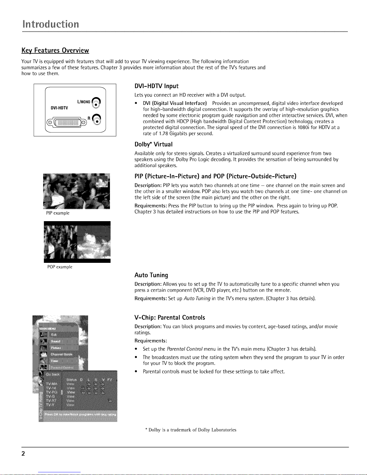
DVI-HDTV Input
Letsyou connect an HD receiver with a DVIoutput.
• DVI{Digital Visual Interface) Providesan uncompressed,digital video interface developed
for high-bandwidth digital connection. It supports the overlay of high-resolution graphics
neededby someelectronic program guide navigation and other interactive services.DVl,when
combined with HDCP[High bandwidth Digital Content Protection) technology, createsa
protected digital connection. Thesignal speedof the DVlconnection is 1080i for HDIVat a
rate of 1.78 Gigabits persecond.
Dolby* Virtual
Available only for stereo signals. Creates a virtualized surround sound experience from two
speakersusing the Dolby Pro Logicdecoding. It provides the sensation of being surrounded by
additional speakers.
PIP (Picture-In-Picture} and POP (Picture-Outside-Picture}
Description: PIP lets you watch two channels at one time - one channel on the main screen and
the other in a smaller window. POPalso lets you watch two channels at one time- one channel on
the left side of the screen (the main picture) and the other on the right.
Requirements: Press the PIP button to bring up the PIP window. Press again to bring up POP.
Chapter 3 has detailed instructions on how to use the PIP and POP features.
Auto Tuning
Description: Allows you to set up the IV to automatically tune to a specific channel when you
press a certain component (VCR,DVDplayer, etc.) button on the remote.
Requirements: Set up Auto Tuning in the Iv's menu system. [Chapter 3 has details).
V-Chip: Parental Controls
Description: You can block programs and movies by content, age-based ratings, and/or movie
ratings.
Requirements:
• Set up the Parental Control menu in the Iv's main menu {Chapter 3 has details).
• The broadcasters must use the rating system when they send the program to your IV in order
for your IV to block the program.
• Parentalcontrols must be locked for thesesettings to take affect.
Dolby is a trademark of Dolby Laboratories
Page 5
Table of Contents
IMPORTANT SAFETY INSTRUCTIONS ....................... 1
Introduction
Key Features Overview ............................................... 2
DVI-HDTV Input ............................................. 2
Dolby* Virtual ................................................... 2
PIP (Picture-In-Picture) and POP
(Picture-Outside-Picture) ................................ 2
Auto Tuning ...................................................... 2
V-Chip: Parental Controls ................................. 2
Chapter 1: Connections and Setup
Things to Consider Before You Connect .................. 4
Protect Against Power Surges .......................... 4
Protect Components from Overheating .......... 4
Position Cables Properly to Avoid Audio
Interference ..................................................... 4
Important Stand and Base Safety
Information ..................................................... 4
Use Indirect Light .............................................. 4
Cables Needed to Connect Components to
Your TV ............................................................ 4
Choose Your Connection ............................................ 5
TV + HD Receiver + VCR + DVD Player .................... 6
TV + Satellite Receiver + VCR .................................. 7
TV + DVD + VCR ......................................................... 8
TV+ AN Receiver or Speakers .................................. 9
Explanation of Jacks ................................................ 10
The Front of Your TV ............................................... 11
Front Inputs ..................................................... 11
Front Panel Buttons ........................................ 11
Plug in the TV ........................................................... 11
Put batteries in the remote ..................................... 11
How to Use the Remote Control to Complete the
Initial Setup .............................................................. 11
Turn on the TV .......................................................... 11
Complete the Initial Setup ...................................... 11
Set the Menu Language ................................. 12
Complete Auto Channel Search ..................... 12
Changing Lists and Labels .............................. 12
Auto Convergence .......................................... 12
Chapter 2: Using the Remote Control
The Buttons on the Remote Control ...................... 13
Using the INPUT Button ................................. 14
Programming the Remote to Operate Other
Components ............................................................ 14
Find Out If You Need to Program the
Remote .......................................................... 14
Programming the Remote .............................. 14
How to Use the Remote After You've
Programmed It .............................................. 15
Remote Control Codes ............................................. 15
Chapter 3: Using the TV's Features
Channel Banner ........................................................ 17
Why You Should Use the Autotuning Feature ...... 17
How to Set Up the Autotuning Feature ........ 17
Parental Controls and V-Chip ................................. 18
How V-Chip Works .......................................... 18
V-Chip TV Rating ............................................. 19
Blocking Specific Content Themes ................. 20
Viewing Specific Content Themes .................. 20
V-Chip Movie Rating Limit ............................. 20
V-Chip Unrated Program Block ...................... 21
Lock/Unlock Parental Controls ....................... 21
Front Panel Block ..............................................
PIP (Picture-in-Picture) and POP
(Picture-outside-Picture) Operation ................... 21
PIP and POP Buttons .........................................
Chapter 4: Using the TV's Menu System
Sound Menu .............................................................. 22
Picture Menu ............................................................ 23
Channel Guide Menu ............................................... 23
Time Menu ................................................................ 24
Parental Control Menu ............................................ 24
PIP Menu ................................................................... 24
Setup Menu .............................................................. 24
Chapter 5: Other Information
Troubleshooting ........................................................ 26
Care and Cleaning .................................................... 27
Limited Warranty ..................................................... 28
Accessories ................................................................ 29
3
Page 6
Connections Setup
Things to Consider Before You Connect
Protect Against Power Surges
• Connect all components before you plug any of their power cords into the wall outlet.
• Turn off the TV and/or component before you connect or disconnect any cables.
• Make sure all antennas and cables are properly grounded. Refer to the Important Safety Instructions on page 1.
Protect Components from Overheating
• Don't block ventilation holes on any of the components. Arrange the components so that air can circulate
freely.
• Don't stack components.
• When you place components in a stand, make sure you allow adequate ventilation.
• If you connect an audio receDer or amplifier, place it on the top shelf so the heated air from it won't flow
around other components.
Position Cables Properly to Avoid Audio Interference
• Insert each cable firmly into the designated jack.
• If you place components above the TV, route all cables down the side of the back of the TV instead of straight
down the middle of the TV.
• lfyour antenna uses 300-ohm twin lead cables, do not coil the cables. Also, keep the twin lead cables away
from audio]video cables.
Important Stand and Base Safety Information
Choose the location for your TV carefully. Place the TV on a stand or base that is of adequate size and strength to
prevent the TV from being accidentally tipped over, pushed off, or pulled off. This could cause personal injury and[
or damage the TV. Refer to the Important Safety Instructions on page 1.
Use Indirect Light
Don't place the TV where sunlight or room lighting will be directed toward the screen. Use soft or indirect lighting.
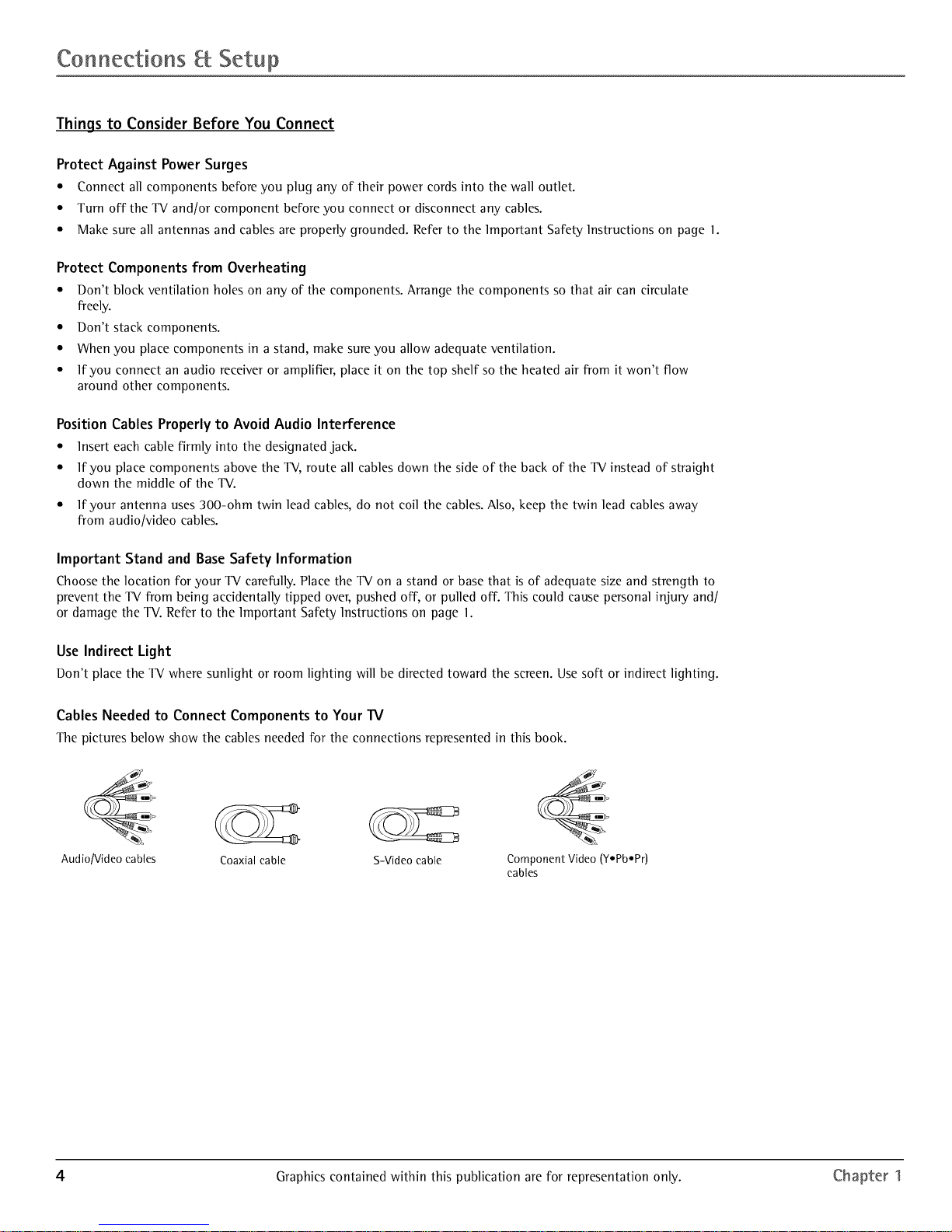
Cables Needed to Connect Components to Your TV
The pictures below show the cables needed for the connections represented in this book.
Audio/Video cables Coaxial cable S-Video cable Component Video (yepbePr)
cables
4 Graphics contained within this publication are for representation only. Chapter 1
Page 7
Connections Setup
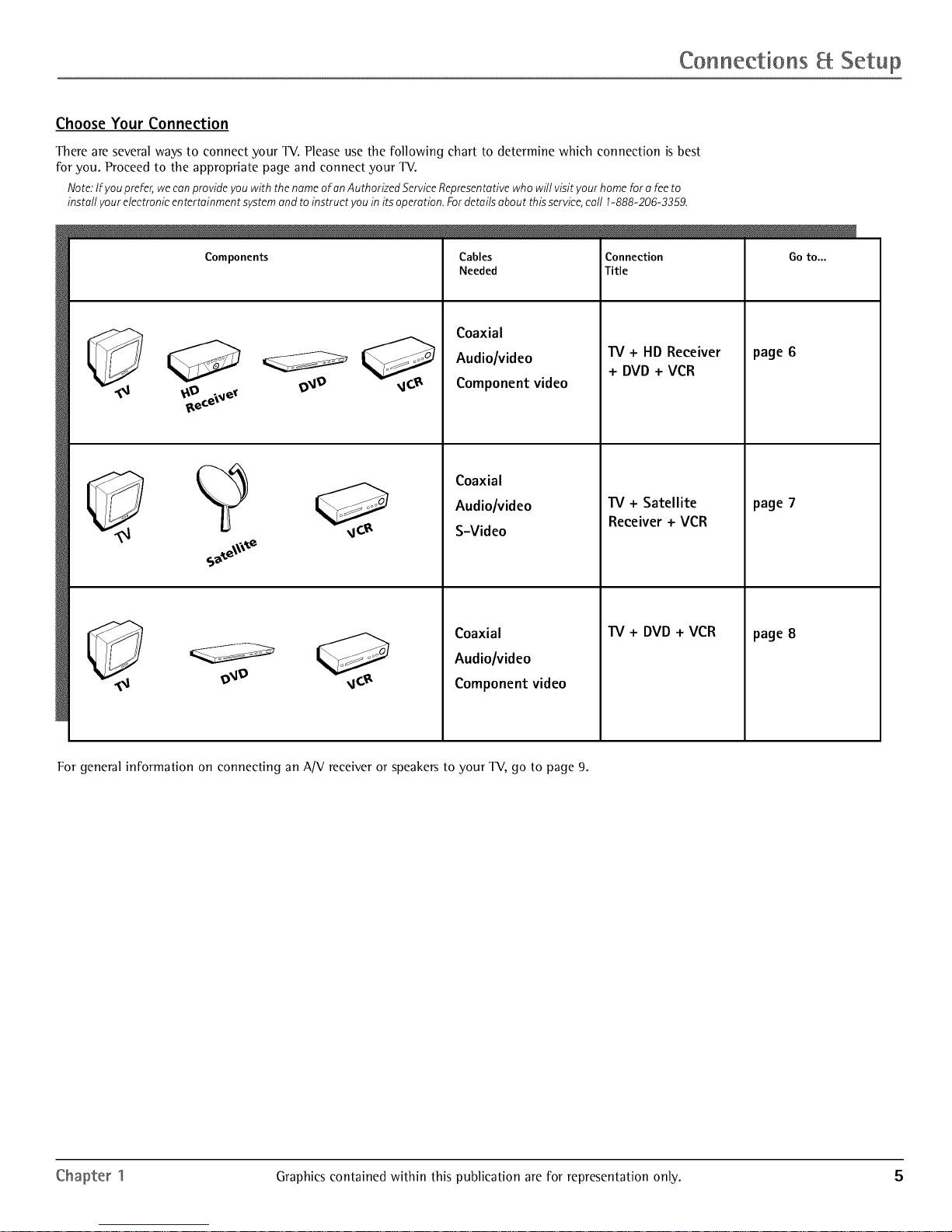
Choose Your Connection
There are several ways to connect your TV. Please use the following chart to determine which connection is best
for you. Proceed to the appropriate page and connect your TV.
Note:If you prefer,wecanprovide you with the nameof an Authorized ServiceRepresentativewho will visit your home for a feeto
install your electronicentertainment systemand toinstruct you in its operation.Fordetails about thisservice,call 1-888-206-3359.
Components
Cables
Needed
Connection
Title
Coaxial
Audio/video
Component video
Coaxial
Audiolvideo
S-Video
TV + HD Receiver
+ DVD + VCR
"IV + Satellite
Receiver + VCR
Coaxial
Audio/video
Component video
"IV + DVD + VCR
Go to...
page 6
page 7
page 8
For general information on connecting an A/V receiver or speakers to your TV, go to page 9.
Chapter 1 Graphics contained within this publication are for representation only. 5
Page 8
Connections Setup
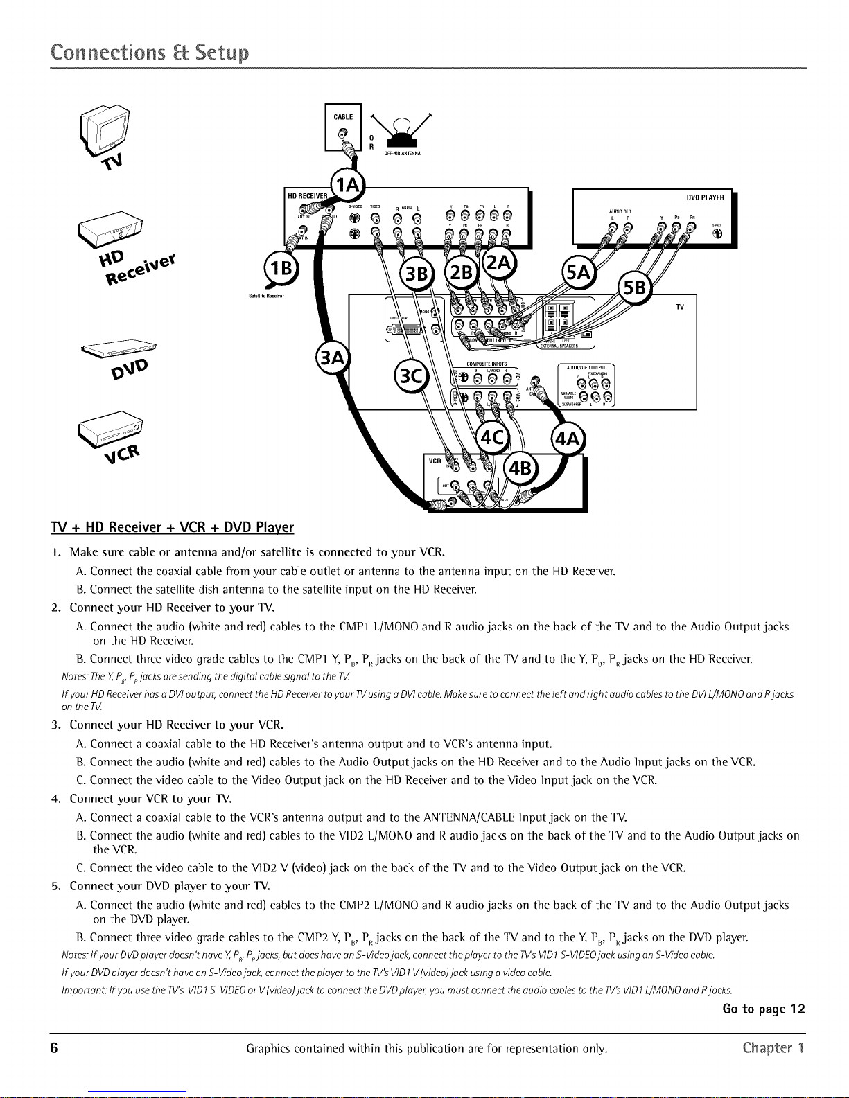
TV + HD Receiver + VCR + DVD Player
I. Make sure cable or antenna and/or satellite is connected to your VCR.
A. Connect the coaxial cable from your cable outlet or antenna to the antenna input on the HD Receiver.
B. Connect the satellite dish antenna to the satellite input on the HD Receiver.
2. Connect your HD Receiver to your TV.
A. Connect the audio [white and red) cables to the CMP 1 L/MON0 and R audio jacks on the back of the TV and to the Audio Output jacks
on the HD Receiver.
B. Connect three video grade cables to the CMP 1 Y, PB, PRjacks on the back of the TV and to the Y, PB, P_ jacks on the HD Receiver.
Notes."TheY,,PB,PnJacksaresending the digital cablesignal to the T_Z
If your HDReceiverhasu DVIoutput, connect theHDReceiverto your TVusing uDVIcable.Makesure to connect theleft and right audio cablesto the DVIL/MONOandRjacks
onthe R4
3. Connect your HD Receiver to your VCR.
A. Connect a coaxial cable to the HD Receiver's antenna output and to VCR's antenna input.
B. Connect the audio [white and red) cables to the Audio Output jacks on the HD Receiver and to the Audio Input jacks on the VCR.
C. Connect the video cable to the Video Output jack on the HD Receiver and to the Video Input jack on the VCR.
4. Connect your VCR to your TV.
A. Connect a coaxial cable to the VCR's antenna output and to the ANTENNA/CABLE Input jack on the TV.
B. Connect the audio [white and red) cables to the VID2 L/MON0 and R audio jacks on the back of the TV and to the Audio Output jacks on
the VCR.
C. Connect the video cable to the VID2 V [video) jack on the back of the TV and to the Video Output jack on the VCR.
5. Connect your DVD player to your TV.
A. Connect the audio [white and red) cables to the CMP2 L/MONO and R audio jacks on the back of" the TV and to the Audio Output jacks
on the DVD player.
B. Connect three video grade cables to the CMP2 Y, PB, P_ jacks on the back of" the TV and to the Y, PB, PR jacks on the DVD player.
Notes."If yourDVDplayer doesn'thave Y,PB,P_jucks, but doeshaveon S-Videojack, connecttheplayer to the TV'sVID1S-VIDEOjack using onS-Videocable.
If your DVDplayerdoesn'thavean S-Videojack,connect the player to the TV'sVID1V(video)juck usingu videocable.
Important: If youusethe TV'sVID1S-VIDEOor V(video)juck to connectthe DVDplayer,youmust connect theaudio cablesto theTV'sVID1L/MONOand Rjacks.
Go to page12
6 Graphics contained within this publication are for representation only. Chapter 1
Page 9
Connections Setup
L
SATELLITE i
RECEIVER
HDTV MONITOR
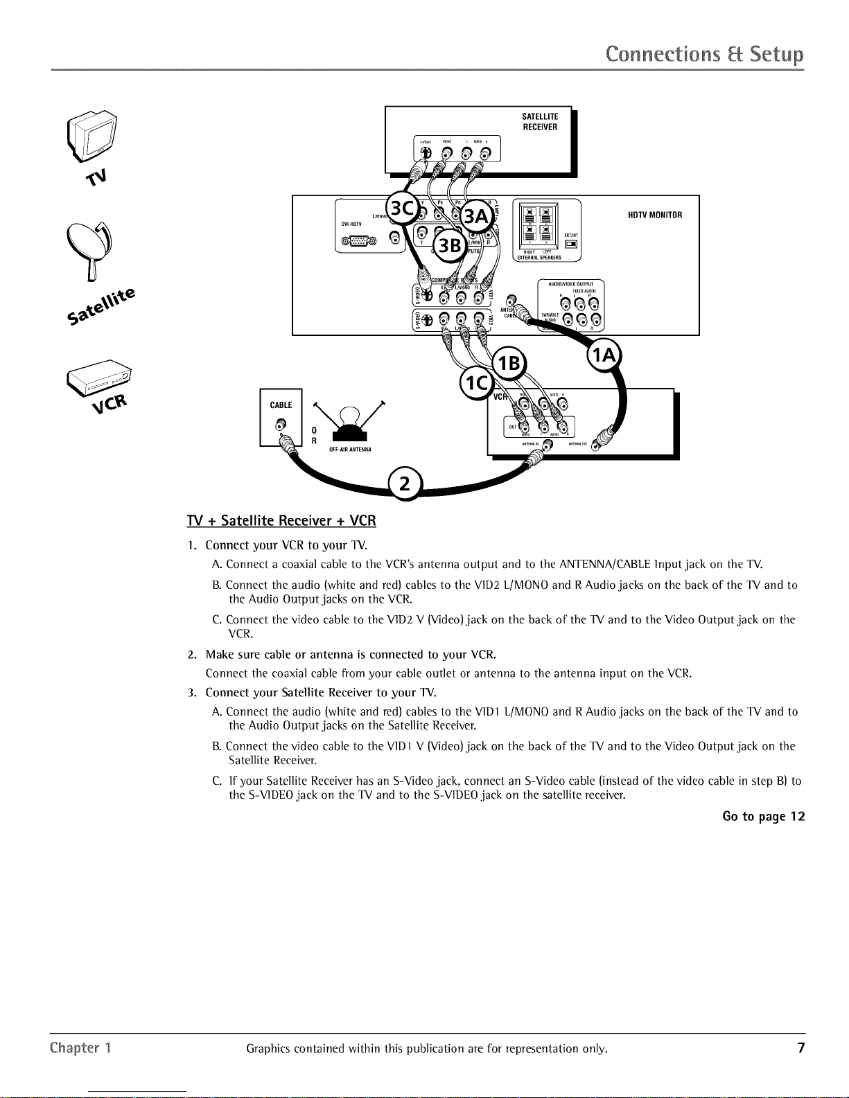
IV + Satellite Receiver + VCR
I,
Connect your VCR to your TV.
A. Connect a coaxial cable to the VCR's antenna output and to the ANTENNA/CABLE Input jack on the TV.
B. Connect the audio (white and red) cables to the V1D2 L[MONO and R Audio jacks on the back of the TV and to
the Audio Output jacks on the VCR.
C. Connect the video cable to the V1D2 V (Video) jack on the back of the TV and to the Video Output jack on the
VCR.
2. Make sure cable or antenna is connected to your VCR.
Connect the coaxial cable from your cable outlet or antenna to the antenna input on the VCR.
3. Connect your Satellite Receiver to your TV.
A. Connect the audio (white and red) cables to the V1D1 L[MONO and R Audio jacks on the back of the TV and to
the Audio Output jacks on the Satellite ReceDer.
B. Connect the video cable to the V1D1V (Video) jack on the back of the TV and to the Video Output jack on the
Satellite Receiver.
C. If your Satellite Receiver has an S-Video jack, connect an S-Video cable (instead of the video cable in step B) to
the S-V1DEOjack on the TV and to the S-VIDEO jack on the satellite receiver.
Go to page12
Chapter 1 Graphics contained within this publication are for representation only. 7
Page 10
Connections Setup
DVD Player
HDTV MONITOR
o
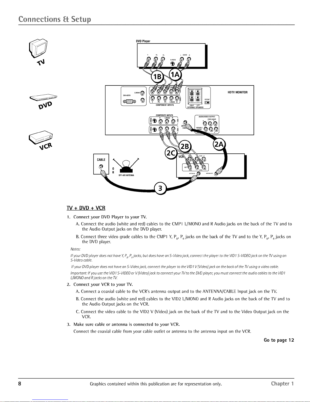
W + DVD + VCR
1. Connect your DVD Player to your TV.
A. Connect the audio {white and red) cables to the CMP1 L/MONO and R Audio jacks on the back of the TV and to
the Audio Output jacks on the DVD player.
B. Connect three video grade cables to the CMP 1Y, PB, PRjacks on the back of the TV and to the Y, PB, PRjacks on
the DVD player.
Notes.
If)lOUtDVDplayer doesnothave Y,,PB,P_jaeks,but doeshaveanS-Videojack, connect theplayer to the VID1S-VIDEOjack onthe TVusingan
S-Videocable.
If )/ourDVDpla)/erdoesnot havean S-Videojack, connectthepla)/erto the VID1V(Video)jaek on the backof the TVusinga videocable.
Important: If )/ouusethe VID1S-VIDEOor V{Video)jaek to connect)/our TVto the DVDpla)/er,)/oumust connect the audio cablesto the VID1
L/MONOandRjacks on the 73/
2. Connect your VCR to your TV.
A. Connect a coaxial cable to the VCR's antenna output and to the ANTENNA/CABLE Input jack on the TV.
B. Connect the audio {white and red) cables to the V1D2 L/MONO and R Audio jacks on the back of the TV and to
the Audio Output jacks on the VCR.
C. Connect the video cable to the V1D2 V {Video) jack on the back of the TV and to the Video Output jack on the
VCR.
3. Make sure cable or antenna is connected to your VCR.
Connect the coaxial cable from your cable outlet or antenna to the antenna input on the VCR.
Go to page12
8 Graphics contained within this publication are for representation only. Chapter 1
Page 11

Connections Setup
TV+ A/V Receiver or Speakers
These are two different ways your TV uses a component to hear audio.
I. Connect audio cables to either the F]XED or VAR]ABLE AUD]O L and R OUTPUT jacks and to the Audio ]nputs
on the A/V receiver.
• F]XED provides fixed-]evel audio output from the TV. This audio output is ideal for connecting to an
A/V receiver that has its own volume control.
• VAR]ABLE provides variable-]evel audio output. Volume levels can be controlled by the volume
controls on the TV and TV remote control.
-OR-
2. Use speaker wire to connect the TV to external speakers.
• The EXT/]NT switch beside the jacks let you turn the TV's internal speakers on or off. ]f you connect
external speakers, slide the switch to EXT so the audio is sent to the external speakers only.
Choosing ]NT sends the audio to the TV's speakers only.
Note:Theexternalspeakerrating is8 ohms with 15watts power handling capabilities.
AN RECEIVER
V_ _RIABLEOutput
< w._ABte
Connect to either FIXED or
TV
Chapter 1 Graphics contained within this publication are for representation only. 9
Page 12

Connections Setup
Explanation of Jacks
This section describes the jacks you can use to make connections. There are several ways to connect components
to your TV.
F L/MONO_1
DVI-HDTV
R
Ioo ooo
PB PB L/rvlONOR )
COMPONENTINPUTS
COMPOSITEINPUTS
(° 99
V L/MOI,IOR J
I UDIO/VIDEOOUTPUT
FIXEDAUDIO /
VARIABLE _ _ r%l
AUDIO
SUBWOOFER L R J
f
RIGHT LEFT
,..EXTERNALSPEAKERS
EXTANT
J
DV1-HDTV Input Lets you connect an HD receDer with a DVI output.
• DVI (Digital Visual Interface) Provides an uncompressed, digital video interface developed
for high-bandwidth digital connection. It supports the overlay of high-resolution graphics
needed by some electronic program guide navigation and other interactive services. DV1,
when combined with HDCP (High bandwidth Digital Content Protection) technology, creates
a protected digital connection. The signal speed of the DVI connection is 1080i for HDTV at a
rate of 1.78 Gigabits per second.
• L/MONO (Audio) Provides left audio connection when using the DVI jack. The left audio
connector is usually white.
• R (Audio) Provides right audio connection when using the DVI jack. The right audio
connector is usually red.
Note:Rememberto connect theleft andright audio cablesbecausetheDVIcablecarriesonly the picturesignal,
not the sound.
COMPONENT INPUTS Lets you connect a component video source, such as a DVD player.
• CMPI Y, PB, PR (Component Video) Provides optimum picture quality because the video is
separated into three signals. Use three video-grade cables for the connection. When using
CMP1 Y, PB, PR,make sure to connect left and right audio cables to the CMP1 L/MON0 and R
Audio Input jacks.
• CMP] L/MON0 (Audio) Provides left audio connection. The left audio connector is usually
white.
• CMPI R (Audio) Provides right audio connection. The right audio connector is usually red.
• CMP2 Y, PB, P_, and L/MONO and R Audio Allows you to connect a second component
video source. Their description is the same as CMP1 above. When using CMP2 Y, PB, PR' make
sure you connect the left and right audio cables to the CMP2 Audio jacks.
COMPOSITE 1NPUTS Lets you connect another component such as a VCR, DVD player, or
laserdisc player. Its AUDIO jacks are the same as described for CMP1 above.
• V1D1 S-VIDEO Provides better picture quality than the video jacks (VID1 and 2 Video)
because the color part of the signal is separated from the black and white part of the picture.
When using V1D1 S-VIDEO, make sure to connect left and right audio cables to the VID1 L/
MONO and R Audio Input jacks.
• V1D1 V (Video) Provides composite video connection. The video connector is usually yellow.
• V1D2 S-VIDEO, V and L/MONO and R Audio Allows you to connect a component such as
a VCR, DVD player, or laserdisc player. Their description is the same as VID 1 above.
Note:Donot connect an S-Videoand Videocableat the sametime in either VID1or VlD2jacks.
AUD10/V1DE0 OUTPUTS Lets you connect an amplifier or audio receiver for improved sound
quality or an external video monitor.
• FIXED AUDIO L/R Provides fixed-level audio output from the TV. This audio output is ideal
for connecting to an A/V receiver when you want to control the volume through the A/V
receiver.
• VARIABLE AUDIO Provides variable-level audio output. Volume levels are controlled by the
volume controls on the TV and remote control.
• SUBW00FER Provides lower bass audio frequencies out from the TV and to a subwoofer.
Note:If you'veconnecteda subwoofer,makesureyou set theExternalSubwoofer option in theSoundmenu. Goto
page22 for instructions.
EXTERNAL SPEAKERS
• Right and Left Speaker Terminals Let you connect external left and right speakers to the
TV to receive left and right sound.
• EXT/INT (switch) Lets you turn the TV's internal speakers on or off. EXT sends audio to
external speakers only. INT sends audio to the TV's internal speakers only.
ANTENNA/CABLE Lets you connect a coaxial cable to receive the signal from the antenna,
cable, cable box, or if using the examples on pages 6-8, a VCR.
10 Graphics contained within this publication are for representation only. Chapter 1
Page 13

Connections Setup
The Front of Your TV
Front Inputs
The TV has front inputs for convenience: one set of audio/video inputs, an S-Video and a headphone jack. Locate the jacks either
on the front of the IX/or on one of the sides. You can access the component you connected to the front of the IX/by pressing the
INPUT button on your remote until FRNT appears on the screen. The jacks are ideal for using a video game console or a
camcorder.
Note:Whenconnecting adevicethat usesamonaural cable,such assomecamcorders,usethe Left(mona) inputjack to get soundfrom bothspeakers.
PHONES Allows you to connect headphones to listen to the sound coming from the TV. To adjust volume control of the
headphones, press the VOL > or VOL < button (the volume display appears). Press the arrow up or down button (the headphone
volume display appears), then press the right or left arrow button to adjust the headphone volume.
VIDEO (in) ReceDes video from another component such as a VCR, camcorder or video game console.
L]MONO and R AUDIO ReceDes audio from another component such as a VCR, camcorder or video game console.
S-VIDEO (in) Allows you to connect an S-Video cable from another component. Make sure you also connect audio cables from
the component to the TV.
Front Panel Buttons
If you cannot locate your remote, you can use the front panel buttons of your TV to operate many of the TV's features.
MENU/OK Brings up the Main menu. In the menu system, it selects highlighted items.
CH v Scans down through the current channel list. In the menu system, acts like down arrow button on the remote control and
adjusts menu controls.
CH n Scans up through the channel list. In the menu system, acts like up arrow button on the remote control and adjusts menu
controls.
VOL < Decreases the volume. In the menu system, acts like left arrow button on the remote control and adjusts menu controls.
VOL > Increases the volume. In the menu system, acts like right arrow button on the remote control and adjusts menu controls.
POWER Turns the TV on and off.
Plug in the TV
Plug the end of the power cord into a grounded wall outlet. Insert the plug completely into the outlet.
Put batteries in the remote
• Remove the battery compartment cover from the back of the remote by pushing down on and
sliding off the cover.
• Insert 2 "AA" fresh batteries. Make sure the polarities (+ and -) are aligned correctly.
• Replace the cover.
TV button
Arrows
Tip
Toaccess the setup menus manually, press
MENUand choose SETUP.
How to Usethe Remote Control to Complete the Initial Setup
The technical term is "Navigation" - how you move through the on-screen menus. The theory is
the same throughout the menu screens: highlight your choice and select it.
To highlight a menu item, press the arrow buttons on the remote to highlight one of the items
listed on the screen. Use the up or down arrow button to move up or down. Use the right or left
arrow button to move right or left.
To select the item that you've highlighted, press OK.
Note:Highlighted means that the menuitem stands out from other menu items onthe list (appearsdarker,brighter,
or adifferent color).
Turn on the TV
Press TV on the remote, or press POWER on the TV's front panel.
Note:Pressingthe TVbutton not only turns onthe TV,butputs the remote into TVmode."TVmode"means that the
buttons on the remotecontrol operatethe TV'sfunctions.
Complete the Initial Setup
The menu system in your TV allows the TV's features to work properly. The first time you turn on
your TV, the setup screens appear.
Chapter 1 Graphics contained within this publication are for representation only. 11
Page 14

Connections Setup
Set the Menu Language
The first part of the setup allows you to select your preferred language for the menu system.
1. Highlight your preferred language for the menu system using the arrow buttons.
2. Press OK to select that language (the Channel Setup screen appears with Auto channel
search highlighted).
Complete Auto Channel Search
This part of the setup allows the TV to search for all channels viewable through your antenna
or cable TV system. This is sometimes called auto programming. Press OK to begin auto
channel search. When the channel search is complete, press OK to access the List _ Labels
screen.
Changing Lists and Labels
The List Et Labels part of the setup lets you edit your channel list and choose or create a
personal six-character label for each channel.
Note:ChangingList andLat_elscant_etime consuming.Youcan changetheseata later timet_yaccessingthe
Setupmenu.
1. Press the left or right arrow to scroll through the available channels and choose the
channel you want to edit.
2. Press the clown arrow to highlight the In channellist option. Press the left or right arrow
button to add (the box is checked) or remove (the box is unchecked) the channel from the
list.
3. Press the clown arrow to highlight the Channel label option. Press the left or right arrow
button to scroll through the available list of 25 most common labels. The last option in
the list allows you to create your own six-character label for the channel (the first letter of
the label is highlighted).
4. Press the 1 or 2 number button to change the first letter of the label.
5. Press the right arrow to highlight the second letter, then press the 1 or 2 number button
to change the second letter, etc...
6. When you are finished creating your label, highlight 60 Back (the Auto Convergence menu
appears).
Auto Convergence
Your TV's picture tubes might have been disturbed during delivery or after you moved the TV,
causing the color in your TV to be out of alignment. The colors adjust by starting auto
convergence.
1. Press OK to begin auto convergence.
2. When the auto convergence is complete, the Red center convergence menu appears. The
cross in the middle of the screen should be yellow. If it is not, use the arrow buttons to
move the red cross to overlap the green cross. Press OK when adjustments are complete.
3. The Blue eentereonvergenee menu appears with a cyan cross in the middle of the screen. If
it is not, use the arrow buttons to move the blue cross to overlap the green cross. Press OK
(the TV tunes to the last available channel in the channel list).
12 Graphics contained within this publication are for representation only. Chapter 1
Page 15

Using the Remote Control
Indicator
J
VCRI ON-OFF TV
DVD VCR2 AUX SAT, CABLE
/V_U I k SKIP
GUIDE O GO BACK
DISC MENU INFO
MENU CLEAR
40
70
INPUT SOUND,ANT
©
REVERSE PLAY FORWARD
RECORD STOP PAUSE
PiP SWAP CH - CH ÷
©©©©
L.-- plp...-I
Note. TheVCR1,DVD,VCR2,and SAT, CABLEbuttons
also turn on most RCA,GE,and Proscan products.
/
Tip
Toturn off all the RCA, GE, and Proscan components that
are connected to the 1_, press ONoOFF twice within two
seconds.
Thisfeature only works with most RCA,GE,andProscan
products.
The Buttons on the Remote Control
(O-9) Number Buttons Enter channel numbers and time settings directly through the remote
control.
To enter a one-digit channel, enter a zero first. To enter a two-digit channel, press the two digits.
To enter a three-digit channel, press and hold the "1" button until "1" and two dashes (i _)
appear, then add the second two digits. Example: to tune to channel 123, press and hold 1 until
"1- -" appears, release the 1 button and then press 2 and 3.
Arrows Used to point to different items in the IV menu and to adjust the menu controls.
Moves the PIP window when no menus are on the screen. Also switches the two POP windows
when no menus are on the screen. For Zoom use, go to next page.
AUX Puts the remote in AUX mode. Can also be programmed to operate most brands of an
additional remote-controllable component.
Baeklight Lights up some of the buttons in the dark.
CH+orCH- Scans up or down through the current channel list. Press once to change the
channel up or down; press and hold to continue changing channels.
CH+ or CH- PIP When using PIP or POP,changes the channel in the picture window.
CLEAR Removes any menu or display from the screen and returns you to normal viewing.
DISC MENU No function available in IV mode. If operating an RCA, a GE or Proscan DVD player,
for example, brings up the Disc menu.
DVD Puts the remote in DVD mode and, if Autotuning is enabled, will turn on the IV and tune to
the correct input channel.
FREEZE When watching IV, freezes the picture until you press another button to resume
normal IV viewing.
Note:Donot usetheFreezefeature for an extendedperiod of time. Thiscancausethe imageto bepermanently
imprinted onthe picture tube.Suchdamageis notcoveredbyyour warranty Pressany button to unfreezethe
picture at any time.
60 BACK Returns you to the previous channel.
6UIDE Brings up the Channel Guide menu.
INDICATOR Indicates the programming mode when programming the remote to control
components.
INFO Brings up status display; press again to clear the screen.
INPUT Pressto toggle through the available input sources (VlD1, VlD2, FRNT,CMP1, CMP2 and
DVl. Press the CH+ or CH- button to resume IV viewing).
MENU Brings up the Main menu.
MUTE Reduces the Iv's volume to its minimum level. Press again to restore the volume.
OK/FREEZE When in the menu system, selects highlighted items. When watching IV, freezes
the picture until you press another button to resume normal IV viewing.
ON.OFF When in IV mode, turns the IV on and off. If in another device mode (VCR, DVD,
SAT-CABLE, etc.) and programmed, will turn the device on and off.
PIP Press once to bring up the small picture-in-picture window. Pressagain to bring up the
picture-outside-picture (POP)windows. Press to remove POR (See Chapter 3 for more
information about using PIR)
REVERSE, PLAY, FORWARD, RECORD, STOP, PAUSE If programmed, provides transport control
for some remote-controllable VCRs, DVD players, laserdisc players, tape decks, and CD players.
SAT.CABLE Puts the remote in SAT-CABLE mode and, if Autotuning is enabled, will turn on
the IV and tune to the correct input channel.
SKIP Press once before changing channels and the IV will wait 30 seconds before returning
you to the original channel. Press repeatedly to add more time.
SOUND.ANT Displays the Picture and Sound preset settings at the bottom of the IV.
SWAP When using PIP, swaps the main picture with the PIP window. When using POP,swaps
the left and right pictures.
TV Turns on the IV and puts the remote in IV mode. Also displays current status.
Chapter 2 Graphics contained within this publication are for representation only. 13
Page 16

Usin s the Remote Control
VCR1 Puts the remote inVCR1 mode and, ifAutotuningisenabled, will turn on the TV and tune to the correct
input channel.
VCR2 Puts the remote in VCR2 mode and, ifAutotuning is enabled, will turn on the TV and tune to the correct
input channel.
VOL - or VOL + Decreases or increases the TV'svolume.
ZOOM+ or ZOOM- When watching TV, changes the current format of the screen (4x3, Zoom 14/9, Zoom 16/9,
Zoom 16/9 ^Iv, Cinerama, regular mode 16/9).
Using the INPUT Button
Use the INPUT button to scroll through the available input channels and view components you have connected to
the TV.
1. Press TV to place the remote in TV mode. Make sure the component you want to view is turned ON.
2. Press INPUT to tune to an available input channel.
3. To return to the channel you were previously watching on TV, press CH+ or CH- button.
_
VCR1 ON * OFF TV
DVD VCR2 AUX SAT*CABLE
REVERSE PLAY
STOP
You'll use these buttons when you program
the remote.
Important. The remote may not be compatible with all
models of all brands of components. It also may not
operate all functions of the remote that came with
your component.
Tip
Tostop the automatic code search without programming
any components, press and hold CLEARuntil the indicator
on the remote turns off
Proqramminq the Remote to Operate Other Components
The universal remote can be programmed to operate most brands of remote controllable
components. The remote is already programmed to operate most RCA, GE,and Proscan
components.
Also, the AUX button can be programmed to operate most brands of an additional remote-
controllable component.
Note:TheR/button can't beprogrammedon this remote.
Find Out If You Need to Program the Remote
To determine whether the universal remote needs to be programmed for your component, turn
the component ON. For example, to program the remote for a VCR, turn on the VCR. Point the
remote at theVCR, and press theVCR1 button. Then press ON*OFF or CH + [channel up) or CH -
[channel down) to see if the VCR responds to the remote commands. If the component does not
respond, the remote needs to be programmed.
Programming the Remote
There are two ways to program the remote control:
• automatic code search
• direct entry
Using Automatic Code Search
The following instructions can be used to program the remote to operate each of your
components. If you want to stop the automatic code search without programming any of your
components, press CLEAR until the indicator on the remote turns off.
1. Turn on the component you want to operate [VCR, DVD player, etc.)
2. Press and hold the component button you want to program [VCR1, DVD, etc.). While holding
the component button, press and hold ON•OFF until the indicator on the remote turns on,
then release both buttons.
3. Point the remote at the component. Press and release PLAY, then wait 5 seconds or until the
indicator on the remote stops flashing.
At this point the remote is searching for the correct code to program. If, after 5 seconds, the
component you want to operate does not turn off, press PLAY again to tell the remote to
search the next set of codes.
Continue pressing PLAY until the component turns off or you have searched through all of
the codes. There are 20 total sets of codes. If the component does not turn off after pressing
PLAY 20 times, then the remote can't be programmed to operate that component.
If the component you want to control does turn off:
1. Press and release REVERSE,then wait 2 seconds. Repeat this step until the device turns back
ON.
2. To finish, press and hold STOP until the indicator on the remote turns off.
14 Graphics contained within this publication are for representation only. Chapter 2
Page 17

Using the Remote Control
Important
You must continue pressing the component button while
you enter the code.
Let's say you have a Zenith VCR. To program the universal
remote to operate the VCR, you would:
Press and hold the VCR1 button while you enter the first
code listed for Zenith in the VCR Codes column.
Release the VCR1 button. Press ON*OFF to see if the VCR
responds. If it doesn't, follow the same steps, but enter the
second code for Zenith VCRs instead of the first.
Note
Some of the remote 'sbuttons might operate differently for
other components, especially when you're using another
component's menu system.
Using Direct Entry
1. Turn on the component to be programmed.
2. Look up the brand and code number(s) for the component on the code list in this section.
3. Point the remote at the component.
4. Press and hold the component button you want to program on the remote.
5. Enter the 4-digit code from the remote control code list on the following pages. If the
indicator flashes, you have either entered an invalid code or the button isn't programmable.
6. Release the component button, and then press ON-OFF to see if the component responds to
the command. If it doesn't, try pressing the component button and then ON-OFF again.
• If you get no response, repeat these steps using the next code listed for your brand, until the
component responds to the remote commands.
• If you try all the codes for your component brand and none work, try the automatic code
search method. If automatic code search doesn't find the code, the remote is not compatible
with your component.
How to Use the Remote After You've Programmed It
Because this universal remote can control several different components (IV, DVD, VCR, satellite
receiver, etc.) it uses operational modes triggered by the component buttons. For example, if you
want the remote to control the TV, you would press the TV button to put the remote into IV
mode before you could control the TV.
I. Press the appropriate component button (DVD, TV, VCRI, VCR2, SAT-CABLE, AUX) to set the
remote to control the component.
2. Press ON-OFF to turn the component ON or OFF.
3. Use the remote buttons that apply to that component.
Notes.
• The remote may no t be compatible with all brands and models of components. It also may not
operate all functions of the remote that came with your eomponent.
• If you keep pressing buttons and nothing happens, the remote is probably in the wrong mode. You
must press the component button that matches the component you want to operate (i.e., if you want
to operate the VCR, press VCR 1 on the remote control to put the remote in VCR mode.)
Remote Control Codes
VCR Codes
Programmable for VCR1, VCR2, and AUX
buttons.
Admiral .............................................................................. 2132
Adventura .......................................................................... 2026
Aiko .................................................................................... 2027
Aiwa ................................................................................... 2026
Akai ........... 2003, 2004, 2005, 2007, 2008, 2111, 2112, 2113
American High .................................................................. 2021
Asha ................................................................................... 2013
Audio Dynamics .................................................... 2009, 2010
Audiovox ........................................................................... 2014
Bell It Howell ..................................................................... 2011
Beaumark ........................................................................... 2013
Broksonic ................................................................ 2012, 2025
Calix ................................................................................... 2014
Candle ............................................... 2013, 2014, 2015, 2016,
....................................................................... 2017, 2018, 2019
Canon ............................................................ 2021, 2022, 2114
Capehart ................................................................... 2020, 2110
Carver ................................................................................. 2062
CCE .......................................................................... 2027, 2061
Citizen .................................................................... 2013, 2014,
....................................... 2015, 2016, 2017, 2018, 2019, 2027
Colortyme .......................................................................... 2009
Colt ..................................................................................... 2061
Craig ................................................... 2013, 2014, 2023, 2061
Curtis-Mathes ............................................. 2000, 2009, 2013,
............................. 2016, 2018, 2021, 2022, 2024, 2115, 2131
Cybernex ........................................................................... 2013
Daewoo ...... 2015, 2017, 2019, 2025, 2026, 2027, 2028, 2110 Kodak ................................................................. 2014, 2021
Daytron ................................................................................. 2110 Lloyd ............................................................................ 2026
DBX ............................................................................ 2009, 2010 Logik ............................................................................ 2061
Dimensia .................................................................... 2000, 2131 LXI ................................................................................ 2014
Dynatech .............................................................................. 2026 Magnavox ............................................. 2021, 2022, 2062,
Electrohome ............................................................. 2014, 2029 ............................................ 2063, 2104, 2105, 2108, 2124
Electrophonic ...................................................................... 2014
Emerson ......................... 2012, 2014, 2015, 2021, 2024, 2025,
.......... 2026, 2029, 2030, 2031, 2032, 2033, 2034,2035,
2036,. ......... 2037, 2038, 2039, 2040, 2041, 2042,2044,
2045, 2046,. ........................................... 2047, 2065, 2113,
2116, 2117, 2130
Fisher ......... 2011, 2023, 2048, 2049, 2050, 2051, 2052, 2118
Fuji ............................................................................. 2021, 2119
Funai .................................................................................... 2026
Garrard ................................................................................. 2026
GE ................................................................... 2000, 2001, 2013,
......................................... 2021, 2022, 2053, 2115, 2120, 2131
Goldstar ............................................... 2009, 2014, 2018, 2054
Gradiente ............................................................................. 2026
Harley Davidson ................................................................. 2026
Harman Kardon .................................................................. 2009
Harwood .............................................................................. 2061
Headquarter .......................................................................... 2011
Hitachi ..................................................................... 2055, 2056,
Magnin ......................................................................... 2013
Marantz ........ 2009, 2010, 2011, 2016, 2018, 2021, 2062,
2064
Marta ............................................................................ 2014
Masushita .................................................................... 2021
Mei ............................................................................... 2021
Memorex ...... 2011, 2013, 2014, 2021, 2023, 2026, 2104,
2132
MGA ........................................................ 2029, 2065, 2113
MGN Technology ........................................................ 2013
Midland ........................................................................ 2053
Minolta ................................................... 2055, 2056, 2107
Mitsubishi .. 2029, 2055, 2056, 2065, 2066, 2067, 2068,
• 2068, 2070, 2071, 2072, 2073, 2074, 2106, 2113, 2123
Montgomery Ward ........................................... 2075, 2132
Motorola ............................................................ 2021, 2132
MTC .................................................................... 2013, 2126
Multitech ........................... 2013, 2016, 2026, 2053, 2061
NEC ...................................... 2009, 2010, 2011,2016, 2018,
..................................................... 2057, 2107, 2111, 2120, 2122 .................................. 2064, 2076, 2078, 2079, 2111, 2123
Hi-Q ...................................................................................... 2023
Instant Replay ..................................................................... 2021
JCL ......................................................................................... 2021
JC Penney ............................................ 2009, 2010, 2011, 2013,
.................................................. 2014, 2021, 2022, 2055, 2056,
.................................................... 2058, 2059, 2060, 2107, 2118
Jensen ............................................................. 2055, 2056, 2111
JVC ................................... 2009, 2010, 2011, 2018, 2111, 2123
Kenwood ................ 2009, 2010, 2011, 2016, 2018, 2111, 2123
KLH ....................................................................................... 2061
Nikko ............................................................................ 2o14
Noblex .......................................................................... 2013
Olympus ....................................................................... 2021
0ptimus .............................................................. 2014, 2132
0ptonica ...................................................................... 2096
Panasonic ............... 2021, 2022, 2109, 2125, 2126, 2127
Pentax ................................ 2016, 2055, 2056, 2107, 2120
Pentex Research .......................................................... 2018
Philco ........................................... 2021, 2022, 2062, 2063
Philips .......................................... 2021, 2062, 2096, 2124
Chapter 2 Graphics contained within this publication are for representation only. 15
Page 18

Using the Remote Control
VCR Codes continued
Pilot ............................................................................. 2014
Pioneer ............................. 2010, 2055, 2080, 2081, 2123
Portland ....................................... 2016, 2017, 2019, 2110
Prosean .................................................. 2000, 2001, 2131
Protec .......................................................................... 2061
Pulsar .......................................................................... 2104
Quarter ........................................................................ 2Oll
Quartz ......................................................................... 2Oll
Quasar ................................................... 2o21, 2022, 2125
RCA ........... 2000, 2001, 2003, 2013, 2021, 2055, 2056,
....... 2082, 2083, 2084, 2085, 2086, 2087, 2088, 2089,
............ 2090, 2091, 2107, 2115, 2120, 2125, 2131, 2133
Radioshaek/Realistic ................. 2011, 2013, 2014, 2021,
......... 2022, 2023, 2026, 2029, 2049, 2050, 2096, 2132
Radix ........................................................................... 2014
Randex ........................................................................ 2014
Rieoh ........................................................................... 2128
Runeo .......................................................................... 2104
Samsung ................ 2005, 2013, 2015, 2033, 2053, 2112
Sanky ................................................................ 2104, 2132
Sansui .......................................... 2010, 2092, 2111, 2123
Sanyo ..................................................... 2011, 2013, 2023
Scott. 2012, 2015, 2025, 2032, 2038, 2065, 2093, 2116
Sears ................................. 2011, 2014, 2021, 2023, 2048,
.................... 2049, 2050, 2051, 2055, 2056, 2107, 2118
Sharp .......... 2017, 2029, 2094, 2095, 2096, 2097, 2132
Shintom ..................................... 2004, 2056, 2061, 2098
Shogun ........................................................................ 2013
Signature .................................................................... 2132
Singer ..................................................... 2021, 2061, 2128
Sony ............................................ 2004, 2098, 2099, 2119
STS .................................................................... 2021, 2107
Sylvania ..... 2021, 2022, 2026, 2062, 2063, 2065, 2124
Symphonic ................................................................. 2026
Tandy .......................................................................... 2011
Tashiko ........................................................................ 2014
Tatung .......................................................................... 2111
TEAC ...................................................... 2026, 2085, 2111
Technics ............................................................ 2021, 2109
Teknika ............................. 2014, 2021, 2026, 2100, 2129
TMK ....................................................... 2013, 2024, 2047
Toshiba ........ 2015, 2049, 2051, 2055, 2065, 2093, 2116
Totevsion ......................................................... 2013, 2014
Unitech ........................................................................ 2013
Vector Research ......................... 2009, 2010, 2015, 2016
Victor .......................................................................... 2010
Video Concepts ................ 2009, 2010, 2015, 2016, 2113
Videosonic .................................................................. 2013
Wards ......................................... 2013, 2014, 2015, 2021,
............................. 2023, 2026, 2029, 2055, 2056, 2061,
...................... 2096, 2101, 2102, 2103, 2107, 2116, 2132
XR-IO00 ............................................... 2021, 2026, 2061
Yamaha .............................. 2009, 2010, 2011, 2018, 2111
Zenith ................................ 2004, 2098, 2104, 2119, 2128
Satellite Receiver Codes
Programmable for SAT CABLE and AUX
buttons.
Alphastar .................................................................... 5079
Chapparal ........................................................ 5056, 5057
Dishnet ........................................................................ 5078
Drake ................................................................ 5058, 5059
Echostar ...................................................................... 5089
GE ..................................................................... 5000, 5001
General Instruments ............................ 5060, 5061, 5062
Hitachi ............................................................. 5083, 5084
Hughes ............................................................. 5077, 5090
JVC .............................................................................. 5082
Panasonic ................................................................... 5075
Philips ......................................................................... 5085
Primestar ....................................................................5076
Proscan ............................................................ 5000, 5001
RCA .................................. 5000, 5001, 5071, 5080, 5081
Realistic ...................................................................... 5063
Sony ............................................................................ 5072
STS1 ............................................................................ 5064
STS2 ............................................................................ 5065
STS3 ............................................................................ 5066
STS4 ............................................................................ 5067
Toshiba ............................................................. 5068, 5073
Uniden ............................................................. 5069, 5086
Cable Box Codes
Programmablefor SAT•CABLEandAUXbuttons.
ABC ........................................... 5002, 5003, 5004, 5006, 5053
Antronix ................................................................... 5008, 5009
Archer ............................................................. 5008, 5009, 5010
Cabletenna ........................................................................... 5008
Cableview ............................................................................ 5008
Colour Voice .............................................................. 5012, 5013
Comtronics .......................................................................... 5014
Contec .................................................................................. 5016
Eastern ................................................................................. 5017
GC Electronics ..................................................................... 5009
GE .............................................................................. 5000, 5001
Gemini ....................................................................... 5018, 5019
General Instrument ............................................................ 5003
Hamlin ........................... 5020, 5021, 5022, 5028, 5035, 5045
Hitachi ................................................................................. 5003
Jerrold ............................ 5003, 5018, 5023, 5024, 5046, 5053
Magnavox ........................................................................... 5025
Memorex .............................................................................. 5026
Movie Time ......................................................................... 5027
NEC ....................................................................................... 5005
NSC ....................................................................................... 5027
Oak ............................................................................ 5016, 5029
Panasonic ................................................................ 5048, 5052
Philips ........................................ 5011, 5012, 5013,5015, 5019,
..................................................... 5025, 5030, 5031, 5032
Pioneer ...................................................................... 5033, 5034
Proscan ..................................................................... 5000, 5001
RCA ...................................................... 5007, 5047, 5049, 5052
Realistic ............................................................................... 5009
Regal ......................................................................... 5022, 5035
Regency ............................................................................... 5017
Rembrandt ........................................................................... 5003
Samsung .............................................................................. 5034
Scientific Atlanta ............................... 5006, 5036, 5037, 5038
Signal ................................................................................... 5018
Signature ............................................................................. 5003
Sprucer ................................................................................. 5052
Standard Components ............................................. 5039, 5044
Starcom ..................................................................... 5018, 5053
Stargate ................................................................................ 5018
Starquest .............................................................................. 5018
Tocom ....................................................................... 5004, 5023
Tusa ...................................................................................... 5018
TV86 ..................................................................................... 5027
Unika ......................................................................... 5008, 5009
United Cable ........................................................................ 5053
Universal ......................................................... 5008, 5009, 5010
Viewstar .................................................................... 5025, 5027
Zenith ........................................................................ 5050, 5051
DVDcodes
Programmable for DVD and AUX buttons.
Aiwa ..................................................................................... 3009
GE ......................................................................................... 3000
Hitachi ................................................................................. 3008
JVC ............................................................................. 3002, 3010
Konka ......................................................................... 3011, 3012
Magnavox ........................................................................... 3003
Mitsubishi ............................................................................ 3004
Panasonic ............................................................................ 3013
Philips .................................................. 3003, 3019, 3021, 3022
Pioneer ................................................................................. 3005
Proscan ................................................................................ 3000
RCA ........................................................................... 3000, 3001
Sanyo ................................................................................... 3014
Sony ................................................................ 3006, 3015, 3016
Toshiba ............................................................ 3007, 3017, 3020
Zenith ................................................................................... 3018
Audio Codes
Programmablefor the AUX button only.
RCA and Dimensia
AM/FM .......................................................... 4003, 4270
AUX .......................................................................... 4004
Phono ....................................................................... 4005
Tape ........................................................................... 4006
CD ......................................................... 4007, 4190, 4211
Receivers
Aiwa ............................................ 4261, 4262, 4263, 4264,
....................................................... 4265, 4266, 4267, 4277
Denon ............................................................................. 4283
Harman Kardon ............................................................ 4276
JVC ................................................................................. 4268
JVL ................................................................................. 4276
Kenwood ........................................................................ 4269
0nkyo ............................................................................. 4278
0ptimus .......................................................................... 4284
Panasonic ........................................................... 4279, 4280
Pioneer ........................................................................... 4275
RCA ................................................................................ 4270
Sherwood ....................................................................... 4282
Sony .......................................................... 4271, 4272, 4281
Technics .............................................................. 4279, 4280
Wards ............................................................................. 4275
Yamaha ............................................................... 4274, 4275
CD Players
ADC .......................................................... 4200, 4201, 4220
Aiwa .................................................................... 4175, 4203
Akai ................................................................................ 4205
Denon ............................................................................. 4208
Dynatech ........................................................................ 4177
Emerson ......................................................................... 4178
Fisher ........................................................ 4179, 4212, 4213
GE ................................................................................... 4216
Hitachi ........................................................................... 4180
JVC ....................................................................... 4181, 4221
Kenwood .................................................. 4183, 4222, 4224
Luxman .......................................................................... 4225
Marantz ............................................................... 4185, 4226
Mitsubishi ........................................................... 4229, 4230
MCS ................................................................................ 4228
Nakamichi .......................................................... 4232, 4233
NEC ................................................................................. 4184
0nkyo ....................................................... 4186, 4234, 4235
0ptimus .................................................... 4237, 4238, 4239
Panasonic ...................................................................... 4188
Pioneer ................................................................ 4189, 4240
RCA ...................................................................... 4190, 4211
Sanyo ............................................................................. 4250
Sears ............................................................................... 4207
Sherwood ....................................................................... 4243
Sony ......................................................... 4195, 4209, 4244
Teac .......................................................... 4245, 4246, 4247
Technics ......................................................................... 4197
Toshiba ........................................................................... 4231
Yamaha .................................................... 4198, 4199, 4248
16 Graphics contained within this publication are for representation only. Chapter 2
Page 19

Sample displays on a Channel Banner.
Usin9 the W% Features
Channel Banner
There are several indicators that might appear when you press the TV or INFO buttons on the
remote. This display is called the Channel Banner. The following list describes the items on the
Channel Banner screen {left to right and top to bottom).
4/3 format
Mono
(or Stereo)
SAP
CC
03:45pm
15N BC
Commercial
skip0:30
Displays the current screen format.
Mono displayed when the current channel is broadcasting in mono.
Stereo displayed when the current channel is broadcasting in stereo.
Displayed when the current channel is broadcasting SAP {Second Audio
Program) information.
Displayed when the Parental Controls are locked.
Displayed when Closed Captioning is available on the current channel.
Displays the current time.
Displays the current channel and label assigned to the channel.
Displayed to count time remaining on the commercial skip {SKIP) timer.
Displayed when you mute the sound.
With the autotuning feature, you can set up the TV
to tune to the channel you need to watch by
pressing that eomponent's button.
Why You Should Use the Autotuning Feature
The autotuning feature automatically tunes the TV to the correct channel for different
components you have connected to your TV {like a VCR, DVD Player, etc.) When you set up
autotuning in the menu system you don't have to remember to change your TVto channel 3, for
example, when you want to watch the tape in your VCR.
How to Set Up the Autotuning Feature
The way you set up the autotuning feature in the TV's menu corresponds to the component
buttons on the remote and the way you have each component connected to your TV.When you
set up autotuning, you're telling the TV what channel to tune to when you press the VCR1, VCR2,
DVD, or SAToCABLE button on the remote control.
1.
2.
3.
4.
Press MENU (the MAIN MENU appears).
Highlight Setup and press OK on your remote control.
Highlight Autotuning and press OK.
Choose which channel you would like to set:
Set VCR 1 Channel Lets you set up the channel the TV tunes to when you press the VCR1 button.
Set VCR 2 Channel Lets you set up the channel the TV tunes to when you press the VCR2 button.
Set DVD Channel Lets you set up the channel the TV tunes to when you press the DVD button.
Set SAT/Cable Channel Lets you set up the channel the TV tunes to when you press the SAToCABLE button on
an RCA satellite receiver remote. [The RCA DTCIO0 HD receiver is considered a satellite device and can be set up
for autotuning using this channel.)
Press the right arrow button to select the choice that matches the way you have the component connected to
this TV, and press OK.
The choices and a brief explanation follow:
N/A Choose this if you don't have this particular component connected to the TV, or if you don't
want the TV to automatically tune to the correct channel when you're using this component.
Channel3 or4 Component is connected to the CABLE/ANTENNA jack on the back of the TV, and
you want the TV to tune to channel 3 when you press the corresponding button on the remote.
Reminder: make sure the component's Channel 3/4 switch is set to channel 3.
VID1 or VID2 (Video Input) Component is connected to a VIDEO or S-Video jack on the back of
the TVand you want the TV to tune to a VlD input channel when you press the corresponding
button.
FRNT(Front Video Input) Component is connected to the VIDEO jack on the front of the TV and
you want the TV to tune to the front VlD input channel [FRNT) when you press the corresponding
button.
Chapter 3 Graphics contained within this publication are for representation only. 17
Page 20

Usin9 the W% Features
CMP1 or CMP2 (Component Video Input) Compatible component video source, such as a DVD player or digital 11/converter box, is
connected to the three COMPONENT VIDEO INPUT jacks (Y,PB,PR) on the back of the 11/and you want the TV to tune to the component
video input channel {CMP) when you press the corresponding button.
DVI Component is connected to the DVI-HDCP jack on the back of the 11/and you want the 11/to tune to the DVI input channel when
you press the corresponding button.
Parental Controls and V-Chip
The first three choices in the Parental Controls menu involve software inside your TV {referred to as V-Chip) which allows you to block
TV programs and movies based on violence, sex, or other content you may believe children should not view.
Once you block programs, you can unblock programs by entering a password.
By default, the software inside your TV is turned "off."
Note:ParentalControl settings are not available for DVI,CMP1or CMP2inputs.
How V-Chip Works
V-Chip reads the program's age-based rating {TV-MA, TV-14, etc.) and content themes [(Violence {V), Adult Language {L), etc.)]. If you
have blocked the rating and/or content themes that the program contains, you will receive the message This channel is not approved for
viewing.
Broadcasters are not required to provide content themes, so programs received with no content themes will only be blocked if you
block their age-based rating. You can also block out programs that have been given a rating of "Not Rated," and programs that are
considered "unrated." The TV age-based ratings and content themes you can block are listed in the following table.
Age-Based Rating
TV-MA
TV-14
TV-PG
Description and Content Themes for Age-Based Ratings
Mature Audience Only. Specifically designed to be viewed by adults and may be unsuitable for children under 17. It contains
one or more of the following content themes: crude indecent language {L), explicit sexual activity {S), or graphic violence {V).
Parents Strongly Cautioned. Contains some material that many parents would find unsuitable for children under 14. Parents
are strongly urged to exercise greater care in monitoring this program and are cautioned against letting children under the
age of 14 watch unattended. This program contains one or more of the following content themes: intensely suggestive
dialogue {D), strong coarse language {L),intense sexual situations {S), or intense violence {V).
Parental Guidance Suggested. Contains material that parents may find unsuitable for younger children. Many parents may
want to watch it with their younger children. The program contains one or more of the following content themes: some
suggestive dialogue {D), infrequent coarse language {L), some sexual situations {S), or moderate violence {V).
TV-G General Audience. Most parents would find this program suitable for all ages. It contains little or no sexual dialogue {D) or
situations {S), no strong language {L), and little or no violence {V).
Directed to Children 7 years and older. Designed for children ages 7 and above. It may be more appropriate for children who
TV-Y7 have acquired the developmental skills needed to distinguish between make-believe and reality. Themes and elements in this
program may include mild fantasy violence {FV)or comedic violence, or may frighten children under the age of 7.
All Children. Themes and elements in this program are designed for a young audience, including children from ages 2-6. It is
TV-Y
not expected to frighten younger children.
18 Graphics contained within this publication are for representation only. Chapter 3
Page 21

Usin 9 the W% Features
V-Chip W Rating
The V-Chip TVRating lets you decide which TV programs can and cannot be viewed.
To set TV programming limits:
1. Choose Parental Control from the Main menu. If Parental Controls have previously been locked,
you must enter your password.
2. Press OK to continue.
3. Highlight and select V-Chip TV rating.
4. Once you get to the V-Chip TVrating limitscreen, use the arrow buttons and OK on your
remote to change the status of a TV program rating or content theme from View to Block.
5. For TV rating limits to take effect, lock Parental Controls by accessing the Loekparental
controls menu.
The following sections give you more details about how to change the status of TV program
limits.
TheV-Chip RatingScreen
Thefollowing isan example of where items are located within the Rating Limit screen.
Rating Status Field
Lets you select whether the status of the age-based rating limit to the
left is View or Block.
Rating Field
Lets you select from a list
of age-based ratings you
can block or view.
Content Themes
Lists the content themes you
can block or view.
Content Status Fields
Lets you select which content
themes to view for the selected
rating, and whether the status of
the content theme is currently
View (_ or Block (_).
Rating Settings Area
Letsyou see the current bloek/view state of age-based ratings and associated
content. The View (_ settings are coded in green, and the Block (_) settings
are coded in red.
Chapter 3 Graphics contained within this publication are for representation only. 19
Page 22

Usin9 the W's Features
Hierarchy of Age-Based Ratings
IV-MA Mature Audience Only
71/- 14 Parents Strongly Cautioned
IV-PC Parental Guidance Suggested
IV-G General Audience
IV-Y7 Directed to Children 7 years and older
IV- Y All Children
Content Themes
D Sexually explicit dialogue
L Adult language
S Sexual situations
V Violence
FV Fantasy Violence
Tip
Tochangeall V-Chip movie or Iv ratings to View,press
the0 number button.
Blocking Age-Based Ratings
You can automatically block all program ratings above a specified age-based rating level.
To block programs with higher ratings:
1. Press the up or down arrow button to scroll to the rating corresponding with the lowest
rating you do not want the child to watch.
2. Press the OK button to toggle between Viewand Block. The status for the rating listed to the
left and all higher ratings automatically changes to Block {and _.
3. Press the up or down arrow button to highlight Go back and press OK.
4. Select Lock Parental Controls from the Parental Control menu for rating limits to take effect.
Viewing Age-Based Ratings
After you block age-based ratings, you can change some of the ratings back to View.
1. Press the up or down arrow button to select the rating with a status of Block.
2. Press OK to select View.
Blocking Specific Content Themes
You can block programs based on their content. (Content is represented by the D, L,S, V and FV
on your screen.) When you block a content theme for a particular rating, you automatically
block that content theme for higher rated programs as well.
To block program content:
1. Determine the content themesyou want to block.
2. Press the down arrow button to scroll to the rating whose content theme you want to
change.
3. Press the right arrow button to move the yellow highlight to a particular content theme
status.
4. Press the OK button to change its status to ,_. {In the example to the left, you block the
language {L) corresponding with TV-14. The language for TV-MA is blocked as well.)
Notes.Broadcastersarenot required toprovide content themesor age-basedratings.
Youmust remembertolockParental Controlsfor rating limits totake effeeL
Viewing Specific Content Themes
If you block specific content themes, you have the option of going back and changing some of
the content themes back to _ View:
1. Determine the content themes you want to change to _ View.
2. Press the down arrow button to scroll to the rating whose content theme you want to
change, such as _ under language {L)corresponding with TV-14.
3. Press the right arrow button to move the yellow highlight to a particular content theme
status.
4. Press the OK button to change the status back to _.Your child would then be able to watch
programs with the TV-14 adult language content, but not programs with TV-MA language
content.
Note: Onlythe content themestatus correspondingto IV- 14 (L)language changesto (V)View.Higherrated
content themes,such asthat for IV-MA language,do not change.
V-Chip Movie Rating Limit
Set movie rating limits by blocking movies rated above a specified level.
To change menu:
1. Press MENU on the remote control (the TVMAIN MENU appears).
2. Select Parental ControL
3. Select V-Chip movie rating.
20 Graphics contained within this publication are for representation only. Chapter 3
Page 23

Usin9 the W's Features
Blocking Movie Ratings
Onceyou are in the Movie Ratings menu, follow the same stepsdescribed for blocking TVratings.
V-Chip Unrated Program Block
This option lets you decide if programs that the V-Chip recognizes as "unrated" can be viewed. "Unrated" TV programs
may include news, sports, political, religious, local and weather programs, emergency bulletins, public announcements,
and programs without ratings.
View All unrated programs are available.
Block All unrated programs are not available.
Note.Youmust rememberto lock ParentalControls for rating limits to takeeffect.
Pressthe down arrow to highlight V-Chip unrated. Then press the right arrow to switch between Block and View.
Lock/Unlock Parental Controls
Selecting this option lets you lock and unlock parental controls settings using a password.
If you do not lock parental controls, none of the settings for V-Chip, Channel Block, or Front
Panel Block will take effect.
If you forget your password, press the MENU button, then select Parental Control (the password
entry screen appears). Simultaneously press and hold CH+ and VOL+ on the television for 3
seconds. Parental Controls unlock and the Parental Control menu appears so you can enter a new
password.
Front Panel Block
Selecting this option lets you block {disable) or unbloek {enable) the TV'sfront panel. The remote
still tunes to any channel. When using this as a Parental Control method, remove aecess to any
remote that is capable of operating the television while you have the front panel blocked.
Don't forget to lock parental controls after you change the status. If you don't, the front panel
block will not take effect.
PIP (Picture-in-Picture] and POP (Picture-outside-Picture] Operation
The PIP (picture-in-picture) feature lets you display a second, smaller picture on top of the main
picture. POP (picture-outside-picture) lets you display two windows side by side.
Note."PIPand POParenotavailable for DVIor component videosources(CMP1orCMP2).
0;:t'.uO.....
o_o
,0 _0 _0
_0 _0 00
_Q_o:_,
0°0 0
<_ [3:>D
Arrow
buttons
PIP buttons
PIP example
POP example
PIPand POP Buttons
There are several remote buttons that control the way the PIP window works:
PIP Brings up the PIP window. Press again to bring up POP. Press again to remove the window.
Up and down arrow buttons Let you move the PIP window to different corners of the screen.
Up arrow moves PIP counterclockwise; down arrow moves PIP clockwise.
Left and right arrow buttons Switches the left POPwindow to the right side, and the right
POPwindow to the left.
SWAP Switches, or "swaps," the video from the PIP window with the main picture. Switches the
main POP window, where the sound is coming from, with the other window.
PIP CH+ and CH- Lets you change channels in the PIP and right POP picture.
Chapter 3 Graphics contained within this publication are for representation only. 21
Page 24

Using the W's Menu System
Sound Menu
Sound settings Displays a choice list that lets you adjust the TV's speakers and subwoofer.
Left _ Right balance Use the left or right arrow to center the bar under the arrow to
balance the left and right speakers.
Left _ Right speakers Use the left or right arrow to select External [if your TV is using
external amplifier) or Internal [if your TV is using the speakers in the TV).
Subwoofer Set the TV's subwoofer to External, if the TV is using an external subwoofer; or
None.
Sound type Press the right arrow to scroll through the available audio types, which control the
way the sound comes through your speakers.
Mono Plays the sound in mono only. Use this setting when receiving broadcasts with weak
stereo signals.
Stereo Splits the incoming stereo audio signal into left and right channels. Most TV
programs and recorded materials have stereo audio. The word Stereo appears on the TV
when you tune to a program that is broadcast in stereo.
Automatic Chooses the sound type according to the current signal.
Sound Mode Press the right arrow to scroll through the available audio modes, which provides
special processing through your speakers and depends on how you set the sound type.
Normal Does not give any special processing, simply provides mono or stereo sound.
Wide Available only for mono signals. "Widens" sound from mono broadcasts and mono
components connected to your TV for a fuller, more spacious sound.
Magic Available only for stereo signals. Gives a surround effect with more bass.
Dolby Virtual Available only for stereo signals. Creates a virtualized surround sound
experience from two speakers using the Dolby Pro Logic decoding. It provides the sensation
of being surrounded by additional speakers.
Surround effect Controls the amount of surround sound in Dolby Virtual sound mode.
SeeondAudio Program (SAP) Plays the program's audio in a second language, if one is available.
The TV displays the word SAP when you tune to a program that is broadcast with SAP
information. SAP audio is broadcast in mono. SAP is also used to broadcast a program's audio
with descriptions of the video for the visually impaired.
Automatic sound level Reduces the annoying blasts in volume during commercial breaks, and
also amplifies softer sounds in program material. Eliminates the need to constantly adjust
volume control.
Headphone settings Displays a choice list of available settings you can adjust: Volume, Bassand
Treble. The Headphone sound option allows you to choose stereo, mono or automatic. These
descriptions are same as sound type above.
Graphic equalizer Allows you to choose a specific sound through the Sound Preset option. Press
the right arrow to cycle through the options: Standard, Movie, Voice, Music, Flat, Videogame,
Video camera and PersonaL
The Frequeneyrange displays the different treble and bass bands set for each Sound Preset
option. You can choose a band and make adjustments. When you make adjustments, the Sound
Preset option automatically changes to Personal. Pressthe left or right arrow button to select the
frequency [Bass lOOHz, Mid Bass 500Hz, Medium 1.5kHz, Mid Treble 5kHz, Treble lOkHz) you
want to adjust. Then use the up or down arrow button to adjust the decibel.
To view the frequency range of another Sound Preset option, press the right arrow until no
band is selected and Frequency range is highlighted. Then press the up arrow to highlight
Sound Preset.
22 Graphics contained within this publication are for representation only. Chapter 4
Page 25

Using the W's Menu System
Picture Menu
The Picture menu options apply to the video for the main TV and video input selections.
Advanced picture settings
Contrast expand Adjusts the contrast of the picture according to the light of the room.
Press the right arrow to choose between Low, Medium or High.
SVM (Scan Velocity Modulation) Improves the sharpness of the picture by changing the
speed of the cathode-ray tube's electron beam when it transitions between dark and light
areas of the screen. Choose to have it on (box checked) or off (box unchecked), depending on
your preference.
Autoformat When enabled (box checked) the TV automatically detects the screen format
the signal is sending for each channel, as well as input channels.
Video noise reduction Allows you to choose a setting to reduce picture "static" or any type
of interference. It is especially useful for providing a clearer picture in weak analog signal
conditions. Press the right arrow to choose between: Offfor no noise reduction; Minimum
for a softer, smoother picture and retains picture sharpness and detail; Medium for a slightly
softer picture than the Minimum setting; Maximum for an even softer, smoother picture
than the other settings. However, the picture detail is somewhat decreased.
Note:Autoformat and Videonoisereduction are availablefor DVI,CMP1andCMP2inputs if the
signal is480L
Picture Presets Displays a choice list that lets you select one of the preset picture settings:
Mode, Videogame, Personal, Sports, Ideal, Showroom or Video Camera. Choose the setting that is
best for your viewing environment.
Black Level Adjusts the brightness of the picture.
Color Adjusts the richness of the color.
Contrast Adjusts the difference between the light and dark areas of the picture.
Sharpness Adjusts the crispness of the edges in the picture.
Note:Youcan adjust sharpnessfor eachchannel.Thisisuseful if channelsappear fuzzy.
Color Warmth Displays a choice list that lets you set one of three automatic color adjustments:
Coolfor a more blue palette of picture colors; Normal; and Warm for a more red palette of
picture colors. The warm setting corresponds to the NTSCstandard of 6500 K.
Tint Adjusts the balance between the red and green levels.
Note:Tint not available for DVI,CMP1andCMP2inputs.
When you change any of these picture settings, the Picture Preset changes to personal. Use the
left or right arrow button to make adjustments. To return to the Picture menu, press the up or
down arrow button.
Channel Guide Menu
Allows you to view and select from the entire channel list and their labels. Press the GUIDE
button to bring up the Channel Guide menu. Use the up or down arrow to scroll through the list.
PressOK to select and tune to the chosen channel.
Chapter 4 Graphics contained within this publication are for representation only. 23
Page 26

Using the W's Menu System
Time Menu
Sleep timer Lets you set the TV to turn off after a given time.
time Lets you enter the current time. If it is eight o'clock, for example, you must first enter the
number zero, then number eight. Use the OK button to choose between AM and PM.
Wake up timer Lets you set the TV to turn itself on. When you turn on Wake up timer, the
following options appear:
Wake up time Lets you set the time you want the TV to turn itself on.
Wake up duration Lets you set how long you want the TV to stay on when it turns on.
Channelnumber Lets you select a specific channel the TV tunes to when the wake up timer
is set.
Daily Lets you choose if you want the wake up timer to turn on daily.
Parental Control Menu
The Parental Control Menu was explained in Chapter 3. Go to page 18 for more information.
PIP Menu
Display Mode
OFF No window is displayed.
PIP PIP (single) window is displayed.
POP POP (double) window is displayed.
PIPchannel Allows you to choose the channel displayed in the PIP or main POP window. Scroll
through channel list as well as the VlD1, VlD2 and FRNTinput channels.
PIPsize Allows you to choose having a Small, Medium or Large PIP window.
PIPposition Allows you to choose having the PIP window in the Top right, Topleft, Bottom right
or Bottom left part of TV.
Note:Pipsizeand position arenot available for POR
Setup Menu
Channel setup
Signal Type TV chooses signal type during initial setup. If you change cable after setup,
choose Cable if you are using cable or a cable box for TV signals. Choose UHFNHF Antenna if
you are using an off-air antenna for TV signals.
Auto channel search Searches for channels the signal is receiving. Go to page 12 for more
information.
Auto channel update Searches for any new channels that are not in your channel list and
adds them to the list.
List and labels Edit the channels in the list or choose labels for each channel. Go to page 12
for more information.
Preferences
Language Displays a choice list that lets you select your preferred language for the menus:
English, Spanish or French.
Maximum volume Allows you to set how high volume turns up when you press the VOL+
button. Highlight Maximum volume, then press and hold OK to hear is the maximum
volume. Make sure the volume has not been muted or turned all the way down.
Curtain effect Reveals or hides the picture by giving it a "stage curtain" effect when the TV
is switched on or off.
Special features Auto on switches you r TV on after a power outage; Auto channel tunes the
TVto the channel you specify as the Initial channel when Auto on is enabled; Auto volume
tunes the TV to the volume you set in Initial volume when Auto on is enabled.
24 Graphics contained within this publication are for representation only. Chapter 4
Page 27

Usin 9 the W's Menu System
Closed Caption Many programs are encoded with closed-captioning information, which lets you
display the audio portion of a program as text on the TV screen.
Closed captioning is not available on all channels at all times. Only specific programs encoded
with closed-captioning information are applicable. When a program is closed captioned, CC is
displayed in the channel banner. See Chapter 3 for more information about the channel banner.
The closed caption options are:
Closed caption setting Displays a choice list that lets you choose the way closed captioning
information is shown on the screen. Closed-captioning is not available with the high
resolution input.
Off No captioning information displayed.
On always Captioning information shown always, when available.
On when mute Displays captioning information, when available, whenever the TV's
sound is muted by pressing the MUTE button. The captioning information is not
displayed when the sound is not muted.
Closed-Caption Mode Displays a choice list that lets you choose which captioning mode is
used for displaying captioning information. If you are unsure of the differences among the
modes, you may prefer to leave the closed captioned mode set to CC1, which displays
complete text of the program in the primary language in your area.
Autotuning Displays a choice list that lets you set up the TV to automatically tune to the
correct input channel when you press a component button [VCR1, DVD, VCR2, SAToCABLE, etc.)
on the remote. (30 to Chapter 3 for details about the Autotuning feature.
Convergence Auto convergence automatically adjusts the TV'stubes; Red convergence displays
the Red convergence screen, allowing you to use the arrow buttons to align the red and green
images; Blue convergence displays the Blue convergence screen, allowing you to use the arrow
buttons to align the blue and green images.
Chapter 4 Graphics contained within this publication are for representation only. 25
Page 28

Other mnformation
Troubleshooting
Most problems you encounter with your TV can be corrected by consulting the following troubleshooting list.
Note:If you prefer,wecanprovide you with the nameof an Authorized ServiceRepresentativewho will visit your home for a feeto install your electronicentertainment system
andto instruct you in its operation.Fordetails about this service,call 1-888-206-3359.
TV Problems
I"V won't turn on
• Pressthe IV button.
• Make sure the IV is plugged in.
• Check the wall receptacle (or extension cord) to make sure it is "live" by plugging in something else.
• Something might be wrong with you r remote control. Pressthe POWERbutton on the front of the IV. If the IV turns on, check the remote control
solutions on page 27.
• The front panel controls may be locked (disabled). Use the remote control to unlock the front panel controls by selecting the Front Panel Block in the
Parental Control menu and press OK to uncheck the box.
Buttons don't work
• If you're using the remote control, press the IV button first to make sure the remote is in IV mode.
• The front panel controls may be locked (disabled). Use the remote control to unlock the front panel controls by selecting the Front Panel Block in the
Parental Control menu and press OK to uncheck the box.
• Unplug the IV for two minutes and then plug it back in. Turn the IV on and try again.
TV turns off while playing
• Sleep timer may have been activated. Go to page 24 for instructions.
• Electronic protection circuit may have been activated because of a power surge. Wait 30 seconds and then turn on again. If this happens frequently, the
voltage in your house may be abnormally high or low.
• Unplug. Wait five minutes. Plug in again.
TV turns on unexpectedly
• Wake up timer might have been activated. Go to page 24 for instructions.
• Auto on might have been activated. Go to page 24 for instructions.
• You might have pressed CH+, CH- or INPUT on the remote accidentally.
Blank screen
• Make sure the component connected to the IV is turned on.
• Try another channel.
No sound,pictureokay
• Maybe the sound is muted. Try pressing the volume up button to restore sound.
• If using S-Video or Y, PB,P,, remember to also connect the component's left and right audio output jacks to the Iv's L/MONO and R Audio Input jacks.
• Make sure the INT/EXTswitch on the back of the IV is put on "INT".
• The sound settings may not be set correctly. Go to page 22 for more information.
Can't select certain channel
• Channel may be blocked or not approved in the Parental Controls menu.
• If using a VCR, check to make sure the IV/VCR button on the VCR is in the correct mode (press the IV/VCR button on your VCR).
Noisy stereo reception
• May be a weak station. Use Sound menu to choose mona sound.
No picture/blue screen, no sound but TV is on
• Maybe the cable/air function isset to the wrong position. Go to page 24 for detailed instructions.
• The channel might be blank- change channels.
• If you're watching your VCR and it's connected with coaxial cable to the CABLE/ANTENNAjack, tune the IV to channel 3 or 4 (whichever channel is
selected on the 3/4 switch on the back of your VCR).Also check to make sure the IVNCR button on the VCR is in the correct mode (press the IV/VCR
button on your VCR).
26 Graphics contained within this publication are for representation only. Chapter 5
Page 29

Other +nformat+on
Sound okay, picture poor
• Check antenna connections. Make sure all of the cables are firmly connected to the jacks.
• Try adjusting sharpness function to improve weak signals. Go to page 23 for more instructions.
Volume buttons not adjusting volume louder
• Checkto makesurevolumeisn't limited by the maximumvolume feature. Goto page24 for more instructions.
Picture not moving
• Youhaveactivatedthe Freezefeature by pressingOKon the remote.Pressany button to "unfreeze"the picture.
Black box appears on the screen
• Closed-captioningmight beon. CheckClosedCaptionin the Setupmenu.Goto page25for more instructions.
Freeze not working
• Thefreezefeature is not availablefor Componentvideo (CMP1or CMP2)or DVIinputs.
Low battery warning appears on screen
• Placenew batteriesin remote.
The Remote Control Doesn't Work
• Something might be between the remote and the remote sensor on the component. Make sure there is a clear path.
• Maybe the remote isn't aimed directly at the component (TV or VCR}that you're trying to operate.
• Maybe remote is not in TV Mode. Pressthe TVbutton so remote will control TV.
• Maybe batteries in remote are weak, dead, or installed incorrectly. Put new batteries in the remote. (Note, if you remove the batteries, you may have to
reprogram the remote to operate other components.)
• You might need to drain the remote's microprocessor: remove batteries and press the number 1 button for at least 60 seconds. Releasethe 1 button,
replace the batteries, and (if necessary) program the remote again.
Problems with V-Chip/Parental Controls
The rating limits don't work
• Youmust lockthe settings.Goto the MAINMENU(pressMENUon your remote),selectParental Control,selectLock ParentalControls.
I don't remember my password and I want to unlock the TV
• If you forget your password, press MENU, then select Parental Control (the password entry screen appears). Simultaneously pressand hold CH+ and VOL+
on the TV's front panel for 3 seconds. The Parental control menu appears on the screen, and you can re-enter a password via Lock Parental Controls.
The V-Chip won't let me watch a program even though it's not rated as violent.
• Maybe the movie was given an NR (Not Rated) status. After you block movie ratings, you must set NR to View separately in order to view movies with an
NR rating.
Care and Cleaning
CAUTION: Turn OFFyour TV before cleaning.
You can clean the TV as required, using a soft lint-free cloth. Be sure to occasionally dust the ventilation slots in the cabinet to help assure adequate
ventilation.
The TV's screen may be cleaned with a soft, lint-free cloth as well. Take care not to scratch or mar the screen. If necessary, you may use a cloth
dampened with warm water. Never use strong cleaning agents, such as ammonia-based cleaners, or abrasive powder. These types of cleaners will
damage the TV.
While cleaning do not spray liquid directly on the screen, or allow liquid to run down the screen and inside the TV.Also, never place drinks or vases
with water on top of the TV. This could increase the risk of fire or shock hazard or damage to the TV.
Caution: Using video games or any external accessory with fixed images for extended periods of time can cause them to be permanently imprinted on
the picture tube (or projection TV picture tubes). ALSO,some network/program Iogos, phone numbers, etc. may cause similar damage. This damage is
not covered by your warranty.
Chapter 5 Graphics contained within this publication are for representation only. 27
Page 30

Other mnformation
Limited Warranty
What your warranty covers:
• Defects in materials or workmanship.
For how long after your purchase:
• One year from date of purchase for labor.
• One year from date of purchase for parts.
• Two years from date of purchase for the picture tube.
The warranty period for rental units begins with the first rental or 45 days from date of shipment to the rental firm, whichever comes first.
What we will do:
• Pay an Authorized Service Center the labor charges to repair your unit.
• Pay an Authorized Service Center for the new, or at our option, refurbished replacement parts and picture tube required to repair your unit.
How you get service:
• Call 1-866-SCENIUM and have your unit's date of purchase and model number ready.
• A representative will troubleshoot your problem over the phone.
• If the representative determines that you should receive service, they will provide you with the name(s) of the Authorized Service Center in your
area.
• Contact the Service Center and arrange for home or pick up, repair, and return service, provided that your unit is located within the geographic
territory covered by an Authorized Service Center. If not, you must take your unit to the Service Center location at your own expense, or pay for
the cost the Service Center may charge to transport your unit to and from your home.
• Proof of purchase in the form of a bill of sale or receipted invoice which is evidence that the product is within the warranty period must be
presented to obtain warranty service. For rental firms, proof of first rental is also required.
What your warranty does not cover:
• Customer instruction. (Your Owner's Manual describes how to install, adjust, and operate your unit. Any additional information should be
obtained from your dealer.)
• Installation and related adjustments.
• Signal reception problems not caused by your unit.
• Damage from misuse or neglect.
• Batteries.
• Damage from images burnt onto the screen.
• A unit that has been modified or incorporated into other products.
• A unit purchased or serviced outside the U.S.A.
• Acts of nature, such as but not limited to lightning damage.
Product registration:
• Please complete and mail the Product Registration Card packed with your unit. It will make it easier to contact you should it ever be necessary.
The return of the card is not required for warranty coverage.
Limitation of Warranty:
• THE WARRANTY STATEDABOVE IS THE ONLY WARRANTY APPLICABLE TO THIS PRODUCT. ALL OTHER WARRANTIES, EXPRESS OR IMPLIED
(INCLUDING ALL IMPLIED WARRANTIES OF MERCHANTABILITY OR FITNESS FOR A PARTICULAR PURPOSE) ARE HEREBY DISCLAIMED. NO
VERBAL OR WRITTEN INFORMATION GIVEN BY THOMSON MULTIMEDIA INC., ITS AGENTS OR EMPLOYEES SHALL CREATE A GUARANTY OR IN
ANY WAY INCREASE THE SCOPE OF THIS WARRANTY.
• REPAIR OR REPLACEMENT AS PROVIDED UNDER THIS WARRANTY IS THE EXCLUSIVE REMEDY OF THE CONSUMER. THOMSON MULTIMEDIA
INC. SHALL NOT BE LIABLE FOR INCIDENTAL OR CONSEQUENTIAL DAMAGES RESULTING FROM THE USE OF THIS PRODUCT OR ARISING OUT
OF ANY BREACH OF ANY EXPRESSOR IMPLIED WARRANTY ON THIS PRODUCT. THIS DISCLAIMER OF WARRANTIES AND LIMITED WARRANTY
ARE GOVERNED BY THE LAWS OF THE STATEOF INDIANA. EXCEPTTO THE EXTENT PROHIBITED BY APPLICABLE LAW, ANY IMPLIED WARRANTY
OF MERCHANTABILITY OR FITNESS FOR A PARTICULAR PURPOSE ON THIS PRODUCT IS LIMITED TO THE APPLICABLE WARRANTY PERIOD SET
FORTH ABOVE.
How State Law relates to this warranty:
• Some states do not allow the exclusion nor limitation of incidental or consequential damages, or limitations on how long an implied warranty
lasts, so the above limitations or exclusions may not apply to you.
• This warranty gives you specific legal rights, and you also may have other rights that vary from state to state.
If you purchased your television outside the United States:
• This warranty does not apply. Contact your dealer for warranty information.
Service calls which do not involve defective materials or workmanship are not covered by this warranty. Costs of such service calls are the sole
responsibility of the purchaser.
28 Graphics contained within this publication are for representation only. Chapter 5
Page 31

Other mnformation
4:',,_
RCR160TALM 1
Splitter
VH47
ANT200
SCTV 160
VH81 (3-ft)
VH82 (6-ft)
VH83
VH913
Remote Control This is the
remote control that came
packed with your TV.
Replacements or spares can
be ordered as needed.
2-way Signal Splitter helps
you connect to a second TV or
VCR.
Amplified VHF/UHFIFM Antenna
allows you to easily switch from
the antenna signal to cable or
satellite easily without
disconnecting antenna.
Surge Protector provides eight
outlets, coaxial and telephone
line protection. Audible alarm for
surge failure.
Screw-on Cable attaches to the
round antenna connectors (called
75-ohm F-type) on the back of
your VCR or TV. The ends screw
onto the connectors for a secure
connection.
Standard Audio/Video cable
with RCA-type phono plugs.
S-Video Cable has multi-pin
connectors on each end for
connecting S-Video components
to your TV.
Accessory Order Form
Description
Screw-on antenna cable (3-ft)
Screw-on antenna cable (6-ft)
Push-on antenna cable (6-ft)
Monaural VCR Dubbing Cable (6-ft)
Stereo VCR Dubbing Cable (6-ft)
S-Video Cable (6-ft)
S-Video Cable (12-ft)
2-way Signal Splitter
Amplified Antenna
Remote Control (RCR160TALM 1)
Audio,Video Adapter
Surge Protector
Component Video Cables (6-ft)
Component Video Cables (12-ft)
Part No.
VH81
VH82 $4.95
VH89 $5.95
VH83 $5.95
VH84 $9.95
VH976 $7.95
VH913 $14.95
VH47 $3.95
ANT200 $49.95
257003 $35.00
228449 $4.45
SCTV160 $49.95
DT6DC $24.95
DT12DC $34.95
Tota I
Component Video Cables
THple cable used to cortnect
a video source with Y, P_, PI_
.iacks to the TK
Gold-Tipped cable
DT6DC(6-ft)
DT12DC(12-ft)
HOW TO ORDER
BY PHONE: To place your order by phone, have your Visa, MasterCard or
Discover Card ready and call
1-800-338-0376
Use this number only to place an order for accessory items listed on this order
form.
BY MAIL: mail money order or check in US currency (made payable to Thomson
Consumer Electronics, Inc.) to the following address:
Video Accessories
PO Box 8419
Ronks, PA 17573
Chapter 5 Graphics contained within this publication are for representation only. 29
Page 32

Visit the RCA website at www.rca.com
Please do not send any products to the Indianapolis address listed in this manual or on the carton. This will only
add delays in service for your product.
Thomson multimedia Inc.
10330 North Meridian Street
Indianapolis, IN 46290
©2002 Thomson multimedia Inc.
Trademark(s)® Registered
Marca(s) Registrada(s)
Printed in USA
TOCOM 15903560
THOMSON
THOMSON
 Loading...