


ALIGNMENT
SPECIFICATION FOR
RS2640
Copyrighted Thomson Inc.
Page: 1 of 10

Rev Date Revision Text Changed By
0 Jan-02-2002 First issue.
1 Oct-07-2003
Change adjust MW Osc coil (TF003) to obtain 1.51
1.
Ye Lun
±0.01V at TP 002 to adjust LW OSC coil( TF004)
to ……..
2. Add EA version
PAGE: 2 of 10

TABLE OF CONTENTS
TUNER BOARD ALIGNMENT
1 FM IF ALIGNMENT 4
2 FM OSCILLATOR AND RF ALIGNMENT 5
3 FM STEREO ALIGNMENT 6
4 AM OSC ALIGNMENT 7
5 AM IF AND AFC ALIGNMENT 8
6 AM RF ALIGNMENT 9
MAIN BOARD TAPE ALIGNMENT (SEMI- ENCASING)
1 Azimuth Alignment 10
2 Tape Speed Adjustment 10
PAGE: 3 of 10

TUNER BOARD ALIGNMENT
1 FM IF ALIGNMENT
1. Testing conditions (remove the probe of counter during “S” curve align.)
INPUT TP 001 TP001G (RFGND)
OUTPUT TP 003 TP 009G (AGND)
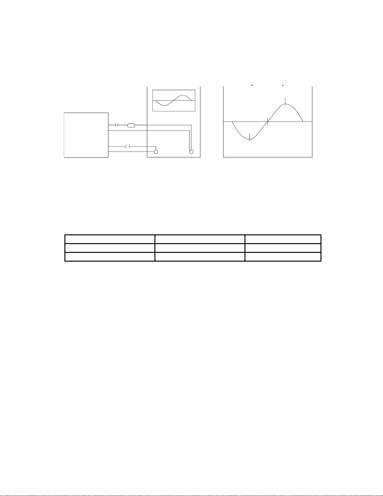
1. Send a FM IF signal through a 1nF capacitor series with a 10K resistor to TP004 (Pin 39 of U1).
2. Detect the IF signal output at TP009 (Pin 10 of U1) through a 4.7 uF capacitor.
3. Align TF006 to obtain a clear display on the oscilloscope without any interference.
4. Ensure that the curve is not saturated.
5. Tune the set to 98.10 MHz
6. Apply an un-modulated mono RF signal at 98.10 MHz with RF input level of 1 mV.
7. Connect a frequency counter to TP003 (Pin 33 of IC001) thru a capacitor 0.1 uF
8. Check TP003 and align TF006 to get US model (10.7 MHz ± 10 KHz). EU/EA model (10.7MHz
±5kHz)
9 Feed a signal 38 dBf, 98.10 MHz (through matching balanced pad) from the signal generator to the
antenna input of the set under test.
PAGE: 4 of 10
TUNER
G
K
10.80
TP-004
TP-004G
TP-009
TP-009
1 nF 10
4.7uF
IN
FIGURE 1
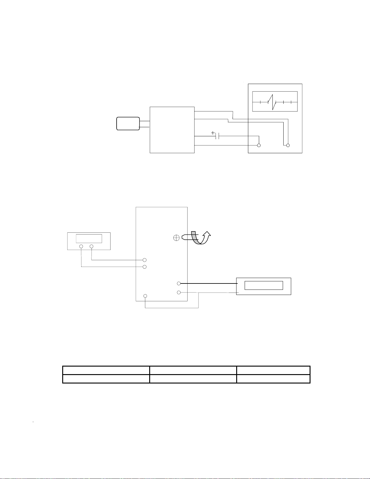
2 FM OSCILLATOR AND RF ALIGNMENT
1. Testing Conditions:
INPUT TP 001 TP001G (RFGND)
OUTPUT TP 007/ TP008 TP009G (AGND)
TUNING VOLTAGE VT TP 002 TP009G (AGND)
1. Set frequency to 87.5 MHz.
Adjust FM Osc coil (L004) to obtain 1.0 ~ 1.05 V at TP 002
10.70
10.60
OUT
FIGURE 2
2. Set frequency to 108.10 MHz.
Adjust Vari-Cap (CV002) to obtain 7.0 ±0.5 at TP002.
3. Repeat the above procedure until the band coverage is fall within the specified VT voltage.
4. Feed a FM RF signal to a matching balanced pad of (50 ohm - 75 ohm) at TP 001 and RFGND.
5. Detect signal from TP 007/008 through the following circuit (Fig 3).
6. Set frequency to 90.10 MHz and adjust L003 until maximum amplitude is reached.
7. Set frequency to 106.10 MHz to see whether approximate amplitude is acquired.
8. Check the amplitude of 98.10 MHz for equal sensitivity.
PAGE: 5 of 10
E
G
1.00V
G
z
DC Voltmeter
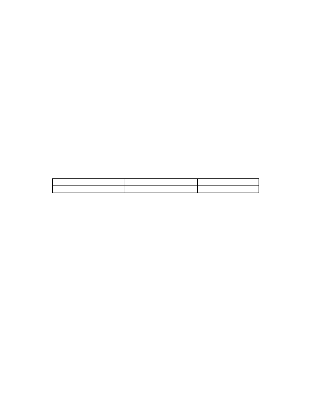
3 FM STEREO ALIGNMENT
FM Signal Generator
TUNER
TP-009
TP-002
TUNER SECTION
TP-001G
TP-007/008
TP-009
TP-001
GENESCOP
4.7uF
FIGURE 3
IN OUT
TP-010
RV-001
TP-001
TP-001G
TP-006
TP-005
FIGURE 5
Frequency Counter
152.000kHz
98.10MH
1. Testing Conditions: (Remove the VT probe during search)
INPUT TP 001 TP001G (RFGND)
OUTPUT TP 005 TP010G (DGND)
2. Apply an un-modulated mono RF signal at 98.10 MHz with RF input level of 1 mV.
3. Search to 98.10 MHz
PAGE: 6 of 10

4. Connect a frequency counter to TP005 (Pin 24 of IC001), short TP010 (Pin 27 of IC001) to ground
TP010G (Pin 26 of IC001) and across a resistor 10K from TP005 to GND
5. Check TP005 and align RV001 to get 152 KHz ± 1 KHz.
6. After the FM stereo alignment, sent a stereo 98.10 MHz signal to the set. Ensure the Stereo
indicator lights up. The signal strength must not be more than 32 dB.
4 AM OSCILLATOR ALIGNMENT
1. Testing Conditions:
INPUT Ant Loop TP001G (RFGND)
OUTPUT TP 007/ TP008 TP009G (AGND)
TUNING VOLTAGE VT TP 002 TP009G (AGND)
MW
2. Set frequency to 530 KHz (US version) & 522 KHz (EU/EA version)
Adjust MW Osc coil (TF003) to obtain 1.4 ± 0.05V at TP 002 for US version
Adjust MW Osc coil (TF003) to obtain 1.35 ± 0.05V at TP 002 for EU/EA version
LW
3. Set frequency to 1710 KHz (US version) & 1611KHz (EU/EA version)
Ensure the MW-VT at TP002 is 8.0 ± 1 V
4. Set frequency to 150 KHz.
Adjust LW Osc coil (TF004) to obtain 1.51 ±0.01V at TP 002
5 Set frequency to 283 KHz
Ensure the LW-VT at TP002 is 4.6 ± 1V
PAGE: 7 of 10
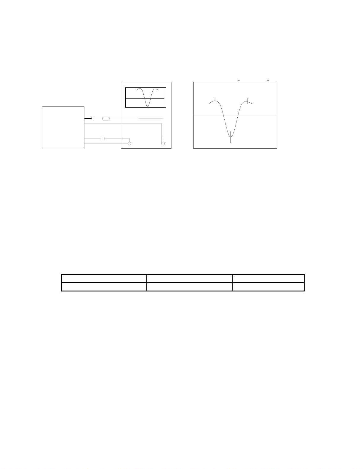
5 AM IF AND AFC ALIGNMENT
1. Testing Conditions: (remove the VT probe during search)
INPUT Ant Loop TP006
OUTPUT TP011 TP004G (IFGND)
2. Send a AM IF signal to TP012 (pin6 of IC001)
3. Detect the signal out at TP009 as below figure 6
4. Adjust TF005 & TF008 until maximal amplitude reached
5. Send an un-modulated RF signal at 1000 KHz (EU version: 999KHz) with RF level of 100mV.
6. Search up/down the receiver. It will stop after acquiring this signal.
7. Connect a frequency counter to TP011 (Pin 36 of IC001) thru a capacitor 1uF
8. Check TP011 and align TF007 to get 450 KHz ± 1 KHz.
PAGE: 8 of 10
TUNER
445
TP-012
TP-004G
TP-009
TP-009G
1uF
4.7uF
FIGURE 6
6 AM RF ALIGNMENT
1. Testing Conditions:
INPUT Ant Loop
OUTPUT TP 007/ TP008 TP009G (AGND)
IN
450
OUT
MW
1. Send a modulated (400 Hz) MW RF signal at 630 KHz with low RF level of 300 uV.
2. Detect signal from TP 007/008 and adjust TF001 until maximum amplitude is reached.
LW
7. Send a modulated (400 Hz) MW RF signal at 170 KHz with low RF level of 300 uV.
3. Detect signal from TP 007/008 and adjust TF002 until maximum amplitude is reached.
PAGE: 9 of 10

MAIN BOARD TAPE ALIGNMENT (SEMI-ENCASING)
Alignment for the cassette portion should be done at the semi - encased stage.
1 AZIMUTH ALIGNMENT
1. In tape transport 1, playback a test tape (TCC-153) of freq. 10 KHz
2. Connect the output to an oscilloscope and a voltmeter.
3. Adjust the azimuth screw at tape head to obtain maximum amplitude on both channels. (Both
channels must be in phase).
4. Repeat the above procedure with tape transport 2.
2 TAPE SPEED ADJUSTMENT
1. Rewind test tape (MTT-111 DN 3khz) until both the left and right hubs are of equal spool.
2. Connect the output to the WOW -FLUTTER METER.
3.
Adjust the trimmer in motor to obtain playback freq. of 3KHz ± 60 Hz if necessary
PAGE: 10 of 10
 Loading...