

Page 1
RCA
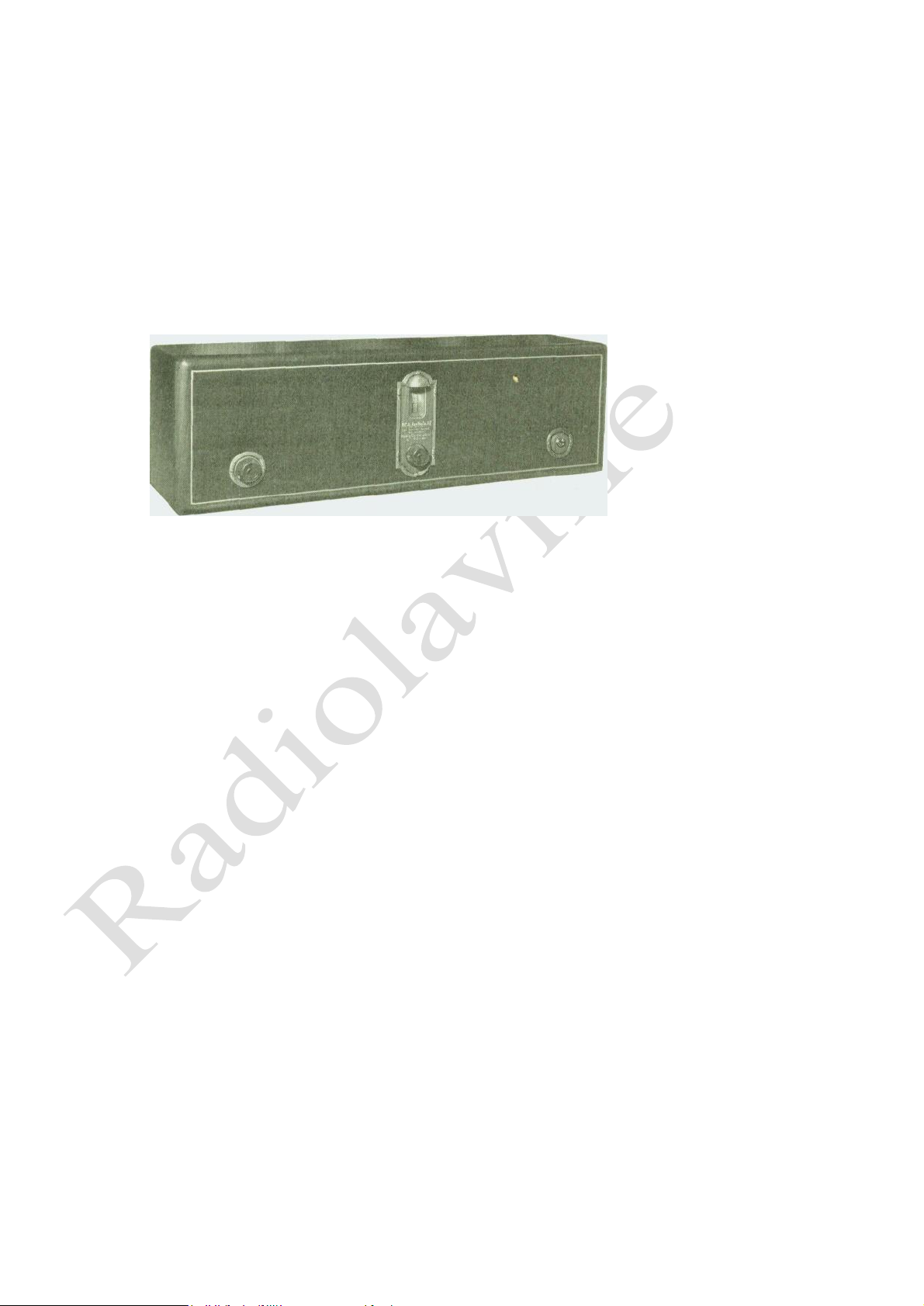
Radiola 17
SERVICE NOTES
RCA Radiola 17
First Edition—Nov. 1927 R17—1
Radio Corporation of America
SERVICE DIVISION OF THE PRODUCTION AND SERVICE DEPARTMENT
233 BROADWAY, NEW YORK CITY
DISTRICT SERVICE STATIONS
326 Broadway 1412 Monroe St., N. W. 2001 West Pershing Road 274 Brannan St.
New York City Washington, D. C. Chicago, 111. San Francisco, Cal.
Page 2

A WORD OR TWO ABOUT SERVICE
Service goes hand in hand with sales. The well informed RCA Dealer renders service at time of
sale in affording information as to proper installation and upkeep. Subsequent service and repair may
be required by reason of wear and tear and mishandling, to the end that Radiola owners may be
entirely satisfied.
Obviously this service can best be rendered at point of contact and therefore Dealers and
Distributors who are properly equipped with a knowledge of the design and operation of Radiolas
occupy a favorable position to contract for this work.
To assist in promoting this phase of the Dealers' business the Service Division of the RCA has
prepared a series of Service Notes—of which this booklet is a part—containing technical information
and practical helps in servicing Radiolas.
This information has been compiled from experience with RCA Dealers' service problems, and
presents the best practice in dealing with them. A careful reading of these Service Notes will establish
their value to Dealer and Distributor, and it is suggested they be preserved for ready reference.
In addition to supplying the Service Notes the RCA, through its Service Stations, has available
to Dealer and Distributor the services of engineers who are qualified to render valuable help in solving
service problems.
Property of Radio Corporation of America. Confidential and to be used only by its authorized distributors
and dealers in furnishing service in connection with its apparatus.
Copyright 1927—Radio Corporation of America.
Page 3

Page
2
5
32
Page
Radiotron Sequence .................................................... 6
Circuit Characteristics ................................................ 6
Radiotrons.....;..................................................... 7
Antenna Installation (Outdoor)........................ 8
Antenna Installation (Indoor)........................... 9
Ground ........................................;.............................. 9
Antenna System Failures ....................................... 10
Radiotron Sockets...............:.............................. 10
Radiotron Prongs........................................................ 10
Loose Volume Control Contact Arm.......... 11
Adjustment for Slack Drum Control........ 11
Mechanical Hum......................................................... 12
Broken Condenser Drive Cable........................ 13
Loudspeaker Polarity .
Uncontrolled Oscillation
Distorted Reproduction
Audio Howl ......................
Acoustic Howl ........
Hum ............................
Line Control Switch ............
Wiring Cable .............................
Pilot Lamp and Canopy
Filter Condensers ..................
Voltage Readings ..................
Grid and Plate Voltages
Heating of Cabinet ...............
Continuity Tests .....................
Page
13
. 14
.... 15
.. I5
.... 16
... .16
......18
..... 19
..... 19
..... 20
..... 20
..... 21
..... 22
..... 23
Page
Replacing Volume Control ........................................... 24
Replacing Radio Frequency Coils................................... 25
Replacing Radiotron Gang Sockets................................. 26
Replacing Main Tuning Condensers and Drive …...... . 26
Replacing Large By-Pass Condensers............................. 27
Replacing Audio Transformers ....................................... 28
Replacing Output Transformer........................................ 28
Page
28
29
30
30
31
31
31
Replacing Condenser Drive Cable.........
Replacing Dial Scales............................................
Replacing Power Cable................................
Replacing Filter Condenser Assembly....
Replacing Either Power Transformer or Filter Reactor
Replacing Terminal Strip
Replacing Miscellaneous Parts in S.P.U....
R F. Transformer Connections...................................24
By-Pass Condenser Connections................................25
A. P. Transformer Connections..................................26
Output Transformer Connections...............................26
Replacing Dial Scales ...............................................27
Color Scheme of Power Cable Connections………. 29
A Word or Two About Service ………
Introduction …………..........................
Service Data Chart................................
CONTENTS
PART I—SERVICE DATA
PART II—MAKING REPLACEMENTS
RCA Radiola 17 ...............„.............................:........ 1
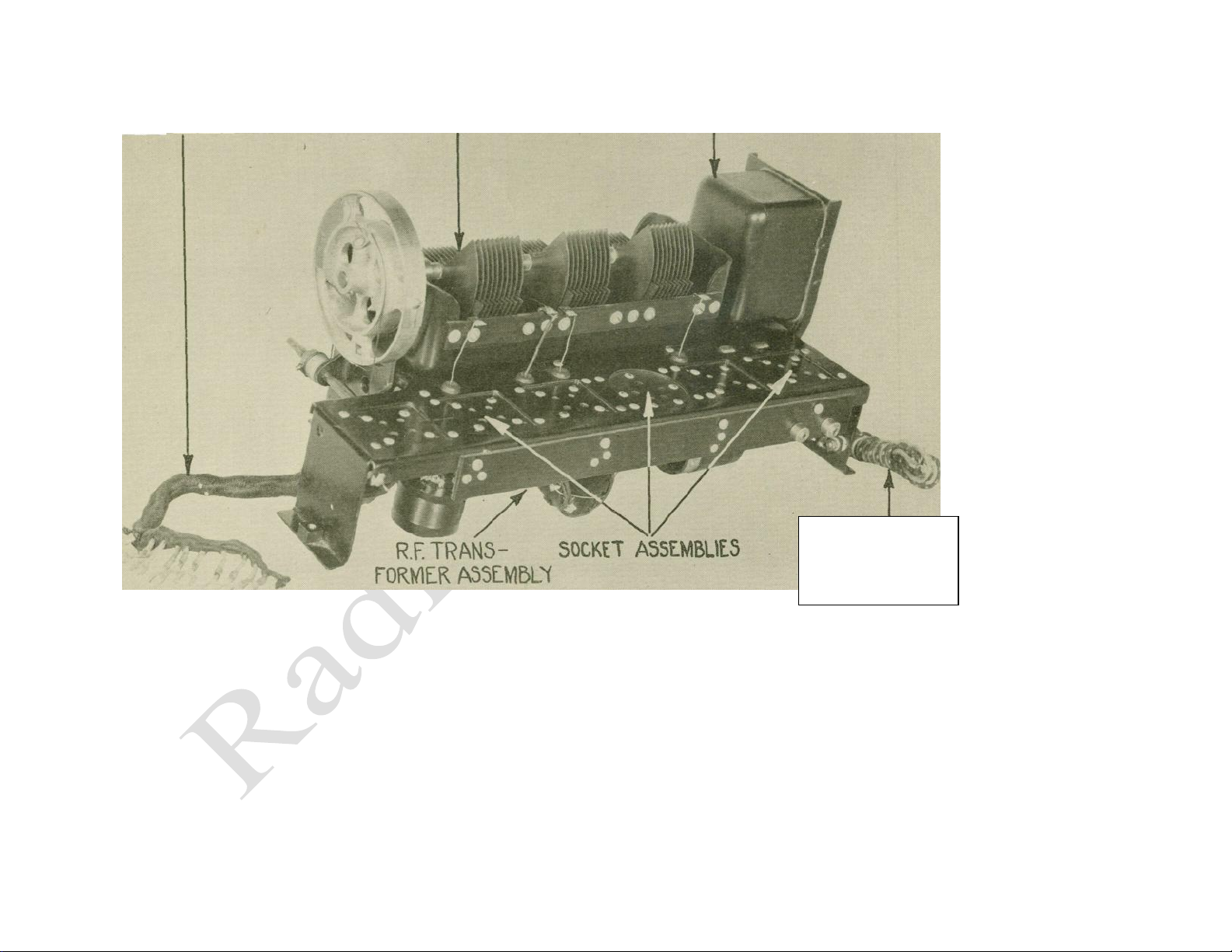
Top View of Chassis Assembly................................. 4
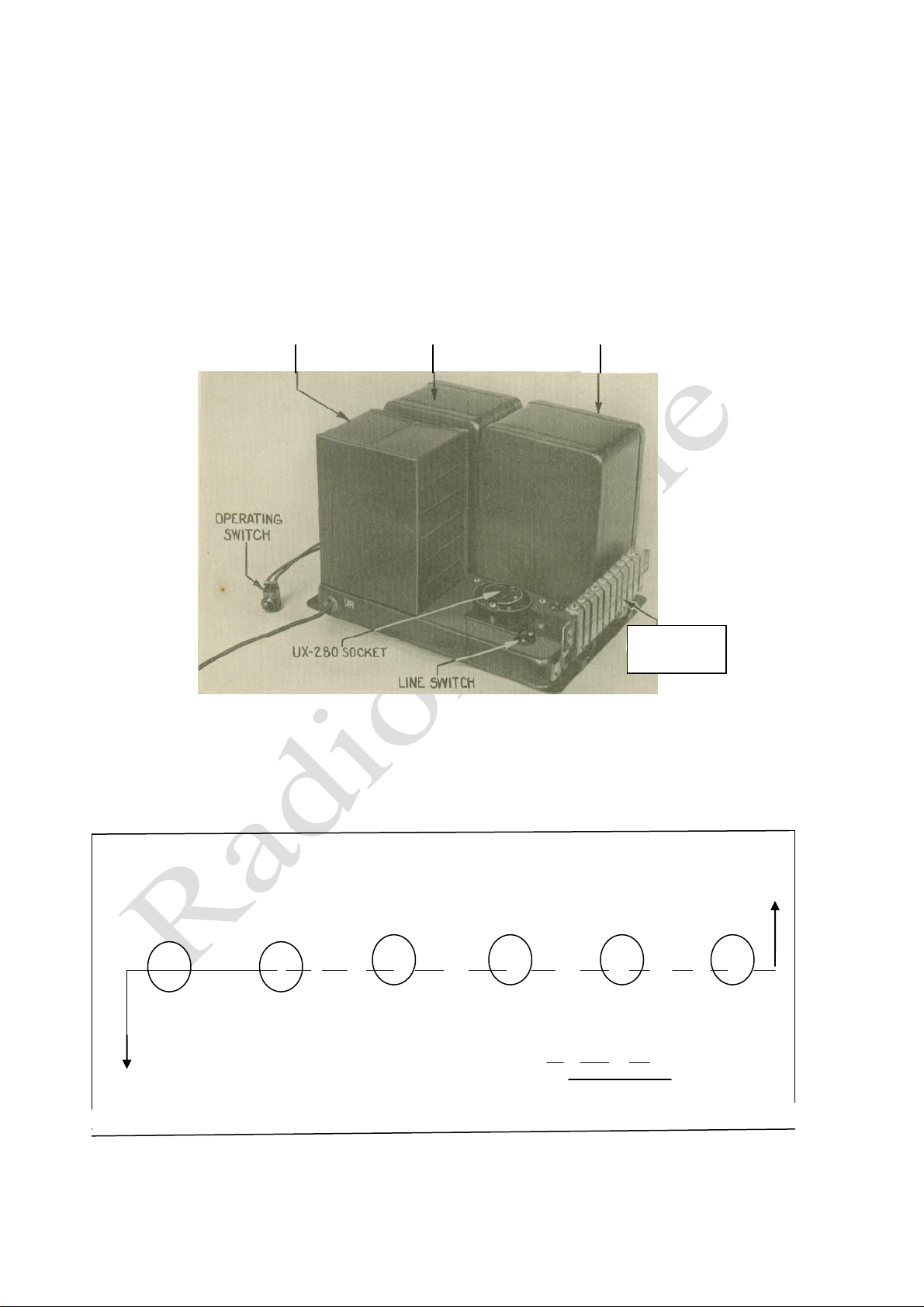
Socket Power Unit Showing Parts.................................. 5
Radiotron Sequence ................................................... 5
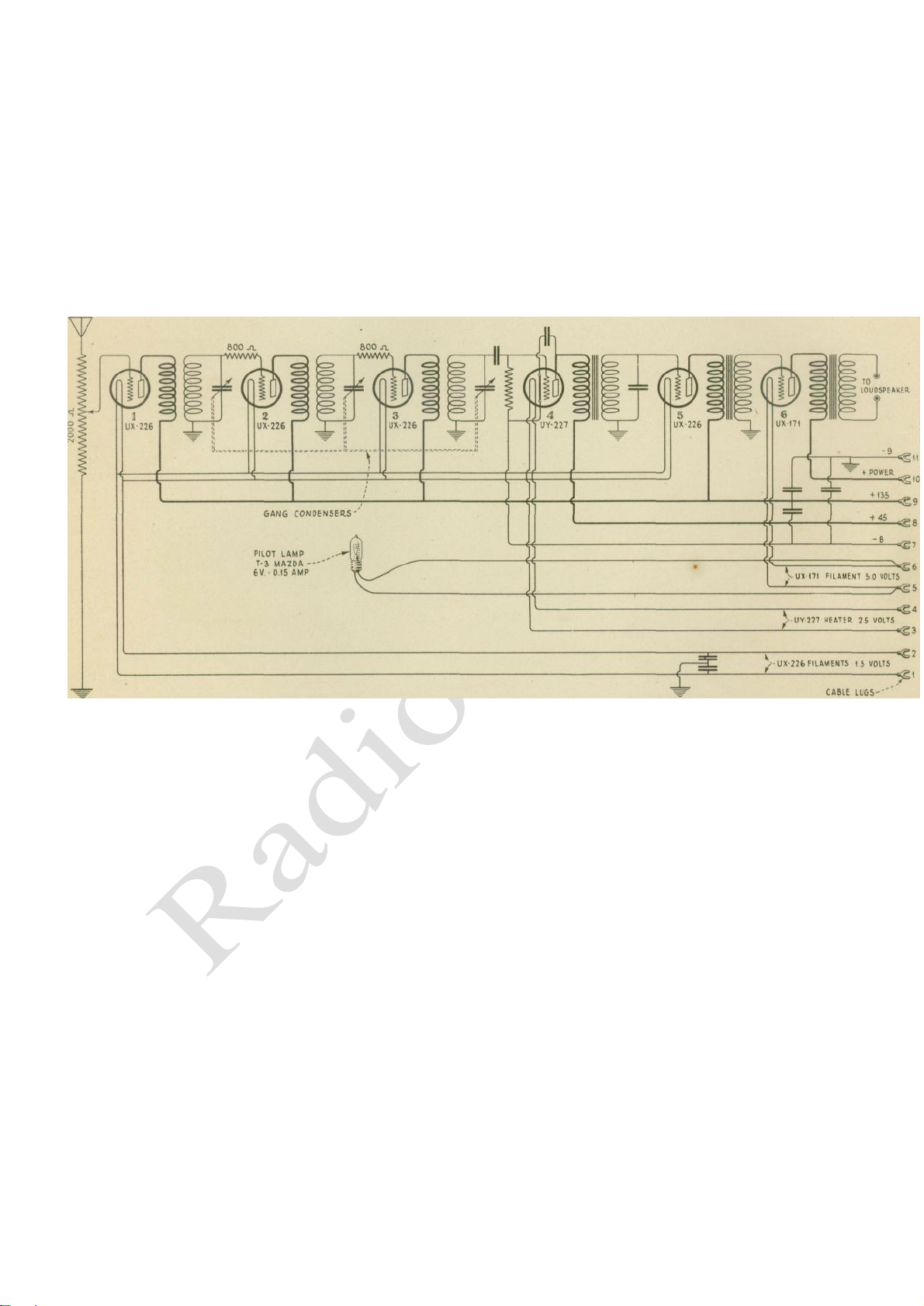
Schematic Circuit Diagram of Receiver………………. 6
Schematic Circuit Diagram of S.P.U.............................. 7
Radiotron Socket Contacts ........................................ 8
Method of Cleaning Radiotron Prongs.......................... 9
Releasing Volume Control ......................................... 10
Adjusting Contact Arm of Volume Control ................ 11
Turning Cable Adjusting Screw...... …………… .. 12
Condenser Cable and Drum Mechanism……………. 13
Schematic Circuit for Resistance Measurement.......... 14
Adjusting Potentiometer tor Minimum Hum ............. 16
emoving Receiver Assembly from Cab-22
ILLUSTRATIONS
Page
View of Pilot Light Socket and Canopy. …….….... 17
Wiring Diagram of Sub-Chassis Assembly ……....... 18
Continuity Wiring Diagram of S.P.U.......................... 19
Internal Connections of Filter Condensers ............... 20
Schematic Circuit for Securing Grid Voltages.......... 21
Removing Receiver Assembly from Cabinet…… ….22
Page
Page 4
ANTENNA AND
GROUND
CONNECTIONS
POWER CABLE TUNING CONDENSERS OUTPUT TRANSFORMER
Figure 1—Top view of chassis assembly showing the principal parts.
Page 5
TERMINAL
STRIP
RCA RADIOLA 17
SERVICE NOTES PREPARED BY RCA SERVICE
DIVISION
INTRODUCTION
RCA Radiola 17 is a six-tube tuned radio frequency receiver (Figure 1), utilizing RCA Radiotrons
UX-226, UY-227, UX-171 and the Radiotron full wave rectifier UX-280 in the socket power unit
(Figure 2). The use of Radiotrons UX-226, UY-227, and UX-171, using raw alternating current for
filament supply,
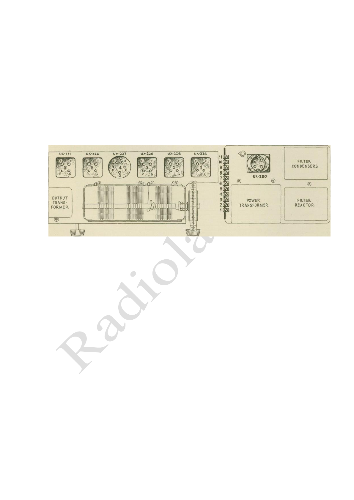
FILTER CONDENSERS FILTER REACTOR POWER TRANSFORMER
Figure 2—Socket Power Unit showing various parts.
and Radiotron UX-280 in a plate and grid supply unit makes Radiola 17 a complete socket power
receiver operating on 105-125 volts, 50 to 60 cycle A. C. lines.
Very little service work should be required on Radiola 17. However, the following notes are
published for the guidance of those called upon to locate and remedy any trouble that may occur.
To
Ant
6 5 4 3 2 1
nd
2
1st Detector 3rd 2nd 1
A.F. A.F.
R.F. R.F. R.F.
st
Radio Frequency
To
Loudspeaker
Figure 3— Radiola sequence in RCA Radiola 17
Page 6
PART I—SERVICE DATA
(1) RADIOTRON SEQUENCE
Figure 3 illustrates the sequence of the Radiotrons in the receiver proper, omitting Radiotron UX280 in the socket power unit. From right to left, when facing the front of the Radiola, the Radiotron
sequence is as follows:
Radiotron No. 1 is an untuned stage of radio frequency amplification. It is coupled directly to the
antenna and ground and is not tuned in any way.
Radiotron No. 2 is a stage of tuned R. F. amplification employing a grid resistance to prevent
oscillation. It is tuned by the first gang condenser.
Radiotron No. 3 is the second stage of tuned E. F. amplification. It also
Figure 4—Schematic circuit diagram of receiver assembly.
employs a grid resistance for the purpose of stabilizing or preventing self oscillation in the circuit. It is
tuned by the second of the main tuning condensers. Radiotron No. 4 is the detector tuned by the thirdgang condenser. Radiotrons No. 5 and No. 6 are respectively the first and second stages of audio
frequency amplification. The last stage, Radiotron No. 6, employs power amplifier Radiotron UX-171.
(2) CIRCUIT CHARACTERISTICS
The following principles are incorporated in the circuit design of Radiola 17
(Figure 4 and 4A.)
1. A three-gang condenser, employed to tune two of the radio frequency circuits and the detector
circuit, provides one tuning control.
2. An aperiodic antenna, or first E. F. circuit, eliminates the necessity for a separate antenna tuning
control.
3. The volume control regulates the input grid voltage to the first R. F. amplifier stage. This is the most
practical method of volume control for use
6
Page 7
with A. C. Radiotrons and gives a smooth control of volume without distortion.
4. No neutralizing condensers are employed. Grid resistances in the two tuned radio frequency stages
effectively prevent any tendency to self oscillation.
5. Raw A. C. of the correct voltage is used for filament heating of all Radiotrons. This eliminates the
use of "A" batteries.
6. The three B. F. stages and the first audio stage receive a plate voltage of 135 volts in conjunction
with a negative grid bias of 9 volts. The detector receives 45 volts plate supply without grid bias. The last
audio stage receives a, plate supply sufficient to provide ample loudspeaker output. The plate and grid
voltages are supplied by means of a built-in " B " and " C " supply using Radiotron UX-280 as the
rectifying device.
7. Radiotron UX-171 in the last audio stage provides ample volume without distortion in loudspeaker
reproduction.
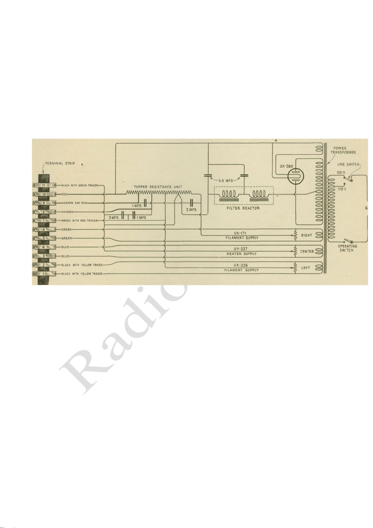
Figure 4A—Schematic circuit diagram of socket power unit.
The various circuit characteristics of Radiola 17 provide for easy installation and simple operation
coupled with quality reproduction delivered to the loudspeaker.
(3) RADIOTRONS
Radiotrons UX-226 are used in all radio frequency amplifying stages and in the first audio
amplifying stage. It has an oxide coated filament consuming 1.05 amperes at 1.5 volts.
Radiotron TJY-227 is used for the detector. It operates on raw A. C. for filament supply, making
use of an indirectly heated cathode. This Radiotron has five prongs, the extra prong being connected to
the oxide coated cathode. Under normal conditions Radiotron UY-227 should give little trouble.
However, in some cases a slight howl may develop in the detector circuit which will necessitate
substituting another UY-227 Radiotron. Although a howl may develop in a receiver with one UY-227,
in another the same tube may prove 0. K. On examining a Radiotron UY-227 in operation, a slight
flickering of the heater
7
Page 8
(4)
element, incased in its insulating material, may be noticed. This condition in no way affects the normal
operation of the Radiotron. The lag in the transference of heat from the heater element to the cathode, as
evidenced when starting and stopping the operation of the tube, takes care of any variations indicated by
this flicker, which supposedly might affect the normal operation of Radiotron UY-227. In Radiola 17
there is a positive potential of 9 volts applied to the cathode of Radiotron "UY-227 with the negative side
of this potential connected to the center connection of the potentiometer across the heater winding for this
Radiotron. This prevents a possibility of the cathode emitting any electrons back to the heater instead of
to the plate.
The power-amplifier Radiotron UX-171 in the last audio stage is interchangeable with the new
EGA Radiotron UX-171A. An output transformer protects the loudspeaker windings from the high plate
voltage used with this Radiotron.
Radiotron UX-280 is a full wave rectifying Radiotron used to rectify the alternating current into
pulsating direct current, which is smoothed out by means of a filtering system, and used to provide all
plate and biasing voltages.
Figure 5—Radiotron socket contacts
ANTENNA INSTALLATION (Outdoor Type)
Due to the high sensitivity of Radiola 17 the most efficient antenna system is one of
approximately 25 feet in length—depending upon local conditions—measured from the far end
of the antenna to the ground connection. It should be erected as high as can be conveniently arranged
and as far removed from all obstructions as possible. The lead-in should preferably be a continuation
of the antenna itself, thus avoiding all splices which introduce additional resistance to the antenna
system and which may in time corrode sufficiently to seriously affect reception. If, however, it is
absolutely necessary to splice the lead-in to the antenna, the joint must be carefully soldered to insure a
good electrical contact. Excess flux should be cleaned off and the connection carefully covered with
rubber tape to protect it from the oxidization effects of the atmosphere.
The antenna and lead-in should be supported by high grade glass or porcelain insulators. At no
point should the antenna or lead-in wire come in contact with any part of the building. The lead-in wire
should be brought through the wall or window frame and insulated therefrom by a porcelain tube. The
use of a flat "window-strip" type of lead-in is not recommended.
8
Page 9
The antenna should not cross either over or under any electric light, traction or power line and
should be at right angles to these lines and other antenna. It is desirable to keep the lead-in a foot or
more from the building where possible. When an outdoor antenna is used it should be protected by
means of an approved lightning arrester, in accordance with the requirements of the National Fire
Underwriters' Code.
(5) ANTENNA INSTALLATION (Indoor Type)
"Where the installation of an outdoor antenna is not practical, satisfactory results may generally
be obtained by using an indoor antenna consisting of about 25 feet of insulated wire strung around the
picture molding or placed under a rug. In buildings where metal lathing is employed satisfactory
results are not always possible with this type of antenna. Under such conditions various arrangements
of the indoor antenna should be tried to secure satisfactory results. An indoor antenna is not as
efficient as a properly installed outdoor antenna.
Figure 6—Method used to clean Radiotron prongs.
(6) GROUND
A good ground is quite as important as the antenna. No specific recommendations can be given
in this matter as conditions vary in different locations. Water and steam pipes usually make good
grounds. G-as pipes usually make poor grounds and, as a rule, are to be avoided. If neither water nor
steam pipes are available, a pipe or metal rod may be driven into the ground to a depth of several feet.
The success of this type of ground depends upon the moisture present in the soil. The ground lead
should be. connected by means of an approved ground clamp to a section of pipe that has been scraped
and thoroughly cleaned. The connection should be inspected from time to time to make certain that a
clean and tight electrical contact exists between the clamp and pipe.
It is recommended that the service man experiment with various grounds, and employ the one
giving the best results. Radiola 17 is capable of receiving over good distances when connected to an
efficient antenna and a low resistance ground.
9
Page 10
If the results of experiments seem to indicate that a good ground is not possible, the use of a
counterpoise is suggested if local conditions permit. A counterpoise is in effect a second antenna. It
should be about six feet above ground, well insulated, of the same dimensions as the antenna and
located directly under it. The counterpoise is connected to the Radiola in place of the ground
connection.
(7) ANTENNA SYSTEM FAILURES
Complaints of swinging signals, or of intermittent reception with probable grating noises, as
distinguished from fading effects, are generally the result of antenna and ground system failures and to
this, therefore, the service man should give his first attention. A grating noise may be caused by a poor
lead-in connection to the antenna, or antenna touching some metallic surface, such as the edge of tin
roof, drain pipe, etc. By disconnecting the antenna and ground
Figure 7—Releasing mounting screws holding volume control.
leads from Radiola 17 and noting whether or not the grating continues, the service man can soon
determine whether or not the cause of complaint is within or external to the receiver and plan his
service work accordingly.
(8) RADIOTRON SOCKETS
The sockets in Radiola 17 are of the standard gang UX and UY type (Figure 5). The three-gang
socket is for the radio frequency amplifiers; the single socket—a five-prong detector socket is for
Radiotron UY-227 and the two-gang socket is for the audio frequency amplifiers. Care must be
exercised when inserting Radiotrons in the sockets. A socket contact may not be in its correct position
and forced insertion of a tube will bend or break it. If care is exercised and the Radiotron inserted
gently, little trouble will be experienced with socket contacts. A bent one will be noticeable on
inspection and may be corrected by inserting a narrow instrument in the socket hole and pushing the
contact into its correct position. A badly bent or broken socket contact must be replaced.
(9) RADIOTRON PRONGS
Dirty Radiotron prongs may cause noisy operation or change the resistance of the filament circuit
sufficiently to cause a hum in the loudspeaker. They should therefore be cleaned periodically to insure
good contact.
10
Page 11

The potentiometers (Part I, Section 19) should be readjusted for the position of minimum hum
whenever the Radiotron prongs are cleaned.
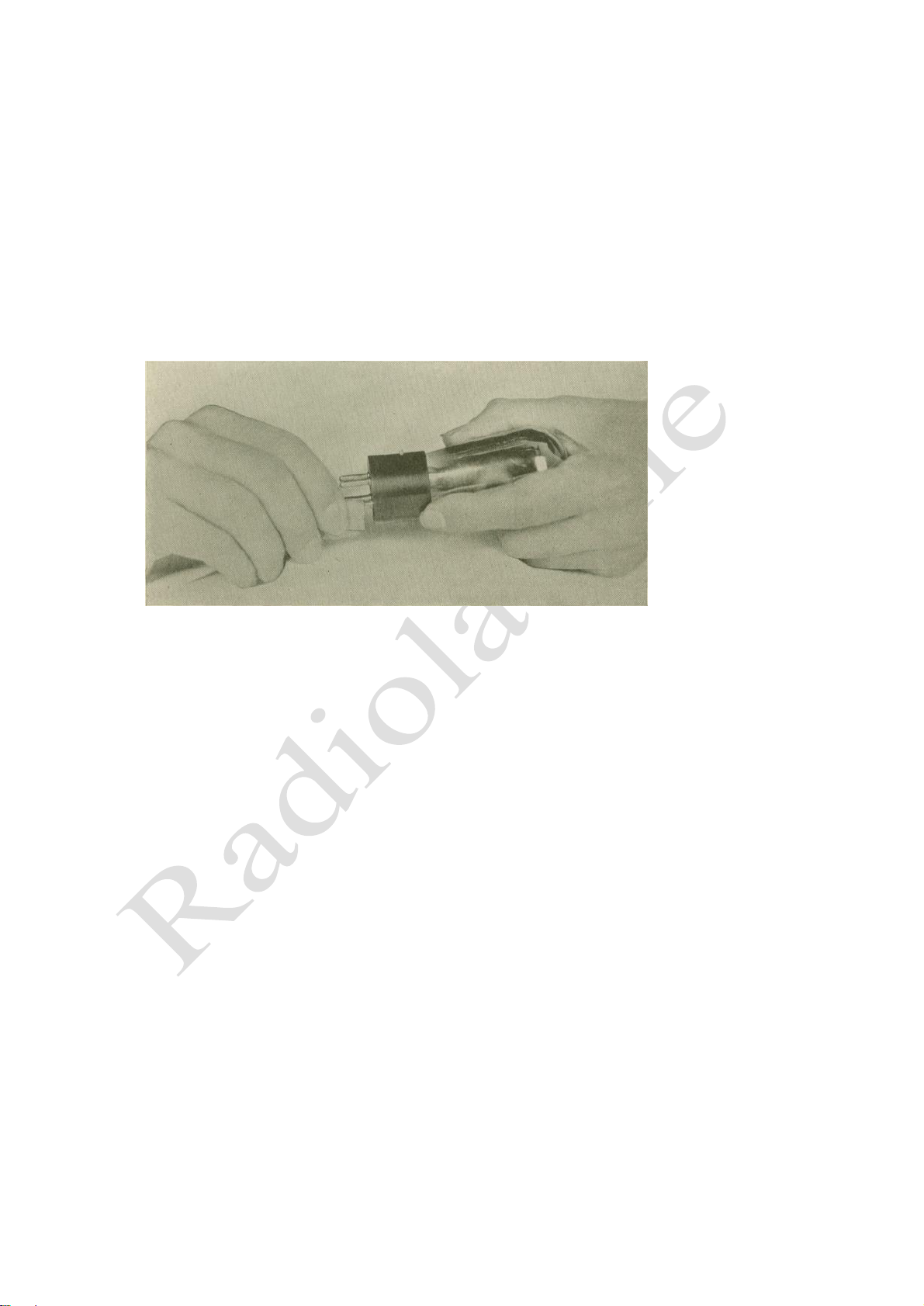
The prongs should be cleaned by using a piece of fine sandpaper (Figure 6). The use of emery
cloth or steel wool is not recommended. Before re-inserting Radiotrons in their sockets wipe the
prongs and base carefully to make certain that all particles of sand are removed.
In placing Radiotrons in the UX sockets care should be exercised to make certain that the two
large pins and two small pins of the Radiotrons match the socket holes. The UY-227 Radiotron has
five prongs all of the same size and will fit in the socket only one way. If a Radiotron will not fit into
a socket without considerable pressure being applied, look for excessive solder on one or more of the
prongs. Excessive solder on prongs may be removed with a file or knife.
Figure 8—Adjusting the contact arm to secure improved contact
with resistor strip.
(10) LOOSE VOLUME CONTROL CONTACT ARM
A loose volume control contact may cause noisy or intermittent operation and should be
remedied. If the contact arm is loose, the remedy is to bend it slightly so that it makes firm contact
against the resistance strip. In order to do this it is necessary to remove the chassis from the cabinet as
described in Part II, Section 1. The volume control is then readily accessible. By removing the two
screws (Figure 7), that hold it to the metal frame it may be completely removed. The small U-shaped
washer is removed from the shaft and the spring contact arm is pulled out to clear the resistor strip.
The spring contact arm may now be bent sufficiently to make a good contact. Figure 8 illustrates the
bending of this contact arm. After adjusting the spring contact arm, replace the mounting screws and
return the chassis to the cabinet and replace screws and control knobs.
(11) ADJUSTMENT FOR SLACK DRUM CONTROL
The main tuning condensers are controlled by a cable and drum arrangement giving a smoothly
acting vernier movement that has no back lash. (See Figure 10.)
11
Page 12

After considerable wear, or extreme changes of temperature the cable may become slack. To take
up this slack open lid of cabinet and turn the cable adjusting screw with clamp until the cable is taut.
(See Figure 9.) In extreme cases as might occur after considerable use and several adjustments this
screw may become seated thus allowing no further tightening of the cable. When this condition occurs
it will be necessary to slip the cable a half turn on the grooved drum. To make this adjustment it is
necessary to remove the chassis from the cabinet as described in Part II, Section 1. Remove the cable
adjusting screw and clamp (see Figure 10). The cable will then have approximately one inch slack. By
removing the tapered pin holding the front grooved drum to its shaft and replacing it on the opposite
side (180 degrees) the one-inch slack in the cable can be taken up by using the new position of the pin
for anchoring the cable. Figure 10 illustrates this operation. It will be noted that the tapered pin in the
Figure 9—Turning cable adjusting screw to take up slack in tuning drum cable.
new position cannot be inserted as far as originally. However, it can be inserted far enough to lock the
grooved drum to the control shaft and clear the metal housing. If the cable again is stretched to the
maximum adjustment of the cable adjusting screw the tapered pin can be returned to its original
position and a half turn slipped on the drum which will provide for taking up all slack. Sufficient
grooves are provided on the drum for this purpose.
(12) MECHANICAL HUM
A mechanical hum caused by vibration of loose laminations in the power transformer may be
corrected by removing the power transformer from the S. P. XL as described in Part II, Section 12, and
heating it in a slow oven. The open end of the transformer should be kept up and the wax heated
sufficiently to allow it to adhere to the laminations of the transformer. After heating, the transformer
should be allowed to cool for at least 24 hours and then returned to the S. P. U.
12
Page 13

MAXIMUM
ADJUST OF CABLE
ADJUSTING SCREW
CABLE ADJUSTIJNG SCREQ
REMOVED TO ALLOW
HALF-TURN EXTENSION
OF CABLE ON DRUM
DOTTED LINES INDICATE
REFERSAL OF PIN AND HALFTURN EXTENSION OF CABLE
ON DRUM
(13) BROKEN CONDENSER DRIVE CABLE
Should a cable become broken, due to considerable use or excessive tightening, the proper
remedy is to replace the cable. The procedure for making this replacement is described in Part II,
Section 8. However if a new cable is not immediately available a temporary repair may be made in the
following manner provided the break in the cable is not in that section that passes over the small
grooved drums.
The two ends should be spliced together and then soldered. Splicing consists of interweaving the
strands as with rope and not just twisting the cable
Figure 10—Radiola 17 three-gang condenser cable and
drum operating mechanism.
ends together as in an electrical wiring splice. Splicing gives greater strength and results in a smaller
body being formed on the cable. When soldering, use plenty of flux and a small amount of solder.
Heat sufficiently long for the solder to adhere to all the small strands of the cable.. Placing the splice
in an alcohol or bunsen flame affords sufficient heat and allows any excess solder to drip away. It is to
be understood that this is but a temporary repair and should be used only until a new cable can be
procured and installed.
(14) LOUDSPEAKER POLARITY
Due to Radiola 17 using an output transformer, there is no polarity to the output current of the
receiver. Consequently, when connecting any type of loudspeaker (either horn type or cone type) the
speaker should be connected in the manner that gives the most pleasing reproduction.
13
Page 14

MA
(15) UNCONTROLLED OSCILLATION
Should Radiola 17 oscillate or regenerate at any point in the tuning range the trouble is probably
caused by:
1. Defective grid resistor in second or third E. F. stages.
2. Excessive filament voltage.
3. Antenna lead too close to third E. F. transformer.
4. Detector tube howling.
In the case of No. 1 the grid resistance of Radiola 17 may be checked by means of a resistance
bridge. If' a resistance bridge is not available the voltmeter-ammeter method gives accurate results
provided the meters used are calibrated accurately. This method makes use of a milliammeter with a
scale of 0-500 and a voltmeter of 0-7 volts. A voltage is then applied that will give a substantial
reading. A circuit diagram of this method is shown in Figure 12.
E VOLTS
ACROSS RESISTANCE R= ______ OR 1000 ____________
TO BE MEAUSERED I MILLIAMPERES
V 0-7 6 VOLTS
0 - 500
Figure 12—Schematic circuit for resistance measurement.
The resistance may then be calculated by the use of Ohms law.
E
R ==— (Where R equals ohms, E equals volts and I equals amperes)
I
Volts
or 1000 ___________
Milliamperes 1
Since the current reading is taken in milliamperes (or —— ampere) it is necessary
to multiply by 1000 to get the resistance value in ohms. 1000
In the case of No. 2 the line switch should be placed at the position of minimum brilliancy for
the pilot lamp. Excessive filament voltage on the E. F. amplifiers may cause these tubes to oscillate at
some point on the tuning scale.
In No. 3 the remedy is to place the antenna lead at a greater distance from the third E. F.
transformer than that normally used. This can be done by slipping the antenna lead from under the
chassis and taking it out of the cabinet close to its connection at the volume control.
A detector tube may cause oscillation or a howl, very similar to a microphonic howl. The remedy
in this case is to interchange the detector Radiotron with another UY-227 Radiotron. A tube may howl
in one Radiola 17 and perform normally in another.
14
Page 15

In some cases with certain antennas, the Radiola may oscillate even though everything is 0. K.
The remedy is to change the antenna length or interchange the UX-226 Radiotrons in the R. F. stages.
(16) DISTORTED REPRODUCTION
Under normal conditions Radiola 17 will deliver a strong signal of good quality to the loudspeaker.
If the loudspeaker production is poor test the loud speaker output from the receiver. A pair of phones or
a loudspeaker of known quality may be used for this purpose. Poor quality or distortion may be due to
any of the following causes:
1 High or low plate and grid voltages from socket power unit This may be due to a defective
Radiotron UX-280 or tapped resistance unit. The remedy is to replace the Radiotron UX-280 with one of
known quality or check the various resistances of the tapped resistor for a possible short or open. _
2 Defective Radiotrons. Though the Radiola may be in operating condition a defective Radiotron in
any stage will cause distortion. This is especially true of the detector, 1st and 2nd audio stages and the
rectifier tube.
3.. Potentiometers not properly adjusted. Unless the potentiometers are correctly adjusted sufficient
hum may be present to cause distortion. The correct adjustment of these potentiometers is described in
Part I, Section 19
Should Radiola 17 become noisy in operation or signals come in and die out abruptly with periods
of hum or no reception, test in the following manner:
(a) Disconnect antenna and ground leads. If the Radiola becomes quiet and signals from local
stations, though weak, are received it would be an indication that the trouble is either in the antenna
system or is caused by nearby interfering electrical apparatus. The remedy in the first case is to repair
the antenna system and in the second place Radio Frequency chokes on any offending nearby
apparatus. The location of interfering electrical machinery and the cure will require patience, skill and
experimenting.
(b) If disconnecting the antenna and ground system does not eliminate the noise the trouble is in
the Radiola. A defective tube, one having poorly welded elements would cause a disturbance of this kind
and this point should be checked by interchanging the Radiotrons in the Radiola with others of the
same type. If it is definitely established that the Radiotrons are ok then the contact between the
Radiotron prongs and the socket contacts should be examined for a dirty or poor contact. The three
potentiometers in the Socket Power Unit and the Volume Control should be examined for a dirty or poor
contact between the contact arm and the resistor strip.
(17) AUDIO HOWL
Radiola 17 may have a tendency to howl when first installed. This can usually be remedied by
interchanging the detector Radiotron with another UY-227 Radiotron. If this does not remedy the
trouble try the following:
(a) Put the line control switch in the position that gives the least light at the pilot lamp. This
reduces the filament voltage on all the Radiotrons which may be high, causing oscillation on the part of
the R. F. amplifiers.
15
Page 16

(b) Place antenna lead at a greater distance from third R. F. transformer than that normally used by
slipping it from under the chassis and taking it out of the cabinet close to its connection at the volume
control.
If the Radiola has been in operation for a considerable time and a howl develops, the following
points should be checked for possible defect:
(a) Defective Radiotrons. A Radiotron after considerable use may cause a howl. Substituting a
Radiotron of known condition will isolate the defective one.
(b) Open audio by-pass condensers.
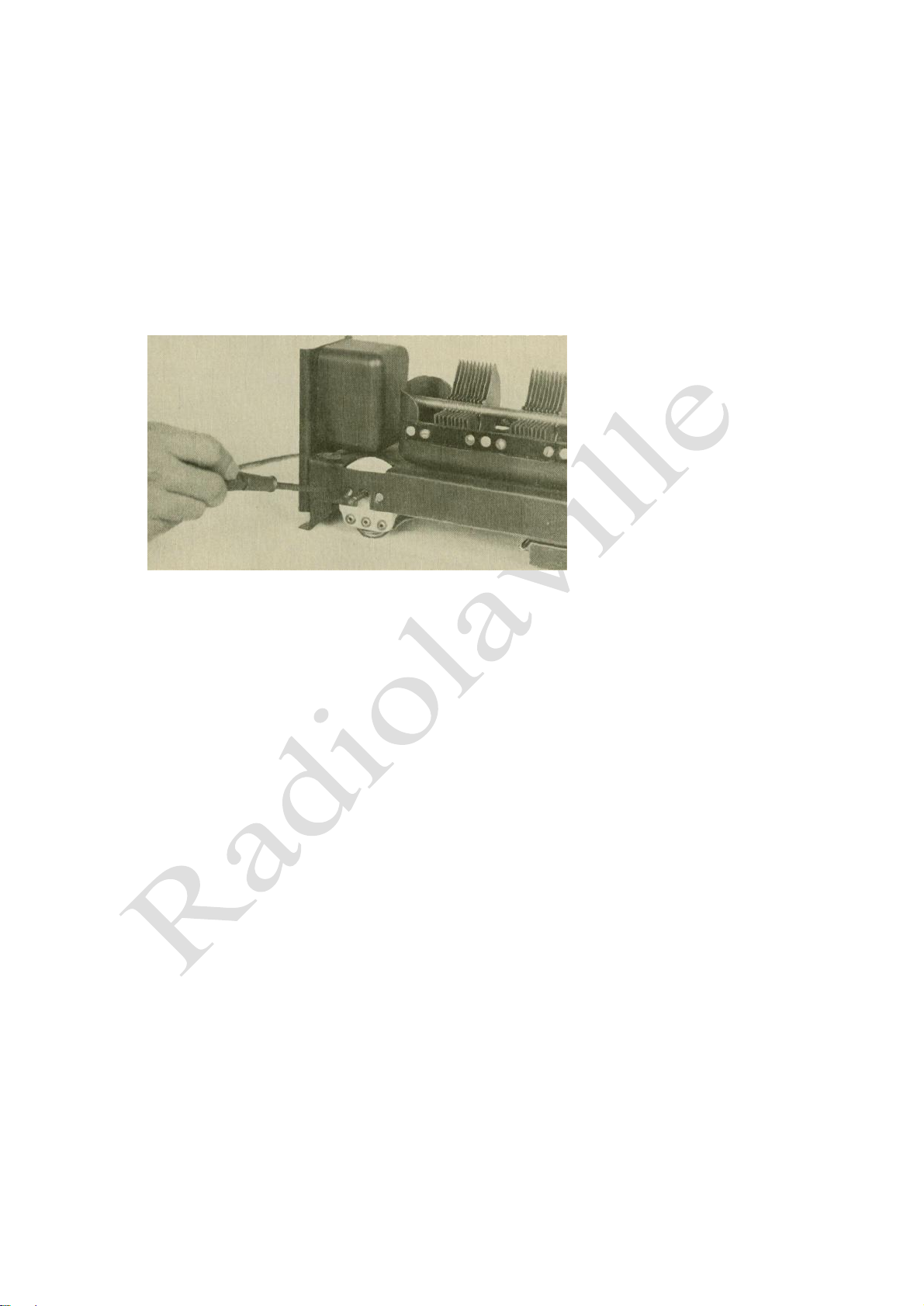
Figure 13—Using a long screwdriver in adjusting the
potentiometer for minimum hum.
(c) Defective grid leak or open grid connection of any tube in the Radiola
except Radiotron UX-280.
(d) Open E. F. grid resistor.
Any part found defective should be replaced and any open or poor connection should be repaired.
(18) ACOUSTIC HOWL
Generally speaking, Radiola 17 is much less susceptible to acoustic howling
due to microphonic tubes than receiving sets using other than A. G. tubes. However on some occasions
acoustic howling may be experienced and the loudspeaker location must be chosen with care. This
howl is somewhat different from the usual microphonic howl in that it disappears when a station is
tuned in, but still causes some distortion in the received signal. The remedy is to interchange the UY-
227. detector tube with another of a similar type or change the position of the loudspeaker. In extreme
cases both remedies may be necessary.
Three potentiometers are provided in Radiola 17 for the suppression of any AC hum These
potentiometers are adjusted for the correct electrical center of the filaments of Radiotrons UX-226, UY227 and UX-171. The following procedure should be used in eliminating hum:
16
Page 17

(a) Place set in normal operation with loudspeaker connected.
(b) Remove Radiotrons 2 and 3, counting from left to right (first audio and detector stages facing
front of Radiola).
(c) Locate position of three potentiometers in power unit.
(d) Adjust potentiometer, located at extreme right when facing front of Radiola (Figure 13), for
position of minimum hum.
(e) Now replace Radiotron No. 2 (UX-226), previously removed, and
Figure 14—Detailed view of the pilot light socket and canopy.
adjust the potentiometer located at the extreme left (facing the front of the Radiola) for position of
minimum hum.
(f) Replace Radiotron UY-227 and with the Radiotron in normal operation
adjust the center potentiometer for minimum hum.
Under normal conditions these three adjustments will suppress any noticeable hum in the
loudspeaker.
If the foregoing procedure does not reduce hum, try the following:
(a) In some cases when adjusting the potentiometers there may he no apparent point of minimum
hum. This is due to low line voltage and may be remedied by throwing the line switch to the position
that gives maximum brilliancy of the pilot lamp. If this does not remedy the trouble, try changing the
position of the line switch to each location several times. There may be a dirty contact in this switch,
making a high resistance connection which may cause the filaments to glow below normal brilliancy.
When this condition is present it will be impossible to adjust the potentiometers for minimum hum
until the filament
temperature of all Radiotrons is normal.
(b) When adjusting the UX-226 potentiometer (at the left) it may be noted that the position of
minimum hum is at one extreme of the potentiometer. When this is encountered the potentiometer
should be arbitrarily placed at its center position and then the UY-227 Radiotron placed in its socket
and the center potentiometer adjusted for minimum hum. The left potentiometer may now be re-ad-
17
Page 18

justed for a further minimum value, which will not now be located at one of
the extreme positions.
(c) After making any potentiometer adjustment, further reduction of hum may be attempted by
reversing the input plug.
When adjusting the potentiometer at the extreme right with a metallic screw driver a flash will occur
from the screw driver to any part of the frame that the screw driver may touch. This is normal and does no
harm. If it is desired to avoid this condition, an insulated shaft screw driver or a metallic screw driver
wrapped with insulating tape should be used.
(.d) If these various adjustments suppress the A. C. hum correctly, but after a short time the hum
reappears it is a good indication that some of the
Figure 15—Wiring diagram of sub-chassis assembly showing color scheme
and connections with relative location of parts.
Radiotrons are making poor socket contacts, thus destroying the electrical center of the filament
potentiometers. These prongs should be cleaned as described in Part I, Section 9.
If at any time the Radiola is changed from one electrical outlet to another outlet or Radiotrons are
interchanged or replaced with others it may be necessary to readjust one or more of the potentiometers.
(20) LINE CONTROL SWITCH
The line switch should be kept at the position of least brilliancy for the pilot lamp, provided there is
no change in signal strength. This will materially increase the life of all the Radiotrons used in Radiola
17 and in many
18
Page 19

cases give better loudspeaker reproduction. If however an A. C. voltmeter is obtainable or the line
voltage can be obtained from the power company -the following adjustment should be made at this
switch:—For lines from 105 to 115 volts keep the switch at the 110-volt position. If the line voltage is
from 115 to 125 the switch should be placed at the 120-volt position.
(21) WIRING CABLE
On examination of the chassis wiring in some models of Radiola 17 there will be noticed a green dead end
wire, about 6 inches long, connected to the third
Figure 16—Continuity wiring diagram of socket power wit and color
scheme of wiring.
R. F. coil. This is normal and no attention should be paid to the presence of this lead.
(22) PILOT LAMP AND CANOPY
Radiola 17 is equipped with a small pilot lamp (Figure 14), operating from the UX-171 filament
winding for illuminating the dial and indicating that the Radiola is in operation. The latter use is quite
important because when starting Radiola 17 approximately 30 seconds are required to bring the detector
UY-227 into operating condition. The lamp and canopy are packed separately and must be installed
when the Radiola is first placed in operation. The pilot lamp
19
is a standard T-3 Mazda, miniature base, 6 volt, 0.15 ampere light and is screwed into its base directly
over the tuning dial. The canopy has three projections which fit three holes directly over this light.
Should this lamp be damaged or burn out a new one can be obtained on the open market.
(23) FILTER CONDENSERS
Page 20

3.5 MFD
3.5MFD
1MFD
3MFD
1MFD
2MFD
In general a defective filter condenser will be indicated by the plates of Radiotron UX-280
heating excessively, with the set giving weak, distorted or no reproduction and a loud hum. When this
condition is experienced, the condenser bank should be disconnected from the circuit and the
condensers tested with a reasonably high voltage, not over 200 volts. The correct way to test filter
condensers is to charge and discharge them, being careful not to come in contact with the terminals.
Figure 17 illustrates filter condenser connections.
3.5 MFD
Figure 17—Internal connections of filter condensers
(24) VOLTAGE READINGS
When checking a Radiola 17 for possible defects it is good practice to check the voltage of the
various sources of current. To do this a service man will need both an A. C. and a D. C. voltmeter, the
D. C. meter to be of at least 600 ohms per volt in resistance. The following voltages should be obtained
at the terminal strip when the set is in operation with full load on the socket power unit (Figure 4A).
The terminal strip numbers are from front to rear, No. 1 being closest to the front of the Radiola and
No. 11 closest to the rear.
Terminals Correct Voltage
1 to 2 1.5 A. C.
3 to 4 2.5 A. C.
5 to 6 5.0 A. C.
7 to 8 45 D. C.
7 to 9 135 D. C.
Gnd. to 10 ' 165 D. C. (Approx.)
7 to 11 9 D. C.
11 to adjusting screw of TTX-171 potentiometer 30 D. C.
20
Page 21

Any serious variation from these voltages would indicate a defective resistance strip or power
transformer. An easy method to determine whether the defect is in the power transformer or the
resistance strip would be as follows:
Defective power transformer.
(a) Any A. G. voltages off the correct value.
(b) All D. C. voltages, high or low, their differences remaining constant. Defective resistance unit.
. (a) Any D. G. voltages being either high or low, but not all consistently high or low with all A. C.
voltages correct.
(25) GRID AND PLATE VOLTAGES
In order to intelligently service Radiola 17 it is well to have a good understanding of how the various
circuits function.. The plate supply and filament
Figure 18—Schematic circuit for securing grid biasing voltages.
supply systems present no special features not used in similar circuits. However the grid biasing voltages
are obtained in a slightly different manner from that usually employed to obtain "G" bias voltage. Also
the —9 volt "C" used to bias the Radiotron UX-226 is also used to keep the heater element of the detector Radiotron at a negative potential.
Figure 18 illustrates the grid and plate supply circuit.
(a) The three plate voltages and the —9 volt "C" potential are obtained from a series resistance
unit in the regular manner, using the drop of voltage through the resistance unit to obtain the desired
voltage. The —9 volt " C " supply is used as a bias voltage for all Radiotrons UX-226 and is also
impressed on the UY-227 heater through the center connection to the UY-227 potentiometer. The +9
volt " C'' is connected to the cathode of this Radiotron. The net result of such an arrangement is to keep
the heater element of the detector tube at a sufficiently high negative potential to eliminate any tendency
of the cathode to emit electrons back to the heater rather than to the plate of the tube.
(b) Referring to Figure 18 we note that the —9 "C" is also marked —30 "C" and connected to the
grid of Radiotron UX-171. Also a series resistance is placed in the grid return from this resistance and
connected to the center tap of
21
Page 22

Radiotron UX-171 potentiometer. This connection is marked +30 "C". The action of this arrangement
is somewhat different from the method used for obtaining the —9 volts "C" for the UX-226 Radiotrons.
In obtaining the —9 volt "C" potential for the Radiotron UX-226, the voltage drop across a
portion of the resistance strip (see A to 0, Figure 18) is used for this potential. Any point on the strip
from any other point is either positive or negative depending on "whether the other point is toward the
positive side "A" or the negative side "C". For example point "B" would be negative in regards to point
"A" and positive in regards to point "C". Now using this same principle, but taking the current now
from "A" to "C" through the plate and filament of Radiotron UX-171 and the resistance in series with
the center connection to the potentiometer we may find either a positive or negative drop depending on
Figure 19—Removing the receiver assembly from the cabinet.
where the point of connection is made. By connecting point "D" (Figure 18), as a source of positive
potential any point toward " C " will have an increasingly negative potential. The value of this negative
potential will depend on the resistance connected between "C" and "D". In Radiola 17 this negative
potential is 30 volts and, as shown, gives the proper bias for Radiotron UX-171.
This parallel circuit across the resistance isolates the "C" potential for Radiotron UX-171 from
the plate and "C" voltages for the other Radiotrons. Doing this keeps fluctuations in the various plate
supplies from varying the "C" potential on this tube. More stable operation and less distortion is the net
result.
(26) HEATING OF CABINET
Under normal conditions when the lid of Radiola 17 is closed the interior parts in the vicinity of
Radiotron UX-280 will become quite warm. This is a normal condition. It keeps all the mechanism dry
and maintains maximum operating efficiency even under severe climatic conditions.
22
Page 23

Terminals
Correct Effect
Incorrect Effect Caused by
Lug. No. 1 to Lug No. 2
Open
Shorted UX-226 socket
Lug No. 3 to Lug No. 4
Open
Shorted UY-227 socket
Lug No. 5 to Lug No. 6
Open
Shorted UX-171 socket
Lug No. 1 to one side of filament
Closed
Open connection
contact of sockets Nos. 1, 2, 3
and 5
Lug No. 2 to other filament contact
Closed
Open Connection
of sockets Nos. 1, 2, 3 and 5
Lug No. 3 to one side of heater con
Closed
Open connection
tacts of socket No. 4
Lug No. 4 to other side of heater
Closed
Open connection
contacts of socket No. 4
Lug No. 5 to one side of filament
Closed
Open Connection
contact of socket No. 6
Lug No. 6 to other side of filament
Closed
Open connection
contact of socket No. 6
Lug No. 7 to cathode contact of
Closed
Open connection
socket No. 4
Lug No. 8 to plate contact of socket
Closed
Open primary of first audio trans
No. 4
former or connection
Lug No. 9 to plate contact of sockets'
Closed
Open primary of 1st, 2nd or 3rd
Nos. 1, 2, 3 and 5
R.F. transformers or primary of
2nd A.F. transformer
Lug No. 10 to plate contact of socket
Closed
Open primary of output transformer
No. 6
Across loudspeaker pin jacks
Closed
Open secondary of output trans
former
Antenna lead to ground lead
Closed
Open volume control
Grid contact of socket No. 1 to
Closed
Open volume control or poor con
ground
tact of volume control arm
Grid contact of socket No. 2 to
Closed "
Open secondary of 1st R.F. trans
ground
former or grid resistance
Grid contact of socket No. 3 to
Closed
Open secondary of 2nd R.F. trans
ground
former or grid resistance
Stator of condenser No« 3 (nearest
Closed
Open secondary of 3rd R.F. trans
output transformer) to ground
former
Grid contact of socket No. 5 to
Closed
Open secondary of 1st A.F. trans
ground
former
Grid contact of socket No. 6 to
Closed
Open secondary of 2nd A.F. trans
ground
former
(27) RADIOLA 17 CONTINUITY TESTS
The following tests will show complete continuity for the Receiver Assembly (Figure 15) and
the Socket Power (Figure 16). Disconnect the antenna and ground leads, the cable connecting the S. P.
U. to the receiver assembly, and the A. C. supply cord at its outlet. Do not tamper with the main
tuning condensers.
A pair of headphones with at least 41/2 volts in series or a voltmeter with sufficient voltage to
give a full scale deflection when connected directly across the battery terminals should be used in
making this test.
RECEIVER ASSEMBLY CONTINUITY TESTS Remove All Radiotrons and
Disconnect Cable at Terminal Strip
23
Page 24

Terminals
Correct Effect
Incorrect Effect Caused By
Across terminals 1 to 2
Closed
Open UX-226 filament winding and
Across terminals 3 to 4
Closed
potentiometer Open UY-227 filament winding and
Across terminals 5 to 6
Closed
potentiometer Open UX-171 filament winding and
Across filament contacts of UX-280 socket
Closed
potentiometer Open UX-280 filament winding
Grid contact to plate contact of UX-280 socket
Closed
Open high voltage winding of power transformer
UX-171 potentiometer adjusting screw to terminal
No. 10
Closed
Open resistance strip
Terminal No. 11 to plate contact of UX-280 socket
Closed
Open high voltage winding of power transformer or
filter reactor
Across input plug
Closed
Open primary of power transformer or line switch.
If open throw switch to other position and test. If
both open test switch separately.
SOCKET POWER
Remove Radiotron UX-280
UNIT CONTINUITY TESTS and Disconnect
Cable at Terminal Strip
Figure 20—R. F. transformer connections and color scheme of wiring
PART II — MAKING REPLACEMENTS (1) REPLACING
VOLUME CONTROL
The following procedure should be used when replacing the volume control.
1. Be move the seven screws holding the wooden back to the cabinet.
2. Remove knobs on "Station Selector" and "Volume Control."
3. Release the cable connecting the socket power unit to the chassis assembly and the two leads to
the pilot lamp. This is done by loosening the screws holding them to the terminal strip of the socket
power unit.
4. Remove four screws holding chassis in place to bottom of cabinet. The chassis may now be
removed by rocking it in the cabinet and slipping it out of
24
Page 25

TO POWER. CABLE
TO POWER CABLE
TO FIXED CONDENSER.
ACROSS SECONDARY OF
1ST A. F.TRANSFORMER
FROM CATHODE OF RADIOTRON #4
FROM POWER CABLE
FROM CONNECTION BLOCK
FROM R. F. TRANSFORMER
FROM CONNECTOR BLOCK
FRON 2ND R.F. TRANSFORMER
GROUND TO FRAME
Figure 21 – Connections and color scheme of wiring to by-pass condensers
the back opening. See Figure 19. This will allow an examination of the parts and provide access to those
necessary to replace.
5. Remove the two screws that hold the volume control to the metal chassis. (Figure 7.)
6. Tag and unsolder all leads to the volume control. The volume control may now be removed and
the new one placed in position occupied by the old one. The connections should be placed on the new
volume control as indicated on the tags attached to the wires or refer to Figure 15.
7. The volume control should now be fastened to the chassis and the Radiola reassembled in the
reverse order of that already given.
(2) REPLACING RADIO FREQUENCY COILS
The three, radio frequency transformers together with a mounting strip and two pin jacks are stocked as
one complete unit.
A step by step procedure for replacing this assembly is as follows:
1. Remove chassis from cabinet as described in Part II, Section 1.
2. Unsolder and tag all connections to the three transformers and the two pin jacks.
3. Remove four screws that hold mounting strip to metal chassis. The entire assembly is now
released and may be removed. The new assembly should be placed in the same position occupied by the
one just removed.
4. Replace the four screws that hold the mounting strip to the metal chassis.
5. Replace and resolder all leads to the three transformers and two pin jacks as indicated by the tags
previously attached to them. The connections to the transformer are shown in Figure 20 and those to the
pin jacks in Figure 15. These figures should be referred to when making these connections. After
finishing the connections, they should be carefully checked before reassembling the Radiola.
25
Page 26

OUTPUT
TRANSFORMER
TERMINAL
STRIP
6. Connect power cable to chassis assembly and give Radiola an operating test before returning to
the cabinet to determine that replacement has been properly made.
7. Return chassis assembly to cabinet and replace all screws and knobs.
(3) REPLACING RADIOTRON GANG SOCKETS
The Radiotron sockets of Radiola 17 are of the gang variety, using one detector socket, a two-gang
A.F. socket strip and one three-gang socket strip for the radio frequency amplifier tubes.
These sockets are riveted to the metal chassis. To replace them drill out the old rivets and use
screws, nuts and lock washers for securing the new sockets. A step by step procedure follows for making
a replacement:
1. Remove chassis assembly from cabinet as described in Part II, Section 1.
2. Remove and tag all leads to the terminals of the sockets.
Figure 22—Detail of A. F. transformer connections and color
scheme of wiring.
F
Figure 23—Output transformer
connections.
3. Drill out rivets holding sockets to metal chassis frame.
4. The socket assembly may now be removed and the new one placed in the position occupied by the old one.
5. Fasten new socket in place by using small head machine screws, nuts and lock washers in place of the rivets
previously drilled out.
6. Replace connections as indicated on tags attached or refer to Figure 15 for the correct socket connections.
7. Connect cable and socket power unit and test Radiola.
8. Return chassis to cabinet.
(4) REPLACING MAIN TUNING CONDENSERS AND DRIVE
The main tuning condensers and the driving mechanism is replaced as one complete unit. The step by
step procedure follows:
1. Remove chassis assembly from housing. See Part II, Section 1.
26
Page 27

2. Unsolder four connections to condenser.
3. Remove three screws from under side of chassis that holds condenser assembly.
4. The assembly may now be removed and the new assembly placed in the position occupied by
the old assembly.
5. Replace three screws that hold assembly in place and resolder leads.
6. Replace chassis assembly in cabinet.
(5) REPLACING LARGE BY-PASS CONDENSERS
These condensers, located on the under side of the chassis frame, are held together by means of
clamps that form part of the condenser case fastened to the frame. To replace proceed as follows:
. Figure 24—Method used in replacing dial scales.
1. Remove chassis from cabinet as described in Part IT, Section 1.
2. Remove condenser assembly as described in Part II, Section 4.
3. The tabs holding the condensers to the chassis may now be bent up by using a screw driver.
. .
4. The three fixed condensers are now released as a unit from the chassis frame. The defective
condenser may be released by bending the tabs that hold it to the other condensers.
5. Unsolder the leads of the condenser that are to be replaced. Insert the new condenser in the
place occupied by the old one and fasten it to the adjacent condenser. The condensers arc now
fastened together as a unit and are fastened to the frame by inserting the tabs of the condenser into
their respective slots and bending the tabs on the top side of the frame.
6. Replace condenser assembly as described in Part II, Section 4.
7. Reconnect all wire leads removed from the large fixed condensers. The correct connections
are shown in Figure 21.
27
Page 28

8. Connect power cable from Socket Power Unit and test Radiola. If Radiola is in correct
operating condition return chassis assembly to cabinet in reverse order of that used to remove it.
(6) REPLACING AUDIO TRANSFORMERS
The audio transformers of Radiola 17 are built together as a unit. In making a replacement the
following procedure should be used:
1. Remove receiver chassis from cabinet as described in Part II, Section 1.
2. Remove output transformer from chassis by removing four screws holding it in place.
3. Unsolder and tag all leads.
4. Remove transformer assembly by turning up tabs holding it to chassis
frame with screw driver.
5. Under the old transformer, between the chassis frame and the transformer is located a piece of
insulating paper. This must be replaced to its normal position as there is a possibility of grounding the
core of the transformers to the frame of the chassis unless it is in place.
6. Place the new transformer assembly in position occupied by the old and fasten to frame by
bending over metal tabs that hold it in place.
7. Solder all leads in place as indicated by tags attached. The correct connections are shown in
Figure 22.
8. Replace receiver 'chassis assembly in cabinet in the reverse order of
that used to remove it.
(7) REPLACING OUTPUT TRANSFORMER
The output transformer of Radiola 17 is held in place by means of four tabs which hold the output
transformer to the vertical part of the chassis frame. A step by step procedure for replacing this unit is
as follows:
1. Remove receiver chassis assembly from cabinet as described in Part II,
Section 1.
2. Unsolder and tag the four leads connecting the output transformer.
3. Bend up the four tabs that hold the output transformer to the vertical
frame
4. The transformer may now be removed and the new one placed in the position occupied by the
old one. The tabs should be bent over to fasten the
transformer to the frame.
5. Push the four leads from the transformer through the frame and connect them as indicated by
tags previously attached to proper connection. These
connections are shown in Figure 23.
6. Return receiver assembly to cabinet in reverse order of that used to
remove it.
(8) REPLACING CONDENSER DRIVE CABLE
The condenser drive cable of Radiola 17 is made of phosphor bronze and is very rugged. If
replacement becomes necessary proceed as follows: ^
1. Remove receiver chassis assembly from cabinet as described in Part II, Section 1. Place
chassis on table in normal position with controls to the front.
2. Release the cable adjusting screw and clamp, and remove old cable from large drum and
grooved drums completely.
28
Page 29

(9) REPLACING DIAL SCALES
After considerable use a dial scale desired. A
step by step procedure
1. Open lid of cabinet of Radiola.
2. Turn dial so that the two screws
3. Remove screws, washer and nuts
4. Replace old dial with new one
5. Examine new dial from front of in the correct position.
6. Tighten screws holding dial in place and close lid of cabinet.
3. Starting from the rear grooved drum place eye of cable over pin, which should be in a horizontal
position facing the socket power unit, and wind on three complete turns, and then bring cable up to large
drum.
4. Now bring cable over the large drum. Turn drum so that cable adjusting screw is on top. Pass
cable over groove until point is reached where there is a slot in the drum for passing cable to the track on
other side of drum.
5. Follow on around other track in same direction until point is reached where cable is directly above
front grooved drum.
6. Starting on the third groove back from the front of the grooved drum wind on two and a half turns
and slip eye over pin. The cable is now in the correct position, although probably slack.
Figure 25—Color scheme of power cable connections,
7. The cable adjusting screw and clamp that were previously removed to allow the cable to pass
along the groove are replaced. By slipping the clamp over the cable and gradually turning up on the
cable adjusting screw, the cable may be tightened until there is no lost motion in any of the controls.
Care should be taken not to take up too much as the cable may be stretched or possibly broken.
8. Return receiver assembly to cabinet in the reverse order used to remove it.
(9) REPLACING DIAL SCALES
may become dirty or illegible and a new for- making replacement follows:
that hold the dial in place are on top. that hold dial in place. (Figure 24.) and replace screws, but do not
tighten. Radiola to see that numbers on dial are
29
Page 30

(10) REPLACING POWER CABLE
Attached to the receiver assembly is a heavy cable, containing all A, B
and C voltage supplies for this assembly. Should this cable require replacement the following
procedure should be used:
1. Remove receiver chassis assembly from cabinet as described in Part II, Section 1.
2. Turn assembly so that bottom side is exposed and unsolder all the connections to the cable.
Attach tags to points of connection.
3. Remove old cable from chassis and replace with new cable. Solder the connections of the new
cable as indicated on tag's attached to connection points. The correct connections for the power cable
are shown in Figure 25.
4. After connecting power cable attach it to the Socket Power Unit and test Radiola. If 0. K.
return receiver chassis assembly to cabinet in reverse order of that used to remove it.
(11) REPLACING FILTER CONDENSER ASSEMBLY
The following procedure should be used when replacing the filter condensers of Radiola 17:
1. Remove the seven screws holding the wooden back to the cabinet.
2. Remove collar on operating switch at front of Radiola.
3. Release the cable connecting the socket power unit to the chassis assembly and the two leads
to the pilot lamp. This is done by loosening the screws holding them to the terminal strip on the socket
power unit.
4. Remove four screws at bottom of cabinet holding Socket Power Unit in place. The Socket
Power Unit may now be removed by slipping it out of the back opening. This will allow an
examination of the parts and provide access to the ones necessary to replace.
5. Unsolder and tag the connections to the seven terminals on the under side of the condenser
bank.
6. Now turn up the six tabs that hold the unit to the S. P. U. base. The entire assembly may now
be removed.
7. The new condenser should be placed in the position occupied by the old taking care that the
terminal connections are in the same position.
8. Clamp the assembly in place by turning the tabs over the under side of the base.
9. Solder the connections to the assembly as indicated on the tags attached. These connections
are shown in Figure 16.
The S. P. U. should be tested by connecting the cable on the receiver unit to the terminal strip
and if found 0. K. .returned to the cabinet in the reverse order of that used to remove it.
30
Page 31

(12) REPLACING EITHER POWER TRANSFORMER OR FILTER
REACTOR
The power transformer and the filter reactor are each encased in a metal container. Either unit
may be replaced in the following manner:
1. Remove S. P. U. from cabinet as described in Part II, Section 11.
2. Unsolder the leads of the unit being replaced and tag connection points.
3. Bend -up tabs that hold unit to base. It may be necessary to remove the resistance unit in order
to bend all the tabs. The particular assembly being replaced may now be removed and the new
assembly placed in the position occupied by the old one.
4. The tabs on the new assembly should be bent so as to properly fasten the unit to the S. P. TJ.
base.
5. Connect all leads from the assembly to the points of connection as indicated by tags
previously attached. These connections are shown in Figure 16 which should be followed exactly
when any S. P. U. part is replaced.
6. Connect cable from receiver assembly to terminal strip of Socket Power Unit. If found 0. K.
return unit to cabinet in the reverse order.
(13) REPLACING TERMINAL STRIP
Should a terminal strip on the Socket Power Unit require replacement the following procedure
should be used:
1. Remove S. P. U. from cabinet as described in Part II, Section 11.
2. Unsolder and tag all leads soldered to terminal strip.
3. Release two screws holding strip to S. P. U. base.
4. The strip may now be removed and replaced by a new one.
5. Fasten new strip in position occupied by old strip by means of two machine screws, lock
washers and nuts previously removed.
6. Solder all leads to terminal strip as indicated on tags attached. The color scheme and correct
connections are shown in Figure 16.
7. Connect cable from receiver assembly and test Radiola. If found operating properly return S. P.
U. to cabinet in the reverse order.
(14) REPLACING MISCELLANEOUS PARTS IN S. P. U.
The potentiometers, line switch, UX-280 socket and resistance unit in Radiola 17 may become
defective and require replacement. They are all attached to the base by means of machine screws and
nuts and replacement is very simple. The following general outline will apply to all of these units:
1. Remove S. P. U. from cabinet as described in Part II, Section 11.
2. Unsolder leads from defective unit and tag each lead.
3. Remove defective unit from base and replace with new unit.
4. Solder leads to new unit as indicated on tags or see Figure 16.
5. Connect cable to S. P. U. from receiver assembly. Test and if found O. K. return S. P. U. to
cabinet in reverse order of that used to remove it.
31
Page 32

No signals
Weak Signals
Poor Quality
Howling
Excessive Hum
Operating switch not "On" Defective
operating switch Defective input A.C.
cord Defective power transformer No
A.C. line voltage
Radiotrons fail to
light
Turn operating switch "On" Replace
operating switch Repair or replace A.C.
input cord Replace power transformer
Turn A.C. line voltage "On"
Play in Station
Selector
Loose knob
Slack cable
Before using the following Service Data Chart, when experiencing no signals, weak signals, poor quality,
noisy or intermittent reception, howling and fading, first look for defective tubes, or a poor antenna system. If
imperfect operation is not due to these causes the "Service Data Chart" should be consulted for further detailed
causes.
Indication Cause Remedy
Defective operating switch
Loose volume control arm
Defective power cable Defective
R.F. transformer Defective A.F.
transformer Defective By-pass
condenser Defective socket
power unit
Repair or replace switch
Tighten volume control arm
Replace power cable
Replace R.F. transformer assembly
Replace A.F. transformer assembly
Replace By-pass condenser
Check socket power unit by means of
continuity test and make any repairs or
replacements necessary
SERVICE DATA CHART
Defective power cable Defective line
switch Defective R.F. transformer
Defective A.F. transformer Dirty prongs of
Radiotrons Defective By-pass condenser
Defective main tuning condensers
Defective output transformer Low voltages
from socket power unit
Defective socket power unit
Repair or replace cable Clean contacts or
replace line switch Replace R.F.
transformer assembly Replace A.F.
transformer assembly Clean prongs with
fine sandpaper Replace defective By-pass
condenser Replace defective tuning
condensers Replace defective transformer
Check socket power unit voltages
with high resistance D.C. voltmeter
and A.C. voltmeter Check socket power
unit by means of continuity test and make
any repairs or replacements necessary
Defective A.F. transformer Defective output
transformer Defective By-pass condenser Dirty
contact arm of volume control Potentiometers
not properly adjusted Dirty prongs on
Radiotrons
Replace A.F. transformer assembly
Replace output transformer Replace
defective By-pass condenser Clean contact
arm on volume control Adjust
potentiometers correctly Clean prongs with
fine sandpaper
Open grid resistor Radiotron UY227 howl
Defect in audio system Detector
tube oscillating
Open grid circuit in any stage
Check by means of continuity and
replace any defective grid resistor
Interchange Radiotron UY-227 with
another
Check and repair any defect Move antenna
lead away from 3rd
R.F. transformer and take direct
out of cabinet from volume control
Check circuits and repair defect
Potentiometers not properly adjusted
Socket plug position
Line voltage low
Dirty or defective line switch
Adjust potentiometers correctly Reverse socket
plug
Set line switch for low line voltage Clean or
replace line switch
Tighten or replace knob Take up on cable
adjusting screw
 Loading...