

RCA P52939YX1, PTK195S1B Diagram

SAFETY PRECASAFETY PRECA
SAFETY PRECA
SAFETY PRECASAFETY PRECA
SERSER
VICE VICE
SER
SERSER
Only qualified service technicians who are familiar with safety checks
and guidelines should perform service work. Before replacing parts,
disconnect power source to protect electrostatically sensitive parts. Do
not attempt to modify any circuit unless so recommended by the
manufacturer. When servicing the receiver, use an isolation transformer
between the line cord and power receptacle.
SERSER
SER
SERSER
Use EXTREME CAUTION when servicing the high voltage circuits. To
discharge static high voltage, connect a 10K ohms resistor in series with a
test lead between the receiver ground and CRT anode lead. DO NOT lift
the CRT by the neck. Always wear shatterproof goggles when handling
the CRT to protect eyes in case of implosion.
X-RAX-RA
X-RA
X-RAX-RA
Be aware of the instructions and procedures covering X-ray radiation. In
solid-state receivers and monitors, the CRT is the only potential source of
X-rays. Keep an accurate high voltage meter available at all times. Check
meter calibration periodically. Whenever servicing a receiver, check the
high voltage at various brightness levels to be sure it is regulating
properly. Keep high voltage at rated value, NO HIGHER. Excessive high
voltage may cause X-ray radiation or failure of associated components.
DO NOT depend on protection circuits to keep voltage at rated value.
When troubleshooting a receiver with excessive high voltage, avoid close
contact with the CRT. DO NOT operate the receiver longer than
necessary. To locate the cause of excessive high voltage, use a variable
AC transformer to regulate voltage. In present receivers, many electrical
and mechanical components have safety related characteristics which are
not detectable by visual inspection. Such components are identified by a
##
# on both the schematic and the parts list. For SAFETY, use only
##
equivalent replacement parts when replacing these components.
GENERAL GUIDELINESGENERAL GUIDELINES
GENERAL GUIDELINES
GENERAL GUIDELINESGENERAL GUIDELINES
Perform a final SAFETY CHECK before returning receiver to customer.
Check repaired area for poorly soldered connections, and check entire
circuit board for solder splashes. Check board wiring for pinched wires or
wires contacting any high wattage resistors. Check that all control knobs,
shields, covers, grounds, and mounting hardware have been replaced. Be
sure to replace all insulators and restore proper lead dress.
WARNINGWARNING
VICE
WARNING
VICE VICE
WARNINGWARNING
VICING VICING
VICING
VICING VICING
Y RADIAY RADIA
Y RADIA
Y RADIAY RADIA
THE HIGH THE HIGH
THE HIGH
THE HIGH THE HIGH
TION AND HIGH TION AND HIGH
TION AND HIGH
TION AND HIGH TION AND HIGH
VV
OLOL
V
OL
VV
OLOL
TT
AA
GE AND CRGE AND CR
T
A
GE AND CR
TT
AA
GE AND CRGE AND CR
VV
OLOL
TT
V
OL
T
VV
OLOL
TT
TT
T
TT
AA
GE LIMITSGE LIMITS
A
GE LIMITS
AA
GE LIMITSGE LIMITS
UTIONSUTIONS
UTIONS
UTIONSUTIONS
SAFETY CHECKS — FIRE AND SHOCK HAZARDSAFETY CHECKS — FIRE AND SHOCK HAZARD
SAFETY CHECKS — FIRE AND SHOCK HAZARD
SAFETY CHECKS — FIRE AND SHOCK HAZARDSAFETY CHECKS — FIRE AND SHOCK HAZARD
Cold LeakaCold Leaka
Cold Leaka
Cold LeakaCold Leaka
Unplug the AC cord, connect a jumper across the plug prongs, and turn
the power switch on (if applicable). Use an ohmmeter to measure the
resistance between the jumped AC plug and any exposed metal cabinet
parts such as antenna screw heads, control shafts, or handle brackets.
Exposed metal parts with a return path should measure between 1M
ohms and 5.2M ohms. Parts without a return path must measure infinity.
Hot LeakaHot Leaka
Hot Leaka
Hot LeakaHot Leaka
Plug the AC cord directly into an AC outlet. DO NOT use an isolation
transformer. Use a 1500 ohms, 10W resistor in parallel with a .15µF
capacitor to connect between any exposed metal parts on the receiver and
a good earth ground. (See figure below.) Use an AC voltmeter with at
least 5000 ohms per volt sensitivity to measure the voltage across the
resistor. Check all exposed metal parts and measure voltage at each point.
Voltage measurements should not exceed .75VAC, 500µA. Any value
exceeding this limit constitutes a potential shock hazard and must be
corrected. If the AC plug is not polarized, reverse the AC plug and repeat
exposed metal part voltage measurement at each point.
gg
e Chece Chec
e Chec
e Chece Chec
ks fks f
ks f
ks fks f
g
gg
gg
e Current Chece Current Chec
g
e Current Chec
gg
e Current Chece Current Chec
or Receiveror Receiver
or Receiver
or Receiveror Receiver
kk
k
kk
s with Isolated Grs with Isolated Gr
s with Isolated Gr
s with Isolated Grs with Isolated Gr
oundound
ound
oundound
PF GOLD 18PF GOLD 18
PF GOLD 18PF GOLD 18
PF GOLD 18
Error Codes ............................................8
IC Functions ...........................................7
Important Parts Information ...................6
Main Tuner Voltage Chart ......................5
Miscellaneous Adjustments ....................3
Parts List .......................................... 9, 10
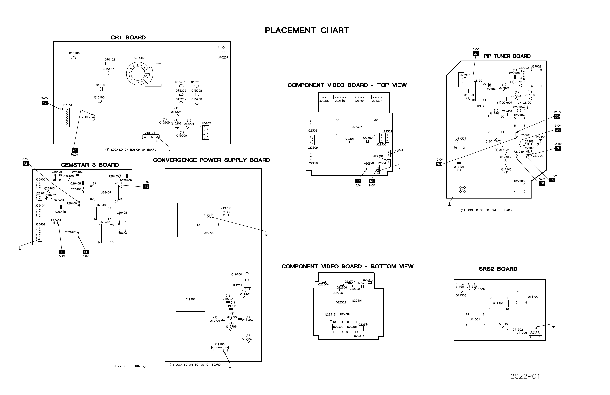
Placement Chart ..................................... 1
Safety Precautions .................................. 1
Schematic Component Location ............8
Schematic Notes ..................................... 5
Schematics
PF GOLD 18
Test Equipment....................................... 6
INDEXINDEX
INDEX
INDEXINDEX
Audio ...............................................7
Component Video............................ 8
CRT (Red, Green & Blue) .............. 2
CRT Convergence ...........................4
CRT Convergence Power Supply.... 3
Gemstar 3 ........................................ 6
Main Tuner ...................................... 5
PIP ...................................................4
PIP Tuner Board.............................. 5
Power Supply ..................................3
System Control ................................6
Television ........................................ 2
PF GOLD 18
Technical Service Data
RCARCA
RCA
RCARCA
Model P52939YX1 (Chassis PTK195S1B_S1)Model P52939YX1 (Chassis PTK195S1B_S1)
Model P52939YX1 (Chassis PTK195S1B_S1)
Model P52939YX1 (Chassis PTK195S1B_S1)Model P52939YX1 (Chassis PTK195S1B_S1)
Representative Model
ff
or seror ser
f
or ser
ff
or seror ser
Essential coEssential co
Essential co
Essential coEssential co
vicing a televicing a tele
vicing a tele
vicing a televicing a tele
veravera
gg
vera
veravera
vision receivervision receiver
vision receiver
vision receivervision receiver
ee
g
e
gg
ee
......
...
......
PF GOLD 18
HIGH HIGH
VV
OLOL
TT
AA
HIGH
V
HIGH HIGH
VV
Apply 120VAC. Use the remote to set customer controls for normal operation. Momentarily short BC14901
base of Q14901 to ground. The receiver should lose raster and sound. If receiver does not lose raster and
sound, the shutdown circuit should be repaired. To resume normal operation, remove AC power for
approximately 30 seconds and then turn the receiver on.
The listing of any available replacement part herein in no case constitutes a recommendation, warranty, or guarantee by
SAMS Technical Publishing as to the quality and suitability of such replacement part. The numbers of the listed parts have
been compiled from information furnished to SAMS Technical Publishing by the manufacturers of the specific type of
replacement part listed.
Reproduction or use, without express permission, of editorial or pictorial content, in any manner, is prohibited. No patent
liability is assumed with respect to the use of the information contained herein.
© 2002
5436 West 78th Street
Indianapolis, IN 46268-4149
Printed in the United States of America 5 4 3 2 1
PP
aa
gg
e 1e 1
P
PP
PF GOLD 18 PF GOLD 18
a
g
e 1
PF GOLD 18
aa
gg
e 1e 1
PF GOLD 18 PF GOLD 18
GE SHUTDOGE SHUTDO
OL
T
A
GE SHUTDO
OLOL
TT
AA
GE SHUTDOGE SHUTDO
WN WN
WN
WN WN
TESTTEST
TEST
TESTTEST
02PT02022
UPC
HERE
MODEL P52939YX1 (CHASSIS PTK195S1B_S1)MODEL P52939YX1 (CHASSIS PTK195S1B_S1)
MODEL P52939YX1 (CHASSIS PTK195S1B_S1)MODEL P52939YX1 (CHASSIS PTK195S1B_S1)
MODEL P52939YX1 (CHASSIS PTK195S1B_S1)
RCARCA
RCARCA
RCA
For Supplier AdFor Supplier Ad
For Supplier Ad
For Supplier AdFor Supplier Ad
See PHOSee PHO
See PHO
See PHOSee PHO
TT
T
TT
OFOF
OF
OFOF
AA
CT AnnCT Ann
A
CT Ann
AA
CT AnnCT Ann
dress,dress,
dress,
dress,dress,
ual Indeual Inde
ual Inde
ual Indeual Inde
xx
x
xx
ScSc
hematicshematics
•
Sc
hematics
ScSc
hematicshematics
Component locationsComponent locations
•
Component locations
Component locationsComponent locations
PP
arar
ts listts list
•
P
ar
ts list
PP
arar
ts listts list
Coverage includes these additional models and chassis:
ModelsModels
Models
ModelsModels
P52939YX2 PTK195S16B_S1
P52939YX3 PTK195S2B_S2
P61960YX1 PTK195Y06T_Y
DECEMBER DECEMBER
DECEMBER
DECEMBER DECEMBER
2002 PF GOLD 18 2002 PF GOLD 18
2002 PF GOLD 18
2002 PF GOLD 18 2002 PF GOLD 18
ChassisChassis
Chassis
ChassisChassis
PP
aa
gg
e 1e 1
P
PP
PF GOLD 18 PF GOLD 18
a
g
e 1
PF GOLD 18
aa
gg
e 1e 1
PF GOLD 18 PF GOLD 18

PF GOLD 18 PPF GOLD 18 P
PF GOLD 18 P
PF GOLD 18 PPF GOLD 18 P
aa
gg
e 1e 1
a
g
e 1
aa
gg
e 1e 1

RCA MODEL P52939YX1 (CHASSIS PTK195S1B_S1)
RCA MODEL P52939YX1 (CHASSIS PTK195S1B_S1)RCA MODEL P52939YX1 (CHASSIS PTK195S1B_S1)
RCA MODEL P52939YX1 (CHASSIS PTK195S1B_S1)RCA MODEL P52939YX1 (CHASSIS PTK195S1B_S1)
PF GOLD 18 PPF GOLD 18 P
PF GOLD 18 P
PF GOLD 18 PPF GOLD 18 P
aa
gg
e 1e 1
a
g
e 1
aa
gg
e 1e 1

PP
aa
gg
e 2e 2
P
PP
PF GOLD 18 PF GOLD 18
a
g
e 2
PF GOLD 18
aa
gg
e 2e 2
PF GOLD 18 PF GOLD 18

PF GOLD 18 PPF GOLD 18 P
PF GOLD 18 P
PF GOLD 18 PPF GOLD 18 P
aa
gg
e 2e 2
a
g
e 2
aa
gg
e 2e 2

PP
aa
gg
e 2e 2
P
PP
PF GOLD 18 PF GOLD 18
a
g
e 2
PF GOLD 18
aa
gg
e 2e 2
PF GOLD 18 PF GOLD 18

RCA MODEL P52939YX1 (CHASSIS PTK195S1B_S1)
RCA MODEL P52939YX1 (CHASSIS PTK195S1B_S1)RCA MODEL P52939YX1 (CHASSIS PTK195S1B_S1)
RCA MODEL P52939YX1 (CHASSIS PTK195S1B_S1)RCA MODEL P52939YX1 (CHASSIS PTK195S1B_S1)
PF GOLD 18 PPF GOLD 18 P
PF GOLD 18 P
PF GOLD 18 PPF GOLD 18 P
aa
gg
e 2e 2
a
g
e 2
aa
gg
e 2e 2

PP
aa
gg
e 3e 3
P
PP
PF GOLD 18 PF GOLD 18
a
g
e 3
PF GOLD 18
aa
gg
e 3e 3
PF GOLD 18 PF GOLD 18

PF GOLD 18 PPF GOLD 18 P
PF GOLD 18 P
PF GOLD 18 PPF GOLD 18 P
aa
gg
e 3e 3
a
g
e 3
aa
gg
e 3e 3

PP
aa
gg
e 3e 3
P
PP
PF GOLD 18 PF GOLD 18
a
g
e 3
PF GOLD 18
aa
gg
e 3e 3
PF GOLD 18 PF GOLD 18
PFGOLD 18 PPFGOLD 18 P
PFGOLD 18 P
PFGOLD 18 PPFGOLD 18 P
aa
gg
e 3e 3
a
g
e 3
aa
gg
e 3e 3

MISCELLANEOUS ADJUSTMENTS
SERSER
VICE MENUVICE MENU
SER
VICE MENU
SERSER
VICE MENUVICE MENU
To access the service menu, turn the receiver on, press the menu button on
the front panel, and hold it down while pressing the power button. While
holding down the menu button, release the power button and press the
volume + button. The screen will display a one line menu, on the left the
parameter P0, and on the right the value of that parameter V0. Release
buttons. Adjustments are made by selecting the proper parameter and
changing the value of that parameter. To change the parameter number use
channel up and down buttons. To adjust the current value of that parameter
use volume + and - buttons. To access and change any of the adjustments,
the proper parameter pass number must be entered. This information is
listed at the beginning of the alignment. When these parameters are
modified, the T-Chip and the corresponding EEPROM are updated. All
service adjustments are bus controlled, except focus and screen.
NOTE: In order to adjust the RF AGC, audio or video levels, tuner, PIP, or
stereo circuits, the Chipper Check hardware and software must be used.
This can be purchased from Thomson Electronics.
SERSER
VICE ADJUSTMENT PARAMETERSVICE ADJUSTMENT PARAMETERS
SER
VICE ADJUSTMENT PARAMETERS
SERSER
VICE ADJUSTMENT PARAMETERSVICE ADJUSTMENT PARAMETERS
PP
arameterarameter
P
arameter
PP
arameterarameter
No.No.
No.
No.No.
0 Pass number for service adjustment Must set to 76 - May not advance until value is set to 76.
1 Error Code 1 0 0 - 255 Displays the first error detected. Set to 0 before exiting.
2 Error Code 2 0 0 - 255 Displays the second error detected. Set to 0 before exiting.
3 Error Code 3 0 0 - 255 Displays the last error detected. Set to 0 before exiting.
4 Horizontal Phase 10 0 - 15 Tune in a crosshatch pattern, adjust to center the pattern on
5 EW DC (Width) 16 0 - 31 Tune in a crosshatch pattern, adjust for slight horizontal overscan.
6 EW Amplitude 8 0 - 15 Set value to 8.
7 EW Tilt 8 0 - 15 Set value to 8.
8 Top Corner Pin Correction 2 0 - 7 Set value to 2.
9 Bottom Corner Pin Correction 2 0 - 7 Set value to 2.
10 Vertical DC 33 0 - 63 Tune in a crosshatch pattern, adjust to center vertically.
11 Vertical Size 84 0 - 127 Tune in a crosshatch pattern, adjust for slight vertical overscan.
12 Vertical Countdown Mode 0 0 - 3 Set value to 0. ( 0 = Standard, 1 = Non-Standard, 2 = 50Hz,
13 Red Bias 30 0 - 127 Press menu button on the TV set for setup line.
14 Green Bias 15 0 - 127 Press menu button on the TV set for setup line.
15 Blue Bias 34 0 - 127 Press menu button on the TV set for setup line.
16 Red Drive 41 0 - 63 17 Green Drive 33 0 - 63 18 Blue Drive 32 0 - 63 19 Gemstar Horizontal OSD Position 166 0 - 255 Set value to 166.
20 Gemstar Vertical OSD Position 68 0 - 255 Set value to 68.
21 Gemstar PIP Horizontal Position 40 0 - 255 Set value to 40.
22 Gemstar PIP Vertical Position 43 0 - 255 Set value to 43.
23 Gemstar PIP Window Vertical Size 3 0 - 13 Set value to 3.
PP
arameter Namearameter Name
P
arameter Name
PP
arameter Namearameter Name
parameters.
On SetOn Set
On Set
On SetOn Set
VV
aluealue
V
alue
VV
aluealue
DIGITDIGIT
AL CONVERGENCEAL CONVERGENCE
DIGIT
AL CONVERGENCE
DIGITDIGIT
AL CONVERGENCEAL CONVERGENCE
Enter service mode. Using the remote control from a position that enables
you to have clear details of the picture, press the VOL UP button to advance
the Value range to “80”, then press CH UP.
The incoming Video signal will be blanked out and a crosshatch pattern
with a small yellow centered cursor will be displayed. The volume and
channel buttons will move the cursor up, down, left, and right in single
steps. The four navigation move buttons on the remote will adjust the
selected color at the cursor point. The green color will be stationery, the red
and blue colors are to be adjusted to the green. To select between the Red,
or Blue adjustment press the INFO or DISPLAY button on the remote
control. When INFO button is pressed the cursor color change from yellow
to cyan indicating that the color to be adjusted is the blue instead of the red.
Pressing the power button on the remote will end and save changes to the
DigiCon EEPROM, and the screen will return to normal signal reception.
NOTE: Before making any changes in the service adjustments its recommended to keep a record of the on set values.
VV
aluealue
V
alue
VV
aluealue
RangRang
ee
e
ee
CommentComment
Comment
CommentComment
See Error Codes Chart.
See Error Codes Chart.
See Error Codes Chart.
the screen.
3 = 48Hz )
Rang
RangRang
RCA MODEL P52939YX1 (CHASSIS PTK195S1B_S1)
RCA MODEL P52939YX1 (CHASSIS PTK195S1B_S1)RCA MODEL P52939YX1 (CHASSIS PTK195S1B_S1)
RCA MODEL P52939YX1 (CHASSIS PTK195S1B_S1)RCA MODEL P52939YX1 (CHASSIS PTK195S1B_S1)
PF GOLD 18 PPF GOLD 18 P
PF GOLD 18 P
PF GOLD 18 PPF GOLD 18 P
aa
gg
e 3e 3
a
g
e 3
aa
gg
e 3e 3
 Loading...