

RCA MR14400, MG14200 Diagram

MR20400
A-PDF MERGER DEMOA-PDF MERGER DEMO
FEB/02
Television
Basic Service Data
Alignment Procedures..................................................................................................... 6
Block Diagrams............................................................................................................... 29
General Information and Safety...................................................................................... 1
IC Pin Descriptions ........................................................................................................ 21
Parental Control.............................................................................................................. 12
Replacement Partlist....................................................................................................... 38
Schematics
Mono .......................................................................................................................... 59
Stereo (MR20411 only) ............................................................................................... 60
Troubleshooting.............................................................................................................. 13
Voltage Charts ................................................................................................................ 34
Waveforms...................................................................................................................... 31
MR20400
Additional Models:
MG14200, MG20200,
MR14400 & MR20411
Latin America After Sales
Indianapolis, IN 46290 U.S.A.
SERVICE DATA INDEX
Page
Number
CAUTION: Modification or repair of this unit by unauthorized persons is a direct violation of FCC Rules Part 68.216 and could
result in risk of electric shock. You are urged to contact a qualified factory authorized service facility for repairs.
SAFETY NOTICE
USE ISOLATION TRANSFORMER WHEN SERVICING
Components having special safety characteristics are identified by a ( ) on schematics and on the parts list in this Service Data and its bulletins.
Before servicing this instrument, it is important that the service technician read and follow the "Safety Precautions" in the Basic Service Data.
First Edition - First Printing
Copyright 2002 - Thomson multimedia Inc.
Printed in U.S.A. - Trademark(s)
®
Registered - Marca(s) Registrada(s)
MR20400

6
ALIGNMENT INSTRUCTION SUBINDEX
Page
Number
1. SERVICE MODE ADJUSTMENTS...................................................................................7
2. ASSEMBLY ADJUSTMENTS............................................................................................7
ALIGNMENT INSTRUCTION
7
1. SERVICE MODE ADJUSTEMNTS
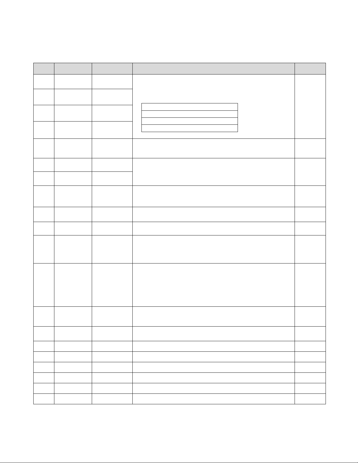
Follw the steps below whenever service adjustment is required. See Table-A and Table-B to determine if service adjustments are
required.
1) How to enter the service mode using the user remote control.
• Turn the set on.
• dierect the remote control to the reception window of TV.
• Push buttons of remote control in sequence as follosws.
1 → MUTE → INFO → MUTE
• Then, the screen will appear as follows.
• Using the channel up or channel down button, select the item you wish to adjust.
(The color of selected item turns into the red.)
2) How to memorize the adjusted values in the service mode.
• Must press DISPLAY button the state which the screen is displaying each of service menus after all adjustments are completed
each of all service menu.
Table-A : Adjust the values of sevice mode when a part is replaced.
ALIGNMENT INSTRUCTIONS
S2 SCRN
V.=02h RCCR = 00h
S5 IFC
S6 GEO
S8 W/B
S9 DP
S12 FACT
S7 PTRN NORMAL
S10 SOUND
PART
REPLACED
I701
(U-COM)
Data is stored in I703
Initial setting values are written from I701.
Adjusting Items
Adjust items related to picture tube only.(White Balance adjustment)
S 5 RFAGCD
S 6 H.PHASE/V.POSI/V.SIZE
S 8 RD/BD/RB/GB/BB
S 9 Subbrightness
O
I101
(MAIN)
I703
(EEPROM)
CRT
O
O
O
ADJUSTMENT
NECESSARY UNNECESSARY
NOTES
8
MODE
ADJUSTMENT ITEMS
DATA
S 2 Screen Adjustment
Auto RF AGC
Video Level (VIDEOL)
RF AGC Delay (RFAGCD)
FM Level (FM. LEV)
AGC Point
Horizontal Phase (H.PHASE)
Vertical Position (V.POSI)
Vertical Size (V.SIZE)
NO SD POWER OFF
Vertical S-Correction (V SC)
Vertical Linearity (V LIN)
Internal Black
Internal 100% White
Internal 60% White
Internal Cross Pattern
Red Drive (RD)
Green Drive (GD)
Blue Drive (BD)
Red Bias (RB)
Green Bias (GB)
Blue Bias (BB)
Subbrightness
Contrast
Tint
Color
Sharp
ATT
SPECTRAL
WIDEBAND
Forwarding Mode
-
7
*
8
3.75
*
*
*
YES
0
18
-
-
-
-
*
10
*
*
160
*
64
10
27
15
15
9
28
22
–
-
-
0~7
0~63
0~31
0~31
0~63
0~127
0~31
0~31
-
-
-
-
0~127
0~15
0~127
0~255
0~255
0~255
0~127
0~27
0~77
0~27
0~30
0~15
0~63
0~63
–
Must be set to 7
Align RF AGC threshold
Must be set to 8
Select AGC reference voltage
Align sync to flyback pulse, using internal cross Pattern(S7)
Align vertical DC bias, using internal cross pattern(S7)
Align vertical amplitude, using internal cross pattern(S7)
Must be set to 0
Must be set to 18
Display internal BLACK pattern
Display internal 100% WHITE
Display internal 60% WHITE
Display internal CROSS pattern
Align RED OUT AC level
Must be set to 10
Align BLUE OUT AC level
Align RED OUT DC level
Must be set to 160
Align BLUE OUT DC level
Align common RGB DC level
Must be set to 15
Must be set to 9
Factory Initialization
INITIAL
RANGE
REMARKS
S 5
S 6
S 7
S 8
S 9
S 10
S 12
* Indicates the items with different settings each of sets
2. ASSEMBLY ADJUSTMENTS
1) SCREEN ADJUSTMENT (S2)
• Enter the service mode and select service adjustment S2.
• You cna see the one horizontal line on the screen.
• Adjust the Screen Control Volume (Iocated on FBT) so that the horizontal line onscreen may be disappeared.
• Press the volume up or down button to exit in the screen adjustment mode.
IN THE SCREEN ADJUSTMENT MODE, DONT PRESS OTHER BUTTONS EXCEPT VOLUME UP OR
DOWN BUTTON.
Table-B
ALIGNMENT INSTRUCTIONS
NOTE
9
2) FOCUS ADJUSTMENT
• Turn in a local station and adjust the Focus Control knob (located on FBT) for best picture details at high light condition.
3) RF AGC DELAY ADJUSTMENT (S5)
• Receive a good local channel.
• Enter the service mode and select service adjustment S5.
• You can see the OSD as shown in below.
• Select RFAGCD item, press the volume up or down button until noise or beat in picture disappears.
• Press the INFO button to memorize the data.
4) GEOMETRIC ADJUSTMENTS (S6)
• Enter the service mode and select service adjustment S7.
• Whenever you select the “S7” using the volume up or down button, the screen is changing like this.
NORMAL BLACK WHITE100 WHITE60 CROSS
• Using the volume up or down button, select internal cross pattern.
• Select service adjustment S6
• You can see the OSD as shown in below.
4)-1. Horizontal Position Adjustment
• Select H.PHASE item, adjust H.PHASE data value to obtain proper horizontal centering toe internal cross pattern at the left and
right of the screen.
4)-2. Vertical Position Adjustment
• Select V.POSI item, adjust V.POSI data value to center the raster properly on thescreen.
ALIGNMENT INSTRUCTIONS
(Continued)
IF CONTROL
AUTO RFAGC START
VIDEOL 7
RFAGCD 10
FM.LEV 8
AGC POINT 3.75
A/D VALUE:8DH
…
†
MOVE œ √ ADJUST RECALL:SET
GEOMETRY
H. PHASE 20
V. POSI 29
V. SIZE 70
NO SD POWER OFF YES
V SC 0
V LIN 18
…
†
MOVE œ √ ADJUST RECALL:SET

10
4)-3. Vertical Size Adjustment
• Select “V.SIZE” item, adjust “V.SIZE” data value to proper vertical size as follows.
5) WHITE BALANCE ADJUSTMENT(S8)
• Receive a good local channel.
• Enter the service mode and select service adjustment S8.
• You can see the OSD as shown in below.
• Using volume up or volume down, adjust service adjustment data of RD/GD/BD and RB/GB/BB untiol a good gray scale with nor-
mal whites is obtained.
• Press the INFO button to memorize the data.
6) DIGITAL PRESET(D.P) ADJUSTMENTS(S9)
SUBBRIGHTNESS ADJUSTMENT
• Receive a good local channel.
• Enter the service mode and select service adjustment S9.
• You can see the OSD as shoown in below.
ALIGNMENT INSTRUCTIONS
(Continued)
RD 58
GD 10
BD 65
RB 105
GB 160
BB 100
…
†
MOVE œ √ ADJUST RECALL:SET
D.P.
SUB BRIGHTNESS 64
CONTRAST 10
TINT 27
COLOR 15
SHARP 15
…
†
MOVE œ √ ADJUST RECALL:SET

11
• Select Subbrightness item, adjust Subbrightness data value to obtain normal brightness level.
• Press the INFO button to memorize the data.
CONTRAST
• Fixed value = 10
TINT
• Fixed value = 27
COLOR
• Fixed value = 15
SHARP
• Fixed value = 15
7) FACTORY OUTGOING MODE (S12:FACT)
• If you select the S12, then the set becomes factory outgoing status.
• You can see the OSD “outgoing OK”
ALIGNMENT INSTRUCTIONS
(Continued)
29
BLOCK DIAGRAM (MR14400/20400, MG14200/20200): MONO
A.MUTE(H)
5
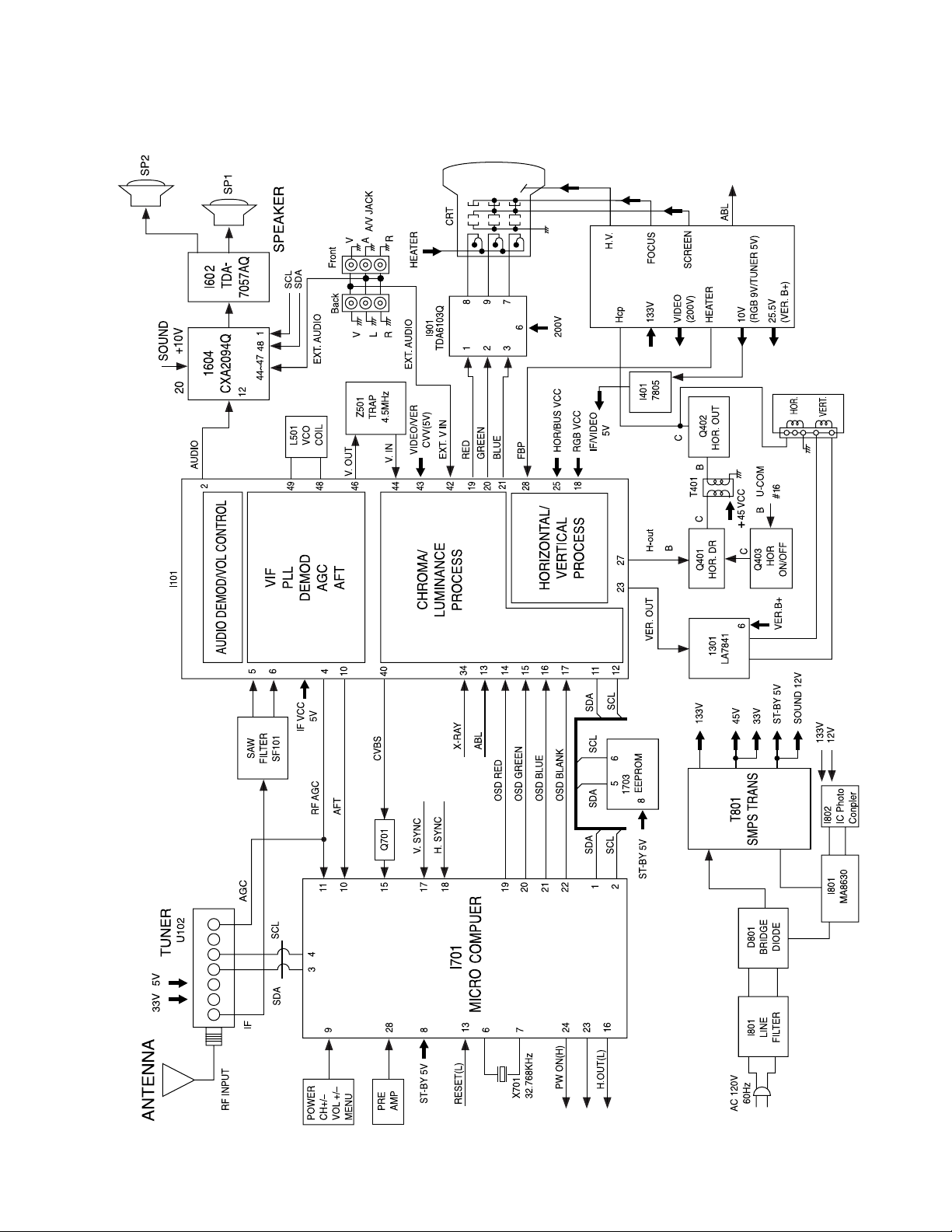
30
BLOCK DIAGRAM (MR20411): STEREO
A.MUTE(H)
5
2
CAUTION: Do not attempt to modify this product in any way. Unauthorized
modifications will not only void the warranty, but may lead to your being liable
for any resulting property damage or user injury.
Service work should be performed only afer you are thoroughly familiar with all
of the following safety checks and servicing guidelines. To do otherwise, increases the risk of potential hazards and injury to the user.
SAFETY CHECKS
After the orginal service problem has been corrected, a check should be made of
the follwoing:
SUBJECT : FIRE & SHOCK HAZARD
1. Be sure that all components are positioned in such a way as to aboid possibility
of adjacent component shorts. This is especially important on those chassis
which are transported to and from the repair shop.
2. Never release a repair unless all protective devices such as insulators, barriers,
covers, shields, strain reliefs, and other hardware have been reinstalled per
original design.
3. Soldering must be inspected to discover possible cold solder joints, frayed
leads, damaged insulation (including a.c. cord), solder splahes or sharp solder
points. Be certain to remove all loose foreigh particals.
4. Check for physical evidence of damage or deterioration to parts and compo-
nents, and replace if necessary follw original layout, lead length and dress.
5. No leads or components should touch a receiving tube or a resistor rated at 1
watt or more. Lead tension around protruding metal surfaces must be avoided.
6. All critical components such as fuses, flameproof resistors, capacitor, etc. must
be replaced with exact factory types. Do not use replacement components other
than those specified or make unrecommended circuit modifications.
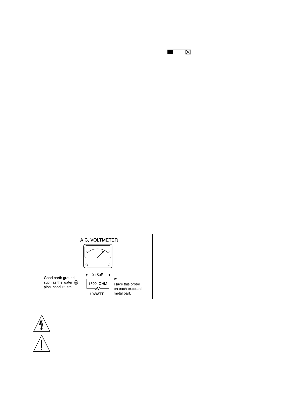
7. after re-assembly of the set always perform an A.C. leakage test on all exposed
metallic parts of the cabinet, (the channel selector knob, antenna terminals,
handle and screws) to be sure the set is safe to operate without danger of electrical shock. Do not use a line isolation transformer during this test. Use an
A.C. voltmeter, having 5000 ohms per volt or more sensitivity, in the following
manner: connect a 1500 ohm 10 watt resistor, paralleled by a 15 mfd. 150V
A.C. type capacitor between a known good earth ground (9water pipe, conduit,
etc.) and the exposed metallic part, one at a time. Measure the A.C. voltage
across the combination of 1500 ohm resistor and 0.15 MFD capacitor. Reverse
the A.C. plug and repeat A.C. voltage measurements for each exposed metallic
part. Voltage measured must not exceed 0.75 volts. R.M.S. This corresponds to
0.5 milliamp A.C Any value exceeding this limit constitutes a potential shock
hazard and must be corrected immediately.
GRAPHCI SYMBOLS:
The lightning flash with arrowhead symbol, within an equilateral triangle, is intended to alert the service personnel to the persence of
uninsulated “dangerous voltage’ that may be of sufficienty magnitude to constitute a risk of electric shock.
The exclamation point within an equilateral triangle is intended to
alert the service personnel to the presence of important safety information in service literature.
Fuse symbol is printed on pcb adjacent to the fuse, with
“RISK OF FIRE REPLACE FUSE AS MARKED”. The
symbol is explained in the service manual with the following wording or equivalent..
“CAUTION: FOR CONTINUED PROTECTION AGAINST FIRE
HAZARD, REPLACE ONLY WIHT SAME TYPE (4A, 12V)” and
“ATTENTION: AFIN D’ASSU UNE PROTECTION PERMANENTE CONTRE LES RISQUES D’INCENDIE, REMPLACER
UNIQUEMENT PAR UN FUSIBLE DE MEME TYPE ET DE “4A,
125V
”.
SUBJECT: X-RADIATION
1. Be sure procedures and instructions to all service personnel cover the subject of
X-rays in current T.V. receivers is the picture tube. However, this tube does not
emit X-rays when the high voltage is at the factory specified level. The proper
value is given in the applicalbe schematic. Operation at higher voltages may
cause a failure of the picture tube or high voltage supply and, under certain circumstances, may produce radiation in excess of desirable levels.
2. Only factory specified C.R.T. anode connectors must be used.
Degaussing shields also serve as X-rays shield in color sets. Always re-install
them.
3. It is essential that the serviceman has available and accurate and reliable high
voltage meter. The calibration of the meter should be checked perio-dically
against a reference standard. Such as the one available at your distributor.
4. When the high voltage circuitry is operating properly there is no possibility of
an X-radiation problem. Every tice a color chassis is serviced, the brightness
should be run up and down while monitoring the high voltage with a meter to
be certain that the high voltage does not exceed the specified value and that it is
regulating correctly. We suggest that you and your service organization review
test procedures so that voltage regulation is always cecked as a standard servicing procedure. And that the high voltage reading be recorded on each customer’s invoice.
5. When troubleshooting and making test measurements in a receiver with a
problem of excessive high voltage, avoid being unnecessarily close to the picture tub eand the high voltage compartment.
Do not operat the chassis longer than is necessary to locate the cause of excessive voltage.
6. Refer to HV, B+and Shutdown adjustment procedures described in the appropriate schematic and diagrams(where used).
SUBJECT: IMPLOSION
1. All direct viewed picture tubes are equipped with an integral implosion protection system, but care should be taken to avoid damage during installation.
Avoid scratching the tube. If scratched, replace it.
2. Use only recommended factory replacement tubes.
SUBJECT: TIPS ON PROPER INSTALLATION
1. Never install any receiver in closed-in recess, cubbyhole or closely fitting shelf
space over, or close to heat duct, or in the path of heated air flow.
2. Avoid conditions of high humidity such as: Outdoor patio installations where
dew is a factor, Near steam radiators where steam leakage is a factor, etc.
3. Avoid placement where draperies may obstruct rear venting. The customer
should also avoid the use of decorative scarves or other coverings which might
obstruct ventilation.
4. Wall and shelf mounted installations using a commercial mounting kit, must
follow the factory approved mounting instructions. A receiver mounted to a
sheif or platform must retain its original feet(or the equivalent thickness in
spacers) to provide adequate are flow across the bolts or screws used for fasteners must not touch and parts or wiring. Perform leakage test on customized
installations.
5. Caution customers against the mounting of a receiver on sloping shelf or a tilted position, unless the receiver is properly secured.
6. A receiver on a roll-about cart should be stable on its mounting to the cart.
Caution the customer on the hazards of trying to roll a cart with small casters
across thresholds or deep pile carpets.
7. Caution customers against the use of a cart or stand which has not been listed
by underwriters laboratories, in. For use with their specific model of telvision
receiver or generically approved for use with T.V.’s of the same or larger
screen size.
PRODUCT SAFETY SERVICING GUIDELINES FOR COLOR TELEVISION RECEIVERS
SPECIFICATIONS
MODELS
MR14400/MG14200 MR20400/MG20200 MR20411
ITEMS
TV STANDARD NTSC-M
POWER INPUT AC120V 60HZ
POWER CONSUMPTION 55W 68W
TUNING SYSTEM Frequency Synthesizer (FS) Tuning System
TUNING RANGES VHF : 2~13 (12)
UHF : 14~69 (56)
CATV : 1~125 (125)
SOUND OUTPUT 1.3W x 1.3W
SPEAKER 3W 8 ohm x 2
ANTENNA INPUT IMPEDANCE 75 ohm Unbalanced
AUXILIARY INPUT TERMINAL Front : Video, Audio, Earphone
Rear : Video, Audio
INTERMEDIATE FREQUENCIES Picture IF Carrier Frequency: 45.75 MHz
Sound IF Carrier Frequency: 41. 25 MHz
Color Sub-Carrier Frequency: 42.17 MHz
REMOTE CONTROL MR* : CRK10A / MG* : CRK20A
SPECIAL FUNCTION 3-Language OSD
With CAPTION
Wake-up/Off Time
Sleep Timer
Power Restore
DIMENSIONS 440(W) x 340(H) x 372(D)mm 580(W) x 442(H) x 463(D)
SCREEN SIZE Diagonal
Horizontal
Vertical
WEIGHT 9.45Kg(net) / 11Kg(tot) 17.5Kg(net) / 20.1Kg(tot)
335.4mm
280.8mm
210.6mm
480.0mm
404.4mm
303.3mm
Front : Video, Audio L/R
Rear : Video, Audio L/R
- 3 -
4
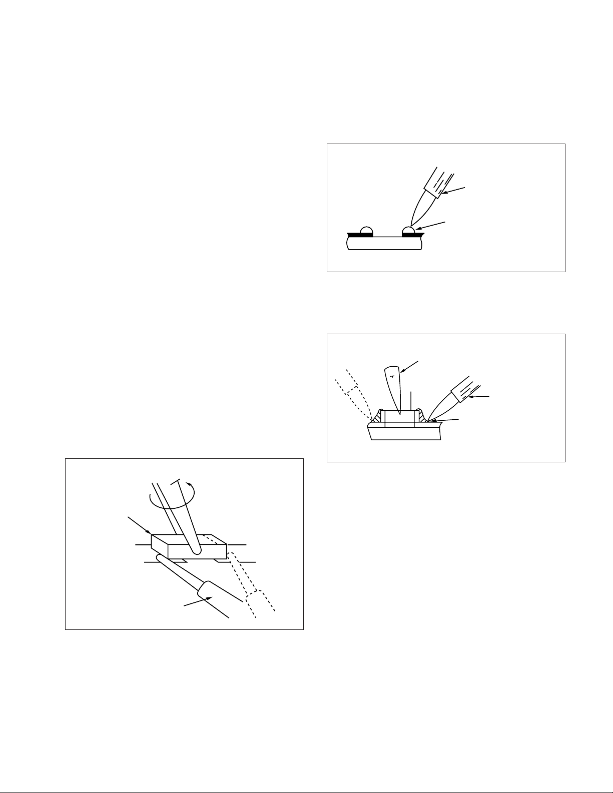
Replacement Procedure for Leadless (Chip) Removal
The following procedures are recommended for the replacement
of the leadless components used in this unit.
1. Preparation for replacement
a. Soldering Iron
Use a pencil-type soldering iron that uses less than 30
watts.
b. Solder
Eutectic solder (Tin 63%, Lead 37%) is recommended.
c. Soldering time
Do not apply heat more than 4 seconds.
d. Preheating
Leadless capacitor must be preheated before installation.
(130 degrees - 150 degrees C).
Note:
a. Leadless component must not be reused after removal.
b. Excessive mechanical stress and rubbing of the compo-
nent electrode must be avoided.
2. Removing the leadless component (Resistors, Capacitors)
Grasp the leadless component body with tweezers and alternately apply heat to both electrodes. When the solder on both
electrodes is melted, remove leadless component with a twisting motion.
Note:
a. Do not attempt to lift the component off the board until
the component is completely disconnected from the
board by a twisting action.
b. Take care not to break the copper foil on printed circuit
board.
Fig. 1-Leadless Component Removal
3. Installing the Leadless Component
a. Presolder the contact points of the circuit board.
Fig. 2- Leadless Component Installation
b. Press the part downward with tweezers and solder both
electrodes as shown below.
Fig. 3- Leadless Component Installation
Note:
Do not glue the replacement leadless component to the cir-
cuit board.
Soldering lron
Presolder
LEADLESS COMPONENT REMOVAL
Chip
Tweezers
Soldering lron
Tweezers
Soldering lron
Solder
5
A A/D Analog/Digital
ABL Auto Beam Limit
AFT AutomaticFine Tuning
AGC Automatic Gain Control
AMP Amplifier
B BB Blue Bias
BD Blue Drive
C CVS Composite Video signal
D DP Digital Preset
DY Deflection Yoke
F F ACT Fatory
FBT Fly Back Transfomer
FM Frequecny Modulation
FM. LEV FM Level
G GB Green Bias
GD Green Drive
GEO Geometry
GND Ground
H H.PHASE Horizontal Phase
H.SYC Horizontal Sync.
HOR Horizontal
I IF Intermediate Frequency
IF Intermediate Frequency
IFC Intermediate Frequency Control
O OCP Over Current Protector
OSC Oscillator
OSD On-Screen Display
P PRTN Parental
RB Red Bias
RRD Red Drive
RF Radio Frequency
S SA W Surface Acoustic Wave
SCL Serial Clock
SCRN Screen
SD Syn. Detection
SDA Serial Date
SIF Sound Intermediate Frequency
ST-BY Stand by
T T-CLOCK Tuner Clock
T-DATA Tuner Data
V V LIN Vertical Linearity
V SC Vertical S Correction
V.POSI V ertical Position
V.SIZE Vertical Size
V.SYC Vertical Syn.
VCC Voltage Supply
VCO Voltage Controlled Oscillator
VDD Voltage Supply
VER Vertical
W W/B Wite/Balance
ABBREVIATIONS

21
IC DESCRIPTION
IC DESCRIPTION SUBINDEX
Page
Number
1. IC DESCRIPTION (U-COM(I701)).................................................................................22
2. IC DESCRIPTION (DTC814-(I101))...............................................................................23
22
U-COM(I701)
IC DESCRIPTION
X’TAL:32.768 KHz
23
I101
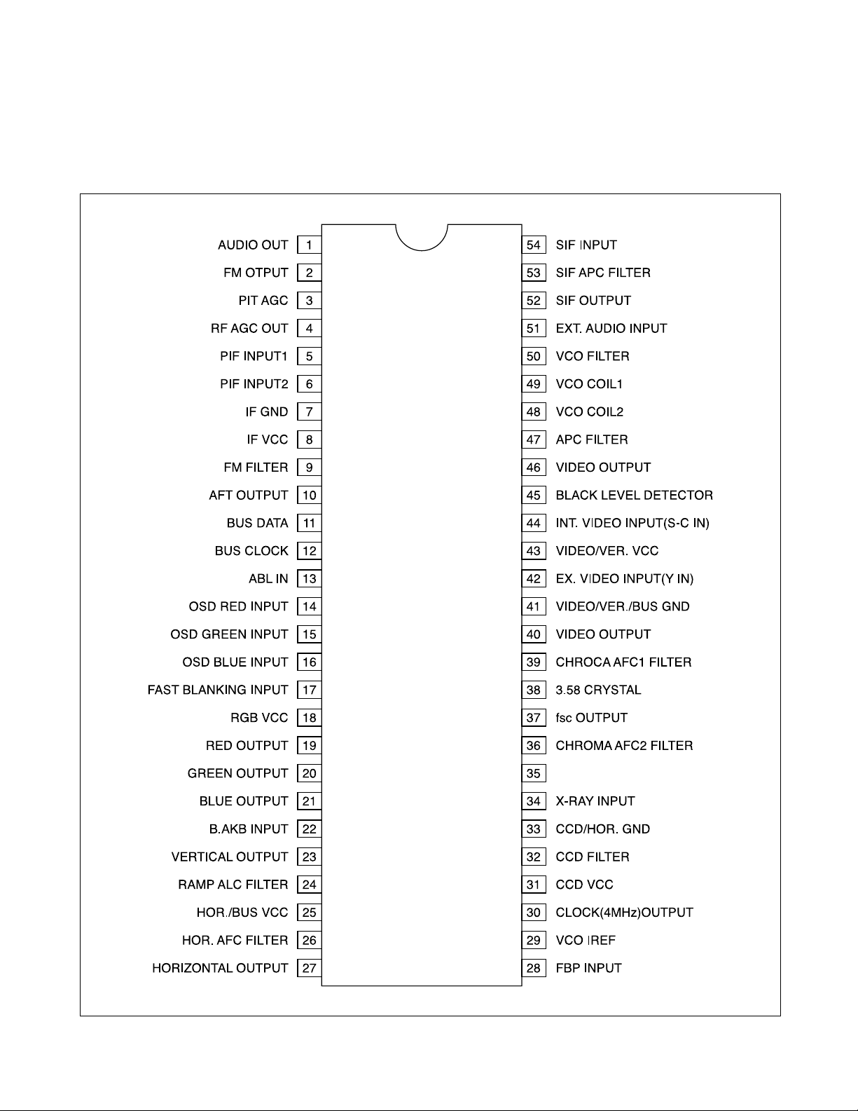
DCT814(LA76814): IC VIDEO PROCESSOR
IC DESCRIPTION
(Continued)

24
1. Abstract.
This specification is 1-Tuner Mono Model for North/South America, CCD 1-Chip MICOM LC863228A.
lt is developing software specification for tuning only NTSC
2. H/W Outline.
1) ROM : 28,672 x 8bits. tsc
: 15,872 x 8bits for CGROM.
2) RAM: 512 x 8bits.
: 352 x 9bits. (for CRT Display)
3) OSD Function.
• Screen Display. : 36 characters x 16 lines.(by software)
• RAM : 352 words. (9 bits per word)
Display area. : 36 words. x 8 lines.
1st control area. : 8 words. x 8 lines.
• Characters.
244 patterns programmable.
Up to 244 kinds of 16 x 17 dot characters.
Up to 244 kinds of 8 x 9 dot characters.
or
Up to 244 kinds of 16 x 32 dot characters used 16K bytes.
• Various characters attributes.
Character colors. : 16 colors
Character background colors. : 16 colors
Fringe / shadow colors. : 16 colors
Full screen colors. : 16 colors
Rounding.
Underline.
ltalic character.(slanting)
• Attribute can be changed without spacing.
• Vertical display start line number can be set for each row independently. (Row can be overlapped.)
• Horizontal display start position can be set for each row independently.
• Different display modes can be set for each row independently.
Caption and Text mode/OSD mode 1/OSD mode 2 (Quarter size)/ Simplified graphic mode.
• Ten character sizes.
Horiz. x Vert. = (1x1), (1x2), (2x2), (2x4), (0.5x0.5)
(1.5x1), (1.5x2), (3x2) (3x4), (0.75x0.5)
• Shuttering and scrolling on each row.
3. System Feature.
1) The system for TV tuning is Frequency Synthesis type.
2) Closed Captions function is interior designed.
IC DESCRIPTION
(Continued)

25
3) On Screen displays function is interior designed.
4) Package. : 36 PIN SDIP.
5) Tuner (Pre-scaler.) : 1
2
C Bus.
/PLL IC : TAU 6014-S(SIEMENS).
6) Remocon. : The IC of Transmission (MITSUBISHI M50560)
7) E
2
PROM. : 24C08(I2C Bus) Apply one byte Read/Write mode.
8) 6-Local Key. : A/D Input Control. (Power, Ch Up/Down, Vol Up/Down, Menu)
9) Option S/W : Port Input Option Check.
10) IF/V/C/D IC : DTC814 (LA76814)
4. Function.
1) C. C. D. function.
- A section of C. C. D. operates FCC based specification.
2) C. C. D. controlled function.
- Closed Caption Mode. (Off
↔
C1
↔
C2
↔
T1
↔
T2
↔
Off)
- CC On Mute. (Off
↔
C1
↔
C2
↔
Off)
- closed Caption is prior to CC On Mute.
3) Tuning Function.
- 1
2
C Bus.
- PLL IC Interface.
- FS 181 Channel (AIR 2-69CH, CABLE 1-125CH)
- AFT Operation(Fine Tuning) -2.5Fn +2.5MHz
- AIR/CABLE (STD, HRC, IRC). Only Cable 5,6Ch is that AFT range is cover over broad-band. -2.5MHzFn+3.5MHz..
- Memorize Channels. (If a channel is broadcasting, the channel is memorized.)
- Direct Tuning (09KEY)
- Channel Up/Down. (Memorized Channels)
➝
The Ch Up/Down buttons on the Remocon and on the front panel are same
function.
- Search Channel Up/Down. (If No-Memory or only 1CH is Memory)
- Channel Memory. (ADD/DELETE)
- Channel Review Function.
- Last Channel Memory Function.
4) OSD Function.
- In Line (Video) Mode, Things(Items) that is concerned with Air and Cable disappear in the Menu.
- Channel, AV display.
- Small & Graphic ICON Menu.
- Volume / Picture control
➝
12C Bus Control
5) The Others Function.
- Video/Audio Mute function.
-If a Channel is no signal, after 15 minutes is Auto-Power Off function.
IC DESCRIPTION
(Continued)
26
- Auto Power On Function. (Power Restore function in the Special Menu)
- Heat Run Function. --- OSD White Back-Ground
- Sleep Timer.
- Wake Up Time Function.
- Off Time Function.
- Remote Reception & Control.
- Auto Tint. (Option)
- Power Restore
- Input(TV/Line) Controlled function. (Option)
- Reception. (Air/Cable : Factory Inlitial Condition)
- Blue Background. (Option)
- 3-Language (North America : ENG/SPA/FRA, South America : ENG/SPA/POR).
- E
2
PROM Interface (12C Bus Control)
- CH 6 TRAP Function. (IS-31)
- PLL IC Band Data. (Control Byte 2
➝
P3~P0)
VHF L : 1
VHF H : 2
CH6 TRAP : 5 (IS-31) AIR (Cable) CH 6 Only
UHF :8
5. The Table of Opteon and Schedule.
IC DESCRIPTION
(Continued)
Model Name PIN OPTION Application Reference
CN-001N
#30
#32
#33
#34
#35
#36
Auto Tint
Blue Back
Prison
Mono/Stereo
Caption
TV Only
O
O
O
O
X
O
6
Total Sum
– Low (DC-0V) : On (Auto Tint)
– High (DC-5V) : Off
– Low (DC-0V) : Blue Back
– High (DC-5V) : No Blue Back
– Low (DC-0V) : Normal
– High (DC-5V) : Prison
– Low (DC-0V) : Mono
– High (DC-5V) : Stereo
– No Use
– No Use
– Low (DC-0V) : TV/Video
– High (DC–5V) : TV/Only
– Use. (No Use.
27
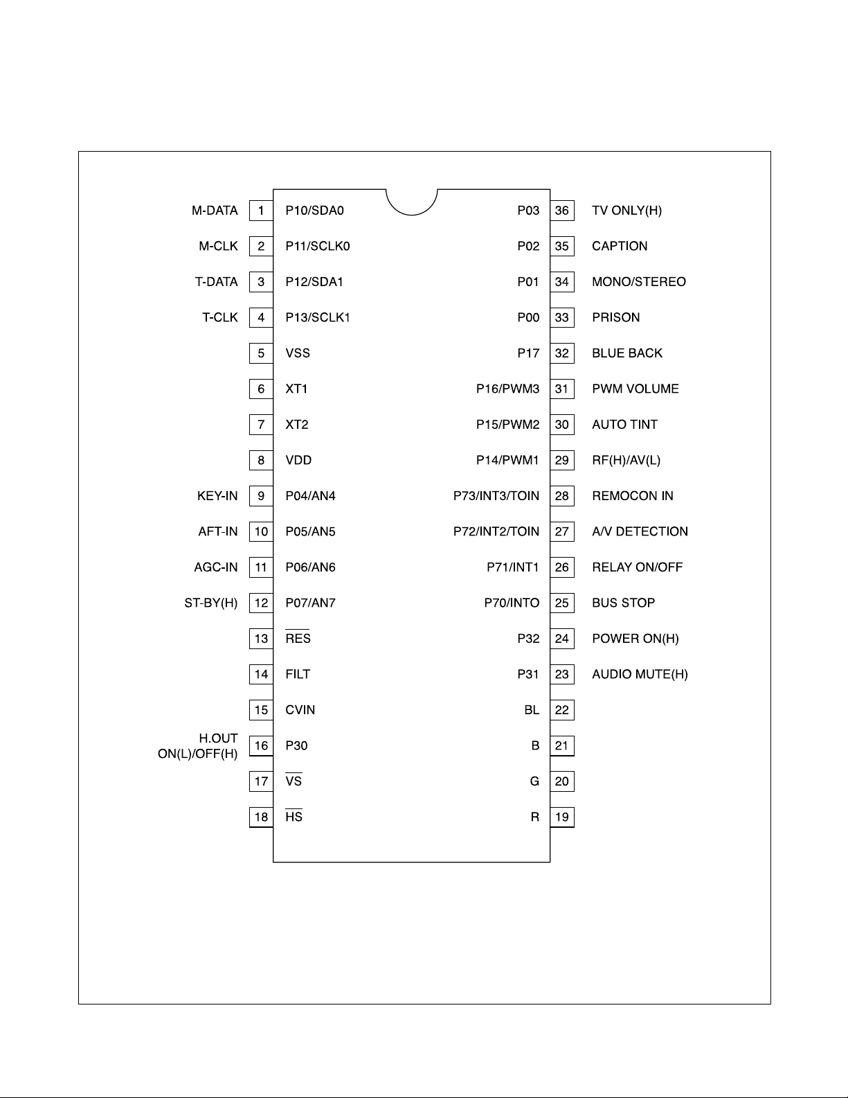
6. Pin description
PIN Terminal Name Explanation Remarks
1
2
3
4
5
6
7
8
9
10
11
12
13
14
15
16
17
18
19
20
ROM Data Main
IC Data
ROM CLK
Main IC CLK
Tuner Data
Tuner CLK
GND
XT1
XT2
VDD
KEY-IN
AFT-IN
AGC-IN
ST-BY(H)
/RES
Filter
CVSB IN
TV/VID
/VS
/HS
R
G
– 6 – bit input/output port
– Input/output can be Specified for each bit
– Other function.
– GND
– Negative power supply.
– It uses 32.768KHz X-TAL.
– 10 pin is input terminal for crystal oscillator.
– 11 pin is output terminal for crystal oscillator.
– +5V (±0.5V)
– Positive power supply.
– Power, Ch up/down, Vol up/down, Menu
– Dc value that comes from the 10 pin of LA76810/14
– Connect this port to AGC of Tuner
– Default Voltage : 3.75V
– Variable Voltage : 3.25V, 3.5V, 4.0V
– Use only japan Model.
– This port uses when is Stand - By status
– Condition : Input AC Power On
– Power off : ‘High (DC 5V)’ Output. (Red)
– Power on : ‘Low (DC 0V)’ Output.
– Reset terminal.
– Active Low
– Filter terminal for PLL
– Output terminal
– Video signal input terminal
– TV Mode : ‘High” Line(Video) Mode : ‘Low’
– Vertical synchronization signal input terminal
– Horizental synchronization signal input terminal
– Red output terminal of RGB image
– Green output terminal of RGB image
P10/SDA0
P11/SCLK0
P12/SDA1
P13/SCLK1
VSS
XT1
XT2
VDD
P04/AN4
P05/AN5
P06/AN6
P07/AN7
/FES
FILT
CVIN
P01
/VS
/HS
R
G
P10 IIC0 data I/O
P11 IIC0 clock output.
P12 IIC1 data I/O
P13 IIC1 clock output.
IC DESCRIPTION
(Continued)

28
21
22
23
24
25
26
27
28
29
30
31
32
33
34
35
36
B
BL
Audio Mute
Power On
Bus Stop
Relay On/Off
A/V Detection
Remocon In
RF(H)/AV(L)
AUTO TINT
PWM VOLUME
BLUE BACK
PRISON
MONO/STEREO
CAPTION
TV ONLY(H)
–Blue output terminal of RGB image
– Fast blanking control signal
– Switch TV image Signal and caption / OSD image signal
– Output terminal
– Use only ‘read data’ of LA76814/10
– Use when does power off/on
– Power off: Output ‘Low(DC 0V)
– Power on: Output ‘High(DC 5V)
– No Use
– Relay On/Off Terminal
– Detect port of Front A/V
– Input of Remocon Signal
– High: RF only mode
– Low: RF/AV mode
– Low (DC-0V) : On(Auto Tint)
– High (DC-5V) : Off
– Use only to control Sound of Stereo mode
– High (DC-5V) : No Blue Back
– Low (DC-0V) : Blue Back
– Low (DC-0V) : Normal
– High (DC-5V) : Prison
– Low (DC-0V) : Mono
– High (DC-5V) : Stereo
– No Use
– Low (DC-0V) : TV/Video
– High (DC-5V) : TV Only
B
BL
P31
P32
P70/INT0
P71/INT1
P72/INT2
P73/INT3
P14/PWM1
P15/PWM2
P16/PWM3
P17
P00
P01
P02
P03
Output form and existence of pull- up resistor for every port can be specified for each bit.
At port 1, “Programable pull- up resistor provided” when specifing either COOS or N- ch open drain output.
Port status in reset.
Teriminal I/O Pull- up resistor status at selection pull- up option.
Port 0 I Pull- up resistor OFF, ON after reset release.
Port 1 I Programmable pull- resistor OFF.
PIN Terminal Name Explanation
IC DESCRIPTION
(Continued)
12
If user forget Parental Control Password as follows.
1. CHANGE THE PASSWORD.
• Turn the set on.
• Direct the remote control to the reception window of your TV/VCR
• Using the MENU buttons, select the Special menu.
• Using the the channel up (
…) or down (†) buttons, select Prental Control.
• Using the volume up (
√), set the password Menu.
• Push buttons of remote control in sequence as follows.
2
➝ 2➝ 1➝
1
• Parental control password is reset.
• Using the 0~9 buttons, enter the password.
• Using the 0~9 buttons, repeat the password.
2. RESET THE PASSWORD
• Turn the set on.
• Direct the remote control to the reception window of your TV/VCR.
• Push buttons of remote control in sequence as follows.
1
➝
MUTE
➝
INFO
➝
MUTE
• Then, the screen will appear as follows.
• Using the channel up (
…) or down (†) buttons, select S12 FACT.
Press the volume up (
√) button, the set becomes factory outgoing status.
• Parental control password is reset.
• Using the MENU buttons, select the parental control menu, set the new password.
PARENTAL CONTROL PASSWORD SETTINGS
Closed Caption : OFF
CC on Mute : OFF
Power Restore : OFF
√ Parental Control
Special
Select √ Enter ■ Exit
œ√
Enter the Password
# # # #
Parental control
[0 - 9] : Adjust ■ Exit
Enter New Password
– – – –
Parental control
[0 - 9] : Adjust ■ Exit
Repeat the Password
# # # #
Parental control
[0 - 9] : Adjust ■ Exit
FIELE SVC
S2 SCRN
V.=02h RCCR=00h
S5 IFC
S6 GEO
S8 W/B
S9 DP
S12 FACT
S7 PTRN NORMAL
√ S10 SOUND

REPLACEMENT PARTS MG14200
(See Product Safety Note on first page of this parts list)
Symbol SymbolStock StockDrawing DrawingDescription Description
MG14200
ELECTRICAL
A001 N / A 4859814191 PCB MAIN 246X246 S1B
C101 194251 CEXF1H109V CAP LYTC 1UF 50V
C102 186763 CEXF1C101V CAP LYTC 100UF 16V
C103 232287 CEXF1H339V CAP LYTC 3.3UF 50V
C104 238799 CMXM2A333J CAP POLY .033UF J 100V
C105 230779 CEXF1C471V CAP LYTC 470UF 16V
C106 194251 CEXF1H109V CAP LYTC 1UF 50V
C107 250886 CEXF1H228V CAP LYTC .22UF 50V
C212 194557 CEXF1H100V CAP LYTC 10UF 50V
C235 250887 CEXD1H229F CAP LYTC 2.2MF 50V
C301 149164 CMXM2A103J CAP POLY .01UF J 100V
C302 178991 CEXF1H479V CAP LYTC 4.7UF 50V
C303 194557 CEXF1H100V CAP LYTC 10UF 50V
C305 244959 CEXF1H101V CAP LYTC 100MK 50V
C307 230784 CXSL2H100D CAPCD 10PF D SL 500V
C308 230781 CMXM2A104J CAP POLY 0.1UF 100V
C310 201162 CEXF1E102V CAP LYTC 1000UF 25V
C311 230782 CEXD1H229Q CAP LYTC 2.2UF 50V
C401 150872 CCXB2H102K CAPCD 1000PF K 500V
C403 250888 CCYB2H103K CAPCD .01MF 500V
C404 T0000625 CMYH3C722H CAP MYLAR 1.6KV BUP
7200PF
C405 230785 CEXF2C109V CAP LYTC 1UF 160V
C406 T0000626 CMYE2D434J CAP MYLAR 200V PU 0.43MF
C408 230787 CEXF1H220V CAP LYTC 22UF 50V
C410 185180 CEXF2E100V CAP LYTC 10UF 250V
C411 194557 CEXF1H100V CAP LYTC 10UF 50V
C413 150872 CCXB2H102K CAPCD 1000PF K 500V
C414 230819 CEXF1V471V CAP LYTC 470UF 35V
C415 178835 CEXF1C102V CAP LYTC 1000UF 16V
C418 230781 CMXM2A104J CAP POLY 0.1UF 100V
C451 186763 CEXF1C101V CAP LYTC 100UF 16V
C452 189978 CEXF1C221V CAP LYTC 220UF 16V
C501 C / P CMXL1J105J C MYLAR 63V MEU 1MF
C502 230779 CEXF1C471V CAP LYTC 470UF 16V
C507 C / P CMXM2A224J C MYLAR 100V 0.22MF
C508 C / P CMXM2A224J C MYLAR 100V 0.22MF
C509 194251 CEXF1H109V CAP LYTC 1UF 50V
C510 230779 CEXF1C471V CAP LYTC 470UF 16V
C511 238799 CMXM2A333J CAP POLY .033UF J 100V
C512 197379 CEXF1H108V CAP LYTC .1UF 50V
C513 194251 CEXF1H109V CAP LYTC 1UF 50V
C514 230779 CEXF1C471V CAP LYTC 470UF 16V
C516 192315 CEXF1H229V CAP LYTC 2.2UF 50V
C517 C / P CMXB1H473J C MYLAR 50V 0.047MF
C518 200226 CEXF1H478V CAP LYTC .47UF 50V
C519 200226 CEXF1H478V CAP LYTC .47UF 50V
C520 194251 CEXF1H109V CAP LYTC 1UF 50V
C525 194251 CEXF1H109V CAP LYTC 1UF 50V
C555 194251 CEXF1H109V CAP LYTC 1UF 50V
C575 189978 CEXF1C221V CAP LYTC 220UF 16V
C601 149164 CMXM2A103J CAP POLY .01UF J 100V
C602 178835 CEXF1C102V CAP LYTC 1000UF 16V
C603 197379 CEXF1H108V CAP LYTC .1UF 50V
C604 230783 CEXF1H470V CAP LYTC 47UF 50V
C613 197379 CEXF1H108V CAP LYTC .1UF 50V
C614 230783 CEXF1H470V CAP LYTC 47UF 50V
C615 230779 CEXF1C471V CAP LYTC 470UF 16V
C634 178991 CEXF1H479V CAP LYTC 4.7UF 50V
C646 230779 CEXF1C471V CAP LYTC 470UF 16V
C701 230783 CEXF1H470V CAP LYTC 47UF 50V
C702 189978 CEXF1C221V CAP LYTC 220UF 16V
C703 194251 CEXF1H109V CAP LYTC 1UF 50V
C704 192315 CEXF1H229V CAP LYTC 2.2UF 50V
C705 194251 CEXF1H109V CAP LYTC 1UF 50V
C780 194251 CEXF1H109V CAP LYTC 1UF 50V
C801 244963 CL1UC3104M CAP 0.01UF WORLD AC250V
C802 250893 CMYH3C332J CAP POLY 3300PF J 1.6KV
C804 250894 CEYN2D331P CAP LYTC 330MF 200V
C807 149164 CMXM2A103J CAP POLY .01UF J 100V
C809 250895 CMXM2A102J CAP POLY 1000PF J 100V
C810 230802 CCXB2H222K CAPCD 2200PF K 500V
C811 230802 CCXB2H222K CAPCD 2200PF K 500V
C812 178835 CEXF1C102V CAP LYTC 1000UF 16V
C813 250896 CCXB3A221K CAPCD 220PF K 1KV
C814 168725 CEXF2C101V CAP LYTC 100UF 160V
C818 186763 CEXF1C101V CAP LYTC 100UF 16V
C819 178991 CEXF1H479V CAP LYTC 4.7UF 50V
C820 168725 CEXF2C101V CAP LYTC 100UF 160V
C845 244993 CEXF2A100V CAP LYTC 100V RSS10MF
C850 230781 CMXM2A104J CAP POLY 0.1UF 100V
C876 186763 CEXF1C101V CAP LYTC 100UF 16V
C880 244956 CH1BFE222M CAP 2200PF SD AC400V
C912 T0000611 CH1BEE472M CAP CERA AC U/C/V 2.5KV
4700PF
CC151 230568 HCBK103KCA CAPCC .01UF K 50V
CC152 230568 HCBK103KCA CAPCC .01UF K 50V
CC153 230568 HCBK103KCA CAPCC .01UF K 50V
CC154 230568 HCBK103KCA CAPCC .01UF K 50V
CC155 230568 HCBK103KCA CAPCC .01UF K 50V
CC528 230580 HCBK102KCA CAPCC 1000PF K 50V
CC551 242170 HCQK101JCA CAPCC 100PF J 50V
CC552 242170 HCQK101JCA CAPCC 100PF J 50V
CC556 230566 HCQK809DCA CAPCC 8PF D 50V
CC560 230568 HCBK103KCA CAPCC .01UF K 50V
CC562 194440 HCQK180JCA CAPCC 18PF J 50V
CC567 250900 HCQK181JCA CAPCC 180PF 50V
CC568 230568 HCBK103KCA CAPCC .01UF K 50V
CC569 230568 HCBK103KCA CAPCC .01UF K 50V
CC570 230563 HCFK104ZCA CAPCC .1UF Z 50V
CC571 230563 HCFK104ZCA CAPCC .1UF Z 50V
CC573 230563 HCFK104ZCA CAPCC .1UF Z 50V
CC575 230580 HCBK102KCA CAPCC 1000PF K 50V
CC580 249102 HCBK152KCA CAPCC 1500PF K X7R 50V
CC612 230563 HCFK104ZCA CAPCC .1UF Z 50V
CC662 235530 HCBK153KCA CAPCC .015UF K 50V
CC752 194440 HCQK180JCA CAPCC 18PF J 50V
CC753 194440 HCQK180JCA CAPCC 18PF J 50V
CC754 230568 HCBK103KCA CAPCC .01UF K 50V
CC755 230568 HCBK103KCA CAPCC .01UF K 50V
CC756 250901 HCQK221JCA CAPCC 220PF J 50V
CC757 250902 HCBK333KCA CAPCC .033MF X7R K 50V
CC758 242170 HCQK101JCA CAPCC 100PF J 50V
C / P - Common Part (Obtain through local parts store)
N / A - Not available as a service part
38

REPLACEMENT PARTS (Continued) MG14200
(See Product Safety Note on first page of this parts list)
Symbol SymbolStock StockDrawing DrawingDescription Description
CC759 242170 HCQK101JCA CAPCC 100PF J 50V
CC760 242170 HCQK101JCA CAPCC 100PF J 50V
CC768 242170 HCQK101JCA CAPCC 100PF J 50V
CC780 230568 HCBK103KCA CAPCC .01UF K 50V
CC796 230568 HCBK103KCA CAPCC .01UF K 50V
CC900 230580 HCBK102KCA CAPCC 1000PF K 50V
CC902 C / P HCQK271JCA C CHIP CERA 50V CH 270PF
CC903 C / P HCQK271JCA C CHIP CERA 50V CH 270PF
CC904 C / P HCQK271JCA C CHIP CERA 50V CH 270PF
D101 244976 DUZ33B---- DIODE ZENER UZ-33B
D102 232282 DUZ5R1B--- DIODE ZENER UZ-5.1B
D221 198589 D1N4148--- DIODE
D301 C / P D1N4004S-- DIODE 1N4004
D311 250904 DBZX55C62- DIODE ZENER
D312 241930 85801065GY CAP .65 TIN COATING
D401 250909 D1N4937G-- DIODE 1N4937G
D405 250909 D1N4937G-- DIODE 1N4937G
D406 250909 D1N4937G-- DIODE 1N4937G
D407 250909 D1N4937G-- DIODE 1N4937G
D408 250909 D1N4937G-- DIODE 1N4937G
D409 198589 D1N4148--- DIODE
D501 198589 D1N4148--- DIODE
D502 198589 D1N4148--- DIODE
D503 232283 DUZ9R1BM-- DIODE ZENER
D504 198589 D1N4148--- DIODE
D505 232283 DUZ9R1BM-- DIODE ZENER
D541 198589 D1N4148--- DIODE
D571 198589 D1N4148--- DIODE
D572 198589 D1N4148--- DIODE
D573 198589 D1N4148--- DIODE
D574 198589 D1N4148--- DIODE
D701 198589 D1N4148--- DIODE
D703 250910 DLH2PR---- DIODE LED
D704 244977 DUZ3R9B--- DIODE ZENER UZ-3.9B
D772 232284 DUZ5R6BM-- DIODE ZENER
D773 232284 DUZ5R6BM-- DIODE ZENER
D774 232284 DUZ5R6BM-- DIODE ZENER
D776 232284 DUZ5R6BM-- DIODE ZENER
D790 198589 D1N4148--- DIODE
D801 T0000612 DPBS208GUF DIODE BRIDGE
PBS208GU-CA
D802 250909 D1N4937G-- DIODE 1N4937G
D807 244974 DRGP15J--- DIODE RGP15J
D812 232284 DUZ5R6BM-- DIODE ZENER
D813 250909 D1N4937G-- DIODE 1N4937G
D824 T0000613 DZY160---- DIODE ZENER ZY160
D841 250909 D1N4937G-- DIODE 1N4937G
D851 250913 DUZ8R2BM-- DIODE ZENER
F801 250916 5F1GB4021L FUSE 4A 125V
F801A 230817 4857415001 CLIP FUSE
F801B 230817 4857415001 CLIP FUSE
I101 250917 1DCT814B-- IC
I301 245000 1LA7841--- IC VERTICAL LA7841
I301 N / A PTC2SW7101 HEAT SINK ASS`Y
I301A 244986 4857027101 HEATSINK
I301B 251119 7174300811 SCREW
I401 250918 1K1A7805P1 IC REGULATOR
I601 244225 1TDA7267-- IC TDA7267
I602 244225 1TDA7267-- IC TDA7267
I703 238808 124LC04B-- IC
I801 250920 1MA8630--- IC POWER
I802 244997 1LTV817C-- IC PHOTO COUPLER
LTV-817C
I803 250921 1DP133---- IC
IL701 T0000614 1KRT50---- IC PREAMP KRT50
JC701 231850 HRFT000-CA RES CCF 1/10W 5% 0R
JC702 231850 HRFT000-CA RES CCF 1/10W 5% 0R
JC703 231850 HRFT000-CA RES CCF 1/10W 5% 0R
JC704 231850 HRFT000-CA RES CCF 1/10W 5% 0R
JP02 T0000624 4859109950 JACK PIN BOARD
PH-JB-9710A
JP03 245004 4859109150 JACK PIN BOARD
L111 230865 58C5580019 COIL CHOKE
L112 T0000615 5CPZ569K02 COIL PEAKING 5.6UH
L501 250926 58N0000042 COIL
L502 250927 5CPZ470K04 COIL
L533 230828 5CPZ150K02 COIL 15UH
L601 250928 58CX430599 COIL
L701 230832 5CPZ220K02 COIL 22UH
L801 250929 5PLF24A1-- FILTER
L805 250928 58CX430599 COIL
L807 250930 5MC0000100 COIL
L811 250930 5MC0000100 COIL
L841 250930 5MC0000100 COIL
L901 253217 5CPX221J-- COIL PEAKING 220UH
P401 230836 4859240020 CONNECTOR
P501 T0000627 4850708N11 CONNECTOR
BIC-08T-25T+C-20T
P601 230837 485923162S CONNECTOR
P602 230837 485923162S CONNECTOR
P801 230838 4859242220 CONNECTOR
P802 250933 4850701S09 CONNECTOR
P802A 250934 4859262120 CONNECTOR WAFER
PA601 T0000616 4850703S51 CONNECTOR
YH025-03+35098
PA602 251135 4850703S52 CONNECTOR
PWC1 T0000618 4859902710 CORD POWER ASM
Q201 250941 TKSC945CY- TRANSISTOR KSC945C-Y
Q401 250942 TKSC2330Y- TRANSISTOR KSC2330Y
Q402 T0000630 TKSC5386-- TRANSISTOR KSC5386
Q402A N / A PTH2SW7200 HEAT SINK ASS`Y TKSC5386
Q403 250941 TKSC945CY- TRANSISTOR KSC945C-Y
Q404 250941 TKSC945CY- TRANSISTOR KSC945C-Y
Q570 229733 TKTA1266Y- TRANSISTOR
Q575 250943 TKTA1275Y- TRANSISTOR KTA1275Y
Q701 250941 TKSC945CY- TRANSISTOR KSC945C-Y
Q702 250941 TKSC945CY- TRANSISTOR KSC945C-Y
Q703 250941 TKSC945CY- TRANSISTOR KSC945C-Y
Q704 229733 TKTA1266Y- TRANSISTOR
Q707 250941 TKSC945CY- TRANSISTOR KSC945C-Y
Q804 250943 TKTA1275Y- TRANSISTOR KTA1275Y
Q805 230843 TKTC3205Y- TRANSISTOR
Q851 250941 TKSC945CY- TRANSISTOR KSC945C-Y
Q902 230851 TKTC3229-- TRANSISTOR
Q903 230851 TKTC3229-- TRANSISTOR
Q904 230851 TKTC3229-- TRANSISTOR
C / P - Common Part (Obtain through local parts store)
N / A - Not available as a service part
39

REPLACEMENT PARTS (Continued) MG14200
(See Product Safety Note on first page of this parts list)
Symbol SymbolStock StockDrawing DrawingDescription Description
R165 250944 RD-4Z472J- RES CF 1/4W 4.7K
R227 250945 RD-4Z102J- RES CF 1/4W J 1K
R301 250952 RN01B471JS RES MF 1W J 470R
R302 250952 RN01B471JS RES MF 1W J 470R
R303 250953 RN01B129JS RES MF 1W J 1.2R
R305 250954 RN01B331JS RES MF 1W J 330R
R351 250955 RD-4Z682J- RES CF 1/4W 6.8K
R352 250956 RN-4Z1603F RES MF 1/4W 160K
R353 250957 RN-4Z1502F RES MF 1/4W 15K
R359 250958 RD-4Z273J- RES CF 1/4W J 27K
R360 250959 RD-4Z333J- RES CF 1/4W J 33K
R361 250960 RD-4Z222J- RES CF 1/4W J 2.2K
R362 250961 RD-4Z113J- RES CF 1/4W J 11K
R401 250944 RD-4Z472J- RES CF 1/4W 4.7K
R403 250963 RN01B562JS RES MF 1W J 5.6K
R405 250964 RD-2Z751J- RES CF 1/2W J 750R
R411 250965 RN01B229JS RES MF 1W J 2.2R
R412 C / P RN01B369JS RES MF 1W 3.6 OHM
R413 250965 RN01B229JS RES MF 1W J 2.2R
R414 250965 RN01B229JS RES MF 1W J 2.2R
R416 250967 RD-2Z121J- RES CF 1/2W J 120R
R417 250968 RD-4Z302J- RES CF 1/4W J 3K
R418 250969 RN02B150JS RES MF 2W J 15R
R420 250970 RN02B620JS RES MF 2W J 62R
R451 251138 RD-4Z153J- RES CF 1/4W J 15K
R452 250961 RD-4Z113J- RES CF 1/4W J 11K
R501 250972 RD-2Z151J- RES CF 1/2W J 150R
R502 250972 RD-2Z151J- RES CF 1/2W J 150R
R554 250945 RD-4Z102J- RES CF 1/4W J 1K
R569 250973 RD-4Z152J- RES CF 1/4W J 1.5K
R570 250968 RD-4Z302J- RES CF 1/4W J 3K
R579 250945 RD-4Z102J- RES CF 1/4W J 1K
R591 250974 RD-4Z331J- RES CF 1/4W J 330R
R592 250974 RD-4Z331J- RES CF 1/4W J 330R
R593 250974 RD-4Z331J- RES CF 1/4W J 330R
R601 250975 RF01Z688K- RES FUSE 1W K .68R
R602 C / P RD-2Z271J- RES CF 1/2 270 OHM
R604 250955 RD-4Z682J- RES CF 1/4W 6.8K
R703 250977 RD-4Z101J- RES CF 1/4W J 100R
R709 250978 RD-4Z392J- RES CF 1/4W J 3.9K
R743 250944 RD-4Z472J- RES CF 1/4W 4.7K
R744 250979 RD-4Z242J- RES CF 1/4W J 24K
R746 250980 RD-4Z752J- RES CF 1/4W J 7.5K
R747 250981 RD-4Z243J- RES CF 1/4W J 24K
R763 175363 RD-4Z201J- RES CF 1/4W 5% 200R
R776 250982 RD-4Z473J- RES CF 1/4W J 47K
R777 250945 RD-4Z102J- RES CF 1/4W J 1K
R780 184056 RD-4Z471J- RES CF 1/4W 5% 470R
R789 250945 RD-4Z102J- RES CF 1/4W J 1K
R790 250945 RD-4Z102J- RES CF 1/4W J 1K
R796 250944 RD-4Z472J- RES CF 1/4W 4.7K
R801 T0000619 RX07B229JP RES CEMENT 7W 2.2 OHM
R802 250984 RD-4Z205J- RES CF 1/4W J 2M
R804 175363 RD-4Z201J- RES CF 1/4W 5% 200R
R805 250973 RD-4Z152J- RES CF 1/4W J 1.5K
R806 250980 RD-4Z752J- RES CF 1/4W J 7.5K
R808 250945 RD-4Z102J- RES CF 1/4W J 1K
R809 250945 RD-4Z102J- RES CF 1/4W J 1K
R810 250945 RD-4Z102J- RES CF 1/4W J 1K
R814 250985 RS02Z828JS RES MF 2W J .82R
R817 250952 RN01B471JS RES MF 1W J 470R
R818 250986 RD-4Z135J- RES CF 1/4W J 1.3R
R819 250987 RD-4Z561J- RES CF 1/4W J 560R
R820 250978 RD-4Z392J- RES CF 1/4W J 3.9K
R822 250988 RD-4Z363J- RES CF 1/4W J 36K
R835 C / P RD-4Z114J- RES CF 1/4 110K OHM
R851 250944 RD-4Z472J- RES CF 1/4W 4.7K
R854 C / P RD-4Z244J- RES CF 1/4 240K OHM
R855 C / P RD-4Z510J- R CARBON FILM 1/4 51 OHM
R856 C / P RD-4Z241J- R CARBON FILM 1/4 240 OHM
R881 T0000628 DEC7R0M140 POSISTOR ECPAC7R0M140
R888 250991 RC-2Z565KP RES CF 1/2W K 5.6M
R901 C / P RD-4Z474J- RES CF 1/4 470K OHM
R910 C / P RD-2Z332J- RES CF 1/2 3.3K OHM
R911 C / P RD-2Z332J- RES CF 1/2 3.3K OHM
R912 C / P RD-2Z332J- RES CF 1/2 3.3K OHM
R913 C / P RN02B123JS RES MF 2W 12K OHM
R914 C / P RN02B123JS RES MF 2W 12K OHM
R915 C / P RN02B123JS RES MF 2W 12K OHM
RC105 230602 HRFT153JCA RES CCF 1/10W 5% 15K
RC150 230602 HRFT153JCA RES CCF 1/10W 5% 15K
RC151 230590 HRFT104JCA RES CCF 1/10W 5% 100K
RC154 230592 HRFT473JCA RES CCF 1/10W 5% 47K
RC156 230592 HRFT473JCA RES CCF 1/10W 5% 47K
RC223 235594 HRFT224JCA RES CCF 1/10W 5% 220K
RC224 235594 HRFT224JCA RES CCF 1/10W 5% 220K
RC225 230609 HRFT392JCA RES CCF 1/10W 5% 3.9K
RC226 230589 HRFT101JCA RES CCF 1/10W 5% 100R
RC228 230591 HRFT103JCA RES CCF 1/10W 5% 10K
RC229 230593 HRFT750JCA RES CCF 1/10W 5% 75R
RC453 230591 HRFT103JCA RES CCF 1/10W 5% 10K
RC454 230603 HRFT102JCA RES CCF 1/10W 5% 1K
RC455 230604 HRFT331JCA RES CCF 1/10W 5% 330R
RC503 230595 HRFT752JCA RES CCF 1/10W 5% 7.5K
RC508 230603 HRFT102JCA RES CCF 1/10W 5% 1K
RC509 230603 HRFT102JCA RES CCF 1/10W 5% 1K
RC510 235579 HRFT561JCA RES CCF 1/10W 5% 560R
RC511 235580 HRFT123JCA RES CCF 1/10W 5% 12K
RC525 230603 HRFT102JCA RES CCF 1/10W 5% 1K
RC526 230603 HRFT102JCA RES CCF 1/10W 5% 1K
RC530 235579 HRFT561JCA RES CCF 1/10W 5% 560R
RC531 235579 HRFT561JCA RES CCF 1/10W 5% 560R
RC533 251007 HRFT390JCA RES C 1/10W J 39R
RC541 235581 HRFT682JCA RES CCF 1/10W 5% 6.8K
RC542 230607 HRFT332JCA RES CCF 1/10W 5% 3.3K
RC548 238822 HRFT824JCA RES CCF 1/10W 5% 820K
RC551 230594 HRFT121JCA RES CCF 1/10W 5% 120R
RC556 231850 HRFT000-CA RES CCF 1/10W 5% 0R
RC557 230606 HRFT182JCA RES CCF 1/10W 5% 1.8K
RC558 230591 HRFT103JCA RES CCF 1/10W 5% 10K
RC559 230604 HRFT331JCA RES CCF 1/10W 5% 330R
RC561 235579 HRFT561JCA RES CCF 1/10W 5% 560R
RC562 231176 HRFT914JCA RES CCF 1/10W 5% 910K
RC565 235580 HRFT123JCA RES CCF 1/10W 5% 12K
RC566 235580 HRFT123JCA RES CCF 1/10W 5% 12K
RC567 230591 HRFT103JCA RES CCF 1/10W 5% 10K
C / P - Common Part (Obtain through local parts store)
N / A - Not available as a service part
40

REPLACEMENT PARTS (Continued) MG14200
(See Product Safety Note on first page of this parts list)
Symbol SymbolStock StockDrawing DrawingDescription Description
RC568 251008 HRFT472FCA RES C 1/10W 4.7K
RC570 230591 HRFT103JCA RES CCF 1/10W 5% 10K
RC572 230624 HRFT223JCA RES CCF 1/10W 5% 22K
RC573 230603 HRFT102JCA RES CCF 1/10W 5% 1K
RC576 231850 HRFT000-CA RES CCF 1/10W 5% 0R
RC577 230621 HRFT201JCA RES CCF 1/10W 5% 200R
RC629 230603 HRFT102JCA RES CCF 1/10W 5% 1K
RC630 230590 HRFT104JCA RES CCF 1/10W 5% 100K
RC655 230611 HRFT162JCA RES CCF 1/10W 5% 1.6K
RC701 251009 HRFT220JCA RES C 1/10W J 22R
RC704 230603 HRFT102JCA RES CCF 1/10W 5% 1K
RC705 230599 HRFT472JCA RES CCF 1/10W 5% 4.7K
RC706 230599 HRFT472JCA RES CCF 1/10W 5% 4.7K
RC707 230603 HRFT102JCA RES CCF 1/10W 5% 1K
RC731 230591 HRFT103JCA RES CCF 1/10W 5% 10K
RC732 251006 HRFT132JCA RES C 1/10 J 1.3K
RC733 251006 HRFT132JCA RES C 1/10 J 1.3K
RC734 251006 HRFT132JCA RES C 1/10 J 1.3K
RC735 230603 HRFT102JCA RES CCF 1/10W 5% 1K
RC736 230591 HRFT103JCA RES CCF 1/10W 5% 10K
RC737 230591 HRFT103JCA RES CCF 1/10W 5% 10K
RC738 230618 HRFT471JCA RES CCF 1/10W 5% 470R
RC750 230599 HRFT472JCA RES CCF 1/10W 5% 4.7K
RC751 230618 HRFT471JCA RES CCF 1/10W 5% 470R
RC752 230618 HRFT471JCA RES CCF 1/10W 5% 470R
RC755 230603 HRFT102JCA RES CCF 1/10W 5% 1K
RC756 230603 HRFT102JCA RES CCF 1/10W 5% 1K
RC770 230591 HRFT103JCA RES CCF 1/10W 5% 10K
RC775 230599 HRFT472JCA RES CCF 1/10W 5% 4.7K
RC776 230599 HRFT472JCA RES CCF 1/10W 5% 4.7K
RC778 230591 HRFT103JCA RES CCF 1/10W 5% 10K
RC781 230603 HRFT102JCA RES CCF 1/10W 5% 1K
RC782 230604 HRFT331JCA RES CCF 1/10W 5% 330R
RC783 230599 HRFT472JCA RES CCF 1/10W 5% 4.7K
RC784 241897 HRFT514JCA RES CCF 1/10W 5% 510K
RC786 230603 HRFT102JCA RES CCF 1/10W 5% 1K
RC787 230599 HRFT472JCA RES CCF 1/10W 5% 4.7K
RC788 230599 HRFT472JCA RES CCF 1/10W 5% 4.7K
RC791 230603 HRFT102JCA RES CCF 1/10W 5% 1K
RC792 230603 HRFT102JCA RES CCF 1/10W 5% 1K
RC793 230603 HRFT102JCA RES CCF 1/10W 5% 1K
RC794 230603 HRFT102JCA RES CCF 1/10W 5% 1K
RC799 230591 HRFT103JCA RES CCF 1/10W 5% 10K
RC813 235577 HRFT363JCA RES CCF 1/10W 5% 36K
RC862 235577 HRFT363JCA RES CCF 1/10W 5% 36K
RC913 230594 HRFT121JCA RES CCF 1/10W 5% 120R
RC914 230594 HRFT121JCA RES CCF 1/10W 5% 120R
RC915 230594 HRFT121JCA RES CCF 1/10W 5% 120R
RC917 238931 HRFT241JCA RES CCF 1/10W 5% 240R
RC918 238931 HRFT241JCA RES CCF 1/10W 5% 240R
RC919 238931 HRFT241JCA RES CCF 1/10W 5% 240R
RC923 230618 HRFT471JCA RES CCF 1/10W 5% 470R
RC924 230618 HRFT471JCA RES CCF 1/10W 5% 470R
RC925 230618 HRFT471JCA RES CCF 1/10W 5% 470R
RLY1 251010 5SC0101338 RELAY
RS801 230560 DSVC471D14 VARISTOR
SCT1 T0000621 4859303930 SOCKET CRT ISMG03S
SF101 251012 5PTSF5241P FILTER
SP01 251014 4858314010 SPEAKER 3W 8 OHM
SP01A N / A 7178301211 SCREW TAPTITE 3X12
SP02 251014 4858314010 SPEAKER 3W 8 OHM
SP02A N / A 7178301211 SCREW TAPTITE 3X12
SW701 245027 5S50101090 SWITCH TACT
SW702 245027 5S50101090 SWITCH TACT
SW703 245027 5S50101090 SWITCH TACT
SW704 245027 5S50101090 SWITCH TACT
SW705 245027 5S50101090 SWITCH TACT
SW706 245027 5S50101090 SWITCH TACT
T401 T0000622 50D10A3--- TRANS DRIVE TD-10A3
T402 251015 50H0000198 TRANSFORMER
T801 251016 50M3541T2- TRANSFORMER
U102 T0000623 4859721730 TUNER VARACTOR
DT5-NF20F N
X502 230926 5XEX3R579C CRYSTAL QUARTZ
X701 244972 5XYR03276C CRYSTAL QUARTZ
32.768KHZ
Z501 251020 5PYXT4R5MB FILTER
MECHANICAL/CABINET
CRT1 N / A PTRTPWH394 CRT ASSEMBLY NTSC 14"
M191 N / A 4851944101 BUTTON CTRL
M191A N / A 7178301211 SCREW TAPTITE 3X12
M201 N / A 4852079401 MASK FRONT HIPS GY
M201A 250939 4856013300 SCREW CRT FIXING
M201A N / A 4857820000 CLOTH BLACK CLOTH
M201B N / A 4856215401 WASHER RUBBER CR T1.0
M211 N / A 4852160601 COVER BACK HIPS GY
M211A 250932 7172401612 SCREW 4X16
M211B 250932 7172401612 SCREW 4X16
M561 N / A 4855623101 MARK BRAND ABS BK
M601 N / A 4856013301 SCREW CRT FIXING 30X140
YL
V01 T0000629 58D0000082 COIL YOKE ODY-M1489
V02 N / A 2233030001 PAINT LOCK
V03 N / A 2TC18019BE TAPE CLOTH
T0.18XW19X50M BEIGE
V04 N / A 2224050026 BOND SILICON RTV 122
CARTRIDGE
V05 230771 4850PM001- MAGNET
V06 233666 48A96R004- WEDGE, RUBBER
V901 N / A 48A96314C3 CRT BARE A34KQV42X
ZZ131 232281 58G0000078 COIL DEGAUSSING
ZZ132 N / A 48519A4710 CRT GROUND NET
INCLUDED ACCESSORIES
ZZ100 240961 48BCRK20A- TRANSMITTER REM CRK20A
C / P - Common Part (Obtain through local parts store)
N / A - Not available as a service part
41

REPLACEMENT PARTS (Continued) MG20200
(See Product Safety Note on first page of this parts list)
Symbol SymbolStock StockDrawing DrawingDescription Description
MG20200
ELECTRICAL
A001 N / A 4859814191 PCB MAIN 246X246 S1B
C101 194251 CEXF1H109V CAP LYTC 1UF 50V
C102 186763 CEXF1C101V CAP LYTC 100UF 16V
C103 232287 CEXF1H339V CAP LYTC 3.3UF 50V
C104 238799 CMXM2A333J CAP POLY .033UF J 100V
C105 230779 CEXF1C471V CAP LYTC 470UF 16V
C106 194251 CEXF1H109V CAP LYTC 1UF 50V
C107 250886 CEXF1H228V CAP LYTC .22UF 50V
C212 194557 CEXF1H100V CAP LYTC 10UF 50V
C235 250887 CEXD1H229F CAP LYTC 2.2MF 50V
C301 149164 CMXM2A103J CAP POLY .01UF J 100V
C302 178991 CEXF1H479V CAP LYTC 4.7UF 50V
C303 194557 CEXF1H100V CAP LYTC 10UF 50V
C305 244959 CEXF1H101V CAP LYTC 100MK 50V
C307 230784 CXSL2H100D CAPCD 10PF D SL 500V
C308 230781 CMXM2A104J CAP POLY 0.1UF 100V
C310 201162 CEXF1E102V CAP LYTC 1000UF 25V
C311 230782 CEXD1H229Q CAP LYTC 2.2UF 50V
C401 150872 CCXB2H102K CAPCD 1000PF K 500V
C403 250888 CCYB2H103K CAPCD .01MF 500V
C404 250889 CMYH3C662H CAP POLY 6600PF 1.6KV
C405 230785 CEXF2C109V CAP LYTC 1UF 160V
C406 250890 CMYE2D274J CAP POLY .27MF J 200V
C408 230787 CEXF1H220V CAP LYTC 22UF 50V
C410 185180 CEXF2E100V CAP LYTC 10UF 250V
C411 194557 CEXF1H100V CAP LYTC 10UF 50V
C413 150872 CCXB2H102K CAPCD 1000PF K 500V
C414 230819 CEXF1V471V CAP LYTC 470UF 35V
C415 178835 CEXF1C102V CAP LYTC 1000UF 16V
C418 230781 CMXM2A104J CAP POLY 0.1UF 100V
C451 186763 CEXF1C101V CAP LYTC 100UF 16V
C452 189978 CEXF1C221V CAP LYTC 220UF 16V
C501 C / P CMXL1J105J C MYLAR 63V MEU 1MF
C502 230779 CEXF1C471V CAP LYTC 470UF 16V
C507 C / P CMXM2A224J C MYLAR 100V 0.22MF
C508 C / P CMXM2A224J C MYLAR 100V 0.22MF
C509 194251 CEXF1H109V CAP LYTC 1UF 50V
C510 230779 CEXF1C471V CAP LYTC 470UF 16V
C511 238799 CMXM2A333J CAP POLY .033UF J 100V
C512 197379 CEXF1H108V CAP LYTC .1UF 50V
C513 194251 CEXF1H109V CAP LYTC 1UF 50V
C514 230779 CEXF1C471V CAP LYTC 470UF 16V
C516 192315 CEXF1H229V CAP LYTC 2.2UF 50V
C517 C / P CMXB1H473J C MYLAR 50V 0.047MF
C518 200226 CEXF1H478V CAP LYTC .47UF 50V
C519 200226 CEXF1H478V CAP LYTC .47UF 50V
C520 194251 CEXF1H109V CAP LYTC 1UF 50V
C525 194251 CEXF1H109V CAP LYTC 1UF 50V
C555 194251 CEXF1H109V CAP LYTC 1UF 50V
C575 189978 CEXF1C221V CAP LYTC 220UF 16V
C601 149164 CMXM2A103J CAP POLY .01UF J 100V
C602 178835 CEXF1C102V CAP LYTC 1000UF 16V
C603 197379 CEXF1H108V CAP LYTC .1UF 50V
C604 230783 CEXF1H470V CAP LYTC 47UF 50V
C613 197379 CEXF1H108V CAP LYTC .1UF 50V
C614 230783 CEXF1H470V CAP LYTC 47UF 50V
C615 230779 CEXF1C471V CAP LYTC 470UF 16V
C634 178991 CEXF1H479V CAP LYTC 4.7UF 50V
C646 230779 CEXF1C471V CAP LYTC 470UF 16V
C701 230783 CEXF1H470V CAP LYTC 47UF 50V
C702 189978 CEXF1C221V CAP LYTC 220UF 16V
C703 194251 CEXF1H109V CAP LYTC 1UF 50V
C704 192315 CEXF1H229V CAP LYTC 2.2UF 50V
C705 194251 CEXF1H109V CAP LYTC 1UF 50V
C780 194251 CEXF1H109V CAP LYTC 1UF 50V
C801 244963 CL1UC3104M CAP 0.01UF WORLD AC250V
C802 250893 CMYH3C332J CAP POLY 3300PF J 1.6KV
C804 250894 CEYN2D331P CAP LYTC 330MF 200V
C807 149164 CMXM2A103J CAP POLY .01UF J 100V
C809 250895 CMXM2A102J CAP POLY 1000PF J 100V
C810 230802 CCXB2H222K CAPCD 2200PF K 500V
C811 230802 CCXB2H222K CAPCD 2200PF K 500V
C812 178835 CEXF1C102V CAP LYTC 1000UF 16V
C813 250896 CCXB3A221K CAPCD 220PF K 1KV
C814 168725 CEXF2C101V CAP LYTC 100UF 160V
C818 186763 CEXF1C101V CAP LYTC 100UF 16V
C819 178991 CEXF1H479V CAP LYTC 4.7UF 50V
C820 168725 CEXF2C101V CAP LYTC 100UF 160V
C845 244993 CEXF2A100V CAP LYTC 100V RSS10MF
C850 230781 CMXM2A104J CAP POLY 0.1UF 100V
C876 186763 CEXF1C101V CAP LYTC 100UF 16V
C880 244956 CH1BFE222M CAP 2200PF SD AC400V
C912 T0000611 CH1BEE472M CAP CERA AC U/C/V 2.5KV
4700PF
CC151 230568 HCBK103KCA CAPCC .01UF K 50V
CC152 230568 HCBK103KCA CAPCC .01UF K 50V
CC153 230568 HCBK103KCA CAPCC .01UF K 50V
CC154 230568 HCBK103KCA CAPCC .01UF K 50V
CC155 230568 HCBK103KCA CAPCC .01UF K 50V
CC528 230580 HCBK102KCA CAPCC 1000PF K 50V
CC551 242170 HCQK101JCA CAPCC 100PF J 50V
CC552 242170 HCQK101JCA CAPCC 100PF J 50V
CC556 230566 HCQK809DCA CAPCC 8PF D 50V
CC560 230568 HCBK103KCA CAPCC .01UF K 50V
CC562 194440 HCQK180JCA CAPCC 18PF J 50V
CC567 250900 HCQK181JCA CAPCC 180PF 50V
CC568 230568 HCBK103KCA CAPCC .01UF K 50V
CC569 230568 HCBK103KCA CAPCC .01UF K 50V
CC570 230563 HCFK104ZCA CAPCC .1UF Z 50V
CC571 230563 HCFK104ZCA CAPCC .1UF Z 50V
CC573 230563 HCFK104ZCA CAPCC .1UF Z 50V
CC575 230580 HCBK102KCA CAPCC 1000PF K 50V
CC580 249102 HCBK152KCA CAPCC 1500PF K X7R 50V
CC612 230563 HCFK104ZCA CAPCC .1UF Z 50V
CC662 235530 HCBK153KCA CAPCC .015UF K 50V
CC752 194440 HCQK180JCA CAPCC 18PF J 50V
CC753 194440 HCQK180JCA CAPCC 18PF J 50V
CC754 230568 HCBK103KCA CAPCC .01UF K 50V
CC755 230568 HCBK103KCA CAPCC .01UF K 50V
CC756 250901 HCQK221JCA CAPCC 220PF J 50V
CC757 250902 HCBK333KCA CAPCC .033MF X7R K 50V
CC758 242170 HCQK101JCA CAPCC 100PF J 50V
CC759 242170 HCQK101JCA CAPCC 100PF J 50V
C / P - Common Part (Obtain through local parts store)
N / A - Not available as a service part
42

REPLACEMENT PARTS (Continued) MG20200
(See Product Safety Note on first page of this parts list)
Symbol SymbolStock StockDrawing DrawingDescription Description
CC760 242170 HCQK101JCA CAPCC 100PF J 50V
CC768 242170 HCQK101JCA CAPCC 100PF J 50V
CC780 230568 HCBK103KCA CAPCC .01UF K 50V
CC796 230568 HCBK103KCA CAPCC .01UF K 50V
CC900 230580 HCBK102KCA CAPCC 1000PF K 50V
CC902 C / P HCQK271JCA C CHIP CERA 50V CH 270PF
CC903 C / P HCQK271JCA C CHIP CERA 50V CH 270PF
CC904 C / P HCQK271JCA C CHIP CERA 50V CH 270PF
D101 244976 DUZ33B---- DIODE ZENER UZ-33B
D102 232282 DUZ5R1B--- DIODE ZENER UZ-5.1B
D221 198589 D1N4148--- DIODE
D301 C / P D1N4004S-- DIODE 1N4004
D311 250904 DBZX55C62- DIODE ZENER
D312 241930 85801065GY CAP .65 TIN COATING
D401 250909 D1N4937G-- DIODE 1N4937G
D405 250909 D1N4937G-- DIODE 1N4937G
D406 250909 D1N4937G-- DIODE 1N4937G
D407 250909 D1N4937G-- DIODE 1N4937G
D408 250909 D1N4937G-- DIODE 1N4937G
D409 198589 D1N4148--- DIODE
D501 198589 D1N4148--- DIODE
D502 198589 D1N4148--- DIODE
D503 232283 DUZ9R1BM-- DIODE ZENER
D504 198589 D1N4148--- DIODE
D505 232283 DUZ9R1BM-- DIODE ZENER
D541 198589 D1N4148--- DIODE
D571 198589 D1N4148--- DIODE
D572 198589 D1N4148--- DIODE
D573 198589 D1N4148--- DIODE
D574 198589 D1N4148--- DIODE
D701 198589 D1N4148--- DIODE
D703 250910 DLH2PR---- DIODE LED
D704 244977 DUZ3R9B--- DIODE ZENER UZ-3.9B
D772 232284 DUZ5R6BM-- DIODE ZENER
D773 232284 DUZ5R6BM-- DIODE ZENER
D774 232284 DUZ5R6BM-- DIODE ZENER
D776 232284 DUZ5R6BM-- DIODE ZENER
D790 198589 D1N4148--- DIODE
D801 T0000612 DPBS208GUF DIODE BRIDGE
PBS208GU-CA
D802 250909 D1N4937G-- DIODE 1N4937G
D807 244974 DRGP15J--- DIODE RGP15J
D812 232284 DUZ5R6BM-- DIODE ZENER
D813 250909 D1N4937G-- DIODE 1N4937G
D824 T0000613 DZY160---- DIODE ZENER ZY160
D841 250909 D1N4937G-- DIODE 1N4937G
D851 250913 DUZ8R2BM-- DIODE ZENER
F801 250916 5F1GB4021L FUSE 4A 125V
F801A 230817 4857415001 CLIP FUSE
F801B 230817 4857415001 CLIP FUSE
I101 250917 1DCT814B-- IC
I301 245000 1LA7841--- IC VERTICAL LA7841
I301 N / A PTC2SW7101 HEAT SINK ASS`Y
I301A 244986 4857027101 HEATSINK
I301B 251119 7174300811 SCREW
I401 250918 1K1A7805P1 IC REGULATOR
I601 244225 1TDA7267-- IC TDA7267
I602 244225 1TDA7267-- IC TDA7267
I602A N / A 4857027200 HEAT SINK
I602B 229659 7174301011 SCREW, 3MMD X 10MM
I703 238808 124LC04B-- IC
I801 250920 1MA8630--- IC POWER
I802 244997 1LTV817C-- IC PHOTO COUPLER
LTV-817C
I803 250921 1DP133---- IC
IL701 T0000614 1KRT50---- IC PREAMP KRT50
JC701 231850 HRFT000-CA RES CCF 1/10W 5% 0R
JC702 231850 HRFT000-CA RES CCF 1/10W 5% 0R
JC703 231850 HRFT000-CA RES CCF 1/10W 5% 0R
JC704 231850 HRFT000-CA RES CCF 1/10W 5% 0R
JP02 T0000624 4859109950 JACK PIN BOARD
PH-JB-9710A
JP03 245004 4859109150 JACK PIN BOARD
L111 230865 58C5580019 COIL CHOKE
L112 T0000615 5CPZ569K02 COIL PEAKING 5.6UH
L402 232333 58H0000019 COIL, HORIZ LIN
L501 250926 58N0000042 COIL
L502 250927 5CPZ470K04 COIL
L533 230828 5CPZ150K02 COIL 15UH
L601 250928 58CX430599 COIL
L701 230832 5CPZ220K02 COIL 22UH
L801 250929 5PLF24A1-- FILTER
L805 250928 58CX430599 COIL
L807 250930 5MC0000100 COIL
L811 250930 5MC0000100 COIL
L841 250930 5MC0000100 COIL
L901 253217 5CPX221J-- COIL PEAKING 220UH
P401 230836 4859240020 CONNECTOR
P501 244970 4850708N08 CONNECTOR
P601 230837 485923162S CONNECTOR
P602 230837 485923162S CONNECTOR
P801 230838 4859242220 CONNECTOR
P802 250933 4850701S09 CONNECTOR
P802A 250934 4859262120 CONNECTOR WAFER
PA601 T0000616 4850703S51 CONNECTOR
YH025-03+35098
PA602 T0000617 4850703S55 CONNECTOR
YH025-03+35098+ULW=700
PWC1 T0000618 4859902710 CORD POWER ASM
Q201 250941 TKSC945CY- TRANSISTOR KSC945C-Y
Q401 250942 TKSC2330Y- TRANSISTOR KSC2330Y
Q402 T0000630 TKSC5386-- TRANSISTOR KSC5386
Q402A N / A PTH2SW7200 HEAT SINK ASS`Y TKSC5386
Q403 250941 TKSC945CY- TRANSISTOR KSC945C-Y
Q404 250941 TKSC945CY- TRANSISTOR KSC945C-Y
Q570 229733 TKTA1266Y- TRANSISTOR
Q575 250943 TKTA1275Y- TRANSISTOR KTA1275Y
Q701 250941 TKSC945CY- TRANSISTOR KSC945C-Y
Q702 250941 TKSC945CY- TRANSISTOR KSC945C-Y
Q703 250941 TKSC945CY- TRANSISTOR KSC945C-Y
Q704 229733 TKTA1266Y- TRANSISTOR
Q707 250941 TKSC945CY- TRANSISTOR KSC945C-Y
Q804 250943 TKTA1275Y- TRANSISTOR KTA1275Y
Q805 230843 TKTC3205Y- TRANSISTOR
Q851 250941 TKSC945CY- TRANSISTOR KSC945C-Y
Q902 230851 TKTC3229-- TRANSISTOR
C / P - Common Part (Obtain through local parts store)
N / A - Not available as a service part
43

REPLACEMENT PARTS (Continued) MG20200
(See Product Safety Note on first page of this parts list)
Symbol SymbolStock StockDrawing DrawingDescription Description
Q903 230851 TKTC3229-- TRANSISTOR
Q904 230851 TKTC3229-- TRANSISTOR
R165 250944 RD-4Z472J- RES CF 1/4W 4.7K
R227 250945 RD-4Z102J- RES CF 1/4W J 1K
R301 250946 RN01B561JS RES MF 1W J 560R
R302 250952 RN01B471JS RES MF 1W J 470R
R303 250953 RN01B129JS RES MF 1W J 1.2R
R305 250954 RN01B331JS RES MF 1W J 330R
R351 250955 RD-4Z682J- RES CF 1/4W 6.8K
R352 250956 RN-4Z1603F RES MF 1/4W 160K
R353 250957 RN-4Z1502F RES MF 1/4W 15K
R359 250958 RD-4Z273J- RES CF 1/4W J 27K
R360 250959 RD-4Z333J- RES CF 1/4W J 33K
R361 250960 RD-4Z222J- RES CF 1/4W J 2.2K
R362 250961 RD-4Z113J- RES CF 1/4W J 11K
R401 250944 RD-4Z472J- RES CF 1/4W 4.7K
R402 250962 RN01B102JS RES MF 1W J 1K
R403 250963 RN01B562JS RES MF 1W J 5.6K
R405 250964 RD-2Z751J- RES CF 1/2W J 750R
R411 C / P RN02B560JS RES MF 2W 56 OHM
R412 250966 RN01B479JS RES MF 1W J 4.7R
R413 250965 RN01B229JS RES MF 1W J 2.2R
R414 250965 RN01B229JS RES MF 1W J 2.2R
R416 250967 RD-2Z121J- RES CF 1/2W J 120R
R417 250968 RD-4Z302J- RES CF 1/4W J 3K
R418 250969 RN02B150JS RES MF 2W J 15R
R420 250970 RN02B620JS RES MF 2W J 62R
R451 251138 RD-4Z153J- RES CF 1/4W J 15K
R452 250971 RD-4Z103J- RES CF 1/4W J 10K
R501 250972 RD-2Z151J- RES CF 1/2W J 150R
R502 250972 RD-2Z151J- RES CF 1/2W J 150R
R554 250945 RD-4Z102J- RES CF 1/4W J 1K
R569 250973 RD-4Z152J- RES CF 1/4W J 1.5K
R570 250968 RD-4Z302J- RES CF 1/4W J 3K
R579 250945 RD-4Z102J- RES CF 1/4W J 1K
R591 250974 RD-4Z331J- RES CF 1/4W J 330R
R592 250974 RD-4Z331J- RES CF 1/4W J 330R
R593 250974 RD-4Z331J- RES CF 1/4W J 330R
R601 250975 RF01Z688K- RES FUSE 1W K .68R
R602 C / P RD-2Z271J- RES CF 1/2 270 OHM
R604 250955 RD-4Z682J- RES CF 1/4W 6.8K
R703 250977 RD-4Z101J- RES CF 1/4W J 100R
R709 250978 RD-4Z392J- RES CF 1/4W J 3.9K
R743 250944 RD-4Z472J- RES CF 1/4W 4.7K
R744 250979 RD-4Z242J- RES CF 1/4W J 24K
R746 250980 RD-4Z752J- RES CF 1/4W J 7.5K
R747 250981 RD-4Z243J- RES CF 1/4W J 24K
R763 175363 RD-4Z201J- RES CF 1/4W 5% 200R
R776 250982 RD-4Z473J- RES CF 1/4W J 47K
R777 250945 RD-4Z102J- RES CF 1/4W J 1K
R780 184056 RD-4Z471J- RES CF 1/4W 5% 470R
R789 250945 RD-4Z102J- RES CF 1/4W J 1K
R790 250945 RD-4Z102J- RES CF 1/4W J 1K
R796 250944 RD-4Z472J- RES CF 1/4W 4.7K
R801 T0000619 RX07B229JP RES CEMENT 7W 2.2 OHM
R802 250984 RD-4Z205J- RES CF 1/4W J 2M
R804 175363 RD-4Z201J- RES CF 1/4W 5% 200R
R805 250973 RD-4Z152J- RES CF 1/4W J 1.5K
R806 250980 RD-4Z752J- RES CF 1/4W J 7.5K
R808 250945 RD-4Z102J- RES CF 1/4W J 1K
R809 250945 RD-4Z102J- RES CF 1/4W J 1K
R810 250945 RD-4Z102J- RES CF 1/4W J 1K
R814 250985 RS02Z828JS RES MF 2W J .82R
R817 250952 RN01B471JS RES MF 1W J 470R
R818 250986 RD-4Z135J- RES CF 1/4W J 1.3R
R819 250987 RD-4Z561J- RES CF 1/4W J 560R
R820 250978 RD-4Z392J- RES CF 1/4W J 3.9K
R822 250988 RD-4Z363J- RES CF 1/4W J 36K
R835 C / P RD-4Z114J- RES CF 1/4 110K OHM
R851 250944 RD-4Z472J- RES CF 1/4W 4.7K
R854 C / P RD-4Z244J- RES CF 1/4 240K OHM
R855 C / P RD-4Z510J- R CARBON FILM 1/4 51 OHM
R856 C / P RD-4Z241J- R CARBON FILM 1/4 240 OHM
R883 T0000620 DPC3R0M140 POSISTOR
R888 250991 RC-2Z565KP RES CF 1/2W K 5.6M
R901 C / P RD-4Z474J- RES CF 1/4 470K OHM
R910 C / P RD-2Z332J- RES CF 1/2 3.3K OHM
R911 C / P RD-2Z332J- RES CF 1/2 3.3K OHM
R912 C / P RD-2Z332J- RES CF 1/2 3.3K OHM
R913 C / P RN02B123JS RES MF 2W 12K OHM
R914 C / P RN02B123JS RES MF 2W 12K OHM
R915 C / P RN02B123JS RES MF 2W 12K OHM
RC105 230602 HRFT153JCA RES CCF 1/10W 5% 15K
RC150 230602 HRFT153JCA RES CCF 1/10W 5% 15K
RC151 230590 HRFT104JCA RES CCF 1/10W 5% 100K
RC154 230592 HRFT473JCA RES CCF 1/10W 5% 47K
RC156 230592 HRFT473JCA RES CCF 1/10W 5% 47K
RC223 235594 HRFT224JCA RES CCF 1/10W 5% 220K
RC224 235594 HRFT224JCA RES CCF 1/10W 5% 220K
RC225 230609 HRFT392JCA RES CCF 1/10W 5% 3.9K
RC226 230589 HRFT101JCA RES CCF 1/10W 5% 100R
RC228 230591 HRFT103JCA RES CCF 1/10W 5% 10K
RC229 230593 HRFT750JCA RES CCF 1/10W 5% 75R
RC453 230591 HRFT103JCA RES CCF 1/10W 5% 10K
RC454 230603 HRFT102JCA RES CCF 1/10W 5% 1K
RC455 230604 HRFT331JCA RES CCF 1/10W 5% 330R
RC503 230610 HRFT562JCA RES CCF 1/10W 5% 5.6K
RC508 230603 HRFT102JCA RES CCF 1/10W 5% 1K
RC509 230603 HRFT102JCA RES CCF 1/10W 5% 1K
RC510 235579 HRFT561JCA RES CCF 1/10W 5% 560R
RC511 235580 HRFT123JCA RES CCF 1/10W 5% 12K
RC525 230603 HRFT102JCA RES CCF 1/10W 5% 1K
RC526 238835 HRFT821JCA RES CCF 1/10W 5% 820R
RC530 235579 HRFT561JCA RES CCF 1/10W 5% 560R
RC531 235579 HRFT561JCA RES CCF 1/10W 5% 560R
RC533 251007 HRFT390JCA RES C 1/10W J 39R
RC541 235581 HRFT682JCA RES CCF 1/10W 5% 6.8K
RC542 230607 HRFT332JCA RES CCF 1/10W 5% 3.3K
RC548 238822 HRFT824JCA RES CCF 1/10W 5% 820K
RC551 230594 HRFT121JCA RES CCF 1/10W 5% 120R
RC556 231850 HRFT000-CA RES CCF 1/10W 5% 0R
RC557 230606 HRFT182JCA RES CCF 1/10W 5% 1.8K
RC558 230591 HRFT103JCA RES CCF 1/10W 5% 10K
RC559 230604 HRFT331JCA RES CCF 1/10W 5% 330R
RC561 235579 HRFT561JCA RES CCF 1/10W 5% 560R
RC562 231176 HRFT914JCA RES CCF 1/10W 5% 910K
C / P - Common Part (Obtain through local parts store)
N / A - Not available as a service part
44

REPLACEMENT PARTS (Continued) MG20200
(See Product Safety Note on first page of this parts list)
Symbol SymbolStock StockDrawing DrawingDescription Description
RC565 235580 HRFT123JCA RES CCF 1/10W 5% 12K
RC566 235580 HRFT123JCA RES CCF 1/10W 5% 12K
RC567 230591 HRFT103JCA RES CCF 1/10W 5% 10K
RC568 251008 HRFT472FCA RES C 1/10W 4.7K
RC570 230591 HRFT103JCA RES CCF 1/10W 5% 10K
RC572 230624 HRFT223JCA RES CCF 1/10W 5% 22K
RC573 230603 HRFT102JCA RES CCF 1/10W 5% 1K
RC576 231850 HRFT000-CA RES CCF 1/10W 5% 0R
RC577 230621 HRFT201JCA RES CCF 1/10W 5% 200R
RC629 230603 HRFT102JCA RES CCF 1/10W 5% 1K
RC630 230590 HRFT104JCA RES CCF 1/10W 5% 100K
RC655 230611 HRFT162JCA RES CCF 1/10W 5% 1.6K
RC701 251009 HRFT220JCA RES C 1/10W J 22R
RC704 230603 HRFT102JCA RES CCF 1/10W 5% 1K
RC705 230599 HRFT472JCA RES CCF 1/10W 5% 4.7K
RC706 230599 HRFT472JCA RES CCF 1/10W 5% 4.7K
RC707 230603 HRFT102JCA RES CCF 1/10W 5% 1K
RC731 230591 HRFT103JCA RES CCF 1/10W 5% 10K
RC732 230603 HRFT102JCA RES CCF 1/10W 5% 1K
RC733 230603 HRFT102JCA RES CCF 1/10W 5% 1K
RC734 230603 HRFT102JCA RES CCF 1/10W 5% 1K
RC735 230603 HRFT102JCA RES CCF 1/10W 5% 1K
RC736 230591 HRFT103JCA RES CCF 1/10W 5% 10K
RC737 230591 HRFT103JCA RES CCF 1/10W 5% 10K
RC738 230618 HRFT471JCA RES CCF 1/10W 5% 470R
RC750 230599 HRFT472JCA RES CCF 1/10W 5% 4.7K
RC751 230618 HRFT471JCA RES CCF 1/10W 5% 470R
RC752 230618 HRFT471JCA RES CCF 1/10W 5% 470R
RC755 230603 HRFT102JCA RES CCF 1/10W 5% 1K
RC756 230603 HRFT102JCA RES CCF 1/10W 5% 1K
RC770 230591 HRFT103JCA RES CCF 1/10W 5% 10K
RC775 230599 HRFT472JCA RES CCF 1/10W 5% 4.7K
RC776 230599 HRFT472JCA RES CCF 1/10W 5% 4.7K
RC778 230591 HRFT103JCA RES CCF 1/10W 5% 10K
RC781 230603 HRFT102JCA RES CCF 1/10W 5% 1K
RC782 230604 HRFT331JCA RES CCF 1/10W 5% 330R
RC783 230599 HRFT472JCA RES CCF 1/10W 5% 4.7K
RC784 241897 HRFT514JCA RES CCF 1/10W 5% 510K
RC786 230603 HRFT102JCA RES CCF 1/10W 5% 1K
RC787 230599 HRFT472JCA RES CCF 1/10W 5% 4.7K
RC788 230599 HRFT472JCA RES CCF 1/10W 5% 4.7K
RC791 230603 HRFT102JCA RES CCF 1/10W 5% 1K
RC792 230603 HRFT102JCA RES CCF 1/10W 5% 1K
RC793 230603 HRFT102JCA RES CCF 1/10W 5% 1K
RC794 230603 HRFT102JCA RES CCF 1/10W 5% 1K
RC799 230591 HRFT103JCA RES CCF 1/10W 5% 10K
RC813 235577 HRFT363JCA RES CCF 1/10W 5% 36K
RC862 230608 HRFT273JCA RES CCF 1/10W 5% 27K
RC913 230594 HRFT121JCA RES CCF 1/10W 5% 120R
RC914 230594 HRFT121JCA RES CCF 1/10W 5% 120R
RC915 230594 HRFT121JCA RES CCF 1/10W 5% 120R
RC917 238824 HRFT221JCA RES CCF 1/10W 5% 220R
RC918 238824 HRFT221JCA RES CCF 1/10W 5% 220R
RC919 238824 HRFT221JCA RES CCF 1/10W 5% 220R
RC923 230618 HRFT471JCA RES CCF 1/10W 5% 470R
RC924 230618 HRFT471JCA RES CCF 1/10W 5% 470R
RC925 230618 HRFT471JCA RES CCF 1/10W 5% 470R
RLY1 251010 5SC0101338 RELAY
RS801 230560 DSVC471D14 VARISTOR
SCT1 T0000621 4859303930 SOCKET CRT ISMG03S
SF101 251012 5PTSF5241P FILTER
SP01 251014 4858314010 SPEAKER 3W 8 OHM
SP01A N / A 7178301211 SCREW TAPTITE 3X12
SP02 251014 4858314010 SPEAKER 3W 8 OHM
SP02A N / A 7178301211 SCREW TAPTITE 3X12
SW701 245027 5S50101090 SWITCH TACT
SW702 245027 5S50101090 SWITCH TACT
SW703 245027 5S50101090 SWITCH TACT
SW704 245027 5S50101090 SWITCH TACT
SW705 245027 5S50101090 SWITCH TACT
SW706 245027 5S50101090 SWITCH TACT
T401 T0000622 50D10A3--- TRANS DRIVE TD-10A3
T402 251015 50H0000198 TRANSFORMER
T801 251016 50M3541T2- TRANSFORMER
U102 T0000623 4859721730 TUNER VARACTOR
DT5-NF20F N
X502 230926 5XEX3R579C CRYSTAL QUARTZ
X701 244972 5XYR03276C CRYSTAL QUARTZ
32.768KHZ
Z501 251020 5PYXT4R5MB FILTER
MECHANICAL/CABINET
CRT1 N / A PTRTPWJ666 CRT AS NTSC 20"
M191 N / A 4851944501 BUTTON CTRL
M191A N / A 7178301211 SCREW TAPTITE 3X12
M201 N / A 4852078901 MASK FRONT HIPS GY
20N5SS
M201A 250939 4856013300 SCREW CRT FIXING
M201A N / A 4857820000 CLOTH BLACK CLOTH
M201B N / A 4856215401 WASHER RUBBER CR T1.0
M211 N / A 4852160501 COVER BACK HIPS GY 20N4
M211A 250932 7172401612 SCREW 4X16
M211B 250932 7172401612 SCREW 4X16
M561 N / A 4855623101 MARK BRAND ABS BK
M601 251122 4856013302 SCREW, CRT
M681 N / A 4856812001 TIE CABLE
M681 N / A 4856812001 TIE CABLE
M811 N / A 4858198200 PAD EPS 20N4
V01 251019 58D0000083 YOKE, DEFLECTION
V02 N / A 2233030001 PAINT LOCK
V03 N / A 2TC18019BE TAPE CLOTH
T0.18XW19X50M BEIGE
V04 N / A 2224050026 BOND SILICON RTV 122
CARTRIDGE
V05 230771 4850PM001- MAGNET
V06 233666 48A96R004- WEDGE, RUBBER
V901 N / A 48A96420N1 PICTURE TUBE W/O YOKE
ZZ131 251021 58G0000141 COIL DEGAUSSING
ZZ132 251123 48519A5110 GROUND CRT
INCLUDED ACCESSORIES
ZZ100 240961 48BCRK20A- TRANSMITTER REM CRK20A
C / P - Common Part (Obtain through local parts store)
N / A - Not available as a service part
45
 Loading...