

Page 1
Components having special safety characteristics are identified by a ( ) on schematics and on parts list in this Service Data and its bulletins. Before
CN-12C5
CN-12C5
CN-12C5
A-PDF MERGER DEMOA-PDF MERGER DEMO
Nov / 03
VCR
Basic Service Data
Models Included: MCR51R410
MCR51R420
MCR53TF30
Contents Page
Latin America After Sales
Indianapolis, IN 46290 U.S.A.
Specifications . . . . . . . . . . . . . . . . . . . . . . . . . . . . . . . . . . . . . . . . . . . . 1
Safety Precautions . . . . . . . . . . . . . . . . . . . . . . . . . . . . . . . . . . . . . . . . . . 2
Adjustments . . . . . . . . . . . . . . . . . . . . . . . . . . . . . . . . . . . . . . . . . . . . . . . . 4
Chassis Overview. . . . . . . . . . . . . . . . . . . . . . . . . . . . . . . . . . . . . . . . . . . . . 14
Circuit Descriptions . . . . . . . . . . . . . . . . . . . . . . . . . . . . . . . . . . . . . . . . . . . . 17
IC Pin Out and Functional Descriptions . . . . . . . . . . . . . . . . . . . . . . . . . . . . 18
IC Voltage / Resistance Charts . . . . . . . . . . . . . . . . . . . . . . . . . . . . . . . . . . . 30
Replacement Parts List . . . . . . . . . . . . . . . . . . . . . . . . . . . . . . . . . . . Appendix
Schematics . . . . . . . . . . . . . . . . . . . . . . . . . . . . . . . . . . . . . . . . Appendix
Circuit Board Component Views. . . . . . . . . . . . . . . . . . . . . . . . . . . . . Appendix
SAFETY NOTICE
servicing this instrument, it is important that the service technician read and follow the “Safety Precautions” in the Basic Service Data.
First Edition – First Printing
Copyright 2003 – Thomson inc
Printed in U.S.A. – Trademark(s) Registered – Marca(s) Registrada (s)
USE ISOLATION TRANSFORMER WHEN SERVICING
Page 2
SERVICE MANUAL
SPECIFICATIONS
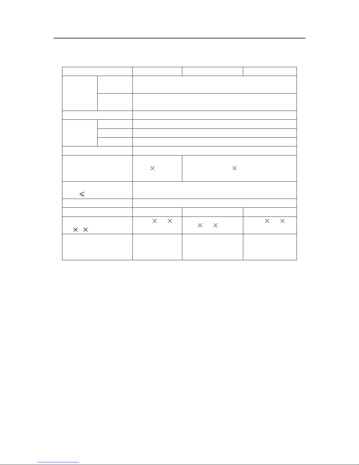
Model Number MCR51R410 MCR51R420 MCR53TF30
Color
RF system
Video system
Receiving
channel
Channels preset
Picture tube Effective
screen dimensions
(Approx.)
Audio output
(THD
Power source
Weight (Approx.)
Dimensions
H D) (Approx.)
(W
Rated power
consumption
220V AC 50Hz
Designs and specifications are subject to change without notice.
system
Sound
system
VHF
UHF
CATV
7%)
PAL4.43, NTSC3.58, NTSC4.43
D/K,I,M,B/G
PAL4.43, NTSC3.58, NTSC4.43 (50/60Hz)
C1- C12
C13-C57
Z1-Z37
236
280
210mm 406 305mm
220-240V AC, 50Hz
11.5kg 23.5kg 28kg
356
375
370mm
80W 69W 100W
600
468 486mm
2W
605
489mm
480
1
Page 3

SERVICE MANUAL
INSTRUCTIONS FOR SERVICE SAFETY AND MAINTENANCE
WARNING: BEFORE SERVICING THIS CHASSIS, READ THE X-RAY RADIATION
PRECAUTION , SAFETY PRECAUTION AND PRODUCT SAFETY NOTICE
INSTRUCTION BELOW.
X-RAY RADIATION PRECAUTION
1. The EHT must be checked every time the TV is serviced to ensure that the CRT does not emit
X-ray radiation as result of excessive EHT voltage. The maximum EHT voltage permissible in any
operating circumstances must not exceed the rated value. When checking the EHT, use the High
Voltage Check procedure in this manual using an accurate EHT voltmeter.
2. The only source of X-RAY radiation in this TV is the CRT. The TV minimizes X-RAY radiation,
which ensures safety during normal operation. To prevent X-ray radiation, the replacement
must be
3. Some components used in this TV have safety related characteristics preventing the CRT from
emitting X-ray radiation. For continued safety, replacement component should be made after
referring the PRODUCT SAFETY NOTICE below.
4. Service and adjustment of the TV may result in changes in the nominal EHT voltage of the CRT
anode. So ensure that the maximum EHT voltage does not exceed the rated value after service
and adjustment.
identical to the original fitted as specified in the parts list.
CRT
SAFETY PRECAUTION
WARNING: REFER SERVICING TO QUALIFIED SERVICE PERSONNEL ONLY.
1. The TV has a nominal working EHT voltage of 28kV. Extreme caution should be exercised when
working on the TV with the back removed.
1.1 Do not attempt to service this TV if you are not conversant with the precautions and procedures for
working on high voltage equipment.
1.2 When handling or working on the CRT, always discharge the anode to the TV chassis before
removing the anode cap in case of electric shock.
1.3 The CRT, if broken, will violently expel glass fragments. Use shatterproof goggles and take
extreme care while handling.
1.4 Do not hold the CRT by the neck as this is a very dangerous practice.
2. It is essential that to maintain the safety of the customer all power cord forms be replaced exactly
as supplied from factory.
3. Voltage exists between the hot and cold ground when the TV is in operation. Install a suitable
isolating transformer of beyond rated overall power when servicing or connecting any test
equipment for the sake of safety.
4. When replacing ICs, use specific tools or a static-proof electric iron with small power (below 35W).
2
Page 4

SERVICE MANUAL
5. Do not use a magnetized screwdriver when tightening or loosing the deflection yoke assembly to
avoid electronic gun magnetized and decrement in convergence of the CRT.
6. When remounting the TV chassis, ensure that all guard devices, such as nonmetal control buttons,
switch, insulating sleeve, shielding cover, isolati ng resistors and capacitors, are installed on the
original place.
7. Replace blown fuses within the TV with the fuse specified in the parts list.
8. When replacing wires or components to terminals or tags, wind the leads around the terminal
before soldering. When replacing safety componentsidentified by the international hazard symbols
on the circuit diagram and parts list, it must be the company-approved type and must be mounted
as the original.
9. Keep wires away from high temperature components.
PRODUCT SAFETY NOTICE
CAUTION: FOR YOUR PROTECTION, THE FOLLOWING PRODUCT SAFETY NOTICE
SHOULD BE READ CAREFULLY BEFORE OPERATING AND SERVICING THIS TV SET.
1. Many electrical and mechanical components in this chassis have special safety-related
characteristics. These characteristics are often passed unnoticed by a visual inspection and the
X-ray radiation protection afforded by them cannot necessarily be obtained by using replacements
rated at higher voltages or wattage, etc. Components which have these special safety
characteristics in this manual and its supplements are identified by the international hazard
symbols on the circuit diagram and parts list. Before replacing any of these components read the
parts list in this manual carefully. Substitute replacement components which do not have the same
safety characteristics as specified in the parts list may create X-ray radiation.
2. Do not slap or beat the cabinet or CRT, since this may result in fire or explosion.
3. Never allow the TV sharing a plug or socket with other large-power equipment. Doing so may
result in too large load, causing fire.
4. Do not allow anything to rest on or roll over the power cord. Protect the power cord from being
walked on, modified, cut or pinched, particularly at plugs.
5. Do not place any objects, especially heavy objects and lightings, on top of the TV set. Do not install
the TV near any heat sources such as radiators, heat registers, stove, or other apparatus that
produce heat.
6. Service personnel should observe the SAFETY INSTRUCTIONS in this manual during use and
servicing of this TV set. Otherwise, the resulted damage is not protected by the manufacturer.
3
Page 5
Safety Symbol Description
The lightning symbol in the triangle tells you that the voltage inside this product may be
strong enough to cause an electric shock. Extreme caution should be exercised when
working on the TV with the back removed.
This is an international hazard symbol, telling you that the components identified by the
symbol have special safety-related characteristics.
This symbol tells you that the critical components identified by the FDA marking have
FDA
special safety-related characteristics.
UL
This symbol tells you that the critical components identified by the UL marking have
special safety-related characteristics.
SERVICE MANUAL
C UL
VDE
This symbol tells you that the critical components identified by the C-UL marking have been
evaluated to the UL and C-UL standards and have special safety-related characteristics.
This symbol tells you that the critical components identified by the VDE marking have
special safety-related characteristics.
MAINTENANCE
1. Place the TV set on a stable stand or base that is of adequate size and strength to prevent it from
being accidentally tipped over, pushed off, or pulled off. Do not place the set near or over a
radiator or heat register, or where it is exposed to direct sunlight.
2. Do not install the TV set in a place exposed to rain, water, excessive dust, mechanical vibrations or
impacts.
3. Allow enough space (at least 10cm) between the TV and wall or enclosures for proper ventilation.
4. Slots and openings in the cabinet should never be blocked by clothes or other objects.
5. Please power off the TV set and disconnect it from the wall immediately if any abnormal condition
are met, such as bad smell, belching smoke, sparkling, abnormal sound, no picture/sound/raster.
Hold the plug firmly when disconnecting the power cord.
6. Unplug the TV set from the wall outlet before cleaning or polishing it. Use a dry soft cloth for
cleaning the exterior of the TV set or CRT screen. Do not use liquid cleaners or aerosol cleaners.
4
Page 6

SERVICE MANUAL
ADJUSTMENTS
Set-up Adjustments
The following adjustments should be made when a complete realignment is required or a new picture
tube is installed.
Perform the adjustments in the following order:
1. Color purity
2. Convergence
3. White balance
Notes:
The purity/convergence magnet assembly and rubber wedges need mechanical positioning.
For some picture tubes, purity/ convergence adjustments are not required.
1. Color Purity Adjustment
Preparation:
Before starting this adjustment, adjust the vertical sync, horizontal sync, vertical amplitude and
focus.
1.1 Face the TV set north or south.
1.2 Connect the power plug into the wall outlet and turn on the main power switch of the TV set.
1.3 Operate the TV for at least 15 minutes.
1.4 Degauss the TV set using a specific degaussing coil.
1.5 Set the brightness and contrast to maximum.
1.6 Counter clockwise rotate the R /B low brightness potentiometers to the end and rotate the green
low brightness potentiometer to center.
1.7 Receive green raster pattern signals.
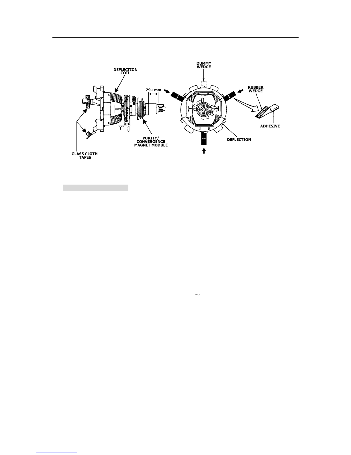
1.8 Loosen the clamp screw holding the deflection yoke assembly and slide it forward or backward to
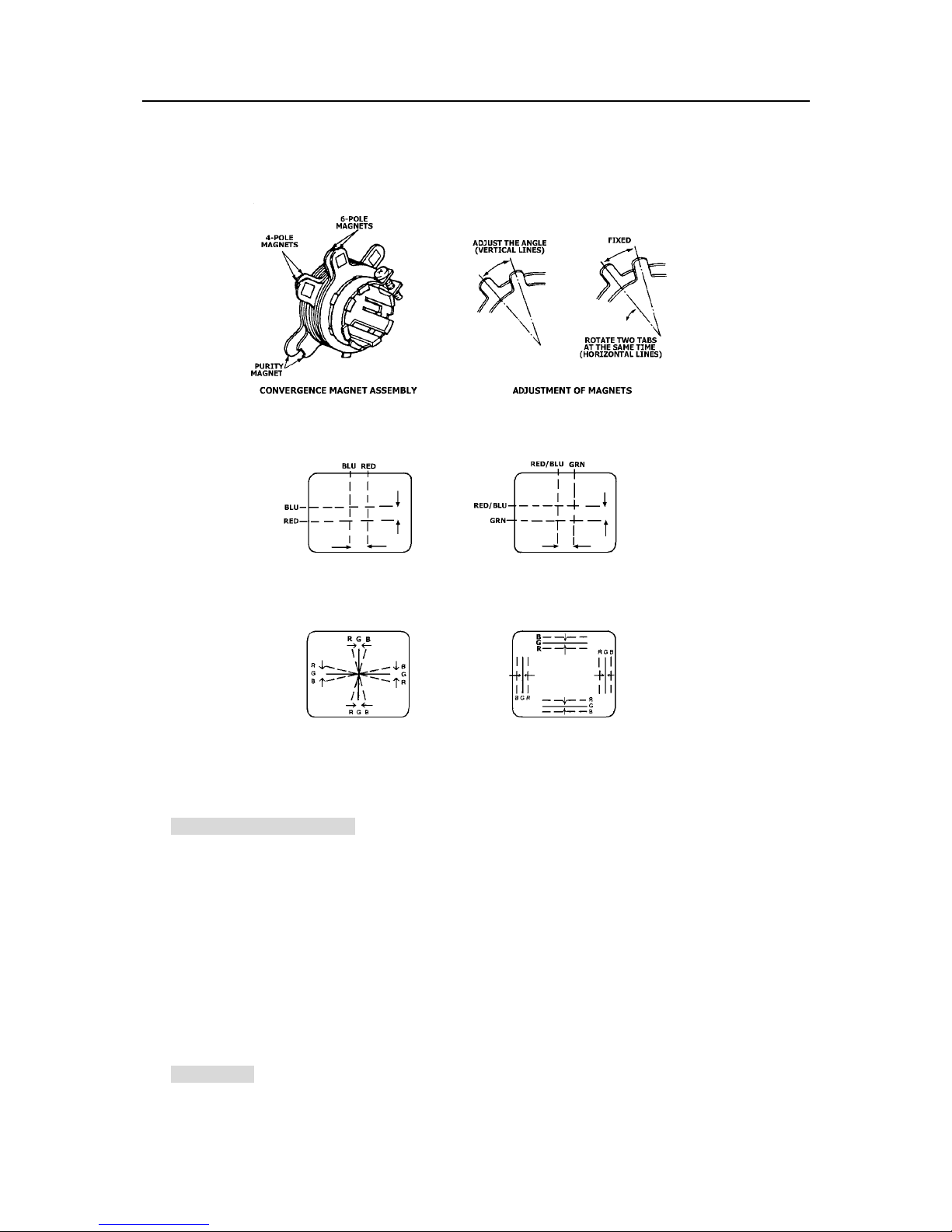
display a vertical green zone on the screen. Rotate and spread the tabs of the purity magnet
around the neck of the CRT until the green zone is located vertically at the center of the screen.
1.9 Slowly move the deflection yoke assembly forward or backward until a uniform green screen is
obtained.
1.10 Tighten the clamp screw of the assembly temporarily. Check purity of the red raster and blue
raster until purities of the three rasters meet the requirement.
5
Page 7
SERVICE MANUAL
Yok e
Fig. 1
2. Convergence Adjustment
Preparation:
Before attempting any convergence adjustment, the TV should be operated for at least 15 minutes.
2.1 Center convergence adjustment
2.1.1 Receive dot pattern.
2.1.2 Adjust the brightness/contrast controls to obtain a sharp picture.
2.1.3 Adjust two tabs of the 4-pole magnet to change the angle between them and red and blue
vertical lines are superimposed each other on the center of the screen.
2.1.4 Turn both tabs at the same time keeping the angle constant to superimpose red and blue
horizontal on the center of the screen.
2.1.5 Adjust two tabs of the 6-pole magnet to superimpose red/blue line and green line.
2.1.6 Remember red and blue movement. Repeat steps 3) 5) until optimal convergence is obtained.
2.2 Circumference convergence adjustment
2.2.1 Loosen the clamp screw holding the deflection yoke assembly and allow it tilting.
2.2.2 Temporarily put the first wedge between the picture tube and deflection yoke assembly. Move
front of the deflection yoke up or down to obtain better convergence in circumference. Push
the mounted wedge in to fix the yoke temporarily.
2.2.3 Put the second wedge into bottom.
2.2.4 Move front of the deflection yoke to the left or right to obtain better convergence in
circumference.
2.2.5 Fix the deflection yoke position and put the third wedge in either upper space. Fasten the
deflection yoke assembly on the picture tube.
2.2.6 Detach the temporarily mounted wedge and put it in either upper space. Fasten the deflection
6
Page 8
SERVICE MANUAL
yoke assembly on the picture tube.
2.2.7 After fastening the three wedges, recheck overall convergence and ensure to get optimal
convergence. Tighten the lamp screw holding the deflection yoke assembly.
Fig. 2
4-pole Magnet Movement 6-pole Magnet Movement
Center Convergence by Convergence Magnets
Incline the Yoke Up (or Down) Incline the Yoke Right (or Left)
Circumference Convergence by DEF Yoke
Fig.3
3. White Balance Adjustment
Generally, white balance adjustment is made with professional equipment. It’s not practical to get
2
good white balance only through manual adjustment. For TVs with I
C bus control, change the bus
data to adjust white balance.
Circuit Adjustments
Preparation:
Circuit adjustments should be made only after completion of set-up adjustments.
Circuit adjustments can be performed using the adjustable components inside the TV set. For TVs with
2
I
C bus control, first change the bus data.
1. Degaussing
A degaussing coil is built inside the TV set. Each time the TV is powered on, the degaussing coil
7
Page 9

SERVICE MANUAL
will automatically degauss the TV. If the TV is magnetized by external strong magnetic field,
causing color spot on the screen, use a specific degausser to demagnetize the TV in the following
ways. Otherwise, color distortion will be shown on the screen.
1.1 Power on the TV set and operate it for at least 15 minutes.
1.2 Receive red full-field pattern.
1.3 Power on the specific degausser and face it to the TV screen.
1.4 Turn on the degausser. Slowly move it around the screen and slowly take it away from the TV.
1.5 Repeat the above steps until the TV is degaussed completely.
2. Supply Voltage Adjustment
Caution: +B voltage has close relation to high voltage. To prevent X-ray radiation, set +B
voltage to the rated voltage.
2.1 Make sure that the supply voltage is within the range of the rated value.
2.2 Connect a digital voltmeter to the +B voltage output terminal of the TV set. Power on the TV and
set the brightness and sub-brightness to minimum.
2.3 Regulate voltage adjustment components on the power PCB to make the voltmeter read 130±1V.
3. High Voltage Inspection
Caution: No high voltage adjustment components inside the chassis. Please perform high
voltage inspection in the following ways.
3.1 Connect a precise static high voltmeter to the second anode (inside the high voltage cap) of the
picture tube.
3.2 Plug in the supply socket (220V, AC) and turn on the TV. Set the brightness and contrast to
minimum (0
3.3 The high voltage reading should be less than the EHT limitation.
3.4 Change the brightness from minimum to maximum, and ensure high voltage not beyond the
limitation in any case.
Nominal EHT voltage:For MCR51R410,MCR51R420,MCR53TF30 is 28
voltage: For MCR51R410,MCR51R420,MCR53TF30 is 30.5KV.
A).
1.5KV: Limited EHT
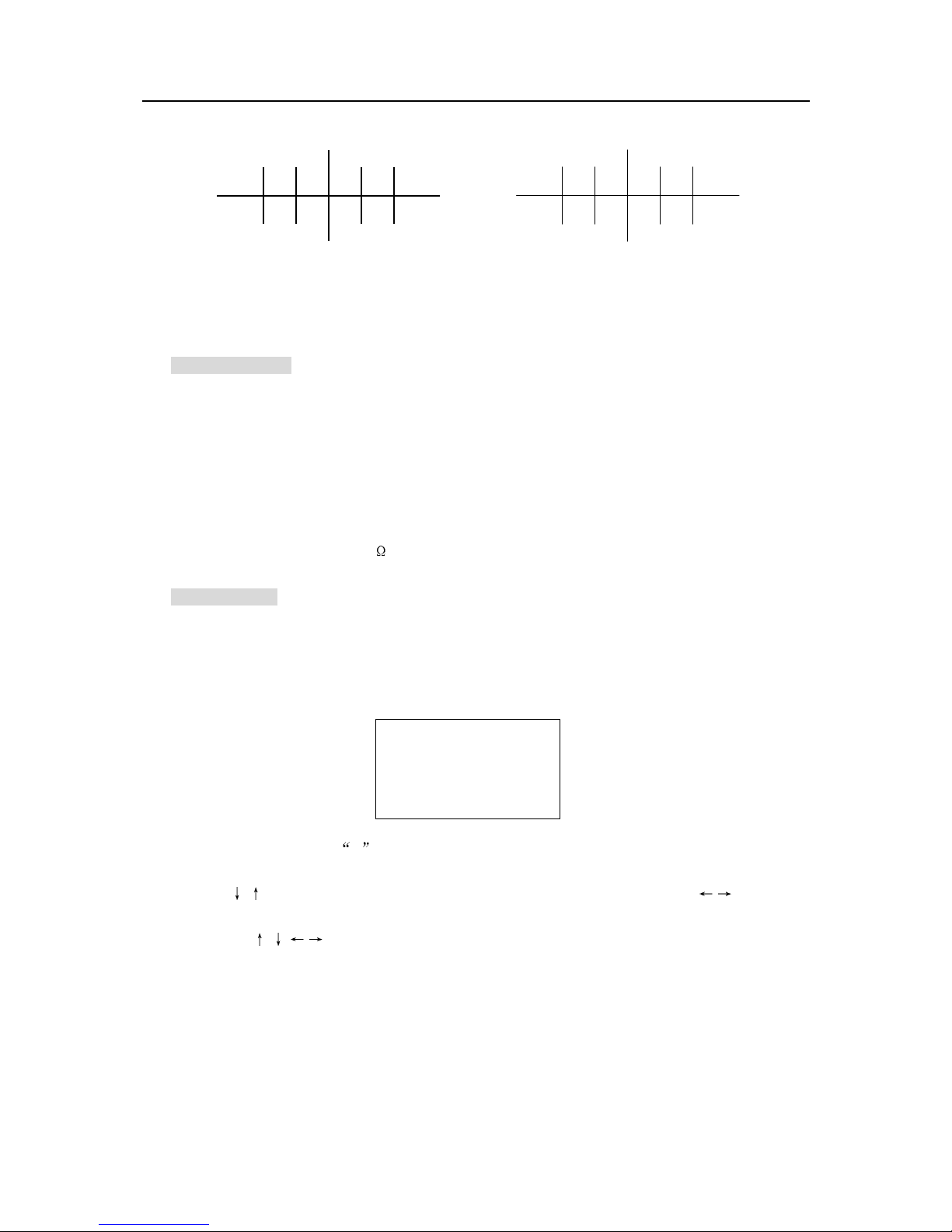
4. Focus Adjustment
Caution: Dangerously high voltages are present inside the TV. Extreme caution should be
exercised when working on the TV with the back removed.
4.1 After removing the back cover, look for the FBT on the main PCB. There should be a FCB on the
FBT.
4.2 Power on the TV and preheat it for 15 min.
4.3 Receive a normal TV signal. Rotate knob of the FCB until you get a sharp picture.
8
Page 10
SERVICE MANUAL
BeforeAdjusting AfterAdjusting
5. Safety Inspection
5.1 Inspection for insulation and voltage-resistant
Perform safety test for all naked metal of the TV. Su pply high voltage of 3000V AC, 50Hz (limit
current of 10mA) between all naked metal and cold ground. Test every point for 3 sec. and ensure
no arcing and sparking.
5.2 Requirements for insulation resistance
Measure resistance between naked metal of the TV and feed end of the power cord to be infinity
with a DC-500 high resistance meter and insulation resistance between the naked metal and
degaussing coil to be over 20M
.
6. SERVICE mode
6.1 To enter the SER VICE mode
Set the volume to 0 by the remote control. Then press and hold the MUTE button on the remote
control and MENU button on the TV at the same time for over 2 seconds. In the S mode, press the
POWER button to quit the S mode.
S
AFW:240Khz 1
( S is red and other items are yellow.)
Use the
adjust it.
The POS+/-,
function in the S mode, but 100+, 7, 8, 9 and 0 buttons not.
/ buttons on the remote control to highlight an adjustment and the / buttons to
/ / / ,1~6, RECALL, VOL+/-, MUTE and POWER buttons on the remote control
9
Page 11
SERVICE MANUAL
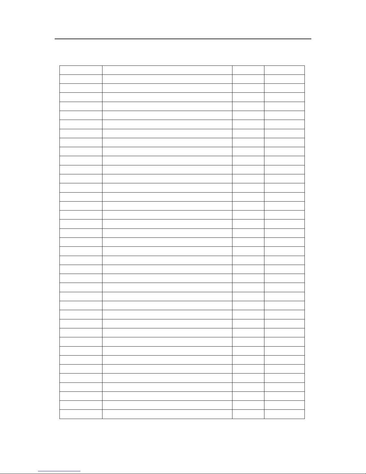
6.2 Adjustments and Bus data
Item Symbol Description Bus Data Remarks
MENU.00
V.POS /50H VERTICAL POSITION/50Hz 40
H.PHASE/50H HORIZONTAL PHASE/50Hz 11
V.SIZE/50H VERTICAL SIZE/50Hz 80
V.POS /60H VERTICAL POSITION/60Hz 40
H.PH/60H HORIZONTAL PHASE/60Hz 15
V.SIZE/60H VERTICAL SIZE/60Hz 60
V.SC VERTICAL S-CORRECTION 18
V,LINE VERTICAL LINE 19
V.SIZE CMP VERTICAL SIZE COMPENSATION 7
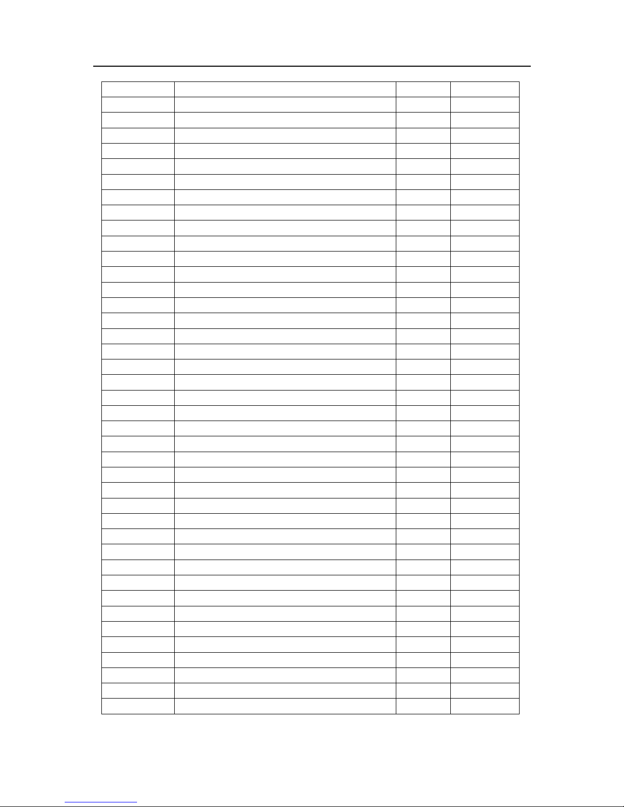
MENU.01
SUB.BIAS SUB-BRIGHT 63
SUB.CONT SUB-CONTRAST 63
V.KILL VERTICAL KILL 0
RF.AGC RF AGC 20
R.BIAS RED BIAS 130
G.BIAS GREEN BIAS 130
B.BIAS BLUE BIAS 130
R.DRIVE RED DRIVE 75
G.DRIVE GREEN DRIVE 15
B.DRIVE BLUE DRIVE 75
MENU.02
SECAM B DC SECAM B-Y 9
SECAM R DC SECAM R-Y 9
S/DVD B.DC S/DVD B-Y 6
S/DVD R.DC S/DVD R-Y 6
SYNC.KIL SYNC KILL 0
H.BLK.L HORIZONTAL BLANKING LEFT 4
H.BLK.R HORIZONT AL BLANKING RIGHT 4
CROS.B/W CROSSHATCH BLACK/WHITE 0
VIDEO.LVL VIDEO LEVEL 7
FM.LEVEL FM LEVEL 22
MENU.03
FM.MUTE FM MUTE 0
AUDIO.MUTE AUDIO MUIE 0
VIDEO.MUTE VIDEO MUTE 0
DEEM.TC DE-EMPHASIS TIME CONSTANT 0
SND.TRAP SOUND TRAP 0
10
Page 12

SERVICE MANUAL
MENU.04
SUB.COLOR SUB COLOR 63
SUB.TINT SUB TINT 32
SUB.SHARP SUB SHARP 63
AUTO FLESH AUTOMATIC FLESH 0
CORING.GAN CORING GAIN 1
C.EXT EXTERNAL CHROMA 0
C.BYPASS CHROMA BAND-PASS BYPASS 0
C.KILL ON COLOR KILL ON 0
MENU.05
FIL.SYS
COLOR.SYS COLOR SYSTEM 5
VOL.FIL VOLUME FILTER 0
VIF.SYS VIF SYSTEM 2
SIF.SYS.SW SIF SYSTEM SWITCH 0
* VIDEO.SW VIDEO SWITCH 1
MENU.06
R/B G.BAL R-Y/B-Y GAIN BALANCE 15
R/B ANGLE R-Y/B-Y ANGLE 15
CD. MODE VERTICAL COUNTDOWN MODE 0
GREY MODE GREY MODE
V.SETUP VERTICAL SETUP 0
MENU.07
BLANK.DEF BLANK.DEFEAT 0
BRT.ABL.TH BRIGHT ABL THRESHOLD 1
RGB TEMP RGB TEMPERATURE CHARACTERISTICS 1
BRT.ABL.DF BRIGHT ABL DEFEAT 1
MID.STP.DF BRIGHT MID STOP DEFEAT 1
FBP.BLK.SW FBP.BLANKING OR.SWITCH 0
MENU.08
DIGIT AL.OSD DIGITAL OSD MODE 0
OSD.CONT OSD CONTRAST CONTROL? 40
OSD.CONTST OSD CONTRAST CONTROL? 0
OSD. H.POS OSD HORIZONTAL POSITION 22
MENU.09
H.FREQ HORIZONTAL FREQUENCY 46
FM.GAIN FM GAIN 0
C.KILL.OFF COLOR KILL OFF 0
AUDEO.SW AUDEO SWITCH 0
T.DISBLE TEST MODE SWITCH DISABLE 1
MENU.10
FILTER SYSTEM
SELECT Y/C FIL TER MODE
1
11
Page 13
SERVICE MANUAL
G/Y ANGLE G-Y ANGLE 0
COL KIL OP COLOR KILLER OPERATIONAL POINT 5
CBCR-IN YCbCr INPUT or SECAM INPUT 1
Y-APF YCbCr ALL PASS FILTER SELECT 0
PRE SHOOT PRE-SHOOT SELECT 0
WPL OPE WHITE PEAK LIMITER OPERATING POINT 0
DC REST DC RESTORATION SELECT 0
BK STR STA BLACK STRETCH START 3
BK STR GAN BLACK STRETCH GAIN 2
MENU.11
OVER MD SW OVER MD SW? 0
Y GAMMA Y GAMMA 0
FSC C.SYNC FSC C.SYNC? 1
VBLK SW V BLANKING CONTROL SW 0
SND TRAP SOUND TRAP CONTROL 1
HALF TONE HALF TONE LEVEL 3
HALF T SW HALF TONE ON/OFF SW 1
TST VRESET TST VRESET? 0
MENU.12
E/W DC E/W DC 32
E/W AMP E/W AMP 32
E/W TILP E/W TILP 32
E/W C TOP E/W C TOP 5
E/W C BOTM E/W C BOTM 5
MENU.13 MENU.13
E/W TEST E/W TEST 7
HSIZE COMP HORIZONTAL SIZE COMPENSATION 7
IF TEST 3B IF TEST 3B 0
V.LEV ADJ VIDEO.LEVEL ADJUSTMENT 0
OV MOD LEV OV MOD LEV 5
PRE/OVER PRE/OVER SHOOT 0
C.VCO SW CHROMA.VCO SWITCH 0
C.VCO ADJ CHROMA VCO ADJUSTMENT 3
MENU.14 MENU.14
VNSYNC VNSYNC 0
TINT.THROU TINT.THROU 0
HLOCK.VDET HLOCK.VDET 1
MENU.15 MENU.15
OPT.1CHIP OPT.1CHIP 0
12
Page 14

SERVICE MANUAL
OPT.VIDEO OPT.VIDEO 1
OPT.AV1AV2 OPT.AV1AV2 1 0 for
MCR51R410
OPT.AV3 OPT.AV3 0
OPT.S-VHS OPT.S-VHS 0
OPT.YUV OPT.YUV 0
OPT.COMB OPT.COMB 0
OPT.BYPASS OPT.BYPASS 0
MENU.16 MENU.16
OPT.VM OPT.VM 0
OPT.BLUEBK OPT.BLUEBK 1
OPT.V-CHIP OPT.V-CHIP 1
OPT.CCD OPT.CCD 1
OPT.CLOCK OPT.CLOCK 1
OPT.P-ON OPT.P-ON 0
X-RAY VOLT X-RAY VOLTAGE 40
SRCH.SPEED SEARCH.SPEED 0
ROM
CORREC
MENU.17 MENU.17
OPT.BTSC OPT.BTSC 0
OPT.AV-INP OPT.AV-INPUT 0
OPT.BBE OPT.BBE 0
SUB.BASS SUB.BASS 3
SUB.TREBLE SUB.TREBLE 3
OPT.COLOR OPT.COLOR 0
OPT.LNG1 OPT.LNG1 0
OPT.LNG2 OPT.LNG2 0
OPT.LNG3 OPT.LNG3 0
MENU.18 MENU.18
LOUDNESS LOUDNESS 9
FM/AM.PRES FM/AM.PRESET 63
SCART.PRES SCART.PRESET 27
SCART.VOL SCART.VOL 117
OPT.AVC OPT.AVC 1
AVC.DECAY AVC.DECAY 2
ROM CORRECTION 0
Notes:
The data sheet may differ dependent on different models.
The data sheet may differ dependent on different CRTs for the same model.
The items marked with “*” are adjustments used for manufacturing.
13
Page 15

STRUCTURE AND CHASSIS FUNCTION DESCRIPTION
1 Structure Block Diagram
14
Page 16

2 Block Diagram for Supply Voltage System
15
Page 17

3 System Control Block Diagram
16
Page 18

SERVICE MANUAL
4 Chassis Description
MCR51R410/420/MCR53TF30 These TV uses CN-12C5 chassis which mainly includes a small signal
processor LA76818A
LA7840 and sound power amplifier TDA7057AQ. The switch power circuit is formed of hybrid IC
STR-G5653. TV/VIDEO and A V input/output arecontrolled by HEF4053BP and KA2192BV. LA76818A,
a small signal processing chip developed by Japan-based Sanyo, is designed for use in
PAL/NTSC/SECAM televisions, featuring high-integrity, performance & reliability and advanced
functions.
Microcontroller LC863440, also developed by Japan-based Sanyo, is an I
single-chip microprocessor . It consists of 48K
(36 characters
interface, featuring high performance and wide usage.
The chassis has features of multi system reception and audio/video input/output.
With DVD component input, LA76818A improves its performance greatly based on LA76810.
The CN-12C5 chassis series mainly use the following ICs and assemblies.
Serial
No.
Position Type Function Description
1 N101 LA76818A Small signal processor
2 D701
3 D702 AT24C04/ST24C04 EEPROM
4 N301 LA7840/L Vertical scan output stage circuit
5 N191 TDA7057AQ Sound power amplifier
6 NV01 KA2102B/KA2192B TV/Video switch circuit
7 NK01 HEF4053BP Analog switch circuit
8 N510 STR-G5653 Power supply circuit
9 U101 TDQ-3B8/136 Tuner
microcontroller LC863440/CH04T1232 vertical scan output stage circuit
2
C bus control 8-bit CMOS
8 ROM bit 640 8 RAM bit OSD controller on chip
16lines), remote control signal sensor, PWM output (7bit 3ch), I2C bus serial
Table Key ICs and Assemblies
LC86F3448A/
CH04T1232
Microcontroller
17
Page 19

SERVICE DATA
1 Technical Data of Key ICs
1.1 Small signal processor LA76818A
a. Block Diagram
SERVICE MANUAL
Fig.7
18
Page 20

SERVICE MANUAL
Pin Function Pin Function
1 Audio Output 54 SIF Input
2 FM Output/Selected Audio Output 53 SIF APC Filter
3 PIF AGC 52 SIF Output
4 RF AGC Output 51 Ext. Audio Input
5 PIF Input1 50 APC Filter
6 PIF Input2 49 VCO Coil 1
7 IF Ground 48 VCO Coil 2
8 IF Vcc 47 VCO Filter
9 FM Filter 46 Video Output
10 AFT Output 45 Black Level Detector
11 Bus Data 44 Internal Video Input (S-C IN)
12 Bus Clock 43 Video/Vertical Vcc
13 ABL 42 External Video Input (Y In)
14 Red Input 41 Video/Vertical Bus Ground
15 Green Input 40 Selected Video Output
16 Blue Input 39 Chroma APC1 Filter
17 Fast Blanking Input 38 4.43MHz Crystal
18 RGB Vcc 37 Clamp Filter
19 Red Output 36 Chroma APC2 Filter
20 Green Output 35 SECAM R-Y Input (Cr input)
21 Blue Output 34 SECAM B-Y input (Cr input)
22 Fsc output/C-Sync output 33 CCD/Horizontal Ground
23 Vertical Output 32 CCD Filter
24 Ramp ALC Filter 31 CCD Vcc
25 Horizontal/Bus Vcc 30 Clock (4MHz) Output
26 Horizontal/AFC Filter 29 VCO IREF
27 Horizontal Output 28 Flyback Pulse Input
b. LA76818A Pin Assignment
19
Page 21

SERVICE MANUAL
1.2 Microcontroller LC86F3448A/CH04T1232(36 DIP)
1.2.1 Overview
The LC86F3448A are 8-bit single chip microcontrollers with the following on-chip functional blocks:
- CPUOperable at a minimum bus cycle time of 0.424ȝs
- On-chip ROM capacity
Program ROM:32K/28K/24K/20K/16K bytes
CGROM:16K bytes
- On-chip ROM capacity: 512 bytes
- OSD RAM: 352×9 bits
- Closed-Caption TV controller and the on-screen display controller
- Closed-Caption data slicer
- Four channels×6-bit AD Converter
- Three channels×7-bit PWM
- 16-bit timer/counter, 14-bit base timer
- IIC-bus compliant serial interface circuit (Multi-master type)
- ROM correction function
- 1 1-source 8-vectored interrupt system
- Integrated system clock generator and display clock generator
Only one X
TV control and the Closed Caption function
All of the above functions are fabricated on a single chip.
tal oscillator (32.768kHz) for PLL reference is used for both generators
20
Page 22

1.2.2 System Block Diagram
SERVICE MANUAL
1.2.3 Refer to Table 3 about Functions and Service Data of LC86F3448A s Pins.
Fig.8
21
Page 23

SERVICE MANUAL
1.3 EEPROM AT24C04/ST24C04
1.3.1 Features
·Data EEPROM internally organized as 512 bytes and
32 pages×16 bytes
·Page protection mode, flexible page-by-page
hardware write protection
-Additional protection EEPROM of 32 bits, 1 bit per
data page
-Protection setting for each data page by writing its
protection bit
-Protection management without switching WP pin
·Low power CMOS
·Vcc=2.7 to 5.5V operation
2
·Two wire serial interface bus, I
C-Bus compatible
·Filtered inputs for noise suppression with Schmitt trigger
·Clock frequency up to 400 kHz
·High programming flexibility
-Internal programming voltage
-Self timed programming cycle including erase
-Byte-write and page-write programming, between 1 and 16 bytes
-Typical programming time 6 ms(<10ms) for up to 16 bytes
·High reliability
-Endurance 10
6
-Data retention 40 years
cycles
1)
1)
-ESD protection 4000 V on all pins
·8 pin DIP/DSO packages
·Available for extended temperature ranges
-Industrial: -40
to +85
-Automotive” -40 to +125
Fig.9
22
Page 24

1.3.2 Pin Configuration
SERVICE MANUAL
1.3. 3 Block Diagram
Fig.10
1.3.4 Refer to Table 4 about Functions and Service Data of ST24C04
Fig.1 1
s Pins.
23
Page 25

SERVICE MANUAL
1.4 Vertical scan output stage circuit LA7840/L
1.4.1 Features
Low power dissipation due to built-in pump-up circuit
Vertical output circuit
Thermal protection circuit built in
Excellent crossover characteristics
DC coupling possible
1.4.2 Block Diagram
1.4.3 Refer to Table 6 about Functions and Service Data of LA7840 s Pins.
Fig.12
24
Page 26

1.5 Sound power amplifierTDA7057AQ
SERVICE MANUAL
1.5.1 Features
DC volume control
Few external components
Mute mode
Thermal protection
Short-circuit proof
No switch-on and switch-off clicks
Good overall stability
Low power consumption
Low HF radiation
ESD protected on all pins.
1.5.2 General Description
The TDA7057AQ is a stereo BTL output
1.5.3 Block Diagram
.
amplifier with DC volume control. The device is
designed for use in TVs and monitiors, but is
also suitable for battery-fed portable
recorders and radios.
Missing Current Limiter (MCL)
A MCL protection circuit is built-in. The MCL
circuit is activated when the difference in
current between the output terminal of each
amplifier exceeds 100 mA (typical 300 mA).
This level of 100 mA allows for single-ended
headphone applications
.
1.5.4 Refer to Table 7 about Functions and Service Data of TDA7057AQ’s Pins.
Fig.13
25
Page 27

SERVICE MANUAL
1.6 TV/Video switch circuit KA2102B/KA2192B
1.6.1 Features
The KA2102B (NY01) TV/Video switch circuit is an electronic switch circuit controlling four sets of
audio signal inputs, three sets of video signal inputs, two sets of Y/C separation signals inputs, one set
of video signal output, one set of Y/C separation signal output and one set of audio signal output.
1.6.2 Block Diagram
Fig.14
1.6.3 Value Table
Level for Control Terminal
Switchover Mode
(15) (16)
HHTV
HLAV1
LHSVHS
LLAV2
1.6.4 Refer to Table 5 about Functions and Service Data of KA2102B/KA2192B s Pins.
26
Page 28

SERVICE MANUAL
1.7 Analog switch circuit HEF4053BP
1.7.1
Description
The HEF4053 is a triple 2-channel analog multiplexer/demultiplexer with a common enable input (
Each multiplexer/demultiplexer has two independent inputs/outputs (Y
and Y1), a common
0
input/output (Z), and select inputs (Sn). Each also contains two-bidirectional analog switches, each
with one side connected to an independent input/output (Y
common input/output(Z). selected (low impedance ON-state) by Sn. With
and Y1) and the other side connected to a
0
HIGH, all switches are in
E
the high impedance OFF-state, independent of SA to SC.
VDD and VSS are the supply voltage connections for the digital control inputs (S
The V
positive limit and V
For operation as a digital multiplexer/demultiplexer, V
to VSS range is 3 to 15V.The analog inputs/outputs (Y0, Y1 and Z) can swing between VDD as a
DD
as a negative limit. VDD-VEE may not exceed 15 V.
EE
is connected to VSS (typically ground).
EE
to SC and E).
A
1.7.2 Block Diagrams
).
E
Fig.15
27
Page 29

1.7.3 Function Table
SERVICE , MANUAL
Inputs
E
Sn
LL Y0n-Z
LH Y1n-Z
H X none
1.7.4 Refer to Table 8 about Functions and Data of HEF4053’s Pins.
Channel On
n
n
Notes
H=HIGH state (the more positive voltage)
L=LOW state (the less positive voltage)
X=STATE is immaterial
1.8 Power supply circuit STR-G5653
The Series STR-G5653/F6654 is specifically designed to satisfy the requirements for increased
integration and reliability in off-line quasi-resonant flyback converters. The series incorporates a
high-precise error amplifying control and drive circuit with discrete avalanche-rated power MOSFET,
featuring fewer external components, small-size and standard power supply.
Covering the power range from below 25 watts up to 300 watts for 100/115/230 VAC inputs, and up to
150 watts for 85 to 265 VAC universal input, these devicescan be used in a range of applications, from
battery chargers and set top boxes, to televisions, monitors, and industrial power supply units.
Cycle-by-cycle current limiting, under-voltage lockout with hysteresis, over-voltage protection, and
thermal shutdown protects the power supply during the normal overload and fault conditions.
Low-current startup and a low-power standby mode selected from the secondary circuit completes a
comprehensive suite of features. The series is provided in a five-pin overmolded SIP style package,
affording dielectric isolation without compromising thermal characteristics.
(1) Features
Flyback Operation with Quasi-Resonant Soft Switching
for Low Power Dissipation and EMI
Rugged Avalanche-Rated MOSFET
Soft drive circuit MOSFET
Adjustable MOSFET switching speed
Choice of MOSFET Voltage and rDS(on)
Full Over-Current Protection (no blanking)
Under-Voltage Lockout with Hysteresis
Over-Voltage Protection
Direct Voltage Feedback
Low Start-up Current (100ȝAmax)
Low-Frequency, Low-Power Standby Operation
28
Page 30

Overmolded 5-Pin Package
(2) Circuit Block Diagram
(3) Pin Configuration and Functions
SERVICE , MANUAL
Fig.16
a. Pin function for STR-G5653
Pin No.
Symbol Function Description
1 D MOSFET drain
2 S MOSFET source
3 GND Ground
4VINSupply voltage input for control circuit
5 OCP/FB Over-current protection detection signal/ voltage-limiting signal input
Dwg MK-003-50
Fig.17
29
Page 31

SERVICE , MANUAL
b. Pin function for STR-F6654
Pin No. Symbol Function Description
1 OCP/FB Over-current protection detection signal/ voltage-limiting signal input
2 S MOSFET source
3 D MOSFET drain
4VINSupply voltage input for control circuit
5 GND Ground
(4)Difference between STR-G5653 and STR-F6654
a.Different size: STR- F6654 is larger
b.Different pin functions
c.Different electric characteristics: Larger power output, switching current, avalanche-rated and internal
allowable power consumption for STR-F6654
2. Service Data of Key ICs
Table 2 Service Data of LA76818A (N101)’s Pins
Pin No. Function Description
GDM8145 Multimeter
1 Audio Output
Voltage(V)
2.2 6.82 7.6
Positive Resistance(k ) Negative Resistance(k )
2 FM output/Selected Audio Output 2.41 6.59 486.6
3 PIF AGC 1.98 6.99 512.7
4 RF AGC Output 3.73 26.4
5 PIF Input1 2.84 6.71 29
6 PIF Input2 2.84 6.71
7IFGround 0 0 0
8 IF Vcc 5 0.41 0.38
9 FM Filter 2.22 7.06 0.76
10 AFT Output 4.75 5.28
11 Bus Data 4.8 14.48 380
12 Bus Clock 4.8 5.316 360
13 ABL 3.24 7.036 172
14 Red Input 0 7.04 17.5
15 Green Input 0.022 7.02 60.5
16 Blue Input 0.022 7.03 6.02
17 Fast Blanking Input 0.015 3.24 3.2
18 RGB Vcc 8.234 0.46 0.45
19 Red Output 2.8 5.33 6.05
20 Green Output 2.96 5.34 6.07
21 Blue Output 2.8 5.33 6.05
30
Page 32

SERVICE , MANUAL
22 Fsc Output/Sync Output 0 10 6.04
23 Vertical Output 2.31 2.31 2.3
24 Ramp ALC Filter 2.786 583.4 6.45
25 Horizontal/Bus Vcc 5.188 6.8 4.34
26 Horizontal/AFC Filter 2.686 582.2 6.54
27 Horizontal Output 0.702 1.41 1.4
28 Flyback Pulse Input 1.056 22.84 6.16
29 VCO IREF 1.71 4.72 4.52
30 Clock (4MHz)Output 0.915 4.9 5.015
31 CCD Vcc 0 0.49 0.5
32 CCD Filter 0 4.92
33 CCD/ Horizontal Ground 0 0 0
34 SECAM B-Y Input (Cb Input) 2.375 544 6.275
35 SECAM R-Y Input (Cr Input) 2.377 544 6.273
36 Chroma APC2 Filter 3.237 582 6.644
37 Clamp Filter 1.738 6.67
38 4.43MHz Crystal 2.76 350 6.4
39 Chroma APC1 Filter 3.42
40 Selected Video Output 2.22
41 Video/Vertical Bus Ground 0
42 External Video Output(Y In) 2.63
43 Video/Vertical Vcc 5
44 Internal Video Input(S-C IN) 2.5 572 6.358
45 Black Level Detector 2.27 0 6.304
46 Video Output 3.57 10 5.865
47 VCO Filter 2.58
48 VCO Coil 2 4.2 1.054
49 VCO Coil 1 0 1.04
50 APC Filter 2.27 41.7 6.13
51 Ext. Audio Input 2.18
52 SIF Output 2.20 356 104
53 SIF APC Filter 2.4 555 485.4
54 SIF Input 3.16
6.56
6.254
0
0.42
247
22.4
31
Page 33

SERVICE , MANUAL
Table 3 Functions and Service Data of LC86F3448A (D701)’s Pins
GDM8145 Multimeter
Ground Resistance (k)
Pin No.
Function Description
Voltage of
Pin (V)
Measure with red
probe while
grounding black
probe.
Measure with
black probe while
grounding red
probe.
1 Not connected 1.50 11.8 4.40
2 Not connected 1.43 12.1 5.20
3 Bus data line 4.70 11.6 6.20
4 Bus clock line 4.47 12.1 6.00
5 Ground 0.00 0.00 0.00
6 Input terminal for clock oscillating signal 1.78 12.6 5.1
7
Output terminal for clock oscillating signal
2.88 12.0 4.91
8 Supply voltage 5.31 7.90 3.72
9 Button-control voltage input terminal 1 0.02 9.70 5.34
10 AFT voltage input terminal 2.47 4.90 5.08
11 X-RAY detection input 2.25 6.70 4.59
12 Button-control voltage input terminal 2 0.015 8.86 3.81
13 Reset 5.27 4.67 1.88
14 Character oscillating filter 3.87 1.11 4.98
15 Video signal input terminal 3.53 12.3 4.50
16 Three bits input/output terminals 0.01 9.76 15.0
17 Input terminal for vertical flyback pulse 5.07 15.4 18.1
18
Input terminal for horizontal flyback
pulse
4.62 17.4 18.4
19 R character output terminal 0.015 3.92 3.29
20 G character output terminal 0.014 3.95 3.71
21 B character output terminal 0.015 3.19 3.66
22 Output terminal for fast blanking signal 0.015 6.50 3.67
23 Mute 0.015 18.7 17.62
24 Standby control 0.015 1.43 7.30
25 Not connected 1.23 9.50 6.65
26 Control terminal for production modes 4.61 13.0 6.95
27 Degaussing circuit control 0.014 3.713 3.42
28 Remote control signal input 5.19 12.2 5.32
29 Not connected 5.30 12.4 5.49
30 Not connected 5.30 12.6 5.42
31 Not connected 0.01 12.7 5.35
32 Not connected 0.01 12.7 5.30
33 Output terminal for on/off control signals 5.30 12.7 6.59
32
Page 34

SERVICE , MANUAL
34 Output terminal for AV2 on/off control 5.30 11.8 6.36
35 Output terminal for AV1 on/off control 5.30 11.4 6.33
36 Output terminal for AV0 on/off control 5.29 141.2 6.33
Table 4 Functions and Service Data of AT24C04/ST24C04 (D702)’s Pins
DT890D Digital Multimeter
Pin No.
Function Description
Voltage of
Pin (V)
Ground Resistance ( )
Measure with red
probe while
grounding black
probe.
egative Resistance(k)
Measure with black
probe while
grounding red
probe.
1 Address input terminal 0.00 0.00 0.00
2 Address input terminal 0.00 0.00 0.00
3 Address input terminal 0.00 0.00 0.00
4 Common ground 0.00 0.00 0.00
5 Clock line 4.94 6.85 4.83
6 Data line 4.94 6.89 5.15
7 PW write protection terminal 0.00 9.58 5.31
8 Supply voltage 5.32 3.5 3.25
Table 5 Functions and Service Data of KA2102B/K2192B (NV01)’s Pins
DT890D Digital Multimeter
Ground Resistance (K )
Pin No.
Function Description
Voltage of
Pin (V)
Measure with red
probe while
grounding black
probe.
Measure with
black probe while
grounding red
probe.
1 L TV IN 5.67 6.45 3.53
2 R TV IN 5.67 6.45 3.74
3 TV IN 5.67 6.57 4.02
4 LS IN 5.69 6.45 3.66
5 RS IN 5.69 6.47 3.72
6 SY IN 5.54 6.85 3.96
7
TV SW
0.00 0.00 0.00
8 SC IN 5.54 6.75 3.85
9 L1 IN 5.69 6.43 3.36
10 R1 IN 5.70 6.37 3.72
11 E1 IN 5.56 6.85 3.96
12 L2 IN 5.70 6.43 3.87
33
Page 35

SERVICE , MANUAL
13 R2 IN 5.70 6.33 3.67
14 E2 IN 5.56 6.83 4.01
15 SW1 5.25 6.84 5.59
16 SW2 5.25 6.85 5.59
17 MUTE 0.00 0.00 0.00
18 Y OUT 3.89 1.418 1.51
19 GND 0.00 0.00 0.00
20 C OUT 3.84 0.96 1.15
21 R OUT 4.37 6.63 3.35
22 L OUT 4.37 6.61 3.31
23 NC 0.06 6.71 3.97
24 Y IN 5.55 6.70 4.18
25 SYNC CLAMP 3.47 6.80 5.75
26 C IN 5.57 6.67 4.07
27 NC 0.25 6.69 4.13
28 VCC 9.38 0.34 0.33
29 VCC 9.38 0.31 0.30
30 V OUT 3.17 6.47 0.48
Table 6 Functions and Service Data of LA7840 (N301)’s Pins
DT890D Digital Multimeter
Ground Resistance (K )
Pin No. Function Description
Voltage of
Pin (V)
Measure with red
probe while grounding
black probe.
Measure with black
probe while
grounding red
probe.
1 Ground 0 0 0
2 Vertical output terminal 14.8 365 360
3 Pump supply voltage input 24.5 584
4 Reference voltage 2.24 660 600
5 Inverting input terminal 2.23 800 672
6 Supply voltage 24 770 465
7 Vertical flyback pulse output terminal 2.25 1167 638
34
Page 36

SERVICE , MANUAL
Table 7 Functions and Service Data of TDA7057AQ (N191)’s Pins
Pin No. Function Description
GDM8145 Multimeter
Voltage (V)
Positive Resistance (K ) Negative Resistance (K )
1 Volume control input 0.95 6.85 6.15
2 Not connected 0.00
3 Audio R signal input 2.38 12.59 6.51
4 Supply voltage 17.48 0.47 0.47
5 Audio L signal input 2.37 12.5 6.51
6 Ground 0.00 0.00 0.00
7 Volume control input 0.95 6.85 0.15
8 Left channel in-phase signal output 8016 6.46 5.59
9 Ground 0.00 0.00 0.00
10 Left channel inverting signal output 8.25 6.46 5.59
11 Right channel inverting signal output 8.24 6.46 5.59
12 Ground 0.00 0.00 0.00
13 Right channel in-phase signal output 8.13 6.46 5.59
Table 8 Functions and Service Data of HEF4053BP (NK01)’s Pins
DT890D Digital Multimeter
Ground Resistance (Kȍ)
Pin No.
Function Description
Voltage of
Pin (V)
Measure with red
probe while
grounding black
probe.
Measure with black
probe while
grounding red
probe.
1 Signal input terminal 3.91 6.31 012
2 Signal input terminal 5.01 6.31 0.11
3 Signal input terminal 0.00 0.00 3.41
4 Signal output terminal 0.02 6.07 0.05
5 Signal input terminal 0.22 6.17 3.72
6 Ground 0.00 0.00 0.00
7 Ground 0.00 0.017 0.00
8 Ground 0.00 0.017 0.00
9 Control signal input terminal 4.42 6.27 6.08
10 Control signal input terminal 4.42 6.24 6.07
11 Control signal input terminal 4.42 6.24 6.08
12 Signal input terminal 3.30 6.08 3.66
13 Signal output terminal 1.31 5.96 4.72
14 Signal input terminal 1.44 5.95 3.69
15 Signal output terminal 1.43 6.017 4.01
16 Supply voltage 5.04 0.352 0.33
35
Page 37

SERVICE , MANUAL
3. Replacement of Parts
3.1 Description
Many electrical and mechanical components in this chassis have special safety-related
characteristics. Components which have these special safety characteristics in this manual
and its supplements are identified by the international hazard symbols or UL,C-UL, FCC, FDA
or VDE marking on the circuit diagram and parts list. When replacing any of these components,
substitute the one which has the same safety characteristics as specified in the manual.
Description of the special markings:
A: The components identified by the A marking have special safety-related characteristics.
AE: The components identified by the AE marking are listed by EMC and have special
safety-related characteristics.
CB: The components identified by the CB marking have been evaluated to the CB standard.
E: The components identified by the E marking are listed by EMC
G: The components identified by the G marking have critical characteristics.
Z: The components identified by the Z marking have important characteristics.
APPENDIX
1. Parts List
2. Circuit Board Component Views
3. Schematic Diagrams
4. Printed Circuit Board Diagrams
36
Page 38

Page 39

Printed Circuit Board diagrams (1)
Page 40

Page 41

Page 42

MCR51R410 (Main Diagram)
Chassis : CN-12C5
Page 43

Tema: tv rca mod. mcr 51r310 busco manual. (Leído 87 veces)
ricarant
Member
Karma: +2/-0
Desconectado
Sexo:
Profesión o Título: TECNICO EN ELECTRONICA
País: EL SALVADOR CENTRO AMERICA
Mensajes: 26
Re: tv rca mod. mcr 51r310 busco manual.
« Respuesta #5 en: Hoy a las 12:57:07 »
________________________________________
Claro mi migo aqui te mando la secuencia para el modo service : vol a cero, presiona
mute en control remoto y menu en tv al mismo tiempo y ya estas en modo service ojala
y te sirva CON LOS CURSORES UP,DONW CAMBIA PARAMETROS
CURSORES LATERALES CAMBIA VALORES
bueno espero y soluciones tu problema.
saludos desde El salvador
 Loading...