

Page 1
--- \
Contents
I
I
I
Aluminum Foil
5,15,17-19
Door Removal 25
I
I Anti-Tip Device
2,3,28,37
Light; Bulb Replacement 12,24
I
Appliance Registration
2 Oven Bottom
23
I
Care and Cleaning
21-26
Oven Vents 13,26
I
Clock/Timer
8 Roasting/Roasting Guide 17,18
IC
onsumer Services
47
Shelves 13,17
1
I
Important Phone Numbers 47
Power Outage
12
Ic
onverting to LP
Problem Solver 43,44
I
I
or Natural Gas 38-42
Thermostat Adiustment-
1
J
I Features 6,7 Do It Yourself 16
I
.
I
Installation Instructions 27-37
Safety Instructions 3-5
I Air Adjustment 36 Surface Cooking 9-11
I
I
Flooring
29 Burners 9-11
I Levelim
37
Control Settings 10
I
Model and Serial Numbers 2
Cooktop Comparison 9
10
ven 12-20
Cookware ~lDs
11
I
Baking 14,15
Flame Size
11
I
Broiling/Broiling Guide 19,20
Lighting Instructions
9,10
I
Control Settings
12
Warranty
Back Cover
#
I’UCA
Models
LGB116
LGB126
LGB146
LGB156
Use and Care & Installation
L of Your Gas Range
7?xk2NG
Page 2
HELP US HELP YOU...
Read this guide carefully.
It is intended to help you operate and maintain your
new range properly.
Keep it handy for answers to your questions.
If you don’t understand something or need more help,
write (include your phone number):
Consumer Affairs
Appliance Park
Louisville, KY 40225
Write down the model and serial numbers.
Depending on your range, you’ll find the model and
serial numbers on a label on the tint of the range,
behind the kick panel, storage drawer or broiler drawer.
These numbers are also on the Consumer Product
Ownership Registration Card that came with your
range. Before sending in this card, please write these
numbers here:
Model Number
Seriil Number
Use these numbers in any comespondence or service
calls concerning your range.
If you received a damaged range...
Immediately contact the dealer (or builder) that sold
you the range.
Save time and money. Before you
request service...
Check the Problem Solver in the back of this guide.
It lists causes of minor operating problems that you
can correct yourself.
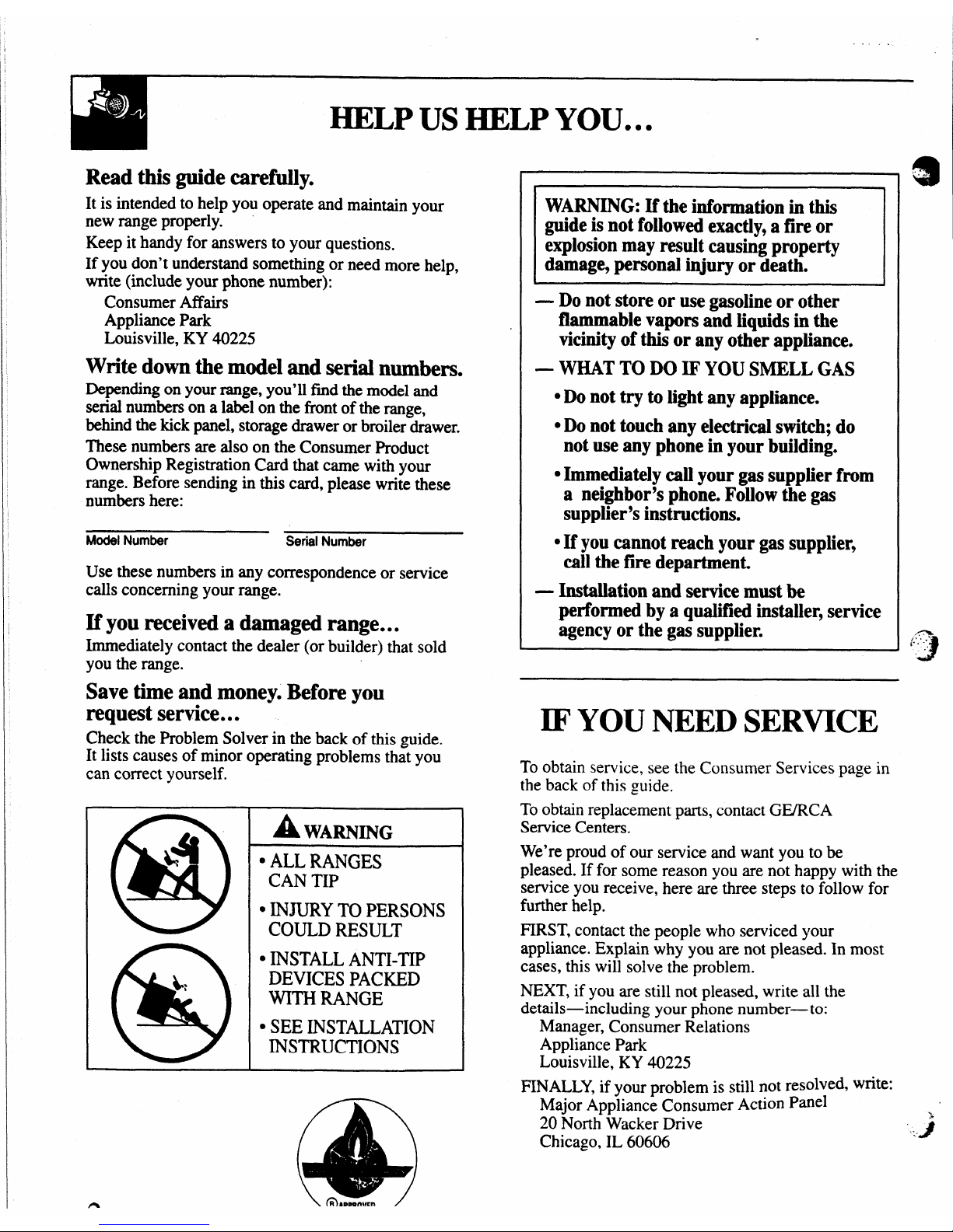
A WARNING
‘ ALL RANGES
CAN TIP
● ~JURY TO PERSONS
COULD RESULT
● ~sTALL ANTI.~p
DEVICES PACKED
WITH RANGE
● SEE INSTALLATION
INSTRUCTIONS
@
WARNING: If the information in this
guide is not followed exactly, a fire or
explosion may result causing property
damage, personal injury or death.
●
— Do not store or use gasoline or other
flammable vapors and liquids in the
vicinity of this or any other appliance.
—
WHAT TO DO IF YOU SMELL GAS
. Do
not try to light any appliance.
● Do not touch any electrical switch; do
not use any phone in your building.
● Immediately call your gas supplier from
a neighbor’s phone.
Follow the gas
supplier’s instructions.
● If you cannot reach your gas supplier9
call the fire departmen~
— Installation and service must be
performed by aqualified installer, service
agency or the gas supplier.
IF YOU NEED SERVICE
To obtain service, see the Consumer Services page in
the back of this guide.
To obtain replacement parts, contact GWRCA
Service Centers.
We’re proud of our service and want you to be
pleased. If for some reason you are not happy with the
service you receive, here are three steps to follow for
further help.
FIRST, contact the people who serviced your
appliance. Explain why you are not pleased. In most
cases, this will solve the problem.
NEXT, if you are still not pleased, write all the
details-including your phone number—to:
Manager, Consumer Relations
Appliance Park
Louisville, KY 40225
FINALLY, if your problem is still not resolved, write:
Major Appliance Consumer Action Panel
20 North Wacker Drive
Chicago, IL 60606
4!!
“.4
~
J
(-’-.-’.
?.
‘.
>
n
\ fR>mmnwm/
Page 3
IMPORTANT SAFETY INSTRUCTIONS
u
1
●
Read all instructims before using this appliance.
IMPORTANT SAFETY NOTICE
● The California Safe Drinking Water and Toxic
Enforcement
Act requiresthe GovernorofCalifornia
to publish a list of substances known to the state
to cause cancer, birth defects or other reproductive
harm, and requires businesses to warn customers
of potential exposure to such substances.
Gas appliances can cause minor exposure to
four of these substances,
namely benzene, carbon
monoxide,formaldehydeand soot,causedprimarily
by the incomplete combustion of natural gas or
LP fhels. Properly adjusted burners, indicated by a
bluish rather than a yellow flame, will minimize
incomplete combustion. Exposure to these
substances can be minimized by venting with an
open window or using a ventilation fan or hood.
● Fluorescent light bulbs and safety valves on
standing piiot ranges contain mercury.
If your
model has these features, they must be recycled
according to local, state and fedeml codes.
‘
WhenYouGet YourRange
Q
Have the installer show you the iocation of the
range gas cut-off vaIve and how to shut it off
if necessary.
*Have your range installed and properly
grounded by a quaiified installer,
in accordance
with the Installation Instructions. Any adjustment
and service should be performed only by qualified
gas range instillers or service technicians.
@Donot
Ate@ to repairor replace any part of
your range unless it is sped‘ dy recommended
in this
guide.Allother servicing shouldbe referred
to a qualifiedtechnician.
c
Plug your range into a 120-voM grounded
outlet only. Do
not remove the round grounding
prongfhm the plug. Ifin doubtaboutthe grounding
of the home electrical system, it is your personal
responsibilityand obligationto havean ungrounded
outlet replaced with a properly grounded, threeprong outlet in accordance with the National
Electrical Code. In ,Canada,the appliance must be
electrically grounded in accordance with the
CanadianElectricalCode.Do not usean extension
<,,-.
‘G
cord with this appliance.
QLocate the range
out of kitchen traffic path
and out of drafty locations to prevent pilot
outage (on standing pilot models) and poor
air circulation.
● Be sure all packing materials are removed from
the range
before operating it to prevent fire or
smoke damage should the packing material ignite.
● Be sure your range is correctly adjusted by a
qualified service technician or installer for the
type of gas (natural or LP) that is to be used.
Yourrange can be converted for use with either
type of gas. See the Installation Instructions.
WARNING: These adjustments must be made
by a qualified service technician in accordance
with the manufacturer’s instructions and all codes
and requirements of the authority having
jurisdiction. Failure to follow these instructions
could result in serious injury or property damage.
The qualified agency performing this work
assumes responsibility for the conversion.
● After prolonged use of a range, high floor
temperatures may result and many floor
coverings wiil not withstand this kind of use.
Never install the range over vinyl tile or linoleum
that cannot withstand such type of use. Never
install it directly over interior kitchen carpeting.
Using Your Range
AWARNING—
@
AU ranges can tip and injury b
could result. To prevent accidental
tipping of the range,
attach it to the
wall and floor by instal~ingthe Antillp device supplied.
@
&
To check if the device is installed and
engaged properly, carefully tip the
range forward. The Anti-Tip device should
engage and prevent the range from tipping over.
If you pull the range out from the wall for any
reason, make sure the device is properly engaged
when you push the range back against the wall.
If it is not, there is a possible risk of the range
tipping over and causing injury if you or a child
stand, sit or lean on an open door.
Please refer to the Anti-Tip device information
in this guide. Failure to take this precaution could
result in tipping of the range and injury.
● DCJnot leave children alone or unattended
where a range is hot or in operation.
They
could be seriously burned.
(continued nextpage)
3
Page 4
. .
IMl?ORT~ SAFETY INSTRUCTIONS
(Contiiwd)
* CA~()~: ~~ fj@’~~~sT To
Surface Cooking
a
CHILDREN SHOULD NOT BE STORED IN
CABINETSABOVEARANGEORON THE
s
Always use the LITE position (on electric
‘BA~KfJj~L~H @’A
~NGMHILDREN
ignition models) or the HI position (on standing
CLIMBING ON
THE RANGE TO REACH
ptiot models) when igniting the top burners and
ITEMS COULD BE SERIOUSLY INJUtiD.
mke sure the burners have ignited.
● Do not allow anyone to chub, stand or hang
oNever leave the surface burners unattended at
an the door, broiler drawer or cooktop. They
high flame settings.
Boilovers cause smoking
could damage the range and even tip it every
and ~easy spillovers that may catch on fire.
Camhg Selq? personal inl.
*
Adju&tthe top burner fiam~ size so it does not
● Let the ~wner grates and other surfaces cool
extend beyond the edge of the cookware.
befime touching them or leaving them where
Excessive flame is hazardous.
children can iwach them.
● We unly dry potholders-moist ordamp pot
holders on hot surfaces may result in bums from
● Never wear loose fitting or hanging garments
whii using the appliance.
Be careful when
steam.
reaching for items stored in cabinets over the
QDo
mt let pot holders come near open flames
cooktop. Flammable material could be ignited if
wiien lifting
cookware. Do not use a towelor
brought in contact with flame or hot oven surfaces
otherbulky cloth in place of a pot holder.
and may cause severe burns.
*TO~fimke the possibility of
bums, ignition
● For your safety3never use your appliance for
of flammable materials and spillage, turn
warming or heating the room.
● Do not use water on grease fires. Never pick up
a flaming pan.
Turn the controls off. Smother a
flaming pan on a surface unit by covering the
pan completely with a well-fitting lid, cookie
sheet or flat tray. Use a multi-purpose dry
chemical or foam-type fire extinguisher.
Flaming grease outside a pan can be put out by
covering it withbaking soda or, if available, by
using a multi-purpose dry chemical or foam-type
fire extinguisher.
Flame in the oven can be smothered completely
by closing the oven door and turning the oven off
or by using a multi-purpose dry chemical or foarntype fue extinguisher.
cDo not storeflammable materials in an oven, a
range broiler or storage drawer or near a cooktop.
● DO NOT STORE OR USE COMBUSTIBLE
MATERIALS,
GASOLINE OR OTHER
FLAMMABLE VAPORS AND LIQUIDS IN
THE VICINITY OF THIS OR ANY OTHER
APPLIANCE.
QDo not let cooking grease or other flammable
materials accumulate in or near the range.
● When cooking pork, follow the directions exactly
and alwayscookthe meat to an internaltemperature
of at least 170°F.This assures that, in the remote
possibilitythat trichina may be present in the meat,
it will be killed and the meat will be safe to eat.
4
cookware handles toward theside-or back of the
range without extending over adjacent burners.
3
● Always turn the surface burners to off before ‘.’,
removing cookware.
● Carefully watch foods being fried at a high
flame setting.
*Never block the vents (air openings) of the
range. They
provide the air inlet and outlet that
are necessary for the range to operate properly
with correct combustion. Air openings are located
at the rear of the cooktop, at the top and bottom of
the oven door, and at the bottom of the range
under the broiler drawer.
*Do&Muse
a wok on models with sealed burners
if the wok has a round metal ring that is placed
over the burner grate to support the wok. This
ring acts as a heat trap, which may damage the
burner grate and burner head. Also, it may cause
the burner to work improperly. This may cause a
carbon monoxide level above that allowed by
current standards, resulting
in a health hazard.
● Foods for frying should be as dry as possible.
Frost on frozen foods or moisture on fresh foods
can cause hot fat to bubble up and over the sides
of the pan.
.
4)
● Use the least possible amount of fat for effective ‘.-
shallow or deep-fat frykg. Filling the pan too
full of fat can cause spillovers when food is added.
● Always heat fat slowly, and watch as it heats.
Page 5
.
s If a combination of oils or fats will be used
in hying,
stir together before heating or as fats
melt slowly.
● Use a deep fat thermometer wheneverpossibleto
preventoverheatingfatbeyondthe smokingpoint.
QNever try to move a pan of hot fag especially a
deep fat fryer.
Wtit until the fat iscool.
. Use proper pan size-Avoid pans that are
unstable or easily tipped. Select cookware having
flat bottoms large enough to properly contain food
and avoid boilovers and spillovers and large
enough to cover burner grate. This will both save
cleaningtime and prevent hazardousaccumulations
of food, since heavy spattering or spillovers left
on range can ignite. Use pans with handles that
can be easily grasped and remain cool.
. When using glass cookware? make sure it is
designed for top-of-range cooking.
● Keep all plastics away from the top burners.
—
.
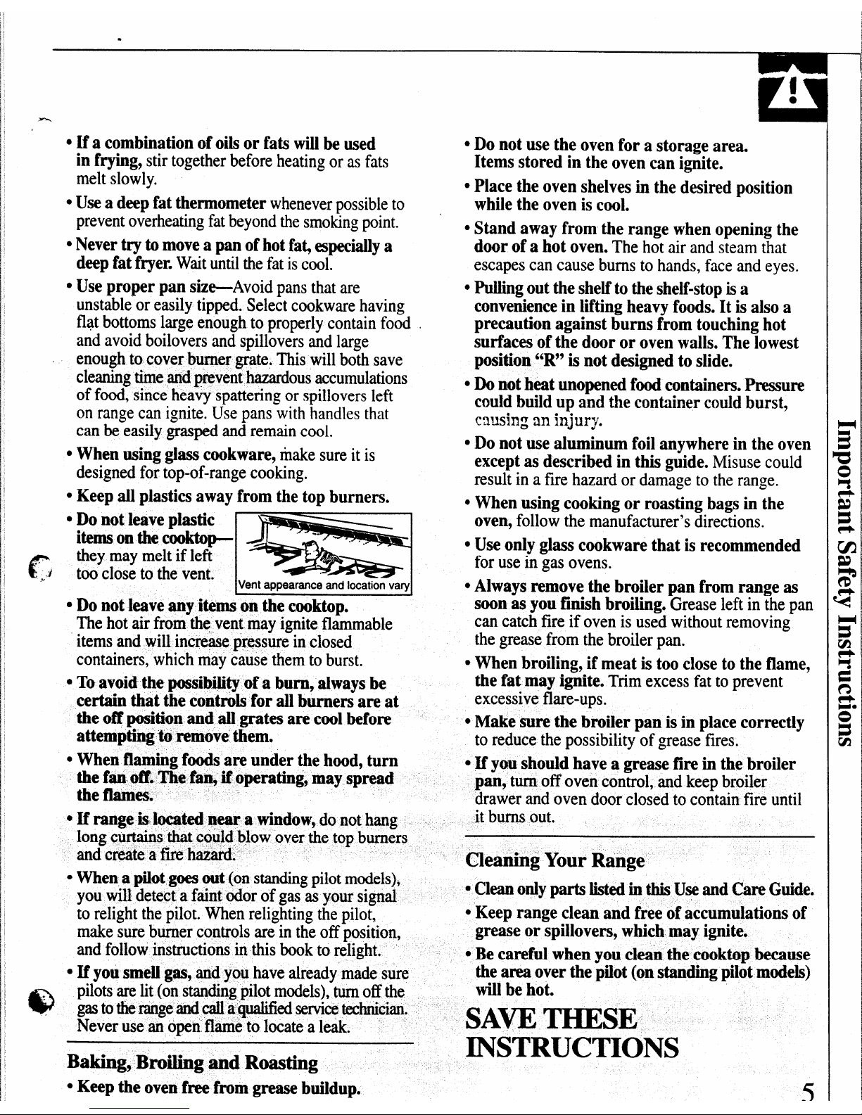
Do not leave pkwtic
items on the cooktop-
r
they
may melt if left
..’
J
too close to the vent.
‘.3
Vent appearance and location vary
● Do not leave any items on the cooktop.
The hot
air from the vent may ignite flammable
items and will increase press&;in closed
containers, which may cause them to burst.
. To avoid @possibility of a bumy always be
certain that the controls for all burners are at
the off position and all grates are cool before
attempting to remove them.
. When flaming fds are under the hood, turn
the f~ off. The fan, if operating, may spread
the flames.
● If range islocatednear a window, do not hang
long curtains that could blow over the top burners
and create a fire hazard.
● When a pilot goes out (on standingpilotmodels),
you will detect a faint odor of gas as your signal
to relight the pilot. When relighting the pilot,
make sure burner controls are in the offposition,
and follow instructions in this book to relight.
. If you
smelI gas? and you have already made sure
@
*
pilots are lit (on standingpilot models), turn off the
gasto therangeandcall
a qualified seMce technician.
Never use an open flame
to locate a leak.
Baking, Broiling and Roasting
●
Keep the oven fkee from grease buildup.
cDo not use the oven for a storage area.
Items stored in the oven can ignite.
QPlace the oven shelves in the desired position
while the oven is cool.
● Stand away from the range when opening the
door of a hot oven.
The hot air and steam that
escapes can cause burns to hands, face and eyes.
. Pulling out the shelf to the shelf-stop is a
convenience in lifting heavy foods. It is also a
precaution against burns from touching hot
surfaces of the door or oven walls. The lowest
position “R” is not designed to slide.
● Do not heat unopened fd containers. Pressure
could build up and the container could burst,
C3US@ an injury.
● Do not use aluminum foil anywhere in the oven
except as described in this guide.
Misuse could
result in a fire hazard or damage to the range.
QWhen using cooking or roasting bags in the
oven,
follow the manufacturer’s directions.
● Use only glass cookware that is recommended
for use in gas ovens.
● Always remove the broiler pan from range as
soon as you finish broiling.
Grease left in the pan
can catch fire if oven is used without removing
the grease from the broiler pan.
● When broiling, if meat is too close to the flame,
the fat may ignite.
Trim excess fat to prevent
excessive flare-ups.
s Make sure the broiler pan is in place correctly
to reduce the possibility of grease fires.
~If you should have a grease fire in the broiler
pan, turnoff
oven control, and keep broiler
drawer and oven door closed to contain fire until
it burns out.
Cleaning Your Range
ccl- o~y pm M inthis
Use and Care Guide.
● Keep range clean and free of accumulations of
grease or spillovers, which may ignite.
● Be careful when you cleai the cooktop because
the area over the pilot (on standing pilo$ models)
will be hot.
SAW THESE
INSTRUCTIONS
<
—
.J
I
Page 6
-——————+
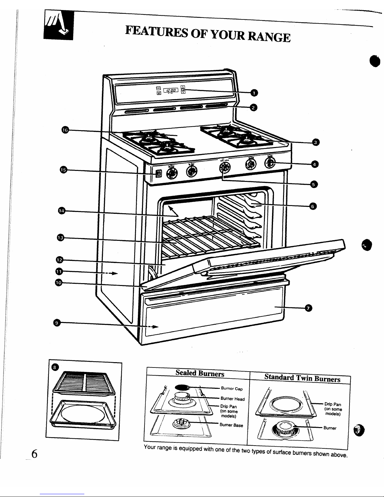
mA~S OF’ YO~ RANGE
——
Ill
I
I
II
llr-
. .
__6
T
Sealed Burners
Standard Twin Burnem
I
~BUrne,c.P
&=?JJ~\ ;:;ead
$-* ,$:::.,
=
Your range is equipped with one of the two types of surface burners shown above.
Page 7
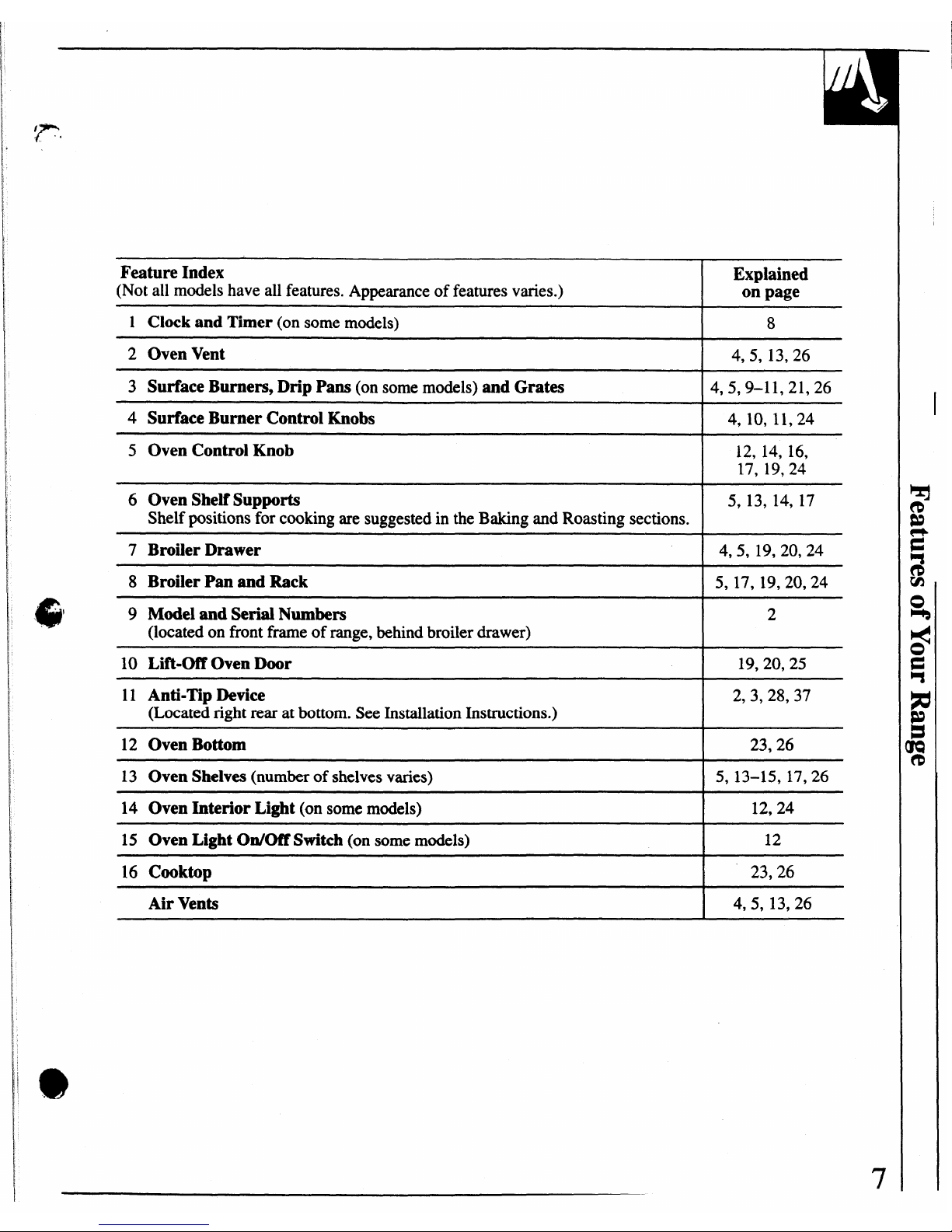
Feature Index
Explained
(Not all models have all features. Appearance of features varies.)
on page
1 Clock and Timer (on some models)
8
2
Oven Vent 4,5, 13,26
3 Surface Burners, Drip Pans (on some models) and Grates 4,5,9–11,21,26
4 Surface Burner Control Knobs
4, 10, 11,24
5 Oven Control Knob
12, 14, 16,
17, 19,24
6 Oven Shelf Supports 5, 13, 14, 17
Shelf positions for cooking are suggested in the Baking and Roasting sections.
7 Broiler Drawer
4,5, 19,20,24
8 Broiler Pan and Rack
5, 17, 19,20,24
9 Model and Serial Numbers
2
(located on frontframeof range, behind broiler drawer)
10 Lift-Of’fOven Door
19,20,25
11 Anti-Tip Device
2,3,28,37
(Locatedrightrearatbottom.See InstallationInstructions.)
12 Oven Bottom
23,26
13 Oven Shelves (numberof shelves varies)
5, 13-15, 17,26
14 Oven Interior Light (on some models)
12,24
15 Oven Light On/Off Switch (on some models)
12
16 Cooktop
23,26
Air Vents
I 4,5,13,26
Page 8
.. ..
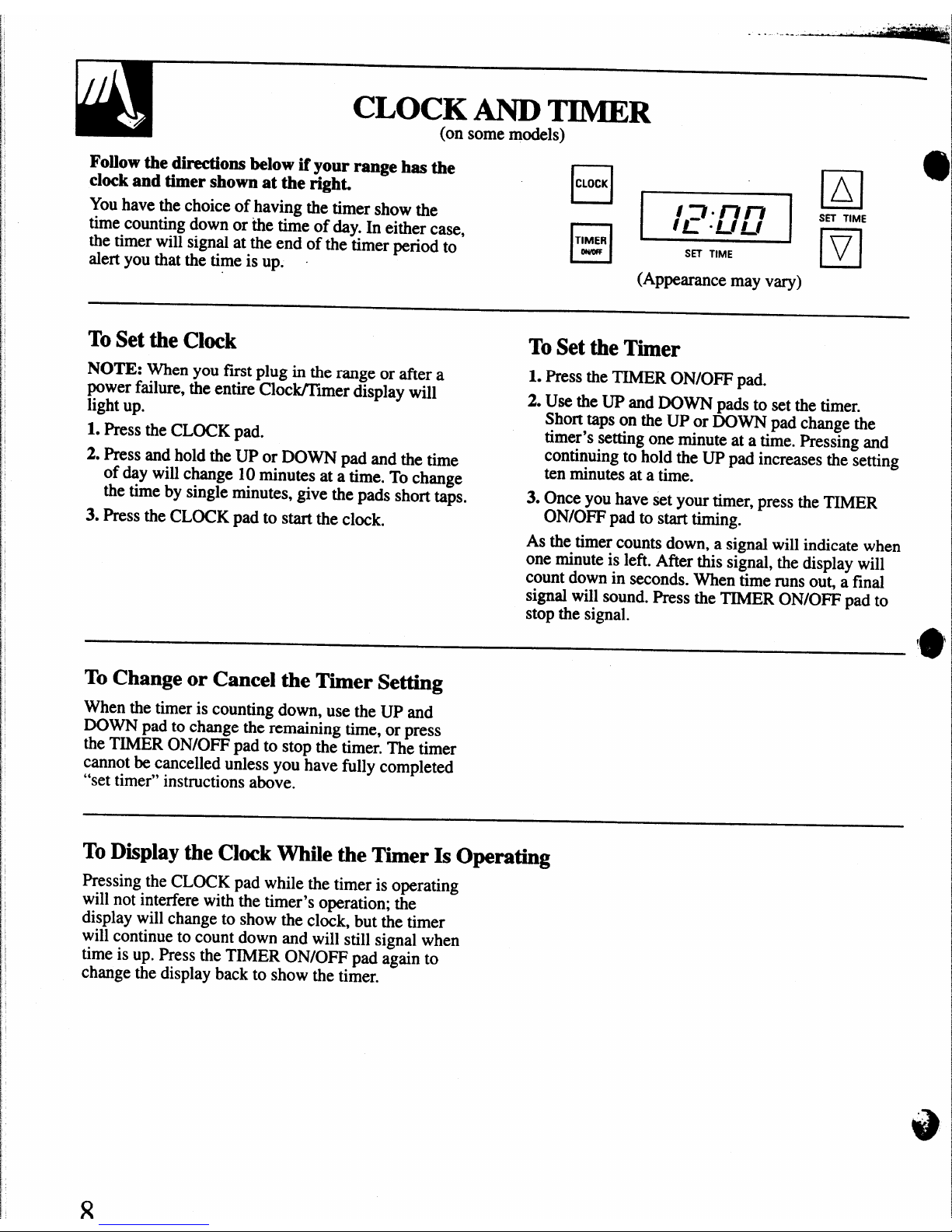
CLOCK AND TIMER
(on somemodels)
Follow the directions below if your range has the
clock and timer shown at the right.
You have the choice of having the timer show the
time counting down or the time of day. In either case,
the timer will signal at the end of the timer period to
;=$[ *
SETTIME
alert you that the time is up.
(Appearancemay vary)
ToSet the Clock
ToSet the
Timer
NOTE: When you fmt plug in the range or aftera
1. PresstheTIMERON/OFF pad.
powerfailure,theentireCloc~lmer display will
light up.
2. Use theUP andDOWN pads to setthetimer.
Shorttapson the UP or DOWN pad change the
1. Pressthe CLOCKpad.
timer’ssetting one minuteata time. Pressing and
2. Pressandhold the UP orDOWN pad and the time
continuingto hold the UP pad increases the setting
of day will change 10 minutes at a time. To change
ten minutes at a time.
-.
the time by single minutes, give the pads
3. Press the CLOCK pad to start the clock.
shortt@.
3. Once you have set your timer, press the TIMER
ON/OFF pad to start timing.
As the timer counts down, a signal will indicate when
one minute is left. After this signal, the display will
count down in seconds. When time runs out, a final
signal will sound. Press the TIMER ON/OFF pad to
stop the signal.
I
e
\
To Change or Cancel the Timer Setting
When the timer is counting down, use the UP and
DOWN pad to change the remaining time, or press
the TIMER ON/OFF pad to stop the timer. The timer
cannot be cancelled unless you have fully completed
“set timer” instructions above.
ToDisplay the Clock While the Timer Is Operating
Pressing the CLOCK pad while the timer is operating
will not interfere with the timer’s operation; the
display will change to show the clock, but the timer
will continue to count down and will still signal when
time is up. Press the TIMER ON/OFF pad again to
change the display back to show the timer.
Page 9
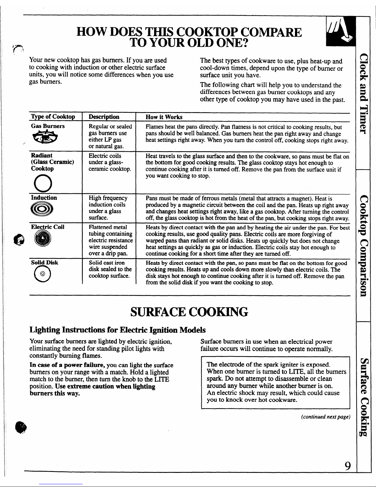
HOW DOES THIS COOKTOP COMPARE
TO YOUR OLD ONE?
Your new cooktop has gas burners. If you are used
The best types of cookware to use, plus heat-up and
to cooking with induction or other electric surface
cool-down times, depend upon the type of burner or
units, you will notice some differences when you use
surface unit you have.
gas burners.
The following chart will help you to understand the
differences between gas burner cooktops and any
other type of cooktop you may have used in the past.
‘Ijq)e of Cooktop
!
Description
I
How it Works
Gas Burners
*
(
Radiant
(Glass Ceramic)
Cooktop
o
Induction
Electric Coil
@
Regular or sealed
gas burners use
either LP gas
or natural gas.
Electric coils
under a glassceramic cooktop.
High frequency
induction coils
under a glass
surface.
Flattened metal
tubing containing
electric resistance
wire suspended
over a drip pan.
Solid Disk Solid cast iron
o
disk sealed to the
@
cooktop surface.
Flames heat the pans directly. Pan flatness is not critical to cooking results, but
pans should be well balanced. Gas burners heat the pan right away and change
heat settings right away. When you turn the control off, cooking stops right away.
Heat travels to the glass surface and then to the cookware, so pans must be flat on
the bottom for good cooking results. The glass cooktop stays hot enough to
continue cooking after it is turned off. Remove the pan from the surface unit if
you want cooking to stop.
Pans must be made of ferrous metals (metal that attracts a magnet). Heat is
produced by a magnetic circuit between the coil and the pan. Heats up right away
and changes heat settings right away, like a gas cooktop. After turning the control
off, the glass cooktop is hot from the heat of the pan, but cooking stops right away.
Heats by direct contact with the pan and by heating the air under the pan. For best
cooking results, use good quality pans. Electric coils are more forgiving of
warped pans than radiant or solid disks. Heats up quickly but does
notchange
heat settings as quickly as gas or induction. Electric coils stay hot enough to
continue cooking for a short time after they are turned off. -
—
Heats by direct contact with the pan, so pans must be flat on the bottom for good
cooking results. Heats up and cools down more slowly than electric coils. The
disk stays hot enough to continue cooking after it is turned off. Remove the pan
from the solid disk if you want the cooking to stop.
SURFACE COOKING
Lighting Instructions for Electric Ignition Models
Your surface burners are lighted by electric ignition,
Surface burners in use when an electrical power
eliminating the need for standing pilot lights with failure occurs will continue to operate normally.
constantly burning flames.
In case of a power failure, you can light the surface
burners on your range with a match. Hold a lighted
match to the burner, then turn the knob to the LITE
position. Use extreme caution when lighting
burners this way.
The electrode of the spark igniter is exposed.
When one burner is turned to LITE, all the burners
spark. Do not attempt to disassemble or clean
around any burner while another burner is on.
An electric shock may result, which could cause
you to knock over hot cookware.
(continued next page)
9
Page 10
. ....--L
SURI?ACE COOKING
(continued)
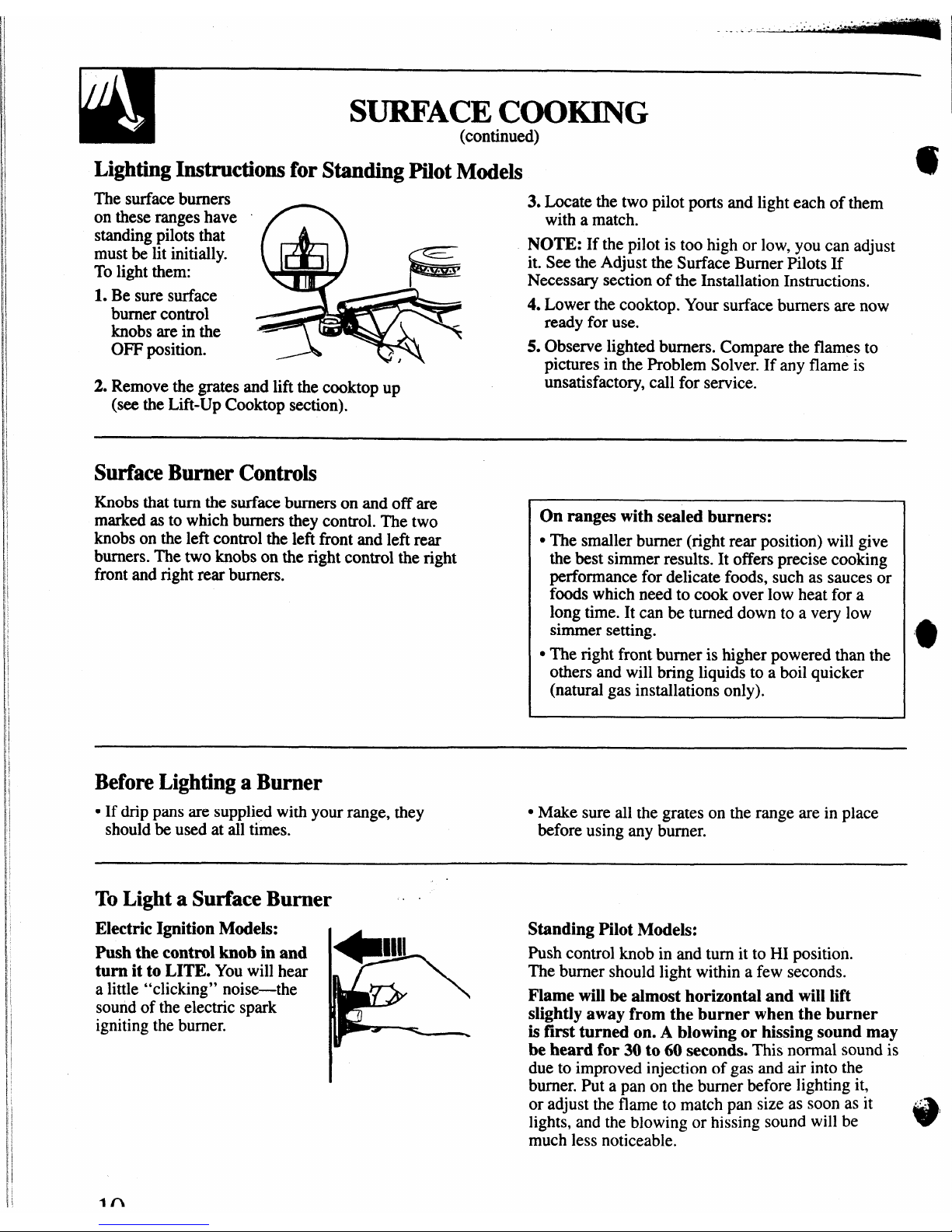
Lighting Instructions for Standing Pilot Models
@
The surface burners
3. Locate the two pilot ports and light each of them
on these ranges have
with a match.
standing pilots that
NOTE: If the pilot is too high or low, you can adjust
must be lit initially.
To light them:
it. See the Adjust the Surface Burner Pilots If
Necessary section of the Installation Instructions.
1. Be sure surface
burner control
4. Lower the cooktop. Your surface burners are now
knobs are in the
ready for use.
OFF position.
5. Observe lighted burners. Compare the flames to
~ictures in the Problem Solver. If any flame is
&
2. Remove the grates and lift the cooktop up
unsatisfactory, call for service. -
(see the Liil-Up Cooktop section).
Surface Burner Controls
Knobs that turn the surface burners on and off are
marked as to which burners they control. The two
knobs on the left control the left front and left rear
burners. The two knobs on the right control the right
front and right rear burners.
On ranges with sealed burners:
. The smaller burner (right rear position) will give
the best simmer results. It offers precise cooking
performance for delicate foods, such as sauces or
foods which need to cook over low heat for a
long time. It can be turned down to a very low
simmer setting.
● The right front burner is higher powered than the
others and will bring liquids to a boil quicker
(natural gas installations only).
Before Lighting a Burner
GIf drip pans are supplied with your range, they
● Make sure all the grates on the range are in place
should be used at all times.
before using any burner.
ToLight a Surface Burner ~
Electric Ignition Models:
Standing Pilot Models:
Push the control knob in and
Push control knob
in and turn it to HI position.
turn it to LITE. You will hear
The burnershould light within a few seconds.
a little “clicking” noise—the
Flame will be almost horizontal and will lift
soundof theelectricspark
1
slightly away from the burner when the burner
ignitingtheburner.
is first turned on. A blowing or hissing sound may
be heard for 30 to 60 seconds. This normalsound is
due to improvedinjection of gas andairintothe
burner.Put a pan on the burner before lighting it,
or adjust the flame to match pan size as soon as it I.’lights, and the blowing or hissing sound will be
*
much less noticeable.
Page 11
-.—...-.
i
4
After Lighting a Burner
● After the burner ignites, turn the knob to adjust the
flame size.
● Check to be sure the burner you turned on is the one
you want to use.
.
Do not operate a burner for an extended period of
time without cookware on the grate. The finish on the
grate may chip without cookware to absorb the heat.
cBe sure the burners and grates are cool before you
place your hand, a pot holder, cleaning cloths or
other materials on them.
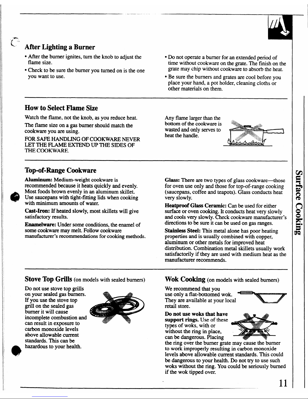
How to Select Flame Size
Watch the flame, not the knob, as you reduce heat.
The flame size on a gas burner should match the
cookware you are using.
FOR SAFE HANDLING OF COOKWARE NEVER
LET THE FLAME EXTEND UP THE STDESOF
THE CoOKWM.
Any flame larger than the ,
bottom of the cookware is
wasted and only serves to
heat the handle.
Top-of-Range Cookware
Aluminum: Medkm-weight cookware is
recommended because it heats quickly and evenly.
Most foods brown evenly in an aluminum skillet.
Use saucepans with tight-fitting lids when cooking
with minimum amounts of water.
Cast-Iron: If heated slowly, most skillets will give
satisfactory results.
Enamelware: Under some conditions, the enamel of
some cookware may melt. Follow cookware
manufacturer’s recommendations for cooking methods.
Glass: There are two types of glass cookware-those
for oven use only and those for top-of-range cooking
(saucepans, coffee and teapots). Glass conducts heat
very slowly.
Heatproof Glass Ceramic: Can be used foreither
surfaceor oven cooking. Itconductsheatveryslowly
andcools veryslowly. Checkcookwaremanufacturer’s
directionsto be sureitcanbeusedon gas ranges.
Stainless Steel: This metal alone has poor heating
properties and is usually combined with copper,
aluminum or other metals for improved heat
distribution. Combination metal skillets usually work
satisfactorily if they are used with medium heat as the
manufacturer recommends.
StOW! TOP Gfi]s (on models with sealed burners)
Do not use stove top grills
on your sealed gas burners.
If you use the stove top
grill on the sealed gas
burner it will cause
incomplete combustion and
can result in exposure to
carbon monoxide levels
above allowable current
standards. This can be
hazardous to your health.
Wok Cooking (on models with sealed burners)
We recommend that you
use only a flat-bottomed wok.
They are available at your local
retail store.
Do not use woks that have
support rings. Use of these
types of woks, with or
without the ring in place,
can be dangerous. Placing
the ring over the burner grate may cause the burner
to work improperly resulting in carbon monoxide
levels above allowable current standards. This could
be dangerous to your health. Do not try to use such
woks without the ring. YOUcould be seriously burned
if the wok tipped over.
11
Page 12
..
..
.-.
USING YOUR OVEN
Before Using Your Oven
Be sure you understand how to set the controls properly. Practie removing
and replacing the shelves while the oven is cool. Read the information and
tips on the following pages. Keep this guide handy where you can refer to
it, especially during the f~st weeks of using your new range.
Lighting Instructionsfor Electric Ignition Models
The oven burner and broil burner are lighted by
electric ignition.
To light the burner, turnthe OVEN CONTROL
knob to the desired temperature.Theburnershould
light within 30-90 seconds. After the oven reachesthe
selected temperate, the oven burnercycles+ff
completely, then on with a full flame-to maintainthe
selected temperature.
Power Outage
CAUTION: DO NOT MAKE ANY A~EMPT TO
OPERATE THE ELECTRIC IGNITION OVEN
DURING AN ELECTRICAL POWER FAILURE.
The oven or broiler cannot be lit during a power
failure. Gas will not flow unless the glow bar is hot.
If the oven is in use when a power failure occurs,
the oven burner shuts off and cannot be re-lit until
power is restored.
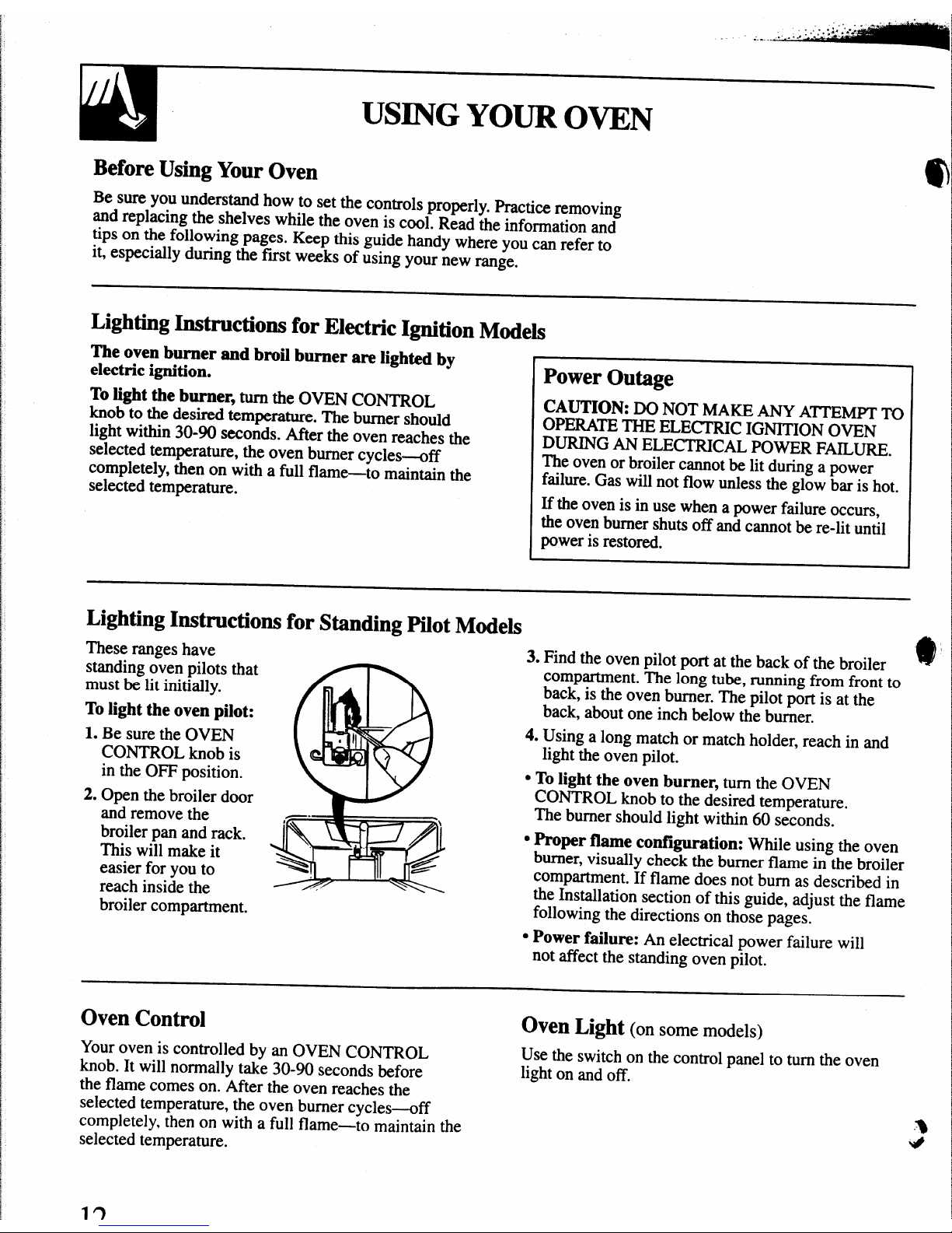
Lighting Instructions for Standing Pilot Models
These ranges have
standing o~en pilots that
must be lit initially.
To light the oven pilot:
1. Be suretheOVEN
CONTROL knob is
in the OFF position.
2. Open the broiler door
and remove the
broiler pan and rack. ‘
This will make it
easier for you to
reach inside the
broiler compartment.
3. Find the oven pilot port at the back of the broiler
compartment. The long tube, running from front to
back, is the oven burner. The pilot port is at the
back, about one inch below the burner.
4.
using a long match or match holder, reach in and
light the oven pilot.
● To light the oven burner, turn the OVEN
CONTROL knob to the desired temperature.
The burner should light within 60 seconds.
● Proper flame contlguration: While using the oven
burner,visually check theburnerflame in the broiler
compartment.If flame does not bum as described in
the Installation section of this guide, adjust the flame
following the directions on those pages.
● Power failure: An electrical power failure will
not affect the standing oven
pilot.
Oven Control
Oven Light
(on some models)
Your oven is controlled by an OVEN CONTROL
Use the switch on the control panel to turn the oven
knob. It will normally take 30-90 seconds before
light on and off.
the flame comes on. After the oven reaches the
selected temperature, the oven burner cycles-off
completely, then on with a full flame-to maintain the
-%
selected temperature.
‘#
Page 13
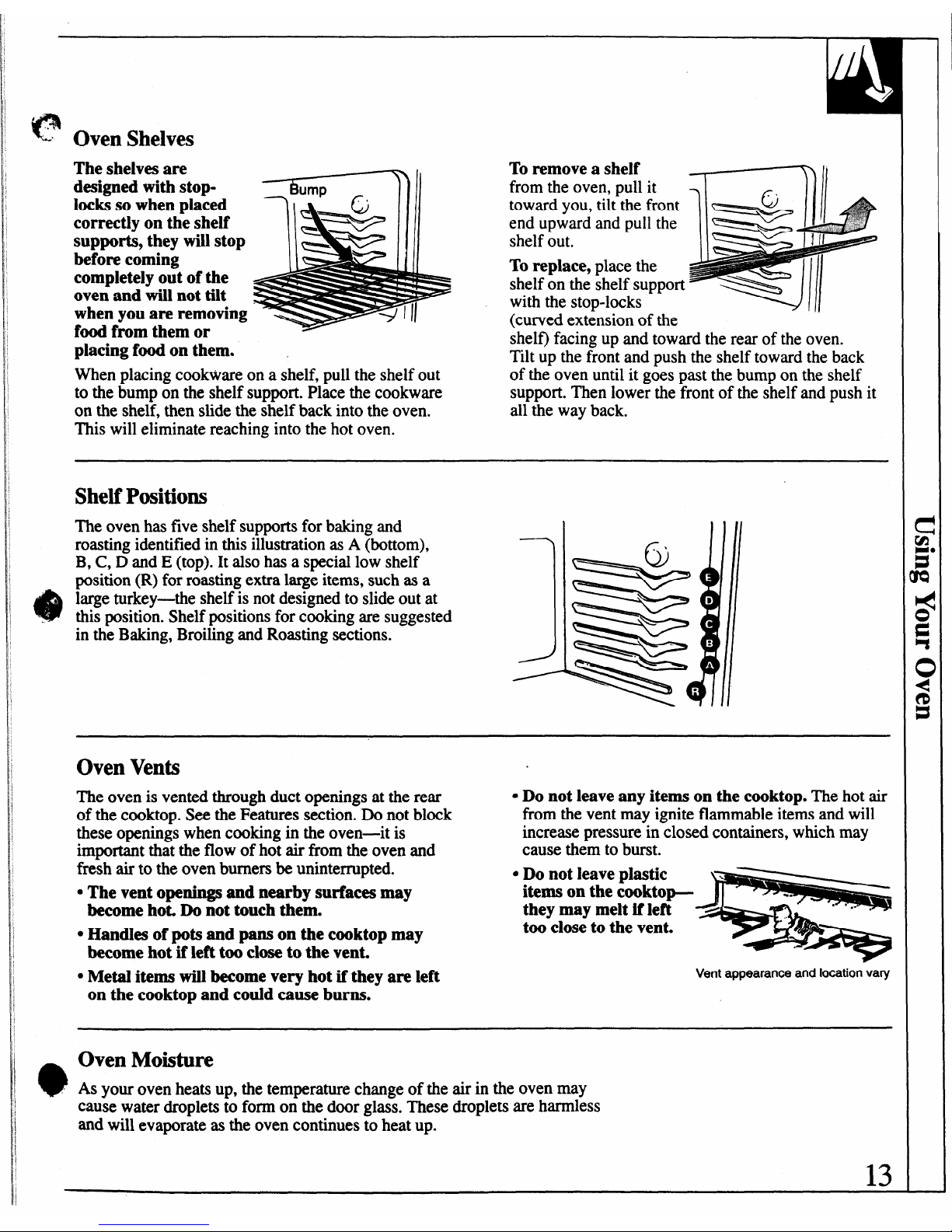
Oven Shelves
The shelves are
designed with stoplocks so when placed
correctly on the shelf
supports, they will stop
before coming
completely out of the
oven and will not tilt
when you are removing
food from them or
placing food on them.
To remove a
shelf
~ II
from the oven, pull it
7
G
. .
toward you, tilt the front
end upward and pull the
111
shelf out.
=====$Z#
To
replace, place the
shelf on the shelf support
with the stop-locks
w
(curved extension of the
shelf) facing up and toward the rear of the oven.
~llt up the front and push the shelf toward the back
When placing cookware on a shelf, pull the shelf out of the-oven until it g;es past the bump on the shelf
to the bump on the shelf support. Place the cookware support. Then lower the front of the shelf and push it
on the shelf, then slide the shelf back into the oven.
all the way back.
This will eliminate reaching into the hot oven.
ShelfPositions
The oven has five shelf supports for baking and
roasting identified in this illustration as A (bottom),
B, C, D and E (top). It also has a special low shelf
position (R) for roasting extra large items, such as a
large turkey-the shelf is not designed to slide out at
this position. Shelf positions for cooking are suggested
in the Baking, Broiling and Roasting sections.
Oven Vents
The oven is vented through duct openings at the rear
● Do not leave any items on the cooktop. The hot air
of the cooktop. See the Features section. Do not block
from the vent may ignite flammable items and will
these openings when cooking in the oven—it is
increase pressure in closed containers, which may
important that the flow of hot air from the oven and
cause them to burst.
fresh air to the oven burners be uninterrupted.
● Do not leave plastic
o
The vent openings and nearby surfaces may
items on the cooktop-
become ho~ Do not touch them.
they may melt if left
too close to the vent.
● Handles of pots and pans on the cooktop may
e
become hot if left too close to the vent.
● Metal items will become very hot if they are left
Vent appearance and locationvafy
on the cooktop and cotdd cause burns.
Oven Moisture
As your oven heats up, the temperature change of the air in the oven may
cause water droplets to form on the door glass. These droplets are harmless
and will evaporate as the oven continues to heat up.
13
Page 14
BAKING
Your oven temperature is controlled very accurately
If you think an adjustment is necessary, see the Adjust
using an oven control system. It is recommended that
the Oven Thermostat section. It gives easy
Do h
you operatetheoven for a numberof
weeks to
Yourse&instructions on how to adjust the thermostat.
become familiar with your new oven’s performance.
How to Set Your Range for Baking
To avoid possible burns, place the shelves in the
2. Check food for doneness at minimum time on
correct position before you turn the oven on.
recipe. Cook longer if necessary.
1. UoW the oven door. Turn the OVEN CONTROL
3. Turn the OVEN CONTROL knob to OFF and
knob to desired temperature.
then remove food.
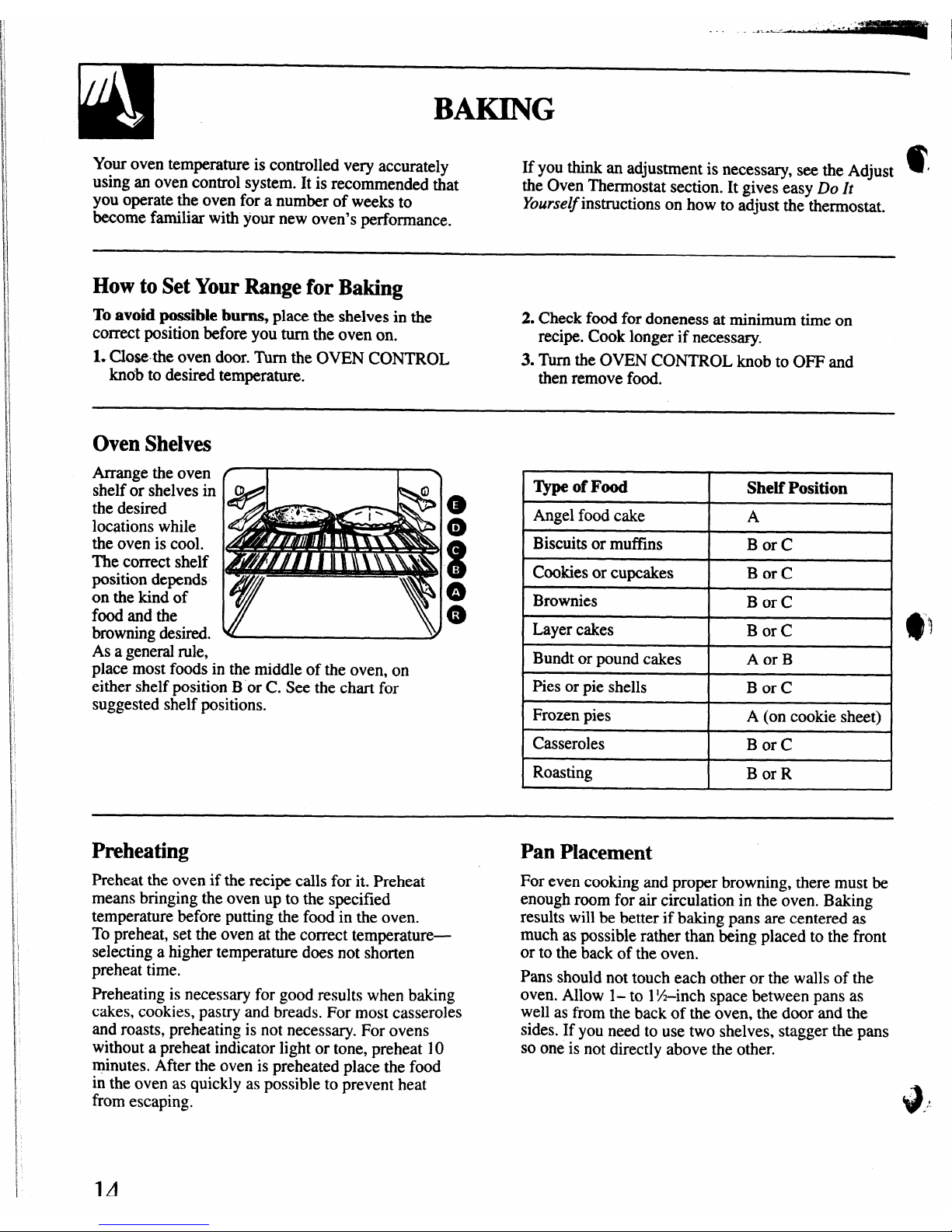
Oven Shelves
Arrange the oven
shelf or shelves in
the desired
locations while
the oven is cool.
The correct shelf
position depends
on the kind of
food and the
browning desired.
I Angel food cake I A
I
] Biscuits ormufl’ins
I BorC
I
Cookies
or cupcakes Bor C
Brownies
Bor C
I Layer cakes
I BorC
I
As a general rule,
Bundt or pound cakes
Aor B
place most foods in the middle of the oven, on
either shelf position B or C. See the chart for
Pies or pie shells
Bor C
suggested shelf positions.
Frozen pies
A (on cookie sheet)
Casseroles Bor C
I Roasting
I Bor R
I
Preheating
Preheat the oven if the recipe calls for it. Preheat
means bringing the oven up to the specified
temperature before putting the food in the oven.
To preheat, set the oven at the correct temperature—
selecting a higher temperature does not shorten
preheat time,
Preheating is necessary for good results when baking
cakes, cookies, pastry and breads. For most casseroles
and roasts, preheating is not necessary. For ovens
without a preheat indicator light or tone, preheat 10
minutes. After the oven is preheated place the food
in the oven as quickly as possible to prevent heat
from escaping.
Pan Placement
For even cooking and proper browning, there must be
enough room for air circulation in the oven. Baking
results will be better if baking pans are centered as
much as possible rather than being placed to the front
or to the back of the oven.
Pans
should not touch each other or the walls of the
oven. Allow 1– to 1X–inch space between pans as
well as from the back of the oven, the door and the
sides. If you need to use two shelves, stagger the pans
so one is not directly above the other.
9.
/!
1A
Page 15

‘Ft
.*
L
.
Baking Chides
When using prepared baking mixes, follow package recipe or
instructions for best baking results.
Cookies
When baking cookies,
flat cookie sheets
(without sides)
Aluminum Foil
I I \
Never entirely cover
(D
4
pb
Q
#
i
produce better-looking
‘%
\
cookies. Cookies
baked in a jelly roll
k
Al
pan (short sides all
&/ %!!%
I
a shelf with aluminum
foil. This will disturb
the heat circulation and
result in poor baking. A
smaller sheet of foil
may be used to catch a
around) may have
y
v
w
w
spillover by placing it
darker edges and pale
on a lower shelf several
or light browning may occur.
inches below the food.
Do not use a cookie sheet so large that it touches the
walls or the door of the oven.
For best results, use only one cookie sheet in the oven
at a time.
dill
.
Pies
Cakes
For best results, bake pies in dark, rough or dull pans When baking cakes, warped or bent pans will cause
to produce a browner, crisper crust. Frozen pies in foil
uneven baking results and poorly shaped products.
pans should be placed on an aluminum cookie sheet
A cake baked in a pan larger than the recipe
for baking since the shiny foil pan reflects heat away
recommends will usually be crisper, thinner and drier
from the pie crust; the cookie sheet helps retain it.
than it should be. If biked in a pan smaller than
recommended, it may be undercooked and batter may
overflow. Check the recipe to make sure the pan size
used is the one recommended.
Baking Pans
Use the proper baking pan. The type of finish on
the pan determines the amount of browning that
will occur.
● Dark, rough or dull pans absorb heat resulting in a
browner, crisper crust. Use this type for pies.
c Shiny, bright and smooth pans reflect heat, resulting
in a lighter, more delicate browning. Cakes and
cookies require this type of pan.
● Glass baking dishes also absorb heat. When baking
in glass baking dishes, the temperature may need to
Q
be~educed by-250F.
Don’t Peek
Setthe timer for the estimatedcookingtime and do
notopen the door to look at your food.Mostrecipes
provideminimumand maximumbakingtimes
such
as “bake 30-40 minutes.”
DO NOT open the door to check until the minimum
time. Opening the oven door frequently during
cooking allows heat to escape and makes baking times
longer. Your baking results may also be tiected.
15
Page 16

.. . . . . ..- .—. -
. .
..
. . .. .
.. . . . . ... ...
ADJUST THE OVEN THERMOSTAT—
DO IT YOURSEW!
e
You may feel that your new oven cooks differently
ToAdjust the Thermostat:
than the one it replaced. We recommendthat you use your new oven for a few weeks to become more
familiar with it, followingthe times given in your
recipes as a guide.
If you think your new oven is too hot or too cold,
you can adjust the thermostat yourself. If you think
it is too ho~ adjustthe thermostatto make it cooler.
If you think it is too cool, adjustthe thermostatto
make it hotter.
We do not recommend the use of inexpensive
—
thermomete~ such as those found in grocery stores,
(appearancemayvary)
to check the temperaturesettingof your new oven.
Pull the OVEN CONTROL knob off the range and
These thermometersmay vary20+0 degrees.
look at the backside.
To make adjustment,loosen (approximatelyone turn),
butdo not completely remove, the two screws on the
back of the knob. With the back of the knob facing
you, hold the outeredge of the knob with one hand
andturnthefrontof the knob with the otherhand.
Toraisetheoven temperature,move the top screw
towardtheright.You’ll heara click foreach notch
you move tie knob. To lower the temperature,move
thetop screw towardthe left. Each click will change
theoven temperatureapproximately 10”F.(Range is A.
plus orminus60”F.from the arrow.)
@
We suggest thatyou make the adjustmentone click
fromtheoriginal setting andcheck oven performance
beforemakinganyadditionaladjustments.
Aftertheadjustmentis made, retightenscrews so they
aresnug,butbe careful not to overtighten. Re-install
knob on rangeand check performance.
Page 17

P
K.
‘.
.
$,
0
..
ROASTING
Roasting is cooking by dry heat. Tender meat or
Roasting is really a baking procedure
used for meats.
poultry can be roasted uncovered in your oven.
Therefore the oven controls are set for Baking.
Roasting temperatures, which should be low and
(You may hear a slight clicking sound indicating the
steady, keep spattering to a minimum. oven is working properly.)
The oven has a special
low shelf (R) position
just above the oven
bottom. Use it when
extra cooking space is
needed, for example,
when roasting a large
turkey. The shelf is not
designed to slide out at
this position.
Most meats continue to cook slightly while standing
after being removed from the oven. Recommended
standing time for roasts is 10 to 20 minutes. This
allows roasts to firm up and makes them easier to
carve. Internal temperature will rise about 5° to 10“F.
If you wish to compensate for temperature rise,
remove the roast from the oven when its internal
temperature is 5° to 10*F.less than temperature
shown in the Roasting Guide.
Remember that food will continue to cook in the hot
oven and therefore should be removed when the
desired internal temperature has been reached.
small size roast
(3 to 5 lbs.) and at
(R) position for
larger roasts.
1. Position oven shelf
JI*
3. Turn the OVEN CONTROL knob to the desired
at (B) position for
temperature. See the Roasting Guide for
temperatures and approximate cooking times.
7
%@
4. When Roasting is finished, turn the OVEN
Q
CONTROL knob to OFF and then remove the food
!=== a
~
from the oven.
2. Check the weight of the roast. Place the meat -fat-side-up or the poultry breast-side-upon the
roasting rack in a shallow pan. The melting fat will
baste the meat. Select a pan as close to the size of
meat as possible. (Broiler pan with rack is a good
pan for this.)
Dual Shelf Cooking
This allows more than one f~ to be cooked at the same time. For example:
While roasting a 20-lb. turkey on shelf position R, a second shelf (if so
equipped) may be added on position D so that scalloped potatoes can be
cooked at the same time. Calculate the total cooking time to enable both
dishes to complete cooking at the same time. Allow 15-20 minutes of
additional cooking time for the potatoes.
Use of Aluminum Foil
You can use aluminum foil to line the broiler pan.
This makes clean-up easier when using the pan for
marinating, cooking with fruits, cooking heavily
cured meats or basting food during cooking. Press
the foil tightly around the inside of the pan.
(continued next page)
17
Page 18

.
ROASTING
(continued)
Questions and A~wers
Q. Is it necessary to check for doneness with a
Q.
Do I need to preheat my oven each time I cook
meat thermometer?
a roast or poultry?
A. Checking the finished internal temperature at the
completion of cooking time is recommended.
Temperatures are shown in Roasting Guide. For
roasts over 8 lbs., check with thermometer at halfhour intervais after half the time has passed.
Q. Why is my mast crumbling when I try to
carve it?
A. Roasts are easier to slice if allowed to cool 10 to
20 minutes after removing from oven. Be sure to
cut across the grain of the meat.
A. It is not necessary to preheat your oven.
Q. When buying a roast, are there any special tips
that would help me cook it more evenly?
A. Yes. Buy a roast as even in thickness as possible,
or buy rolled roasts.
Q. Can I seai the sides of my foil “tent” when
roasting a turkey?
A. Sealing the foil will steam the meat. Leaving
it unsealed allows the air to circulate and brown
the meat.
ROASTING GUIDE
Frozen Roasts
Frozen roasts of beef, pork, lamb, etc., can be started
Make sure poultry is thawed before roasting.
without thawing, but allow 15 to 25 minutes per pound
Unthawed poultry often does not cook evenly.
additional time (15 minutes per pound for roasts under Some commercial frozen poultry can be cooked ..
5 pounds, more time for la&er roasts.)
Meat
Tender cuts; rib, high quality sirloin
tip, rump or top round*
Lamb leg or bone-in shoulder*
Veal shoulder, leg or loin*
Pork loin, rib or shoulder*
Ham, precooked
Poultry
Chicken or Duck
Chicken pieces
Turkey
Oven
Temperature
325°
325°
325°
325°
325°
325°
350°
325°
Doneness
Rare:
Medium.
Well Done:
Rare:
Medium
Well Done:
Well Done:
Well Done:
To Warm:
Well Done:
Well Done:
Well Done:
successfidly without thawing. Follow directions
@
J]
given on package label. -
Approximate Roasting Time
in Minutes per Pound
3 to 5 lbs.
24-35
35-39
39-45
21-25
25–30
30-35
35-45
35-45
6 to 8 Ibs.
18-25
25-31
31–33
20-23
24-28
28–33
30-40
30-40
18-23 minutes per pound (any weight)
3 to 5 Ibs.
Over
5 lbs.
35-40 30-35
35-40
10 to 15 lbs.
Over 15 lbs.
16-22 12–19
*For boneless rolled roasts over 6 inches thick, add 5 to 10 minutes per pound to times given above.
Internal
I’emperature “F.
140°-15007
150°-1600
1700–185°
140°-1500~
150°-1600
170°-1850
1700-180°
1700-180°
115°-1250
185°-1900
185°–1900
In thigh:
185°–1900
TThe U.S. Department of Agriculture says “Rare beef is popular, but you should know that cooking it to only 140”F. means
some food poisoning organisms may survive.” (Source: Safe Food Book Y
. our Kitchen Guide. USDA Rev. June 1985.)
Page 19

BROILING
Broiling is cooking food by direct heat from above the Both the oven and broiler compartment doors
food. Most fish and tender cuts of meat can be broiled. should be closed during broiling.
Follow these directions to keep spattering and smoking
Turn most foods once during cooking (the exception
to a minimum.
is thin fillets of fish; oil one side, place that side down
Your range has a compartment below the oven for on broiler rack and cook without &ming until done).
broiling. A specially designed broiler pan and rack Time foods for about one-half the total cooking time,
allow dripping fat to drain away from the food and turn food, then continue to cook to preferred doneness.
keeps it away from the high heat of the gas flame.
1. Youcan change the distance of the food from the
heat source by positioning the broiler pan and rack
on one of three shelf positions in the broiler
compartment-A (bottom of broiler compartment),
B (middle) and C (top).
2. Preheating the broiler or oven is not necessary and
can produce poor results.
3. If meat has fat or gristle around the edge, cut
vertical slashes through it about 2 inches apart;
do not cut into the meat. We recommend that you
trim fat to prevent excessive smoking, leaving a
layer about 1/8 inch thick.
4. Arrange the food on the rack and position the
broiler pan on the appropriate shelf in the oven or
broiling compartment. Placing food closer to the
flame increases exterior browning of the food, but
also increases spattering and the possibility of fats
and meat juices igniting.
5. Close the oven and broiler compartment door.
6. Turn the OVEN CONTROL knob to BROIL.
7. Turn OVEN CONTROL knob to OFF. Remove the
broiler pan from the broiler compartment and serve
food immediately. Leave the pan outside the range
to cool.
Use of Aluminum Foil
Youcan use aluminum foil to line your broiler pan and
broiler rack. However, you must mold the foil tightly
to the rack and cut slits in it just like the rack.
Without the slits, the foil will prevent fat and meat
juices from draining to the broiler pan. The juices
could become hot enough to catch on fire. If you do
not cut the slits, you are frying, not broiling.
Questions and Answers
Q. When broiling, is it necessary to always use a
Q. Why are my meats not turning out as brown as
rack in the pan?
they should?
A. Yes. Using the racksuspends the meatover the
A. Check to see if you areusing therecommended
pan.As themeatcooks, thejuices fall intothe pan,
shelf position. Broil forthe longest periodof time
thuskeeping meatdrier.Juices areprotectedby the
indicated in the Broiling Guide. Turnthe food only
rackandstaycooler, thus preventingexcessive
once during broiling.
spatterand smoking.
Q. Should I salt the meat before broiling?
A. No. Salt draws out thejuices and allows them to
evaporate. Always salt after cooking. Turn the
meat with tongs; piercing the meat with a fork also
allows juices to escape. When broiling poultry or
fish, bfish each side-often with butte~ - “
19
Page 20

BROILING GUIDE
The oven and broiler compartment doors must be
. Ifdesired,marinatemeatsorchicken beforebroiling.
11
closed during broiling.
Or
brushwithbarbecuesaucelast5 to 10minutesonly.
● Always use the broiler pan and rack that comes with
● When arranging the food on the pan, do not let fatty
your range. It is designed to minimize smoking and
edges hang over the sides because dripping fat could
spattering by trapping the juices in the shielded lower
soil the oven.
part of the pan.
—.. .
sFor steaks and chops, slash the fat evenly around the
outside edges of the meat. To slash, cut crosswise
through the outer fat surfacejust to the edge of the
meat. Use tongs to turn the meat over to prevent
piercing the meat and losing juices.
Quantity
and/or
Food
Shelf
Thickness
Position
Bacon
l/2-lb.
B
(about 8 thin slices)
Ground Beef
l-lb.
(4 patties)
WellDone
A
1/2 to 3/4-inch thick
Beef Steaks
Rare
l-inch thick
Medium
B
(1-l% lbs.)
Well Done
B
A
Rare
1%-inchthick
B, C
Medium
(2-2% lbs.)
Well Done
B
A
Chicken
1 whole
A
(2 to 2%-lbs.),
split lengthwise
Bakery
Products
Bread(Toast)or
2-4 slices
Toaster Pastries
c
1
pkg.(2)
EnglishMuffins
2-split
c
Lobster Tails
2-4
A
(6 to 8-02.each)
Fish
l-lb. fillets 1/4 to
B, C
l/2-inch thick
Ham slices
l-inch thick
B
Precooked
Pork Chops
2 (1/2-inch)
Well Done
B
2 (l-inch thick),
B
about 1lb. -
Lamb Chops
Medium
2 (l-inch)
Well Done
B
about 10-12
OZ.
B
Medium
2 (1X-inch),
Well Done
B
about 1lb.
B
Wieners,
1-lb. pkg. (10)
B, C
similar precooked
sausages,bratwunt
1
1st Side
Minutes
● ‘l-he broiler compartment does not need to be
preheated. However, for very thin foods, or to
increase browning, preheat if desired.
● Frozen steaks can be broiled by positioning the shelf
at the next lowest shelf position and increasing the
cooking time given in this guide 1%times per side.
10-11
9
12
13
10
12-15
25
30-35
2-3
3-5
13-16
5
8
10
13
8
10
10
17
6
2nd Side
Minutes
Comments
3
Arrangein single layer.
4-5
Space evenly. Up to 8 patties take
about same time.
7
Steaks less than l-inch cook through
5-6
before browning.
8-9
Pan frying is recommended.
6-7
Slash fat.
10-12
1-18
25-30
Reduce times about 5 to 10 minutes
per side for cut-up chicken. Brush each
side with melted butter. Broil with skin-
side-down first.
1/2-1
Space evenly. Place English muffins
cut-side-up and brush with butter,
if desired.
Do not
Cut through back of shell, spread
turn over.
open. Brush with melted butter
before broiling and after half of
broiling time.
5
Handle and turn very carefully. Brush
with lemon butter before and during
cooking, if desired. Preheat broiler to
increase browning.
8
Increase times 5 to 10 minutes per side
for 1X-inch thick or home cured.
4-5
Slash fat.
9-12
4-7
Slash fat.
10
12-14
4
4>
1–2
If desired, split sausages in half
lengthwise; cut into 5 to 6-inch
pieces.
m
Page 21

B
.1
s-”-’
CARE AND CLEANING
Proper care and cleaning are important so your range will give you efficient
and satisfactory service. Follow these directions carefully in caring for it to
help assure safe and proper maintenance.
BE SURE ELECTRICAL POWER IS DISCONNECTED BEFORE
CLEANING ANY PART OF YOUR RANGE.
ktll
-.
<
,.
CAUTION: DO NOT OPERATE THE BURNER WITHOUT ALL BURNER PARTS AND DRIP PANS
(IF SO EQUIPPED) IN PLACE.
Sealed Burner Assemblies (On some models)
Grate
(onsomemodels)
‘Ihm all controls OFF before removing burner
parts and
drip pans (if so equipped).
The burner grates, caps, burner heads and drip
pans (if so equipped) can be lifted off, makingthem
easy to clean.
The electrode of the
Electrode >
spark igniter is exposed.
When one burner is turned
to LITE, all the burners
spark. Do not attem~t to
d~sassemble or cle& around a~
/
burner while another burner is on. An electric
shock may result, which could cause you to knock
over hot cookware.
~UrnW (%PS (on sealedburnersonly)
Burner B= (onsealed burners only)
Lift off when cool. Wash burner
The burner base (the part of the
caps in hot, soapy water and rinse
burner fastened to the cooktop) may be
with clean water. If desired, soak up to
cleaned with a soft brush and a mild
30 minutes and scour with a plastic
cleanser. Clean all food residues from
scouring pad to remove burned-on food particles.
around spark electrode. Do not use steel
Dry them in a warm oven or with a cloth-
WOO1;small bits of steel wool will short out the
do not reassemble them wet.
electrode. Rinse well.
(continued next page)
21
Page 22

-
CARE AND CLEANING
(continued)
Burner HWNIS(onseakxiburners only)
Q
The holes in the burners of your range, and the spark
For more stubborn stains, use a
electrodes, must be kept clean at all times for proper
cleanser like Soft Scrub@brand or
ignition and an even, unhampered flame.
Bon Ami” brand. Rinse well to remove
YN should cIean the burner heads routinely,
anytraces of the cleanser that might
especially tier bad spillovers, which could clog these
clog the burner openings. Do not use steel wool
holes. W@ off burner heads. If heavy spillover
because it will clog the burner openings and scratch
occurs, remove burner heads from range.
the burners. If the holes become clogged, clean them
Remove the burner grate and burner cap. Then lift the
with a sewing needle or twist tie.
burner head straight up.
Before putting the burner head back, shake out
To get rid of burned-cm food, soak the burner head
excess water and dry it thoroughly by setting it in a
upside-down in a solution of mild liquid detergent and
warm oven for 30 minutes. Then place it back in the
hot water. Soak the burner head for 20 to 30 minutes.
range, making sure the pin in the burner base goes in
If the food doesn’t rinse off completely, scrub it with
the hole in the burner head, and that the burner heads
soap and water and a soft brush or plastic scouring pad.
are properly seated and level.
?
CAUTION: DO NOT OPERATE THE BURNER WITHOUT ALL BURNER PARTS AND DRIP PANS
(IF SO EQUIPPED) IN PLACE.
I
I
J
Standard M Burners (on some models)
— Grate
-~=m-,s)
/lQ\
m
A
o
f>
Surface Burner
. .
‘L ‘
On models with standard twin burners, the cooktop
lifts up forjeasy access.
‘Ihm all controls
OFF before removing burner
parts and drip pans (if so equipped).
The burner grates and drip pans (if so equipped)
can be lifted off, making them easy to clean.
The holes in the surface burners of your range must
be kept clean at all times for proper ignition and an
even, unhampered flame.
You should clean the surface burners routinely,
especially after bad spillovers, which could clog
a
;
these holes. Wipe off surface burners. If heavy
)
spillover occurs, remove the surface burners from
range. Burners lift out for cleaning. Lift up the
cooktop and then lift out the surface burners.
To remove burned-on food, soak the surface burner
in a solution of mild liquid detergent and hot water.
Soak the surface burner for 20 to 30 minutes. For
more stubborn stains, use a cleanser like Soft Scrub@
brand or Bon Ami@brand. Rinse well to remove any
traces of the cleanser that might clog the surface
burner openings. Do not use steel wool because it will
clog the surface burner openings and scratch the
surface burners. If the holes become clogged, clean
them with a sewing needle or twist tie.
Before putting the surface burner back, shake out
excess waterand then dryit thoroughly by setting it in
awarmoven for 30 minutes.Then place it back in the
range,makingsureit is properly seated and level.
Dfip Pans (on some mode]s)
Remove the grates and /_-
,J
To get rid of burned-on food, place them in a
covered container (or plastic bag) with 1/4
cup
ammonia to loosen the soil. Then scrub with a
soap-filled scouring pad if necessary.
&
lift out the
drip pans.
Drip pans can be cleaned
in dishwasher or by hand.
]-J
22
—
Page 23

n
..
Burner Grates
Lift out when cool. Grates should be washed regularly
and, of course, after spillovers. Wash them in hot,
soapy water and rinse with clean water. After
cleaning, dry them thoroughly by putting them in a
warm oven for a few minutes. Don’t put the grates
back on the range while they are wet. When replacing
the grates, be sure they’re positioned securely over the
burners.
To prevent rusting on cast iron grates, apply a light
coating of cooking oil on the bottom of the grates.
To get rid of burn@-on food, place the grates in a
covered container (or plastic bag) with 1/4 cup
ammonia to loosen the soil. Then scrub with a soapfilled scouring pad if necessary.
Although they’re durable, the grates will gradually
lose their shine, regardless of the best care you can
give them. This is due to their continual exposure to
high temperatures.
Do not operate a burner for an extended period of
time without cookware on the grate. The finish on the
grate may chip without cookware to absorb the heat.
Cooktop Surface
To avoid damaging the porcelain enamel surface
of the cooktop and to prevent it from becoming
dull, clean up spills right away. Foods with a lot of
acid (tomatoes, sauerkraut, fruit juices, etc.) or foods
with high sugar content could cause a dull spot if
allowed to set.
When the surface has cooled, wash and rinse. For
other spills such as fat smatterings, etc., wash with
soap and water once the surface has cooled. Then
rinse and polish with a dry cloth.
Be carefhl when you clean the cooktop because
the area over the pilot will be hot (on models with
standing pilots).
Do not store flammable materials in an oven or
near the cooktop. Do not store or use combustible
materials, gasoline or other flammable vapors and
liquids in the vicinity of this or any other appliance.
Oven Bottom
The oven bottom has a porcelain enamel finish.
To make cleaning easier, protect the oven bottom
from excessive spillovers by placing a cookie sheet
on the shelf below the shelf you are cooking on. You
can use aluminum foil if you do not cover the whole
shelf. This is particularly important when baking a
fruit pie or other foods with a high acid content. Hot
fruit fillings or other foods that are highly acidic
(such as milk, tomatoes or sauerkraut, and sauces with
vinegar or lemon juice) may cause pitting and damage
to the porcelain enamel surface and should be wiped
up immediately.
If a spillover does occur on the oven bottom,
allow the oven to cool first.
Frequent wipings with mild soap and water
(particularly after cooking meat) will prolong the time
between major cleanings. Rinse thoroughly. Soap left
on the oven bottom can cause stains.
For heavy soil, use an abrasive cleaner or a soapfilled scouring pad. A commercialoven cleaner may
.also be used, following the package directions.
(continued next page)
23
Page 24

... .a.
CARE AND CLEANING
(continued)
Oven Light Btib (onsomemodels)
The light bulb is located in the upper left comer
of the oven. Before replacing your oven light bulb,
disconnect the electrical power to the range at the
main fuse or circuit breaker panel or unplug the
range from the electrical outlet. Let the bulb cool
completely before removing it. Replace the bulb with
a 40 watt appliance bulb only. Do not touch a hot bulb
with a damp cloth as the bulb will break.
Control Panel and Knobs
It’s a good idea to wipe the control panel after each
The control knobs may ~
use of the oven. Clean with mild soap and water or
be removed for easier
vinegar and water, rinse with clean water and polish
cleaning. To remove knob,
dry with a sofl cloth.
pull it straight off the
Do not use abrasive cleansers, strong liquid cleaners,
stem. If knob is difficult
plastic scouring pads or oven cleaners on the control
to remove, place a towel ~
panel-they will damage the finish. A 50/50 solution
or dishcloth between the knob and control panel and
of vinegar and hot water works well.
pull gently. Wash the knobs in soap and water or a
vinegar and hot water solution but do not soak.
Metal parts can be cleaned with soap and water.
Do not use steel wool, abrasives, ammonia, acids
@)
or commercial oven cleaners. Dry with a soft cloth.
“~
~1
Removable Broiler Drawer (onsome models)
To remove:
1. When the broiler is cool, remove the rack and pan.
2. Pull the broiler drawer out until it stops, then push
it back in about one inch.
3. Grasp the handle, lift and pull broiler drawer out.
Clean the broiler drawer with hot soapy water.
To replace:
Hold the broiler drawer in the raised position as you
slide it partway into the range. Then lower the drawer
and push it completely closed.
Broiler Pan and Rack
After broiling, remove the broiler pan. Remove the
rack from the pan. Carefully pour out grease from the
pan into a proper container. Wash and rinse the broiler
pan and rack in hot water with a soap-filled or plastic
scouring pad.
If food has burned on, sprinkle the rack with detergent
while hot and cover with wet paper towels or a
dishcloth. Soaking the pan will removeburned on foods.
Both the broiler pan
and rack can also be
cleaned in the dishwasher.
Do not store a soiled
broiler pan and rack
anywhere in the range.
Page 25

The oven door is removable but it is heavy. You may
need help removing and replacing the door.
To remove the door,
open it a few inches to
the special stop
position that will hold
the door open. Grasp
firmly on each side
and lift the door
straight up and off
the hinges.
NOTE: Be careful
not to place hands
between the hinge
and the oven door
frame as the hinge
could snap back and
pinch fingers.
TO CLEAN THE DOOR:
(Do not immerse door in water.)
Inside of door:
. Allow to cool before cleaning. For light soil, wipe
frequently with mild soap and water (especially after
cooking meat). This will prolong the time between
major cleaning. Rinse thoroughly.
NOTE: Soap left on the oven door causes
additional stains when the oven is reheated.
. For heavy soil, choose an oven cleaner and follow
label instructions. Rinse well.
Outside of door:
s Use soap and water to thoroughly clean the top,
sides and front of the oven door. Rinse well.
You may also use a glass cleaner to clean the glass
on the outside of the door.
To replace the door, make sure the hinges are in the
● Spillage of marinades, fruit juices, tomato sauces
and basting materials containing acids may cause
special stop position. Position the slots in the bottom
discoloration and should be wiped up immediately.
of the door squarely over the hinges. Then lower the
When surface is cool, clean and rinse.
door slowly and evenly over both hinges at the same
time. If hinges snap back against the oven frame, pull
● Do not use oven cIeaners, cleansing powders or
[
@
em back out.
harsh abrasives on the outside of the door.
Porcelain Oven Interior
With proper care, the porcelain enamel intenor will
retain its attractive finish for many years.
Soap and water will normally do the job. Heavy
spattering or spillovers may require cleaning with a
mild abrasive cleanser. Soapy, wet pads may also be
used. Do not allow food spills with a high sugar or
acid content (such as milk, tomatoes, sauerkraut, fruit
juices or pie filling) to remain on the surface. They
may cause dull spots even after cleaning.
Household ammonia may make the cleaning job
easier. Place 1/2 cup ammonia in a shallow glass pan
and leave in a cold oven overnight. The ammonia
fumes will help loosen the burned-on grease and food.
When necessary, you may use a commercial oven
cleaner. Follow the package directions.
Cautions about using spray-on oven cleaners:
s
Be careful where the oven cleaner is sprayed.
s Do not spray oven cleaner on the electrical controls
and switches (on some models) because it could
cause a short circuit and result in sparking or fire.
● Do not allow a film from the cleaner to remain on
the temperature sensing bulb-it could cause the
oven to heat improperly. (The bulb is located at the
rear of the oven.) Carefully wipe the bulb clean after
each oven cleaning, being careful not to move the
bulb as a change in its position could affect how the
oven bakes.
. Do not spray any oven cleaner on the outside oven
door, handles or any exterior surface of the oven,
cabinet or painted surfaces. The cleaner can damage
these surfaces.
(continued next page)
—
Page 26

... .
.,
..-. .
CARE AND CLEANING
(continued)
Oven Shelves
Clean the shelves with an abrasive cleanser or
steel wool. After cleaning, rinse the shelves with
clean water and dry with a clean cloth.
Lift-up Cooktop (onmodelswithstandard twin burners)
Clean the
area under the cooktop often. Built-up soil,
especially grease, may catch on fire.
To make cleaning easier, the cooktop may be
lifted up.
To raise the cooktop:
1. Be sure the burners are turned off.
2. Remove the grates.
3. Grasp the two front burner wells and lift up.
Some models have dual support rods that will hold the
cooktop up while you clean underneath it.
After cleaning under the cooktop
with ho~
soapy water and a clean cloth, lower the cooktop.
Be carefil not to pinch your fingers. Lower the
cooktop gently to avoid blowing out pilot flames (on
standing pilot models).
e
\
—-
Oven Air Vents
Never block the vents (air openings) of the range.
They provide the air inlet and outlet that are
necessary for the range to operate properly with
correct combustion. Air openings are located at the
rear of the cooktop, at the top and bottom of the oven
door, and at the bottom of the ,range,under the kick
panel, storage drawer or broiler drawer (depending on
the model).
Vent appearance and location vary
Page 27

FOR YOUR SAFETY
If
you smell gas:
1. Open windows.
2. Don’t touch electicd switches.
3. Extinguish any open flame.
4. Immediate& call your gas supplier.
FOR YOUR SAFETY
Do not store or use combustible
materials, gasoline or other flammable
vapors and liquids in the vicinity of this
or any other appliance.
BEFORE YOU BE61U
Read these instructions completely and
carefully.
IMPORT~: Save these instructions
for the local electrie~ inspecto~s use.
INfl-R Leave these instructions
with the appliance after installation is
Completed.
CONS~E~ Keep this Use and Care
Guide and the Installation Instructions
for fiture use.
This appliance must be properly grounded.
WARBIIH6
Improper installation, adjustment,
alteration,
service or maintenance can
cause injury or property damage. Refer
to this guide. For assistance or addition~
information, consult a qualitied
installer,
service agency, manufacturer (dealer) or
the gas supplier.
I WTION
I
!’
Do not attempt to operate the oven
= Of this range during a power &ilure
(Electric Ignition models only).
I
Remove all packing material and
literature from oven before connecting
gas and electic~ supply to range.
IMIEHSIOMS AND CLEARANCES
Provide adequate clearmces between the range
and adjacent combustible surfaces.
Depth with door closed
I
See chart
below for
height
I
7
Depth with
‘\
-\
door open:
\
\
\
\
46%”
\
H**
~d-
>-””””
Range Height
40” LGBIIQ
44” LGB126
dew LGB146
LGB156
n Ill n r m
18”
m
GyJlm on
altherMa
ofrange
TO cabinet,? ‘
Mow oook-
top
and ●t
~~ t)@k
(continued next page)
I
27
Page 28

IM?ORTAHT SAFETY INSTRUCTIONS
Installation of this range must conform with
local codes, or in the absence of local codes,
with the National Fuel Gas Code, ANSI
2223.1, latest edition. In Canada, installation
must conform with the current Natural Gas
InstaUation Code, CAN/CGA-B149. 1 or the
current Propane Installation Code, CiKN/CGAB149.2, and with local codes where applicable.
T’Msrange
has been design-certified by the
AmericanGasAssociationaccording toANSI221.1,
latest edition and Canadian Gas Association
according to CAN/CGA-l.l latest edition. Aswith
any appliance using gas and generating heag
there are certain safety precautions you should
follow.Youwill find these precautions in the
Important Safety Instructions in the front of this
guide. Read them carefully.
s Have your range installed by a qualified
installer or service technician.
● Yourrange must be electrically grounded in
accordance with local codes or, in the absence of
local codes, in accordance with the National
Electrical Code (ANSI/NFPA 70,latest edition).
In Canada, electrical grounding must be in
accordance with the current CSAC22.1Canadian
Electrical Code Part 1and/or local codes. See
Electrical Connections in this section.
● Before installing your range on linoleum or
any other synthetic floor covering, make sure
the floor covering can withstand 180°1?without
shrinking, warping or discoloring. Do not install
the range over carpeting unless a sheet of 1/4”
thick pl~ood or similar insulator is placed
between the range and carpeting.
● Make sure the wall coverings around the
range can withstand heat generated by the
range up to 200°1?
QAvoidplacing cabinets above the range. To
reduce the hazard caused by reaching over the
open flames of operating burners, install a
ventilation hood over the range that projects
forward at least 5“beyond the front ofthe cabinets.
● The ventilating hood must be constructed of
sheet metal not less than 0.0122”thick. Install
above the cooktop with a clearance of not less
than 1/4” between the hood and the underside
ofthe combustible material or metal cabinet. The
hood must beat least as wide as the appliance and
centered over the appliance. Clearance between
the cookingsurfaceandthe ventilationhood surface
MU= NEVER BE IESS THAN 24 INCHES.
EXCEPTION: Installation of a listed microwave
oven or cooking appliance over the cooktop shall
conform to the installation instructions packed
with that appliance.
28
● If cabinets are placed above the range, allow a
minimum clearance of 30” between the cooking
surface and the bottom of unprotected cabinets.
● Ifa 30”clearance between cooking surface and
overhead combustible material or metal cabinets
cannot be maintained, protect the underside of
the cabinets above the cooktop with not less
than 1/4” insulating millboard covered with
I
sheet metal not less than 0.0122”thick.
● Clearance between the cooking surtice and
protected cabinets MUST NEVER BE LIES
THAN 24 INCHES. The vertical distance from
the plane of the cooking surface to the bottom
of adjacent overhead cabinets extending closer
than 1“to the plane of the range sides must not
be less than 18”.(See Dimensions and Clearances
illustration in this section.)
● Caution: Items of interest to children should
not be stored in cabinets above a range or on the
backsplash of a range-children climbing on the
range to reach items could be seriously injured.
1
WARHIWG
1
.
4)
.!
.,,
Allranges can tip and injury could result To prevent
accidental tippingofthe range,
attach an approved Anti-Tip
device to the wall. (See
Installing the Anti-Tip Device
in this section.) To check if
the device is installed and
engaged properly, carefully
tip the range forward. The
Anti-Tipdevice should engage
and prevent the range from
tipping over.
Ifyou pull the range out from
the wall for any reason, make sure the-/lnti-Tlp
device is engaged when you push the range back
against the wall.
● For your safety,never use your range forwarming
or heating the room. Your oven and cooktop are
not designed to heat your kitchen. Top burners
should not be operated without cookware on the
grate. Such abuse could result in fire and darnage
to your range and will void your warranty.
● Do not store or use combustible materials,
gasoline or other flammable vapors and liquids
~nthe vicinity of this or any other appliance.
Explosions or fires could result.
“)
● Do not use oven for a storage area. Items
stored in the oven can ignite.
● Do no~le~cooking grease or other flammable
materials accumulate in or near the range.
Page 29

s See Dimensions and Clearances in this section
for all rough-in and spacing dimensions. These
dimensions must be met for safe use ofyourrange.
The locationofthe electricaloutlet and pipeopening
(see Gas Pipe and Electric Outlet Locations) may
be adjusted to meet specific requirements.
—
● The range may be placed with O“clearance
(flush) at the back walland sidewalls ofthe range.
Do not locate the range where it may be subject
to strong drafts. Any openings in the floor or wall
behind the range should be sealed. Make sure
the openings around the base of the range that
supply fresh air for combustion and ventilation
are not obstructed by carpeting or woodwork.
)Y our range, like many other household items, is
heavy and can settle into softfloor coverings such
as cushioned vinyl or carpeting. Use care when
moving the range on this type offlooring. It is
recommended that the following simple and
inexpensive instructions be followed to protect
your floor.The range should be installedon a sheet
ofplywood (or similar material).
When thejloor
coverz”ngewk at thejiont of the range,
the area
that the range will rest on should be built up with
plywood to the same level or higher than the
floor covering. This willallowthe range to be
moved for cleaning or servicing.
Depending on your range, you’ll find the model
and serial numbers on a label on the fi-ontframe
ofthe range, behind the storage drawer, kick
panel or broiler drawer.
TOOLS YOU WILL HEEil
s
Phillips and flat-blade screwdrivers
● Pencil and ruler
● Two pipe wrenches (one for backup)
● 1%”open-end or adjustable wrench
. Nut drivers or wrenches: 3/16” and 1/4’
ADDITIONAL MATERIAIS YOU MY NEED
● Gas line shut-off valve
c Pipe joint sealant or Unapproved pipe thread
tape with Teflon* that resists action of natural
and LP gases
● Flexible metal appliance connector (1/2” I.D.)
A 5-footlength is recommended for ease of
installation but other lengths are acceptable.
Never use an old connector when installing a
new range.
● Flare union adapter for connection to gas
supply line (3/4” or 1/2” NIT x 1/2” I.D.)
c Flare union adapter for connection to pressure
regulator on range (1/2” NPT x 1/2” I.D.)
WI’efion:Registered trademark of DuPont
PREPARATION
c
Remove all tape and packaging. Lift up the
cooktop (onmodelswithstandard twinburners)
and remove any packing material under it. Make
sure the standard twin burners are properly
seated and level.
● Remove plastic film that covers some chrome
parts (around oven door, side trim).
● Take the accessory pack out of the oven.
● Check to be sure that no range parts have
come loose during shipping.
(continued next page)
29
Page 30

----
I
I
,
I
❑PROVIDEABEQUATE6ASSUPPLY
Your range is designed to operate at a pressure
of4“ofwater column on natural gas or,ifdesigned
for LP gas (propane or butane), 10”ofwater
column. Make sure you are supplyingyour range
with the type ofgas for which it is designed. This
range is convertible foruse on natural or propane
gas, ifyou decide to use this range on a different
type ofgas, conversion adjustments must be
made b a service technician or other qualified
i
person efore attempting to operate the range on
that gas.
For proper operation, the pressure of natural gas
supplied to the regulator must be between 4“ and
13” of water column. For LPgas, the pressure
supplied must be between
10” and 13” of water
column. When checking for proper operation of
the regulator, the inlet pressure must beat least
l“ greater than the operating (manifold) pressure
as given above. The pressure regulator located
at the inlet of the range manifold must remain in
the supply line regardless of whether natural or
LP gas is being used. A flexible metal appliance
connector used to connect the range to the gas
supply line should have an I.D. of 1/2” and be
5 feet in length for ease of installation. In Canada
flexible connectors must be single wall metal
connectors no longer than 6 feet in length.
mCOBlllECTTHERAH6ETOGAS
Shut offthe main gas supply valve before
disconnecting the old range and leave it off until
new hook-up has been completed. Don’tforget
to relight the pilot on other gas appliances when
you turn the gas back on.
Because hard piping restricts movement ofthe
range, the use of an lLGJL-certified flexible
metal appliance connector is recommended
unless localcodesrequire a hard-pipedconnection.
Never use an old connector when installing a
new range. If the hard piping method is used,
you must carefully align the pipe; the range
cannot be moved after the connection is made.
To prevent gas leaks, put pipe joint compound
on, or wrap pipe thread tape with Teflon*
around, all male (external) pipe threads.
*Teflon: Registered trademark of DuPont
6as Pipe and ElectdcOdkt Locatiom
for ModelsEquippedwith SealedBurners
This area allows
for flush range
installation with
through-the-wall
connection of pipe
stubkhut-off valve
and rear wall
120V outlet.
.
/
6as Pipe and Ekctrk OutietLocationsfor
I
Modds Equippedwith Standard TwinBurners
m
installation with
through-the-wall
connection of pipe
stubkhut-off valve
and rear wall
120V outlet.
\
IE!%zl
/
I
from hard pipe
30”
stub location to
/l
4“
I
This area allows
for flush range
installation with
I through-the-floor
E&!!&EJ
Page 31

8
Fbxildo Coaautor Hookupfor Models
Equipped
Wit& kid knot’s
Pressure
Regulator
*
.-
90° Elbow —>
(provided)
f
-a
Il!!!ll
Flex
Adapter
~ Connector
(6 ft. max.)
WI IK,wji)ii:z
~i PipeHOOJWFfortik Equipped
Wit&Swled Burners
J53
Pkl
Pressure
+ Regulator
3
0
90° Elbow +
(provided)
‘ ~ 90° Elbow
r7”T
Nipple Union
Black
~ Iron Pipe
Fbxi&l. ConnectorandRigidPipeHookupsfor
Modols
EquippedwitkStandard TwinBurners
‘F
Rigid Pipe
Hookup
nion
90°
~v +
Elbow
‘?
Iron Pipe +
II
I
(6 ft. max.) +U
Union ~
Manifold Pipe
#
H
Adapter +
Nipple ~
!
(continued next page)
31
Page 32

.. -...+,
❑CONWECTTUBRAW6ETOMS (continued)
1. Install a manual gas line shut-off valve in the
gas line in an easily accessed location outside of
the range. Make sure everyone operating the
range knows where and how to shut offthe gas
supply to the range.
2. Install male 1/2” flare union adapter to the
1/2” NiT internal thread elbow at inlet of
regulator. On
models equipped with dual
burners, install the
male pipe thread end of
the 1/2” flare union adapter to the
1/2” NPT
internal thread at inlet ofpressure regulator.
Use a backup wrench on the regulator fitting
to avoid damage.
When installing the range from the fron$
remove the 90° elbow for easier installation.
3. Install male
1/2” or 3/4” flare union adapter
to the NPT internal thread ofthe
manual shutoff valve, taking care to back-up the shut~ff
valve to keep it from turning.
4. Connect flexible metal appliance connector
to the adapter on the range. Position range
to permit connection at the shut-off valve.
5. When all connections have been made, make
sure all range controls are in the off position and
turn on the main gas supply valve. Use a liquid
leak detector at all joints and connections to
check for leaks in the system.
CAUTION: DO NOT USE A FLAME ‘IO
CHECK FOR GAS LEAKS.
When using test pressures greater than 1/2 psig
to pressure test the gas supply system of the
residence, disconnect the range and individual
shut-off valve fi-om the gas supply piping. When
using test pressures of 1/2 psig or less to test the
gas supply system, simply isolate the range from
the gas supply system by closing the individual
shut-off valve.
❑ELECTRICALCOMECTIONS(on some models)
!
Electrical Requirements
120-volg 60
Hertz, properly grounded branch
circuit protected by a
l!%rnp or 20-amp circuit
breaker or time delay fuse.
Extension Cord Cautions
Because of potential safety hazards associated
with certain conditions, we strongly recommend
against the use of an extension cord. However,
if you still elect to use an extension cord, it is
absolutely necessary that it be a ULlisted,
3-wire grounding-type appliance extension cord
and that the current carrying rating of the cord
in amperes be equivalent to, or greater than,
the branch circuit rating.
6IMPORTANT+Please read carefi.dly)
FOR PERSONAL SAFETY, THIS APPLIANCE
MUSI’ BE PROPERLY GROUNDED.
The power cord of this appliance is equipped
with a threeprong (grounding) plug which
mates with a standard threeprong grounding
PREFERRED
METHOD
T
o
Ensure proper
ground exists
before use
wail receptacle
to minimize the
possibility of
4
electric shock
hazard from
this appliance.
The customer
should have the
wall receptacle
and circuit
checked by a qualified electrician to make sure
the receptacle is properly grounded.
Where a standard two-prong wall receptacle is
encountered, it is the personal responsibility and
obligationofthe customer to have it replaced with
a properly grounded three-prong wall receptacle.
DO NOT, UNDER ANY CIRCUMSI’ANCES,
CUT OR REMOVE THE THIRD (GROUND)
PRONG FRflM ‘lYU3POWER CORD.
32
Page 33

~ Usage Situations where Appliance
Power Cord will be Disconnected Ixdhquently.
An adapter maybe used only on a 15-amp
circuit. Do not use an adapter on a 20-amp
circuit. Where local codes permit, a
TEMPORARY CONNECTION may be
made to a properly grounded two-prong wall
receptacle by the use of a ULlisted adapter,
available at most hardware stores. The larger
slot in the adapter must be aligned with the
larger slot in the wall receptacle to provide
proper polarity in the connection ofthe
power cord.
TEMPORARY METHOD
%
(Adapter plugs not
~
I
Q3
t
permitted
in Canada)
Q
!’$-- “ .- ,
a
Align large
/
prongshlots
w“’
Ensure proper
ground and
Iln
firm connection
before use
CAUTION: Attaching the adapter ground
terminal to the wall receptacle cover screw
does not ground the appliance unless the cover
screw is metal, and not insulated, and the wall
receptacle is grounded through the house
wiring.The customer should have the circuit
checked by a qualified electrician to make sure
the receptacle is properly grounded.
When disconnecting the power cord from the
adapter, always hold the adapter with one hand.
Ifthis is not done, the adapter ground terminal
is very likely to break with repeated use. Should
this happen, DO NOT USE the appliance until a
proper ground has again been established.
I
❑ Usage Situations where Appliance Power
Cord will be Disconnected Frequent&.
Do not use an adapter plug in these situations
because disconnecting ofthe power cord
places undue strain on the adapter and leads to
eventual failure of the adapter ground terminal.
The customer should have the two-prong
wall receptacle replaced with a three-prong
(grounding) receptacle by a qualified electrician
before using the appliance.
The installation of appliances designed for
mobile home installation must conform with
the Manufactured Home Construction and
Safety Standard, Title 24 CF~ Part 3280
(formerly the Federal Standard for Mobile
Home Construction and Safety,Title 24, HUD,
Part 280) or, when such standard is not
applicable, the Standard for Manufactured
Home Installations, latest edition (Manufactured
Home Sites, Communities and Set-Ups), ANSI
A225.1,latest edition, or with local codes. In
Canada, mobile home installation must be in
accordance with the current CAN/CSA
Z240/MH Mobile Home Installation Code.
Ek)ctrkDisconnect
1. Locate disconnect plug on the range back.
2. Pinch sides of connector and pull out of
range back.
You will bwo MS dbmoct pl~
(continued next page)
33
Page 34

. . .
Seal any openings in the wallbehind the range
and in the floor under the range when hookups
are completed.
E L8WTTHEPiLOTS
(for models equipped with standing pilots)
The range should be installed in its permanent
position before any pilots are lit or adjusted.
81igbttbesw#3mBIBrnerPibts
CAUTION: Make sure the surface burner
control knobs are in the OFF position before
attempting to light the pilots.
1. Raise the cooktop.
2. Light both pilots with a match.
3. To avoid pilot outage, use caution when
closing cooktop after lighting pilots.
NOTE: Do not leave standing pilot lit in a newly
constructed or remodeled home or apartment
that willbe unoccupied for more than a month.
Each pilot flame was adjusted at the factory to be
approximately 5/16” tall. A tinge ofyellow
appearing at the upper tip is normal. Ifyou find
pilot adjustment is necessary, see the following
instructions.
Mustthe S9r’kceBurnerPilotsif Itecessary
1. Raise the cooktop.
2.
Locate the pilot
adjustment screw. It can
be accessed through the
small hole near the center
ofthe manifold panel.
3. To adjust use a blade-type screwdriver with
a shaft diameter of less than 3/16”. Turn pilot
adjustment screw until pilot is
5/16” high. Do
not reduce the flame to less than 5/16” or pilot
outage may occur. A pilot flame burning higher
than recommended may generate soot (carbon
black) on the bottom of your cooktop.
L@ the ovenmot
CAUTION: Make sure the OVEN CONTROL
knob
is in the OFF position before attempting to
light the pilot.
1. Remove the broiler drawer by sliding the
drawer all the way out and then lifting slightly to
remove it from it’stracks.
2. Imcate the pilot at the
back ofthe broiler
compartment The pilot
is attached to the left
side ofthe oven burner.
3. Light the pilot with a
match. No adjustments ar
required for natural gas.
For LP gas, see How to
Convert the Range for
Use with LP Gas or
Natural Gas.
34
Page 35

I
Stand-By Pilot Flame
Heater Pilot Flame
4. Turn the OVEN CONTROL knob to a setting
above 200°I?The pilot flame will increase in size
andimpingeonthe temperatweresponse element.
The oven burner willlight in 30-90seconds.
The oven burner will operate until the set
temperature is reached. The oven burner will
continue to cycle on and off as necessary to
maintain the oven at the temperature indicated
by the OVEN CONTROLknob.
❑CHECK}6HmOH OFSURFACEBURNERS
SurfacOMrnsr @tiOa
Operation of all cooktop and oven burners
should be checked after the pilots have been
lighted (on some models) and range and gas
supplylines have been carefully checked for leaks.
Standing
Pilot Models
Select atop burner knob and simultaneously push
in and turn to HI position. The burner should
light within a few seconds. Try each burner in
succession until all burners have been checked.
Electric Ignition Models
Select atop burner knob and simultaneously
push in and turn to LITE position. You will hear a
snappin sound indicatin proper operation of
i 1!
the spar module. Once e air has been pur ed
&nfrom the supply lines, burners should light wi “
4 seconds. Afterburner lights, rotate knob out of
the LI’113position. Try each burner in succession
until all burners have been checked.
Qwr~ ofFlames
Thecombustion quality of burner flames needs
to be determined visually.
(A) Yellow fla.mesCall for service
(B) Yellow
tips on
outer conesNormal for
LP gas
(C) Soft
blue flames-
Normal for natural gas
Ifburner flames look like (A), call for service.
Normal burner flames should look like
(B) or
(C), depending on the type of gas you use.
With LP gas, some yellow tipping on outer
cones is normal.
❑cHKK 16NITiOHOFOVENBURNER
Youroven is designed to operate quietly and
automatically.To operate
the oven, turn the OVEN
CONTROLknob to a setting above 20001?After
30-90seconds, the oven burner willignite and
burn until the set temperature is reached. The
oven burner will continue to cycle on and off as
necessary to maintain the oven at the temperature
indicated by the OVENCONTROLknob.
Electric ignition models require electrical
power to operate. The oven cannot be lit during a
g
ower outage. Gas will not flow unless the glow
ar is hot
Ifthe oven is in use when a power outage occurs,
the burner will shut off and cannot be x-e-lituntil
power is restored.
(continued next page)
35
Page 36

. . .. .
..
-----
-..
uMUSTMW THEA9RMJUSTMEWT
To determine if the bottom burner flames are
burning properly, first remove the oven bottom
and the burner baffle (on some models).
Oven
To remove the oven bottom:
1. Remove knurled screws holding down rear of
oven bottom.
2. Graspoven bottom atfinger slots on each side.
3. Liftrear of oven bottom enough to clear the
lip of range frame, then pull out
‘“mer’”~~
On Some Models
To remove the burner baffle (on some
models):
1. Use a nut driver to remove the 1/4 hexhead screw shown in the illustration above.
Do not remove any other screws.
2. Pull baffle straight out until it is free from the
slot that holds it at rear of oven.
With the baffle removed, properly adjusted
flames should have approximately 1“blue cones
and, if range is supplied with natural gas, should
burn with no yellow tipping. (lW.h most LP gas,
small yellow tips at the end of outer cones are
normal.) Flames should not lift off burner ports.
Iflifting is observed, gradually reduce air
shutter opening until flames are stabilized. With
the baffle in place, or with the oven bottom in
~
lace (on models not equipped with a burner
affle), the flames should burn steady. They
should not extend past the edges ofthe burner
baffle (or the oven bottom ifthere is no baffle).
The shutter for the oven burner is near the back
wall ofthe oven and behind the broiler drawer.
To remove the broiler drawe~
4
1. Pull the drawer out until it stops, then push it
back in about one inch.
2. Grasp handle, lift and pull broiler drawer out.
Remove the metal shield at the rear ofthe cavi~.
The air adjustment shutter is behind this shield.
To adjust the flow of air to the burner, loosen the
Phillips-head screw and rotate the shutier to
allow more or less air into the burner tube.
36
Page 37

~ LEVELM6THERANGE
1. Remove the storage
drawer, broiler drawer or
kick panel.
2. Use a 3/16” open-end
or socket wrench to back
out both rear leveling legs
approximately two turns.
3. Use a 1%”open-end or
adjustable wrench to back
out the front leveling legs
two turns.
4. Install the oven shelves
in the oven and position
//
the range where it willbe installed.
5. Check for levelness by placing a spirit level or
a cup, partially filled with water, on one of the
oven racks. If using a spirit level, take two
readings-with the level placed diagonally first
in one direction and then the other.
6.
Adjustthe levelinglegs until the range is level.
7. After the range is level, slide the range away
!$m&h_; wall so that the Anti-Tip device can be
.
~ IKTAU9H$ THEAWTH8PDEVICE
W~G:
● Range must be secured with an approved
Anti-Tipdevice.
c Unless properly installed, the range could
be tipped by you or a child standing, sitting
or leaning on an open door.
● After installing the Anti-Tip device, veri&
that it is in place by carefully attempting to
tilt the range forward.
c This range has been designed to meet all
recognized industry tip standards for all
normal conditions.
● The use ofthis device does not preclude
tipping ofthe range when not properly
installed.
. If the Anti-Tip device supplied with the
range does not fit this application, use the
universal Anti-Tipdevice WB02X7909.
1. Mark the wallwhere the RIGHTEDGE ofthe
range is to be located. Be sure to allowfor the
countertop overhang ifyou intend to install the
range next to cabinets.
AntI-Tip
I
\
Device
I
slotted
I
Head
--L
Screw ~
Wallpiate I
I
Approx. zo” e
91
I
,/
2/
j ~Pl ,/
Marked Edge
of Range
.X/
2. Locate the outside edge of the device 2%”
toward the center ofthe range from the marked
edge of the range.
3. Using the device as a template, mark the
position of the hole for the screw.
4. For wood construction, drill a pilot hole at an
angle of 20 degrees from the horizontal. A nail
or awl maybe used if a drill is not available.
Mount the Anti-Tip device with the screw
provided.
For cement or concrete construction, you
will need a 1/4” x 1%”lag bolt and a 1/2” O.D.
sleeve anchor, which are not provided. Drill
the recommended size hole for the hardware.
InstaIl the sleeve anchor into the drilled hole
and then install the lag bolt through the device.
The bolts must be properly tightened as
recommended for the hardware.
5. Slide the range against the wall, and check
for proper installation by grasping the front
edges ofthe rear surface unit openings and
carefully attempting to tilt the range forward.
WHENAll MOOKUP$ARECompletely
MAKESUREALLCOMTR4)LSARELEFTM THE
OFFPOSITMO.
MAKESURETHEFLOWOFCOMBU$TIOltAND
vEtmlAnoaAtRToTnEMlJGEf5~.
37
Page 38

. . . .
HOW TO CONVERT THE RAH$E FOR USE
WITH 1P 6AS OR HATURAL 6AS
This range leaves the factory set for use with
natural gas. Ifyou convert to LP gas, keep these
instructions and orifices in case you want to
convert back to natural gas.
t- n@Q@lUE*
T-10Torxdnver (forsealed burners)
1/2” and 3/4” open+md wrench
Flat blade screwdriver (small)
Nut drivers or wrenches: 7mm, 5/16”or a small
adjustable (depending on the size ofthe spuds)
.
~
PRE?ARE -E FORCOWVERSION
(1) Turn off gas supply at the wall.
(2) Turn off the electrical power to the range.
Ifrange has not yet been connected
to gas supply,
or ifflexibleconnection was made, range maybe
pulled out from the wall to make conversion easier.
❑CONVERTTHEPRESSURERE6UIATOR
I
W~G: Do not remove the pressure
regulator horn the range.
I
1. For models equipped with sealed burners,
remove the storage drawer, broiler drawer or
kick panel and locate the pressure regulator at
rear of the range.
Remove Screws
Access Cover
On some models, you may have to remove an
access cover also.
For models equipped with standard twin
burners, remove the cooktop and locate the
pressure regulator at right rear of range.
❑ 0
2. Followthe directions in A or B that match
your regulator type.
M Wdard twin Burnr Mod81s
(models with lift-upcooktop)
NAT
%!!!9
LP
Cap
Cap
%9
Gas
Flow
~lnto Range
Lever
shown
PUS%%WN
TO OPEN.
Xfit is this regulator
1. Use a coin to remove the cap horn the
pressure regulator.
2. Turn the cap over and hook it into the slots.
The type of gas to be used should now be visible
on the top of the cap.
❑ a’alamn’nrmodds
(models without lift-upcooktop)
-ever shown closed.
this protective cap
Cap Assembly
except for conversion
If
it is this regulatoc
1. Unscrew the plastic-protected hex-nut cap
horn the regulator.
2. Carefully pry the protective plastic cap off
the threaded metal cap. Gently pull the plastic
washer offthe threads on the other side of the
metal cap.
3. Push the plastic cap onto the end ofthe metal
cap displaying the type of gas you are converting
to. Press the attached plastic washer onto the
threads on the other side ofthe metal cap.
4. Screw the hex-nut cap back into the regulator.
Do not overtighten.
‘J
i
.-
Page 39

@ CONVERTWSURfACEBURNERSOH
MODELSEQU9$PEDWITHSEALEDBURNERS
(SeeStep 4 if range is equipped with standard
twin burners.)
1. Remove the grates, burner caps and burner
heads.
2. Using the torxdriver, remove the burner bases
by unscrewing the 3 small screws in each base.
IMt the burner straight out.
D() N(YI’
disconnect the wires from the burner
~bases unless the cooktop needs to be raised.
3. Remove the brass oriilce spud under each
burner base by unscrewing spud from fitting
with a ?mm or small adjustable wrench
(depending on the size ofyour spuds).
Apply a
3/4 wrench to the hex on the gas inlet tube
as a back-up when removing spud to prevent
the tduminum from twisting.
4. Install orifice spuds accordin to one of the
following diagrams (see ~ or
d)
, for LP
gas or natural gas, depending on which you are
converting to.
III 0ri6ce Spudsfor (onvortingto 1PGas:
——
LP orifice spuds are in a small plastic bag packed
with this Use and Care Guide. LP orflce spuds
have a 2-digit number and the
letter “L” on one
side. Each orifice spud willalso have 1or 2
grooves on one side, denoting the location on the
range where it is to be installed as shown below.
D Omtospudsforconvefin gtoMural 6aM
Natural gas orifice spuds have a 3-digit number
on one side. Each ofilce spud will also have 1,2
or 3 grooves on one side, with the letter “N”
underneath denoting the location on the range
where it is to be installed as shown below.
(continued next page)
39
Page 40

-------.. . . . . ..... . .... . ...... ~..+. .+
——.. ___. . __. . .
..... . —..—.—_. ..,_._..... . .__”_ _w-
HOW TOCONVERT?IIE -E FOR USE
Wlfll
1P $AS OR NATURAL MS (continued)
5. To prevent leakage, make sure the orifice
J
spuds are secure screwed into the gas inlet
tubes. Use as
wrench to hold the inlet tube
hex to prevent it from twisting.
6. Put old orifice spuds back in the bag to save
for
possible future conversion.
N- If an orifice spud is accidentally
dropped, the cooktop-
.
can be raised by
disengaging
the 2 front clips
with a large flat
blade screwdriver.
DO IWI’ attempt to raise the cooktop without
removing all 4 burner bases.
Ifwires were disconnected to remove the
cooktop, feed wires throu h the burner holes in
%the cooktop. Attach to eac burner electrode
terminal carefully, making sure not to bend the
terminal. Then lower cooktop until it snaps
over the clips.
Electrode
Tall Screw
7. Carefully insert burner bases straight down
with the tube over the orifice spud. Replace the
screws, making sure the tall screw is
opposite the burner electrode in each
burner base.
A(_)
❑ COHVERTIW SURFACEWUHERSOH
MOOELSEQMIPMD Wltll ST~DARD mu
BURNERS(SeeStep3 ifnmge is equippedwithsealed
burners.)
10 LiftCooktop.
2. Liftburner assemblies straight up and set
aside to gain access to surface burner spuds.
3. With a 5/16” or
small adjustable
wrench, remove
each of the four
spuds on the
surface burner gas
inlet tubes and
replace them with
the correct gas
spuds mounted in
a holder at the
right rear of the
range, above the
x
/
regulator. Natural
gas spuds are brass and LP gas spuds are red or
silver. (Mount the spuds that you removed from
the inlet tubes back in the holder.) To prevent
leakage, make sure spuds are securely screwed
into gas inlet tubes.
4. Replace the burner assemblies.
5. Keep all spuds with your range so you have
them if you move or get a different gas hook-up.
Top Burner OrMce Drill Size
Color
Natural Gas
#54 (.0550 Dia.)
Brass
I
U? (Propane) #66 (.0330 Dia.) Red or !Xlver
I
~ ADJUSTOVENTHERMOSTAT
(for Models Equipped with Standing Pilots)
1. Remove the oven
control knob.
2. Locate the thermostat
adjustment screw at left of
thermostat shaft. Turn the
screw until the small
pointer stops at LP or N,
depending on the type of gas
you are converting to. The
most the screw will move is
1/2 a turn.
3. Replace the OVEN CONTROL knob.
I
Page 41

—
OvenBurner
1. Remove oven door, storage drawer or broiler
drawer, oven bottom and burner baffle (on some
models). The lower burner orifice spud is
located behind the storage drawer, broiler
drawer or kick paneI. (On some models, a metal
shield must be removed to access the orifice.)
2.
To convert to LP gas,
use a 1/2” wrench to turn
the lower burner orifice
spud clockwise. Tighten the
spud only until it is snug.
To prevent damage, do -
not overtighten the spud.
To convert to natural gas,
loosen the spud about 2 turns.
❑ CONVERTNR ADJUSTMENTSMUTTER
For LP gas, loosen the
Phillips head screw and
rotate the shutter to the
Screw
full open position. With
Alr Shutter
baffle in place, flames
should have approximately
l-inch blue cones and
should not extend beyond
the edges of the burner baffle. After 30 seconds
ofburner operation, check for flames liiftkg off
burner ports. If lifting is observed, gradually
reduce air shutter opening until flames are
stabilized.
For natural gas, the shutter should be open
1/2” or about 3/4 of the way open.
❑ CllECKFORLEAKS
When all connections have been made, make sure
all range controls are in the offposition and turn
on the main gas supply valve. Use a liquid leak
detector at all joints and connections to check for
leaks in the system.
(’l)
I
CAUTION: DO N(YI’USE A FUME TO
CHECK FOR GAS LEAKS.
I
When using test pressures greater than 1/2 psig
to pressure test the gas supply system ofthe
residence, disconnect the range and indhidual
shut=offvalvefrom the gas supply piping.When
using test pressures of 1/2 psig or less to test the
gas supply system, simply isolate the range from
the gas supplysystem by closing the individual
shut-offvalve.
*
(continued next page)
Al
Page 42

WOW TO CONVERT THE RAHE FOR USE
WITH 1P MS OR NATURAL GAS
(continued)
❑COUVEmTOPBU~ER VALVES
1.
Turn all top burners to
IDw.
2. Remove all four knobs.
3. With a small flat
blade screwdriver,
turn the valve set
screws clockwise to decrease
flame size, counterclockwise to
increase flame size. Adjust until the
flame is about the same height as the
top ofthe burner.
4. Replace the knobs.
5. Check for flame outage by opening and
closing the oven door several times. Ifthe flame
goes out, increase the flame size.
E ~un ~E SUW= BURHER?lloTs
(formodels equipped with standing pilots)
l. Ra.iseth
2.
I.mate the pilot adjustment screw. It can be
accessed through the small hole near the center
ofthe manifold panel.
3. To adjust use a blade-type screwdriver with
a shaft dhrneter of less than 3/16”. Turn pilot
adjustment screw until pilot is 5/16” high.
Do not reduce the flame to less than 5/16” or
pilot outage may occur. A pilot flame burning
higher than recommended may generate soot
(carbon black) on the bottom ofyour cooktop.
❑CIIECKQUALITYOFFLAMES
Thecombustion quality ofburner flames needs
to be determined visually.
(A) Yellow flames—
Call
for service
(B) Yellow
tips on
outer conesNormal
for LP gas
(C) Soft
blue flame
Normal for naturalgas
Ifburner flames look like (A),call for service.
Normal burner flames should look like (B)or
(C), depending on the type of gas you use.
With LPgas, some yellow tipping on outer cones
is normal.
>
?.)
\
42
Page 43

QUESTIONS?
USE THIS PROBLEM SOLVER
●
.%
.
$
PROBLEM
POSSIBLE CAUSE
● Plug on the range is not completely inserted in the electrical outlet.
. Pilot(s) is (are) not lit (on standing pilot models). See the Lighting Instructions
for Standing Pilot Models in Using Your Oven.
* The circuit breaker in your house has been tripped, or a fuse
has been blown.
● Oven controls not properly set.
*
Makesureelectrical plug is plugged into a live power outlet.
c Burner holes en the side or around the top of burner may be clogged. Remove
burners (OHmodels with standard twin burners) or burner heads (on models
with sealed burners) or burner caps on spill-proof models, and clean them
with
a sewing needle or twist tie. Make sure you da not enlarge the holes. On spill-
-f mtdels, chaiekekxt.rode area for burned-an food m grease.
@l%t(s) is (are) not lit (on standing pilot models). See the Lighting Instructions
florS$andhg,P&m &fod& in Surface Coding.
rmmm
FXkBMwf%ams- (B) Yellow tips on outer (C) Soft blue flames-
ka fix senikm cmMs---Normdfor LP gas Normal for natural gas
,,
s~iz,like (A), ctdl for service. Narnal burner fklll%%should look
-.
.-
(continued next page)
Q
43
Page 44

. .
‘- -~
●
THE PROBLEM SOL~R
(continued)
..
I
o
PROBLEM
POSSIBLE CAUSE
3
,..
‘*
44
Page 45

I
6
I
,
r
..
....
\
@
.
.“,*
9
Wdll Be There
With the purchase Of ycmrnewRCAappliance, receive the assurance that ifyou ever need
information or assis-ce, w~ll be there. All you have to do is call—toll-free!
/!ome /?epairsemm&?
80U~ES(-2-2737)
Our consumer serviceprofessionals willprovide
expert repair service on your
RGA appliance, scheduled at a time that’s convenient for
you. Many GE
Consumer Semite company-operated locations offer
you service today or
tomorrow, or at your convenience (7:00 a.m. to 7:00
p.m. weekdays, 9:00 a.m. to
!2:00
p.m. Saturdays). Our factory-trained technicians know your appliance
inside and out—so most repairs can be handled in just one visit.
ForCksthmersW& lmpaimdHearing...
8M3W22
Consumers with impaired hearing or speech who have
access to a TDD or a conventional teletypewriter may
call
800-TDD-GEAC (800-833-4322) to-~equest ‘
information or sefice.
Skwim CtWact!s
8W2&2224
You can have the secure feeling that GE Consumer Service will still be there
after your
RCA product warranty expires. Purchase a GE contract while your
warranty is still in effect and you’ll receive a substantial discount. WM a
multiple-year contract, you’re assured of future semice at today’s prices.
Pa& andActwssariks
8M2&2~2
Individualsqualifkd to servicetheirownappliances
canhave needed parts or accessories sent directly to
their home. Our parts system provides access to over
47,000 Genuine Renewal Parts...and all are fully
warranted. VISA, Mastercard and Discover cards
are accepted.
..
User maintenanceinstructionscontainedin thisbooklet
coverproceduresintendedto be performed by anyuser.
Other semking generallyshould be referred to qualified
servicepersonnel. Cautionmust be exercise~ since
improperservicingmaycauseunsafe operation.
Page 46

I
I
I
YOUR RCA W4NGE WARRANTY
Save proof of original purchase date such as your sales slip or cancelled check to establish warranty period.
-T IS COVERED
FULL ONE-YEAR WARRANTY
For one year from date of original purchase, we
will provide, free of charge, parts and service labor
in your home to repairor replace any
part of the
Range
that fails because of a manufacturing defect.
This warranty is extended to the original pu~haser
and any succeeding owner for pruciucts purchased
for ordinary home use in the 48 mainland states,
Hawaii and Washington, D.C. In Alaska the
warranty is the same except that it is LIMITED
because ou must pay to ship the pmciuct to the
i
services op or for the service technician’s travel
costs to your home.
FOR SERVICE
We at RCA strive to provide the highest quality
products and service. Therefore we have designated
GE CONSUMER SERWCE,a leader in the service
industry, to fulfill your service needs.
Should your ap liance need service, during
C?
warranty perio or beyond, call 800-GE-CARES”
(ma2-2737) or an authorized RCA APPLIANCE
SERWCER.
In Canada, consult your telephone directo~ for the
Cameo Service Center.
WHAT IS NOT COVERED
● Servicetripsto your home to teach you how to
use the prduct.
Read your Use and Care material. Ifyou then have
any questions about operating the pmciuct, please
contact your dealer or
Manager-Consumer Affairs
RCA A@iarms
Appliance Park
Louisville, KY 40225
● Improper installation.
If you have an installation problem, contact your
dealer or installer. You are responsible for ruviding
{adequate electrical, gas, exhausting and ot er
comecting facilities as described in the Installation
Instructions provided with the product.
● Replacement of house fuses or resetting of
circuit breakers.
● Failure of the product if it is used for other than its
intended purpose or used commercially.
● Damage to Product caused bv accident, fire,
floods>r a&s of God. ‘ “ “
WARMNTOR ISN07’RESPONSIBLE FOR
CONSEQ
UENTIAL DAMAGES.
Somestatesdo not allow theexclusion or limitation of incidental or
Warranton RCA Appliances
consequential damages, so the above limitation or exclusion may not
applytoyou.This
Warranty
giVeS yOU SpeCifiClegal ri@S, and yOU
If further help is needed concerning this
may alsohave other rightswhich vary fromstate to state.To know
what your legal rights are in your state, consult your local or state
warranty, write
consumeraffairs officeor your state’sAttorney General.
Manage@onsumer Affairs
RCA Appliances
Appliance Park
Louisville, ICY40225
.
rhis book is printed on recycled paper.
15&HE?a
7-94 CG
LGBI16
LGB126
LGBI 46
-
I
I
LGB156
Printed in Louisville, KY
 Loading...