

Page 1
Contents
I
I
I
I
1
I
I
Aluminum Foil ‘
5,15,17-19
Door Removal
251
1
I
Anti-Txp Devic
2,3,28,37
I
Light; Bulb Replacement 12,24
I
I
Appliance Regi@ration
2 Oven Bottom
231
,
Care and Cleanimz
21-26
Oven Vents 13,26
Clock/Timer
~
8 Roasting/Roasting Guide 17,18
Consumer Services
47
Shelves 13,17
Important Ph&e Numbers 47
Power OutaEe
12
Features
I 6.7
Problem Solver 45,46
Installation Instructions 27-44
Thermostat Adjustment-
Air Adiustme&
36 DoIt Yourself
16
Safety Instructions
3-5
Levelimz
~ 37
Surface CookinjZ
9-11
LP Conversion
38-44 Burners
9-11
Model and Seriih Numbers 2
Control WtiIUZs 10
Oven
12-20
Cooktov Comparison
9
Baking
I
14,15
cookware Tips 11
Flame Size 11
Control Settixds
12 Lighting hStlWtiOIIS
9,10
w~tv Back Cover
H’uM’I
Models
LGB116
LGB126
Use and Care & Installation
4
@f Your as Range
LGB146
LGB156
77
7q.4Q’’jq3
Page 2
----%
.
HELP US HELP YOU...
i
Read this “decamfkdly.
It is intended help you operate and maintain your
newrangepro ly.
Keep it handy r answers to your questions.
If you don’t un
tand something or need more help,
write (include our phone number):
Consumer airs
Appliance P
Louisville, 402M
I
Write down the model and serial numbers.
Depending on our range, you’ll find the model and
serial numbers a label on the front of the range,
behind the kick panel, storage drawer or broiler drawer.
These numbm are also on the Consumer Product
Ownemhip Re
●
“onCard that came with your
range. Before
ding in this ~ please write these
numbers here:
Model Number
Seriel Number
T
Use thesen
in any correspondence or service
calls concernin your range.
1
W~G: If the information in this
guide is not fblhed exwtly, a fire or
explosion IMY lWSUltax p~prty
-% PW’SOd iI@II’Yor death.
b
— Do not store or use gasoline or other
flammable vapors and liquids in the
vicinity of this or any other appliance.
—
WHAT TO DO IF YOU SMELL GAS
● Do not try to light any ilppliamm
● ~ not touch my ektdcd switch; do
not use any phone in your building.
● Immediately cali your gas supplier horn
a neighbor’s phone. Follow the gas
supplier’sinstructions.
● If you ~t mad your PS fq@@
call the fire department
—Instahtion andservkemustbe
performed by a qualified instaUer,service
agency or the gas suppMer.
ii
Ifyourecei edadamaged range...
Immediately ntact the dealer (or builder) that sold
you the range.
Save time d money.
Before you
Uestservice.
● ●
L
Check the Pro em Solver in the back of this guide.
It lists causes o minor operating problems that you
can correct yo M.
#
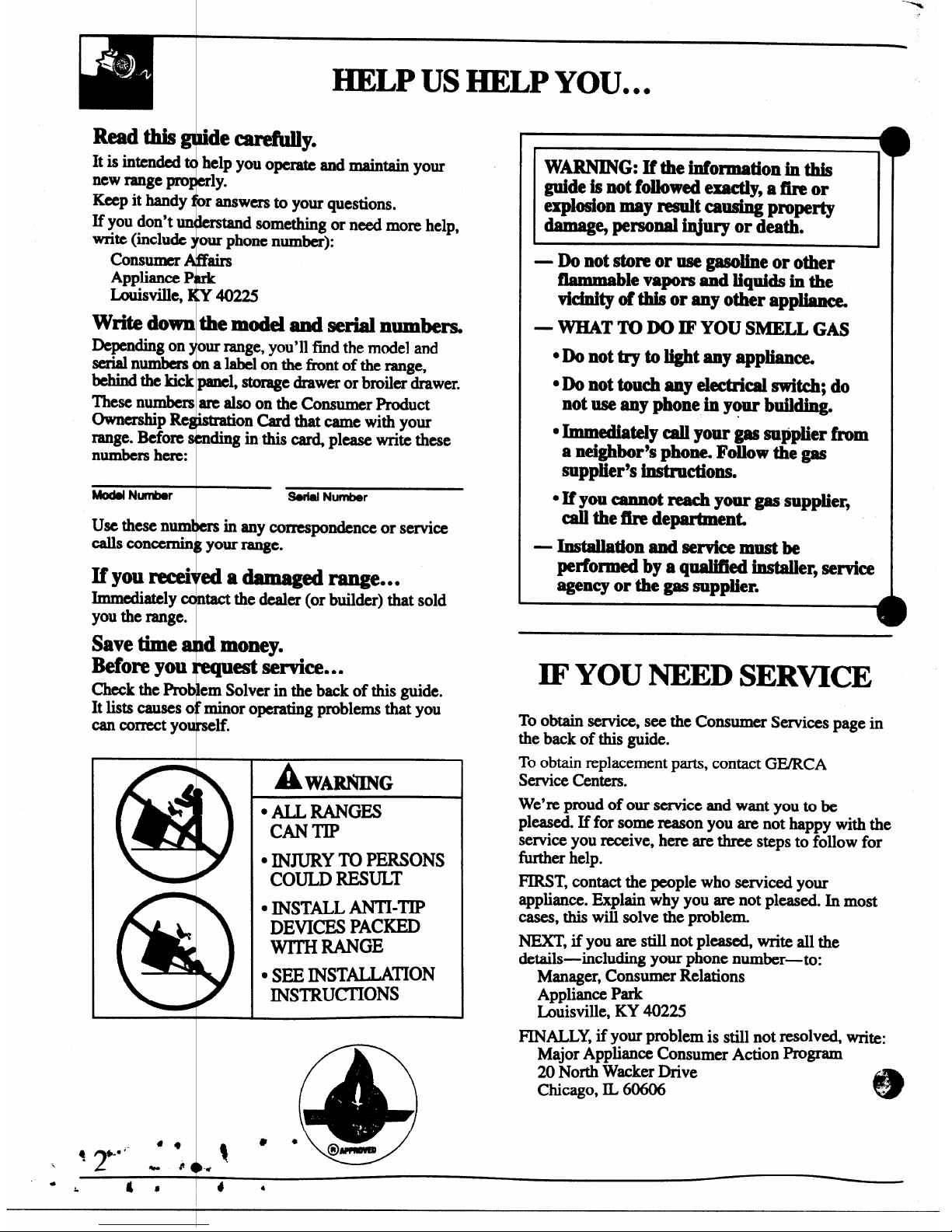
W
&
DEVICES PACKED
WITH lMNGE
● SEE INSTAILA”ON
INSTRU~ONS
b
IF YOU NEED SERWCE
To obtain seMce, see the Consumer Services page in
the back of this guide.
To obtain replacement parts, contact GE/RCA
Service Centers.
We’re proud of our service and want you to be
pleased. If for some reason you are not happy with the
service you receive, here are three steps to follow for
tier help.
FIRST, contact the people who serviced your
appliance. Explain why you are not pleased. In most
cases, this will solve the problem,
NEXT, if you are still not pleased, write all the
details-including
yourphone number-to:
Manager, Consumer Relations
Appliance Park
Louisville, KY 4022S
FINALLY, if
yOUXproblem is still not resolved, wri~:
Major Appliance Consumer Action Program
20 North Wacker Drive
Chicago, IL 60606
e
.
-.
*
Page 3
y
RT~ SAFETY INSTRUCTIONS
Read allMmxtions before using this applianc~
F
“1
~~RTANT S@ETY NOTICE
“TheCalifO
to cause cancer, b“
defects or other reproductive
of
potential expos
to such substances.
Gas appliances
cause minor exposure to
four of thesesub
~ namelybenzene, carbon
substances can be
● “mizedby venting with an
standing pilot
contain mercury. Ifyour
modelhasthesefea~
llres, they must be recycled
iccording to local, s
Me and fderal codes.
dill
i
enYou Get Yurl&qge
ve the installer ow you the location of the
ran= gas cut-off V&e &d how to shut it off
if X&xG&ry.
?
● &ve yourrange ●
talkd and properly
Fded by a q
“ ed installer,in accordance
Withthe Installation Instructions. Any
adjustment
and service should perfbrmed only by qualifixl
gm range installers r service technicians.
i
cord with this appli ce.
therangeou
ofkitchentraffi cpath
andout of drafty I tions to mevent Mot
7
outage (onstan”
pilot rnd=els)and”poor
air circulation.
● Be sure all packing materialsare removedfrom
the range before operating it to prevent fue or
smoke damage should the packing material ignite.
● Be sure your range is correctly adjusted by a
qualMedservice technician or
installer for the
type
of gas (natural or LP) that is to be used.
Yourrange can be converted for use with either
type of gas. Seethe Installation Instructions.
W~ING: Theseadjustments must be made
by a qualified service technician in accordance
with the manufacturer’s instructions and all codes
and requirements of the authority having
jurisdiction. Failureto follow these instructions
could result in serious injury or property damage.
The qualiiled agency performing
this work
assumes responsibility
for the conversion.
● After prolonged use of a range, high floor
temperatures may result and many floor
coverings will not withstand this kind of use.
Never install the range over vinyl tile or linoleum
that cannot withstand such type of use. Never
install it directly over interior kitchen carpeting.
Using Your Range
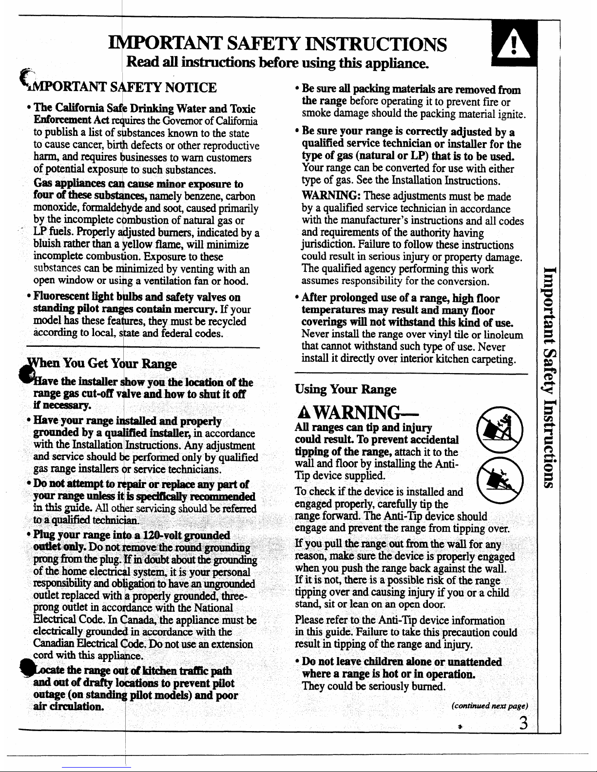
A WARNING-
~ ranges can tip and injury
62)
bl
could resulk To prevent accidental
tipping of the r&ge, attach it to the ~
wall and floor by installing the AntiTIp device supplied.
m
&
To check if the device is installed and
engaged properly, carefilly tip the
range forward. The Anti-’IIpdevice should
engage and prevent the range from tipping over.
If you pull tlmange out *m the wiil for any,
reason, make sure the device is properly engaged
when you push the range back against the wall.
If it is not, there is a possible risk of the range
tipping over and causing injury if you or a child
stan~ sit or lean on an open door.
Please refer to the Anti-Tip device information
in this guide. Failure to take this precaution could
result in tipping of the range and injury.
● DOnot leave children alone or unattended
where a range is hot or in operation.
Theycould be seriously burned.
(continued nextpage)
*
3
7
Page 4
u
1
●
IMl?ORT~ SAFETY INSTRUCTIONS
(continued)
,,
● CAUTION ~MS OF INTEREST TO
cmLmEN
‘sHouLD NoT BE sToRED IN
CABINETS
ABOVE A RANGE OR ON THE
BACKSPLA
SH OF A RANGE-CHILDREN
CLIMBING
ON THE RANGE TO REACH
ITEMS Col
‘
JLD BE SERIOUSLYINJURJ3D.
*Do not *OR
~anyone to climb, stand or hang
on the door,
broiler drawer or cooktop. They
e the range and even tip it over,
cmlsing Sev
.Lettieh
er grates and other surfaces cool
them or leaving them where
chikhen
reachingfor:
tans stored in cabinets over the
co&top. FlaI
nmable material could be ignited if
brought in cc
ntact with flame or hot oven surfaces
cFor your
&, never use your appliance for
waning or heating the room.
•~n~tuseq
rateron grease fires.
Never pick up
aflamingp
an. Turnthecontrols off. Smother a
flaming pan z
m a surface unit by covering the
pan completely with a well-fitting lid, cookie
sheet or flat tray. Use a multi-purpose dry
chemical or foam-type f~
extinguisher.
Flaming grease outside a pan can be put out by
covering it with biking
soda or, if available, by
using a multi
-purpose dry chemical or foam-type
be smothered completely
and turning the oven off
se dry chemical or foa.rn-
s Do notstore Mematdalsinanovqa
orstoragedraweror neara cooktop.
E CO~UST~LE
MATE
, GASOLm OR OTHER
FL
LE VAPORS AND LIQUIDS IN
S OR ANY OTHER
or other fiammable
materials ac
cumulate in or near the range.
● men c~~
Ilgpork, follow the directions exactly
andalwaysa
30
k the meat to an
internal temperature
of at least 17()”F.
T’hk assures that, intheremote
possibilitytha
t trichina maybe present in the meat,
it will be kiii
eciami tie meat wiii be safe to eat.
4-
Surhce Cooking
@
● Always use the LITE position (on electric
ignition models) or the III position (on Wmmg
pilot models) when igniting the top burners and
makesurethe burners have ignited.
● Never leave the surface burners unattended at
highflame settings. Boilovers cause smoking
and greasy spillovers that may catch on f~e.
s Adjust thelop burner flame size so it does not
extend beyond the edge of the cookware.
Excessiveflameis hazardous.
cWe only dry
pot Adders-moist or damp pot
holders on hot surfaces may result in burns fiorn
steam.
● Do not let potholders come near open flames
whenlifting cookware. Do not use a towel or
otherbulky cloth in place of a pot holder.
● To
Mdmize the possibility of burns, ignition
of flammable materials and spillage, turn
cookware handles toward the side or back of the
range without extending over adjacent burners.
● Always turn the surface burners to off before
removing cookware.
@
,
● Carefully watchfoods beiig fried at a high
flame setting.
QNeverblock the vents (air openings) of the
range. Theyprovide the air inlet and outlet that
are necessary for the range to operate properly
with correct combustion. Air openings are located
at the rear of the cooktop, at the top and bottom of
the oven door, and at the bottom of the range
under the broiler drawer.
cDo notusea wokon models with sealed burners
if the
wok has a round metal ring that is placed
over the
burner grate to support the wok. This
ring acts as a heat trap, which may damage the
. burner grate and burner head.
Also, it may cause
the burner to work improperly. This may cause a
carbon monoxide level above that allowed by
current standards, resulting in a health hazard.
s Foods for frying should be as dry as
possible.
Frost on frozen
foods or moisture on fresh foods
can cause hot fat to bubble up and over the sides
of the pan.
. Use the
kast possible amount of fat for effectiv-’.
shallow or deep-fat frying. Filling the pm too ~~
full of fat can cause spillovers when fOOdis added.
● Always heat fat S1OW1YS~d watch M it hea~,
Page 5
c
i
“If a combination foils or fats will be used
in
frying, stirtoge er before heating or as fats
melt slow~y.
. Usea
deep fat the
?
ometerwheneverpossibleto
preventoverheatingfat beyond the smokingpoint.
I
cNevertry to move pan of hotfag especiallya
deepfktfryer.Wai untilthefat is cool.
!
.
uw proper P se
Avoid pans that are
unstable or easily pped. SeIect cookware having
fiat bottoms Iarge e ough to properly contain food
and avoid boilover and spillovers and large
enough to cover b
er grate. This will both save
cleaningtime and p vent hazardousaccumulations
of food, since hea spattering or spillovers left
on range can ignite Use pans with handles that
can be
easily grasp d and remain COOL
1
sWhen using glass o&ware, make sure it is
designed for top-of range cooking.
● Keep ali plastics a~ay from the top burners.
{
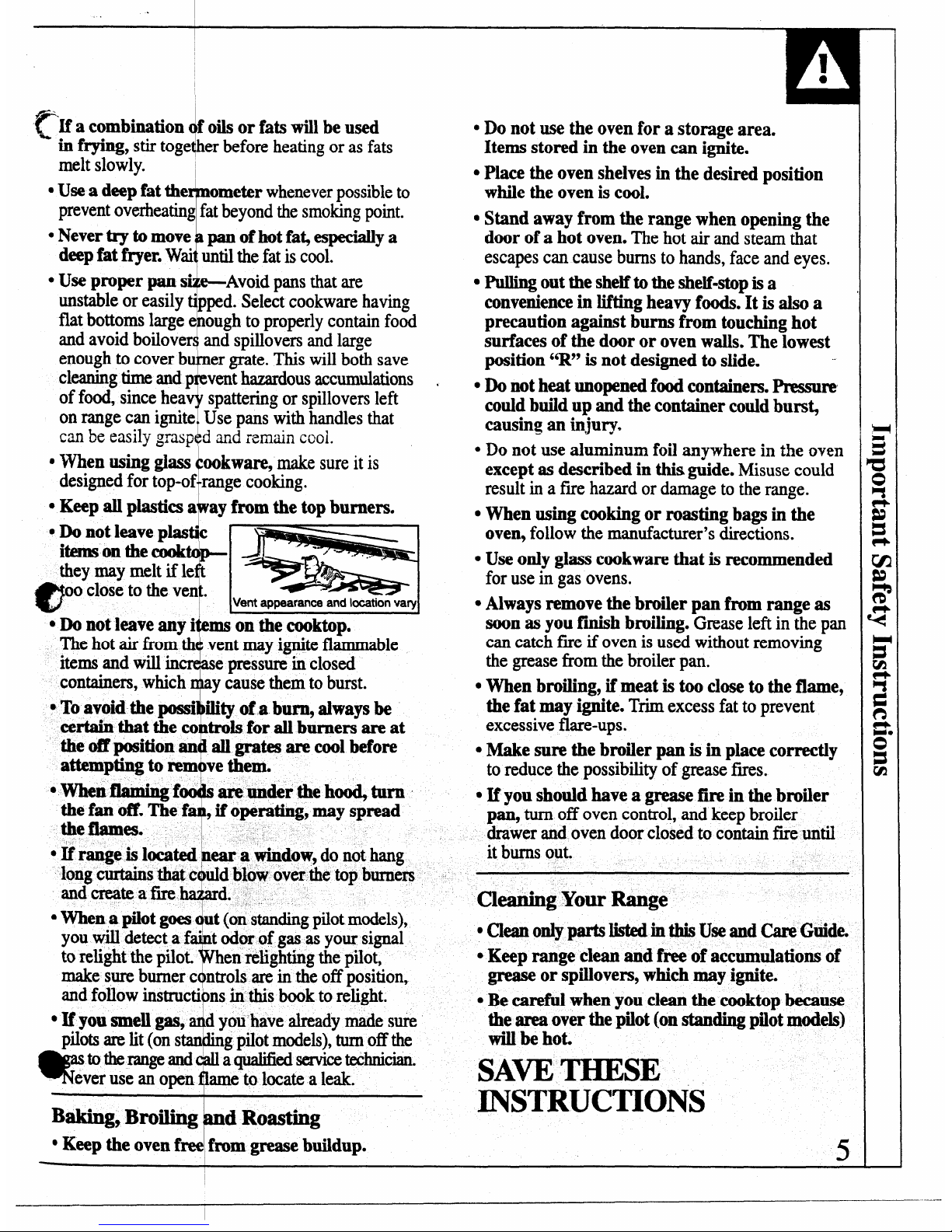
● Do not leave plas c
itemsonthecook ptheymaymelt if le
@
1
oo-closeto the ven.
.
,
e
Vent appearance and location vary
4
GDonot leave any i ms on the cooktop.
Thehot air
horn th vent may ignite flammable
items and Willin
e pressure in closed
containers, which
y cause them to burst.
-4
cToavoid the possi ility of a b- always be
certain that the co trols for all burners are at
the off position an all grates are cool before
attempting to rem ve them.
● -n
“f
are under the ho@ turn ~
thefan off. The f , if operating, may spread
the flames.
4-
—.-
● If range is located ear a yindow, do not hang
long curtains that c &i blow over the top burners
andcreateafire d.
}
cWhen a pilot goes ut (on standingpilot models),
you will detect a f
● t odor of gas as your signal
to relight the pilot.
en relighting the piIot,
make sure burner c ntrols are in the off position,
and follow instructi ns in this book to relight.
!iiiM
● Myou smell gas, d you have already made sure
pilotsare lit (ons
“ g pilot models),turnoff the
w
totherangeand
aqualifiedservicetechnician.
ever use an open
to hxate a leak.
F
Baking, Broiling d Roasting
● Keep the oven free from grease buildup.
T!!
● Do not use the oven for a storage area.
Items stored in
the oven can ignite.
QPlace the oven shelves in the desired position
while the oven is cod.
● Stand away from the range when opening the
door of a hot oven. Thehot air and steam that
escapes can cause bums to hands, face and eyes.
● “
Pullingoutthe shelftotheshelf-stopis a
conveniencein lifting heavy foods. It is also a
precaution against burns from touching hot
surfaces of the door or oven walls. The lowest
position “R” is not designed to slide.
● Do not heat unopenedfoodcontainers.Pmsure
couldbuildup and the container
could burs~
causing an injury.
● Do not use ahunim.m foil anywhere in the owm
except as described in this guide.
Misuse could
result in a f~e hazard or damage to the range.
● When using cooking or roasting bags in the
oven, follow the manufacturer’s directions.
● Use only glass cookware that is recommended
for use in gas ovens.
● Always remove the broiler pan from range as
soon as you finish broiling. Greaseleft
in the pan
can catch fue if oven is used without removing
the grease from the broiler pan.
● When broiling, if meat is too close to the flame,
the fat may ignite. Trimexcess fat to prevent
excessive flare-ups.
● Make sure the broiler pan is in place correctly
to reduce the possibility of grease fins.
. u YOUshodd have
a grease fin in the broiler
p@ turn off oven con~ol, and keep broiler
drawer and oven door closed to contain fmeuntil
.-
it
burns out.
Cl-g
Your Range
●Ckxmonlypartslistedin thisUseand CareGuide.
● Keep range clean and free of accumulations of
grease or spillovers, which may ignite.
● Be careful when you clean the cooktop because
the area over the pilot (onstandingpilot modeh)
will be hot.
SAW THESE
,,
INSTRUCTIONS
I
u
Page 6
6
@-+
II
I
“--P
I
IR-R .
...
-p
@
,,..
+!’--0
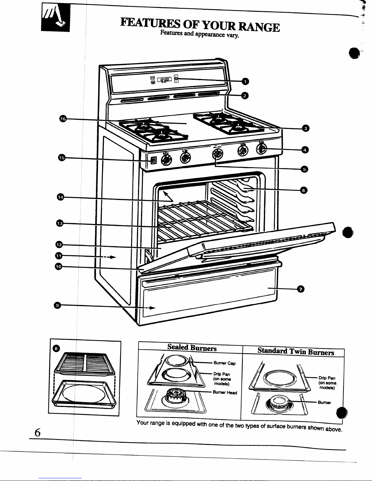
Settled Burnem
Standard Twin Bmem
Burnar~
8
‘:.3 Q (,Z,
DnpPan
Dnp Pan
[~\ ‘u”’’”
{&\ ...r
J
Your range isequippedwithoneofthe wo types of surface burrtem shown above,
I
—_— _
Page 7
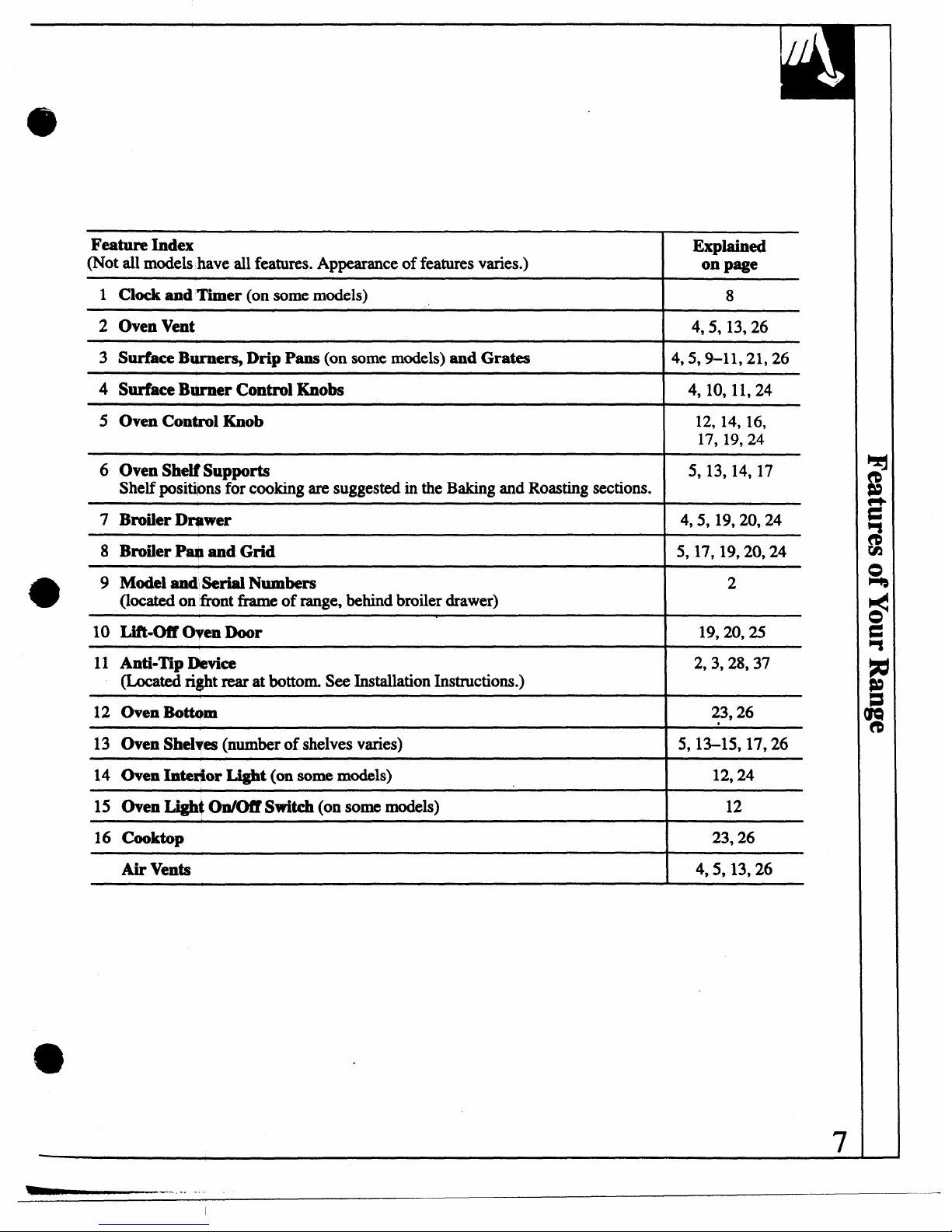
Feature Index
(Not all models have all features. Appearance of features varies.)
1 Clock
andTimer (on some models)
2 Oven Vent
3 Surface Bme~ Drip Pam (on some models) and Grates
4 Surface B@ner Control Knobs
5
OvenControlKnob
6 Oven Shelf Supports
Shelf positions for cooking are suggested in the Baking and Roasting sections.
7 Broiler Dqwer
8 Broiler Pap and Grid
9 Model and Serial Numbers
(located
on fkonttie of range, behind broiler drawer)
10 Lif’k-off men Door
11 Anti-Tip Device
(Located ri$ht rear at bottom. See Installation Instructions.)
12 Oven Bottom
13 Oven Shelves
(number of shelves varies)
14 Oven Intex$or Light (on some models)
15 Oven Ii@@ On/W Switch
(on some models)
16 Cooktop
Air
Vents
Explained
on page
8
4,5, 13,26
4,5,9-11,21,26
4, 10, 11,24
12, 14, 16,
17, 19,24
5, 13,14, 17
4,5, 19,20,24
5,17,19,20,24
2
19,20,25
2,3,28,37
23,26
.
5,13-15,17,26
12,24
12
23,26
4,5,13,26
7
—
Page 8
,,~,
..
.
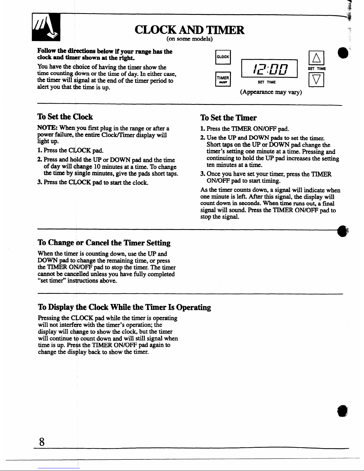
Follow the
Y
ons below if your range has the
.
cbck and
r shown at the right.
Youhave the qhoice of having the timershow the
f
timecounting own or the time of day. In either case,
the timer will ignal at the end of the timer period to
;EzEl[g
SH TIME
alert
you that the time is up.
(Appearance IIMy
VW)
To Set the (10ck
NOTE: When you first plug in the range or after a
powerfailure, he entire Clock/Timer display will
light up.
1. PresstheCI+OCKpad.
2. Press and ~ld the UP or DOWN pad and the time
!
of day will hange 10minutes at a time. To change
the time by ingle minutes, give the pads short taps.
3. Press the C~K pad to start the clock.
To Set the Timer
1. PresstheTIMERON/OFF pad.
2. Use the UP and DOWN pads to set the timer.
Short taps on the UP or DOWN pad change the
timer’s setting one minute at a time. Pressing and
continuing to hold the UP pad increases the setting
ten minutes at a time.
3. Once you have set your timer, press the TXMER
ON/OFF pad to start timing.
As the timer counts dowq a signal will indicate when
one minute is left. After this signal, the display will
count down in seconds.
Whentime runs OUGa final
signal will sound. Press the TIMER ON/OFF pad to
stop the signal.
To Change pr Cancel the Timer Setting
When the time! is counting down, use the UP and
DOWN pad to Ichangethe remainin
g time, or press
the TIMER 01’+VOFFpad to stop the timer. The timer
cannot be canc~lled unless you have fully completed
“set timer” ins@wtions above.
To Display #he Clock While the Timer Is Operating
Pressing the C\OCK pad while the timer is operating
will not interf~e with the timer’s operation; the
display will ch ge to show the clock, but the timer
will continuercount down and will
still signal when
time is up. Pn+s the TIMER ON/OFF pad again to
change the display back to show the timer.
Page 9
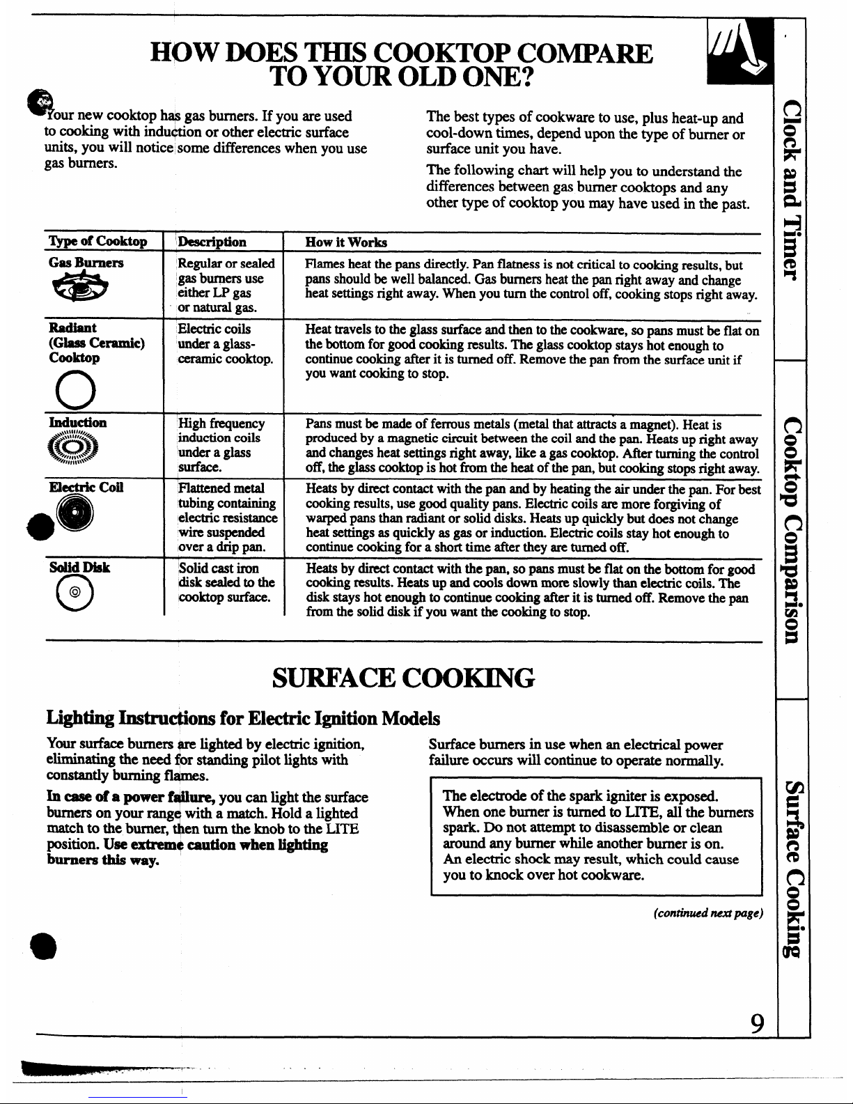
HOW DOES THIS COOKTOP COMPARE
TO YOUR OLD ONE?
Q our new
cooktop hap gas burners. If you are used
The best types of cookware to use, plus heat-up and
to cooking with indu+tion or other electric surface
cool-down times, depend upon the type of burner or
units, you will notice some differences when you use
surface unit you have.
gas burners.
The following chart will help you to understand the
differences between gas burner cooktops and any
other type of cooktop you may have used in the past.
3jrpeof Cooktop
,)lescription How itWorks
Gas Burners
Regularorsealed Flamesheatthe pansdirectly.Pan flatnessis not criticaltocookingresults,but
*
gasburnersuse pans shouldbewellbalanced.Gasburnersheatthepan rightaway andchange
eitherLP gas
heatsettingsrightaway.Whenyou turn thecontroloff,cookingstopsright away.
or natural
gas.
Radiant
Wuabuml$’mtmic)
n
Electriccoils
undera glassCeramicCooktop.
I I
Heattravelsto the glass surfaceand then tothe cookware,so pans mustbe flat on
thebottomfor goodcookingresults.‘I’heglass cooktopstayshot enoughto
continuecookingafterit is turnedoff. Removethe panfrom the surfaceunitif
youwantcookingto stop.
Ektric coil
*e
Highfrequency
inductioncoils
‘imdera glass
surface.
Flattened metal
‘tubingcontaining
electricresistance
wiresuspended
lovera drippan.
Pans
mustbe madeofferrousmetals(metalthatattracti a magnet).Heatis
producedby a magneticcircuitbetweenthecoil andthe pan. Heatsup right away
andchangesheat settingsrightaway,likea gascooktop.Afterturningthe control
off,theglasscooktopis hot fromthe heatofthe pan,but cookingstopsright away.
Heatsby directcontactwiththepan andby heatingtheair underthe pan.For best
cookingresults,use goodqualitypans.Electriccoilsaremoreforgivingof
warpedpansthan radiantor solid disks.Heatsup quicklybut does notchange
heatsettingsasquicklyas gas or induction.Electriccoilsstay hot enoughto
continuecookingfora shorttime aftertheyareturnedoff.
--
SolidDisk
o
Solidcastiron
Heatsbydirectcontactwiththe pan, so pansmustbe flat on the bottomfor good
@
disk sealedto the cookingresults.Heatsup andcools downmoreslowlythanelectriccoils.The
Cooktopsurface.
disk stayshotenoughto continuecookingafterit is turnedoff. Removethepan
fim the soliddiskif youwantthe cookingto stop.
SURFACECOOKING
Lighting Instru@ons for Electric Ignition Models
Ym surface burners @mlighted by electric ignition,
Surface burners in use when an electrical power
eliminating the need $r standing pilot lights with
failure occurs will continue to operate normally.
constantly burning fl@nes.
In ease of a power f#l~
you can light the surface
burners on your rangwitha match. Hold a lighted
a
match to the burner, en turn the knob to the LITE
position. Use extrem+ caution when lighting
burners this way.
The electrode of the spark igniter is exposed.
When one burner is turned to LITE, all the burners
spark. Do not attempt to disassemble or clean
around any burner while another burner is on.
An electric shock may resul~ which could cause
you to knock over hot cookware.
(contbwd next page)
,___
.-
—
Page 10
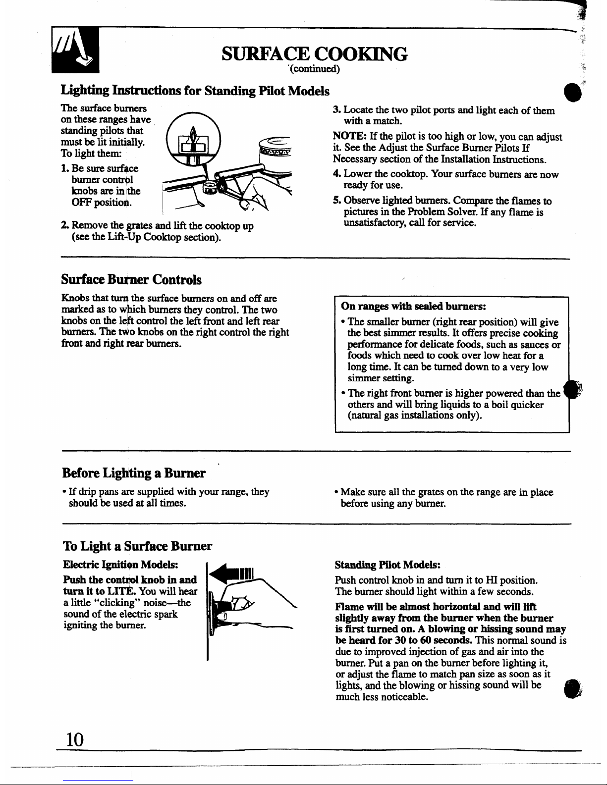
Lighting In@ructions for Standing Pilot Models
e
m
The surface butners
on these ranges have
standingpilots that
must be lit initially.
To light thenx
1. Be sure sud+ce
burner contrpl
knobs are in the
OFF positio~.
2. Remove the-s and lift the cooktop up
(see the Lift+UpCooktop section).
3. Locatethetwopilot ports and light each of them
with a match.
NOTE: If the pilot is too high
or low, you can adjust
it. See the Adjust the Surface Burner Pilots If
Necessary section of the Installation Instructions.
4. Lower the cooktop. Your surface burners are now
ready for use.
5. Observe lighted burners. Compare the flames to
pictures in the Problem Solver. If any flame is
unsatisfactory, call for service.
Surface Burner Controls
Knobs that turIIthe surface burners on and off are
marked as to w~ch burners they control. The two
knobs on the left control the left tint and left rear
burners. The NO knobs on the right control the right
Ihmt and right rear burners.
On ranges with sealed burners:
. The smaller burner (right rear position) will give
the best simmer results. It offers precise cooking
petiormance for delicate foods, such as sauces or
foods which need to cook over low heat for a
long time. It can be turned down to a very low
simmer setting.
A
● The right fi-ont burner is higher powered than the !
others and will bring liquids to a boil quicker
(natural gas installations only).
Before Lighting a Burner
● If drip pans ~ supplied with your range, they
● Make sure all the grates on the range are in place
should be used at all times.
before using any burner.
To Light a Surface Burner
Electric Ignition Models:
Push the control knob in and
turn it to LX~ You will hear
a little “clicking” noise-the
sound of the ehtctric spark
igniting the bu~er.
Standing Pilot Models:
Push control knob in and turn it to HI position.
The burner should light within a few seconds.
Flame will be almost horizontal and will lift
slightly away from the burner when the burner
is first turned on. A blowing or hissing sound may
be heard for 30 to 60 seconds. This normal sound is
due to improved injection of gas and air into the
burner. Put a pan on the burner before lighting it,
or adjust the flame to match pan size as soon as it
lights, and the blowing or hissing sound will be ,
much less noticeable.
a
10
—.—
Page 11
brL@t@aBurner
. After the burner ignites, turn the knob to adjust the
flame size.
. Check to be sure the burner you turned on is the one
YOU want to use.
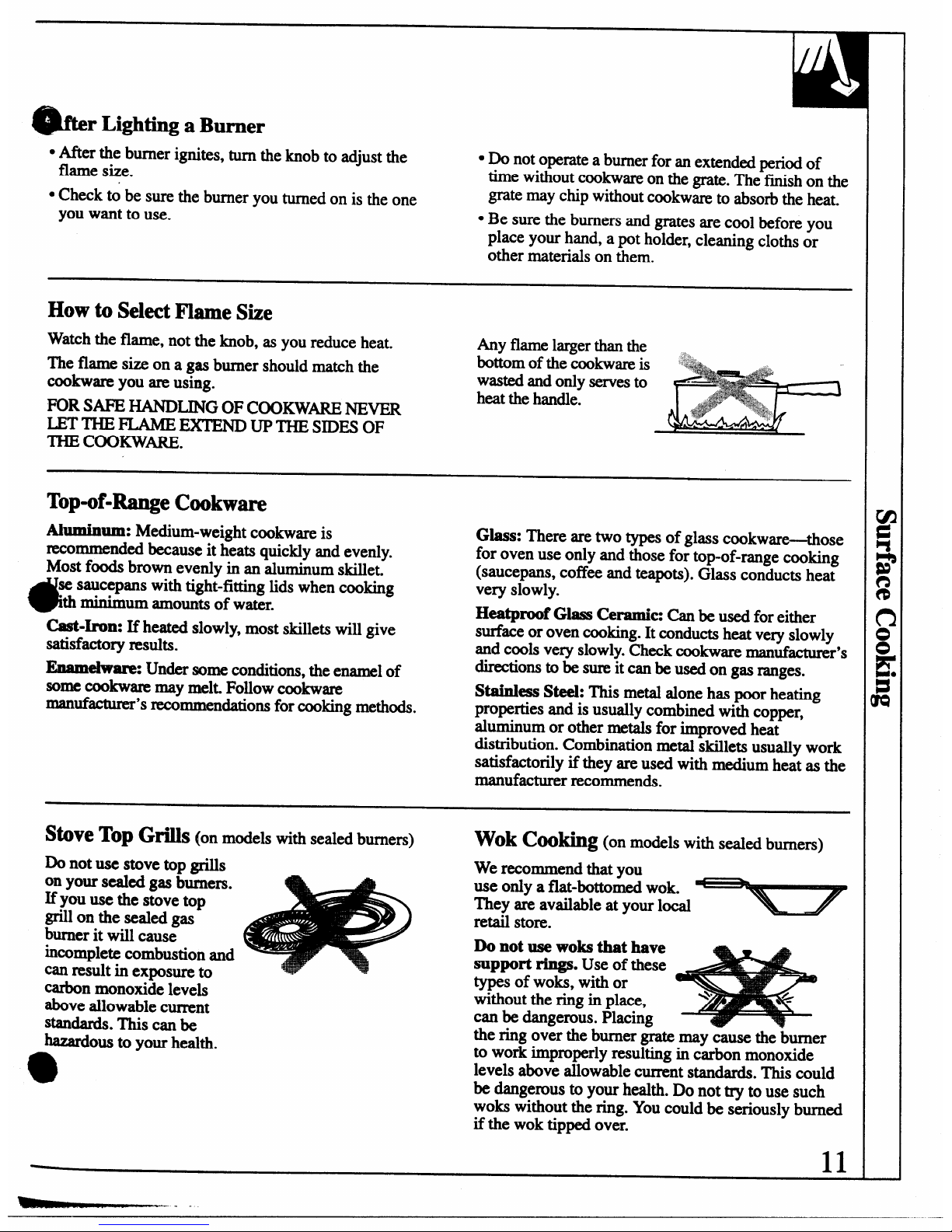
How to Select Flame Size
Watch the flame, not the knob, as you reduce heat.
The flame size on a gas burner should match the
cookware you are using.
FOR SAFE HANDLING OF COOKWARE NEVER
LETTHEFLAME~
UP THE SIDES OF
THE COOKWARE.
“Do not operate a burner for an extended period of
time without cookware on the grate. The finish on the
gratemay
chipwithoutcookwareto absorb the heat.
● Be sure the burners and grates are cool before you
place your hand, apot holder, cleaning cloths or
other materials on them.
Any flame larger than the
bottom of the &okware is
.:..
wasted and only serves to
heat the handle.
Top-of-Range Cookware
Al~um:
Medium-weight cookware is
Glass: There are two types of glass cookware-those
recommended because it heats quickly and evenly.
for oven use only and those for top-of-range cooking
Most foods brown evenly in an aluminum skillet.
*
(saucepans, coffee and teapots). Glass conducts heat
se saucepans with tight-fitting lids when cooking
very slowly.
“thminimum amoumtsof water.
Heatproof Glass Ceramic: Canbe
used for either
Cast-Irom If heated slowly, most skillets will give
surface or oven cooking. It conducts heat very slowly
satisfactory results.
and cools very slowly. Check cookware manufacturer’s
EMmelware: Under some conditions, the enamel of
directions to be sure it can be used on gas ranges.
some COOkwaremay mek Follow
COOkWIUW
Stainless Steel: This metal alone has poor heating
manufacturer’s recommen&tions for cooking methods.
properties and is usually combined with copper,
aluminum or other metals for improved heat
distribution. Combination metal skillets usually work
satisfactorily if they are used with medium heat as the
manufacturer recommends.
Stove Top Gfis (on models with sealed burners)
Wok COohg (on models with seaIed burners)
Do not use stove top grills
We recommend that you
on your sealed gas burners.
use only a flat-bottomed wok.
If you use the stove top
They are available at your load
grill on the sealed gas
retail store.
burner it will cause
Do not use woks that have
incomplete combustion and
support rings. Use of these
can result in exposure to
carbon ~noxide leve~
types of woks, with or
above allowable current
without the ring in place,
can be dangerous. Placing
Stanti. This can be
kardous to your health.
the ring over the burner grate may cause the burner
9
to work improperly resulting in carbon monoxide
levels above allowable cument standards. This could
be dangerous to your health. Do not try to use such
woks without the ring. You could be seriously burned
if the wok tipped over.
11
~.
Page 12
- “---1
Before Using Your Oven
Be sure you understand how to set the controls properly. Practice removing
and replacing the shelves while the oven is cool. Read the information and
tips on the following pages. Keep this guide handy where you can refer to
i~ especially during the first weeks of using your new range.
Lighting Instructions for Electric Ignition Models
The oven burner and broil burner are lighted by
1
electric ignition.
To
lightthe burner, turnthe OVEN CONTROL
knob to the desired temperature. The burner should
light within 30-90 seconds. After the oven reaches the
selected temperature, the oven burner cycle~ff
completely, then on with a full flame-to maintain the
sekcted temperature.
Power Outage
CAUTION: DO NOT MAKE ANY A~ TO
OPERATE THE ELECTRIC IGNITION OVEN
DURING AN ELECTRICAL POWER FmURE.
The oven or broiler cannot be lit during a power
failure. Gas will not flow unless the glow bar is hot.
If the oven is in use when a power failure occurs,
the oven burner shuts off and cannot be re-lit until
power is restored.
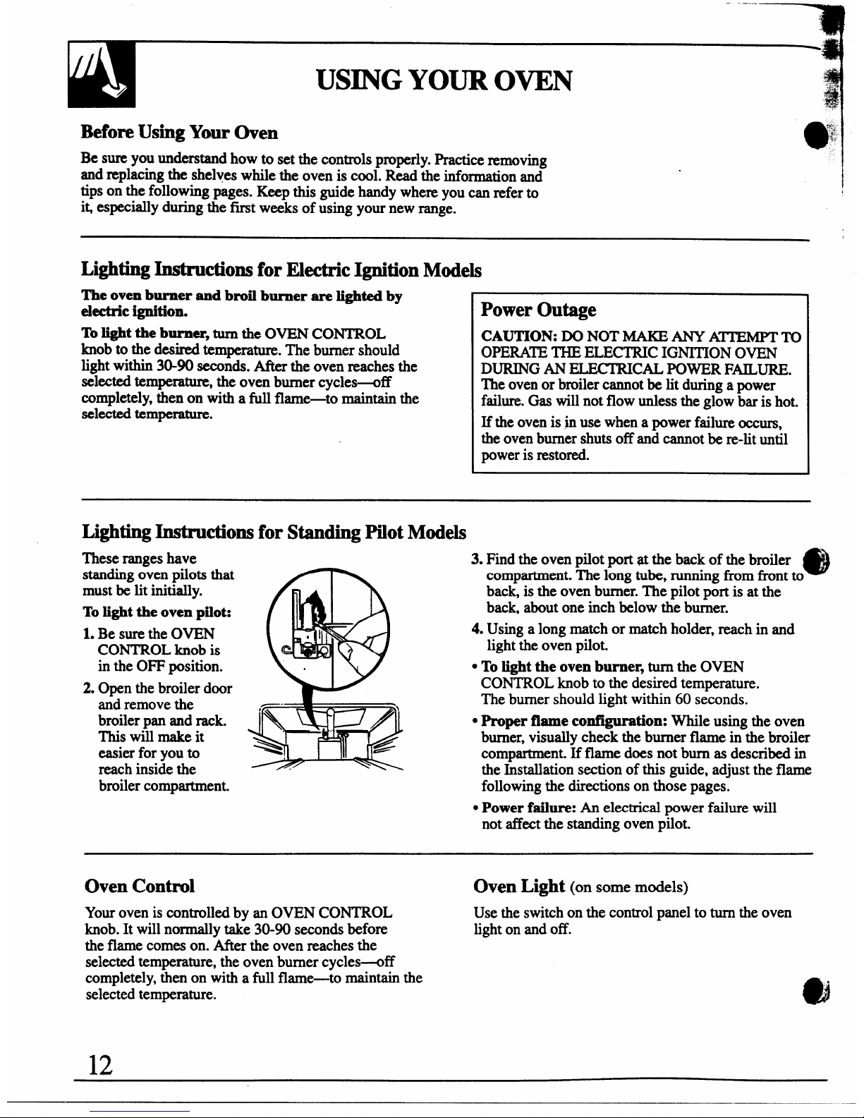
Ligh ●hng Instructions for Standing Pilot Models
Theserangeshave
standing oven pilots that
must be lit initially.
Tolight the oven pilot:
1. Be sure the OVEN
CONTROL knob is
in the OFF position.
2. Open the broiler door
and remove the
broiler pan and rack.
This will make it
easier for you to
reach inside the
broiler compartment.
3. Find the oven pilot port at the back of the broiler
e
compartment. The long tube, running from front to
back, is the oven burner. The pilot port is at the
back, about one inch below the burner.
4. Using a long match or match holder, reach in and
light the oven pilot.
● To light the oven burner, turnthe OVEN
CONTROL knob to the desired temperature.
The burner should light within 60 seconds.
● Proper flame configuration: While using the oven
burner, visually check the burner flame in the broiler
compartment. If flame does not bum as described in
the Installation section of this guide, adjust the flame
following the directions on those pages.
● Power failure: An electrical power failure will
not affect the standing oven pilot.
Oven Control
Oven Light
(on some models)
Your oven is controlled by an OVEN CONTROL
Use the switch on the control panel to turn the oven
knob. It will normally take 30-90 seconds before
light on and off.
the flame comes on. After the oven reaches the
selected temperature, the oven burner cycles-off
completely, then on with a full flame-to maintain the
selected temperature.
12
Page 13
41ib
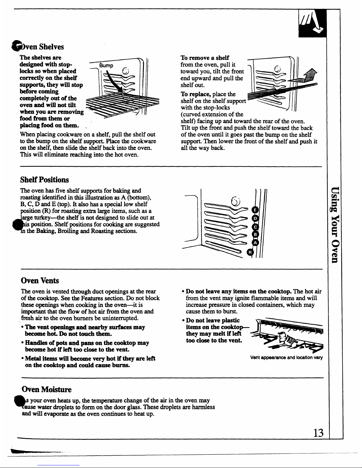
ven Shelves
The shelves are
designed with
StOp-
locks so when placed
correctly on the shelf
supports, they will stop
before coming
completely out of the
oven and will not tilt
when you are removing
food from them or
placing f-on them. .
To remove a shelf
from the oven, pull it
toward you, tilt the front
end upward and pull the
shelf out.
To replace, place the
shelf on the shelf support
with the stop-locks
(tuned extension of the
shelf) facing up and toward the rear of the oven.
‘Illt u~ the front and push the shelf toward the back
When placing cookware on a shelf, pull the shelf out
of th~ oven until it gas past the bump on the shelf
to the bump on the shelf support. Place the cookware
support. Then lower the front of the shelf and push it
on the shelf, then slide the shelf back into the oven.
all the way back.
This will eliminate reaching into the hot oven.
Shelf Positions
Theovenhasfiveshelfsupportsfor baking and
roasting identifiedin this illustration as
A (bottom),
B, C, D and E (top). It also has a special low shelf
position(R) forroastingextralargeiterns,suchas a
d?
e turkey-the
shelf is not designed to slide out at
“sposition. Shelf positions for cooking are suggested
the Baking, Broiling and Roasting sections.
j
Oven Vents
The oven is vented through duct openings at the rear
● Do not leave any items on the cooktop. The hot air
of the cooktop. See the Features section. Do not block
from the vent may ignite flammable items and will
these openings when cooking in the oven—it is
increase pressure in closed containers, which may
important that the flow of hot air fkom the oven and
cause them to burst.
fresh air to the oven burners be uninterrupted.
s Do not leave plastic
● The vent openings and nearby-aces may
itemsonthe cooktop-
becomehot,Donottouchthem.
theymay melt if left
too closeto the vent
. Handlesof pots
and pans on the cooktop may
become hot if left too close to the vent,
● Metal items will become very hot if they are left
Vent appearanceand location vary
on the cooktop and could cause burro
Oven Moisture
Qf
your oven heats up, the temperature change of the air in the oven may
use water droplets to form on the door glass. These droplets are harmless
ad will evaporate as the oven continues to heat up.
13
Page 14
-----qi
~
~
.%:~
.j,
BAKING
J!
@
*!
.
Your oven tempera- is controlled very accurately
If youthinkan adjustmentis necessary,seethe
Adjus
using an oven control system. It is reco~ndd that
the Oven Thermostat section. It gives easy Do It
e
you operatethe ovenfor a number of weeks to
Yourse~hs~ctions on how to adjust the thermostat.
becomefamiliar withyournew oven’s perfo~m.
How to Set Your Range for Btig
To avoid possible burns, place the shelves in the
correct position before you turn the oven on.
1. Close the oven door. ‘Ibrn the OVEN CONTROL
knob to desired tempe-.
2. Check food for doneness at min.imu time on
recipe. Cook longer if necessary.
3. Thrn the OVEN CONTROL knob to OFF and
then remove f~.
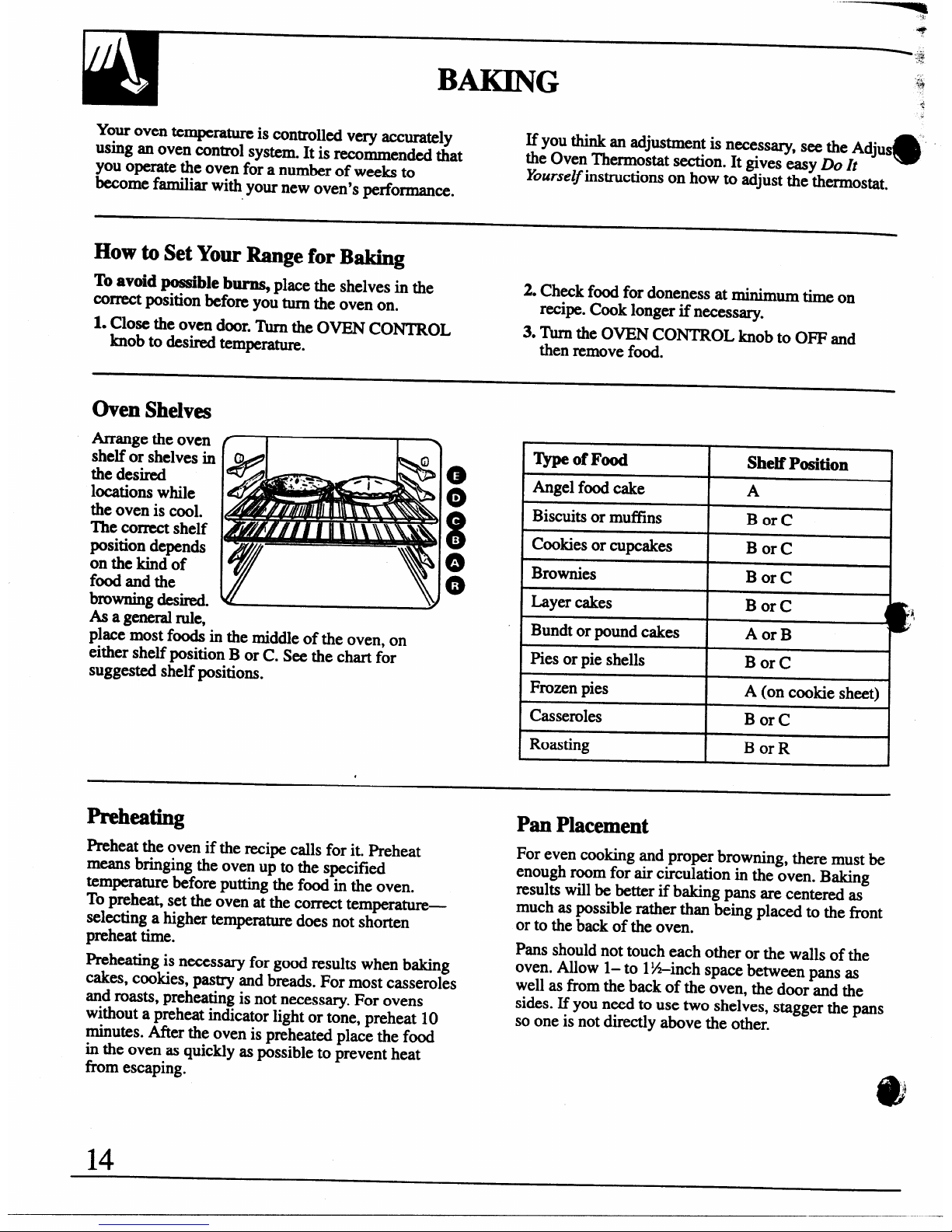
Oven Shelves
Ammge the oven
shelf or shelves in
the desired
locations while
the oven is cool.
The correct shelf
position depends
on the kind of
fd and the
browning desired.
O
.
0
.
As a generalrule,
place most foods in the middle of the oven, on
either shelf position B or C. See the chart for
suggested shelf positions.
,
Preheating
Preheat the oven if the recipe calls for it. Preheat
means bringing the oven up to the specified
temperature before putting the food in the oven.
TOprehea~ set the oven at the correct tempem~—
selecting a higher temperature does not shorten
preheat time.
Preheating is necessary for good results when baking
cakes, cookies, pastry and breads. For most casseroles
and roasts, preheating is not necessary. For ovens
without a preheat indicator light or tone, preheat 10
minutes. After the oven is preheated place the food
in
the oven as quickly as possible to prevent heat
horn escaping.
ljpe of Food
Shelf Position
Angel food cake
A
Biscuits or muffins
Bor C
Cookies or cupcakes
Bor C
Brownies
Bor C
Layer cakes
Bor C
Bundt or pound cakes
Aor B
Pies or pie shells
Bor C
Frozen pies
A (on cookie sheet)
Casseroles
Bor C
Roasting
Bor R
Pan Placement
For even cooking and proper browning, there must be
enough room for air circulation in the oven. Baking
results will be better if baking pans are centered as
much as possible rather than being placed to the tint
or to the back of the oven.
Pans should not touch each other or the walls of the
oven. Allow 1– to 1%-inch space betw~n pans as
well as from the back of the oven, the door and the
sides. If you need to use two shelves, stagger the pans
so one is not directly above the other.
Page 15
@!hkingGuicks
When using prepar
7
baking mixes, follow package recipe or
instructions for best aking results.
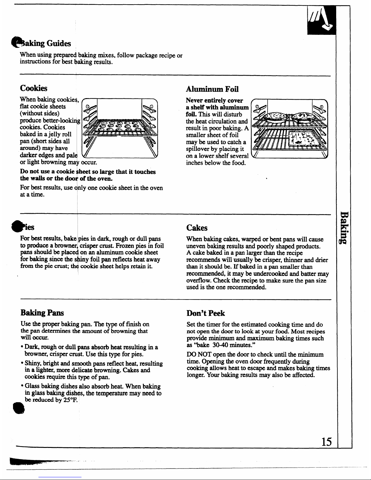
cookies
When baking cookies,
flat cookie sheets
(without sides)
produce better-loo~g
cookies. Cookies
I
baked in ajelly roll
pan (short sides all
around) may have
darker edges and pal
!
~
or light browning ma occur.
Do not use a cookie beet so large that it touches
the walls or the doo of the oven.
For best results, use c@lyone cookie sheet in the oven
at a time. I
Aluminum Fofi
Never entirely cover
a shelf with aluminum
foil. This will disturb
the heat circulation and
result in poor baking. A
smaller sheet of foil
may be used to catch a
spillover by placing it
on a lower shelf several
inches below the food.
●
*
‘es
cakes
+
For best results, bake pies in dark, rough or dull pans
When baking cakes, warped or bent pans will cause
to produce a browner crisper crust. Frozen pies in foil
uneven baking results and poorly shaped products.
paIISshould be pkc
on an aluminum cookie sheet
A cake baked in a pan larger than the recipe
for baking since thes
●
y foil pan reflects heat away
recommends will usually be crisper, thinner and drier
from the pie crust; th cookie sheet helps retain it.
than it should be. If baked in a pan smaller than
recommended, it maybe undercooked and batter may
.
overflow. Check the recipe to make sure the pan size
used is the one recommended.
Baking Pans
Use the proper baking pan. The type of finish on
the pan determines the amount of browning that
will occur.
QDark rough or dull ~ans absorb heat resulting in a
browner, crisper cru$t. Use this type for pies.
● Shiny, bright and smooth pans reflect heat, resulting
in
a lighter, more de~cate browning. Cakes and
cookies require this type of pan.
Don’t Peek
Set the timer for the estimated cooking time and do
not open the door to look at your food. Most recipes
provide minimum and maximum baking times such
as “bake 3040 minutes.”
DO NOT open the door to check until the minimum
time. Opening the oven door fiquently during
cooking allows heat to escape and makes baking times
longer. Your baking results may also be affected.
● Glass baking dishes @o absorb heat. When baking
in glass baking dishqs, the temperature may need to
be l&dUCedby 25”F.
e
15
------. -
Page 16

*
:
~“.
You may feel thjt your new oven cooks diiferentl~
To Adhst the Thermostat:
‘L.
than the one it ~p-heed. We recommend that you -
“
use your new ov
t
-
for a few weeksto becomemore
familiar with i~ f llowing the times given in your
recipes as a guide.
7
If you think yo new oven is too hot or too col~
you ean adjust e thermostat yourself. If you think
it is too ho~ adju t the thermostat to make it cooler.
If you think it is t+mcool, adjust the thermostat to
make it hotter.
We do not reemqmend the use of inexpensive
thermometers, s
lch as
thOW found in grocery StOIW,
to check the temperature setting of your new oven.
These thermometers may vary 2040 degrees.
.-
(app-mce mayvary)
Pull the OVEN CONTROL knob off the range and
look at the back side.
To make adjustment, loosen (approximately one turn),
but do not completely remove, the two screws on the
back of the knob. With the back of the knob facing
you, hold the outer edge of the knob with one hand
and turn the front of the knob with the other hand.
To raise the oven temperature, move the top screw
toward the right. You’ll hear a click for each notch
you move the knob. To lower the temperature, move
the top screw toward the left. Each click will change
the oven temperature approximately 10*F. (Range is
plus or minus 60”F. tim the arrow.)
e
4
We suggest that you make the adjustment one click ‘
from the original setting and check oven performance
before making any additional adjustments.
After the adjustment is made, retighten screws so they
are snug, but be careful not to overtighten. Re-install
knob on range and check performance.
16
--
Page 17

ROASTING
4!!!
“.
oasting is cooking by dry heat. Tender meat or
Roasting is really a baking procedure used for meats.
poultry can be roasted uncovered in your oven.
Therefore the oven controls are set for Baking.
Roasting temperatures, which should be low and
(You may hear a slight clicking sound indicating the
steady, k~ep spattering to a minimum.
oven is working properly.)
The oven has a special
Most meats continue to cook slightly while standing
low shelf (R) position
after being removed horn the oven. Recommended
just above the oven
standing time for roasts is 10 to 20 minutes. This
bottom. Use it when
allows roasts to firm up and makes them easier to
extra cooking space is
cane. Internal temperature will rise about 5° to 10°F.
needed, for example,
If you wish to compensate for temperature rise,
when roasting a large
o
.
remove the roast from the oven when its internal
turkey. The shelf is not .
temperature is 5° to 10°F. less than temperature
designed to slide out at
shown in the Roasting Guide.
this position.
Remember that food will continue to cook in the hot
oven and therefore should be removed when the
desired internal temperature has been reached.
1.Position oven shelf
3. Turn the OVEN CONTROL knob to the desired
at (B) position for
temperature. See the Roasting Guide for
small size roast
temperatures and approximate cooking times.
(3 to 5 lbs.) and at
(R) position for
4. When Roasting is finished, turn the OVEN
larger roasts.
CONTROL knob to OFF and then remove the food
from the oven.
9 . Check the weight of the roast. Place the meat
fat-side-up or the poultry breast-side-upon the
roasting grid in a shallow pan. The melting fat will
baste the meat Sel~t a pan as close to the size of
meat as possible. (Broiler pan with grid is a good
pan for this.)
Dual Shelf Cooking
This allows more than one fd to be cooked at the same time. For example:
While roasting a 20-lb, turkey on shelf position R, a second shelf (if so
q~pped) maybeaddedon positionD so that scalloped potatoes can be
cooked at the same ~. Calculate the total cooking time to enable both
dishes to complete cooking at the same time. Allow 15-20 minutes of
additional cooking time for the potatoes.
Use of Aluminm Foil
Youcan use aluminunI foil to line the broiler pan.
This makes clean-up emier when using the pan for
marinating, cooking with fruits, cooking heavily
- meats or basting food during cooking. Press
w
e foil tightly around the inside of the pan.
(continued next page)
1/
... . . . .
Page 18

.. I
4
.’
ROASTING
,.
~..
,,”.
(continued)
#
:,:.,
‘.,’ ‘
Question8 and Answers
Q. ISit necessamyto checkfor doneness with a
meat therm@neter?
A. Checkingthe finished internal
temperature at the
completion of cooking time is recommended.
Temperatures are shown in Roasting Guide. For
roasts over 8 lbs., check with thermometer at halfhour intervals after half the time has passed.
Q. Why is
myrcbastcrumblingwhen I try to
carve it?
A. Roasts am easiierto slice if allowed to cool 10 to
20 minutes af$erremoving horn oven. Be sure to
cut across the grain of the meat.
Q. Do I need to preheat my oven each time I cook
a roast or poultry?
A. It is not necessary to preheat your oven.
Q. When buying a roa@ are there any special tips
that would help me cook it more evenly?
A. Yes.Buy a roast as even in thickness as possible,
or buy rolled roasts.
Q. Can
I seal the sidesofmyfoil ‘tint” when
roasting a turkey?
A. Sealing the foil will steam the meat. Leaving
it unsealed allows the air to circulate and brown
the meat.
ROASTINGGUIDE
Frozen Roasts
Frozen roasts of @f, pork, lamb, etc., can be started
Make sure poultry is thawed before roasting.
without thawing, but allow 15to 25 minutes per pound
Unthawed poultry often does not cook evenly.
additional time (15 minutes per pound for roasts under
Some commercial frozen poultry can be cooked
5 pounds, more time for larger roasts.)
Meat
Tendercuts;rib,l$gh qualitysirloin
tip,rump or topround*
Lambleg orbone-inshoulder*
Vealshoulder,legor loin*
Pork
lo~ rib or sbouMeP
Ham, Precooked
Poultry
Chickenor Duck
Chickenpieces
‘Ibrkev
Oven
Temperature
325”
325°
325°
325°
325°
325°
350°
325°
Doneness
Rare:
Medium:
WellDone:
Rare:
Medium
WellDone:
WellDone:
WellDone
ToWarm:
WellDone:
WellDone:
WellDone:
successfullywithout thaw-kg. Follow directions
given on package label. -
ApproximateRoastingTime
inMinutesper Pound
3t051bs.
6tQ81bS.
24-35 18-25
35-39
25-31
39-45 31-33
21-25 20-23
25-30 24-28
30-35
28-33
35-45 30-40
35-45 30-40
18-23
IIlilNltESper pound (ilrlyweight;
3t051bs0
Over 5 lbs.
35-40
3&35
35+0
10to 15lbsa
Over 15lbs,
16-22
12-19
Internal
Ikmpemure
‘F.
140°-1500~
1500-160°
1700-185°
140°–1500~
150°-1600
170°–1850
170°-1800
1700-180°
115°-1250
185°-1900
185°-1900
Inthigh:
185°-1900
*Forbonelessrolledroastsover 6 inchesthick,add5 to 10 minutes per pound to times given above.
IThe U.S. Department of Agriculture says “Rare beef is TXWular,but Youshould know that cooking it to only 140°F. means
some food @isoning orga&ms may s&ive.” (Source;%fe Food
Book. Your Kitchen Guide
. USDA Rev~June 1985.)
18
Page 19

BROILING
e
,,
roiling is cooking food by direct heat flom above the Both the oven and broiler compartment doors
fd. Most fish and tender cuts of meat can be broiled.
should be closed during broiling.
Follow these directions to keep spattering and smoking
Turn most foods once during cooking (the exception
to a minimum.
is thin fillets of fish; oil one side, place that side down
Yourrange has a compartment below the oven for on broiler grid and cook without turning until done).
broiling. A specially designed broiler pan and grid
Time foods for about one-half the total cooking time,
allow dripping fat to drain away fkomthe food and
turn food, then continue to cook to preferred doneness.
keeps it away fivm the high heat of the gas flame.
1. Youcan change the distance of the
food from the
heat source by positioning the broiler pan and grid
on one of three shelf positions in the broiler
compartment-A (bottom of broiler compartment),
B (middle) and C (top).
2. Preheating the broiler or oven is not necessary and
can produce poor results.
3. If meat has fat or gristle around the edge, cut
vertical slashes through it about 2 inches apart;
do not cut into the meat. We recommend that you
trim fat to prevent excessive smoking, leaving a
layer about 1/8 inch thick.
4. Arrange the food on the grid and position the
broiler pan on the appropriate shelf in the oven or
broiling compartment. Placing food closer to the
flame increases exterior browning of the food, but
also increases spattering and the possibility of fats
and meat juices igniting.
5.
Close the oven and broiler compartment door.
6. Turn the OVEN CONTROL knob to BROIL.
7. Turn OVEN CONTROL knob to OFF. Remove the
broiler pan from the broiler compartment and serve
food immediately. Leave the pan outside the range
to cool.
e
se of Aluminum Foil
Ym can use aluminum foil to line your broiler pan and
broiier grid. However, you must mold the foil tightly
to the grid and cut slits in it just like the grid.
Without the slits, the foil will prevent fat and meat
juices from draining to the broiler pan. The juices
could become hot enough to catch on fire. If you do
not cut the slits, you are frying, not broiling.
Questions and Answers
Q.When broiling, is it necewary to always use a
Q. Why are my meats not turning out as brc-;n as
grid in the pan?
they should?
A. Yes. Using thegrid
suspends the meat over the
A. Check to see if you are using the recommended
pan. As the meat cooks, the juices fall into the pan,
shelf position. Broil for the longest period of time
thus keeping meat drier. Juices are protected by the
indicated in the Broiling Guide. Turn the food only
grid and stay cooler, thus preventing excessive
once during broiling.
spatter and smoking.
Q. Should I salt the meat before broiling?
A. No. Salt draws out the juices and allows them to
evaporate. Always salt after cooking. Thrn the
@
meat with tongs; piercing the meat with a fork also
allows juices to escape. When broiling poultry or
f~h, brush each side often with butter.
19
.—
—
Page 20

BROILING GUIDE
The oven and broiler compartment doors must be
●Ifdes~mwinate
meatsorchickenbefore broiling.
closed during broiling.
q
Orbrush with barbecue sauce last 5 to 10minutes only.
● Always use the broiler pan and grid that comes with
●
W
yourrange.It is designed to
minimize smoking and
d
spattering by trapping the juices in the shielded lower
so
henarranging the food on the pan, do not let fatty ~
geshang over the sides because dripping fat could
1the oven.
i
part of the pan.
cThe broiler compartment does not need to be
● For steaks and chops, slash the fat evenly around the
preheated. How&er, for very thin foods, or to
outsi& edges of the meat. To slash, cut crosswise
through the outer fat surfacejust to the edge of the
meat Use tongs to turn the meat over to prevent
piercing the meat and losing juices.
bcrease browning, preheat E desired.
● Frozen steaks can be broiled by positioning the shelf
at the next lowest shelf position and increasing the
cooking time given in this guide 1X times per side.
Quantity and/or shelf
Food
‘II&knew
Position
Bacon
l/2-lb.
B
(about 8thinslices)
Ground Beef
l-lb. (4 patties)
A
Well Done 1/2 to
3/4-inchthick
Beef steaks
l-inch thick B
Medium (1-1%lbs.)
B
WellDone A
I%-inchthick
B, C
Medium (2-2%lbs.) B
WellDone A
Chicken
1whole
A
(2to 2%-lbs.),
splitlengthwise
Bakery
Products
Bread (T’) or
2A slices
c
Toaster Pastries
1pkg. (2)
English Muffins 2-split
c
Lobster Tails 2-4 A
(6 to 8-oz. each) ‘
Fish
l-lb.fillets 1/4 to B, C
l/2-inch thick
Ham slices
l-inch thick
B
Precooked
Pork Chops
2(1/2-inch)
B
Weil Done
2 (l-inch thick), B
about 1 lb.
Lamb Chops
Medium
2 (l-inch),
B
WellDone about 10-12 oz.
B
Medium
2(1!4-inch),
B
WellDone
about1 lb. B
Comments
Arrangein singlelayer.
10-11 4-5
Space evenly. Up to 8 patties take
about same time.
1
9
12
13
7
5-6
8-9
Steaksless than l-inch cookthrough
beforebrowning.
Pan fryingis recommended
Slashfat.
10
12-15
25
6-7
10-12
16-18
Reduce times about 5 to 10 minutes
per side for cut-up chicken. Brush each
side with melted butter. Broil with skinsidedown f-.
30-35 I 25-30
2-3
1/2-1
3-5
Space evenly. Place English mufths
cut-side-up and brush with butter,
if desired.
Do not
turn over.
Cut through back of shell, spread
open. Brush with melted butter
before broiling and &half of
broilim? time.
5 5
Handle and turn very carefully. Brush
with lemon butter before and during
cooking, if desired. Preheat broiler to
increase browning.
Increase times 5 to 10 minutes per side
for 1%-inchthick or home cured.
8
I
8
10
13
4-5
9-12
Slash fat.
8
10
10
17
4-7
10
4-6
12-14
Slashfat.
i)
1:
If desired, split sausages in half
lengthwise; cut into 5- to 6-inch picccs.
Wiene~
l-lb. pkg. (10)
B, C
similar precooked
sausages,bratwurst
6
1-2
20
Page 21

CAREAND CLEANING
?%
,f-
L* *
per care and cleaning are important so your range
BE SURE ELECTRICAL POWER IS
‘will
give you efllcient and satisfactory service. Follow
DISCONNECTED BEFORE CLEANING ANY
these directions carefully in caring for it to help assure
PART OF YOUR RANGE.
safe and proper maintenance.
I
CAUTION: DO NOT OPERATE THE BURNER WITHOUT ALL BURNER PARTS AND DRIP PANS
(IF SO EQUIPPED) IN PLACE.
I
Sdd Burner Assemblies (on some models)
~G~te
Burner Cap
Drip Pan
(on some models)
L!!!!iF::::d
‘lhrn all controlsOFF beforeremovingthe
burnerpartsanddrip pans (if so equipped).
e
e burner- ca~ burnerheadsand drip
(ifso equipped)canbe liftedoff, makingthem
easy to clean.
The electrode of
the
spark igniter is
exposed when the
burner head is
[@+/Ebftrode
removed.Whenone
burner is turned to LITE, all the burners spark.
Do not attempt to disassemble or clean around
any burner while another burner is on. An electric
shock may resul~ which could cause you to knock
over hot cookware.
Burner Heads (on sealed burners OnIY)
For proper ignitio~ make sure the small hole in
the section that fits over the electrode is kept open. A
sewing needle or wire twist-tie works well to unclog it.
The slits in the burner heads of your range
must be kept clean at all times for an even,
unhampered flame.
You should clean the surfaceburnersroutinely,
especially afterbadspillovers, which could clog
these openings.
To remove burned-on food, soak theburnerheads
in a solution of mild liquid detergentand hot water
for 20-30 minutes. For more stubborn stains, use a
toothbrush.
Before
puttingtheburnerheadback, shakeout
excess water and then dry it thoroughly by setting
it in a warm oven for 30 minutes.
Replace the burnercaps. Make surethat
caps are
replacedon the correct size burner.Thereis one
small, 2 medium andone largecap.
Burner (bps (on sealed burners only)
Liftoff when cool. W@hburner caps
in h@ soapy water and rinse with
clean water. You may scour with a
plastic scouring pad to remove
burned-on fd particles.
Dry
them in a warm oven or with a
cloth-don’t reassemble them wet.
e
eplace the burner caps.
‘Make sure that caps are replaced on
the correct size burner. Them is one
small, 2 mediumandone huge cap.
medium
a %s”’”
‘e”uml@@+’a”e
I
1
.
“
“
Front of Range
(continued next page)
21
————.— ---
Page 22

T
:
.1
CAREAND CLEANING
;7
.,
(continued)
4
i= ~
&
CAUTION: DO NOT OPERATE THE BURNER WITHOUT ALL BURNER PARTS AND DRIP P~S
~
(IF SO EQUIPPED) IN PLACE.
/
I
S*d~d h Burners (on some models)
Grate
-~=-s)
Surface Burner
On models with standard twin burners, the cooktop
lifts up for easy access.
‘Ihrnall
controlsOFF beforeremoving burner
p- and drip pm (if so Whipped).
The burner grates and drip pans (ii so equipped)
can be lifted off, making them easy to clean.
The holes in the surface
burnersof your range
must be kept clean at all
times for proper ignition
and an even,
unhamperedflame.
m
e
9.
&
Clean these
holes
.
%2&
on each
burner.
You should clean the surface burners routinely, I
especially after bad spillovem, which could clog
these holes. W@eoff surfaceburners.If heavy
spilloveroccurs, remove the surfaceburnersfrom
I
range.Burnerslift out for cleaning. Lift up the
cooktopandthen lifi out the surfaceburners.
To remove
burned-onf- soakthesurface burner
in a solution of mild liquid detergent and hot water.
Soak the surface burner for 20 to 30 minutes. For
more stubborn stains, use a cleanser like Soft Scrube
brand or Bon Ar# brand. Rinse well to remove any
traces of the cleanser that might clog the surface
burner openings. Do not use steel wool because it
will clog the surfaceburneropenings and scratchthe
swface burners.If the holes become clogged, clean
them with a sewing needle or twist tie.
Before putting the surface burner back, shake out
excess water and then dry it thoroughlyby setting it in
*
a warm oven for 30 minutes. Then place it back in th
range, making sure it is properly seated and level.
~fip
Pm (on some models)
Remove the grates and
\
#
lift out the drip pans.
--~
Drippans canbe cleaned
in a dishwasheror by
hand.
~Q\
.
To get rid of burned-on food, place them in a
covered container (or plastic bag) with 1/4 cup
ammonia to loosen
the soil. Then scrub with a
soap-filled scouring pad if necessary.
22
—-. ... .....
—
Page 23

Lift out when cool. Grates should be washed regularly
and, of course, after spillovers. Wash them in hot,
soapy water and nns~ with clean water. After
cleaning, dry them thoroughly by putting them in a
warm oven for a few tiutes. Don’t put the grates
back on the range wl@e they are wet. When replacing
the grates, be sure thqy’re positioned securely over the
burners.
To
preventrustingon castirongrates,apply a light
coating of cooking oil on the bottom of the grates.
To
get rid of burned~onfd, place the grates in a
coveti container (or plastic bag) with 1/4 cup
ammonia to loosen the soil. Then scrub with a soapfilled scouring pad if necessary.
Although they’re durable, the grates will gradually
lose their shine, regardless of the best care you can
give them. This is due to their continual exposure to
high temperatures.
Do not operate a burner for an extended period of
time without cookware on the grate. The finish on the
grate may chip without cookware to absorb the heat.
(hoktop Surface
To avoid damagingtiheporcelainenamelsurface
ofthe cooktopandto prevent
it fiwm becoming
d~
cleanup spills right away. Foods with a lot of
acid (tomatoes, sauerkraut fruitjuices, etc.) or foods
with high sugar content could cause a dull spot if
&
owed to set.
t
en the surface has cooled, wash and rinse. For
other spills such as fat smatterings,etc., wash with
soap and water once me surface has cooled. Then
rinse and polish with a dry cloth.
Be carefid when you dean the cooktop because
the area over the pilot will be hot (on models with
standing pilots).
Do not store flammable materials in an oven or
near the cooktop. Do not store or use combustible
materials, gasoline or other flammable vapors and
liquids in the vicinity of this or any other appliance.
Oven Bottom
The oven bottom has a porcelain enamel finish.
To make cleaning caster,protecttheoven bottom
fbm excessive spillovem by placing a cookie sheet
on the shelf below the shelf you are cooking on. You
can use aluminum foil if you do not cover the whole
shelf. This is particu~ly important when baking a
fruit pie or other foods with a high acid content. Hot
fruit fillings or other fbods that are highly acidic
(such as milk, tomat@s or sauerkraut, and sauces with
vinegar or lemon juice) may cause pitting and damage
to the porcelain en-l surface and should be wiped
s
p imiidiately.
If a spillover does occur on the oven bottom,
allow the oven to cool first.
Frequent wipings with mild soap and water
(particularly after cooking meat) will prolong the time
between major cleanings. Rinse thoroughly. Soap left
on the oven bottom can cause stains.
For heavy soil, use an abrasive cleaner or a soapfilled scouring pad. A commercialoven cleaner may
also be used, following the package directions.
(continued next page)
—
Page 24

‘---7
-’a
CARE - CLEANING
a
.. >
..
.
.,
(continued)
Oven Light Ihib (on some models)
The light bulb is located in the upper left comer
of the oven. Before replacing your oven light bulb,
disconnect the electrical power to the range at the
main fhse or circuit breaker panel or unplug the
range tim the ekctrical outlet. Let the bulb cool
completely before removing it. Replace the bulb with
a 40 watt appliance bulb only. Do not touch a hot bulb
with a damp cloth as the bulb will break
.
Control Panel and Knobs
It’s a good idea to wipe the control panel after each The control knobs may ~
use of the oven. clean with mild soap and water or be removed for easier
vinegar and water, rinse with clean water and polish cleaning.
To remove
dry with a sofi cloth.
knob, pull it straight
Do not use abrasive cleansers, strong liquid cleaners,
off the stem.
plastic scouring pads or oven cleaners on the control Wash the knobs in soap
panel-they will damage the finish. A 50/50 solution and water or a vinegar and
of vinegar and hot waterworks well.
hot water solution but do
not soak.
Metal parts can be cleaned with soap and water.
Do not use steel wool, abrasives, ammonia, acids
or commercial oven cleaners. Dry with a soft cloth.
a
,1
Removable IllroilerDrawer (on some models)
To remove:
1.
When the broiler is cool, remove the grid and pan.
2. Pull the bmile~drawer out until it stops, then push
it back in about one inch.
3. Graspthe handle, liftand pullbroiler drawer out.
~lean the broilerdrawerwith hot soapy water.
To replace:
Hold the broiler drawer in the raised position as you
slide it partway into the range. Then lower the drawer
and push it completely closed.
Broiler Pan and Grid
After broiling, remove the broiler pan. Remove the
Both the broiler pan
grid tim the pan. Carefully pour out grease from the
and grid can also be
pan into a proper container. Wash and rinse the broiler
cleaned in the dishwasher.
pan and grid in hot water with a soap-filled or plastic
Do not store a soiled
scouring pad.
broiler pan and grid
I
1
If food has burned o%sprinkle the rack with detergent
I
anywhere in the range. ;
while hot and cover with wet paper towels or a
I
dishcloth. Soal@g the pan will remove burned-on foods.
I
24
‘&
————..—.-..——
-—
Page 25

l!?
.
Lift-Off Oven Door
The oven door is removable but it is heavy. You may TO CLEAN THE DOOR:
need help removing and replacing the door. (Do not immerse door in water.)
To remove the door. M
Inside of dom
open it a few inches to
Pvllll
I
the specialstop
positionthatwill hold
thedooropen.
Grasp
firmly
oneach side
and lift the door
straight Upand Off
the hinges.
NOTE: Be careful
not to place hands
between the hinge
and the oven door
frame as the hinge
could snap back and
pinch fingers.
Toreplace the dooq, make sure the hinges are in the
special stop position. Position the slots in the bottom
of the door squarely over the hinges. Then lower the
door slowly and eve@y over both hinges at the same
time. If hinges snap back against the oven frame, pull
. Allow to cool before cleaning. For light soil, wipe
frequently with mild soap and water ~especially-after
cooking meat). This will prolong the time between
major cleaning. Rinse thoroughly.
NOTE: Soap left on the oven door causes
additional stains when the oven is reheated.
. For heavy soil, choose an oven cleaner and follow
label instructions. Rinse well.
Outside of door:
QUse soap and water to thoroughly clean the top,
sides and tint of the oven door. Rinse well.
You may also use a glass cleaner to clean the glass
on the outside of the door. ,
. Spillage of marinades, hit juices, tomato sauces
and basting materials containing acids may cause
discoloration and should be wiped up immediately.
When surface is cool, clean and rinse.
● Do not use oven cleaners, cleansing powders or
harsh abrasives on the outside of the door.
Porcelain Oven Interior
WM proper care, thpporcelain enamel interior will
retain its attractive finish for many years.
Soap and water will normally do the job. Heavy
spattering or spillov$xs may require cleaning with a
mild abrasive cle~er. Soapy, wet pads may also be
used Do not allow @od spills with a high sugar or
acid content (such @ milk, tomatoes, sauerkraut, iiuit
juices or pie ffig) to remain on the surface. They
may cause dull spot$ even after cleaning.
Household ammoni~ may make the cleaning job
easier. Place 1/2 cup ammonia in a shallow glass pan
ad leave in a cold dven overnight. The ammonia
fumes will help loo~n the burned-on grease and food.
When necessary, yOI,I may use a commercial oven
cleaner. Follow the @ckage directions.
Cautionsaboutusingspray-onovencleaners:
● Be careful where the oven cleaner is sprayed.
● Do not spray oven cleaner on the electrical controls
and switches (on some models) because it could
cause a short circuit and result in sparking or fire.
● Do not mow a fi~ from the cle~er to m~ on
the temperature sensing bulb-it could cause the
oven to heat improperly. (The bulb is located at the
rear of the oven.) Carefully wipe the bulb clean after
each oven cleaning, being careful not to move the
bulb as a change in its position could affect how the
oven bakes.
. Do not spray any oven cleaner on the outside oven
door, handles or any exterior surface of the oven,
cabinet or painted surfaces. The cleaner can damage
these surfaces.
(continued next page)
25
—
Page 26

Oven Shelves
Clean the shelves with an abrasive cleanser or
steel wml. M&r @xming, rinse the shelves with
clean water anddry with a clean cloth.
~fi-llp
C()()k~p (on models with standard twin burners)
Clean the area under the cooktop often. Built-up soil,
especially grease, may catch on fire.
To make cleaning
easier, the cooktop may be
lifted up.
To raise the cooktop:
1.Be sure the b~ers are turned off.
2. Remove the grates.
3. Graspthe two tint burnerwells and lift up.
Some
modelshave dual supportrodsthat willhold the
cooktopup whileyou clean underneathit.
AftercleaningWalertheeooktop
with hot,
soapy water and a clean cloth, lower the cooktop.
Be careful not to pinch your fingers. Lower the
cooktopgentlyto avoid blowingoutpilot flames (on
standingpilotmodels).
Oven Air Vents
Never block the vents (air openings) of the range.
They providethe airinlet and outlet that are
necessary for the range to operate properly with
correct combustion. Air openings are located at the
rear of the cooktop, at the top and bottom of the oven
door, and at the bottom of the range, under the kick
panel, storage drawer or broiler drawer (depending on
the model).
Vent appearance and location vary
26
-. —
—
Page 27

‘ FOR YOUR SMETY
If
you smell gaw
1. Open windows.
2.
Don’t touch electrical switches.
3. Extin@u
‘sh
anyopen flame.
4.
Immediately cd yourgas supplier.
FOR YOUR SAFETY
Do not store or use combustible
materials, @soline or other flammable
vapors and Hqtids in the vicinity of this
or any other appliance.
BEFORE YOU BE6W
Read these instructions completely and
IMPORT- Savethese instructions
for the local electrical inspector% use.
)
INSI’..I& Leave these instructions
with the appliance after installation is
completed.
CONSUMER Keep
thiS Use and&m
Guide and the Ik@aktion Instructions
for fkture use.
I
wARlm16
Improper insta@on, adjustment
alteration, service or maintenance can
cause injury or property damage. Refer
to this @de. For assistance or additional
information, ~sult a qualikl installer,
service agency, manufkturer (dealer) or
the gas supplier.
I CAUTION
4
Do not attempt to operatethe oven
of this _ da a
power fhilure
&
(Electric Ignition models only).
IMPORTANT
Remove all packing material and
literature from oven before connecting
gas and electrical supply to range.
DIMENSIONS AND CLEARANCES
Provide adequate clearances between the range
and adjacent combustible surfaces.
Depth with door closed
I
Saa chati
balow for
height
I
7
Depth with
\
\
door open:
\
\+
##~
46%”
\
\
\
d“””
<d~~
/
Range Height
4(y LGB116
44”
LGB126
~~” LGB146
LGB156
18”
(cmtinned
nt@@w)
27
—..
.———-.. — -
Page 28

9MPORTAHT SAFETY 9HSTRUCTIOUS
Installation
of this- must conform with
local codes, atrin the absence of local codes,
with the National Fuel Gas Code, ANSI
~~,1, _ ‘ire- b qN~~%?
must conform with the curren
Installation Code, CAN/CGA-B149.l or the
curnmt Prqmne In8talMon Code, CAN/CGAB149.2, and with local codes where applicabl~
This rangehas been design-cetied by the
AmericanGas&ociation accordingtoANSI221.1,
latest edition axmdCanadian Gas Association
according to CAN/CGA-l.l latest edition. As with
my
wpliance using gas and generating hea$
there are cerh@ safetyprecautions you should
follow.Youwillfind these precautions in the
Important Safety Instructions in the front ofthis
guide. Read them care$idly
● Have your range installed by a qualified
installer or service technician.
● Yourrange ust be electrically grounded in
%
accordance wi local codes or,in the absence of
local codes, in accordance with the National
Electrical Code (ANSI/NFPA70, latest edition).
In Canad~ elec@=icalgrounding must be in
aamdance wia the current CSAC22.1Canadian
Electrical Code Part 1and/or local codes. See
Electrical Com@ions in this section.
● Before ins@ng your range on linoleum or
any other synthetic floor covering, make sure
the floor covering can withstand 180°11without
shrinking, warping or discoloring. Do not install
the range over carpeting unless ~sheet of 1/4”
thick plywoodor similar insulator is placed
between the range and carpeting.
● Make sure the wall coverings around the
range can with@andheat generated by the
range up to 200”I?
● Avoidplacing cabinets above the range. To
reduce the h-d caused by reaching over the
open flames ofoperating burners, install a
ventilation hood over the range that projects
forwardatleast 5“beyond the front ofthe cabinets.
● The ventilating hood must be constructed of
sheet metal not less than
0.0122” thick. Install
above tie cooktop with a clearance of not less
than 1/4” between the hood and the underside
of the combustible material or metal cabinet The
hood must beat least as wide as the appliance and
centered over the appliance. Clearance between
the cooking surf&ceand tie ventilation hood surke
MUS1’_BEU3S!3’111AN 241NCHES.
EXCEPTION: Installation ofa listed microwave
oven or coo-appliance over the cooktop shall
conform to the installation instructions packed
with that appliance.
--
28
s If cabinets are placed above the range, allow a
minimum clearance of30”between the cooking
surface and the bottom of unprotected cabinets.
. E a 30”clearance between cooking sudiwe and
overhead combustible material or metal cabinets
cannot be maintained, protect the underside of
the cabinets above the cooktop with not less
than 1/4” insulating millboard covered with
sheet metal not less than 0.0122”thick.
. Clearance between tie cooking surfkce and
protected cabinets MUSI’
NEVER BE IESS
‘IIMN 24
INCHES. ‘I%evertical distance from
the plane ofthe cooking surf&ceto the bottom
ofadjacent overhead cabinets extending closer
than 1“to the plane of the range sides must not
be less than 18”.(See Dimensions and Clearances
illustration in this section.)
● Caution: Items of interest to chfldren should
not be stored in cabinets above a range or on the
backsplash of a rang=hildren climbing on the
range to reach items could be seriously injured.
WARBUH6
A
Q!?!!!)
4
M ranges can tip and injury ‘
b
could result.
To prevent
accidentaltippingofthe range,
attach an approved Anti-’Np
device to the wall. (See
hstdimz the Anti-~ID Device
in this s&tion.) To check if
the device is installed and
engaged properly, carefully
tip the range forward. The
AntiTip device should engage
and prevent the range fi-om
tipping over.
Ifyou
pull the range out fi=om
the wall for any reason, m&e sure the-Anti-Tip
device is engaged when you push the range back
against the wall.
c Foryour safety,neveruse your range forwarming
or heating the room. Your oven and cooktop are
not designed to heat your kitchen. Top burners
should not be operated without cookware on the
grate. Such abuse could result in fire and damage
to your range and willvoid your warranty.
s Do not store or use combustible materials,
gasoline or other flammable vapors and liquids
in the vicinity of this or any other appliance.
Explosions or fires could result
● Do not use oven for a storage area. Items
stored in the oven can ignite.
● Do not let cooking grease or other flammable
materials accumulate in or near the range.
—
——
_-..—.—
Page 29

GENERAL
. See
Dimensions and Clearances in this section
for all rough-in and spacing dimensions. These
dimensionsmust be met forsafeuse ofyourrange.
The locationofthe electricaloutlet and pipe opening
(see Gas Pipe and Electric Outlet Locations) may
be adjusted to meet specific requirements.
. The range maybe placed with O“clearance
(flush)at the back walland sidewalls ofthe range.
LOCATIOU
Do not locate the range where it may be subject
to strong drafts. Any openings in the floor or wall
behind the range should be sealed. Make sure
the openings around the base of the range that
supply fresh air for combustion and ventilation
are not obstructed by carpeting or woodwork
PROTECT YOUR FLOOR
Yourrange, like many other household items, is
heavyand can settle into softfloor coverings such
as cushioned vinyl or carpeting. Use care when
moving the range on this type offlooring. It is
recommended that the following simple and
inexpensive instructions be followedto protect
your floor.The
%&r
e shouldbe installedon a sheet
ofp
&wood(or s“
material). Whenthejloor
covm”tgendsat
thej%ontoftherange, the area
that the range willrest
on should be built up with
plywoodto the same level or higher than the
floor covering. ‘I%@willallowthe range to be
movedfor cleaning or servicing.
De riding on ow ~ge, youll find the model
r
{
~ serial num em on a label on the front frame
ofthe
range, be~d the storage drawer, kick
panel or broiler drawer.
TOOLS YOU WILL HEED
● Phillips and flat-blade screwdrivers
● Pencil and ruler
● Two pipe wrenches (one for backup)
● 1%’open-end or adjustable wrench
● Nut drivers or wrenches 3/16” and 1/4”
ADD9TIOUAL M4TERIALS YOUMAYNEED
● Gas line shutdf valve
● Pipe joint sealant or Unapproved pipe thread
tape with Teflon* that resists action of natural
and LP gases
c Flexible metid appliance connector (1/2” I.D.)
A 5-footlen
P
is recommended for ease of
installation ut other lengths are acceptable.
Never use an old connector when installing a
new range.
QFlare union adapter for comection to gas
supply line (3/4” or 1/2” NPT x 1/2” I.D.)
● Flare union adapter for connection to pressure
regulator on range (1/2” NPT x 1/2” I.D.)
Teflon: Registered trademark ofDuPont
PREPARATION
● Remove all tape and packaging. Lift up the
cooktop (onmodelswithstandard twinburners)
andremove any packing material under it Make
sure the standard twinburners are properly
seated and level.
● Remove plastic tilm that covers some chrome
parts (around oven door, side trim).
● Take the accessory pack out of the oven.
● Check to be sure that no range parts have
come loose during shipping.
(continued next page)
29
L.
—-—
————
--
Page 30

lIlmOEWmtE w SUPPLY
Yourrange is designedtooperateat a pressure
of4“ofwater column on natuml gas oq if designed
for LPgas (propane or butane), 10”ofwater
columa Make sure you are supplyingyour range
with the type oifgas for which it is designed. This
~ isConv+%le foruse on natural or propane
gas, ti ou dectie to use this range on a different
[
type o gM, conversion adjustments must be
made by a service technician or other qualified
person before attempting to operate the range on
that gas.
For proper opaation, the pressure of natural gas
supplied to the regulator must be between 4“and
13”ofwater column. For LP gas, the pressure
supplied must be between 10”and 13”ofwater
column. When checking for proper operation of
the regulator, the inlet pressure must beat least
1“greater than the opemting (manifold)pressure
as “venabove. The pressure re later located
#rat e inlet of the range manifol must remain in
the supply line regardless of whether natural or
LPgasis W
7
used A flexible metal appliance
connector use to connect the range to the gas
supply line should have an I.D. of 1/2” and be
5 feet in length for ease ofinstalktion. In Cana~
flexibleconn@ors must be single wall metal
connectm=s no longer than 6 feet in length.
❑COHHKI ThE RAH6E 10 ON
Shut offthe m@ngas supply valve before
disconnecting the old range and leave it off until
new hook-up has been completed. Don’tforget
to relight the pilot on other gas appliances when
you turn the gas back on.
Because hard piping restricts movement ofthe
range, the use ofan lkGJL+ertified flexible
metal appliance connector is recommended
unlesslocalcodes require a hard-pipedconnection
Never use an old connector when installing a
new range. If the hard piping method is used,
you must careiklly align the pipe; the range
cannot be moved after the connection is made.
To prevent gas leaks, put pipe joint compound
on, or wrap pipe thread tape with Teflon*
around, all mak (external) pipe threads.
YIMloIx Registered trademarkof DuPont
brmodds Equippedwitbsealodkgggfg
ThB area allows
I I
installation with
I
through-the-wall .
,qf’”
for flush range
I
/
1/
conn&tion of pipe
stutdshut-off valve
and rear wall
120V outlet.
Sho~st
connection
from hard pipe
stub location to
range hookup.
y
This area allows for
flush range installation
with through-tha-floor
connection of pipe
stubkhut-off valve.
6as PipeaMubdr&outkHlocathsf8r
models Equipped Wiib standard T* Bunm%
TM area allows
for flush range
installation with
through-the-wall
connection of pipe
stubkhut-off valve
and rear wall
120V outlet.
\
/
.30”
This area allows
installation with
through-the-floor
connection of pipe
stublshut-off valve.
(
,OJIl
I
30
Page 31

Fla~ ~ and Rigid Pips Hookups for
Models Equipped with Standard Twin Burners
Pressure
I%ii!’rlE3
+ A%arw’,e”nru‘Fw
Regulator
(6 ft. max.) ~
Manifold Pipe
Adapter +
R
Union ~
B
Nipple ~
D
(continued next page)
Page 32

❑-nw l’HERMGF TOGAS(continued)
1. Installa manual gas line shutdf valve in the
gas line in an easily accessed location outside of
the range. Make sure everyone operating the
range knows where and how to shutoff the gas
supply to the range.
2. Install male 1/2” flare union adapter to the
1/7 WI’ internal thread elbow at inlet of
regulator. On models equipped with dual
burners, installthe malepipe thread end of
the 1/2” flare union adapter to the 1/% NIT
internal thread at inlet of pressure regulator.
Use a backup wrench on the regulator fitting
to avoid damage.
When ins-the range fromthefron~
remove the 90 elbow for easier installation.
3. Install male 1/2” or 3/4” flare union adapter
to the NPT internal thread of the manual shut-
offvalve, taking care to back-up the shut-off
valve to keep it from turning.
4. Connect flexible metal appliance connector
to the adapter cmthe ran e. Position range
i
to permit comection at e shut-offvalve.
5. When all connections have been made, make
sure all range controls are in the off position and
turn on the ~ gas supply valve. Use a liquid
leak detector at alljoiits and connections to
check for leaks in the system.
CAUTION: 00 N~
USE A FIAME ‘K)
CHECKFOR GM LEAKS.
When using test pressures greater than 1/2 psig
to pressure test the gas supply system ofthe
residence, disconnect the range and individual
shut-offvalve from the gas supply piping. When
using test pressures of 1/2 psig or less to test the
W supply sysk~ simply isolate the range horn
the gas supply system by closing the individual
shut-offvalve.
32
.—
1
❑EIECTRtCU CONIJ~ONS (onsome models)
Electrical Requirements
120vol~ 60 Hertz, properly grounded branch
circuit protected by a K-amp or 2&unp circuit
breaker or time delay fuse.
Extension Cord Cautions
Because of potential safety hazards associated
with certain conditions, we strongly recommend
against the use of an extension cord. However,
ifyou still elect to use an extension cord, it is
absolutely necessary that it be a ULlisted,
3-wiregrounding-type appliance extension cord
and that the current carrying rating of the cord
in amperes be equivalent to, or greater than,
the branch circuit rating.
&Wndh9g
IMPORTAN’I’+Please read cardi@)
FOR PERSONALSAFETY,THIS APPLIANCE
MUSI’BE PROPERLYGROUNDED.
The power cord of this appliance is equipped
with a three-prong (&rounding) plug which
mates with a standard three-prong grounding
PREPERRED
METHOD
Ensure proper
ground exists
before use
waii receptacle
to minimize the
possibility of
electric shock
hazard from
this appliance.
The customer
should have the
wall r~eptacle
and circuit
checked by a qualified electrician to make sure
the receptacle is properly grounded.
Where a standard two-prong wall receptacle is
encountered, it is the personal responsibility and
obligationofthe customer to have it replaced with
a properly grounded threeprong wallreceptacle.
DO NOT, UNDER ANY CIRCUMSD%NCES,
CUT
OR REMOVETHE THIRD (GROUND)
PRONG FROM T%IEPOWER CORD.
—
_—— ——-----
Page 33

du
%
Situations where Appliance
‘ower rdwill be Diwxmnected Infkequentiy.
n adapter maybe used only on a M-amp
tit Do not use an adapter on a 20-amp
ircuit Where local codes permit a
EMPORARY CONNECI’ION may be
~de to a properly grounded two-prong wall
~ceptacleby the use of a ULlisted adapter,
milable at most hardware stores. The larger
lotin the adapter must be aligned with the
wgerslot in the wall receptacle to provide
---
roper polarity in the
ower cord.
EIWORARY
METHOD
Adapter plugs not
wmittad in Canada)
Align large
prongs/slats
comection ofthe
&
Q
Ii
@
,
<&:-“ -A ,
3
/
0-’
Ensure proper
ground and
CAUTION:Attaching the adapter ground
terminal to the wall receptacle cover screw
does not ground the appliance unless the cover
screw is me@ and not insulated, and the wall
receptacle is grounded throu h the house
%
m. ‘I”hecustomer should ave the circuit
checked by a qualifiedelectrician to make sure
the receptacle is properly grounded.
Vhendiscom “7the power cord from t-he
dapter, always ho the adapter with one hand.
fthis is not done, the adapter ground terminal
svery likely to break with raeated use. Should
his h~ppenj
DO N(YI’USE &e appliance until a
~roperground has again been established.
❑ Usage Situation. where Appliance Power
Cordwill be Disconnected Frequently.
Do not use an adapter plug in these situations
because disconnecting ofthe power cord
places undue strain on the adapter and leads to
eventual fidlure of the adapter ground terminal.
The customer should have the two-prong
wall receptacle replaced with a threeprong
&rounding) receptacle by a qualified electrician
before using the appliance.
The installation of appliances designed for
mobile home installation must conform with
the Manufactured Home Construction and
Safety Standard, Tkle 24Cm Part 3280
(formerly the Federal Standard for Mobile
Home Construction and Safety,Title 24, HUD,
Part 280) or, when such standard is not
applicable, the Standard for Manufactured
Home Installations, latest edition (Manufactured
Home Sites, Communities and Set-Ups),ANSI
A225.1,latest edition, or with local codes. In
Canad~ mobile home installation must be in
accordance with the current CAN/CSA
Z240/MH Mobile Home Installation Code.
EIWtricO&OmWt
1. Locatedisconnectplug on the range back.
2. Pinch sides of connector and pull out of
range back.
Yoawillbavothii dkomoct pi-
(continued next page)
33
—.
——--—. ----
Page 34

.
“
“-7
❑ SEALTHE OPEMH6S
Seal any openings in the wall behind the range
and in the floor under the range when hookups
are completed.
ElUm’mu?Pulol’S
(formodels equipped with standing pilots)
The range should be installed in its permanent
position before any pilots are lit or adjusted.
Ligbtthosurkti-
CAUTION Make sure the surfiice burner
control knobs are in the OFF position before
attempting to light the pilots.
1. Raisethe cooktop.
2. Light both pilots with a match.
3. To avoid pilot outage, use caution when
closing cooktop after lighting pilots.
NOTE: Do not leave standing pilot lit in a newly
constructed or remodeled home or apartment
that willbe unoccupied for more than a month.
Each pilot flame was adjusted at the factory to be
approximately 5/16” tall. Atinge ofyellow
appearing at the upper tip is normal. Ifyou find
pilot adjustment is necessary, seethe following
instructions.
34
Mid the Surfoa Bunm’ FiIots Bfnecessary
10 Raise the cooktop.
2. Locate the pilot
adjustment screw. It can
be accessed through the
small hole near the center
ofthe manifold panel.
3. To adjus$ use a blad&ype screwdriver with
a shaft diameter of less than 3/16”. Turn pilot
adjustment screw until pilot is 5/16” high. Do
not reduce the flame to less than 5/16” or pilot
outage may occur. Apilot flame burning higher
than recommended may generate soot (carbon
black) on the bottom ofyour cooktop.
Lighttheoven Pilot
CAUTION: Make sure the OVEN CONTROL
1
knob is in the OFF position before attempting to
light the pilot
1. Remove the broiler drawer by sliding the
drawer all the way out and then lifting slightly to
remove it fi-omit’stracks.
2. Locate the pilot at the
back of the broiler
compartment The pilot
is attached to the left
side of the oven burner.
3. Light the pilot with a
match. No adjustments are
required for natural gas.
For U? gas, see Howto
Convert the Range for
Use with LP Gas or
Natural Gas.
——
————..—...———-----
Page 35

.
Stand-By Filet Flame
Heater Pilot Flame
4. Turn the OVEN CONTROLknob to a setting
above 200°I! The pilotflame willincrease in size
and impinge on the temperatureresponse element
The oven burner will light in 3090 seconds.
The oven burner will operate until the set
temperature is reached. The oven burner will
continue to cycle on and off as necessary to
maintain the oven at the temperature indicated
by the OVEN CONTROLknob.
❑lCHKK16UIT9QUOFSURFACEBURNERS
Su8iuo Bamwr Ignition
Operation of all cooktop and oven burners
should be checked after the pilots have been
lighted (on some models) and range and gas
supplylines have been carefullychecked for leaks.
‘Standing Pilot Models
Select atop burner knob and simultaneouslypush
in and turn to HI position. The burner should
light within a few seconds. Try each burner in
succession until all burners have been checked.
Electric
IgnitionModels
Select atop burner knob and simultaneously
push in and tqm @ LITE position. Youwillhear a
Snapp”
Y
sound indicatin proper operation of
~
the spar module. Once e air has been purged
from the supplylines, burners should light within
4 seconds. Afterburner lights, rotate knob out of
the LITE position. Try each burner in succession
until all burners have been checked.
*rhf
Of F&mos
The combustion quality of burner flames needs
to be determined visually.
(A) Yellow flamesCallfor service
(B) Yellow
tips on
outer conesNormalfor LP gas
(Q M blue flamesNormal for natural gas
Ifburner flames look like (A),call
for service.
Normal burner flames should look like (B) or
(C), depending on the type of gas you use.
With IF gas, some yellow tipping on outer
cones is normal.
❑=cK lGM1liOWOF OVEN BURNER
Youroven is designed to operate quietly and
%
automati .To operate the oven,turn the OVEN
CONTROL ob to a setting above 200°1?After
30-90seconds, the oven burner will ignite and
bum until the set temperature is reached. The
oven burner willcontinue to cycle on and off as
7
nec
to maintain the oven at the temperature
indicate by the OVENCONTROLknob.
Electric ignition models require electrical
power to operate. The oven cannot be lit during a
power outage. Gaswill not flowunless the glow
bar is hot
Ifthe oven is in use when a power outage occurs,
the burner will shut off and cannot be relit until
power is restored.
(com”nued next page)
35
..
Page 36

W ~i9sTiH6 THE AHMDJUSTMEWT
To determine ifthe bottom burner flames are
burning properly, tit remove the oven bottom.
Oven
To remove the oven bottom:
1.
Remove knurled screws holding down rear of
oven bottom.
2. Gmsp ovenbottom at -r slots on each side.
3. Lift rear of oven bottom enough to clear the
lip of range frame, then pull out.
36
c
L
o
with the oven bottom removed, properly
adjusted flames should have approximamly 1“
blue cones and, if range is supptied with natural
gas, should burn with no yellow tipping. (VWh
most LP gas, small yellow tips at the end of
outer cones are normal.) Flames should not lift
offburner ports. If lifting is observed, gradually
reduce air shutter opening until flames are
stabilized.
The shutter for the oven burner is near the back
wallofthe oven and behind the broiler drawer.
To remove the broiler drawer
1. Pullthe drawer out until it stops, then push it
back in about one inch.
2. Grasp handle, lift and pull broiler drawer out f
Remove the metal shield at the rear ofthe cavity.
The air adjustment shutter is behind this shield.
To adjust the flowof air to the burner, loosen the
Phillips-head screw and rotate the shutter to
allowmore or less air into the burner tube.
Ill
,.
.——-——_——-—
Page 37

‘~ lml~ti~ THE RM6E
1. Remove the storage
drawer, broiler drawer or
kick panel.
2. Use a 3/16” open-end
or socket wrench to back
out both rear leveling legs
approximately twoturns.
3. Use a 1%”open-end or
adjustable wrench to back
out the front leveling legs
two turns.
4. Install the oven shelves
in the oven and wsition
the range wher~ it will be installed.
5. Check for levelness by placing a spirit level or
a cup, partially filled with water, on one ofthe
oven racks. If using a spirit level, take two
readings-with the level placed diagonallyfirst
in one direction and then the other.
6. Adjustthe levelinglegs until the range is leveL
7. After the range is level, slide the range away
froroti$ wall so that the Anti-Tipdevice can be
w~(A
QRange must be secured with an approved
Anti-llp device.
QUnless properly installed, the range could
be tipped by you or a child standing, sitting
or leaning on an open door.
●After ins “tallmg the Anti-Tipdevice, ver@
that it is in place by carefully attempting to
tilt the range forward.
● ‘II& range has been designed to meet all
recognized industry tip standards for d
normal conditions.
● me use ofthis device does not preclude
~sp~ipe;f the range when not properly
● Ifthe Lti-’llp device supplied with the
range does not fit this application, use the
universal Anti-llp device WB02X7909.
1. Markthewallwherethe RIGHTEDGEofthe
range is to be locati. Be sure to allowfor the
)
countertop overhmg if
you intend to inst@ the
range next to cabinets.
\
Slotted
Head
screw \
2. Locate the outside edge of the device 2?$”
toward the center of the range from the marked
edge of the range.
3. Using the device as a template, mark the
position of the hole for the screw.
4.
For wood construction, drill a pilot hole at an
angle of 20 degrees from the horizontal. Anail
or awlmaybe used Ha drill is not available.
Mount the Anti-Tipdevice with the screw
provided.
For cement or concrete construction, you
willneed a 1/4” x 1% lag bolt and a 1/2” O.D.
sleeve anchor, which are not provided. Drill
the recommended size hole for the hardware.
Install the sleeve anchor into the drilled hole
and then install the lag bolt through the device.
The bolts must be properly tightened as
recommended for the hardware.
5. Slide the range against the wall, and check
for proper installation by grasping the tiont
edges of the rear surface unit openings and
carefully attempting to tilt the range forward.
WHEN ALL HOOKUPSARE Completely
MAKESURE ALL COHTROLSARE LEFT IN THE
OFFPIOWT80H.
MAKESURE THE FLOW OFCOMBUSTIONMD
VEHTllMIOHAIRTO THE RAH6ES ~~o
37
Page 38

nowTo CONVERTA SEMED BURNER RM16E
FOR USEWITH 1P GASOR HATURAL (MS
This range
leaves the f%ctoryset for use with natural
gas. Ifyou convert to LPgas, keep these instructions
and orifices in case you want to convert back to
natural gas.
The conversion should be done by a qualified
technician or installer.
Tools REQu9REh
Adjustable wrench
1/2” openad wrench
Flat blade screwdriver (small)
Nut drivers or wrenches: 9/32” or 7mm
❑ PREPARERAH6E FOR CONVERSION
(1) T- off gas supply at the wall.
(2) T- off the electrkxd power to the range.
Ifrangehas not yet been connected to gas
SUpply,
or ifflexible connection was made, range maybe
pulled out from the wall to make conversion easier.
❑ =WM THE PRESSUREREGULATOR
W~& Do not remove tie pressure
regulator fi-omthe range.
1. Remove the broiler drawer and locate the
pressure regulator at the rear of the range.
J
Remove Screws
\ ,~
Access Cover
+p–mh
On some models, you may have to remove an
access cover also.
2. Followthe directions in box ~ or
❑ that
match your regulator type.
hi
Mlf k Ibk Regulutm
1. Use an adjustable wrench to remove the
nut ii=omthe pressure regulator.
NAT W
2. Apply sideward iinger pressure to remove
the plastic pin fi=omthe nut
HINT’:To remove the pin, place the nut on
a flat surface and press the pin sideways with
your fingers.
3. Push down on the disc edges to replace the
pin in the nut
NAT
w
LP
$
.
I
I
@
f
4. Reinsert the assembly into the regulator.
1.
Unscrew the plastic-protected hex-nut *=mbly
cap tiom the regulator.
20 Carefully pry the protective plastic cap off
the threaded metal cap. Gently pull the plastic
washer off the threads on the other side ofthe
metal cap.
3. Push the plastic cap onto the end ofthe metal
cap displaying the type of gas you are converting
to. Press the attached plastic washer onto the
threads on the other side of the metal cap.
4. Screw the hex-nut cap back into the regulator.
~
Do not overtighten.
38
.—
Page 39

‘@ CONVERTINGSURFACEBURNERS
Grate
(
,%
Burner Cap
Q
Drip Pan
(on some models)
~$;:y
1. Remove grates, burner caps and burner heads.
2. Remove the brass orifice
spud inside the chimney of
each burner using a 9/32”
or 7 mm nut driver.
3. Install the ofice spuds Cfimney
according to one of the
followingdiagrams (see
❑
or @J),for LPgas or
natural gas, depending on
which you are converting to. ‘
)
❑GR’ific0sp9dsfu
COnvdmgto LP6-
LPotice spuds are in a small plastic bag packed
with this Use and Care Guide. LP orifice spuds
have
a 2-digitnumber and the letter “L”on top.
Each orifice spud will also have 1,2 or 3 grooves
on the top, denoting the location on the range
where it is to be installed as shown below.
~ Hce Spuds for Convetiing to Hatural Gas
Natural
gas orifice spuds have a 3-digit number
and the letter ‘N” on the top. Each orifice spud
will also have 1,2 or 3 grooves on top denoting
the location on the range where it is to be
installed as shown below.
4. To prevent leakage, make sure the
orifice spuds are securely screwed into the gas
inlet tubes.
5. Put old orifice spuds back in the bag to save
for possible future conversion.
N(Yl?13:If an orifice spud
is accidentally dropped,
the cooktop can be
raised by releasing
the 2 ikont clips with a
*
large flat blade screwdriver.
~c~~ring i~ make sure it snaps over
.
(continued next page)
+t;
39
—
—
—-
—...—..
Page 40

❑ mmm THE OVENBURHEROR9F9CES
oven Bu8’ner
1. Remove oven door, storage drawer or broiler
drawer and oven bottom..The lower burner
orifice spud is located behind the storage drawer,
broiler drawer or kick panel. (On some models, a
metal shield must be removed to access the
orifice.)
2. To convert ti LP gas,
use a 1/2” wrench to
turn the
lower burner
orifice spud cloclmise.
Tighten the spud only
until it is snug. To
prevent damage, do not overtighten the spud.
To
convertto naturalgas, loosen the spud
about 2 turns.
E
CMVERTAIRADJUSTMEHT SHUTTER
For LP gas, loosen the
screw
~PS
head screw and
rotate the shutter to the full
Air Shutter
open position.W~thbaffle in
place, flames should have
approximately l-inch blue
cones and should not extend beyond the edges of
the burner bathe. After 30 seconds ofburner
operation, check for flames lifting offburner ports.
Iflifting is observed, gradually reduce air shutter
opening until flames are stabilized.
For natural gas, the shutter should be open
1/2” or about 3/4 ofthe way open.
❑ CHECKFOR LEAKS
When all comections have been made, make sure
all range controls are in the off position and turn
on the main gas supply valve. Use a liquid leak
detector at alljoints and connections to check for
leaks in the system.
CAUTION: DO NOT USE A I?MME ‘IT)
CHECK FOR GAS IJMKS.
When using test pressures greater than 1/2 psig
to pressure test the gas supply system ofthe
residence, discomect the range and individualshutoffvalvefromthe gas supplypiping.When using test
pressures of1/2 psig or less to test the gas supply
system, simplyisolatethe range fromthe gas supply
system by closing the individualshut~ff valve.
2. Remove all four knobs.
3. With a small flat blade
screwdriver, turn the
valve set screws
clockwise to decrease
%
<*
flame size,
counterclockwise to
increase flame size.
Adjust until the flame
is about the same height as the top of the burner.
4. Replace the knobs.
5. Check for flame outage by opening and
closing the oven door several times. If the flame
goes out increase the flame size.
❑ CHECKQUALITY OF FLAMES
The combustion qwdity ofburner flames needs
to be determined visually
A Yellow flatnes-
&)
all for service
1
(B) Yellow tips on outer
cones-Normal for LP gas
(C) Soft blue fiamesNormal
for natural gas
Ifbumer flames look like (A), call for service.
Normal burner flames should look like (B)or
(C), depending on the type of gas you use.
~n~m~das, some yellow tipping on outer cones
.
)“
k’
The conversion for sealed burner models is
now complete.
I
40
—...——-
..—
Page 41

4!?bW10C0HVERTA STAiUMRD TWIN
BURNER RAH6E FORUSEWmi 1P 6AS OR
HATURAL w
This range
leaves the factory set for use with natural
gas. Ifyou convert to LP gas, keep these instructions
and orifices in case you want to convert back to
natural gas.
‘Theconversion should be done by a qualiiied
techtici~ or installer.
,
\
TOOLS REQUIREW
Adjustable wrench
1/2” open-end wrench
Flat blade screwdriver (small)
Nut drivers: 7mm, 5/16” or a small adjustable
(depending on the size ofthe spuds)
❑ ~~m RANGEFOR COUVERSION
(1) TWII ~gas supply at the waII.
(2) Turn off the electrical power to the range.
Ifrangehas not yet been comected to gas supply,
or ifflexible comection was made, range maybe
pulled out fi-omthe wall to make conversion easier.
(
~..
I
‘“””
-e
.-,
.
“.
❑c~ THE PRESSURERE6ULATOR
I
W~G Do not remove the pressure
regulator fi-omtie range.
I
1. Remove the cooktop and locate the pressure
regulator at @ht rear of the range.
2. Followthe dire@ons in box
❑, ❑ or ❑ that
.match your regulator type.
@hfWTbkRogubtm
)
1. Use a coin to remove the cap from the
pressure regulator.
z. Turn the cap over and hook it into the slots.
The type ofgas to be used should now be visible
on the top of the cap.
❑ If It b Thii Raguhtm
Aesembly
1. Unscrew the plastic-protected hex-nut cap
horn the regulator.
2. Carefully pry the protective plastic cap off
the threaded metal cap. Gently pull the plastic
washer off the threads on the other side of the
metal cap.
3. Push the plastic cap onto the end of the metal
cap displaying the type of gas you are converting
to. Press the attached plastic washer onto the
threads on the other side of the metal cap.
4. Screw the hex-nut cap back into the regulator.
Do not overtighten.
❑ ~ it h TIIb Regulm
1. Use an adjustable
wrench to remove the
nut from the pressure
regulator.
2. Apply sideward
finger pressure to
remove the plastic pin
from the nut
HIN’R To remove the
pin, place the nut on
(Standing pilot models do
a flat surfhce and press
not have a gee ehut-off
the
pin sideways with
valve on the regulator.)
your fingers.
3. Push down on the disc edges to replace the
pin in the nut
w
4. Reinsert the
G
.
NAT
assembly into the
I
regulator.
& 6“
(continued next page)
41
.—
-.—..—.—.. --
—
Page 42

❑ COH’VERTM6SURFACEBURNERS
1. LiftCooktop.
2. Uft burner assemblies straight up and set
aside to gain access to surfiwe burner spuds.
\
3. With a 7mm, 5/16” or small adjustable
wrench, remove each of the four spuds on the
surfiwe burner gas inlet tubes and replace them
with the correct gas spuds mounted in a holder
at the right rear of the range, above the
regulator. Natural gas spuds are brass and LP
gas spuds are red or silver. (Mount the spuds
that you removed horn the inlet tubes back in the
holder.)To prevent leakage, make sure spuds are
securely screwed into gas inlet tubes.
4. Replace the burner assemblies.
5. Keep all spuds with your range so you have
them ifyou move or get a different gas hook-up.
Top Burner
Orifice Drill
size Color
Natural Gas
#54 (.0550Dia.)
Brass
IX (Propane)
#66 (.0330Dia.)
Red or Siver
42
❑ADJUST OVENTHERMOSTAT
(forModels Equipped with Standing Pflots)
1. Remove the oven
control knob.
20 Locate the thermostat
adjustment screw at left of
thermostat shatt Turn the
screw until the small
pointer stops at LP or N,
depending on the type of gas
you are converting to. The most
~,1 sc~cwill move is
3. Replac~ the OVEN CONTROLknob.
—
_———.—..—..—..
Page 43

I
b&
owaBu9’ner
1.
Remove oven door, storage drawer or broiler
drawer and oven bottom. The lower burner
orifice spud is located behind the storage drawer,
broiler drawer or kick panel. (On some models, a
metal shield must be removed to access the
orifice.)
2. To
convertto LP gas,
use a 1/2” wrench to
turn the lower burner
orifice spud clockwise.
T~hten the spud only
until it is snug. To
prevent damage, do not
overtighten the spud. ‘
To
convertto naturalgas,
loosen the spud about 2 turns.
❑ CONVERT NR~JusTmEMl SHUTTER
For LP gas, loosen the
Phillips head screw and
rotate the shutter to the
Screw
fill
open position. With
Air Shutter
baffle in place, flames
should have approximately
l-iich blue cones and
should not extend beyond
the edges ofthe burner baffle. After 30 seconds
ofburner operation, check for flames lifting off
burner ports. Iflifti.ngis observed, gradually
reduce air shutter opening until flames are
stabilized.
For natural gas, the shutter should be open
1/2” or about 3/4 ofthe way open.
❑ CHECKFORLEAKS
When all connections have been made, make sure
all range controls are in the offposition and turn
on the main gas supply valve. Use a liquid leak
detector at alljoints and connections to check for
leaks in the system.
CAUTION: DO N(YI’USE A FIAME TO
CHECK FOR GAS IEAKS.
When using test pressures greater than 1/2 psig
to pressure test the gas supplysystem ofthe
residence, disconnect the range and individual
shutdt valvefrom the gas supply piping.When
using test pressures of1/2 psig or less to test the
gas supply system, simplyisolate the range from
the gas supply system by closing the individual
shut-offvalve.
(continued next page)
e
$.,
L----
43
——
——
Page 44

hil-JUST 10WFLAIUESETTIH6
1. Turn all top burners to LOW.
2. Remove all four knobs.
3. With a small flat blade
screwdriver, turn the valve
set screws clockwise to
decrease flame size,
%
<+=
counterclockwise to
increase flame size. Adjust
until the flame is about the
same height as the top of
the burner.
4. Replace the knobs.
5. Check for flame outage by opening and
closing the oven door several times. Ifthe flame
goes ou~ increase the flame size.
❑ ~U~ IMESURFACEBURNER PILOTS
(formodels equipped with standing pilots)
1. Raisethe cooktop.
2. Locate the pilot adjustment screw. It can be
accessed through the small hole near the center
ofthe manifold panel.
3. To adjust use a blad&ype screwdriver with
a shaft diameter of less than 3/16”. Turn pilot
adjustment screw until pilot is 5/16” high.
Do not reduce the flame to less than 5/16” or
pilot outage may occur. A pilot flame burning
higher than recommended may generate soot
(carbon black) on the bottom of your cooktop.
❑ CM= QUALWYOF FLAMES
The combustion quality ofburner flames needs
to be determined visually
A Yellow flames-
&)
all for service
(B) yellow tips on oute
cones-Normal for LP g{
(C) ~ blue fiames-
Normalfor natural gas
Ifbumer flames look like (A),call for service.
Normal burner flames should look like (B)or
(C), depending on the type of gas you use.
VJin$iUd~s, some yellow tipping on outer cones
.
The conversion for standard twin burner models
is now complete.
44
-——
—————-————.-
Page 45

PROBLEM
OVEN WILL NOT WORK
TOP BURNERS DO NOT
LIGHT OR DO NOT
BURN EVENLY
BiRNER FLAMES VERY
LARGE
OR YELLOW
CLOCK DOES NOT WORK
OVEN LIGHT DOES NOT
COME ON
~STRONG ODOR
OVEN TEMPERATURE
TOO HOT OR TOO COLD
POSSIBLE CAUSE
● Plug on the range is not completely inserted in the electrical outlet.
● Pilot(s) is (are) not lit (on standing pilot models). See the Lighting Instructions
for Standing pilot Models in Using
Your Oven.
● The circuit bre~er in your house has been tripped, or a fuse has been blown.
● Oven controls not properly set.
GMake sure electrical
plugis plugged into a live power outlet.
cBurner holes ,onthe side or around the
top of burner may be clogged. Remove
burners (on models with stid~,d tWiIIburners) or burner heads (on models
with sealed burners) or burner caps on spill-proof models, and clean them with
a sewing needle or twist tie. Make sure you do not enlarge the holes. On spillproof models, check electrode area for burned-on food or grease.
. Pilot(s) is (are) not lit (on standing pilot models). See the Lighting Instructions
for Standing Pilot Models in Surface Cooking.
● If range is connected to LP gas, check all steps in the Installation Instmctions.
s Range electrical plug must be securely seated in a live power outlet. Check for
blown fuse or tripped circuit breiker.
● Bulb may be loose or burned out.
QElectrical plug must be plugged into a live power outlet.
. improper air/gas ratio in oven. Adjust oven burner air shutter.
s An odor from the insulation
around the oven liner is normal for the fxrst few
times oven is used. This is temporary.
● The OVEN CONTROL knob needs adjustment. See the Adjust the
Oven Thermostat-Do lt Yomselfsection.
(continued ntxtpage)
Q
45
ti
————.——
—
—.—- —
Page 46

●
PROBLEM SOLWR
(continued)
PROBLEM
SURFACE BURNERS
LIGHT BUT OVEN
DOES NOT
FOOD DOES NOT
BROIL PROPERLY
POSSIBLE CAUSE
● The oven gas shut off valve may have accidentally been moved dtig
cleaning or moving.
To check the oven gas shut off valve on standard twin burner models, raise
the cooktop and look for the gas shutoff lever at the extreme right rear comer.
(Standing pilot models do not have a gas shut-off valve on the regulator.)
Follow the directions in box A or B that match your regulator type.
1’
Standard TWin Burner Models
1’
1 Standard Twin Burner Models
To check the oven gas shut off valve on sealed burner models, remove
the storage drawer, broiler drawer or kick panel and look for the gas shut
off lever at the back of the range. On some models you may have to
remove an access cover also.
Follow the directions in box A or B that match your regulator tree.
I sealed Burner Models
H
Seakd Burner Mode~
I
● Oven controls not properly set. See the Broiling section.
● Oven door and/or broiler drawer not closed.
. Improper shelf position being used. See the Broiling section.
● Food is being cooked on a hot pan.
‘ Cookware is not suited for broiling.
*Aluminum foil used on the broiler pan grid has not been fkted properly
and slit as recom.mendd.
1
● Oven bottom not securely seated in position.
FOOD DOES NOT ROAST
● Oven controls not properly set. See the Baking or Roasting section.
OR BAKE PROPERLY
● Shelf position is not correct.
I
cIncorrect cookware or cookware of improper size is being used.
I
—
. Oven thermostat needs adjustment. See the Adjust the Oven Thermostat—
Do
ItYourself section.
I
● Aluminum foil used improperly in the oven.
.
I
● Oven bottom not securely seated in position.
.-
46
.—-.—
— —-—---
Page 47

Wdll & There
With he pWChw~ of YOW new RCA appliance, receive the assurance that ifyou ever need
*
O-tion or ~is~ce,
w~ll be there. All you have to do is call-toll-free!
Our consumersefi~e ~rofessional~till pro~de expertrepairserviceon your
RCA
appliance, sch~d~led at ~tie that’s ~onvenientforyou. Many GE
Consumer %vice company~w~~d locationsofferyousemicetodayor
tomorrow,or at
your Convenience (7:00a.m. to ~:()()p.m. Weekdays, 9:()()a.m. to
2:00
p.m. Saturdays).Our facto~-~ned technicians know your appliance
insideand out-so mostrepairscan be handled injustone visi~
Ru CbsthmemW& lmpaimdHearing..
811M334322
Consumers with
imptied hearing or speechwho have
accessto
a TDD or a conventional teletypewritermay
call800-TDD-GEAC (800-833-4322)torequest
informationor service.
G
M“~ &hfl@W’tS
262224
You can havethe securefeeling thatGE Consumer SeAce will stillbe there
afteryour RGA
product
wamantyexpires. Purchase a
GE contractwhile your
warrantyisstillin effect and you’ll receiveasubstantialdiscount..With a
multipl~year contract,you’re assuredof fiture serviceattoday’sprices.
Pa@!sandAacessaties
/!MlM2&21M12
Individualsqwdifiedto servieetheirown appliances
Wer maintenanceinstructionscontainedm this
guide
can have parts or accessories sent directly to
cover
procedures intended tobe performed by anyuser.
theirhome. Our partssystemprovidesaccesstoover
Other servicinggenerallyshould be referred to qualified
47,000Genuine Renewal Parts...andallare fidly
service
persomel. Cautionmustbe exercis@ srnce
warmnted.VISA, MasterCard and Discovercards
improper servieingmaycauseunsafe operation.
areaccepted.
.... . .
4
9
m
...-.
—-—-—
—
Page 48

I
I
I
YOUR l?CA RANGE W~N’lY
Save proof of original purchasedatesuchas your sales slip or cancelledchecktoestablishwarranty period.
(
VVIMT IS COVERED
FULL ONE-YEAR W~
FOR SERVICE
For one year from date of originaI purchase, we
We at RCA strive to provide the highest quality
will provide, fme of charge, parts and service labor
products and service. Therefore we have designated
in your home to repair or replace any part of the
GE CONSUMER SERVICE, a leader in the service
Range that fails because of a manufacturing defect.
industry, to fulfill your service needs.
‘This warranty is extended to the original puxhaser
Should your appliance need service, during
and any succeeding owner for products purchased
warranty period or beyond, call 800-GE-CARES
for ordinary home use in the 48 mainland states,
(8m2-2T37) or an authorized RCA APPLIANCE
Hawaii and Washington, D.C. In Alaska the
SERVICER.
warranty is the same except that it is LIMITED
In Canada, consult your telephone directory for the
because you must pay to ship the pmciuct to the
Cameo Service Center.
service shop or for the service technician’s travel
costs to your home.
MIIltXT IS NOT COVERED
● Service trip to your home to teach you how to
use the pmluct.
Read your Use and Care material. Ifyou then have
any questions about operating the product, please
contact your dealer or
Maria er<onsumer Affairs
iRCA Ppbes
Appliance Park
Louisville, KY40225
● ~~per il’lstallation.
If you
have an installation pmble~ contact your
dealer or installer. You am responsible for mviding
K
adequate electrical, gas, exhausting and o er
com+g facilities as described in the Installation
Instructions provided with the pmciuct.
● Replacement of house fuses or resetting of
[
&t breakers.
u
.
Failure of the product if it is used for other than its
intended purpose or used commemially.
● Damage to product caused by accident, &,
floods-or ack of God. “
W~R IS ZVOTRESPONSIBLE FOR
CONSEQ
UENTIAL DAMAGES.
Some states do not allow the exclusion or limitation of incidentd or
Warranton RCA Appliances
consequentialdamages,so
theabove limitation or exclusion may not
apply to you. This warranty gives you specificlegalrights, and you
If further
help is needed concerning this
may also have otherrights which vary &om state to state. To know
Warrmty,
write
what your legal ri~ts are in your state, consult your Iocal or state
consumer affairs office or your state’sAttorneyGeneral.
Managex+Consumer Affairs
RCA
&#iiiUiCeS
Appliance Park
Louisville, KY 40225
mis
book isprintedon recycledpaper.
G&!fi&d
e% CG
LGBI16
LGB126
LGB146
m!
LGB156
Printed in the United States
.——_—
——
..—.—.
 Loading...