

Page 1
Changing Entertainment. Again.Changing Entertainment. Again.
Find Inside:
• Connections ........... page 9
• Remote ................... page 19
LCD User’s Guide
• Features ................. page 20
• Menus .................... page 24
• FAQs .......................page 29
• Troubleshooting ..... page 30
rca.com/television
Page 2
Important Information
CAUTION
RISK OF ELECTRIC SHOCK
DO NOT OPEN
This symbol indicates "dangerous
voltage" inside the product that
presents a risk of electric shock or
personal injury.
WARNING
To reduce the risk of fi re or electric shock, do not
expose this product to rain or moisture. The apparatus
shall not be exposed to dripping or splashing. No objects fi lled with liquids, such as vases, shall be placed
on the apparatus.
This symbol indicates that this product contains mercury. Special disposal of this product for environmental
reasons may be required under the laws applicable to your jurisdiction. For disposal or recycling
information, please contact your local authorities or the Electronic Industries Alliance: www.eiae.org.
Refer to the identifi cation/rating label located on the back panel of your product for its proper operating voltage.
FCC Regulations state that unauthorized changes or modifi cations to this equipment may void the user’s authority to
operate it.
Caution: To reduce the risk of electric shock, do not remove cover (or
back). No user serviceable parts inside. Refer servicing to qualifi ed service
personnel.
This symbol indicates important
instructions accompanying the product.
WARNING
The TV is unstable until it is properly attached to the
base or mounted to the wall. Please follow the base
or wall mounting instructions provided in the User’s
Guide to ensure your safety.
Cable TV Installer: This reminder is provided to call your attention to Article 820-40 of the National Electrical Code
(Section 54 of the Canadian Electrical Code, Part 1) which provides guidelines for proper grounding and, in par tic u lar,
specifi es that the cable ground shall be connected to the grounding system of the building as close to the point of
cable entry as practical.
Important: This television is a table model and is designed to sit on a fi rm, fl at, surface. Don't place the TV on soft
carpeting or similar surface because the ventilation slots on the bottom of the unit will be blocked resulting in reduced
lifetime from overheating. To assure adequate ventilation for this product, maintain a spacing of 4 inches from the top
and sides of the TV receiver and 2 inches from the rear of the TV receiver and other surfaces.
Also, make sure the stand or base you use is of adequate size and strength to prevent the TV from being accidentally
tipped over, pushed off, or pulled off. This could cause personal injury and/or damage the TV. Refer to the Important
Safety Instructions on the next page.
Product Registration
Please fi ll out the product registration card (packed separately) and return it immediately. For US customers: Your RCA
Consumer Electronics product may also be registered at www.rca.com/television. Registering this product allows us to
contact you if needed.
Product Information
Keep your sales receipt to obtain warranty parts and service and for proof of purchase. Attach it here and record the
serial and model numbers in case you need them. These num bers are located on the product.
Model No. _____________________ Serial No.____________________ Purchase Date __________________
Dealer/Address/Phone _________________________________________________________________________
"Changing Entertainment. Again." is a trademark of THOMSON used under license to TTE CORPORATION.
Page 3
Important In for ma tion
Important Safety Instructions
Important Safety Instructions
1. Read these instructions.
2. Keep these instructions.
3. Heed all warnings.
4. Follow all instructions.
5. Do not use this apparatus near water.
6. Clean only with dry cloth.
7. Do not block any ventilation openings. Install in accordance with the manufacturer’s instructions.
8. Do not install near any heat sources such as radiators, heat registers, stoves, or other apparatus (including
amplifi ers) that produce heat.
9. Do not defeat the safety purpose of the polarized or grounding-type plug. A polarized plug has two blades with
one wider than the other. A grounding type plug has two blades and a third grounding prong. The wide blade or
the third prong is provided for your safety. If the provided plug does not fi t into your outlet, consult an electrician
for replacement of the obsolete outlet.
10. Protect the power cord from being walked on or pinched particularly at plugs, convenience receptacles, and the
point where they exit from the apparatus.
11. Only use attachments/accessories specifi ed by the manufacturer.
12. Use only with the cart, stand, tripod, bracket, or table specifi ed by the manufacturer, or sold with the
apparatus. When a cart is used, use caution when moving the cart/apparatus combination to avoid
injury from tip-over.
13. Unplug this apparatus during lightning storms or when unused for long periods of time.
14. Refer all servicing to qualifi ed service personnel.
Servicing is required when the apparatus has been damaged in any way, such as power-supply cord or plug is
damaged, liquid has been spilled or objects have fallen into the apparatus, the apparatus has been exposed to rain
or moisture, does not operate normally, or has been dropped.
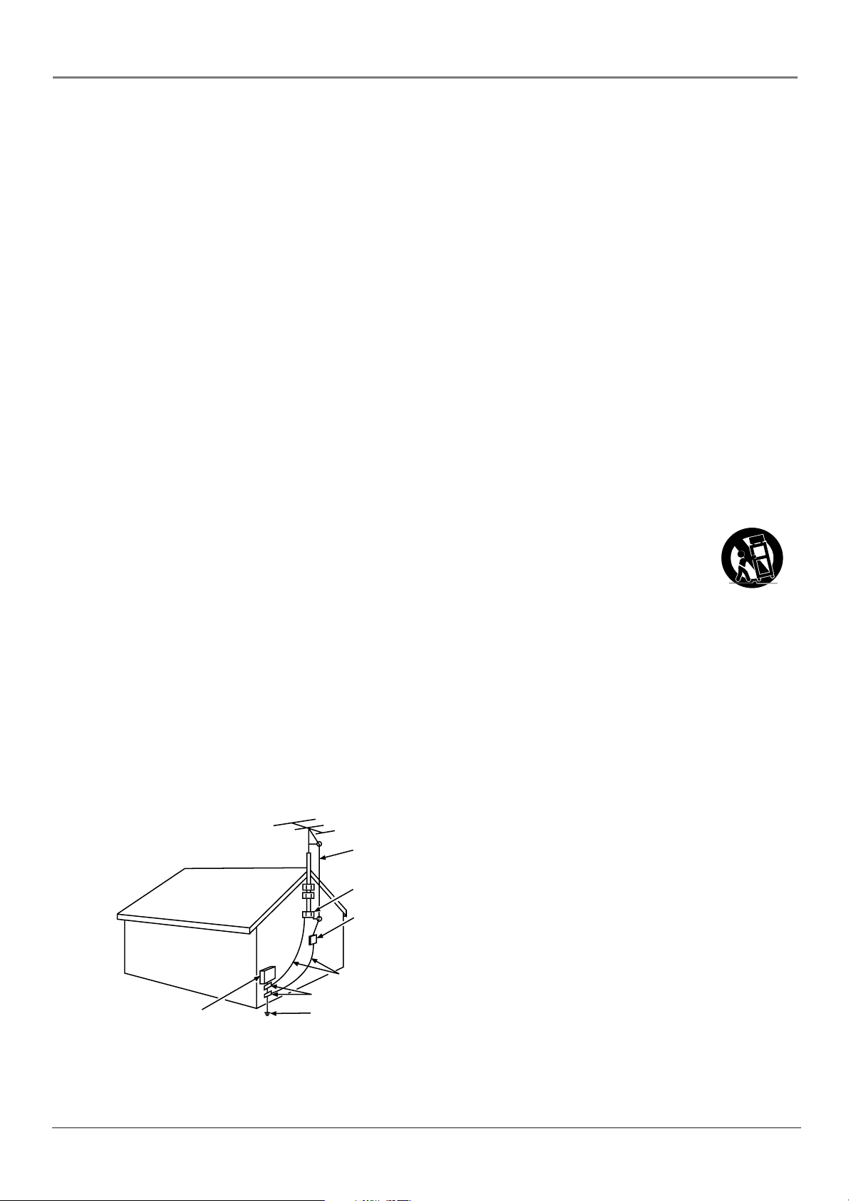
15. If an outside antenna or cable system is connected to the product, be sure the antenna or cable system is grounded
so as to provide some protection against voltage surges and built-up static charges. Section 810 of the National
Electrical Code, ANSI/NFPA No. 70-1984 (Section 54 of Canadian Electrical Code, Part 1) provides information
with respect to proper grounding of the mast and supporting structure, grounding of the lead-in wire to an
antenna-discharge unit, size of grounding conductors, location of antenna-discharge unit, connection to grounding
electrodes, and requirements for the grounding electrode. See following example.
ANTENNA
LEAD IN
WIRE
GROUND CLAMP
ANTENNA
DISCHARGE UNIT
(NEC SECTION 810-20)
GROUNDING CONDUCTORS
(NEC SECTION 810-21)
GROUND CLAMPS
ELECTRIC SERVICE
EQUIPMENT
POWER SERVICE GROUNDING
ELECTRODE SYSTEM
(NEC ART 250, PART H)
Important Information i
Page 4

This page intentionally left blank
Page 5

Table of Contents
Important Safety Instructions ....................................... i
Chapter 1: Connections and Setup
Things to Consider Before You Connect ..................... 6
Protect Against Power Surges ................................ 6
Protect Devices from Overheating ........................ 6
Position Cables Properly to Avoid Audio
Interference .......................................................... 6
Use Indirect Light .................................................... 6
Check Supplied Parts .............................................. 6
Attaching Your TV’s Base .............................................. 7
Mounting Your TV to the Wall ..................................... 7
Get the Picture .............................................................. 8
Getting Channels .................................................... 8
Choose Your Connection .............................................. 9
Video (Basic) Connection ..................................... 10
Component Video (Advanced) Connection ........10
HDMI Connection ................................................. 12
VGA Connection ................................................... 13
Plug in the TV .............................................................. 14
Put Batteries in the Remote ....................................... 14
Turn on the TV ............................................................. 14
How to Use the Remote Control to Complete the
Initial Setup ............................................................... 14
Complete the Initial Setup ......................................... 15
Set the Menu Language ...................................... 15
Set the Signal Source ............................................ 15
Complete the Channel Search ............................. 15
What To Expect ........................................................... 16
Watching TV ......................................................... 16
Changing Channels ............................................... 16
Explanation of Jacks (in alphabetical order) ............. 17
Buttons On Your TV ....................................................18
The Buttons on the Remote Control .......................... 19
Chapter 3: Using the TV's Menu System
Using the Menu System ............................................. 24
Setup Menu ................................................................. 24
Picture Menu ............................................................... 25
Audio Menu ................................................................. 26
Options Menu ............................................................. 27
Chapter 4: Other Information
Frequently Asked Questions (FAQs) .......................... 29
Troubleshooting .......................................................... 30
V-Chip Rating Explanations ........................................ 32
US V-Chip Rating System ...................................... 32
Canadian English V-Chip Rating System .............. 32
Canadian French V-Chip Rating System ..............33
Limited Warranty ........................................................ 34
Care and Cleaning ....................................................... 35
Chapter 2: Using the TV's Features
Channel Banner ........................................................... 20
Parental Controls and V-Chip ..................................... 20
How V-Chip Works for USA and Canada ............. 20
USA V-Chip TV Ratings ......................................... 22
V-Chip Movie Rating Limit ................................... 23
Blocking Canadian V-Chip Ratings ......................23
Blocking Unrated/Exempt Programs ................... 23
Future Rating Region ........................................... 23
5
Page 6

Chapter 1: Connections and Setup
Things to Consider Before You Connect
Protect Against Power Surges
• Connect all devices before you plug any of their power cords into the wall outlet or power
strip. NEVER plug your TV into an outlet that is controlled by a wall switch.
• Turn off the TV and/or device(s) before you connect or disconnect any cables.
• Make sure all antennas and cables are properly grounded. Refer to the Important Safety
Instructions at the beginning of the User's Guide.
Protect Devices from Overheating
• Don’t block ventilation holes on any of the devices. Arrange the devices so that air can
circulate freely.
• Don’t stack devices.
• If you place devices in a stand, make sure you allow adequate ventilation.
• If you connect an audio receiver or amplifi er, place it on the top shelf so the heated air
from it won’t fl ow around other devices.
Position Cables Properly to Avoid Audio Interference
• Insert each cable fi rmly into the designated jack.
• If you place devices above the TV, route all cables down the side of the back of the TV
instead of straight down the middle.
• If your antenna uses 300-ohm twin lead cables, do not coil the cables. Also, keep the twin
lead cables away from audio/video cables.
Use Indirect Light
Don’t place the TV where sunlight or room lighting will be directed toward the screen. Use soft
or indirect lighting.
Check Supplied Parts
Check that the following parts were packed with your product.
ON•OFF
PRESETS
CC
INPUT SUB CH
WATCH TV
VOL
VOL- VOL +
GO BACK FAV
MENU OK INFO
SOUND
FORMAT
CH +
MUTE
VOL
CH -
CLEAR
2 AA batteries
L19WD20 base
Remote control
Part # R130D1
Power cord
L15D20 base
Power adapter (only
available for model L15D20)
3 screws to attach base
(only available for
model L19WD20)
Note: If you need to replace your remote, call 1-800-338-0376. A shipping and handling
fee, and the appropriate sales tax, will be charged upon ordering. Have your Visa,
MasterCard, or Discover Card ready.
6 Chapter 1
Graphics contained within this publication are for representation only.
Page 7
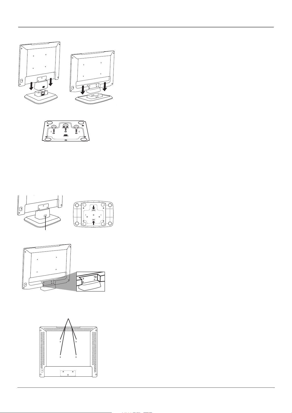
Model L15D20
Model L19WD20 bottom of the base
Model L19WD20
Connections and Setup
Attaching Your TV’s Base
Your TV comes shipped without the base attached so that you can
choose to mount your TV either to its base or to a wall (wall mount
sold separately). If you want to mount your TV to the wall, don’t
attach the base and instead follow the Mounting Your TV to the Wall
instructions below.
1. Locate the base. For model L19WD20, also locate the three screws.
2. For model L15D20, pick up the TV and align it so that the lock tab
on the base matches with the tab opening on the back of the TV.
For model L19WD20, the screw holes underneath the TV match
with the screw holes inside the base.
Push down on the top of the TV until it clicks into the base.
3. For model L19WD20, attach the three screws to the bottom of the
base as the picture to the left shows.
Mounting Your TV to the Wall
Model L15D20 tab
Remove the screws that attach to the TV's
base attachment.
Model L19WD20 tabs
Caution: The wall mount must bear a minimum of fi ve times
the TV’s net weight without causing damage.
To mount your TV to the wall you need to purchase a VESA wall
mount. Purchase a VESA 100 x 100, M4 x 10mm (100 x 100 means
the mounting measurements are 100mm horizontally and 100mm
vertically; M4 x 10mm is the type of screw).
1. If the base is attached, you need to remove it before attaching the
wall mount.
A. Place the TV facedown on a surface that is soft, yet strong
enough to hold the TV.
B. For model L15D20, push in on the tab at the back of the base
and remove the base from the TV.
For model L19WD20, remove the three screws from the bottom
of the base. Then, squeeze the two tabs on the bottom of the
base and remove the base from the TV.
C. Use a screwdriver to remove the screws from the holes as the
picture indicates to the left. Model L15D20 has three screws;
model L19WD20 has four screws.
Wall mount holes
2. Make sure all cables are already connected to the TV.
3. Attach the wall mount to the TV using the four holes on the TV's
back panel, as indicated in the picture to the left.
4. Follow the directions included with the wall mount to mount the
TV to the wall.
Chapter 1 7
Page 8
Connections and Setup
Get the Picture
The fi rst part of connecting your TV is to get the picture, also known
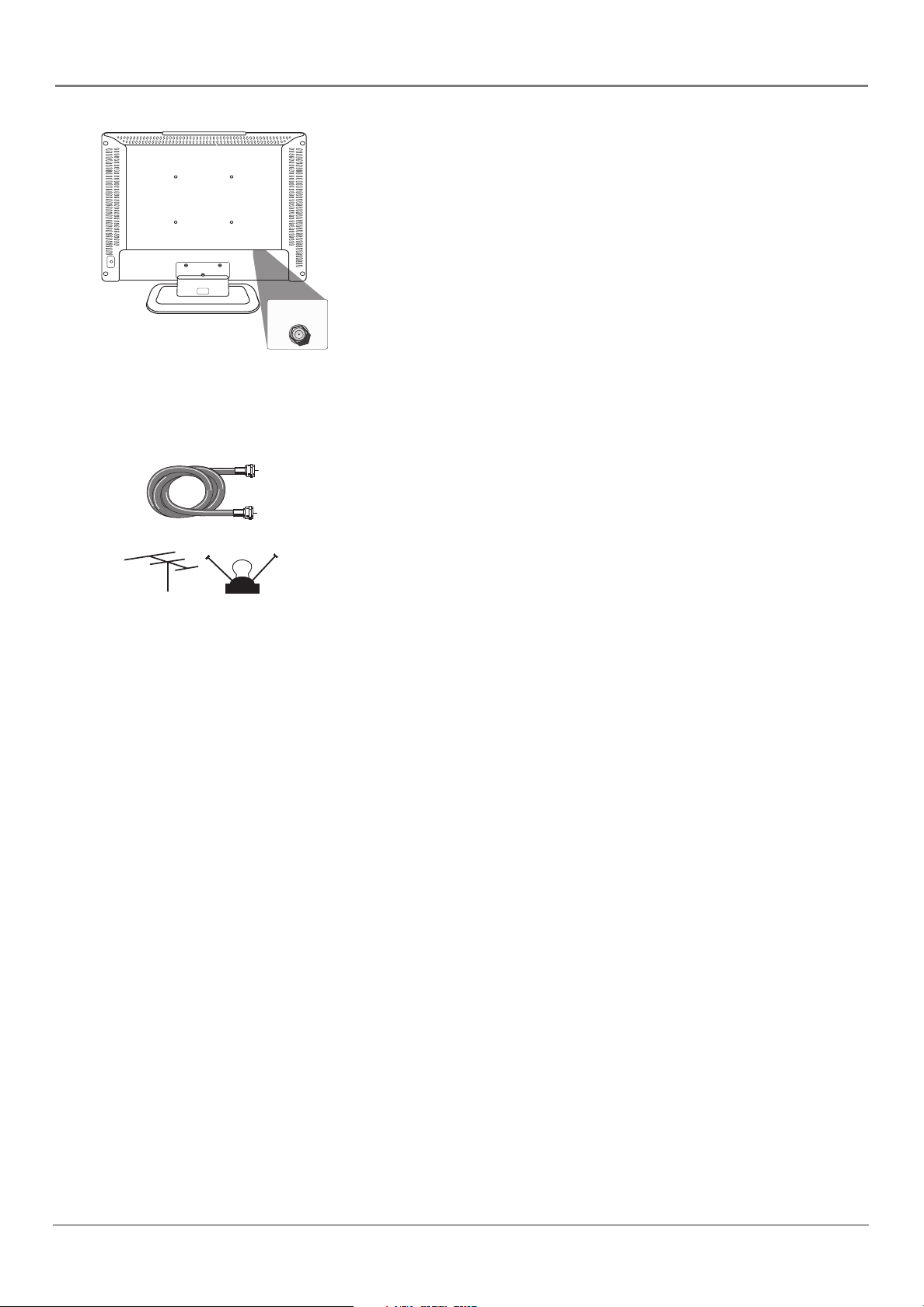
as the signal. The back panel of your TV allows you to receive analog
and/or digital channels by using the ANTENNA/CABLE INPUT.
ANTENNA/
CABLE INPUT
(DIGITAL AND ANALOG)
Getting Channels
What You Need
• Antenna (“rabbit ears”) or outdoor antenna with coaxial cable
OR
Coaxial cable
or
Outdoor or Indoor
antenna
• Coaxial cable with cable service
A. Do you have an indoor or outdoor antenna? If you don't, go to
B. Do you have cable? If you don't, go to step C. If you do, plug
C. Do you have a set-top box? If you do, you need to call your cable
step B. If you do, plug the antenna or coaxial cable from the wall
outlet into the ANTENNA/CABLE INPUT to receive free off-air
local digital and analog channels.
the coaxial cable from the wall outlet into the ANTENNA/CABLE
INPUT to receive your cable channels.
company or satellite service provider. They may use special cables
to allow you to view digital channels.
What You Need To Know
• Visit www.antennaweb.org to get help deciding what type of
antenna to use to receive the local digital channels available to
you. By entering where you live, this mapping program tells you
what local analog and digital stations are available using a certain
antenna.
• As you change channels, look at the top right corner of the screen
to see what type of channel you’re viewing. Digital channels
display a D as part of the channel, such as D Ch 29.1, while
analog channels display an A as part of the channel, such as
A Ch 9. Go to page 16 for more channel information.
8 Chapter 1
Page 9
Connections and Setup
Choose Your Connection
Note for US customers: If you prefer, we can provide you with the name of an Authorized Service Representative
who will visit your home for a fee to install your electronic entertainment system and to instruct you in its
operation. For details about this service, call 1-888-206-3359.
For additional assistance while using your RCA product, please visit www.rca.com/customersupport.
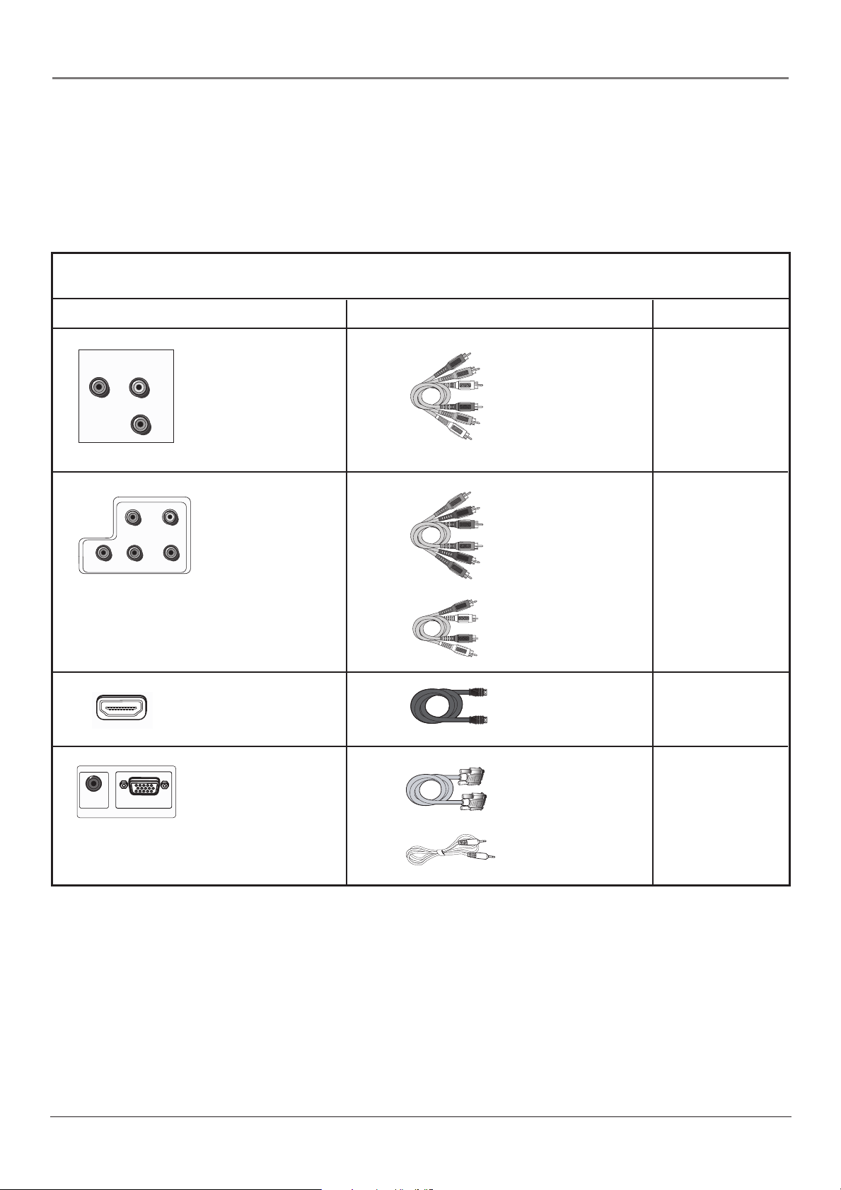
There are several ways to connect your TV. Please use the following chart to determine which connection is best
for you. Proceed to the appropriate page and connect your TV.
Jacks Used Cables Needed Go to...
COMPOSITE VIDEO INPUT
VIDEO
L
R
Video
Audio L and R
AUDIO
Audio/Video
page 10-11
Pb
Pr
COMPONENT VIDEO INPUT
(1080i/720p/480p/480i)
AUDIO
INPUT
PC INPUT
L
AUDIO
VGA INPUT
R
Y
HDMI
Y Pb Pr
Audio L and R
VGA
Audio
Component Video
Audio
HDMI™
VGA
Audio
page 10-11
page 12
page 13
HDMI, the HDMI logo, and High-Defi nition Multimedia Interface are trademarks or registered trademarks of HDMI
Licensing LLC.
Chapter 1 9
Page 10
Connections and Setup
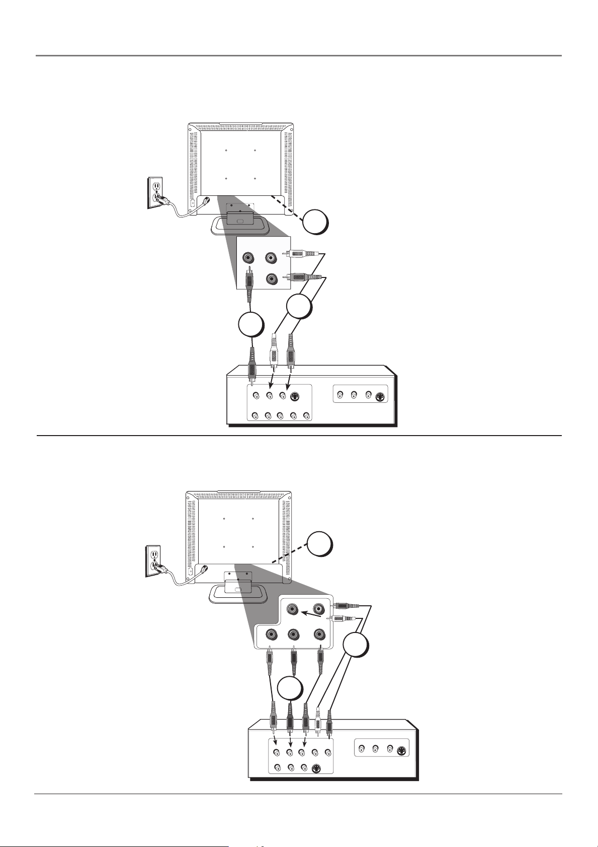
Video (Basic) Connection
This is an example of a connection using the Video jack. Go to the top of page 11 for specifi c
instructions.
Don't forget: If necessary,
connect antenna or cable to
1
COMPOSITE VIDEO INPUT
VIDEO L
2
AUDIO
R
3
get a picture. Go to page 8
for instructions.
OUTPUT
VIDEO
L
AUDIO
LR
S-VIDEO
AUDIO
R
COMPONENT VIDEO
YPbPr
INPUT
VIDEO
AUDIO
L
S-VIDEO
R
Component Video (Advanced) Connection
This is an example of a connection using the Component Video jacks. Go to the middle of
page 11 for specifi c instructions.
Don't forget: If necessary,
connect antenna or cable to
1
get a picture. Go to page 8
for instructions.
R
L
AUDIO
Pb
Pr
COMPONENT VIDEO INPUT
(1080i/720p/480p/480i)
Y
3
2
VIDEO
COMPONENT VIDEO
YPbPr
AUDIO
R
L
LR
S-VIDEO
OUTPUT
10 Chapter 1
AUDIO
INPUT
VIDEO
AUDIO
S-VIDEO
R
L
Page 11
Connections and Setup
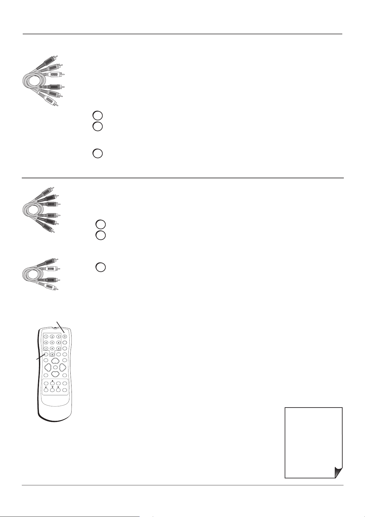
Red
Yellow
White
Composite cables are color
coded- Yellow= video;
Red= right audio; white=
left audio
Green
Blue
Red
Connecting the Device with Video (Basic)
This connection allows you to connect a device that has a Video Out jack, for example, a
DVD player.
Note: If the device you're connecting also has Component Video jacks and you have
component video cables, we recommend you use the Component Video (Advanced)
Connection instead. See the next set of instructions below.
Using the example of a DVD player:
1. If necessary, connect your cable and/or off-air antenna as described on page 8.
2. Connect your yellow video cable.
Connect a video cable to the VIDEO Input jack on the back of the TV and to the Video
Output jack on the DVD player.
3. Connect your red and white audio cables.
Connect the audio (red and white) cables to the AUDIO R and L jacks on the back of
the TV and to the Audio Output jacks on the DVD player.
Connecting the Device with Component Video (Advanced)
This connection allows you to connect a device that has Y Pb Pr jacks, for example, a DVD
player.
Using the example of a DVD player:
1. If necessary, connect your cable and/or off-air antenna as described on page 8.
Component Video cables
(Y Pb Pr) are color codedGreen, Blue and Red
Red
White
Audio cables are color
coded- Red= right audio;
white= left audio
ON•OFF button
ON•OFF
PRESETS
CC
INPUT
button
INPUT SUB CH
WATCH TV
GO BACK FAV
CH +
MUTE
VOL
VOL
VOL- VOL +
CH -
MENU OK INFO
SOUND
FORMAT
CLEAR
2. Connect your Y Pb Pr component video cables.
Connect three video cables or special Y Pb Pr cables to the COMPONENT VIDEO
INPUT Y Pb Pr jacks on the back of the TV and to the Y Pb Pr outputs on the
DVD player.
3. Connect your red and white audio cables.
Connect the audio (red and white) cables to the COMPONENT VIDEO INPUT
AUDIO R and L jacks on the back of the TV and to the Audio Output jacks on the
DVD player.
Viewing the Picture from the Connected Device
1. Plug in the TV (see page 14 for details) and the device, if they aren't already
plugged in.
2. Turn on the TV and the device you want to view, for example a DVD player.
3. Press the INPUT button on the remote control and press the up or down arrow button
to highlight Composite (if connected to the VIDEO jack) or Component (if connected
to the COMPONENT VIDEO jacks). Press OK to tune to the input. To go back to
viewing TV channels, press the WATCH TV button.
Note: If the picture from the DVD player appears black and white and your device
is connected to the VIDEO Input, you might be tuned to the wrong input. Make sure
you press INPUT and select Composite.
• If you're done
connecting devices to
Use these buttons
to view the picture
of the device you’ve
connected to the TV.
your TV, go to page 15
to complete the Initial
Setup.
• To continue
connecting devices, go
to the next page.
Chapter 1 11
Page 12

Connections and Setup
HDMI Connection
This is an example of a connection using the HDMI jack.
*
HDMI
INPUT
*Don't forget: If necessary,
connect antenna or cable to
get a picture. Go to page 8
for instructions.
Device with HDMI
L
Y
Video Out
Pb
R
Pr
Audio Out
HDMI Out
Connecting the Device
High-Defi nition Multimedia Interface (HDMI) technology is an uncompressed digital connection
that carries both video and audio data by way of an integrated mini-plug cable.
Using the example of a set-top box:
• If your set-top box has an HDMI output jack, connect an HDMI cable.
HDMI cable
Connect an HDMI cable to the HDMI INPUT on the back of the TV and to the HDMI
Out jack on the back of the device.
ON•OFF button
Viewing the Picture from the Connected Device
The device in this connection is connected to the HDMI INPUT jack. To view this device:
INPUT SUB CH
WATCH TV
INPUT
button
CH +
MUTE
VOL
VOL- VOL +
CH -
GO BACK FAV
MENU OK INFO
Use these buttons
to view the picture
of the device you’ve
connected to the TV.
ON•OFF
PRESETS
CC
SOUND
FORMAT
VOL
CLEAR
1. Plug in the TV (see page 14 for details) and the device, if they aren't already
plugged in.
2. Turn on the TV and the device you want to view, for example a set-top box.
3. Press the INPUT button on the remote control and press the up or down arrow
button to highlight HDMI from the input list. Press OK to tune to the input. To go
back to viewing TV channels, press the WATCH TV button.
• If you're done
connecting devices to
your TV, go to page 15
to complete the Initial
Setup.
• If you experience HDMI
problems, go to the
HDMI Troubleshooting
section on page 31.
12 Chapter 1
Page 13

VGA Connection
This is an example of a connection using the VGA jacks.
AUDIO
INPUT
Connections and Setup
1
Don't forget: If necessary,
connect antenna or cable
to get a picture. Go to
page 8 for instructions.
VGA INPUT
PC INPUT
3
2
Connecting the Device
This connection allows you to connect to a personal computer.
1. If necessary, connect your cable and/or off-air antenna as described on page 8.
2. Connect your monitor cable.
Connect one end of a 15-pin monitor cable to the VGA INPUT jack on the TV and the
other end to the PC's video output jack. Note, if your PC's video output isn't 15-pin, you'll
need an adapter that can connect to a 15-pin monitor cable.
3. Connect your audio cable.
Connect a 3.5 mm stereo mini pin cable (sometimes referred to as 1/8" stereo mini pin) to
the VGA AUDIO INPUT jack on the back of the TV and the other end to the Audio Output
jack on the PC.
Notes: The maximum panel resolution is 1366 x 768 for your TV. Be sure to set your
PC to the correct monitor output setting.
The TV allows you to listen to the sound from another input while the PC is connected.
Go to page 26 for more information.
Viewing the PC
1. Plug in the TV (see page 14 for details) and the PC, if they aren't already plugged in.
2. Turn on the TV and the PC.
3. Press the INPUT button on the remote control and press the up or down arrow button to
highlight VGA from the input list. Press OK to tune to the input. To go back to viewing TV
channels, press the WATCH TV button.
Chapter 1 13
Page 14

Connections and Setup
Plug in the TV
Plug the end of the power cord into the back of the TV. For model L15W20, plug the power
cord into the power adapter, then plug the power adapter into the TV. Plug the other end of
the power cord into a grounded wall outlet. Insert the plug completely into the outlet. Do not
plug into an outlet controlled by a light switch.
Put Batteries in the Remote
• Remove the battery compartment cover from the back of the remote by pushing the tab
and lifting off the cover.
• Insert two fresh batteries. Make sure the polarities (+ and -) are aligned correctly.
• Replace the cover.
Turn on the TV
Turn on your TV by pressing the Power button on the top panel of the TV or ON•OFF on the
remote control.
ON•OFF
CH +
MUTE
CH -
SOUND
FORMAT
VOL
CLEAR
INPUT SUB CH
WATCH TV
VOL
VOL- VOL +
GO BACK FAV
MENU OK INFO
PRESETS
CC
OK
button
Arrows
How to Use the Remote Control to
Complete the Initial Setup
The technical term is “Navigation” – how you move through the onscreen menus. The theory is the same throughout the menu screens:
highlight your choice and select it.
With the Setup menu displayed, press the right arrow button to access
the Setup menu choices. Press the up or down arrow button to move
up or down within the menu. Items with an arrow (4) means there
are more items to choose from or a sub-menu available. Press the right
arrow or OK to display these.
Note: Highlighted means that the menu item stands out from other
menu items on the list (appears darker, brighter, or a different color).
14 Chapter 1
Page 15

Connections and Setup
Complete the Initial Setup
Customizing items in the Setup menu allows your TV to perform correctly. Make sure you've
connected the TV to cable or an off-air signal before you continue.
Setup
Signal Source Cable TV
DTV Signal Strength
Auto Channel Search Start
Manual Channel Setup
Channel Labels
Menu Language English
Screen Format Stretch
Favorite Channel Off
To Move
Signal Source Cable TV
DTV Signal Strength
Auto Channel Search Start
Manual Channel Setup
Channel Labels
Menu Language English
Screen Format Stretch
Favorite Channel Off
To Move
Auto Channel Search Menu
Analog TV Channel 30: Found
Channels Found: 25
Progress: 30%
OK To Select
Setup
OK To Select
MENU To Exit
MENU To Exit
u
u
u
u
u
u
If you have ANALOG and DIGITAL channels,
the TV runs 2 separate channel searches.
Set the Menu Language
If English is your preferred language, skip this step and go to Set the
u
Signal Source.
u
To choose another language, press the MENU button then press the
right arrow button to enter the Setup menu. Press the down arrow
u
u
to highlight Menu Language, then press the right arrow to choose a
u
language. Continue to Set the Signal Source.
Set the Signal Source
From the Setup menu, press the up or down arrow button to highlight
u
Signal Source. If you connected Cable to your ANTENNA/CABLE
u
INPUT, the option is chosen for you and you can press the down
arrow button to highlight Auto Channel Search. To choose Air
u
(Antenna), press the right arrow button and then press the down
u
arrow button to highlight Auto Channel Search.
u
Complete the Channel Search
Even though the initial channel search can take time, you must
complete it in order for your TV to display channels and programming.
With Auto Channel Search highlighted, press OK to begin the channel
search. The menu shows the TV is running a channel search. The TV
tunes to a program once the search is complete.
Some channels might have been found during the channel search that
are unavailable to view and you might want to get rid of these so they
don't appear as you change channels. To do this, highlight Manual
Channel Setup from the Setup menu. Note that removing channels
from your channel list may be time consuming, so you might want to
do it later. Go to page 24 for details on editing your channel list.
Chapter 1 15
Page 16

Connections and Setup
What To Expect
Watching TV
• Your TV allows you to change the format of the picture you're viewing by pressing the
FORMAT button on your remote or accessing the Screen Format option in the Setup menu.
The format changes as you press the FORMAT button and the format type is displayed
at the top of the screen. Depending on the type of signal you're viewing and your TV's
model, a different format might not be available.
• Analog video is sent in a 4/3 format. Most digital video is sent in a 16/9 format, but
sometimes is sent in 4/3. It depends on how the station or device connected to your TV
is formatting the video. If there are bars on-screen, press the FORMAT button to try a
different format that may eliminate the bars.
Changing Channels
• If you have both analog and digital channels, these are put into the same channel list.
As you change channels, look at the top right corner of the screen to see what type of
channel you’re viewing. Digital channels display a D as part of the channel, such as
D Ch 29.1, while analog channels display an A as part of the channel, such as A Ch 9.
• Digital channels can have both primary channels (like the analog channel number) and
subchannels. If 6 is the primary channel and 1 is the subchannel, for example, the channel
looks like 6.1 on screen. To tune to a digital channel with a subchannel, such as 6.1, enter
the primary channel number (6), then press the SUB CH button. Enter the subchannel
number (1) and press OK.
• Depending upon the type of signal you have connected to your HDTV, you might notice
that the channels change slower than you’re used to. This is perfectly normal. Digital
channels sometimes take longer to tune.
16 Chapter 1
Page 17

Connections and Setup
Explanation of Jacks (in alphabetical order)
This section describes the jacks on the back panel of your TV. There are several ways to
connect devices.
L
AUDIO
R
DIGITAL AUDIO
OUTPUT (COAXIAL)
Pr
COMPONENT VIDEO INPUT
L
AUDIO
Pb
(1080i/720p/480p/480i)
R
ANTENNA/
Y
AUDIO
INPUT
VGA INPUT
PC INPUT
CABLE INPUT
(DIGITAL AND ANALOG)
HDMI
INPUT
HEADPHONE
COMPOSITE VIDEO INPUT
VIDEO
S-VIDEO
INPUT
ANTENNA/CABLE INPUT Lets you connect a coaxial cable to receive the signal from the
antenna, cable, or cable box.
COMPONENT VIDEO INPUT Lets you connect a device that has component video jacks,
such as a DVD player.
• COMPONENT L AUDIO Provides left audio connection when using COMPONENT VIDEO
INPUT. The left audio connector is usually white.
• COMPONENT R AUDIO Provides right audio connection when using the COMPONENT
VIDEO INPUT. The right audio connector is usually red.
• COMPONENT VIDEO Y Pb Pr Provides optimum picture quality because the video is
separated into three signals. Use three video-grade or component video cables for the
connection. When using Y Pb Pr, make sure you connect left and right audio cables to the
COMPONENT L and R AUDIO jacks.
COMPOSITE VIDEO INPUT Lets you connect a device that has composite video jacks, such
as a video game console, VCR, or DVD player.
• AUDIO L and R Receives audio from another device such as a camcorder, video game
console, VCR, or DVD player. Use when connecting to the VIDEO or S-VIDEO Input.
• S-VIDEO Allows you to connect an S-Video cable from another device. Make sure you
also connect audio cables from the device to the TV.
• VIDEO Receives video from another device such as a camcorder, video game console,
VCR, or DVD player.
Note: Do not connect an S-Video and a regular video cable at the same time.
DIGITAL AUDIO OUTPUT (COAXIAL) Use this jack to connect an audio receiver to the TV
for enhanced sound quality. Make sure you set the Audio output correctly in the Advanced
Audio Menu. Go to page 26 for more information.
HDMI INPUT (High-Defi nition Multimedia Interface) Provides an uncompressed digital
connection that carries both video and audio data by way of an integrated mini-plug cable.
Lets you connect a device, such as a digital cable box, with an HDMI output.
HEADPHONE Allows you to connect headphones to listen to the sound coming from the TV.
The TV speakers turn off when you plug in headphones.
VGA AUDIO INPUT (Stereo mini jack) Use to obtain sound when a device is connected to
the VGA jack. Use a 3.5 mm stereo mini pin cable (sometimes referred to as 1/8” stereo mini
pin) to connect a device to your TV. Go to page 13 for more information.
VGA INPUT Connect your computer, or other device with a VGA output, to this jack using a
15 pin D-sub cable.
Chapter 1 17
Page 18

Connections and Setup
▲
MENU CH INPUT/OKVOL
▲
▲
▲
If you cannot locate your remote, you can use the buttons on the top
of your TV to operate many of the TV’s features.
MENU Displays the TV Main menu. If the main menu is displayed,
exits the menu; if a sub menu is displayed, takes you back to the
previous menu.
>
CH Scans down through the channel list. In the TV menu system,
acts like the down arrow button on the remote control and adjusts
menu controls.
>
CH Scans up through the channel list. In the TV menu system,
acts like the up arrow button on the remote control and adjusts menu
controls.
POWER Turns the TV on and off.
VOL < Decreases the volume. In the TV menu system, acts like the
left arrow button on the remote control and adjusts menu controls.
VOL > Increases the volume. In the TV menu system, acts like the
right arrow button on the remote control and adjusts menu controls.
INPUT/OK Displays the available video input channels- Watch TV,
Composite, S-Video, Component, VGA, and HDMI. When in the menu
system, displays sub-menus and selects the highlighted item
.
Buttons On Your TV
18 Chapter 1
Page 19

ON•OFF
Connections and Setup
The Buttons on the Remote Control
Arrows Used to move and highlight different items in the TV menu
and to adjust the menu controls.
PRESETS
INPUT SUB CH
WATCH TV
CH +
MUTE
VOL
VOL- VOL +
CH -
GO BACK FAV
MENU OK INFO
SOUND
FORMAT
VOL
CLEAR
CC
(0-9) Number Buttons Enter channel numbers. To enter a digital
channel with a sub-channel, enter the main channel, then press the
SUB CH button to enter the sub-channel and press OK.
CC Toggles through the CC settings: CC Off, CC On, and CC On
When Mute.
CH + or CH - Scan up or down through the current channel list. Press
once to change the channel up or down; press and hold to continue
changing channels.
CLEAR Removes any menu or display from the screen and returns
you to normal viewing.
FAV (Favorite) Press to browse the channels set in your Favorite
Channel list. Go to page 25 for more information.
FORMAT Press to change the size of the picture on-screen.
GO BACK Returns you to the previous channel.
INFO Brings up the channel banner; press again to clear the screen.
INPUT Displays the available video input channels- Watch TV,
Composite, S-Video, Component, VGA, and HDMI.
MENU Displays the TV Main menu. If the main menu is displayed,
exits the menu; if a sub-menu is displayed, takes you back to the
previous menu.
Remote control part number
R130D1
Note: If you need to replace your
remote, call 1-800-338-0376. A
shipping and handling fee, and the
appropriate sales tax, will be charged
upon ordering. Have your Visa,
MasterCard, or Discover Card ready.
MUTE Reduces the TV’s volume to its minimum level. Press again to
restore the volume.
OK When in the menu system, displays sub-menus and make
selections.
ON•OFF Turns the TV on and off.
PRESETS Toggles through the picture mode settings: Natural,
Vibrant, Gaming, and Personal.
SOUND For an Analog channel, switches the sound mode options.
For a Digital channel, switches the audio language. In VGA mode,
switches to the audio input you selected from the VGA Sound Source
option.
SUB CH When entering a digital channel that has a subchannel, press
this button to enter a subchannel. Once the channel is entered, press
the OK button to tune to the channel.
VOL – or VOL + Decreases or increases the TV’s volume.
WATCH TV Switches back to watching a TV channel if you're tuned
to an input.
Chapter 1 19
Page 20

Chapter 2: Using the TV's Features
Channel Banner
There are several indicators that might appear when you press the INFO button on the remote.
This display is called the Channel Banner. The following list describes the items on the Channel
Banner screen (left to right and top to bottom).
A Ch 70 LPJ 12:15 PM
Crafty Lady
480i Stereo
Analog Channel Banner
D Ch 700 BEV 12:15 PM
Ides of March
1080i TV-PG
Digital Channel Banner
A Ch 70 LPJ/D Ch 700 BEV The channel and station you're currently viewing are displayed.
An A displayed means it's an analog channel; a D displayed
means it's a digital channel. Digital channels may also display an
HD (High Defi nition), SD (Standard Defi nition), or DT (Digital
Television) at the end of the station.
12:15 PM Current time that you set under the Set Time option in the
Options menu.
Program name The program name appears, if available.
480i/1080i Current resolution is displayed.
TV-PG The program rating appears, if available.
Stereo Current audio the channel is broadcasting.
Options
Set Time
Sleep Timer Off
Set Password
Parental Controls
Analog Captions CC1
Digital Captions Text1
Digital Caption Setup
u
u
u
u
u
u
u
Parental Controls and V-Chip
The choices in the USA Parental Controls and Canada Parental
Controls menus involve software inside your TV (referred to as V-Chip)
which allows you to block TV programs and movies. TV programs can
be blocked by age-based ratings, such as TV-MA, which is explained
on page 22. If available, TV programs can also be blocked by content,
such as adult language (L). This is explained on page 22. Movies can
To Move
OK To Select
MENU To Exit
only be blocked by age-based ratings. This is explained on page 23.
Once you block programs, you can unblock programs by entering a
password.
By default, the software inside your TV is turned off or unlocked. For
instructions to lock V-Chip, go to the next page.
Note: Parental control settings are not available for HDMI or
COMPONENT inputs.
Parental Controls Menu
USA Parental Locks
Canada Parental Locks
Unrated Programs Unlocked
u
u
u
How V- Chip Works for USA and Canada
V-Chip reads the program’s age-based rating (TV-MA, TV-14, etc.) and
content themes [(Violence (V), Adult Language (L), etc.)]. If you have
blocked the rating and/or content themes that the program contains,
you will receive the message This program is blocked. Press MENU
key to enter password. Go to page 32 for the US and Canada ratings
explanations.
Broadcasters are not required to provide content themes, so programs
To Move
OK To Select
MENU To Exit
received with no content themes will only be blocked if you block
their age-based rating. You can also block out programs that have been
given a rating of None for TV Ratings, N/A or N/R for Movies, or E
(Exempt) for Canadian ratings. Go to page 23 for unrated explanation.
20 Chapter 2
Graphics contained within this publication are for representation only.
Page 21

Using the TV’s Features
Lock/Unlock Parental Controls
The default password for Parental Controls is "0000". You probably want to change the
password to something less obvious, yet easy for you to remember. To change the password,
access the Options menu (lock icon) and press the right arrow to enter the menu. Press the up
or down arrow button to highlight Set Password and press OK. Press 0, 0, 0, and 0 as the old
password and then enter the new password you want to use.
If you forget your password, select Set Password from the Options menu and press OK. Press 3,
4, 4, and then 8. Then enter a new password you want to use.
The V-Chip Rating Screen
The following is an example of where items are located within the Rating Limit screen.
Rating Status Field
Lets you select whether the status of the
age-based rating limit to the left is locked
) or unlocked ( ).
(
Rating Field
Lists the age-based
ratings of Movies
and TV programs.
USA Parental Locks
Movies (MPAA) TV Ratings
All FV L S V D
Reset Reset
G TV-Y
PG TV-Y7
PG-13 TV-G
R TV-PG
NC-17 TV-14
X TV-MA
To Move
OK To Select
MENU To Exit
Content Status Fields
Lets you select whether the status of the
content theme is currently locked (
unlocked (
).
Content Themes
Lists the content themes of
TV programs you can block
or view. See next page for
explanation.
) or
Chapter 2 21
Page 22

Using the TV’s Features
Hierarchy of Age-Based Ratings
TV-MA Mature Audience Only
TV-14 Parents Strongly Cautioned
TV-PG Parental Guidance Suggested
TV-G General Audience
TV-Y7 Directed to Children 7 years and older
TV-Y All Children
USA Parental Locks
Movies (MPAA) TV Ratings
All FV L S V D
Reset Reset
G TV-Y
PG TV-Y7
PG-13 TV-G
R TV-PG
NC-17 TV-14
X TV-MA
To Move
OK To Select
MENU To Exit
USA V-Chip TV Ratings
Blocking Age-Based Ratings
You can automatically block all program ratings above a specifi ed agebased rating level.
1. Choose Options (lock icon) from the main menu, then highlight
Parental Controls. Enter your password.
2. Highlight and select USA Parental Locks.
3. Press the left or right arrow button to highlight a TV Rating. Press
the up or down arrow button to scroll to the rating corresponding
with the lowest rating you do not want the child to watch. In the
example to the left, highlight TV-Y.
4. Press the OK button to toggle between locked and unlocked. The
status for the rating and all higher ratings automatically lock.
To view age-based ratings after you've locked them, follow the same
steps as above to unlock.
Content Themes
D Sexually explicit dialogue
L Adult language
S Sexual situations
V Violence
FV Fantasy Violence
USA Parental Locks
Movies (MPAA) TV Ratings
All FV L S V D
Reset Reset
G TV-Y
PG TV-Y7
PG-13 TV-G
R TV-PG
NC-17 TV-14
X TV-MA
To Move
OK To Select
MENU To Exit
Blocking Specifi c Content Themes
You can block programs based on their content. (Content is
represented by the FV, L, S, V and D on your screen.) When you block
a content theme for a particular rating, you automatically block that
content theme for higher rated programs as well.
To block program content:
1. Determine the content theme you want to block.
2. Press the down arrow button to scroll to the rating whose content
theme you want to change.
3. Press the right arrow button to move the highlight to a particular
content theme. In the example to the left, highlight the language
(L) corresponding with TV-14.
4. Press the OK button to change its status to lock. The language for
TV-MA is blocked as well.
Notes: Broadcasters are not required to provide content
themes or age-based ratings.
To view a content theme after it's been locked, follow the same
steps as above to unlock. Note that if you unlock the language
corresponding with TV-14, the language for TV-MA doesn't unlock.
You have to unlock the content theme status for each rating separately.
22 Chapter 2
Page 23

Using the TV’s Features
USA Parental Locks
Movies (MPAA) TV Ratings
All FV L S V D
Reset Reset
G TV-Y
PG TV-Y7
PG-13 TV-G
R TV-PG
NC-17 TV-14
X TV-MA
To Move
Canada Parental Locks
English Rating French Rating
Reset Reset
C G
C8+ 8 ans+
G 13 ans+
PG 16 ans+
14+ 18 ans+
18+
To Move
OK To Select
OK To Select
MENU To Exit
MENU To Exit
V-Chip Movie Rating Limit
Set movie rating limits by blocking movies rated above a specifi ed
level.
To access Movie Ratings:
1. Press MENU on the remote control.
2. Choose Options (lock icon) from the main menu, then highlight
Parental Controls. Enter your password.
3. Highlight and select USA Parental Locks.
4. The Movie Ratings appear on the left side of the menu. Press the
up or down arrow button to highlight a rating.
Blocking Movie Ratings
Once you are in the Movie ratings menu, follow the same steps
described for blocking USA age-based ratings.
Blocking Canadian V-Chip Ratings
If you receive Canadian programs you can block Canadian English
and French V-Chip by ratings only. When you block a particular rating,
you automatically block the higher rated programs as well.
To block Canadian English and French program ratings:
1. Select Canada Parental Locks from the Parental Controls menu.
2. Determine the rating you want to block from English on the left or
French on the right.
3. Press the down arrow button to scroll to the rating you want to
change.
Parental Controls Menu
USA Parental Locks
Canada Parental Locks
Unrated Programs Unlocked
To Move
OK To Select
u
u
u
MENU To Exit
4. Press the OK button to change its status to block (all ratings above
the one you selected change to block).
Blocking Unrated/Exempt Programs
Unrated TV programs may include news, sports, political,
religious, local and weather programs, emergency bulletins, public
announcements, and programs without ratings. Programs that have no
rating or have been given a rating of None for TV Ratings, N/A or N/R
for Movies, or E (Exempt) for Canadian ratings can be blocked using
the Unrated Programs option.
Future Rating Region
You might notice an option in the Parental Controls menu that wasn't
there before. This is because broadcasters have the capability to add
a new rating system for TV programs. These ratings let you defi ne
additional parameters for parental controls. This option and its name
are dependent on the content acquired from the broadcaster.
Note: These ratings are available only if the broadcaster is
sending them.
Chapter 2 23
Page 24

Chapter 3: Using the TV's Menu System
Setup
Signal Source Cable TV
DTV Signal Strength
Auto Channel Search Start
Manual Channel Setup
Channel Labels
Menu Language English
Screen Format Stretch
Favorite Channel Off
To Move
OK To Select
MENU To Exit
Using the Menu System
u
u
u
u
This section explores the menus of your TV. Each menu is outlined and
detailed to help you get the most from your TV. The Parental Controls
u
menu is discussed in the Features chapter.
u
To access the menu system:
u
u
1. Press the MENU button.
2. Use the up and down arrow buttons to highlight an icon on the left
and press the right arrow button to enter the menu. The name of
the menu is displayed at the top of the menu screen.
3. Press the up and down arrow buttons to move to a different option
within the menu. If necessary, press the OK button or right arrow
to display the choices of the option you’ve highlighted or toggle
through available options. If available, use the information at the
bottom of the screen for help.
4. To adjust controls, such as picture setting options, highlight the
option and press OK. The option appears on the bottom of the
screen so you can see the option change as you adjust it.
5. To return to the previous menu, press the MENU button.
Note: Options in the menus that are grayed-out and can't be
highlighted are unavailable or in progress.
Setup
Signal Source Cable TV
DTV Signal Strength
Auto Channel Search Start
Manual Channel Setup
Channel Labels
Menu Language English
Screen Format Stretch
Favorite Channel Off
To Move
OK To Select
MENU To Exit
Descriptions of each menu are discussed in the order they appear.
There are two ways to exit a menu:
• Press the CLEAR button. The menus are cleared from the screen and
you return to TV viewing.
• Press the MENU button repeatedly until the menus disappear.
Setup Menu
u
u
u
u
The Setup menu lets you confi gure the TV to fi t its surroundings and
your preferences. To access the Setup menu (plug icon), press MENU
u
on the remote (the Setup icon is highlighted). Press the right arrow
button or OK to enter the menu.
u
u
Signal Source If you connected cable to the ANTENNA/CABLE
u
INPUT, select Cable TV. If you connected an antenna to the ANTENNA/
CABLE INPUT, select Air (Antenna).
DTV Signal Strength Displays the signal strength of the digital
channel that the TV is currently tuned to.
Auto Channel Search Searches for channels the signal is receiving.
Go to page 15 for more information.
Manual Channel Setup Displays the channel list, allowing you
to add or delete channels. If a channel is Hidden and you want it
viewable as you change channels, select Viewable. If a channel is
Viewable and you don't want it to appear as you change channels,
select Hidden.
24 Chapter 3
Graphics contained within this publication are for representation only.
Page 25

Using the TV's Menu System
Setup
Signal Source Cable TV
DTV Signal Strength
Auto Channel Search Start
Manual Channel Setup
Channel Labels
Menu Language English
Screen Format Stretch
Favorite Channel Off
To Move
Picture Preset Mode Personal
Contrast 50
Brightness 51
Sharpness 0
Color 50
Tint 0
Backlight 10
Advanced Picture Menu
VGA Settings
To Move
Advanced Picture Menu
Video Noise Filter Low
Color Temperature Warm
3D Comb Filter On
Reset All Reset
OK To Select
Picture
OK To Select
MENU To Exit
MENU To Exit
Channel Labels Allows you to add or change a seven character
label to a channel, which is displayed on-screen when you tune to
u
u
u
u
u
the channel. Press the up and down arrow button to scroll through
the available characters. Continue to press the right arrow button to
highlight the next space to add another character.
u
Menu Language Allows you to change the language of the menu
u
system.
u
Screen Format Allows you to change the format of the screen. If
there are bars on-screen try a different format, if available, that may
eliminate the bars. Choose between Normal, Zoom, Stretch (only
available for model L19WD20), and Center.
Favorite Channel The channel you're tuned to is saved as a favorite
channel when you turn the setting On. You can have up to 10 favorite
channels. Then use your FAV button on the remote to scroll through
your favorite channels.
Picture Menu
u
The Picture menu contains menus and controls to confi gure how the
picture looks. To access the Picture menu (person icon) press MENU
on the remote, and then press the down arrow button to highlight
the Picture icon. Press the right arrow button or OK to enter the
menu. Picture options can be applied to each input- VIDEO, SVIDEO,
u
u
COMPONENT, VGA, and HDMI.
Picture Preset Mode Displays a choice list that lets you select one
of the preset picture settings: Vibrant, Cinematic, Natural, Sports,
Videogame, Video camera or Personal. Choose the setting that is best
for your viewing environment.
Contrast Adjusts the difference between the light and dark areas of
the picture.
Brightness Adjusts the brightness of the picture.
Sharpness (not available in VGA mode) Adjusts the crispness of
the edges in the picture.
Color (not available in VGA mode) Adjusts the richness of the
color.
Tint (not available in VGA mode) Adjusts the balance between red
and green levels.
Backlight Adjusts the level of light, depending on your room setting.
Note: When you change any of these picture settings, the
Picture Preset Mode changes to Personal.
Advanced Picture Menu
Video Noise Filter Reduces picture “static” or any type of
u
u
u
u
interference. This feature is especially useful for providing a clearer
picture in weak analog signal conditions. Choose between Off for
no noise reduction; Low for a softer, smoother picture that retains
picture sharpness and detail; Medium for a slightly softer picture
than the Low setting; High for an even softer, smoother picture
than the other settings (the picture detail is somewhat decreased).
Note: Video noise fi lter is available for the COMPONENT VIDEO
To Move
OK To Select
MENU To Exit
input only if the signal is 480i.
Chapter 3 25
Page 26

Using the TV's Menu System
Color Temperature Adjusts to make the picture appear more
red or blue. Choose War m for more red, Normal for standard
picture, and Cool for more blue.
3D Comb Filter If you have a device connected to the VIDEO
INPUT, helps to correct detail and color loss. Turn the option On
for improved video.
Reset All Restores Advanced Picture Menu to the default settings.
VGA Settings Menu
Horizontal Position 50
Vertical Position 50
Clock 50
Phase 50
Auto Adjustment Adjust
Reset All Reset
To Move
To Move
Advanced Audio Menu
Audio Language English
Digital Audio Output Digital
TV Speakers On
VGA Sound Source VGA
Reset All Reset
To Move
OK To Select
Audio
Bass 30
Treble 30
Balance 0
Advanced Audio Menu
Reset All Reset
OK To Select
OK To Select
MENU To Exit
MENU To Exit
MENU To Exit
VGA Settings (only available in VGA mode)
Horizontal Position Adjusts the picture's position left or right.
Vertical Position Adjusts the picture's position upward or
downward.
Clock Adjusts the clock sync of the picture.
u
Phase Adjusts the picture if there is fl icker of screen letters,
u
color misalignment, or blurring.
Auto Adjustment Adjusts the position of the picture
automatically. Try it if the picture on the VGA input doesn't look
right.
Reset All Restores VGA Settings menu to the default settings.
Audio Menu
The Audio menu lets you adjust audio output. To access the Audio
menu (speaker icon), press MENU on the remote, and then press the
u
down arrow button to highlight the Audio icon. Press the right arrow
u
button or OK to enter the menu. The following audio items can be
adjusted:
Bass Increases or decreases the bass of the sound.
Treble Increases or decreases the treble of the sound.
Balance Adjusts how much audio is sent to the left and right
speakers.
Advanced Audio Menu
Audio Language (only available on digital channels) Press
u
u
u
u
u
the right arrow to choose from the audio languages available for
the program you're watching. The language you choose becomes
your preferred audio language for all channels on the digital tuner
until you turn the TV off. If the language you choose here is not
being broadcast with a program, then the TV plays the default
audio for the program (usually English in the U.S.).
Digital Audio Output Lets you choose a setting for the
DIGITAL AUDIO OUTPUT jack. Choose Digital to receive Dolby
Digital sound if transmitted and you've connected a six-channel
receiver to the TV's output jack. Choose for PCM if your audio
receiver only handles PCM.
TV Speakers Turn on or off the internal speakers. If you have
an audio amplifi er device connected to the DIGITAL AUDIO
OUTPUT jack on the back of the TV and you want to control the
sound by the audio amplifi er device instead, turn the option Off.
VGA Sound Source Allows you to listen to the audio from the
VGA, COMPOSITE, or COMPONENT inputs while tuned to the
VGA input. Make sure the device connected to the input is turned
on and the audio you want to hear is playing.
26 Chapter 3
Page 27

Using the TV's Menu System
Reset All Restores the Advanced Audio Menu to the default
settings.
Reset All Restores the Audio Menu to the default settings.
Options
Set Time
Sleep Timer Off
Set Password
Parental Controls
Analog Captions CC1
Digital Captions Text1
Digital Captions Setup
To Move
OK To Select
u
u
u
u
MENU To Exit
Options Menu
u
u
u
The Options menu lets you adjust additional options for the TV. To
access the Options menu (lock icon), press MENU on the remote, and
then press the down arrow to highlight the Options icon. Press the
right arrow button or OK to enter the menu. The following options can
be adjusted:
Set Time Lets you set the time zone and time.
Time Press the left or right arrow to set the time. The AM and PM
setting changes when you get to 12 o'clock.
Note: If your TV loses power, you need to reset the time.
Sleep Timer Lets you set the TV to turn off after a given amount of
time. Choose between Off, 30 min, 60 min, or 90 min.
Set Password Set the password used to lock parental controls. Go to
page 21 for more information.
Parental Controls The Parental Controls menu was explained in
Chapter 2. Go to page 20 for more information.
Analog Captions Many programs are encoded with closed-
captioning information, which lets you display the audio portion of a
program as text on the TV screen. If you are unsure of the differences
among the modes, you may prefer to leave the closed captioned mode
set to CC1, which displays complete text of the program in the primary
language in your area.
Digital Captions Setup
Text Style Custom
Text Size Normal
Font Default
Text Color White
Text Opacity Solid
Background Color Black
Background Opacity Solid
Edge Effect None
Edge Color Red
To Move
CLOSED CAPTION SAMPLE
OK To Select
MENU To Exit
Note that Closed captioning is not available on all channels at all times.
Only specifi c programs encoded with closed-captioning information.
Digital Captions If available, lets you select a closed caption mode
for digital channels. Use Service1 if you are unsure what to use.
Digital Captions Setup Customize the digital captions. A sample
of how the digital captions might look appears at the bottom of the
screen. The options are:
u
u
Text Style If you want to customize the digital closed caption
u
u
u
u
u
u
u
options, choose Custom. Choose As Broadcast to have the options
set for you.
The following options are only available if you chose Custom as
your Text Style:
Text Size Lets you set the size of the digital closed-caption text.
You can choose Small, Normal, or Large.
Font Lets you select a character design for the digital closed-
caption text. A font is a complete assortment of letters, numbers,
punctuation marks, etc. of a given design. You can choose from a
variety of fonts.
Text Color Lets you choose the color of the digital closed-
caption text: Red, Green, Blue, Yellow, Magenta, Cyan, Black, or
White.
Chapter 3 27
Page 28

Using the TV's Menu System
Digital Captions Setup
Text Style Custom
Text Size Normal
Font Default
Text Color White
Text Opacity Solid
Background Color Black
Background Opacity Solid
Edge Effect None
Edge Color Red
To Move
CLOSED CAPTION SAMPLE
OK To Select
CLEAR To Exit
Text Opacity Lets you set the appearance of the digital closed-
caption text: Transparent, Translucent, Solid, or Flashing.
u
Background Color Lets you choose the color of the area
u
u
u
u
u
u
u
u
behind the digital closed-caption text: Red, Green, Blue, Yellow,
Magenta, Cyan, Black, or White.
Background Opacity Lets you choose the opacity of the area
behind the digital closed-caption text: Transparent, Translucent,
Solid, or Flashing.
Edge Effect Lets you set the effect of the font's edge: None,
Raised, Depressed, Uniform, Left Shadow, or Right Shadow.
Edge Color Lets you set the edge effect's color: Red, Green, Blue,
Yellow, Magenta, Cyan, Black, or White.
Note: These captioning style options only have an effect on true digital
closed captions.
Not all captioning on digital channels is digital captioning—
it depends on what the broadcaster is sending. If the closed
captioning for a program is not digital, the Digital CC style
settings will not have an effect.
28 Chapter 3
Page 29

Chapter 4: Other Information
Frequently Asked Questions (FAQs)
How can I view High Defi nition (HD) video?
There are several ways you can view high defi nition video. If you have regular cable, your TV
is able to receive some digital channels because it has a capability called QAM. QAM is a tuner
that enables reception of unscrambled digital cable content. After you run a channel search, the
digital channels begin at the end of the analog channel list. Check with your cable provider for
information about content availability in your area.
You can connect an off-air antenna to the ANTENNA/CABLE INPUT to view free local digital
channels. You might need to purchase an antenna. Go to page 6 for more information. Visit
www.antennaweb.org to get help deciding what type of antenna to use to receive the local
digital channels available to you. By entering where you live, this mapping program tells you
what local digital stations are available using a certain antenna.
You can also use a set-top box to receive digital channels. Contact your cable company to
purchase digital cable and have them connect the box for you to ensure you're viewing
channels the best way.
How do I tell a digital channel from an analog channel?
Press the INFO button to display the channel banner. Digital channels display a D as part of the
channel, such as D Ch 29.1, while analog channels display an A as part of the channel, such as
A Ch 9.
Why are there bars on my screen and can I get rid of them?
For model L15D20, digital video that is sent in 16/9 format can't properly fi t into your 4/3
screen. Most digital video is sent in a 16/9 format, but sometimes is sent in 4/3, which would
affect model L19WD20. The station or device connected to your TV controls how the video is
formatted. Press the FORMAT button to try a different format that may eliminate the bars. The
format changes as you press the FORMAT button and the format type is displayed at the top of
the screen.
Why does channel search fi nd a lot of channels, but when I try to tune to them there’s nothing there?
Some channels are enabled by the cable company that don’t carry programming, such as
video-on-demand. When channels are unavailable, your TV’s screen is blank or appears like
snow. You probably want to remove these so they no longer appear in your channel list. In the
Manual Channel Setup menu, choose Hidden. Go to page 24 for more information.
Why does the fi rst channel search take a long time?
The TV is looking for all available analog and digital channels in the channel list. If you have
digital channels, the TV is also searching for each sub-channel of that digital channel.
Chapter 4 29
Graphics contained within this publication are for representation only.
Page 30

Other Information
Troubleshooting
Most problems you encounter with your TV can be corrected by consulting the following troubleshooting list.
TV Problems
TV won’t turn on
• Make sure the TV is plugged in.
• Check the wall receptacle (or extension cord) to make sure it is “live” by plugging in something else.
No picture, no sound but TV is on
• You might be tuned to an input with no device connected to it to view. If you're trying to view a connected device,
press INPUT and choose the option that matches the input of the device you connected.
• Maybe the Signal Source option is set incorrectly. Go to page 15 for detailed instructions.
• The channel might be blank — change channels.
• If you’re watching your VCR and it’s connected with coaxial cable to the ANTENNA/CABLE INPUT jack, tune the TV
to channel 3 or 4 (whichever channel is selected on the 3/4 switch on the back of your VCR). Also check to make
sure the TV/VCR button on the VCR is in the correct mode (press the TV/VCR button on your VCR).
Sound okay, picture poor
• If you're getting a black and white picture from a device you've connected to your TV, you might have your video
cables connected to the wrong jacks. A yellow Video cable connects to the yellow VIDEO input jack; three yellow
video cables or bundled component video cables (red, blue, and green) connect to the COMPONENT INPUT jacks
on the back of your TV.
• Check antenna connections. Make sure all of the cables are fi rmly connected to the jacks.
• Try adjusting sharpness function to improve weak signals. Go to page 25 for more instructions.
No sound, picture okay
• Maybe the sound is muted. Try pressing the volume up button to restore sound.
• If using S-Video or Y, PB, PR, remember to also connect the device’s left and right audio output jacks to the TV’s L
and R Audio Input jacks.
• The sound settings may not be set correctly. Go to page 26 for more information.
• The internal speakers might be turned off. Go to page 26 for more information.
Blank screen
• If you're trying to watch something that's playing on a device connected to the TV (like a DVD), press INPUT and
choose the option that matches the input where you connected the DVD.
• Press the WATCH TV button.
• Make sure the device connected to the TV is turned on.
• Try another channel.
Buttons don’t work
• Unplug the TV for ten minutes and then plug it back in. Turn the TV on and try again.
TV turns off unexpectedly
• Sleep timer may have been activated. Go to page 27 for instructions.
• Electronic protection circuit may have been activated because of a power surge. Wait 30 seconds and then turn on
again. If this happens frequently, the voltage in your house may be abnormally high or low.
• Unplug. Wait ten minutes. Plug in again.
30 Chapter 4
Page 31

Other Information
Can’t select certain channel
• Channel may be blocked or not approved in the Parental Controls menu.
• If using a VCR, check to make sure the TV/VCR button on the VCR is in the correct mode (press the TV/VCR button
on your VCR).
• Press the WATCH TV button and then try to change channels.
Noisy stereo reception
• May be a weak station. Press the Sound button and choose Mono.
Black box appears on the screen
• Closed-captioning might be on. Check Analog or Digital Captions in the Options menu. Go to page 27 for more
instructions.
Problems with HDMI/DVI Connection
• Make sure the HDMI device is turned on and the cables are fi rmly connected. If problems still occur, turn off your
device. Re-connect your device. Reset the power by unplugging the power cord and plugging it back in.
• If you are tuned to the HDMI input and you’re receiving No Signal message on-screen, the HDMI device isn’t
responding. Contact the manufacturer of the HDMI device for further assistance.
• If you tune to the HDMI input and you see snow, the video goes in and out, or the video takes a long time to
appear, your HDMI device is having trouble sending video information to the TV. Re-connect your device. Reset the
power by unplugging the power cord and plugging it back in. If problems persist, try connecting the Y Pb Pr jacks
instead if they are available or contact the manufacturer of the HDMI device for further assistance.
• If you have black bars on each side of your picture, the device you connected might have a switch or a menu
option allowing you to change the picture quality output that will fi x this. Choose either 720p or 1080i.
• 480i signals aren’t supported by the HDMI input.
The Remote Control Doesn’t Work
• Something might be between the remote and the remote light sensor on the front of the TV. Make sure there is a
clear path.
• Maybe the remote isn’t aimed directly at the TV.
• Maybe batteries in remote are weak, dead, or installed incorrectly. Put new batteries in the remote.
Problems with V-Chip/Parental Controls
I don’t remember my password and I want to unlock the TV
• If you forget your password, select Set Password from the Options menu and press OK. Press 3, 4, 4, and then 8.
Then enter a new password you want to use.
The V-Chip won’t let me watch a program even though it’s not rated as violent.
• Maybe the movie was given an NR (Not Rated) status. After you block movie ratings, you must set NONE to View
separately in order to view movies with an NR rating.
What Else Can I Do?
If you’ve been through the Troubleshooting section and nothing has fi xed your problem, try rebooting your TV. Note
that after a reboot you may need to run your TV through the setup process again. To do a reboot, unplug the power
cord from the wall outlet, power strip, etc. Keep your TV unplugged for about 5 minutes. Then plug the TV back in,
turn on the TV, and see if the problem is fi xed. If the problem remains, then please visit www.rca.com/television for
updated FAQs or contact RCA Customer Support at the support number provided in your Warranty under How To Get
Service.
Chapter 4 31
Page 32

Other Information
V-Chip Rating Explanations
US V-Chip Rating System
TV-MA (Mature Audience Only) Specifi cally designed to be viewed by adults and may be unsuitable for children
under 17. It contains one or more of the following content themes: crude indecent language (L), explicit sexual activity
(S), or graphic violence (V).
TV-14 (Parents Strongly Cautioned) Contains some material that many parents would fi nd unsuitable for children
under 14. Parents are strongly urged to exercise greater care in monitoring this program and are cautioned against
letting children under the age of 14 watch unattended. This program contains one or more of the following content
themes: intensely suggestive dialogue (D), strong coarse language (L), intense sexual situations (S), or intense violence
(V).
TV-PG (Parental Guidance Suggested) Contains material that parents may fi nd unsuitable for younger children. Many
parents may want to watch it with their younger children. The program contains one or more of the following content
themes: some suggestive dialogue (D), infrequent coarse language (L), some sexual situations (S), or moderate violence
(V).
TV-G (General Audience) Most parents would fi nd this program suitable for all ages. It contains little or no sexual
dialogue (D) or situations (S), no strong language (L), and little or no violence (V).
TV-Y7 (Directed to Children 7 years and older) Designed for children ages 7 and above. It may be more appropriate
for children who have acquired the developmental skills needed to distinguish between make-believe and reality.
Themes and elements in this program may include mild fantasy violence (FV) or comedic violence, or may frighten
children under the age of 7.
TV-Y (All Children) Themes and elements in this program are designed for a young audience, including children from
ages 2-6. It is not expected to frighten younger children.
Canadian English V-Chip Rating System
18+ (Adults) Programming intended for adults 18 and older. It may contain elements of violence, language, and sexual
content which could make it unsuitable for viewers under 18. Violence Guidelines: May contain violence integral to
the development of the plot, character or theme, intended for adult audiences. Other Content Guidelines: May contain
graphic language and explicit portrayals of nudity and/or sex.
14+ (Viewers 14 and over) Programming contains themes or content which may not be suitable for viewers under
the age of 14. Parents are strongly cautioned to exercise discretion in permitting viewing by pre-teens and early teens.
Violence Guidelines: May contain intense scenes of violence. Could deal with mature themes and societal issues in a
realistic fashion. Other Content Guidelines: May contain scenes of nudity and/or sexual activity. There could be frequent
use of profanity.
PG (Parental Guidance) Programming intended for a general audience but which may not be suitable for younger
children (under the age of 8). Parents may consider some content inappropriate for unsupervised viewing by children
aged 8-13. Violence Guidelines: Depictions of confl ict and/or aggression will be limited and moderate; may include
physical, fantasy, or supernatural violence. Other Content Guidelines: May contain infrequent mild profanity, or mildly
suggestive language. Could also contain brief scenes of nudity.
G (General Audience) Programming considered acceptable for all ages groups. While not designed specifi cally for
children, it is understood younger viewers may be part of the audience. Violence Guidelines: Will contain very little
violence, either physical or verbal or emotional. Will be sensitive to themes which could frighten a younger child, will
not depict realistic scenes of violence which minimize or gloss over the effects of violent acts. Other Content Guidelines:
There may be some inoffensive slang, no profanity and no nudity.
32 Chapter 4
Page 33

Other Information
C8+ (Children 8 and Older) Programming generally considered acceptable for children 8 years and over to watch
on their own. Violence Guidelines: Violence will not be portrayed as the preferred, acceptable, or only way to resolve
confl ict or encourage children to imitate dangerous acts which they may see on television. Any realistic depictions
of violence will be infrequent, discreet, of low intensity and will show the consequences of the acts. Other Content
Guidelines: There will be no profanity, nudity or sexual content.
C (Children) Programming intended for children under age 8. Violence Guidelines: Careful attention is paid to
themes which could threaten children’s sense of security and well being. There will be no realistic scenes of violence.
Depictions of aggressive behaviour will be infrequent and limited to portrayals that are clearly imaginary, comedic or
unrealistic in nature. Other Content Guidelines: There will be no offensive language, nudity or sexual content.
Canadian French V-Chip Rating System
18 ans+ (Adults) Programming is for adults only. This program contains sustained violence or extremely violent scenes.
16 ans+ (Viewers 16 and over) Programming is not suitable for those under age 16. This program contains frequent
scenes of violence or intensely violent scenes.
13 ans+ (Viewers 13 and over) Programming may not be suitable for children under the age of 13. This program either
contains several violent scenes or one or more scenes that are violent enough to affect them. Viewing in the company
of an adult is therefore strongly recommended for children under the age of 13.
8 ans+ (Viewers 8 and over) Not recommended for young children. This program is suitable for most audiences, but it
contains mild or occasional violence that could upset young children. Viewing in the company of an adult is therefore
recommended for young children (under the age of 8) who do not distinguish between reality and imagination.
G (General Audience) This program is suitable for audiences of all ages. It contains no violence, or any violence that it
does contain is either minimal or is presented in a humorous manner, as a caricature, or in an unrealistic way.
Chapter 4 33
Page 34

Other Information
Limited Warranty
What your warranty covers:
• Defects in materials or workmanship.
For how long after your purchase:
• 90 days from date of purchase for labor.
• 1 year from date of purchase for parts.
What your warranty does not cover:
• Acts of nature, such as but not limited to lightning damage.
• Adjustment of customer controls.
• Damage from misuse or neglect.
• A unit that has been modifi ed or incorporated into other products or is used for institutional or other commercial
purposes.
• Batteries.
• Units purchased or serviced outside the U.S.A.
• Shipping damage if the unit was not packed and shipped in the manner prescribed by TTE Technology, Inc..
• Customer Instruction. (Your Owner’s Manual describes how to install, adjust, and operate your unit. Any additional
information should be obtained from your dealer.)
How you get service:
• Contact the RCA Customer Care Center at 1-800-951-9582.
• Proof of purchase in the form of a bill of sale or receipted invoice which is evidence that the product is within the
warranty period must be presented to obtain warranty service. For rental fi rms, proof of fi rst rental is also required.
Product Registration:
• Please complete and mail the Product Registration Card packed with your TV or register on-line at
www.rca.com/television. It will make it easier to contact you should it ever be necessary. The return of the card is
not required for warranty coverage.
Limitation of Warranty:
• THE WARRANTY STATED ABOVE IS THE ONLY WARRANTY APPLICABLE TO THIS PRODUCT.
ALL OTHER WARRANTIES, EXPRESS OR IMPLIED (INCLUDING ALL IMPLIED WARRANTIES OF
MERCHANTABILITY OR FITNESS FOR A PARTICULAR PURPOSE) ARE HEREBY DISCLAIMED.
NO VERBAL OR WRITTEN INFORMATION GIVEN BY TTE TECHNOLOGY, INC., ITS AGENTS
OR EMPLOYEES SHALL CREATE A GUARANTY OR IN ANY WAY INCREASE THE SCOPE OF THIS
WARRANTY.
• REPAIR OR REPLACEMENT AS PROVIDED UNDER THIS WARRANTY IS THE EXCLUSIVE REMEDY
OF THE CONSUMER. TTE TECHNOLOGY, INC. SHALL NOT BE LIABLE FOR INCIDENTAL OR
CONSEQUENTIAL DAMAGES RESULTING FROM THE USE OF THIS PRODUCT OR ARISING OUT OF
ANY BREACH OF ANY EXPRESS OR IMPLIED WARRANTY ON THIS PRODUCT. THIS DISCLAIMER
OF WARRANTIES AND LIMITED WARRANTY ARE GOVERNED BY THE LAWS OF THE STATE OF
INDIANA. EXCEPT TO THE EXTENT PROHIBITED BY APPLICABLE LAW, ANY IMPLIED WARRANTY
OF MERCHANTABILITY OR FITNESS FOR A PARTICULAR PURPOSE ON THIS PRODUCT IS
LIMITED TO THE APPLICABLE WARRANTY PERIOD SET FORTH ABOVE.
How state law relates to warranty:
• Some states do not allow the exclusion nor limitation of incidental or consequential damages, or limitations on how
long an implied warranty lasts, so the above limitations or exclusions may not apply to you.
• This warranty gives you specifi c legal rights, and you also may have other rights that vary from state to state.
34 Chapter 4
Page 35

Other Information
If you purchased your product outside the United States:
• This warranty does not apply. See your dealer for warranty information.
Service calls which do not involve defective materials or workmanship are not covered by this warranty. Costs of
such service calls are the sole responsibility of the purchaser.
Care and Cleaning
CAUTION: Turn OFF your TV before cleaning.
You can clean the TV as required, using a soft lint-free cloth. Be sure to occasionally dust the ventilation slots in the
cabinet to help assure adequate ventilation.
IMPORTANT: Never use strong cleaning agents, such as ammonia-based cleaners, or abrasive powder. ese types of
cleaners will damage the TV.
e TV’s screen may be cleaned with a soft, lint-free cloth as well. Take care not to scratch or mar the screen. If
necessary, you may use a cloth dampened with warm water.
or allow liquid to run down the screen and inside the TV. Also, never place drinks or vases with water on top of the TV.
This could increase the risk of fi re or shock hazard or damage to the TV.
While cleaning do not spray liquid directly on the screen,
Chapter 4 35
Page 36

ENERGY STAR and the ENERGY STAR mark are registered U.S. marks
FCC Information
This equipment has been tested and found to comply with the limits for a Class B digital device, pursuant to Part 15 of
the FCC Rules. These limits are designed to provide reasonable protection against harmful interference in a residential
installation. This equipment generates, uses, and can radiate radio frequency energy and, if not installed and used
in accordance with the instructions, may cause harmful interference to radio communications. However, there is no
guarantee that interference will not occur in a particular installation. If this equipment does cause harmful interference
to radio or television reception, which can be determined by turning the equipment off and on, the user is encouraged
to try to correct the interference by one or more of the following measures:
· Reorient or relocate the receiving antenna.
· Increase the separation between the equipment and receiver.
· Connect the equipment into an outlet on a circuit different from that to which the receiver is connected.
· Consult the dealer or an experienced radio/TV technician for help.
This Class B digital apparatus complies with Canadian ICES-003.
Visit the RCA website at www.rca.com/television
Please do not send any products to the Indianapolis address listed in this manual or on the carton. This will only
add delays in service for your product.
TTE Technology, Inc.
101 West 103rd St.
Indianapolis, IN 46290
©2006 TTE Technology Inc.
RCA and associated marks are trademarks of THOMSON S.A.
used under license to TTE Corporation.
Printed in China
TOCOM 16733890
 Loading...