

Page 1

PHOTO
FACT*
Folder
DISASSEMBLY
INSTRUCTIONS
CHASSIS
REMOVAL
1.
Remove 1 push-on type control knobs
of
cabinet. (Also remove 2 metal
guard.)
2.
Remove 5 clip
cover.
3.
Remove
magnet.
4.
Disconnect speaker
5.
Remove 2 chassis
hex
nuts
6.
Pull
remove
springs
picture tube socket,
at the top
chassis
chassis
holding
part
way out and
the
rest
from
leads.
bolts
of the
rear
ion
from
chassis
way.
screws
bottom
in
remove
from
top
holding plastic
cover. Remove
trap
and
centering
of
cabinet
cabinet.
HV
lead,
panel
rear
and 2
then
RCA
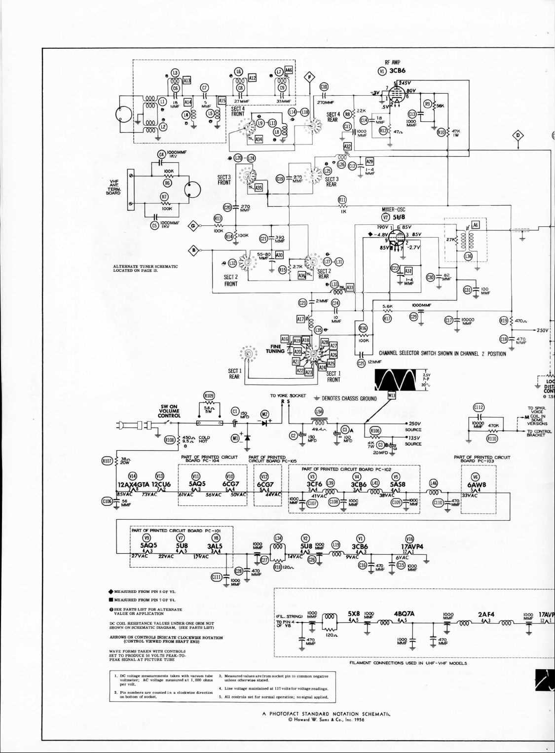
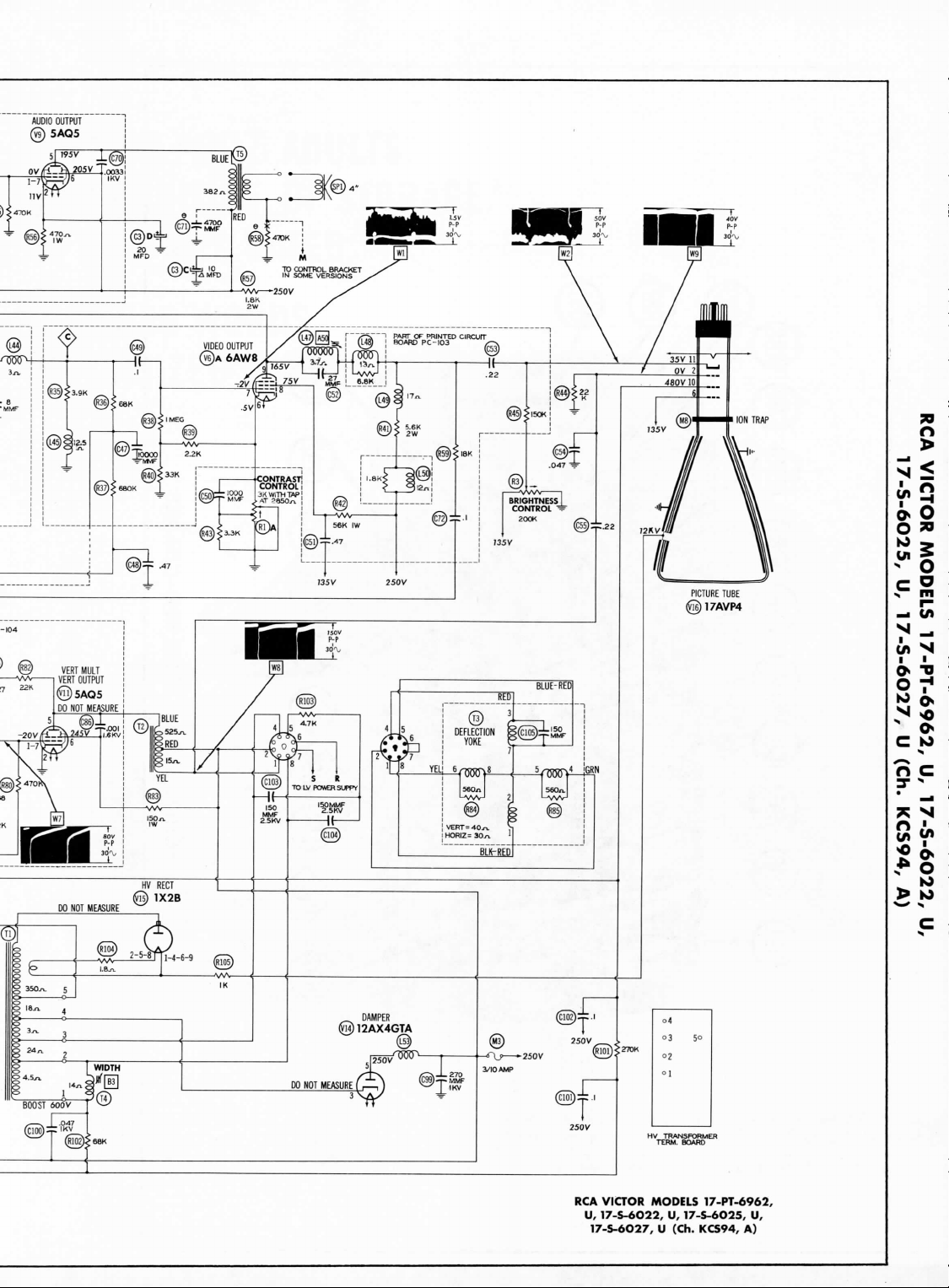
VICTOR MODELS
U,
17-S-6O22,
17-S-6O27, U (Ch.
17-PT-6962,
U,
17-S-6O25,
KCS94,
U,
A)
TUNER
OSCILLATOR
Touch-up
adjustments
circuit
may be
selector
and
tine
PICTURE
To
edge
down
when
PICTURE
For
chassis.
SERVICE
See
SPECIAL ADJUSTMENTS
AGC
If
control until picture shows
stable
TUBE
clean safety
of the
front
and out
bottom
removing safety
TUBE
picture tube removal
(See disassembly
ADJUSTMENT
tube
placement chart
Control Adjustment (Used
receiver overloads
sync.
ADJUSTMENTS
of the VHF
accomplished
tuning
knobs.
SAFETY
glass
remove clamp under
metal trim
of
cabinet).
glass.
REMOVAL
on a
SERVICING
tuner
by
removing
GLASS
CLEANING
and let
safety
Use
extreme caution
it is
necessary
instructions).
LOCATION
on
page
11.
in
VHF-UHF Models only)
strong
signal,
no
sign
of
overloading
oscillator
the
channel
the
bottom
glass
to
remove
adjust
IN THE
slide
the AGC
or un-
FIELD
The
normal setting
position.
HORIZONTAL
The
horizontal hold control (L54)
panel
of the
control.
If
ing
the
horizontal hold,
range
position,
the
horizontal waveform slug
SOUND
IF
To
eliminate sound
detector secondary (A49) located
FUSES
One
fuse
is
(For location
CENTERING
Centering
magnetic
rings
flush
against
around
the
centered.
of the AGC
OSCILLATOR FIELD
chassis
and is
horizontal sync cannot
and
DETECTOR
used
for
see
tube placement
is
accomplished mechanically
around
the
deflection
neck
of the
used
set it at
synchronize
IF
BUZZ
detector
(Bl).
ADJUSTMENT
horizontal sweep circuit protection,
the
neck
yoke.
tube until
control
is at its
ADJUSTMENT
is
located
as a
horizontal hold
be
brought
approximately
the
picture
buzz,
adjust
on top of
chassis.
chart).
by
of the
picture tube, located
Rotate
the two
the
picture
mid-range
on the
control
in by
its
mid-
by
adjusting
the
ratio
adjusting
rings
is
properly
adjust-
two
O
o-
o O
Ji
K>
"The
listing
of any
case a recommendation,
as
to the
parts
have
Inc.,
by the
"Reproduction
G196
available
quality
and
suitability
been
compiled from information
manufacturers
or
use, without
HOWARD
replacement
warranty
of
such
of the
particular
express
or
guaranty
replacement
permission,
W.
SAMS & CO., INC. • Indianapolis
part
herein
does
not
constitute
by
Howard
furnished
type
of
W.
part.
The
to
Howard
replacement
of
editorial
in any
Sams & Co., Inc.,
numbers
of
these
W.
Sams & Co.,
part listed."
or
pictorial
con-
tent,
in any
the
use of the
Sams & Co., Inc., Indianapolis
ternational
Union
(1910)
DATE
5,
Indiana
manner,
is
prohibited.
No
information contained herein. Copyright
Copyright
Union.
by
Howard
patent liability
5,
Indiana,
All
rights
W.
reserved
Sams & Co., Inc." Printed
5-56
U. S. of
America.
under
is
assumed
with
1956
by
Copyright under
Inter-American
in U. S. of
SET
respect
Howard
W.
in-
Copyright
America
315
FOLDER
to
9
Page 2
WON
VOLUME
CONTROL
12AX4GTA
^
MEASURED
•
MEASURED FROM
(JSEE
VALUE
ARROWS
SET TO
PEAK
1.
DC
12CU6
_ZAS
RftRT
OF
PRINTED
CIRCUIT
ra) (w
5AQ5
5U8
FROM
PIN 8 OF V2.
PIN 7 OF V4.
PARTS LIST
FOR
OR
ON
(CONTROL
PRODUCE
SIGNAL
voltage
voltmeter;
per
volt.
ALTERNATE
APPLICATION
CONTROLS INDICATE CLOCKWISE ROTATION
VIEWED FROM SHAFT
50
VOLTS
PEAK-TO-
AT
PICTURE TUBE
measurements
AC
voltage
measured
taken
D
BOARD
3AL5
END)
with
vacuum tube
a t
1,000 ohms
PRINTED
I
PC-104
PC-IOI
3.
unless
CIRCUIT
PART
CIRCUIT
Measured
values
are
otherwise
voltage
stated,
maintained
4.
Line
OF
from
PRINTED
BOARD
s
at
PC-KD5
,F,L.
STRING,
operation;
*
DENOTES CHASSIS GROUND
FART
OF
PRINTED
CIRCUIT
3CF6
3CB6
!$B?
rtJOri 5X8
-r«
^TO
IOOO
1^
MMF
MMF
no
signal
applied.
v
9VAC
RLAMEMT
CHANNEL
12
MMF
BOARD
PC-102
5AS8
J~6VAC
i
470
@
loop
-T-
T
MMF
J^
*•*
4B07A
CONNECTIONS USED
SELECTOR
£l5)
000
MMF
1000
^^
*T*
T" | MMF
IN
SWITCH
UHF-VHF
SHOWN
470
MODELS
IN
2AF4
CHANNEL 2 POSITION
1000
17AVP
PHOTOFACT
©
STANDARD
How.,d
W.
S.m.
NOTATION
* Co,
Inc. 1956
SCHEMATIC
Page 3
@B
AFAMP
SUB
SYNC
A
AMP
6CG7
TAKEN
WITH
TUBE
(VIOB)
AND
HEIGHT CONTROL
CENTER
OF
PIN 7 O
SHORTED
ROTATION.
TO
(R4)
GROUND,
SET AT
Page 4
5 ° !
g
[WID7H
|p
BOOST
. — .
(
«,J%1
600V 1 v
J_
.047
T
@?68K
]
00
NOT
MEASURED
3
TT
®T,™F
3/IOAMP
0101
T'
250V
RCA
VICTOR MODELS
U,
17-S-6O22,
17-S-6O27, U (Ch.
17-PT-6962,
U,
17-S-6O25,
KCS94,
A)
U,
Page 5
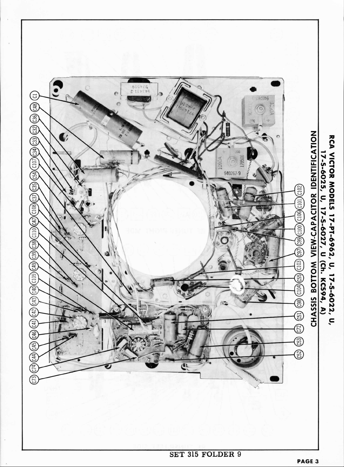
MOIDIA
'SCO9-S-ZL
yn
siaaow
^99)(ciOO)
^97)
(C103)
(C104)(C55)
(C98)
VIEW-CAPACITOR IDENTIFICATION
BOTTOM
CHASSIS
'ZCO9-S-ZI
0
'HD)
yfr6S3>«
(V
yt969-id-/i
7n
'SZO9-S-/L
7n
Page 6
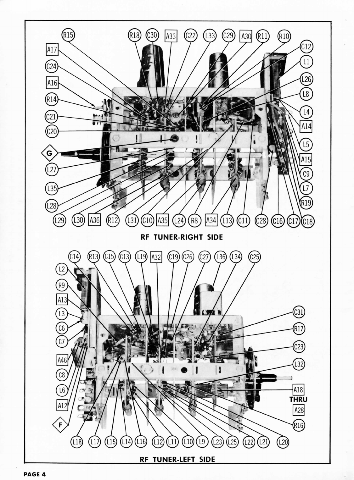
RF
TUNER-RIGHT
SIDE
PAGE
4
RF
TUNER-LEFT SIDE
Page 7
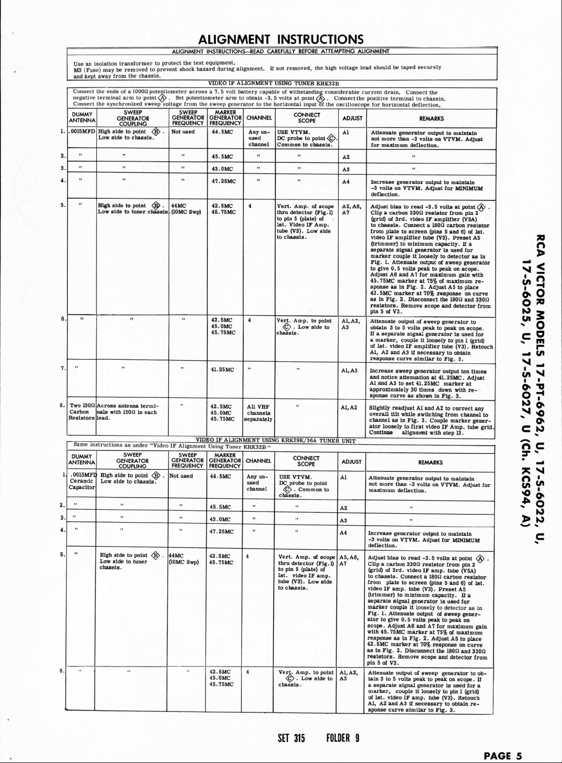
ALIGNMENT
INSTRUCTIONS
ESX^Sttto'l^+SSSiSZ
and
kept
Connect
negative
Connect
DUMMY
ANTENNA
1.
0015MFD
2.
»
3.
"
4.
5.
6
7
Two
130S1
8
Carbon
Resistors
Same
instructions
DUMMY
ANTENNA
1
.0015MFI
Ceramic
Capacitor
2.
3
"
4
5
6
away
from
the
chassis.
the
ends
of a
terminal
the
High
Low
High
Low
Across antenna terminals
lead.
lOOOfi
arm to
synchronized
SWEEP
GENERATOR
COUPLING
side
to
point
side
to
chassis.
"
"
side
to
point
side
to
tuner
with
1,31)12
as
under
SWEEP
GENERATOR
COUPLING
High
side
to
Low
side
to
"
"
High
side
to
Low
side
to
chassis.
point
sweep
in
point
chassis.
point
tuner
potentiometer
^> , Set
vo
tage
GENERATOR
FREQUENCY
Not
<££>
.
<^>
.
44MC
chassis
(10MC
each
"Video
IF
<^
.
Not
^>
.
44MC
across a 7. 5 volt
potentiometer
from
the
SWEEP
used
"
"
Swp)
VIDEO
Alignment
SWEEP
GENERATOR
FREQUENCY
used
"
(10MC
Swp)
augment.
VIDEO
IF
arm to
sweep
generator
MARKER
GENERATOR
FREQUENCY
44 . SMC
45.
SMC
43.0MC
47.25MC
42.
SMC
45.75MC
42 . SMC
45.0MC
45.75MC
41.25MC
42.
SMC
45.0MC
45.75MC
IF
ALIGNMENT
Using
Tuner
MARKER
GENERATOR
FREQUENCY
44.
SMC
45.
SMC
43.0MC
47.25MC
42 . SMC
45.75MC
42.
SMC
45.0MC
45.75MC
If
ALIGNMENT
battery
capable
obtain
-3. 5
to the
CHANNEL
Any
unused
channel
4
4
All
VHF
channels
separately
USING
KRK32B
CHANNEL
Any
unused
channel
-
4
4
not
rented,
USING
of
withstanding
volts
horizontal
USE
VTVM.
DC
probe
Common
Vert.
thru
detector
to pin 5
1st.
Video
tube
(V3).
to
chassis.
Vert.
<g>
chassis.
KRK29K/36A
"
USE
DC
<^> . Common
chassis.
Vert. Amp.
thru
to
pin 5 (plate)
1st.
tube
to
chassis.
Vert.
chassis.
the
TUNER
KRK32B
at
Amp.
Amp.
. Low
probe
video
<g>
considerable
point
<A> . Connect
input
of the
CONNECT
SCOPE
to
point
to
chassis.
"
of
scope
(Fig.l)
(plate)
of
IF
Amp.
Low
side
to
point
side
TUNE!
CONNECT
SCOPE
VTVM.
to
point
»
of
scope
detector (Fig.l)
of
IF
amp.
(V3) . Low
Amp.
to
. Low
side
high
voHage
oscilloscope
<§>.
to
UNIT
to
side
point
to
the
ADJUST
Al
A2
A3
A4
A5.A6,
A7
A1.A2,
A3
A1.A3
A1,A2
ADJUST
Al
A2
A3
A4
A5.A6,
A7
A1.A2,
A3
lead
should
current
dram.
positive
for
horizontal
Attenuate
not
more than
for
maximum
Increase
-3
volts
deflection.
Adjust
Clip a carbon
(grid)
to
chassis.
from
plate
video
(trimmer)
separate
marker
Fig.
1.
to
give
Adjust
45.75MC
sponse
42.
SMC
as in
resistors.
pin
5 of
Attenuate
obtain
If a separate
a
marker, couple
of
1st. video
Al, A2 and A3 if
response curve
Increase
and
notice attenuation
Aland
approximately
sponse curve
Slightly readjust
overall
channel
ator loosely
Continue
Attenuate
not
more than
maximum
Increase generator
-3
volts
deflection.
Adjust
Clip a carbon
(grid)
to
chassis.
from
plate
video
(trimmer)
separate
marker
Fig.
1.
ator
to
scope.
with
45.75MC
response
42.
SMC
as in
resistors.
pin
5 of
Attenuate
tain
3 to 5
a
separate
marker,
of
1st.
Al,
A2 and A3 if
sponse curve
be
taped
securely
Connect the
terminal
to
chassis.
deflection.
REMARKS
generator
output
-3
volts
deflection.
••
"
generator
on
bias
of
IF
couple
Attenuate
0. 5 volts peak
A6 and A7 for
as in
marker
Fig.
V3
3 to 5
A3 to set
tilt
as
on
bias
of
IF
couple
Attenuate
give 0 . 5 volts peak
Adjust
marker
Fig.
V3
video
output
VTVM.
Adjust
to
read
-3 . 5
33012
resistor
3rd.
video
IF
Connect a 180(2
to
screen
amplifier
signal
marker
sweep generator
alignment
3rd.
amp.
signal generator
as
couple
(pins
tube
to
minimum
generator
It
loosely
output
at 75% of
Fig.
2.
Adjust
at 70%
2.
Disconnect
Remove
scope
.
output
of
sweep generator
volts peak
signal generator
it
loosely
IF
amplifier
necessary
similar
41.
25MC
30
times
as
shown
Al and A2 to
while switching
In
Fig.
3.
to
first
video
REMARKS
generator
output
-3
volts
deflection.
output
VTVM.
Adjust
to
read
-3.5
330J2
resistor
video
IF
Connect a 180J2
to
screen (pins
tube
(V3).
to
minimum
it
loosely
output
A6 and A7 for
marker
In
Fig.
2.
at 70%
2.
Disconnect
Remove
scope
.
output
of
sweep generator
volts peak
signal
generator
it
loosely
IF
amp.
necessary
similar
to
on
VTVM.
to
for
volts
from
amplifier
carbon
5 and 6) of
(V3).
capacity.
is
to
detector
of
sweep
to
peak
maximum
maximum
A5 to
response
the
and
to
peak
to pin 1
tube
to
to
Fig.
output
at
41.25MC.
marker
down
in
Fig-
from
Couple
IF
with
step
to
on
VTVM.
to
for
volts
from
amp.
carbon
5 and 6) of
Preset
capacity.
is
to
detector
of
sweep
to
maximum
at 75% of
Adjust
response
the
and
to
peak
is
to pin 1
tube
(V3).
to
to
Fig.
maintain
Adjust
maintain
MINIMUM
at
point
pin 2
(V5A)
resistor
Preset
If a
used
for
generator
on
scope.
gain
place
on
180S2
and
detector
on
scope.
Is
used
(V3).
obtain
3.
ten
Adjust
at
with
re-
3.
correct
channel
marker
Amp.
13.
maintain
Adjust
maintain
MINIMUM
at
point
pin
tube
(V5A)
resistor
A5
If a
used
for
gener-
peak
on
maximum
A5 to
on
180S2
and
detector
on
scope.
used
(grid)
Retouch
obtain
3.
<£>
1st.
A5
as in
with
re-
curve
330ft
from
to
for
(grid)
Retouch
times
any
to
gener-
tube
grid.
for
<^>
2
1st.
as in
gain
place
curve
33012
from
to ob-
If
for
a
re-
.
.
SET
315
FOLDER
9
PAGE
5
Page 8

DUMMY
ANTENNA
.0015MFD
Two
Carbon
Resistors
ceramic
capacitor
Carbon
Resistors
ANTENNA
ANTENNA
High
<^>.
chassis.
Across
13
00
minals
High
10000S2
terminal
Carbon
stal
Resistor
to
in
series
short
with
.0015MFD
TWO
13 on
each
300n
pad
(Fig.
5)
The
antenna matching
in
place.
If a new
alignment
facilities.
affecting
the
connect
point
the
first
video
Connect
the
arm to
obtain
except
in
antenna matching units
adjustment
Connect
the
The
sweep generator
DUMMY
Two
130r
Carbon
Resistor
3 00
ft
Pad
(Fig.
5)
An
RF
unit
This
unit
is
effect
alignment.
When
complete
1.
Turn
2.
Preset
3.
Set
channel 7 thru
4.
Disconnect
resistor.
Tuner
alignment
2
volts
minimum
one
of the
bias supplies
Connect
the
The
sweep generator
DUMMY
Direct
If
channel 8 oscillator
Switch
to
oscillator
back
to
channel
SWEEP
GENERATOR
COUPLING
side
to
point
Low
side
to
VHF
antenna
with
130S2
ead.
side
holder.
tuner
Across
terminals
lead.
Across
terminals
pad
(Fig.
RJT
<1y
IF
negative terminal
-5
for A14 and
synchronized sweep
Across
nals
with
lead.
Across
nals
thru
(Fig.
which
properly aligned
A6 so
A16 all the way
synchronized sweep
RF
input
freq.
insulated
in
hole provided
adjustment
careful
does
not
tuned
may
cause
shift.
channel
frequency
In
to
front
of
IN82
cry-
Low
side
case.
Use
leads.
antenna
(VHF)
with
1300
UHF
antenna
thru
300E2
5).
unit
has
antenna unit
The
FM
alignment. Disconnect
on the
matching
amplifier
tube (V3)
volts
at
point
A15.
output
lead should
SWEEP
GENERATOR
COUPLING
antenna
termi-
13CM2
in
antenna
termi-
300S2
pad
5).
is
operative
alignment
is
that slug
13
the
link
from
as
outlined
and 5. 5
volts
to
point
output
SWEEP
GENERATOR
COUPLING
of
heterodyne
meter
to end of
wire
insertec
for
of
A30.
that
the
wire
touch
any of the
circuits
as
this
oscillator
frequency cannot
12 and
adjust
on
each
8 and
again adjust
VIDEO
IF
SWEEP
GENERATOR
FREQUENCY
44 MC
(10MC
Swp)
ter-
each
797MC
(10
MC
Swp)
very
44 MC
in
(10MC
Swp)
See
freq.
chart
of
all UHF
channels
been properly aligned
is
trap adjustment
of
<£>
C8
would
vo
each
and
at the
necessary
is all the way
out.
slugs
terminals
below requires
max mum
<^ . Positive
lead
Be
A18
channel.
KRK32B,
installed,
the RF
the
lead
unit
through
from
its
potentiometer
on
VTVM.
in
which
C6, C7 and C8 are
be
adjustment A12.
tage
from
be
terminated
SWEEP
GENERATOR
FREQUENCY
Not
used
50 MC
(20MC
Swp)
requires
only
factory
and
make
out.
one
turn
from
of
measured
vo
tage
from
should
be
termi
SWEEP
GENERATOR
FREQUENCY
Not
used
be
reached
for
channel
Also
A16.
Note:
the use of a
ALIGNMENT
MARKER
GENERATOR
FREQUENCY
41.25MC
42 . SMC
45.0MC
45.75MC
45.75MC
42.5MC
42.5MC
45.0MC
45.75MC
46.
SMC
KRK29K/36A
at the
unit
should
(A46)
which
from
the FM
a .
001MFD
socket.
Cover
arm of
bias
Adjustments
the
sweep
generator
with
MARKER
GENERATOR
FREQUENCY
45.75MC
(4
00
".Mod)
41.25MC
(4000-Mod)
50 MC
52MC
53 MC
60MC
minor
touch
under norma
the
following
tight.
converter
plate transformer (L36)
at
point
side
to
tuner
the
sweep generator
ated
with
MARKER
GENERATOR
FREQUENCY
Set
freq.
meter
227MC
by
adjustment
12
oscillator
on
channel 8 adjust
USING
KRK29K/36A
CHANNEL
4
All VHF
channels
separately
Between
channels
68
and 69
Check
all
VHF
channels
Check
aUUHF
channels
ANTENNA
factory.
The RF
be
realigned.
is
located
on the
trap (L7)
capacitor
to pin
o the
matching
supply
to
point
A!2
variable
capacitors.
to the
its
characteristic impedance, usually
CHANNEL
Any
up
adjustments will require
use
should
pre -
adjustments.
heterodyne
to
frequency
<^>
with a VTVM.
chassis.
to the
its
characteristic
CHANNEL
8
of
frequency. Continue
A16 for
TUNER
CONNECT
SCOPE
Vert.
Amp.
<g>.
Low
chassis.
Vert.
Amp.
detector
{Fig.
junction
of
.0015MFD
remarks).
to
chassis.
Vert.
Amp.
detector
point
<$>
side
to
chassis.
Vert.
Amp.
point
<£>
side
to
chassis.
WATCHING
unit
is
Alignment
antenna
to the
channel
(grid)
of
unit
must
0*0 . Positive
thru
A15
are
adjusted
C6
horizontal input
CONNECT
SCOPE
Vert.
Amp.
point
<£>
side
to
chassis.
Vert- Amp.
detector
1)
to
point
Low
side
KRK32B
TUNER
not
require
and
meter.
Connect
Adjust
for -3. 5
horizontal
impedance,
CONNECT
SCOPE
Not
used
A16, switch
to
to
channel 8 oscillator
UNIT
to
point
side
to
thru
1) to
220S2
and
(see
Low
side
thru
(Fig.
1) to
. Low
to
. Low
UNIT
aligned
with a particular
should
matching unit
selector
second video
be in
place
termina
by
would
be
of the
to
. Low
thru
probe (Fig.
<£>
.
to
chassis.
ALIGNMENT
no
presetting
alignment
shunt
the
terminals
The
limits
negative
volts
bias
input
of the
usually
channel
13 and
channel
8.
frequency.
(CONT.)
ADJUST
Increase
A1.A3
and
Al
and A3 to set
approximately
curve
SLIGHTLY
A1.A2
any
channel
Set
A8,A9
n
series
(ceramic)
ar.d
to
pin 1 of
If
VHF
couple
a
second
side
point
0. 5
and
Tuner
A10,
All
marker
If
necessary,
place
with
and
4BQ7A
from
A1,A2
Couple
video
curve
SLIGHTLY
to
correct
Couple
A10.AU
video
curve
channels.
A10
Do
A9
attempted
may be
adjusted
Use a
IF
amplifier tube
during
alignment.
to
chassis.
or
compressing coil turns,
A13.
for
50
ohms.
ADJUST
A12
A13
A14.A15
of
adjustments.
of L36
of
oscillator
of
at
point
<^>
for
50
ohms.
ADJUST
A16
adjust
A17 for
proper
Switch
Disconnect both
antenna
short
Set the
Set
MINIMUM
Remove
chassis.
sponse
steps
ment
and the
and
potentiometer
Turn fine tuning
position.
frequency
oscillator
ALIGNMENT
not be
switch.
expanding
adjustment
oscilloscope
unless components
termina
oscilloscope
Adjust
REMARKS
sweep
notice
overall
tuner
chassis
volts
A9 for
not
in
<£>
with a 3
injection
to
generator
attenuation
as
shown
to VHF
to UHF
with a .0015MFD
between
4BQ7A
generator
it
loosely
bias
to
tuner
<D> . Attenuate
peak
maximum gain
in UHF
generator
45.75MC
MINIMUM
.0015MFD
tube. Remove
point
marker
IF
amplifier
similar
marker
IF
amplifier
similar
If
and All to
retouch
this
step.
matching
without
without
jumper
(V4).
C7
would
horizontal deflection,
scope
gain
the
to pin 1
Adjust
curve
13, 14 and 15
is
noted.
detector probe between point
chassis.
are
changed
horizontal deflection.
Adjust
meter.
channel
channel
at
41.25MC.
41.25MC
30
times
down with
in
Fig.
3.
readjust
Al and A2 to
tilt
while switching
channel (Fig.
position.
pin 1
with
<$>
retouch
for any
potentiometer
400^
.001MFD
9S2
trimmer
(plate)
the
capacitor
and
resistor
is
used
to
detector
supply
to
point
case.
Adjust
sweep
to
peak
on
position-
Loosely
to
detector
adjust
A10 and
marker
at
tilt.
Remove
capacitor
detector
.
generator
grid.
to
Fig.
3 on all VHF
Al and A2 if
overall
generator
grid.
to
Fig.
3 on ail UHF
necessary,
SLIGHTLY retouch
correct
for any
Al, A2, A3, A6, A7, A8 or
Remove
bias
supplies.
unit
the
proper
seriously
to
Remove
be
REMARKS
to
maximum
indication
capacitor
of
V4.
Connect a 30012,
A14 and A15 to
similar
to
until
no
Remove
the
Replace
V3 in its
to
carbon
voltage
are
arm of
REMARKS
control
A16 for
audible beat
13
oscillator
to
13 and
adjust A17, then
output
ten
times
Adjust
marker
at
response
correct
from
VHF
3).
Connect a 220fi
capacitor
of
4BQ7A
end
connected
end to
as a
marker,
(Fig-1).
Connect
<@> . Positive
for -3
volts
generator
scope.
Adjust
as in
Fig.
4.
couple
(Ftg.l).
AH
to
peak
of
curve
220J2
resistor
from
pin 1 of
and
scope
loosely
to
Check
for
response
channels.
necessary
tilt
as in
loosely
to
Check
for
response
overall
all
test
equipment.
and
adjust
on
scope.
from
obtain
Fig.
6.
Repeat
further improve-
300S2
resistor
socket.
to its
mid-range
frequency.
obtain
chassis
at
for
A8
first
step
first
tilt.
for
point
\n
re-
<£>
on
ALIGNMENT
8.
resistor
from point
SCOPE
OR
VTVM
F
F
IG.4
TO
IG.2
F
IG.
INST
—pMMF
T
FIG.
<£>
to
8
I
300
R
PAGE
6
Page 9

ER
UNIT
(CONT.)
CT
E
A1,A3
to
point
e to
A1,A2
A8.A9
thru
IB-
i)
to
220ft
and
see
Low
side
.
thru
'ig.l)
to
Low
ssis.
. to
Low
ssis.
ING
UNIT
ALIGNMENT
gned
with a particular
nt
should
not be
itching
unit
selector
switch.
icond
video
t
be in
place
ive
terminal
asted
by
expanding
would
be
adjustment
ut
of the
oscilloscope
e,
usually
50
. to
Low
ssls.
.
thru
•obe
(Fig.
re no
presetting
ignment
unless
.unt
the
terminals
The
limits
t
negative
terminal
volts
bias
at
nit
of the
oscilloscope
:e.
usually
50
ECT
PE
lannel
13 and
mimel
8.
Adjust
illator frequency.
ADJUST
Increase
and
Al
approximately
curve
SLIGHTLY
any
channel
Set
in
(ceramic) between
and
to
If
couple
a
side
point
0. 5
and
A10,
All
Tuner
marker
If
place
with
and
4BQ7A
from
A1.A2
Couple
video
curve
SLIGHTLY
to
A10,A11
Couple
video
curve
channels.
A10
Do
A9
Disconnect
antenna
attempted
may be
adjusted
Use a
IF
amplifier
during
alignment,
to
chassis.
or
compressing coil turns,
A13.
for
ohms.
Set
MINIMUM
A14,A15
Remove
chassis.
sponse curve
steps
ment
and the
and
of
adjustments.
components
of L36
of
oscillator
of
potentiometer
point
<§>
.
for
ohms.
ADJUST
Turn
position.
frequency
adjust
A17 for
proper
Switch
sweep
notice
and A3 to set 41.
overall
tuner
series
chassis
pin 1 of
VHF
second
A9 for
necessary,
correct
not
In
short jumper
tube
Set the
C7
horizontal
<T>
with a 39i2
injection
oscillator
to
generator
attenuation
30
as
shown
in
readjust
tilt
while switching
to VHF
channel (Fig.
to UHF
position. Connect a 220S2
with a .0015MFD
with
the
4BQ7A
and
generator
it
loosely
to
bias
supply
to
tuner
case.
<S> . Attenuate sweep
vous
peak
to
peak
maximum gain
in UHF
position.
generator
adjust
45.75MC
marker
MINIMUM
tilt.
.0015MFD
capacitor
tube.
Remove
point
<£>
.
marker
generator
IF
amplifier
similar
to
retouch
for any
marker
generator
IF
amplifier
similar
to
If
necessary,
and All to
correct
retouch
Al, A2, A3, A6,
this
step.
Remove
both
bias
matching
without
the
proper
without
seriously
to
(V4). Remove
potentiometer
would
be
deflection,
scope gain
to
400",
indication
the
.001MFD
to pin 1 of V4.
Adjust
A14 and A15 to
similar
13, 14 and 15
is
noted.
Remove
detector
are
changed
fine
tuning
Adjust
meter.
channel
channel
probe between
Replace
carbon
voltage
arm of
deflection.
control
A16 for
13
oscillator
trimmer
13 and
chassis.
horizontal
REMARKS
output
at
41.25MC.
25MC
marker
times
down
Fig.
3.
Al and A2 to
capacitor
pin 1
(plate)
capacitor
resistor
Is
used
as a
detector
to
point
Adjust
for
on
scope.
as in
Loosely couple
to
detector
AID
and All to
at
peak
Remove
from
detector
loosely
grid.
Check
Fig.
3 on all VHF
Aland
A2 if
overall
loosely
grid.
Check
Fig.
3 on
SLIGHTLY retouch
for any
all
supplies.
unit
maximum
on
capacitor
Connect a 300S3,
to
Fig.
until
no
the
V3 in its
to
are
REMARKS
to Its
audible beat
frequency,
to
obtain
adjust
ten
times
Adjust
at
with
response
correct
from
VHF
3).
of
4BQ7A
end
connected
end to
chassis
marker,
(Fig.l).
Connect
<fj> . Positive
-3
volts
generator
Adjust
Fig.
4.
(Fig.l).
of
curve
220ii
resistor
pin 1 of
and
scope
to
first
for
response
channels.
necessary
tilt
as in
step
to
first
for
response
all
UHF
overall
AT,
A8 or
test
equipment.
and
adjust
scope.
from point
obtain
6.
Repeat
further
improve-
300Q
resistor
point
<£>
socket.
mid-range
on
A17,
then
ALIGNMENT
at
for
A8
8.
tilt.
for
\t carbon
re-
SCOPE
VTVM
F
F
IG.4
52
f\
TO
OR
IG.2
1—t-
FIG.6
F
INSTRUCTIONS
—"—
IOO
—pMMF
FIG.
I
300
53 60
resistor
from
point
IG.
8
IN
34
PAD
OF
^.BALANCED
INPUT
<^>
to
.005
47.
MFD
F
IG.3
FIG.
5
F
IG.7
FIG.9
(cont)
DUMMY
ANTENNA
Two
18
Carbon
Resistors
19
Two
20
Carbon
Resistors
21.
Connect
channels 8 thru
II
i2
Two
23
Carbon
Resistors
24
TwolSOf
25
Carbon
Resistors
_D
26
27
28.
|
Same
DUMMY
ANTENNA
29.
Direct
30
Note:
31.
frequency.
trimmer
13
130S;
Across
nals
lead.
Connect
meter
130S
Across
nals
lead.
the DC
either
is
replaced,
Connect
meter
Across
130!:
nals
lead.
Connect
meter
Across
nals
lead.
Connect
meter
instructions
High
Low
RF
frequency
of
serted
for
Be
does
the
this
lator
If
channel 8 oscillator
Switch
to
obtain
and
adjust A17,
SWEEP
GENERATOR
COUPLING
antenna
with
130S2
frequency
as in
antenna
with
130ft
probe
13
if
voltage
repeat
frequency
as in
antenna
with
130ft
frequency
as in
antenna
with
13017
frequency
as in
as
SWEEP
GENERATOR
COUPLING
side
to
side
to
input
of
meter
insulated
in
hole provided
adjustment
careful that
not
touch
tuned
circuits
may
cause
shilt.
oscillator
then
termi-
in
step
16.
termi-
in
of a
VTVM
step
termi-
in
step
termi-
in
step
under
point
chassis.
heterodyne
to end
wire
of
wire
any of
oscil-
to
channel
back
each
each
to
is not
oscillator
16.
each
16.
each
16.
"KRK32B
<g>
.
In-
A30.
as
frequency
12 and
frequency
to
channel
SWEEP
GENERATOR
FREQUENCY
183MC
(10MC Swp)
Not
used
213MC
(10MC
Swp)
point
<G> . Common
within
limits.
tracking procedure
Not
used
183
MC
(10MC
Swp)
Not
used
85MC
(10MC
Swp)
85MC
(10MC
Swp)
79MC
(10MC
Swp)
69MC
(10MC
Swp)
63 MC
(10MC
Swp)
57MC
(10MC
Swp)
213MC
(10MC
Swp)
207MC
(10MC
Swp)
201MC
(10MC
Swp)
195MC
(10MC
Swp)
189MC
(10MC
Swp)
183MC
(10MC
Swp)
H7MC
(10MC
Swp)
Not
used
Tuner
Alignment".
SWEEP
GENERATOR
FREQUENCY
Not
used
cannot
be
adjust
on
each channel.
8 and
again adjust A39.
MARKER
GENERATOR
FREQUENCY
181.25MC
185.75MC
Freq.
meter
257MC
211.25MC
215.75MC
Check
Freq.
meter
227MC
181.25MC
I85.75MC
Freq.
meter
129MC
83. 2 SMC
87.75MC
83.25MC
87.75MC
77.25MC
81.75MC
67.25MC
71.75MC
61.25MC
65.75MC
55.25MC
59.75MC
211.25MC
215.75MC
205.25MC
209.75MC
199. 2 SMC
203.75MC
193.25MC
197.75MC
187.25MC
191.75MC
181.25MC
185.75MC
175.25MC
179.75MC
Freq.
meter
257MC
251MC
245MC
239MC
233MC
227MC
221MC
129MC
123 MC
113 MC
107MC
101MC
MARKER
GENERATOR
FREQUENCY
43 . SMC
(400^Mod)
Set
freq.
meter
227MC
reached
A18 for
to
to
chassi
V2 by rep
for
to
to
to
to
by
adjust
chanm
Also,
chaj
on c
CH
CH,
8
13
8
6
5
4
J
'i
13
12
11
10
9
8
V
13
12
11
ID
9
|
7
6
5
4
3
2
2
8
Page 10

TRUCTIONS
IN34
-OO5MED
•IOOK
>
IOK
F
IG.3
FIG.5
F
IG.7
F
IG.9
(cont)
3
VR.
^\.
450\5
^"
/
/
/V-0
300
BALANCED
OUTPUT
A
26
N>.
27'
/IDE\.
-5.75\
29
\
23
^
DUMMY
ANTENNA
Two 13
Carbon
Resistors
19
20
Two
Carbon
Resistors
Connect
channels 8 thru
If
either
Two
Carbon
Resistors
24
TwolSOS
2
=
Carbon
Resistors
Same
DUMMY
ANTENNA
Direct
30
Note:
31.
frequency.
trimmer
13
and
Of
Across antenna
nals
with
lead.
Connect
meter
130!
Across
nals
with
lead.
the DC
probe
13 if
is
replaced,
Connect
meter
Across
130f,
nals
with
lead.
Connect
meter
Across antenna
nals
with
lead.
Connect
meter
instructions
High
side
Low
side
RF
input
frequency
of
insulated wire
serted
for
adjustment
Be
careful
does
not
the
tuned
this
may
lator
shilt.
If
channel 8 oscillator
Switch
to
obtain
adjust
AIT,
SWEEP
GENERATOR
COUPLING
termi-
130S2
in
frequency
as in
step
antenna
termi-
I30ft
in
of a
VTVM
voltage
repeat
frequency
as
in
step
antenna termi-
I30H
in
frequency
as in
step
130S2
in
frequency
as in
step
as
under
SWEEP
GENERATOR
COUPLING
to
point
to
chassis.
of
heterodyne
meter
in
hole
provided
of
that
wire
touch
any of
circuits
cause
oscil-
to
channel
oscillator
then
back
each
16.
each
to
is not
oscillator
16.
each
16.
termi-
each
16.
"KRK32B
<^>
.
to end
In-
A30.
as
frequency
frequency
to
channel
SWEEP
GENERATOR
FREQUENCY
183MC
(10MC
Swp)
Not
used
213MC
(10MC
Swp)
point
<G> . Common
within
limits.
tracking
Not
used
183
MC
(10MC
Swp)
Not
used
85MC
(10MC
Swp)
85MC
(10MC
Swp)
79MC
(10MC
Swp)
69MC
(10MC
Swp)
63MC
(10MC
Swp)
57MC
(10MC
Swp)
213 MC
(10MC
Swp)
20TMC
(10MC
Swp)
201MC
(10MC
Swp)
195MC
(10MC
Swp)
189MC
(10MC
Swp)
183 MC
(10MC
Swp)
1TTMC
(10MC
Swp)
Not
used
Tuner
Alignment".
SWEEP
GENERATOR
FREQUENCY
^ot
used
cannot
12
and
adjust
on
each channel. Also,
8 and
again adjust A39.
GENERATOR
FREQUENCY
181.25MC
185.T5MC
Freq.
meter
257MC
211.25MC
215.75MC
Check
procedure
83.25MC
87.75MC
77.25MC
81.75MC
67.25MC
71.75MC
61.25MC
65.75MC
55.25MC
59.75MC
211.25MC
215.75MC
205.25MC
209.75MC
203.75MC
193.25MC
197.75MC
Freq.
meter
257MC
251MC
245MC
239MC
233MC
227MC
221MC
129MC
123MC
113MC
107MC
101MC
GENERATOR
FREQUENCY
43.
(4001Mod)
Set
meter
227MC
be
reached
KRK32B
MARKER
to
to
V2 by
Freq.
meter
to
227MC
181.25MC
185.75MC
Freq.
meter
to
129MC
83.25MC
87.75MC
199.25MC
187.25MC
191.75MC
18I.25MC
185.75MC
1T5.25MC
179.75MC
to
MARKER
SMC
freq.
to
by
A18 for
TUNER
CHANNEL
a
13
chassis.
replacing
for
channels 8 thru
8
6
5
4
3
2
13
12
11
10
9
8
7
13
12
11
10
9
8
7
6
5
4
3
2
KHK29K/36A
CHANNEL
2
8
adjustment
channel
on
channel 8 adjust
ALIGNMENT
Check
5U8
VHF
of
12
oscillator
CONNECT
SCOPE
Vert. Amp.
point
<§>
side
to
chassis.
Not
used
Vert, Amp.
point
<§>
to
chassis.
oscillator
tube.
If
13.
Not
used
Vert.
Amp.
point
<Q>
side
to
chassis.
Not
used
Vert. Amp.
point
<§>
side
to
chassis
Not
used
TUNER
CONNECT
SCOPE
Vert. Amp.
<B>
• Low
chassis.
Not
used
A39, switch
frequency.
A39 for
(CONT.)
ADJUST
to
. Low
. Low
injection voltage-
voltage
. Low
. Low
A29,
A30,
A31
A17
A32,
to
A33
side
is
still
A16
A29,
to
A30,
A31
A24
A34,
to
A35,
.
A36
A17
A18
A19
A20
A21
A22
A23
A24
A25
A26
A27
A28
ALIGNMENT
ADJUST
A37
to
point
side
to
A38,A39
A16
to
channel
13 and
Continue
channel 8 oscillator
Set
scope
indication
A31
for
A29
affects
A30
affects
Turn
position.
A17
an
and
readjust
beat.
Adjust
4.
Check
oscillator
off,
replace
oscillator
Check
If
necessary,
frequency.
If
necessary
obtain
quired
switch
lator
necessary
until proper
Set
fine
position.
frequency
Adjust
Check
A34
affects
midway
freq.
A34
has
Check
Check
channel
80%
on any one
and A36 to
proper
Check
Check
channel
80%
on any one
and
A31 to
proper
Adjust
for
audible beat
oscillator
at
point
within
volts maximum.
Short
scope
MINIMUM
necessary
field
to
specific
A37
is not
that channel's sensitivity.
from
tuner
Preset
Turn
Adjust
Adjust
meter.
until
beat
turn
one
turn
fine
position.
adjust
AIT
to
channel
frequency.
REMARKS
to
maximum
on
scope.
response
curve
bandpass.
the
overall
fine
tuning
control
Adjust
A17 for
additional turn
A16 to
for
proper
response
tracking
coupling
for
audible
beat
adjust
retouch
response
as in
adjustment, turn
back
to
channel
Injection
voltage
repeat
steps
response
tuning control
Adjust
A24 for
meter.
for
response
oscillator
injection
maximum
between
markers.
bandpass.
A36
been properly
for
response
oscillator
injection
at
point
^> . 11
channel,
obtain
response
limits.
for
response
oscillator
injection
at
point
<§> . 11
channel, retouch
obtain
response
limits.
individual channel
on
each channel.
Injection
voltage
<G>
to
verify
limits, 2 volts
REMARKS
out
tuner
AGC at
for
maximum
40(K
indication
A37 may be
provide additional
frequency.
A38
fine
bias
A39 for
Adjust
for
8.
Exercise
tuned
into channel 2 reducing
AGC
at
point
to
read
-3
tuning control
to
read
audible beat
AI6
note
just
begins
full
turn
in
tuning control
channel
13
Adjust
proper
Switch
gain
for
usable
Adjust
A20,
similar
to
A31
affects
response
to
Its
mid-range
audible
In
the
same
again
obtain
as
shown
on
capacitor
on
frequency meter
A16 for
proper
A29,
A30 and A31 to
Fig.
4. If A31 re-
off
generator
13 and
check
as in
step
20, 21 and 22
is
obtained.
to its
mid-range
audible
curve
similar
as
In
amplitude
A35
affects
tilt
adjusted)
similar
to
Fig.
voltages
markers
retouch A34,
curves
similar
to
Fig.
voltages
markers
curves within
oscillator
on
each
that
the
voltages
MINIMUM
point
<^> . Adjust
gain.
Adjust
on
scope.
adjusted
in the
rejection
care
Remove
<D>
.
volts
at
point
fully
clockwise.
-4
volts
at
point
on
frequency
clockwise
to
change, then
same direction.
to
its
mid-range
oscillator
oscillator
back
to
channel
A30 and
Fig.
4.
the
tilt.
bandwidth.
beat.
Turn
direction
an
audible
in
(C23)
.
and
oscil-
21. il
beat
on
to
Fig.
step
24.
of
curve
affects
(providing
.
7.
for
each
fall
below
A35
within
7.
for
each
fall below
A29,
A30
slug
Recheck
channel
are
and 5. 5
A37 for
If
of a
so
that
short
<§>
<§>
Re-
Fig.
7.
.
.
PAGE
7
Page 11

32
33.
34.
35
36
37
38
39
40
41
42
43
DUMMY
ANTENNA
TwolSOn
Carbon
Resistors
Connect
the DC
Two
130!!
Carbon
Resistors
Two
1301
Carbon
Resistors
TwolSOn
Carbon
Resistors
If
A38
required adjustment,
proper
oscillator
Two
130!i
Carbon
Resistors
SWEEP
GENERATOR
COUPLING
Across
antenna
130S!
probe
frequency
step
VHF
with
frequency
step
30.
VHF
with
Frequency
as in
with
frequency
with
130!!
as in
termi-
in
of a
VTVM
30.
antenna ter-
300£!
antenna ter-
13012
step
130S2
in
termi-
in
step
each
meter
in
meter
in
30.
each
switch
as in
each
30.
nals
with
lead.
Connect
as
In
Across
minals
lead.
Connect
as in
Across
minals
lead.
Connect
meter
Across antenna terminals
lead.
Across antenna
nals
lead.
Connect frequency
meter
each
each
ALIGNMENT
SWEEP
GENERATOR
FREQUENCY
183MC
(10MC
Swp)
to
point
<G> . Common
Not
used
213MC
(10MC
Swp)
Not
used
183MC
(10MC
Swp)
Not
used
85MC
(10MC
Swp)
receiver
and
step
30.
85MC
(10MC
Swp)
79MC
(10MC
Swp)
69MC
(10MC
Swp)
63
MC
(10MC
Swp)
57MC
(10MC
Swp)
213MC
(10MC
Swp)
207MC
(10MC
Swp)
201MC
(10MC
Swp)
195MC
(10MC
Swp)
189MC
(10MC
Swp)
183MC
(10MC
Swp)
177MC
(10MC
Swp)
Not
used
KRK29K/36A
MARKER
GENERATOR
FREQUENCY
181.25MC
185.75MC
to
Freq.
meter
257MC
211.25MC
215.75MC
Freq.
meter
227MC
181.25MC
185.75MC
Freq.
meter
to
129MC
83 . 25MC
87.75MC
generator
83.25MC
87.75MC
77.25MC
81.75MC
67.25MC
71. 7 SMC
61.25MC
65.75MC
55.25MC
59.75MC
211.25MC
215.75MC
205.25MC
209.75MC
199.25MC
203.75MC
193.25MC
197. 7 SMC
187.25MC
191.75MC
181. 2 SMC
185.75MC
175.25MC
179.75MC
Freq.
meter
257MC
251MC
245MC
239MC
233MC
227MC
221MC
129MC
123MC
113
MC
107MC
101MC
INSTRUCTIONS
VHF
TUNER
ALIGNMENT
CHANNEL
chassis.
to
to
to
channel
to
8
13
13
8
6
6
5
4
3
2
13
12
11
10
9
Adjust
8
7
13
12
11
10
9
8
7
6
5
4
3
2
8.
Readjust
Vert.
point
side
A38 for
Not
Vert.
chassis.
Not
Vert. Amp.
<g>
chassis.
Not
Vert. Amp.
to
chassis.
Vert. Amp.
point
side
Not
CONNECT
SCOPE
Amp.
to
<§>
. Low
to
chassis.
negative 3 volts
used
Amp.
<§>
. Low
side
used
. Low
side
used
to
<@> . Low
A31 for
to
<§>
. Low
to
chassis.
used
(CONT.)
to
point
to
to
point
to
point
side
response
(cont)
ADJUST
A29,
A30,
A31,
A40
at
poin
A17
A32,
A33
A16
A29,
A30,
A31,
A40
A24
A34.A35,
A36
similar
A17
A18
A19
A20
A21
A22
A23
A24
A25
A26
A27
A28
REMARKS
Set A6
fully counter
gain
to
maximum
output
produce
for
response
for
maximum
A29
affects
A40
is
response bandwidth.
<g> • Repeat steps
Rotate
clockwise . Adjust
audible beat
overshoot
turn
in the
A16
to
Adjust
Fig.
4.
oscillator
as in
step
turn sweep generator back
channel
A32
and A33 for
Check
If
necessary
tor
frequency.
If
necessary
A40
to
If
A31
generator
check
oscillator
step
33. If
and
37
Set
fine tuning
position.
frequency
Adjust
for
Check
oscillator
step
33.
to
Fig.
4.
Check
for
Check
oscillator
channel
80%
on any one
A36
to
obtain
limits
.
Check
for
Check
oscillator
each channel
below
80% on any one
A30
and A31 to
within
proper
Adjust
for
audible beat
oscillator
at
point
within
limits 2 volts
volts
maximum.
and
for
minimum
usable
pattern
similar
amplitude
bandpass.
properly
adjusted) . A30
fine
again
for
for
obtain response
required
individual
31 and
tuning
control
A17 for
on
ireq.
the
adjustment
same direction, then adjust
obtain
an
proper response
Turn
off
generator
voltage
at
33 . If A38
13
response.
desired
audible beat
adjust
A16 for
retouch A29, A30,
adjustment,
and
switch
injection voltage
necessary,
until proper
Readjust
at
<§>
response
control
Adjust
A24 for
meter.
response curve
injection
A38 if
Recheck
A16 and A39 for
response
similar
injection
point
<Q>
. If
channel, retouch
response
response curve
InjecUon
at
point
obtain
limits
.
channel
on
each channel.
injection
voltage
to
verify
clockwise . Set
attenuate generator
input
on
to
Fig.
between
A31
32.
meter.
audible
point
required
If
necessary,
response.
on
similar
to
channel
repeat
to its
audible beat
necessary.
voltage
markers fall
curves within proper
voltages
<u>
. If
cnannel
response
that
MINIMUM
signal
scope.
4.
Adjust
affects
maximum
maximum
SLIGHTLY
an
additional
beat.
as
shown
and
check
<§>
using
readjustment
on and
frequency
proper
A31 and
to
turn
13 and
steps
is
obtained.
mid-range
similar
voltage
to
Fig.
A3 5 and
similar
markers
retouch
curves
oscillator
on
each channel
the
voltages
and
scope
that will
Adjust
markers.
tilt
affects
VTVM
recheck
retouch
meter.
oscilla-
Fig.
off
as in
35, 36
on
to
as in
7.
for
to
Fig.
for
slug
Recheck
5.5
A40
(when
the
in
4.
Fig.
each
below
fall
A29,
are
7.
7.
PAGE
8
Page 12

Turn
the
To
make
may be
aligned
It
will
be
Reference
between
Connect
DUMMY
ANTENNA
44.
300IJ
pad
(Fig.
5)
45.
Repeat
steps
46
the
response curve.
of
the RF
tuning
in the
touching
47.
Connect
the DC
between
.03 and .35
or an
oscillator
to
chassis.
cases
replacement
bands
is
Tune
in a
Ground
pin 2
DUMMY
ANTENNA
48.
.01MFD
49
50.
Ground
pin 2
DUMMY
ANTENNA
51.
.01MFD
Channel t requency
2
54-60
3
bO-66
4
66-72
5
76-82
7
174-180
8
180-186
9
186-192
0
192-198
1
198-204
2
204-210
3
210-216
4
470-476
5
476-482
6
482-488
7
488-494
8
494-500
9
500-506
1
512-518
2
518-524
change
over
the RF
adjustments
without
necessary
marks
the
stop
pin
the
synchronized
GENERATOR
Across
UHF
terminals
pad
(Fig.
44 and 45
plates
is
lower
the
plates
probe
tube
VTVM
required
as
local
TV
(grid)
GENERATOR
High
side
of
video
Low
side
(grid)
GENERATOR
High
side
of
video
Low
side
Video
55.25
61.25
67.25
77.25
175.25
181-25
187.25
193-25
199.25
205.25
211.25
471.25
477.25
483.25
489-25
495.25
501.25
513.25
515.25
switch
to UHF
for UHF
removing
to
fabricate a test
at 0°, 5° and
on'
the
tuner
sweep
SWEEP
COUPLING
antenna
thru
300S2
5).
until response curves
They
may
necessary
frequency
with
should read
of the
station
of 3rd
SIGNAL
COUPLING
to pin 7
output
to
ride
to
to
the
knifing
of a
VTVM
volts should
operating outside
.5
oscillator
outlined
above
in
which
video
(grid)
tube
(V6A)
chassis.
"
of 3rd
video
SIGNAL
COUPLING
to pin 7
(grid)
output
tube
chassis.
Sound
59.75
65.75
71.75
81.75
179.75
185.75
191.75
197.75
203.75
209.75
215.75
475.75
481.75
487.75
493.75
499.75
505.75
517.75
523.75
(V6A
to
ALIGNMENT
position.
tuner,
UHF
164°
and the
voltage
correct
avoid
to
be
IF
the UHF
tuner.
dial
to fit
should
GENERATOR
FREQUENCY
down
tool while observing
point
obtained. Voltages outside these limits
and
tube
.
interference
amplifier
GENERATOR
FREQUENCY
.
(Unmod)
over
be
scribed
stop plate
from
the
SWEEP
887.
5MC
(20MC
Swp)
473 . 5MC
(20MC
Swp)
as in
the
curve
tracking.
affecting
the
ffl> .
Common
its
allowable
2.5
volts. Readings outside
should
follow.
is
tube
SIGNAL
4.
SMC
"
IF
amplifier
tube
SIGNAL
GENERATOR
FREQUENCY
4.5MC
(Unmod)
TELEVISION
Channel
frequency
23
524-530
24
530-536
25
536-542
26
542-548
28
554-560
29
560-566
30
566-572
32
578-584
33
584-590
34
590-596
35
596-602
36
602-608
37
608-614
38
614-620
39
620-626
40
626-632
42
618-644
43
644-650
KRK29K/36A
tuner
unit
the
split gear
on the
test
on the
gear assembly
sweep generator
MARKER
GENERATOR
FREQUENCY
887.
SMC
41.25MC
43.
SMC
45.75MC
473.
SMC
41.25MC
43.
SMC
45.75MC
Fig.
8 and
necessary
the
to
limits.
If the
to
CHANNEL
Fig.
response.
chassis.
Connect
oscillator
Adjust
chassis.
DC
Common
as far as 70%
It is
tracking above
noticed.
(V5A)
Any
unused
channel
"
(V5A)
to
chassis
CHANNEL
Any
unused
chassis.
Video
525.25
531.25
537.25
543.25
555.25
561.25
567.25
579.25
585.25
591.25
597.25
603.25
609.25
615.25
621.25
627.25
639.25
645.25
DC
detector
pin 11
picture tube.
to
INSTRUCTIONS
TUNER
UNIT
UHF
ALIGNMENT
will
have
to be
removed
from
on the
tuner
shaft
for
dial.
Locate
with
to the
horizontal
CHANNEL
83
(Rotate
dial
to
164°)
14
(Rotate
dial
to
5°)
9 are
obtained.
without
seriously
to
remove
the
point
Set
VTVM
the DC
of
these limits will
tube
FM
TRAP
A46 for
SOUND
IF
CONNECT
VTVM
probe
to
point
to
chassis.
4 . SMC
TRAP
when
properly
CONNECT
VTVM
probe thru
(Fig.l)
(cathode)
chassis.
CHANNEL
Sound
529.75
535.75
541.75
547.75
559.75
565.75
571.75
583.75
598.75
595.75
601.75
607.75
613.75
619.75
625.75
631.75
643.75
649.75
the
Vert.
point
side
shield
of
knifing . A
are an
probe
is
replaced, recalibration
ADJUSTMENT
minimum
ALIGNMENT
ALIGNMENT
to
of
Common
accurate alignment.
"0"
degree
reference
capacitor plates
input
of the
CONNECT
SCOPE
Amp.
to
<^p
. Low
to
chassis.
With
perfect tracking
affecting
alignment.
cover
to
knife
check
to
1.5
volts
on DC
indication
of
VTVM
to
cause
crystal
interference
ADJUST
<J>
.
A49
A47,A48
A49
adjusted,
core
ADJUST
A
SO
FREQUENCIES
Channel
Frequency
44
650-656
45
656-662
46
662-668
47
668-674
49
680-686
50
686-692
51
692-698
52
698-704
53
704-710
54
710-716
55
716-722
56
722-728
57
728-734
58
734-740
59
740-746
60
746-752
61
752-758
(cont)
the
set.
point
fully
oscilloscope
ADJUST
A41,
A42,
A43
A44,
A45
RF
of
which
scale.
low
B+
voltage,
point
<£> , which
currents
in
Adjust
chassis
Adjust
at end of
Adjust
reading
setting.
will
be
Increase
for
pin 2 of
and
the
is
noted
4.
Video
651.25
657.25
663.25
669.25
681.25
687.25
693.25
699.25
705.25
711.25
717.25
723.25
729.25
735.25
741.25
747.25
753.25
IF and
oscillator adjustments
by
placing a 1/16"
meshed.
for
horizontal
Connect
thru a 1000S2
nal of
markers
MC.
Adjust
Adjust
coupled
MC . Adjust
coincides
Adjust
with
473.
MC
marker
in
Fig.
lator
range.
the
three
If
plates.
of the
picture.
MINIMUM
brightness
fine
SMC
markers will
they fall below
Always
section
to
Tune over
low or
is
tuner
outside allowable limits
high
and low
for
maximum
end.
for
maximum
coil
away
for
zero
reading. A positive
will
be
obtained
Remove
away
from
output
deflection.
V5A. Tune
control
tuning control over
in
picture, retouch
beat.
Sound
655.75
661.75
667.75
673.75
685.75
691.75
697.75
703.75
709.75
715.75
721.75
727.75
733.75
739.75
745.75
751.75
757.75
shim
deflection.
the
high
side
carbon
1N82
crystal
for
41.25MC,
for
response
A41 and A42 for
response
A43
until
with
the
A44
until
43.
SMC
marker
and
45.75MC
9.
Adjust
trimmer
adjustment
70%
level,
knife
the
plates
knife
may be
entire
UHF
high
crystal
bias
terminal.
frequency
REMARKS
deflection.
deflection.
from
chassis.
on
either
ground
from
chassis
end of
REMARKS
for
.5
volts
Remove
In
a TV
for a normal
its
Channel
REMARKS
of
VHF
resistor
holder
43.
similar
maximum
curve
centered
the
887.
SMC
5MC
marker
and
A45 to
bring
ride
on top of
knifing
while
made
range.
impedance
and in
end of the
Peak
Peak
and
side
pin 2 of
coil.
on
VTVM.
ground
station.
Set
range.
A50 for
MINIMUM
Frequency
64
770-776
65
776-782
66
782-788
67
788-794
69
800-806
70
806-812
1
812-818
3
824-830
4
830-836
5
836-842
6
842-848
7
848-854
8
854-860
9
860-866
0
866-872
1
872-878
2
878 884
3
884-8&0
generator
to
rear
termi-
and
insert
SMC
and
45.75
to
Fig.
over-
at
887 . 5
43 . SMC
marker
marker.
coincides
with
the
41.25
marker
as
shown
the
oscil-
A44
within
by
Readings
Common
such
with core
at
A48
with
core
negative
of
correct
V5A.
Adjust
from
contrast
picture . Rotate
If 4.
SMC
beat
Video
771.25
777.25
783.25
789.25
801.25
807.25
813.25
825.25
831.25
837.25
843.25
849.25
855.25
861.25
867.25
873.25
879.25
885.25
8.
Sound
775.75
781.75
787.
793.
805.
811.
817.
829.
835.
841.
847.
853.
859.
865.
871.
877.75
883.75
889.75
<=g
-.
N
O
to
C
oc
r
*-^
5
5
5
5
5
5
5
5
5
5
5
5
5
70
O
tfl
_,
7*
,
KJ
o
N
c
PAGE
9
Page 13

IDENTIFICATION
VIEW-RESISTOR
BOTTOM
CHASSIS
Page 14

TUBE
PLACEMENT CHART
HORIZ
HOLD
ON/OFF - VOLUME
CONTRAST
v
ERT
HOLD
BRIGHTNESS
JO
o
The
following
Refer
NOTE:
filament
TUBE
chart
to
tube placement
POWER
No
raster,
LOSS
OF
No
pic,
No
pic,
No
pic,
Has
pic,
SYNC
FAILURE
No
vert,
No
horiz.
No
vert,
SWEEP
No
raster,
No
vertical
Poor
vert,
Poor
horiz.
Narrow
Vert,
off
Horiz.
Since
this
In
any
\^S
\^X
7A8
7A2 | 4A3
FAILURE CHECK CHART
lists
chart
SUPPLY
no
sound
PICTURE
no
sound,
no
sound,
has
sound,
no
sound
sync - VIO,
sync - VIO,
or
horiz.
FAILURE
has
sound - V12,
deflection
linearity
linearity
picture - V12,
freq. - VIO,
off
freq.
receiver
tube
In
series
\^r
tubes whose failures
for
location
FAILURE
-Selenium
OR
SOUND
has
raster - V2,
has
snow - VI,
has
raster
- V7, V8, V9
Vll
V12
sync
- V6,
-VIO,
or
foldover
or
foldover - V12,
V13,
Vll
-VIO,
V12
employs
may
cause
\^/
5A4 i j 5A
Rectifiers
- V6, V16
VIO
V13,
Vll
V14,
tubes
the set to be
\^,
-VIO,
V15,
are
most likely
and
type
of
tube.
(Ml & M2)
V3, V4, V5, V6
V2,
V3
V14,
V15, V16,
Vll
V13,
V14
Ml,
M2
used
In a series-parallel
Inoperative.
!
Fuse
to
produce
(Ml)
filament network,
(See
the
indicated symptoms.
circuit
below).
an
open
o
-o
82
C K)
H
o
c
S
K)
LrftOQX.
/TTT^-L
!~(v§)~i
I
C A 4 I
i
5A4 ! i 4A3 4A5
I
!
ifV9)
(V7)
/CTN
(V8
3A4
SET
315
FOLDER
9
PAGE
11
Page 15

VERTICAL & SYNC UNIT
SUB-CHASSIS
PAGE
12
SOUND
IF
SUB-CHASSIS
Page 16

OF
AGO
JUNCT
(RF
R20,RI12,CII3
TD
CONTROL
LOCAL-DISTANT
A
^M
iOV
POSITION
2
CHANNEL
IN
SWITCH SHOWN
SELECTOR
CHANNEL
KCS94A
CHASSIS
WITH
USED
KRK29K
TUNER
VHP
AND
KRK36A_,
UOJLDIA
siaaow
yc969-id-ZL
TUNER
UHF
'n
UHF-VHF TUNER SCHEMATIC
'
(V
'zzo9-s-z.i
'n
SCHEMATIC
1956
Inc.
Co.,
&
NOTATION
Stm,
W
STANDARD
Hcwi.d
©
PHOTOFACT
A
Page 17

VI
V2
V3
V4
V5
V6
V7
V8
V9
V10
Vll
V12
V13
V14
V15
ITEM
Cl
C2
C3A
C4
C5
C6
C7
C8
C9
CIO
Cll
C12
CIS
C14
CIS
C16
C17
C18
C19
C20
C21
C22
C23
C24
C25
C26
C27
C28
C29
C30
C31
C32
C33
C34
CSS
C36
CSV
C38
C39
C40
C41
C42
C43
C44
C45
C46
C47
C48
C49
C50
C51
C52
C53
C54
CSS
C56
C57
CSS
C59
C60
cei
C62
C63
C64
C65
ITEM
No.
V16
ITEM
ITEM
C66
C67
C68
C69
C70
No.
No.
D
B
C
No.
RF
Amplifier
Mixer-Oscillator
1st. Video
IF
2nd. Video
IF
3rd.
Video
IF
Video
Detector
Video Output-
Sync
Separator
Sound
IF
Ampllfier-
AF
Amplifier
Ratio
Detector
Audio
Output
Sync
Amplifier-
Vert.
Mult.
Horlz.
AFC-Horiz.Osc.
Horiz.
Output
Damper
HV
Rectifier
RCA
Victor
PART
No.
17AVP4
RATING
CAP.
VO1T.
150
200
150
350
.100
350
.20
350
350
A
10
20
50
RATING
VO1T
CAP.
1000
1000
1000
1000
18
5
27
33
270
1000
1-4
1000
18
1000
470
10000
470
270
270
390
1-4
2
10
12
1000
1000
470
1000
82
100
39
15
1000
470
.39
200
470
1000
1000
1000
1000
220
4700
3
1000
8
10000
.47
200
.1
200
1000
500
.47
200
27
.22
600
.047
200
.22
400
3
39
56
10000
10000
1000
.47
200
1000
500
600
.0027
.0082
400
200
.01
.01
200
.0027
600
.01
400
1000
.0033
USE
Amplifier
Amplifier
Amplifier-
Vert.
-Vert.
PART
17AVP4
17AVP4A
RCA
100044
RCA
100L24
100124
77838
77084
76532
77252
54207
77252
77293
73960
77293
77838
77838
75641
76532
77865
79710
77084
77084
77293
77084
78603
79735
39044
77252
78622
79318
77293
78623
77252
77252
78623
100672
73473
101200
78623
78228
73960
73787
73784
53300
100299
100352
100346
73558
73562
76507
100350
79324
73960
73960
77252
79148
39652
79316
79014
73599
TUBES
Mult.
Output
REPLACEMENT
CBS
No.
(J)
Victor
PART
No.
Capacity
Capacitors,
Victor
PART
No.
(GENERAL
REPLACEMENT
RCA
Victor
PART
No.
3CB6
5U8
3CF6
3CB6
5AS8
6AW8
5U8
3AL5
5AQ5
6CG7
5AQ5
6CG7
12BQ6GTB/
12CU6
12AX4GTA
1X2B
CATHODE-RAY
DATA
GENERAL
ELECTRIC
PART
No.
ELECTROLYTIC
AEROVOX
PART
No.
AFHS1-37-25
K4A315
AFH4-56-60
values
given
and in
mmfd.
No.
CENTRALAB
PART
DD-102
DD-102
TCZ-18
TCZ-5
TCZ-27
TCZ-33
D6-271
MFT-1000
829-4
DD-102
TCZ-18
DD-102
DD-471
DD-103
DD-471
D6-271
D6-271
D6-391
829-4
TCZ-10
D6-120
MFT-1000
MFT-1000
DD-471
MFT-1000
D6-820
DD-101
TCN-15
DD-102
DD-471
DD-471
DD-102
DD-102
DD-102
DD-102
DD-221
DD-472
TCZ-3R3
DD-102
DD-103
DF-104
DD-102
TCZ-27
DF-503
TCZ-3R3
TCN-56
DD-103
DD-103
DD-102
D6-102
D6-272
D6-103
D6-103
D6-272
D6-103
DD-302
AEROVOX
PART
HVD-15-1000
HVD-15-1000
NPO-DI5
NPO-SI33
SI270
EF-001
BPD-001
NPO-SI20
BPD-001
BPD-00047
BPD-01
BPD-00047
SI270
SI270
S1390
NPO-S110
SI12
EF-001
EF-001
BPD-00047
EF-001
SI82
BPD-0001
N750-SI15
BPD-001
BPD-00047
BPD-00047
BPD-001
BPD-001
BPD-001
BPD-001
BPD-00022
BPD-0047
NPO-SI3
BPD-001
BPD-01
P288N-47
P288N-1
BPD-001
P288N-47
P688N-25
P288N-047
P488N-22
NPO-SI3
N750-SI56
BPD-01
BPD-01
BPD-001
P288N-47
snooo
S12700
BPD-01
BPD-01
SI2700
BPD-01
HVD-15-3300
ELECTRIC,
DATA
STANDARD
REP1ACEMENT
3CB6
5U8
3CF6
3CB6
5AS8
6AW8
5U8
3AL5
5AQ5
6CG7
5AQ5
6CG7
12BQ6GTB/
12CU6
12AX4GTA
1X2B
TUBE
SYLVANIA
PART
No.
17AVP4
17AVP4A®
CAPACITORS
REPLACEMENT
CORNELL-
DUBI1IE8
PART
No.
XA007
B033
r-C152
LBR2035
FIXED
CAPACITORS
in the
rating
for
Mica
CORNELL-
DUB1LIER
No.
PART
VD1
VD1
Z022
ZOU
Z027
TZ18
TP41
K069
TZ12
K069
K060
K082
K069
TP41
TP41
TP44
TZ09
G019
K060
G040
G042
TN03
K069
K060
K060
K069
K069
K069
K069
GO
51
K079
TZ06
K069
K082
CLJB2P47
CUB2P1
1W5D1
CUB2P47
TZ16
CUB6P25
CUB2S47
CUB4P22
TZ06
TN16
K082
K082
K069
CUB2P47
1W5D1
TP59
CUB4SI
CUB4S1
TP59
CUB4SI
CUBI6D33
SYLVANIA)
CD
Aluminized
®
Silver
screen "85"
DATA
MAL1ORY
PART
No.
FP227.6
r-FP389.1
LTC36
column
and
Ceramic
REPLACEMENT
PART
No
1R5KV-102
LR5KV-102
NPOK-180
NPOA-050
NPOL-270
NPOL-330
GP2K-271
3115-01-10
801-001
NPOK-180
801-001
831-471
811-01
831-471
GP2K-271
GP2K-271
GP2K-391
3115-01-10
NPOA-100
GP1K-120
831-471
801-820
811-101
N750K-150
801-001
831-471
831-471
801-001
801-001
801-001
801-001
811-221
811-0047
NPOA-030
801-001
811-01
GP2L-102
NPOL-270
NPOA-030
N750K-560
811-01
811-01
801-001
GP2L-102
GP2-333-272
GP3
GP3-333-103
GP2-333-272
GP3-333-103
1H5KV-332
are in
ERIE
No.
-333-103
NOTES
PYRAMID
PART
No.
TD-150-300
TM-150-450
TM-4122
mfd.
for
Capacitors.
DATA
MALLORY
PART
DC3021
DC3021
ZT-555
ZT-5433
UC-5327
CT551
DC-521
DC-521
UC-5347
DC-511
UC-5347
UC-5327
UC-5327
UC-5339
CT551
ZT-541
UC-5412
UC-5347
UC-531
DC-521
UC-5347
UC-5347
DC-521
DC-521
DC-521
DC-521
UC-5322
DC-525
ZT-553
DC-521
DC-511
PT4047
PT401
MC255
PT4047
PT6022
PT4147
PT4022
ZT-553
DC-511
DC-511
DC-521
PT4047
MC255
UC-5227
PT411
PT411
UC-5227
PT4L1
PT16233
NOTES
Paper
No.
.
SANGAMO
PART
No.
S-160
D-177
r-Q-410
,
LMTD-3520
SPRAGUE
PART
10GA-D1
10GA-D1
5TCCB-V47
5TCC-Q33
5GA-T27
503C-D1
5HK-D1
5TCC-Q2
5HK-D1
5GA-T47
5HK-S1
5GA-T47
5GA-T27
5GA-T27
5GA-T39
5TCC-Q1
5GA-Q12
503C-D1
503C-D1
5GA-T47
503C-D1
5GA-Q82
5GA-T1
5TCU-Q15
5HK-D1
5GA-T47
5GA-T47
5HK-D1
5HK-D1
5HK-D1
5HK-D1
5GA-T22
5HK-D47
5TCCB-V33
5HK-D1
5HK-S1
2TM-P47
2TM-P1
1FM-21
2TM-P47
6TM-P25
2TM-S47
4TM-P22
5TCCB-V33
5TCU-Q56
5HK-S1
5HK-S1
5HK-D1
2TM-P47
1FM-21
5GA-D27
4TM-S1
4TM-S1
5GA-D27
4TM-S1
MB-D33
!
No.
SPRAGUE
PART
No.
R2165
TVL-2635
-TVL-4632
-TVA-1604
NOTES
Note
PARTS
LIST
AN
CAPACI
RATING
ITEM
CAP.
No.
4700
C71
C72
.1
330
C73
C74
330
C75
.033
C76
.01
.0022
C77
C78
.0047
.022
C79
.047
C80
.01
C81
C82
.068
.0039
C83
C84
.015
.027
CSS
.001
C86
220
C87
82
C88
C89
68
C90
.1
C91
.022
C92
.47
330
C93
.01
C94
.0012
C95
470
C96
.1
C97
.27
C98
270
C99
.047
C100
.1
C101
.1
C102
C103
150
150
C104
150
C105
C106
56
C107
1000
1000
C108
1000
C109
470
C110
1000
cm
C112
10000
.22
C113
Note
1. Not
used
Note
2.
Used
No.
RESIST
3000S!
B
IMeg
1.
B
Shalt
200Kn
B
Shalt
5Meg
B
Shaft
2.5Meg
B
Shaft
7.
Note
1.
*
Concentrlkit
ITEM
No.
lOOKn
R6
R7
100KSJ
22KSJ
56KS!
R9
47KS2
Hll
1000
R12
47!!
100KS!
R14
lOOKSi
27001!
R15
100KSJ
R16
56001!
120B
470R
looon
560!!
looon
47KS!
47KO
680H
390!!
47!!
150K!!
150K!!
680!!
181!
47012
130!!
471!
3
9001!
68K!1
680KH
IMeg
R39
2200!!
33KH
5600!!
56KH
33000
22KH
150K!!
47K!!
12K1!
ANCE
5Meg
5Meg
This
RATING
OHMS
a
5%
5%
5%
5%
RATING
5%
5%
5%
5%
5%
ITEM
R1A
R2A
R3A
R4A
R5A
R8
RIO
.
R13
R17
R18
R19
R20
R21
R22
R23
R24
R25
R26
R27
R28
R29
H30
R31
E32
R33
R34
R35
R36
R37
R38
R40
R41
H42
H43
R44
R45
R46
R47
VOLT
400
500
500
400
400
600
600
600
400
400
400
400
200
600
1600
500
1000
1000
400
400
200
1000
600 1 73594
600
1000
600
200
1000
1000
400
400
2500
2500
200
in
some
in
chassis
wAns
control
Equivalent;
WATT
i
I
\
2
2
1
i
i
2
1
Z
1
2
I
RCA
PART
73473
77423
39640
39640
73552
73561
73595
73920
73798
73553
73561
79016
79018
79530
100303
73849
39636
76474
76475
73551
79932
100299
76476
76995
73557
73786
79022
73597
73551
73551
100453
100453
71924
77252
77252
77252
77293
77252
100910
78905
versions.
KCS94A.
RCA
PART
100292
100831
Not
100830
Not
100832
Not
100833
Not
100829
used
RCA
PART
502410
502410
502322
502356
512347
502210
502047
502410
502410
502227
502410
502256
502112
502147
502210
502156
502210
502347
502347
502168
30498
502047
502415
502415
502168
502018
502147
502113
502047
502239
502368
502468
502510
502222
502333
522256
512356
502233
502322
502415
502347
502312
in
Victor
No.
Victor
No.
Req.
Req.
Req.
Req.
Chassis
K-6
Kit,
Base
REPLACEMENT
Victor
No.
AEROVOX
PART
No.
BPD-0047
P488N-1
SI330
SI330
BPD-03
BPD-01
S12200
1464-0047
BPD-02
BPD-05
1464-0039
HVD-30-1000
SI220
HVD-15-68
P488N-1
BPD-02
P288N-47
1464-0012
HVD-15-470
P688N-1
HVD-lS-270
P1088N-047
P488N-1
P488N-1
HVD-30-150
HVD-30-150
HVD-30-150
SI56
BPD-001
BPD-001
BPD-001
BPD-00047
BPD-001
BPD-001
P288N-22
CENTRALAB
PART
No.
AB-742
AK-3
B-46
Not
Req.
AB-87
AK-4
AB-83
AK-4
KCS94A
Ele
DATA
IRC
PART
No.
BTS-100K
BTS-100K
BTS-22K
BTS-56K
BTA-iOOO
BTS-1000
BTS-47
BTS-iOOK
BTS-IOOK
BTS-2700
BTS-IOOK
BTS-5600
BTS-120
BTS-470
BTS-1000
BTS-560
BTS-1000
BTS-47K
BTS-47K
BTS-680
BTS-390
BTS-47
5%
BTS-150K
BTS-150K
BTS-680
BTS-18
5%
BTS-470
BTS-130
BTS-47
5%
BTS-3900
BTS-68K
BTS-680K
BTS-lMeg
BTS-2200
BTS-33K
BTB-5600
BTA-56K
BTS-3300
BTS-22K
BTS-150K
BTS-47K
BTS-12K
REPLACEMENT
A47-1.5Me
FS-3
A47-200K
FS-3
A47-5Meg
KSS-3
A47-2.5Me
KSS-3
only.
Note
5%
Note
5% 1
Note
5%
5%
5%
5%
CENTRAL
PARt
Nc
DD-472
DF-104
D6-331
D6-331
DF-203
D6-103
D6-222
DD-203
DF-503
DD30-10
D6-221
DD-680
DF-104
DD-203
DD-471
DF-104
DD-271
DF-104
DF-104
DD30-1;
DDSO-lf
DDSO-I:
D6-560
DD-102
DD-102
DD-102
DD-471
DD-102
DD-102
CONT
CLAROST
PART
RESIS1
NOTES
6
2
3
N
iV
1A
Page 18

\
•RAMID
,RT
No.
0-300
iO-450
122
i. for
Paper
apacitors.
4TA
MALLORY
PART
No.
DC
3021
DC3021
ZT-555
ZT-5433
UC-5327
CT551
DC-521
DC-521
UC-5347
DC-511
UC-5347
UC-5327
UC-5327
UC-5339
CT551
ZT-541
UC-5412
UC-5347
UC-531
DC-521
UC-5347
UC-5347
DC-521
DC-521
DC-521
DC-521
UC-5322
DC-525
ZT-553
DC-521
DC-511
PT4047
PT401
MC255
PT4047
PT6022
PT4147
PT4022
ZT-553
DC-511
JC-511
DC-521
PT4047
MC255
UC-5227
PT411
PT411
UC-5227
PT411
PT16233
SANGAMO
PART
No.
S-160
D-177
rQ-410
,
LMTD-3520
SPRAGUE
PART
10GA-D1
10GA-D1
5TCCB-V47
5TCC-Q33
5GA-T27
503C-D1
5HK-D1
5TCC-Q2
5HK-D1
5GA-T47
5HK-S1
5GA-T47
5GA-T27
5GA-T27
5GA-T39
5TCC-Q1
5GA-Q12
503C-D1
503C-D1
5GA-T47
503C-D1
5GA-Q82
5GA-T1
5TCU-Q15
5HK-D1
5GA-T47
5GA-T47
5HK-D1
5HK-D1
5HK-D1
5HK-DI
5GA-T22
5HK-D47
5TCCB-V33
5HK-D1
5HK-S1
2TM-P47
2TM-P1
1FM-21
2TM-P47
6TM-P25
2TM-S47
4TM-P22
5TCCB-V33
5TCU-Q56
5HK-S1
5HK-S1
5HK-D1
2TM-P47
1FM-21
5GA-D27
4TM-S1
4TM-S1
5GA-D27
4TM-S1
MB-D33
No.
R2165
TVL-2635
TVL-4632
TVA-1604
'
SPRAGUE
PART
No.
NOTES
Note
PARTS
RATING
ITEM
CAP.
No.
4700
C71
.1
C72
330
C73
330
C74
C75
.033
C76
.01
.0022
C77
.0047
C78
.022
C79
.047
C80
.01
C81
C82
.068
.0039
C83
C84
.015
.027
C85
.001
C86
220
C87
82
C88
C89
68
C90
.1
C91
.022
C92
.47
330
C93
.01
C94
.0012
C95
470
C96
.1
C97
.27
C98
270
C99
.047
C100
.1
C101
.1
C102
C103
150
C104
150
150
C105
C106
56
C107
1000
1000
C108
1000
C109
470
C110
1000
cm
C112
10000
.22
CU3
Note
1. Not
Note
2.
Used
RATING
ITEM
No.
RESIST
ANCE
3000S1
R1A
IMeg
B
1.
5Meg
R2A
B
Shaft
R3A
200KB
B
Shalt
5Meg
R4A
Shaft
B
R5A
2.
SMeg
Shaft
B
7.
SMeg
Concentrlklt
RATING
ITEM
No.
OHMS
100KB | k
R6
100KB
R7
R8
22KB
56KB
R9
RIO
Rll
R12
R13
R14
R15
R16
R17
R18
R19
R20
R21
R22
R23
R24
R25
H26
R27
R28
R29
R30
H31
£32
R33
R34
R35
R36
R37
R38
R39
R40
R41
R42
R43
R44
R45
R46
R47
47KB
1000B
47B
100KB
100KB
2700B
100KB
5600B
120B
470O
1000B
5
60!!
1000B
47KB
47KB
680B
390S!
47B
5%
150KB
150KB
680B
180 5%
470B
130B
5%
47B 5%
39000
68KB
680KB
IMeg
2200B
33KB
5600
56KB
3300B
22KB
150KB
47KB
12KB
5%
5%
5%
5%
Si
i
.
used
5%
VOLT
in
400
400
400
400
400
400
1600
1000
1000
400
400
200
1000
600
600
1000
600
200
1000
1000
400
400
2500
2500
200
chassis
RCA
73473
77423
500
39640
500
39640
73552
73561
600
73595
600
73920
600
73798
73553
400
73561
79016
79018
200
79530
600
100303
73849
500
39636
76474
76475
73551
79932
100299
76476
73594
76995
73557
73786
79022
73597
73551
73551
100453
100453
71924
77252
77252
77252
77293
77252
100910
78905
in
some
KCS94A.
RCA
WATTS
100292
100831
Not
100830
Not
100832
Not
100833
Not
100829
Equivalent;
RCA
WATT
I
?
i
2
1
2
I
Victor
PART
versions.
Victor
PART
Req.
Req.
Req.
Req.
K-6
REPLACEMENT
Victor
PART
502410
502410
502322
502356
512347
502210
502047
502410
502410
502227
502410
502256
502112
502147
502210
502156
502210
502347
502347
502168
30498
502047
502415
502415
502168
502018
502147
502113
502047
502239
502368
502468
502510
502222
502333
522256
5L2356
502233
502322
502415
502347
502312
No.
No.
No.
Kit,
Base
LIST
AND
CAPACITORS
AEROVOX
PART
No.
BPD-0047
P488N-1
SI330
SI330
BPD-03
BPD-01
SI2200
1464-0047
BPD-02
BPD-05
1464-0039
HVD-30-1000
SI220
HVD-15-68
P488N-1
BPD-02
P288N-47
1464-0012
HVD-15-470
P688N-1
HVD-15-270
P1088N-047
P488N-1
P488N-1
HVD-30-150
HVD-30-150
HVD-30-150
SI56
BPD-001
BPD-001
BPD-001
BPD-00047
BPD-001
BPD-001
P288N-22
REPLACEMENT
CENTRALAB
PART
No.
AB-742
AK-3
B-46
Not
AB-87
AK-4
AB-83
AK-4
DATA
PART
BTS-100K
BTS-100K
BTS-22K
BTS-56K
BTA-1000
BTS-1000
BTS-47
BTS-100K
BTS-100K
BTS-2700
BTS-100K
BTS-5600
BTS-120
BTS-470
BTS-1000 Note
BTS-560
BTS-1000
BTS-47K
BTS-47K
BTS-680
BTS-390
BTS-47
BTS-150K
BTS-150K
BTS-680
BTS-18
BTS-470
BTS-130
BTS-47
BTS-3900
BTS-68K
BTS-680K
BTS-lMeg
BTS-2200
BTS-33K
BTB-5600
BTA-56K
BTS-3300
BTS-22K
BTS-150K
BTS-47K
BTS-12K
Req.
Elements
IRC
No.
5%
5% ! Note
5%
5%
5%
5%
5%
5%
5%
A47-1.5Meg-S
FS-3
A47-200K-S
FS-3
A4T-5Meg-S
KSS-3
A47-2.5Meg-S
KSS-3
and
Note
DESCRIPTIONS
PART
No.
DD-472
DF-104
D6-331
D6-331
DF-203
D6-103
D6-222
DD-203
DF-503
DD30-102
D6-221
DD-680
DF-104
DD-203
DD-471
DF-104
DD-271
DF-104
DF-104
DD30-151
DD30-151
DD30-151
D6-560
DD-102
DD-102
DD-102
DD-471
DD-102
DD-102
ClAROSTAT
PART
No.
Shafts;
6
2
3
CORNELL-
DliBILIER
PART
K079
CUB4P1
5W5T33
5W5T33
CUB6S33
CUB4S1
CUB6D22
1R5D47
CUB6S22
CUB4S47
1R5D39
CUB16D1
5W5T22
VQ68
CUB4P1
CUB4S22
CUB2P47
1E5D12
VT47
VT27
CUB4P1
DATA
B17-112X,
B13-137X,
76-1 (Switch)
rENTRALAB
CONTROLS
RESISTORS
NOTES
(cont)
No.
P688N-1
CUB16S47
CUB4P1
V3T15
V3T15
V3T15
TP31
K069
K069
K069
K060
K069
K069
CUB2P22
IRC
PART
QJ-862
Qll-138
Not
Req.
Qll-129
Not
Req.
Qll-141
Not
Req.
Qll-239
Not
Req.
ITEM
No.
R48
R49
R50
R51
R52
R53
R54
R55
R56
R57
R58
R59
R60
R61
R62
R63
R64
H65
R66
R67
R68
R69
R70
R71
R72
R73
R74
H75
R76
R77
R78
R79
R80
R81
R82
R83
R84
R85
R86
R87
R88
R89
REPLACEMENT
ERIE
PART
811-0047
GP2K-331
GP2K-331
GP3-333-103
GP2-333-222
817-02
1R5KV-102
GP2K-221
1R5KV-680
817-02
811-122
1R5KV-471
3KV-151
3KV-151
3KV-151
GP1K-560
801-001
801-001
801-001
831-471
801-001
801-001
No.
•
UE413S
TA155L
Not
U-43
Not
TA56L
Not
TA255L
Not
P17-105
Rl-118
(Hear)
RATING
OHMS
1000B
10KB
5%
10KB
5%
39KS!
47KB
lOMeg
330KB
470KB
470B
1800B
470KB
18KB
270KB
1.
5Meg
1.
SMeg
390KB
33KB
560KB
3300B
5%
10KB
22KB
18KB
6.
SMeg
470KB
IMeg
3.
9Meg
IMeg
470KB
18KB
5%
15KB
8200B
150KB
470KB
22KB
22KB
150B
560B
560B
220KB
330KB
820KB
No.
MALLORY
PART
Req.
Req.
Req.
Req.
(Panel)
WATT
i
i
2
i
1
1
2
i
Z
1
2
2
I
35
I
2
2
1
1
1
5
I
^
2
2
i
I
2
1
2
\
2
i
2
1
1
Z
2
2
\B
DATA
No.
MALLORY
PART
DC-525
PT401
UC-5333
UC-5333
PT6133
PT411
PT6222
MCB465
PT6122
PT4147
MCB463
PT1621
UC-5322
MCL482
MCL468
PT401
PT4122
PT4047
MCK347
PT601
MCK327
PT16147
PT40I
PT401
UC-5456
DC-521
DC
-521
DC-521
UC-5347
DC-521
DC-521
PT4022
Contrast
Volume & Switch (Rear)
Tap at
Vertical
Attach
Brightness
Attach
Height
Attach
Vertical
Attach
Local
REPLACEMENT
RCA
Victor
PART
502210
502310
502310
502339
502347
502610
502433
502447
512447
522218
502447
502318
502427
502515
502515
502439
502333
502456
502233
512310
502322 . BTS-22K
502318
502568
502447
502510
502539
502510
502447
502318
502315
502282
502415
502447
502322
502322
512115
502422
502433
5% 1 I
502482
502410
No.
INSTALLATION
(Panel)
250KB
Hold
to
R2A.
to
R3A.
to
R4A.
Linearity
to
R5A.
Distant-See
No.
SPRAGUE
PART
5HK-D47
4TM-P1
1FM-333
1FM-333
6TM-S33
4TM-S1
6TM-D22
MS-247
6TM-S22
4TM-S47
MS-239
MB-D1
1FM-322
10GA-Q82
10GA-Q68
4TM-P1
4TM-S22
2TM-P47
MS-212
10GA-T47
6TM-P1
10GA-T27
MB-S47
4TM-P1
4TM-P1
30GA-T15
30GA-T15
30GA-T15
5GA-Q56
5HK-D1
5HK-D1
5HK-D1
5GA-T47
5HK-D1
5HK-D1
2TM-P22
PART
BTS-1000
BTS-10K
BTS-10K
BTS-39K
BTS-47K
BTS-lOMeg
BTS-330K
BTS-470K
BTA-470
BTB-1800
BTS-470K
BTS-18K
BTS-270K
BTS-1.
BTS-1.
BTS-390K
BTS-33K
BTS-560K
BTS-3300
BTA-10K
BTS-18K
BTS-6.
BTS-470K
BTS-lMeg
BTS-3.
BTS-lMeg
BTS-470K
BTS-18K
BTS-15K
BTS-8200
BTS-150K
BTS-470K
BTS-22K
BTS-22K
BTA-150
BTS-820K
BTS-100K
DATA
IRC
No.
NOTES
Tap at
Note
No.
5%
5%
SMeg
5Meg
5%
SMeg
9Meg
5%
5%
28500
1
NOTES
Note
Note
Note
NOTES
Note
Note
ITEM
RATING
No.
OHMS
82KB
39000
150KB
6.
SMeg
47KB
820KB
39KB
IMeg
47O
6800B
100(2
270KB
68KB
|WATT
5%
R90
1
R91
R92
R93
R94
R95
R96
R97
R98
R99
R100
R101
R102
RCA
PART
502382
I
502239
I
1
512415
2
502568
1
502347
2
i
502482
1
512339
502510
i
502047
i
2
522268
2
74015
i
502427
1
502368
Note L Not
Note
2.
Some
Note
3.
Some
Note
4.
Temper;
Note
5.
Used
Note
6.
Used
REPLACED
Victor
No.
used
ve
ve
in •
in
-
TR
ITEM
TI
HoHz.
Output
T2
Vert.
Output
T3A
Yoke(90°)Horlz.
Width
new
9 to 1
Width
Alum
(18.5MH)
Vert.(38MH)
Coil
(2.2-18MH)
mounting
as
auto
turns
capacitor
horizontal
mounting
to
terminals
to
terminals
ORIGINAL
TERMINAL
CONNECTIONS
B
T4
(D
DrtU
Connect
§
Use
($}
Includes
(|)
Connect
®
Enlarge
(j>
Connect
®
2
Connect
Conned
Coil
Trans.
Trans.
hole(s).
transformer.
ratio.
C105,
damping
hole.
coded
coded
'
Replacemen
Connection.
5
4
3
2
1
2
& 1
RCA Vi<
PART
100828
'100834
100586(2
79144
resistors
netwo:
#1 an
red an
HORIZ<
Halldorson
9
7
5
3
1
3
& 1
t
TR,
ITEM
IMPEDANCE
No.
PRI.
7.8KS7
T5
ITEM
No.
SIZE
4"
SPI
ITEM
No.
LI
L2
L3
L4
L5
L6
L7
L8
L9
L10
Lll
L12
L13
L14
L15
L16
L17
L18
L19
L20
LEI
L22
L23
L24
L25
L26
L27
Ant.
Trans.
Ant.
Trans.
IF
Trap
Ant.
Coll
Ant.
Coil
IF
Trap
FM
RF
Ant.
Ant.
Ant.
Ant.
Ant.
Ant.
Ant.
Ant.
Ant.
Ant.
Fll.
RF
RF
RF
RF
RF
RF
RF
Mixer
Coll
1
1
1
3.50
USE
Match.
Match.
Shunt
Shunt
Trap
Choke
Coil
Coil
Coil
Coil
Coil
Coil
Coil
Coll
Coil
Coll
Choke
Coil
Coll
Coll
Coll
Coil
Coils
Coll
Grid
SEC.
RCA
RATINGS
FIELD
PM
OB
OB
PART
100827
V. C.
.6B
.6fi
OB
OB
OB
OB
OB
OB
OB
OB
OB
OB
OB
OB
OB
OB
OB
OB
OB
OB
OB
OB
OB
OB
OB
Victor
3. 5B
DC
PRI.
No.
R<
IMP.
RES.
SEC.
.3B
.3B
Page 19

>
DESCRIPTIONS
ORS
(cont)
CORNELL-
Db'BILIER
PART
No.
K079
CUB4P1
5W5T33
5W5T33
CUB6S33
CUB4S1
CUB6D22
1R5D47
CUB6S22
CUB4S47
1R5D39
CUB16D1
5W5T22
VQ68
CUB4P1
CUB4S22
CUB2P47
1H5D12
VT47
P688N-1
VT27
CUB16S47
CUB4P1
CUB4P1
V3T15
V3T15
V3T15
TP31
K069
K069
K069
K060
K069
K069
CUB2P22
REPLACEMENT
ERIE
PART
No.
811-0047
GP2K-331
GP2K-331
GP3-333-103
GP2-333-222
817-02
1R5KV-102
GP2K-221
1R5KV-680
817-02
811-122
1R5KV-471
3KV-151
3KV-151
3KV-151
GP1K-560
801-001
801-001
801-001
831-471
801-001
801-001
DATA
MALLORY
PART
DC-525
PT401
UC-5333
UC-5333
PT6133
PT4U
PT6222
MCB465
PT6122
PT4147
MCB463
PT1621
UC-5322
MCL482
MCL468
PT401
PT4122
PT4047
MCK347
PT601
MCK327
PT16147
PT401
PT401
UC-5456
DC-521
DC
DC-521
UC-5347
DC-521
DC-521
PT4022
tOLS
TA
PART
QJ-862
Qll-138
Not
Req.
Qll-129
Not
Req.
Qll-141
Not
Req.
Qll-239
Not
Req.
B17-112X,
B13-137X,
76-1
(Switch)
IRC
No.
«
P17-105
Rl-118
MALLORY
PART
TJE413S
TA155L
Not
Req.
U-43
Not
Req.
TA56L
Not
Req.
TA255L
Not
Req.
(Panel)
(Rear)
No.
DRS
RATING
ITEM
No.
R48
R49
R50
H51
R52
R53
R54
H55
R56
R57
R58
R59
R60
R61
R62
R63
R64
R65
R66
R67
R68
R69
R70
R71
R72
R73
R74
R75
R76
R77
R78
R79
R80
R81
R82
R83
R84
R85
R86
R87
R88
R89
OHMS
IOOOB
10KB
10KB
39KS1
47KB
lOMeg
330KB
470KB
470B
1800
470KB
18KB
270KB
1.
SMeg
1.
SMeg
390KB
33KB
560KB
3300!!
10KB
22KB
18KB
6.
SMeg
470KB
IMeg
3.
9Meg
IMeg
470KB
IBKfi
15Kf!
820017
ISOKf!
470KB
22KB
22KB
150B
560B
560B
220KB
330KB
820KB
100KB
5%
5%
f!
5%
5%
5%
RCA
PART
WATT
502210
^
502310
i
^
502310
|
502339
i
502347
502610
'z
502433
2
502447
2
1
512447
2
522218
502447
2
i
502318
2
502427
2.
5
502515
1
502515
2
502439
2
502333
2
502456
502233
^
1
512310
502322 ; BTS-22K
i
i
502318
2
i
502568
502447
1
502510
2
I
502539
1
502510
2
I
502447
I
502318
|
502315
2
502282
2
502415
2
502447
2
1
502322
2
1
502322
1
512115
\
502422
z
\
502433
502482
502410
,
SPRAGUE
No.
PART
No.
5HK-D47
4TM-P1
1FM-333
1FM-333
6TM-S33
4TM-S1
6TM-D22
MS-247
6TM-S22
4TM-S47
MS-239
MB-D1
1FM-322
10GA-Q82
10GA-Q68
4TM-P1
4TM-S22
2TM-P47
MS-212
10GA-T47
6TM-P1
10GA-T27
MB-S47
4TM-P1
4TM-P1
30GA-T15
30GA-T15
30GA-T15
5GA-Q56
5HK-D1
-521
REPLACEMENT
5HK-D1
5HK-D1
5GA-T47
5HK-D1
5HK-D1
2TM-P22
INSTALLATION
Contrast
Volume & Switch (Rear)
Tap at
Vertical
Attach
Brightness
Attach
Height
Attach
Vertical
Attach
Local
Victor
No.
1
(Panel)
250KSJ
Hold
to
R2A.
to
R3A.
to
R4A.
Linearity
to
R5A.
Distant-See
DATA
PART
BTS-1000
BTS-10K
BTS-10K
BTS-39K
BTS-47K
BTS-lOMeg
BTS-330K
BTS-470K
BTA-470
BTB-1800
BTS-470K
BTS-18K
BTS-270K
BTS-1.
BTS-1.
BTS-390K
BTS-33K
BTS-560K
BTS-3300
BTA-10K
BTS-18K
BTS-6.
BTS-470K
BTS-IMeg
BTS-3.
BTS-IMeg
BTS-470K
BTS-18K
BTS-15K
BTS-8200
BTS-150K
BTS-470K
BTS-22K
BTS-22K
BTA-150
BTS-820K
BTS-100K
NOTES
Tap at
IRC
No.
SMeg
5Meg
8Meg
9Meg
Note
5%
5%
5%
5%
5%
NOTES
Note
Note
2850S2
1
NOTES
Note
Note
Note
RESISTORS
ITEM
RATING
No.
OHMS
R90
R91
R92
R93
R94
R95
R96
R97
R98
R99
R100
R101
R102
82KB
3900B
150KB
6.
8Meg
47KB
820KB
39KB
IMeg
47O
6soon
loon
270KS!
68KB
5%
1
REPLACEMENT
RCA
Victor
PART
WATT
i
502382
2
I
502239
1
512415
1
502568
502347
3
502482
1
512339
502510
Z
502047
2
2
522268
2
74015
502427
1
I
502368 | BTS-68K
Note L Not
Note
2.
Some
Note
3.
Some
Note
4.
Temperature Compensating.
Note
5.
Used
Note
6.
Used
No.
used
in
versions
versions
in
Chassis
in
Chassis
DATA
IRC
PART
No.
BTS-82K
BTA-150K
BTS-47K
BTS-820K
BTS-39K
BTS-IMeg
BW2-100
BTS-270K
some
versions.
use a 1000U
use a
KCS94A
KCS94
5%
22KSJ
NOTES
only.
only.
iW
iW
TRANSFORMERS
ITEM
Tl
T2
T3A
T4
G)
Drill
~)
Connect
}
Use 9 to 1
}
Includes
)
Connect
)
Enlarge
)
Connect
J
2
Connect
Connect
Hoi-iz.
Output
Vert.
Output
Yoke(90°)Horlz.
Vert.(38MH)
E
Width Coll
new
mounting
as
capacitor
horizontal
mounting
to
to
Width
Coil
Across
USE
Trans.
Trans.
(18.5MH)
(2.2-18MH)
auto
transformer.
turns
ratio.
terminals
terminals
ORIGINAL
TERMINAL
CONNECTIONS
5
4
3
2
1
2
& 1
RCA
Victor
PART
No.
100828
100834
100586®
79144
hole(s).
C105,
resistors
damping
hole.
coded
coded
R84, R85, 8 contact
network
across
#1 and #2.
red and
blue.
*
HORIZONTAL OUTPUT
Use
ReplltenTn.
9
7
5
3
1
3
Si
1
Halldorson
PART
FB419
Z1900®S)
DF607®
RF800©J
terminals
Original
Merit
9
7
5
3
1
3
Si
No.
'CD
Width
1
TRANSFORMER
ITEM
No.
T5
ITEM
No.
SPl
IMPEDANCE
PRI.
SEC.
3.5B
7.8KB
SIZE4"FIELD
RCA
RATINGS
PM
PART
100827
V. C.
Victor
No.
3. 5B
RCA
IMP.
Halldorson
PART
No.
Z1003
Victor
PART
No.
79696
REPLACEMEN
Merit
PART
No.
A-3020
SPEAKER
REPLACEMENT
QUAM
PART
COILS
ITEM
USE
No.
LI
Ant.
L2
L3
L4
L5
L6
L7
L8
L9
L10
Lll
L12
L13
L14
L15
L16
L17
L18
L19
L20
HI
L22
L23
L24
L25
L26
L27
Match.
Trans.
Ant.
Match.
Trans.
IF
Trap
Ant. Shunt
Coll
Ant.
Shunt
Coll
IF
Trap
FM
Trap
RF
Choke
Ant.
Coll
Ant. Coil
Ant.
Coil
Ant.
Coll
Ant.
Coil
Ant.
Coll
Ant.
Coll
Ant.
Coil
Ant.
Coil
Ant.
Coll
FI1. Choke
RF
Coil
RF
Coll
RF
Coll
RF
Coll
RF
Coll
RF
Colls
RF
Coll
Mixer
Grid
Coil
1
1
1
on
on
on
OB
OB
on
OB
OB
on
on
on
on
on
on
on
on
OB
OB
on
on
.6!!
.en
on
on
OB
on
on
PRI.
DC
RES.
.3B
.3B
SEC.
RCA
PART
100454
100454
77859
79728
79716
79714
73461
79727
71469
79713
71472
79712
73477
79731
79727
79717
73460
77921
79727
Victor
No.
(cont)
ITEM
No.
R103
R104
R105
R106
R107
R108
R109
R110
Rill
R112
resistor
in
resistor
this
in
this
(SWEEP
REPLACEMENT
Merit
PART
HVO-36
A-2823®
MDF-92®:
MWC-11
plugs,
#3 and #7. Use
TRANSFORMER
Coil
Replacement
No.
0>
Unless
RCA
TYPE
•
RCA
Replacement
RCA
Replacement
(AUDIO
DATA
PART
No.
A-3823
DATA
TYPE
(RF-IF)
REPLACEMEN
MEISSNER
PART
No.
RCA
223S1
No.
4A07
RATING
OHMS
WATT
4700Q
i.
SB
5%
looon
4000B
MO
450(1
Cold
9.
51!
Hot
5. 6B
470KS!
1.
SMeg
560KB
application
application
CIRCUITS)
DATA
Ram
No.
PART
No.
X094 • 3>
V307®
Y90F19/43
201R16
part
#100477.
original
if
necessary.
CONNECTION
Type
Is
9
7
5
3
1
3
Si
1
OUTPUT)
Thordarson
PART
No.
26S48
No.
DATA
MERIT
PART
No.
RCA
PART
i
—
502247
^
100305
502210
I
7
77668
100304
20
100118
100117
5
502447
z
T
502518
2
i
502456
(Mfgr.
(Mfgr.
Part
Stancor
PART
A-8255
A-8145®
DY-16A
®
WC
-8
Listed
Stancor
Replacement
Connections
5
4
4
2
1
2
Si
1
Triad
PART
No.
S-9Z
PART
REPLACEMENT
Victor
No.
Part
No.
No.
No.
*(D
®
DATA
Replacement
Connections
NOTES
MILLER
No.
DATA
IRC
PART
No.
BWs-L
8 5%
BTS-1000
PW7-4000
BTS-470K
BTS-1.
SMeg
BTS-560K
502210).
502322).
Thordarson
PART
No.
FLY-16
*
0)
26S73
Y-16®
WC-18®
9
7
5
3
1
3
& 1
NOTES
NOTES
Note
1
Note
1
Note
1
Note
1
Note
1
Note
1
Note
1
Note
2
Channel
2 -
Channel
3 -
Channel
4 -
Channel
5 -
Channel
6 -
Channel
8 -
Channel
9 -
Channel
10 Channel U Channel
12 Channel
2 Channel 3 Channel
4 Channel
5 Channel
6 Channels 7 thru
Channel
13 Channel
2 -
Triad
PART
No.
D-50
<J>
A-M8X®
Y-41-1®
WC-12®
Triad
9
7
5
3
1
3
Note
2
Note
2
Note
2
Note
2
Note
2
Note
2
Note
2
Note
Note
2
Note
Note
3
Note
3
Note
3
Note
3
Note
3
12
Note
Note
4
NOTES
Note
Note
Note
Si
1
2
2
-Note
3
4
5
5
50
0
'
O
V
-i
»
O
o
*
5=S
-i
(/I
c to
>
n c
3
DASSE
Page 20

ITEM
No.
L28
L29
L30
L31
L32
L33
L34
L35
L36
L37
L38
L39
1-40
L41
L42
L43
L44
L45
L46
L47
L48
L49
L50
LSI
L52
L53
*
•
Note
Note
assembly
Note
Complete
Note
R15
Note
ITEM
No.
L54
L55
ITEM
No.
L56
X
Drill
ITEM
No.
Ml
M2
ITEM
No.
M3
ITEM
No.
M4
M5
M6
M7
MB
A5
B2
Mixer
Coll
Mixer
Coll
Mixer
Coil
Mixer
Coll
Mixer
Colls
Mixer
Coll
Fll.
Osc.
Conv.
47.25MC
Trap
1st.
Fll.
2nd.
Fll.
3rd. Video
4th.
Series
Ing
Shunt
ing
Fil.
4.
SMC
Series
ing
Shunt
Ing
Shunt
ing
Sound
Ratio
RF
Parallel
Parallel
1.
Part
2.
Part
part
3.
Part
assembly
4.
Part
and
R16.
5.
Complete
DC
PRI.
87n
48n
TOTAL
DIRECT
CURRENT
.
250ADC
one new
RATING
CURRENT
.250ADC
.250ADC
TYPE
3AG
PART
Tuner
Tuner
Tuner
Switch
Centering
Ion
Trap
Trimmer Cap.
Trimmer Cap.
Safety
PARTS
USE
Grid
Grid
Grid
Grid
Grid
Grid
Choke
Colls
Plate
Video
Choke
Video
Choke
Video
Peak-
Coll
Peak-
Coll
Choke
Trap
Peak-
Coil
Peak-
Coll
Peak-
Coil
IF
Det.
Choke
with
with
of
of
of
of
Complete
RES.
NAME
Glass
LIST
DC
RES.
PRI.
on
on
on
on
on
on
on
on
.2n
.in
.in
.2n
on
.9n
on
,8Q
.an
3(2
12.
sn
on
3.
in
is
n
n
n
I2n
2.4n
ion
.72n
resistor.
resistor.
#79726.
assembly
RCA
79966A
100300
RATINGS
D.
C.
4n
hole.
RCA
100035
100035
78214
Victor
PART
Victor
PART
FUSE
RCA
KRK32B
KRK29K
KRK36A
100619
100585
76141
100835
71807
101026
.2n
.9n
.952
.an
No.
No.
PART
IF
IF
IF
IF
6.8KS3
1.8K«
complete assembly - includes
complete assembly - includes
#79724.
complete assembly - includes
part
complete assembly - includes
assembly - includes
SEC.
RESISTANCE
49.
mounting
RATING
3/lOA
250V
Device
AND
RCA
Victor
PART
SEC.
.sncT
part
INDUCTANCE
10
CURRENT
1000
.89HY
RCA
Victor
PART
Victor
No.
No.
79715
71469
79729
73461
79720
79722
79734
78204
78203
100359
100360
73477
100358
100361
100362
100363
101220
101219
76640
LI
thru
stator
stator
stator
#79723.
stator
complete
TRANSFORMER
MEISSNER
PART
No.
'X,
I
100286
SELENIUM
FEDERAL
PART
No.
123
6A
1236A
No.
HOLDER
78218
MISCELLANEOUS
VHF - Chassis
VHF - Chassis
UHF - Chassis
VHF-UHF
Video
Horiz. Drive
DESCRIPTIONS
COILS
(cont)
L7
and C6
complete with
complete
complete
with
MERIT
PART
No.
FILTER
RCA
Victor
PART
No.
REPLACEMENT
INTERNATIONAL
PART
MR300
MH300
FUSES
312.
300
(SAG
(Slide
IF
Input Trimmer
REPLACEMENT
MEISSNER
PART
17-4523
19-3036
19-3300
19-3001
20-1004
19-3300
19-3500
19-3500
17-1031
19-1001
with
with
rotor
(HORIZ.
REPLACEMENT
CHOKE
RECTIFIER
No.
REPLACEMENT
LITTELFUSE
PART
FUSE
3/lOA)
NOTES
KCS94
KCS94A
KCS94A
type)
(10-160MMF)
No.
*
•
thru
rotor,
rotor,
and
MILLER
PART
Halldorson
C5037
No.
C9.
rotor,
coils.
DATA
No.
PART
No.
DATA
MALLORY
PART
6S300
6S300
DATA
HOLDER
357001
Chassis
(5-70MMF)
DATA
MERIT
PART
No.
TV-153
TV-ISO
TV-180
TV-189
TV-151
Complete assembly
L8
thru
L18
L20
thru L26,
L27
thru
L33,
OSC.)
RCA
TYPE
No.
REPLACEMENT
Merit
PART
CD
C-2996
RECEPTOR
No.
6Q4
6Q4
AGC
KCS94A
(Continued)
MILLER
PART
No.
Channel
Channel
Channel
Channel
Channels 7 thru
Channel
Note
5
Includes
6225
6219
No.
RADIO
PART
and
PART
DATA
CD
FUSE
3/10
6176
6155
4604
1469
6155*
6174
6174
1470
4604
CIO.
C19 and
C20,
Rom
No.
PART
C-2326
No.
*
part
Complete
R12.
C23,
No.
TARZIAN
PART
BUSS
PART
wound
#100454.
R14,
Thordarson
PART
Thordarson
PART
X
26C44
SARKES
No.
300
300
No.
HOLDER
4405
36
Microhenries
300
Microhenries
300
Microhenries,
510
Microhenries
510
Microhenries,
wound
Tertiary
1. 5
Microhenries
No.
No.
NOTES
3 -
Note
4 -
Note
5 -
Note
6 -
Note
13 - Note
27Kn
resistor
on
6.8Kn
on
1.8Kn
winding
NOTES
Tapped 3 62O
Horiz.
Horiz.
Waveform
Triod
PART
CD
C-17X
NOTES
4
4
4
4
12
-Note
4
resistor
resistor
-.6n
Osc.
No.
CD
4
-
PAGE
16
Page 21

CHASSIS
TOP
VIEW
CHASSIS
BOTTOM
VIEW-TRANS.,
INDUCTOR
AND
ALIGNMENT IDENTIFICATION
PAGE
17
Page 22

Item
V
V2
V
V
V
V
V
V8
V9
V
V 1 1
V
V13
V
V
V
1
3
4
5
6
7
10
12
14
15
16
Tube
3CB6
SUB
3CF6
3CB6
5AS8
6AW8
6U8
3AL5
5AQ5
6CG7
5AQ5
6CG7
12BQ6GTB
12CU6
12AX4GTA
1X2B
17AVP4
Pin 1
750Kn
1
6.
750Kli
90KO
t 4.
on
t
330KO
INF
4
TDK!!
t
18K!J
2.
SMeiz
t
son
NC
NC
on
RESISTANCE
Pin
2
4TO
20
iKn
lOOKn
INF
12(2
470
i
18n
un
SKH
t
»
NC-NO
TP-TIE
ispn
JO
t
70S!
3Mee
1
CONNECTION.
POINT.
390K1!
t
17KO
sn
M
on
15n
isoKn
NC
850Kn
PIN 6
t
4KB
3Meg
47KQ
INF
4
33K!i
on
1.
170
NC
PINS
22Kn
MEASURED FROM OUTPUT
MEASURED FEOM
MEASURED FROM
- 9
MEASUREMENTS
Pin
t 1.
3
Si
i
t
7son
9
Si
9
Si
sn
lOKn
JJ.
isn
t
580n
UQ
IMeg
T
son
INF
PIN 11
t
200KO
OF M2.
V14.
5KS!
680n
2KB
5
Pin
6
Pin
t
30Kn
INF
A
t
1500
3.
ssn
t
SKO
on
j
.
t
2000
T
TP
NC
RESIST
PIN 12
6800
9K«
i.
8Kn
1.
39Kn
8Meg
AN
on
on
on
INF
on
1MCJK
oo
lOKSi
470KO
2.
2.
250KS1
2on
22n
CE
5Meg
SMec
Pin
3
Pin
4
sn
4
Si
lift
ion
ion
JO
en
4Q
70
Hn
wn
i2n
t 6.
8Kn
NC
HAVE
PIN 10
.
350KS1
PIN
7 OF V4.
PIN 3 OF
Pin
INF
470
t
s«Kn
on
on
on
loon
8
Pin
9
INF
T
4.
SKO
t 5.
6Kn
lOMcg
on
on
TOP
CAP
.
I8S2
7
aon
TOP CAP
.
37on
3RD
VIDEO OUTPUT
SYNC
SEP
HV
RECT
VIDEO
VIDEO
DET
IF
2ND
VIDEO
IF
(I2CU6>(I2BQ6GTB)
HORIZ
VI3
OUTPUT
1ST
VIDEO
IF
BOTTOM
HORIZ & VERT SWEEP
3AG-3/IOA-250V
MIXER
VIEW
RFAMP
PAGE
18
TUBE
PLACEMENT
CHART
Page 23

SUB-CHASSIS
OSCILLATOR
HORIZ.
 Loading...