

Page 1

LED Television
User’s Guide
Pro:Idiom MPEG4 Lodging Television
J32LED750
J42L750
Changing Entertainment. Again.
Page 2
Important Information
2
CAUTION:
TO REDUCE THE RISK OF ELECTRIC SHOCK
DO NOT REMOVE COVER (OR BACK).
NO USER SERVICEABLE PARTS INSIDE.
REFER TO QUALIFIED SERVICE PERSONNEL.
The lightning flash with arrowhead symbol, within an equilateral triangle, is intended to alert the
user to the presence of uninsulated “dangerous
voltage” within the product’s enclosure that may
be of sufficient magnitude to constitute a risk of
electric shock to persons.
The exclamation point within an equilateral triangle is intended to alert the user to the presence of important operating and maintenance
(servicing) instructions in the literature accompanying the appliance.
RISK OF ELECTRIC SHOCK
DO NOT OPEN
CC AA UU TT II OONN
TO PREVENT FIRE OR
SHOCK HAZARDS, DO NOT
EXPOSE THIS PRODUCT TO
RAIN OR MOISTURE.
WARNING
Please fill out the product registration card (packed separately) and return
it immediately. For US customers: Your RCA Consumer Electronics product
may also be registered at http://www.rcacommercialtv.com. Registering this
product allows us to contact you if needed.
Product Registration
This reminder is provided to call the CATV system installer’s attention to
Article 820-40 of the National Electric Code (U.S.A.). The code provides
guidelines for proper grounding and, in particular, specifies that the cable
ground shall be connected to the grounding system of the building, as
close to the point of the cable entry as practical.
NOTE TO CABLE TV INSTALLER
Keep your sales receipt to obtain warranty parts and service and for proof
of purchase. Attach it here and record the serial and model numbers in
case you need them. These numbers are located on the product.
Model No.
Serial No.
Purchase Date:
Dealer/Address/Phone:
Product Information
Page 3

Important Information
3
Do not attempt to modify this product in any way without written authorization from RCA.
Unauthorized modification could void the user’s authority to operate this product.
CAUTION
THESE SERVICING INSTRUCTIONS ARE FOR USE BY QUALIFIED SERVICE PERSONNEL ONLY. TO REDUCE
THE RISK OF ELECTRIC SHOCK, DO NOT PERFORM ANY SERVICING OTHER THAN THAT CONTAINED IN THE
OPERATING INSTRUCTIONS UNLESS YOU ARE QUALIFIED TO DO SO.
CAUTION
Apparatus shall not be exposed to dripping or splashing and no objects filled with liquids, such as vases, shall
not be placed on the apparatus.
WARNING
When used outside of U.S., other power-supply cords may be used if the cord is approved by the local regulating agency.
CAUTION
Clean the exterior of this television by removing dust with a lint-free cloth.
CAUTION: To avoid damage to the surface of the television, do not use abrasive or chemical cleaning agents.
CLEANING AND DISINFECTION
This apparatus with class I construction shall be connected to a main socket outlet with a protective earthing
connection.
Page 4

Important Information
4
Main plug is the disconnecting device. The plug must remain readily operable.
DISCONNECTING DEVICE FROM MAINS
YOUR PRODUCT HAS BEEN MANUFACTURED AND TESTED WITH YOUR SAFETY IN MIND. HOWEVER,
IMPROPER USE CAN RESULT IN POTENTIAL ELECTRICAL SHOCK OR FIRE HAZARDS. TO AVOID DEFEATING
THE SAFEGUARDS THAT HAVE BEEN BUILT INTO YOUR NEW PRODUCT, PLEASE READ AND OBSERVE THE
FOLLOWING SAFETY POINTS WHEN INSTALLING AND USING YOUR NEW PRODUCT, AND SAVE THEM FOR
FUTURE REFERENCE. OBSERVING THE SIMPLE PRECAUTIONS DISCUSSED IN THIS MANUAL CAN HELP YOU
GET MANY YEARS OF ENJOYMENT AND SAFE OPERATION THAT ARE BUILT INTO YOUR NEW PRODUCT.
IMPORTANT SAFEGUARDS FOR YOU AND YOUR NEW PRODUCT
Note
- If the TV feels cold to the touch, there may be a small “flicker” when it is turned on. This is normal, there
is nothing wrong with the TV.
- Some minute dot defects may be visible on the screen, appearing as tiny red, green, or blue spots.
However, they have no adverse effect on the TVs performance.
- Avoid touching the LED screen or holding your finger(s) against it for long periods of time. Doing so may
produce some temporary distortion effects on the screen.
This equipment has been tested and found to comply with the limits for a Class B digital device, pursuant to
Part 15 of the FCC Rules.
These limits are designed to provide reasonable protection against harmful interference when the equipment
is operated in a residential installation.
This equipment generates, uses and can radiate radio frequency energy and, if not installed and used in
accordance with the instruction manual, may cause harmful interference to radio communications.
However, there is no guarantee that interference will not occur in a particular installation.
If this equipment does cause harmful interference to radio or television reception, which can be determined
by turning the equipment off and on, the user is encouraged to try to correct the interference by one or
more of the following measures:
• Reorient or relocate the receiving antenna.
• Increase the separation between the equipment and receiver.
• Connect the equipment into an outlet on a circuit different from that to which the receiver is connected.
• Consult the dealer or an experienced radio/TV technician for help.
REGULATORY INFORMATION
Changes or modifications not expressly approved by the party responsible for compliance could void the
user’s authority to operate the equipment.
THE PARTY RESPONSIBLE FOR PRODUCT COMPLIANCE
(RCA Commercial Electronics)
(TELEPHONE NO : 1-800-RCA-2161)
CAUTION
Page 5
5
IMPORTANT SAFETY INSTRUCTIONS
Read before operating equipment
1. Read these instructions.
2. Keep these instructions.
3. Heed all warnings.
4. Follow all instructions.
5. Do not use this apparatus near water.
6. Clean only with dry cloth.
7. Do not block any ventilation openings.
Install in accordance with the manufacturer’s
instructions.
8. Do not install near any heat sources such as radiators, heat registers, stoves, or other apparatus
(including amplifiers) that produce heat.
9. Do not defeat the safety purpose of the polarized or grounding-type plug. A polarized plug
has two blades with one wider than the other.
A grounding type plug has two blades and a
third grounding prong. The wide blade or the
third prong is provided for your safety. If the
provided plug does not fit into your outlet, consult an electrician for replacement of the obsolete outlet.
10. Protect the power cord from being walked on or
pinched particularly at plugs, convenience receptacles, and the point where they exit from the
apparatus.
11. Only use attachments/accessories specified by the
manufacturer.
12. Use only with the cart, stand, tripod, bracket, or table specified by
the manufacturer, or sold with
the apparatus. When a cart is
used, use caution when moving
the cart/apparatus combination to
avoid injury from tip-over.
13. Unplug this apparatus during lightning storms or
when unused for long periods of time.
14. Refer all servicing to qualified service personnel.
Servicing is required when the apparatus has
been damaged in any way, such as power-supply
cord or plug is damaged, liquid has been spilled
or objects have fallen into the apparatus, the
apparatus has been exposed to rain or moisture,
does not operate normally, or has been dropped.
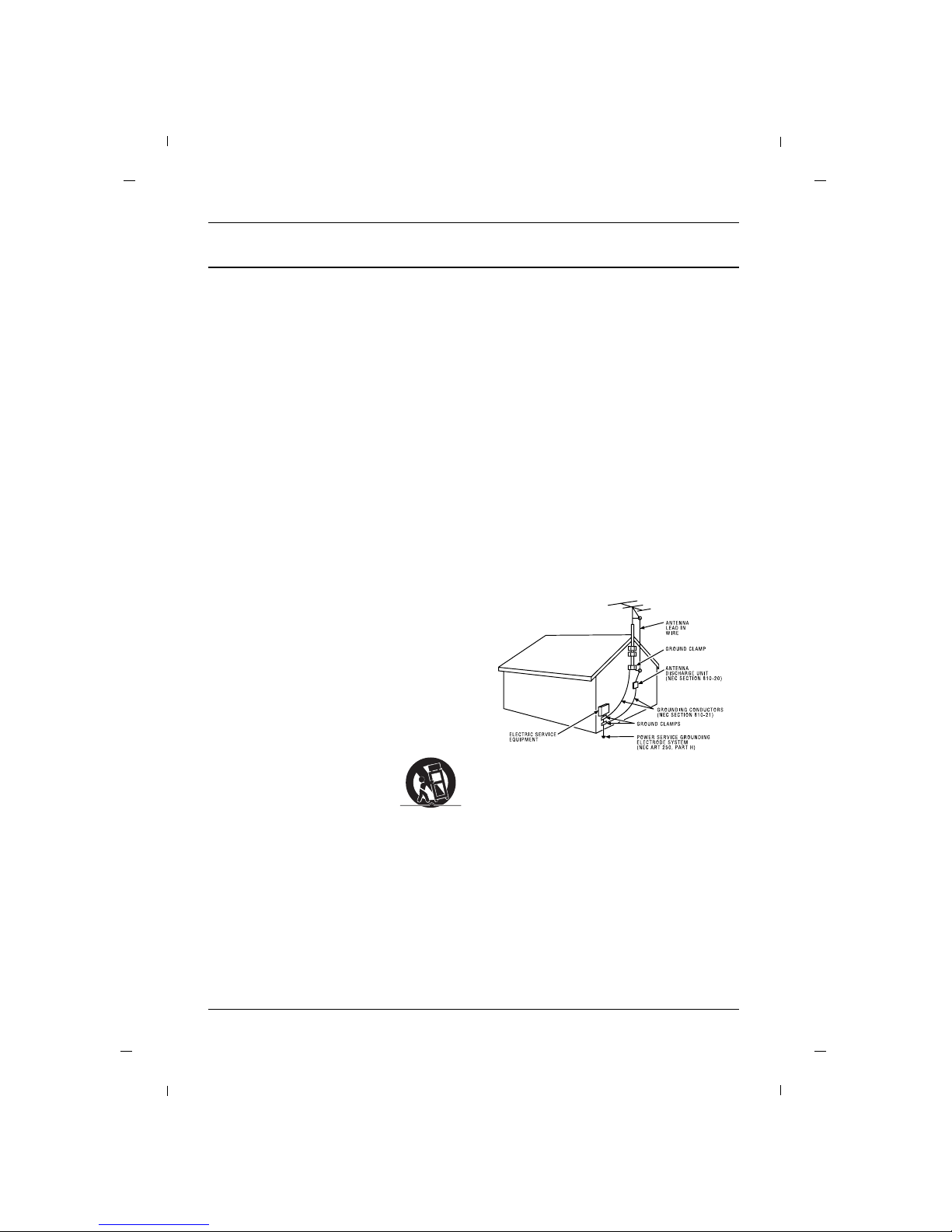
15. If an outside antenna or cable system is connected to the product, be sure the antenna or cable
system is grounded so as to provide some protection against voltage surges and built-up static
charges. Section 810 of the National Electrical
Code, ANSI/NFPA No. 70-1984 (Section 54 of
Canadian Electrical Code, Part 1) provides information with respect to proper grounding of the
mast and supporting structure, grounding of the
leadin wire to an antenna-discharge unit, size of
grounding conductors, location of antenna-discharge unit, connection to grounding electrodes,
and requirements for the grounding electrode.
See following example.
Page 6

Table of Contents
6
Important Information ..............................................2
IMPORTANT SAFETY INSTRUCTIONS ........................5
Chapter 1: Connections and Setup
Things to Consider Before You Connect ..................7
Protect Against Power Surges ........................7
Protect Devices from Overheating..................7
Position Cables Properly to Avoid Audio
Interference ......................................................7
Use Indirect Light ............................................7
Remote Control ................................................7
Check Supplied Parts........................................7
Controls And Connectors ..........................................8
Front Panel ......................................................8
Rear Panel ........................................................9
Connections ..............................................................10
Wall mount Installation ................................10
Desktop Pedestal Installation ........................10
Parts for stand assembly ................................11
Stand Installation ..........................................12
Swivel Stand ..................................................13
Attaching the TV to a desk ..........................13
Antenna Connection......................................14
VCR Connection..............................................15
DVD Connection ............................................16
HDSTB Connection ........................................17
External A/V Source........................................19
Digital Audio Out ..........................................19
PC Connection ................................................20
Resolution ......................................................21
Chapter 2: Using the Remote Control
Remote............................................................22
Put Batteries in the Remote ..........................23
Chapter 3: How to clone TV
Cloning............................................................24
Chapter 4: Basic Operation
Plug in the TV ................................................26
Turn on the TV................................................26
Channel Scan ..................................................26
Channel Selection ..........................................26
Volume Adjustment ......................................26
Sound Mute ....................................................26
Source Selection ............................................27
Language Selection........................................27
Chapter 5: Using the TV's Features
On Screen Menus ....................................................28
Setting up the TV Channel ....................................29
Auto Memorizing (Channel Search) ............29
Channel List ....................................................30
Fine Tune ........................................................31
Digital Signal Strength ..................................31
Remapped Channel........................................32
Picture Controls ........................................................33
Adjusting The Picture Controls ....................33
Manual Picture Controls ................................34
Color Temperature ........................................35
Screen Format ................................................36
Noise Reduction ............................................37
Film Mode ......................................................37
Sound Controls ........................................................38
Adjusting The Sound Controls ......................38
Manual Sound Controls ................................38
Balance............................................................39
Digital Output ................................................40
Internal Speakers............................................41
Surround ........................................................41
Auto Volume ..................................................42
Analog Audio Settings ..................................42
Digital Audio Language Settings ..................43
Minimum Volume ..........................................43
Maximum Volume..........................................44
Power On Volume ..........................................44
Time Setting ............................................................45
Auto Time Settings ........................................45
Manual Time Settings ....................................46
Daylight Saving ..............................................47
Time Zone Settings ........................................47
Auto On Time Settings ..................................48
Auto Off Time Settings..................................48
Auto Off..........................................................49
Parental Control ......................................................50
Entering your password ................................50
Set Block Hour. ..............................................51
TV Ratings for USA ........................................52
Movie Ratings ................................................54
English TV Ratings for Canada ......................55
French TV Ratings for Canada ......................56
Downloadable Rating ....................................57
Captions ....................................................................58
Turn Captions On/Off ....................................58
Closed Caption - Analog................................59
Closed Caption - Digital ................................60
Digital Closed Caption Options ....................61
Setup Menus ............................................................62
SI Vender Select..............................................62
Power On Channel ........................................62
A/D Channel Merge........................................63
Menu Language ............................................63
Menu Transparency........................................64
Front Panel Lock ............................................64
Power On Source............................................65
Setting the PC Mode................................................66
Automatic Screen Adjustment ......................66
Manual Screen Adjustment ..........................67
Specification ............................................................68
Chapter 6: Other Information
Troubleshooting ......................................................69
Limited Warranty ....................................................70
Care and Cleaning ....................................................71
CHILD SAFETY ..........................................................72
Page 7

Graphics contained within this publication are for representation only.
Chapter 1 7
Chapter 1: Connections and Setup
Things to Consider Before You Connect
• Connect all devices before you plug any of their power cords into the wall outlet or power strip. Never
plug your TV into an outlet that is controlled by a wall switch.
• Turn off the TV and/or device(s) before you connect or disconnect any cables.
• Make sure all antennas and cables are properly grounded. Refer to the Important Safety Instructions at
the beginning of the User's Guide.
Protect Against Power Surges
• Don’t block ventilation holes on any of the devices. Arrange the devices so that air can circulate freely.
• Don’t stack devices.
• If you place devices in a stand, make sure you allow adequate ventilation.
• If you connect an audio receiver or amplifier, place it on the top shelf so the heated air from it won’t flow
around other devices.
Protect Devices from Overheating
• Insert each cable firmly into the designated jack.
• If you place devices above the TV, route all cables down the side of the back of the TV instead of straight
down the middle.
• If your antenna uses 300-ohm twin lead cables, do not coil the cables. Also, keep the twin lead cables
away from audio/video cables.
•
Use shielded interface cables with ferrite cores to maintain compliance for this product.
Position Cables Properly to Avoid Audio Interference
Don’t place the TV where sunlight or room lighting will be directed toward the screen. Use soft or indirect
lighting.
Use Indirect Light
You will need a master remote or USB Cloner to set up the TV. Contact your RCA Commercial Distributor to
purchase these.
Remote Control
Check that the following parts were packed with your product.
Check Supplied Parts
Power Cord Owner’s Manual
Note
- If you need to replace your remote, call 1-800-RCA-2161. A shipping and handling fee, and the appropriate sales tax, will be charged upon ordering.
- Stand Base, Stand Body images shown may differ from your TV.
Stand Base Stand Body
1 2 3
4 5 6
7 8 9
0
SYSTEM
GUIDESLEEPSKIP
CCGO BACK
ANTENNAINPUT
SOUND
MENU OK INFO
CLEAR
MUTE
CH
VOL VOL
CH
ON-OFF
C O M M E R C I A L
R130K1
Remote
(Optional)
Page 8

Chapter 1: Connections and Setup
Chapter 18
Front Panel
VOL SOURCE MENUCH
VOL SOURCE MENUCH
12345
6
Note
- Image shown may differ from your TV.
1. VOL- / VOL+
Adjusts sound level and menu settings.
2. CH / CH
Select a channel.
3. SOURCE
Selects the TV, AV, COMPONENT, HDMI1, HDMI2 or PC mode.
4. MENU
Display on screen menus.
5. POWER
Switches the set on or off.
6. Power Indicator
Illuminates to bright blue when the TV is on. When the TV is powered off, this LED is also off.
Remote control sensor
Accepts the IR signal of remote controller.
Page 9
Chapter 1
Chapter 1: Connections and Setup
9
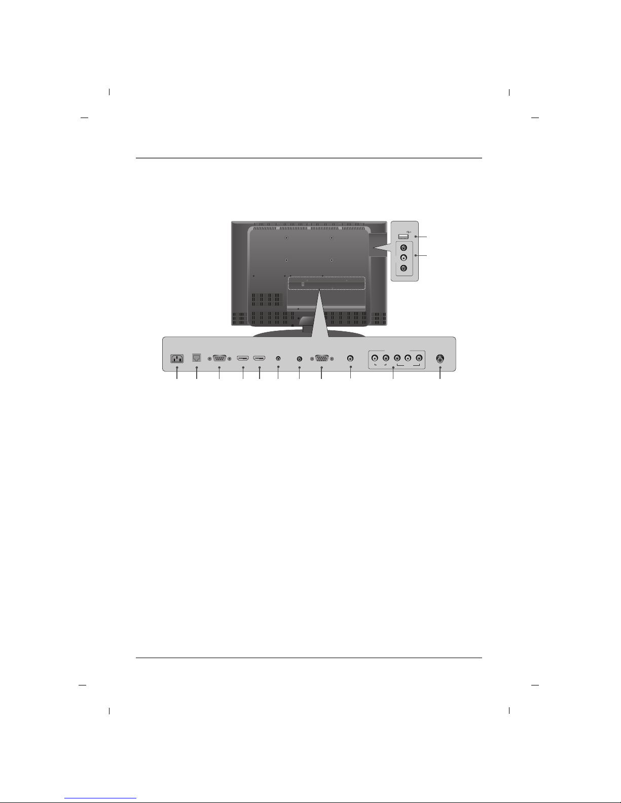
Rear Panel
1. AC IN
This TV operates on AC power.
2. MTI
3. SERVICE
This port is used for service.
4. HDMI IN2
Connect to the HDMI jack for device with HDMI
output.
5. HDMI/DVI IN1
Connect to the HDMI jack for device with HDMI
output.
This input can also be used as a DVI connection
with separate analog audio inputs.
6. SERVICE (AV)
This port is used for service.
7. AUDIO IN (RGB/DVI)
Connect to the audio output jack on your PC.
8. RGB IN (PC)
Connect to the video output jack on your PC.
9. DIGITAL AUDIO OUT(COAXIAL)
Connect digital audio to various types of equipment.
10.COMPONENT IN (YPbPr)
Video/Audio inputs for Component.
11.ANTENNA/CABLE IN
Connect to your antenna or cable box for TV signal.
12.USB IN (SERVICE ONLY)
Used for software updates.
13.AV
Connects to your Audio/Video devices using a
composite (Yellow/Red/White) cable.
12
13
USB IN
AV
VIDEO L - AUDIO - R
AUDIO IN
(RGB/DVI)
SERVICE
3
RGB IN
(PC)
87
ANTENNA/
CABLE IN
11
HDMI/DVI IN
1
5
HDMI IN
2
41
AC IN
6
SERVICE
(AV)
2
MTI
10
VIDEO
YPbPr
LR
AUDIO
COMPONENT IN
DIGITAL AUDIO
OUT(COAXIAL)
9
Note
- Image shown may differ from your TV.
Page 10
Chapter 1: Connections and Setup
Chapter 110
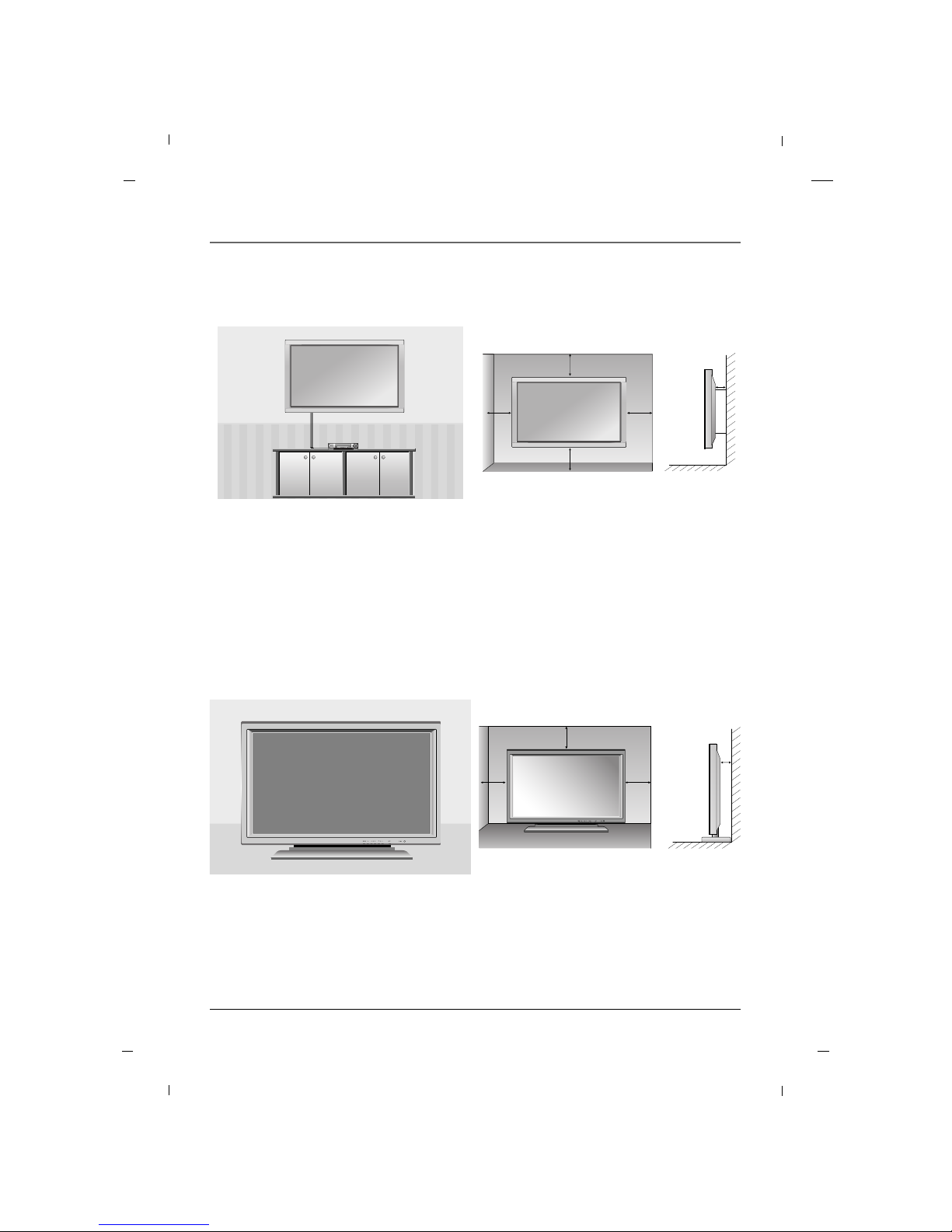
Wall mount Installation
4 inches
4 inches
4 inches
4 inches
4 inches
The set can be installed on a wall as shown above.
For proper ventilation, allow a clearance of 4 inches on all four sides from the wall.
Detailed instructions are available from your dealer, refer to the optional Wall Mounting Bracket Installation
and Setup Guide. (Wall Mount Sold Separately)
Note
- This Television should be installed by a Qualified Service Personnel.
Desktop Pedestal Installation
4 inches
4 inches
4 inches
4 inches
The set can be mounted on a desk as shown above.
For proper ventilation, allow a clearance of 4 inches on each side from the wall.
Detailed instructions are available from your dealer.
Note
- Image shown may differ from your TV.
Page 11
Chapter 1
Chapter 1: Connections and Setup
11
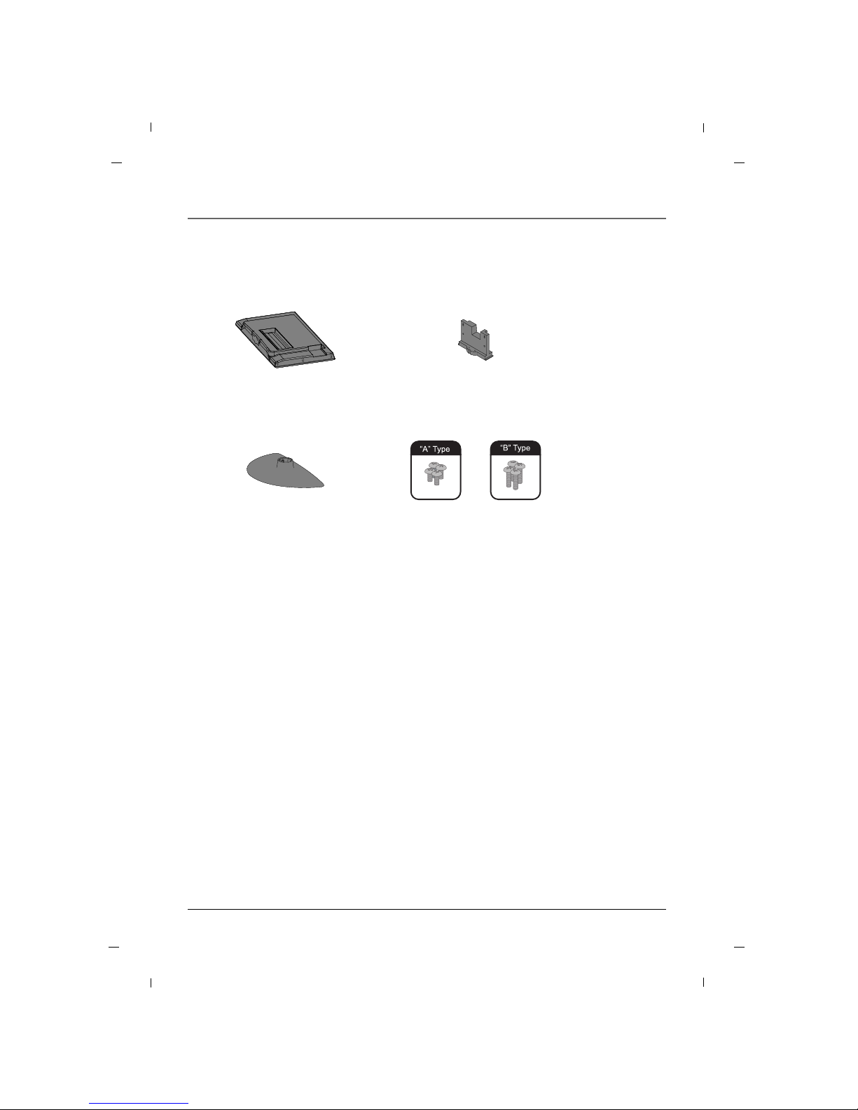
Parts for stand assembly
TV Stand Body
Stand Base 4 - A type bolts
4 - B type bolts
Page 12
Chapter 1: Connections and Setup
12
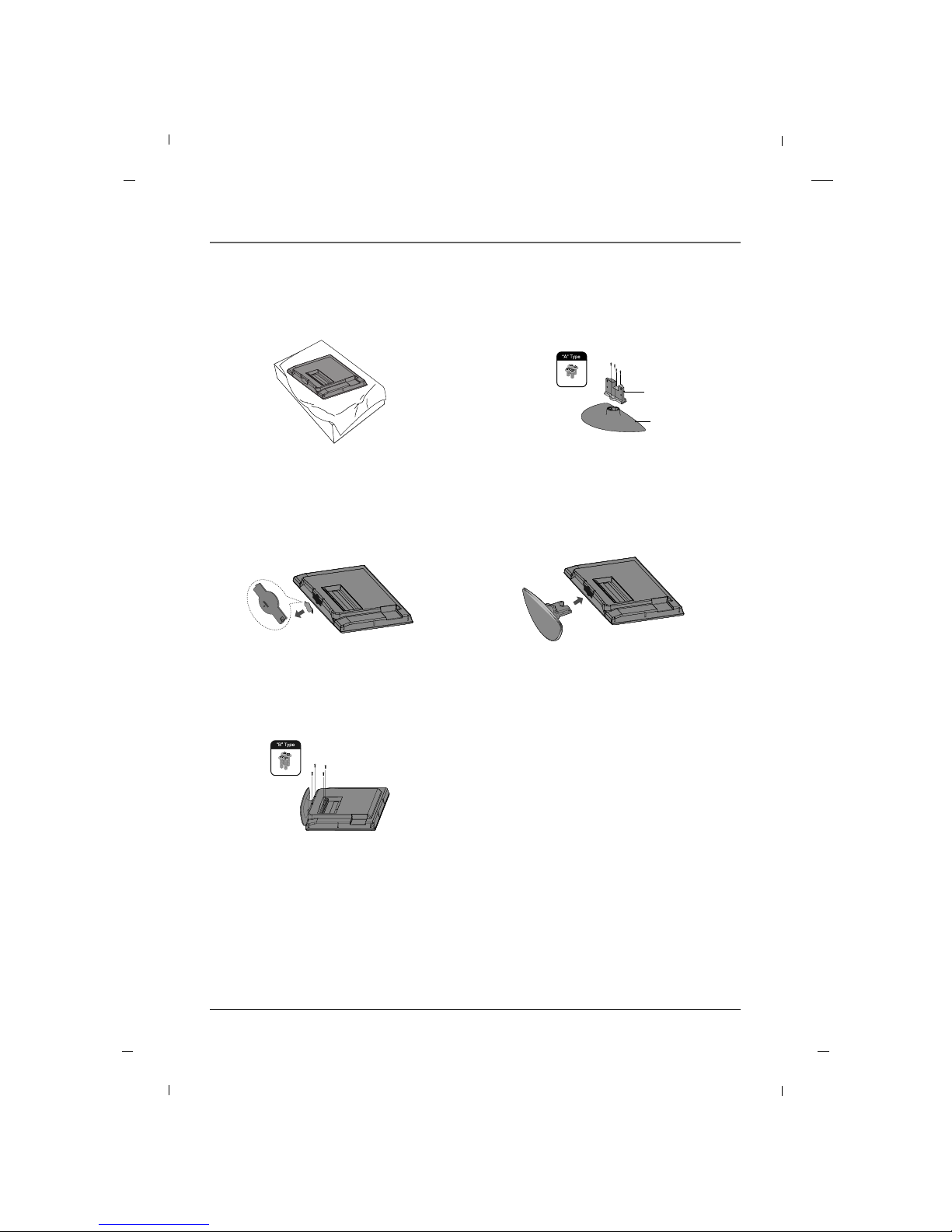
1. Carefully place the product screen
side down on a cushioned surface
that will protect the product and
screen from damage.
2. Using the screws provided assemble
the stand body with the stand base as
shown.
3. Remove the included stand cover
from the product.
5. Install the 4 bolts securely, in the back
of the product in the holes provided.
4. Assemble the product stand with the
product as shown.
Stand
body
Stand
base
Stand Installation
Note
- Image shown may differ from your TV.
- When mounting TV on the wall, install the included Stand Cover over the hole for the stand. Press the
Stand Cover into the TV until you hear it click.
Chapter 1
Page 13
Chapter 1: Connections and Setup
13Chapter 1
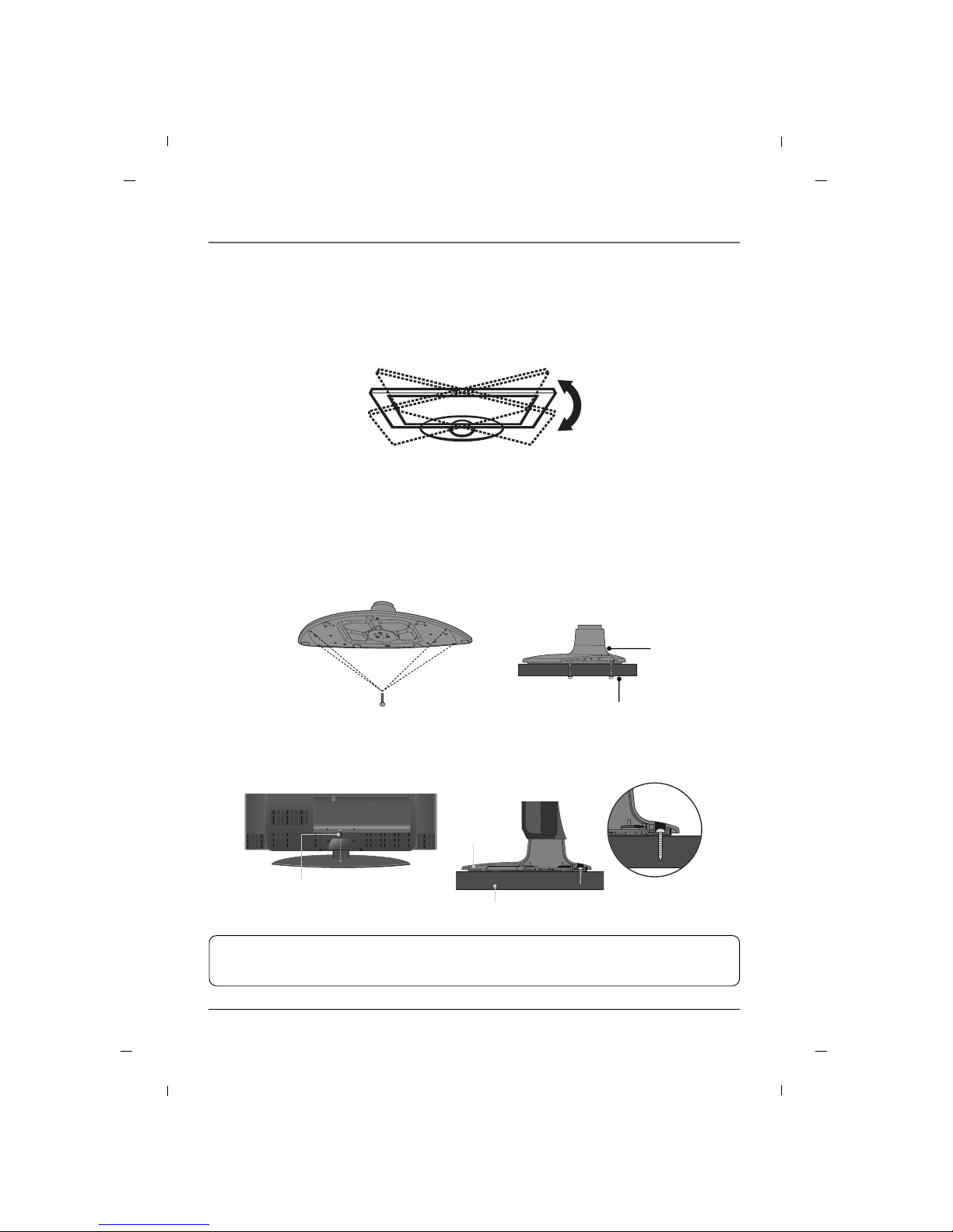
Swivel Stand
The TV can be conveniently swiveled on its stand 90° to the left or right to provide the optimum viewing
angle.
Attaching the TV to a desk
The TV must be attached to a desk so it cannot be pulled in a forward/backward direction, potentially
causing injury or damaging the product.
* Screws - M5 x L (Table depth + 8~10 mm)
ex) table depth: 15mm, Screws: M5 x 25
1-Screw
(not provided as parts of the
product)
Desk
Stand
Stand
Desk
4-Screws
(not provided as parts of the product)
WARNING
To prevent TV from falling over, the TV should be securely attached to the floor/wall per installation
instructions. Tipping, shaking, or rocking the machine may cause injury.
Page 14
Chapter 1: Connections and Setup
14 Chapter 1
ANTENNA/
CABLE IN
VIDEO
YPbPr
LR
AUDIO
COMPONENT IN
DIGITAL AUDIO
OUT(COAXIAL)
Rear panel of the set
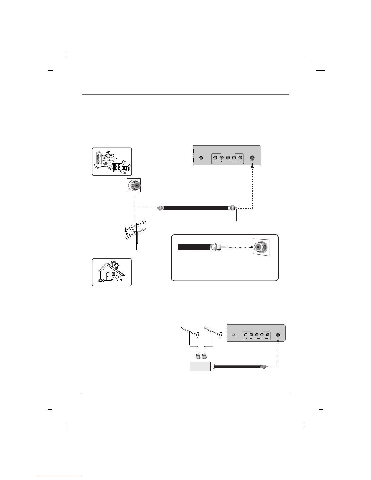
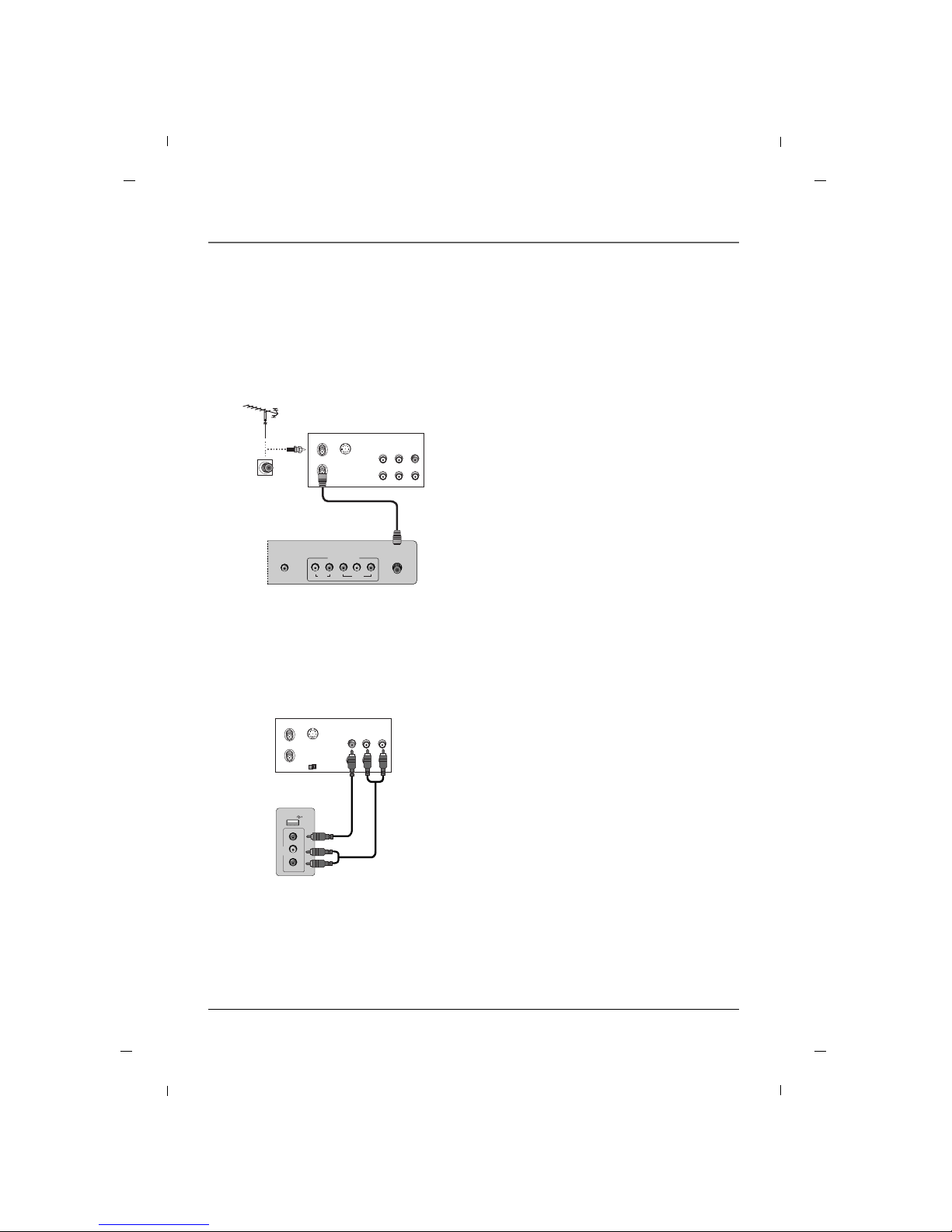
Antenna Connection
Note
- To improve the picture quality in a poor signal
area, please purchase a signal amplifier and
install properly.
- If the antenna is not installed properly, contact
your dealer for assistance.
ANTENNA/
CABLE IN
VIDEO
YPbPr
LR
AUDIO
COMPONENT IN
DIGITAL AUDIO
OUT(COAXIAL)
Rear panel of the set
Multi-family Dwellings/ Apartments
(Connect to wall antenna socket)
Single-family Dwellings /Houses
(Connect to wall jack for outdoor antenna)
Wall Antenna Socket
Outdoor Antenna
RF Coaxial Wire (75 ohm)
Turn clockwise to tighten.
Be careful not to bend the bronze wire when
connecting to an antenna port.
* Separately purchase a RF Coaxial Wire(75 ohm)
Signal
Amplifier
VHF UHF
VHF
UHF
Page 15
15
Chapter 1: Connections and Setup
Chapter 1
VCR Connection
AA When connecting with an antenna
ANTENNA/
CABLE IN
VIDEO
YPbPr
LR
AUDIO
COMPONENT IN
DIGITAL AUDIO
OUT(COAXIAL)
ANT IN
ANT OUT S-VIDEO
IN
OUT
(R) AUDIO (L) VIDEO
1. Connect the Antenna out socket of the VCR to
the Antenna input socket on the TV.
2. Power up the VCR and Television.
3. Tune the TV to the channel output by the VCR.
(typically ch.3 or 4.)
4. Refer to the VCR manual for operating instructions.
VCR
Rear panel of the set
- To avoid picture noise (interference), leave an adequate distance between the TV and the VCR.
AA When connecting with an RCA cable
USB IN
AV
VIDEO L - AUDIO - R
ANT IN
ANT OUT S-VIDEO
IN
OUT
(L) AUDIO (R)VIDEO
OUTPUT
SWITCH
1. Connect the AUDIO/VIDEO port between TV and
VCR. Match the jack colors (Video = yellow, Audio
Left = white, and Audio Right = red)
2. Insert a video tape into the VCR and press PLAY
on the VCR.
3. Select the AV input source using the INPUT but-
ton on the remote control.
4. Refer to the VCR manual for operating instructions.
VCR
Side panel of the set
Page 16
Chapter 1: Connections and Setup
16
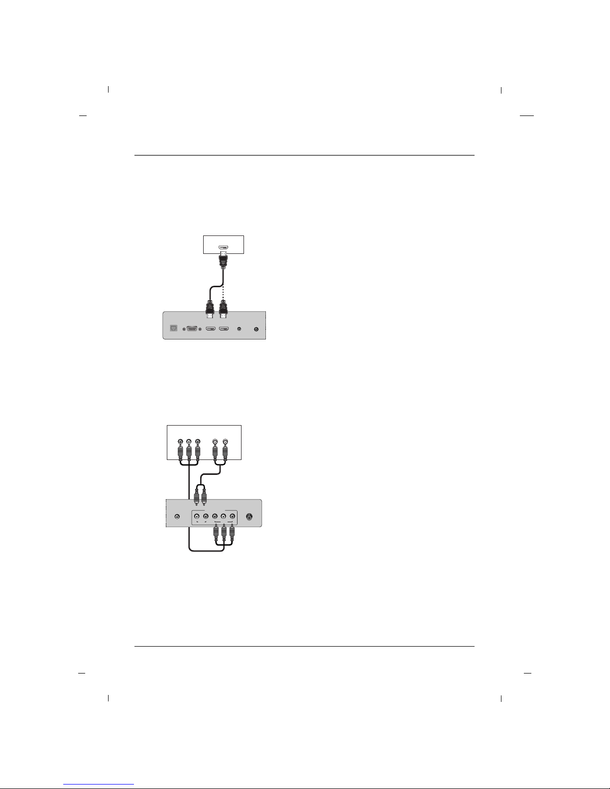
AA When connecting with a Component cable
ANTENNA/
CABLE IN
VIDEO
YPb Pr
LR
AUDIO
COMPONENT IN
DIGITAL AUDIO
OUT(COAXIAL)
(L) AUDIO (R)
Y
Pb Pr
1. Connect the video outputs (Y, PB, PR) of the DVD
to the COMPONENT VIDEO(Y, Pb, Pr) port on
the set.
2. Connect the audio outputs of the DVD to the
COMPONENT AUDIO L, R port on the set.
3. Turn on the DVD player, insert a DVD.
4. Select COMPONENT source using the INPUT but-
ton on the remote control.
5. Refer to the DVD player's manual for operating
instructions.
DVD
Rear panel of
the set
DVD Connection
AA When connecting with a HDMI cable
AUDIO IN
(RGB/DVI)
SERVICE HDMI/DVI IN
1
HDMI IN
2
SERVICE
(AV)
MTI
HDMI-DVD OUTPUT
1. Connect the HDMI output of the DVD to the
HDMI IN1 or HDMI IN2 port on the set.
2. Select HDMI1 or HDMI2 input source using the
INPUT button on the remote control.
3. Refer to the DVD player's manual for operating
instructions.
DVD
Rear panel of the set
Chapter 1
Page 17
Chapter 1: Connections and Setup
17Chapter 1
- This TV can receive Digital Over-the-air/Cable signals without an external digital set-top box.
However, if you do receive Digital signals from a digital set-top box or other digital external device, refer
to the figure as shown below.
HDSTB Connection
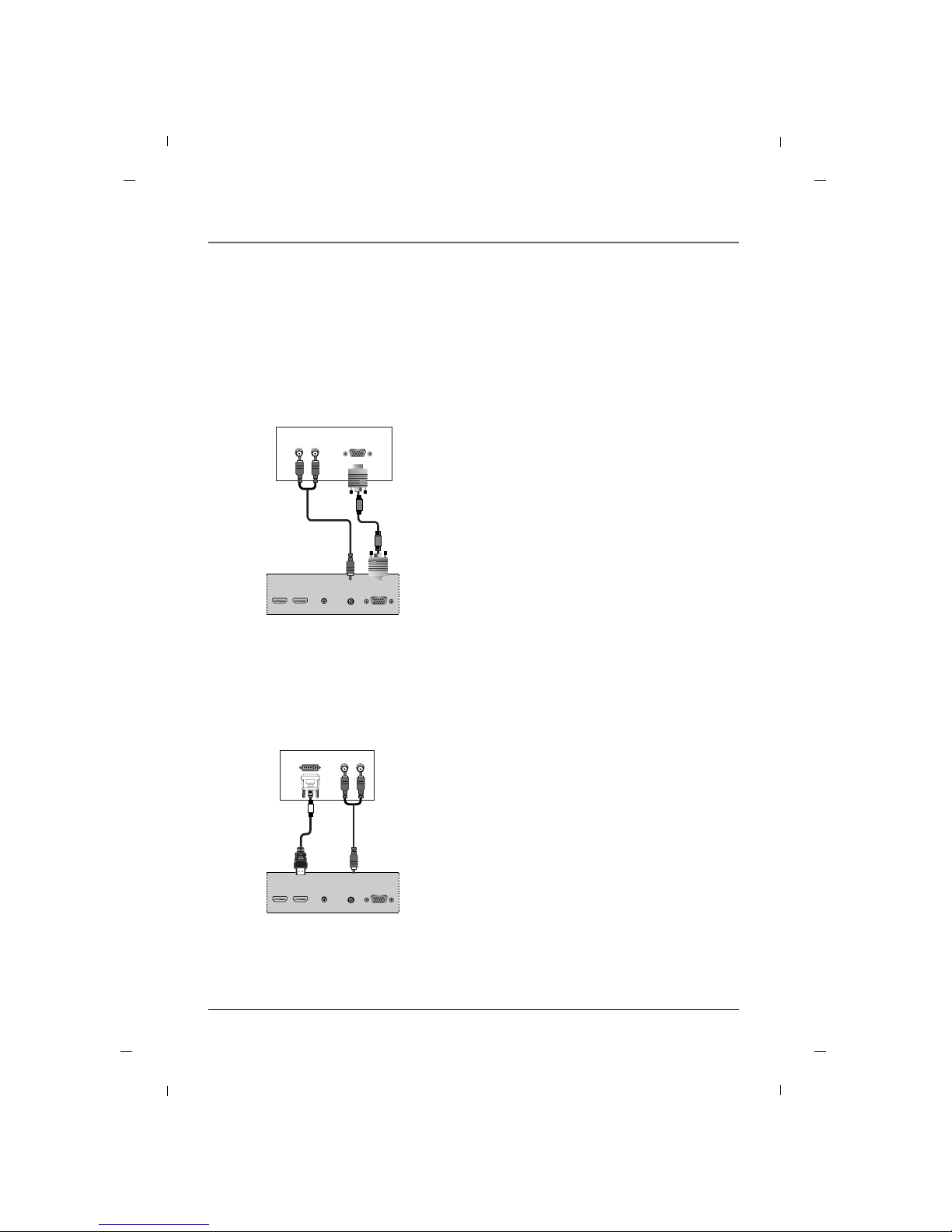
AA When connecting with a D-Sub 15 pin cable
AUDIO IN
(RGB/DVI)
RGB IN
(PC)
HDMI/DVI IN
1
HDMI IN
2
SERVICE
(AV)
(R) AUDIO (L) RGB-DTV OUTPUT
1. Connect the RGB output of the digital set-top
box to the RGB IN (PC) port on the set.
2. Connect the audio outputs of the set-top box to
the AUDIO IN (RGB/DVI) port on the set.
3. Turn on the digital set-top box.
4. Select PC input source using the INPUT button on
the remote control.
5. Refer to the digital set-top box manual for operating instructions.
Digital Set-top Box
Rear panel of the set
AA When connecting with a HDMI to DVI cable
AUDIO IN
(RGB/DVI)
RGB IN
(PC)
HDMI/DVI IN
1
HDMI IN
2
SERVICE
(AV)
DVI-DTV OUTPUT
(R) AUDIO (L)
1. Connect the DVI output of the digital set-top box
to the HDMI/DVI IN1 port on the set.
2. Connect the audio outputs of the set-top box to
the AUDIO IN (RGB/DVI) port on the set.
3. Turn on the digital set-top box.
4. Select HDMI1 input source using the INPUT button on the remote control.
5. Refer to the digital set-top box manual for operating instructions.
Digital Set-top Box
Rear panel of the set
Page 18
Chapter 1: Connections and Setup
18 Chapter 1
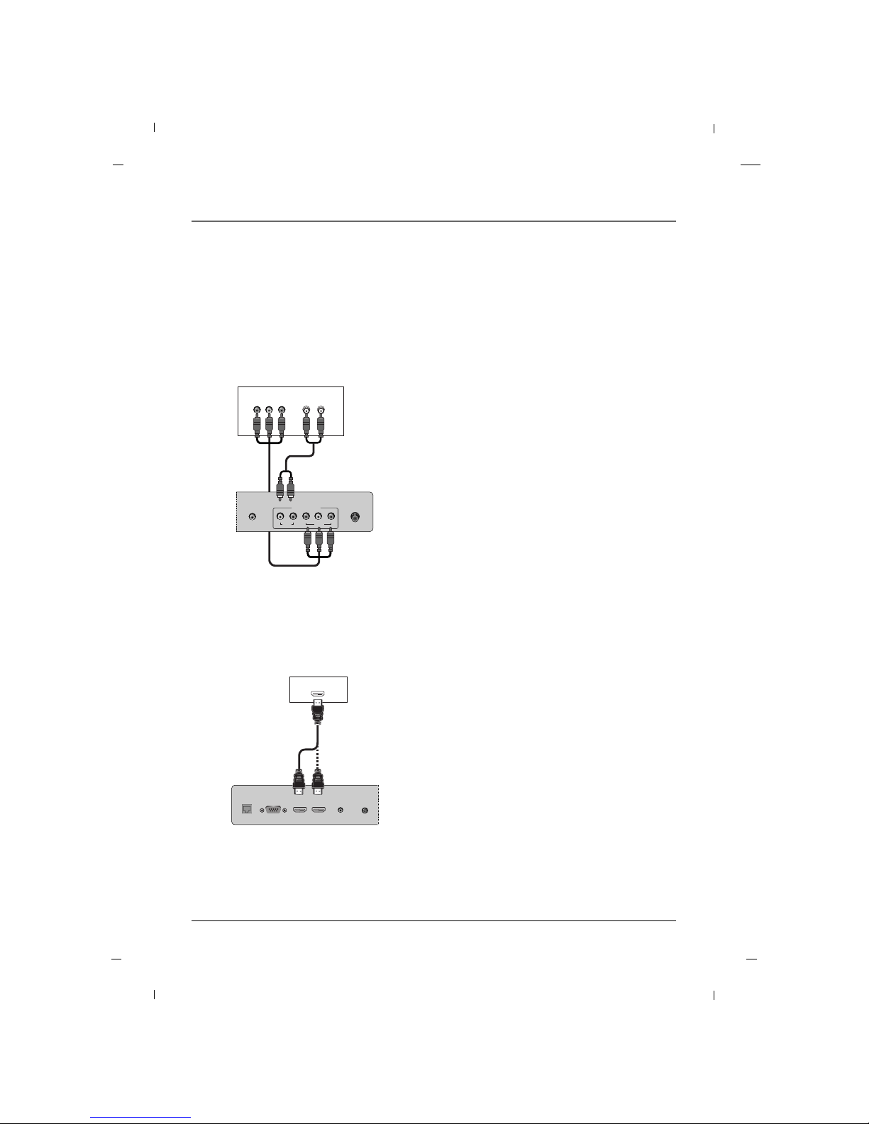
AA When connecting with a Component cable
ANTENNA/
CABLE IN
VIDEO
YPb Pr
LR
AUDIO
COMPONENT IN
DIGITAL AUDIO
OUT(COAXIAL)
(L) AUDIO (R)
Y
Pb Pr
1. Connect the video outputs (Y, PB, PR) of the digital set-top box to the COMPONENT VIDEO(Y,
Pb, Pr) port on the set.
2. Connect the audio outputs of the digital set-top
box to the COMPONENT AUDIO L, R port on the
set.
3. Turn on the digital set-top box.
4. Select COMPONENT source using the INPUT but-
ton on the remote control.
5. Refer to the digital set-top box manual for operating instructions.
Digital Set-top Box
Rear panel of
the set
AA When connecting with a HDMI cable
HDMI-DTV OUTPUT
AUDIO IN
(RGB/DVI)
SERVICE HDMI/DVI IN
1
HDMI IN
2
SERVICE
(AV)
MTI
1. Connect the HDMI output of the digital set-top
box to the HDMI IN1 or HDMI IN2 port on the
set.
2. Turn on the digital set-top box.
3. Select HDMI1 or HDMI2 input source using the
INPUT button on the remote control.
4. Refer to the digital set-top box manual for operating instructions.
Digital Set-top Box
Rear panel of the set
Page 19
Chapter 1: Connections and Setup
19Chapter 1
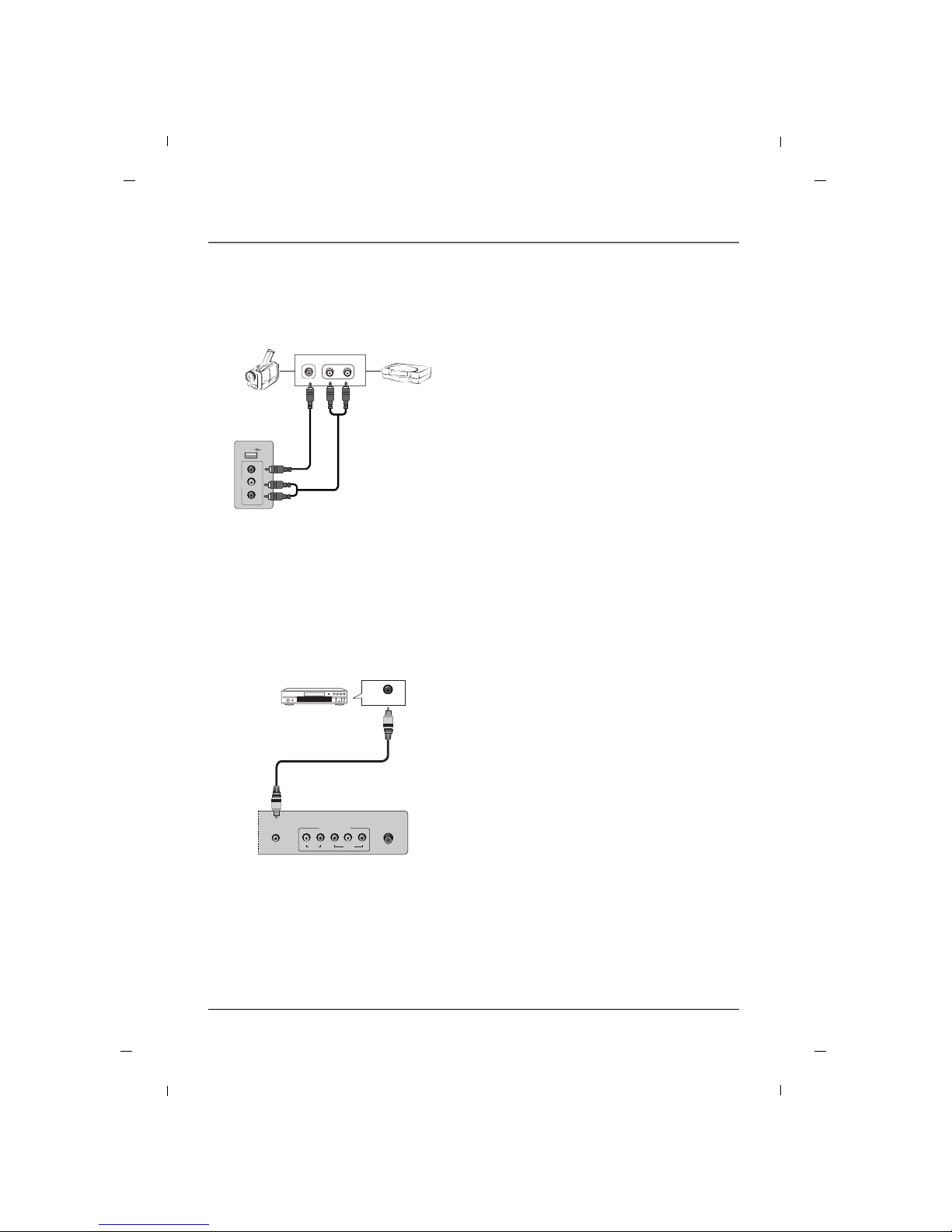
L-AUDIO-RVIDEO
OUT
USB IN
AV
VIDEO L - AUDIO - R
1. Connect the AUDIO/VIDEO port between TV and
external equipment. Match the jack colors (Video
= yellow, Audio Left = white, and Audio Right =
red)
2. Select the AV input source using the INPUT but-
ton on the remote control.
3. Operate the corresponding external equipment.
4. Refer to the external equipment manual for operating instructions.
Camcorder Video game set
External A/V Source
Side panel of the set
Digital Audio Out
ANTENNA/
CABLE IN
VIDEO
YPb Pr
LR
AUDIO
COMPONENT IN
DIGITAL AUDIO
OUT(COAXIAL)
DIGITAL AUDIO
IN(COAXIAL)
1. Connect one end of the optical cable to the TV’s
DIGITAL AUDIO OUT(COAXIAL) port.
2. Connect the other end of the coaxial cable to the
digital audio input on the audio equipment.
3. Refer to the external audio equipment manual
for operation.
Audio Equipment
Rear panel of the set
Page 20
Chapter 1: Connections and Setup
20 Chapter 1
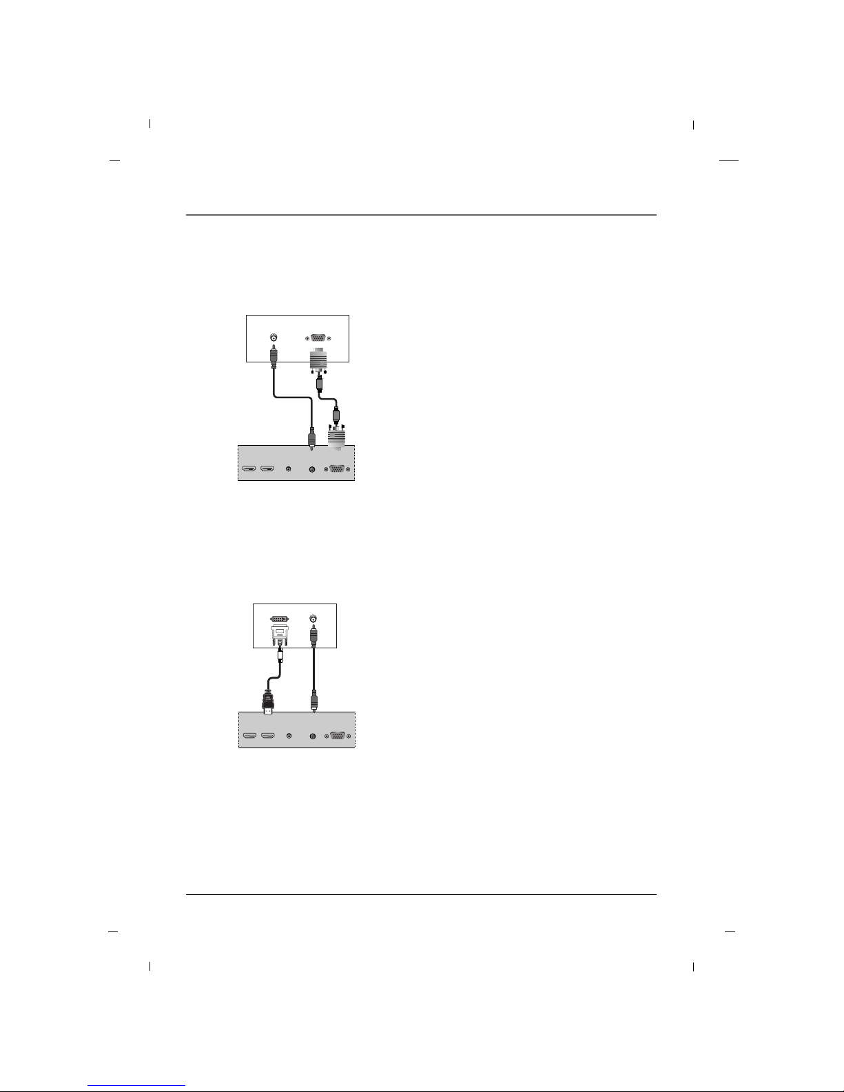
AA When connecting with a D-Sub 15 pin cable
AUDIO OUT
AUDIO IN
(RGB/DVI)
RGB IN
(PC)
HDMI/DVI IN
1
HDMI IN
2
SERVICE
(AV)
RGB-DTV OUTPUT
1. Connect the RGB output of the PC to the RGB IN
(PC) port on the set.
2. Connect the PC Audio Output to the AUDIO IN
(RGB/DVI) port on the TV using a male-to-male
3.5mm mini jack.
3. Turn on both the PC and TV.
4. Select PC input source using the INPUT button on
the remote control.
PC
Rear panel of the set
PC Connection
AA When connecting with a HDMI to DVI cable
AUDIO OUT
AUDIO IN
(RGB/DVI)
RGB IN
(PC)
HDMI/DVI IN
1
HDMI IN
2
SERVICE
(AV)
DVI-DTV OUTPUT
1. Connect the DVI Output on the PC to the
HDMI/DVI IN1 Input port on the TV.
2. Connect the PC Audio Output to the AUDIO IN
(RGB/DVI) jack on the TV using a male-to-male
3.5mm mini jack.
3. Turn on both the PC and TV.
4. Select HDMI1 input source using the INPUT button on the remote control.
PC
Rear panel of the set
Page 21
Chapter 1: Connections and Setup
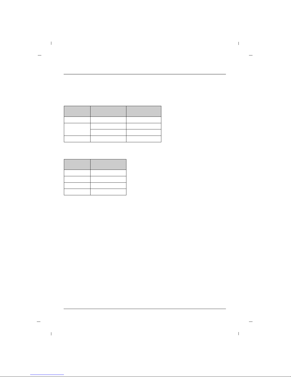
21Chapter 1
31.47
35.16
37.88
48.36
59.94
56.25
60.32
60.00
Horizontal
Frequency (kHz)
Vertical
Frequency (Hz)
640 x 480
800 x 600
1024 x 768
Resolution
AA PC
60.000
60.000
60.000
60.000
Vertical
Frequency (Hz)
480/60P
720/60P
1080/60I
1080/60P
Resolution
AA HDMI
Resolution
Note
a. The synchronization input form is separate.
b. If the resolution is not supported, ‘No Signal!’ message will be displayed.
Page 22
22 Chapter 2
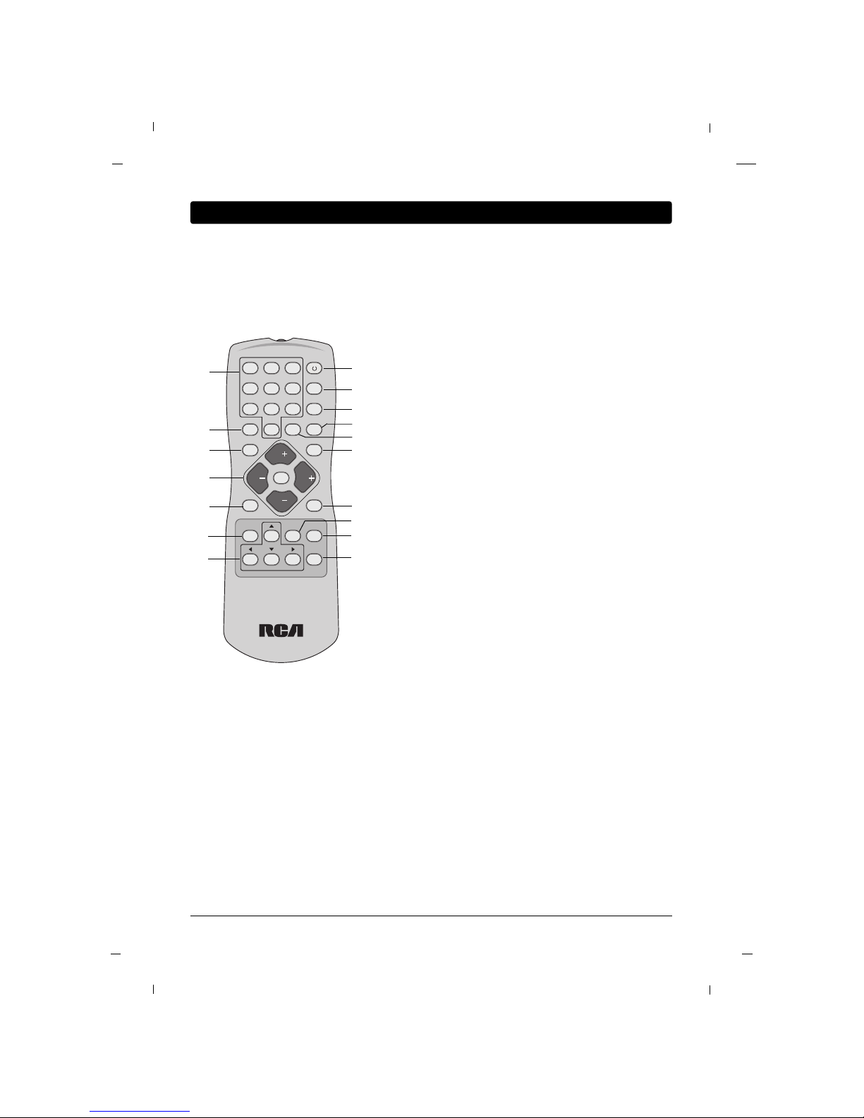
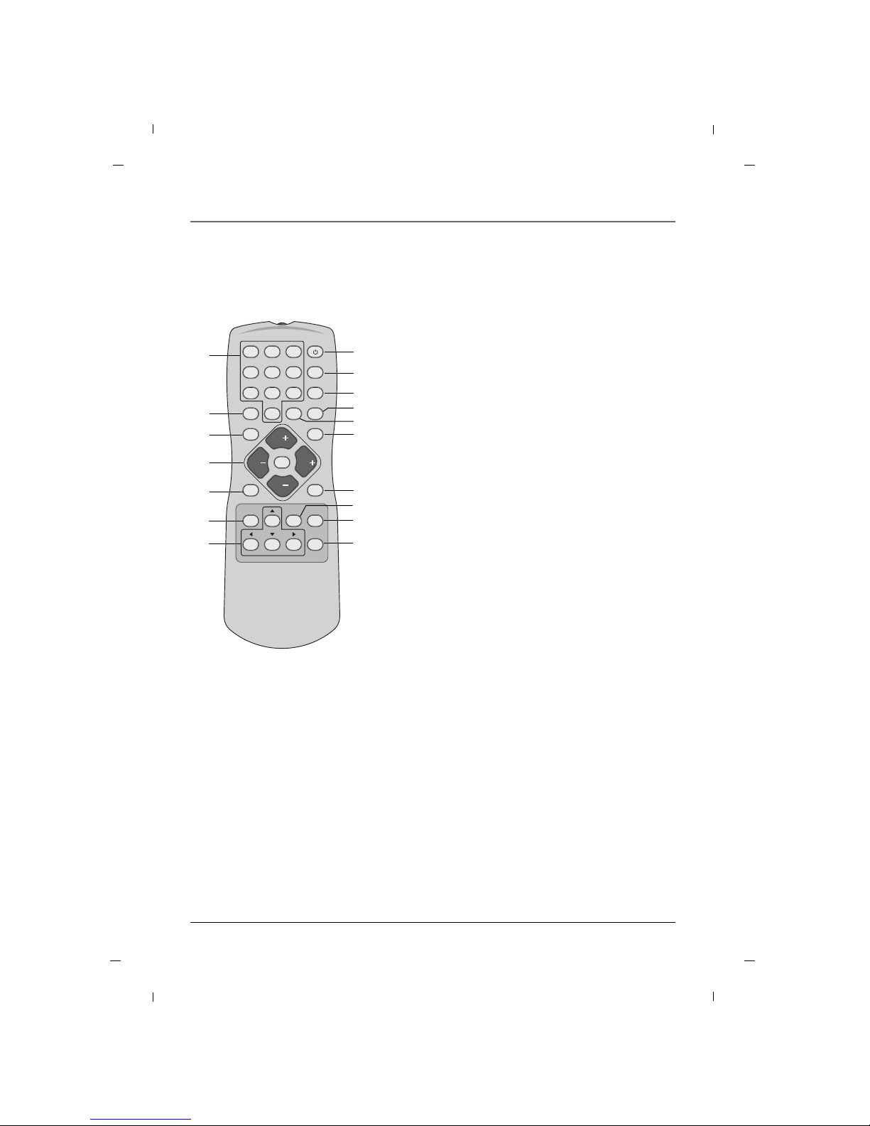
The basic remote control (R130K1) is used by the viewer for basic operating functions. It is designed so that
the viewer cannot alter certain master remote-specified features. The Sleep, Closed Captioning, and Channel
Guide features can be accessed directly with remote buttons.
1. NUMBER BUTTONS
Selects channel numbers.
2. ON-OFF
Switches the set on or off.
3. SYSTEM
Unused.
4. SOUND
Recalls your preferred sound setting.
5. SKIP
Unused
6. SLEEP
Sets the sleep timer.
7. GUIDE
Display “Channel List” menu.
8. GO BACK
Return to the previous channel.
9. CC
Select the Caption menu directly.
10. VOL + / VOL -
Adjusts sound level.
CH + / CH -
Select a channel.
MUTE
Switches the sound on or off.
11. INPUT
Selects the TV, AV, COMPONENT, HDMI1, HDMI2 or PC
mode.
12. ANTENNA
Unused
13. MENU
Displays “Basic” on screen menu.
There are 2 remotes for this TV;
R130K1 - user Remote. This remote displays a basic user
menu when the menu key is pressed.
R130K2 - installer Remote. This remote displays an
installer menu when the menu key is pressed.
14. Navigational Controls
Adjusts menu settings.
Selects menu item.
15. OK
Accepts your selection.
16. INFO
Display the current channel information.
17. CLEAR
Exit from any OSD.
1 2 3
4 5 6
7 8 9
0
SYSTEM
GUIDESLEEPSKIP
CCGO BACK
ANTENNAINPUT
SOUND
MENU OK INFO
CLEAR
MUTE
CH
VOL VOL
CH
ON-OFF
C O M M E R C I A L
R130K1
1
5
8
10
11
2
3
4
6
9
12
7
Basic(User) Remote
15
16
17
13
14
Chapter 2: Using the Remote Control
Page 23
Chapter 2: Using the Remote Control
23Chapter 2
1. NUMBER BUTTONS
Selects channel numbers.
2. ON-OFF
Switches the set on or off.
3. SYSTEM
Unused.
4. RESET
Unused.
5. SKIP
Unused
6. SLEEP
Sets the sleep timer.
7. GUIDE
Display “Channel List” menu.
8. GO BACK
Return to the previous channel.
9. CC
Select the Caption menu directly.
10. VOL + / VOL -
Adjusts sound level.
CH + / CH -
Select a channel.
MUTE
Switches the sound on or off.
11. INPUT
Selects the TV, AV, COMPONENT, HDMI1, HDMI2 or PC
mode.
12. ANTENNA
Unused
13. MENU
Displays “Installer” on screen menu.
There are 2 remotes for this TV;
R130K1 - user Remote. This remote displays a basic user
menu when the menu key is pressed.
R130K2 - installer Remote. This remote displays an
installer menu when the menu key is pressed.
14. Navigational Controls
Adjusts menu settings.
Selects menu item.
15. OK
Accepts your selection.
16. INFO
Display the current channel information.
17. CLEAR
Exit from any OSD.
1 2 3
4 5 6
7 8 9
0
SYSTEM
GUIDESLEEPSKIP
CCGO BACK
ANTENNAINPUT
RESET
MENU OK INFO
CLEAR
MUTE
CH
VOL VOL
CH
ON-OFF
R130K2
MASTER
• Remove the battery compartment cover
from the back of the remote by pushing
the tab and lifting off the cover.
• Insert two fresh batteries. Make sure the
polarities (+ and -) are aligned correctly.
• Replace the cover.
Put Batteries in the Remote
The master remote control (R130K2) accesses all of the TV’s menus. It is used to customize the TV’s functionality for specific users or specific situations.
Master(Installer) Remote
1
5
8
10
11
2
3
4
6
9
12
7
15
16
17
13
14
Page 24

24
Chapter 3: How to clone TV
After you set up one television, you can copy the settings onto a USB stick and apply them to your other televisions.
You will need a properly configured USB Memory stick to learn the settings from your television.
Contact RCA Commercial Distribution(1-800-RCA-2161) to obtain an RCA USB Memory stick, or setup your
own memory stick by following the “Configuring your memory stick” section below.
1. Plug a USB key into the USB port of your PC.
2. Open Windows Explorer
3. Right Click on the USB drive in Windows Explorer and select “New” followed by “Folder.”
4. Name the folder, “CMSTDF.”
Exit NextMove
Cloning Main Menu
Restore Settings to TV
Save Settings to USB
Upload Firmware to TV
Information
GG
Back NextAdjust
Save Settings to USB
Source Model : DM-931KA
File Name Edit:
J
32
Back NoYe s
Save Settings to USB
Save Settings from TV
to J32LED--.tdf file in USB?
Back
Save Settings to USB
Settings saved from TV
to J32LED--.tdf file in USB
Chapter 3
Configuring your memory stick:
1. Press the MENU button to enter the on-screen
menu.
2. Press the Down or Up button to select the Setup
sub-menu and then press the OK button.
3. Press the Down or Up button to select the
Firmware Upgrade sub-menu and then press the
OK button.
4. Press the Right button to choose Save Settings to
USB and then press the Right button.
5. Edit filename by pressing Up/Down/Left/Right keys.
6. Press the Up key to write settings to the USB stick
Settings will be copied to USB drive.
Copying settings out of television:
To set up a USB key to you need to create a directory (folder) on the USB stick called CMSTDF.
Page 25

Chapter 3: How to clone TV
25
Exit NextMove
Cloning Main Menu
Restore Settings to TV
Save Settings to USB
Upload Firmware to TV
Information
GG
Back NextMove
Restore Settings To TV
Source Model : DM-931KA
File Name :
J32LED--.tdf
Back NoYe s
Restore Settings To TV
Restore Settings
to TV from
J32LED--.tdf file in USB?
Back
Restore Settings To TV
Settings restoreed to TV
from J32LED--.tdf file in USB
TV will restart in a few seconds
GG
Chapter 3
1. Press the MENU button to enter the on-screen
menu.
2. Press the Down or Up button to select the Setup
sub-menu and then press the OK button.
3. Press the Down or Up button to select the
Firmware Upgrade sub-menu and then press the
OK button.
4. Press the Right button to choose Restore Settings
to TV and then press the OK button.
5. Select the file to restore settings from the USB stick.
6. Press the Up key to restore settings from USB stick.
Settings will be copied to USB drive.
Placing settings into television from USB key:
Page 26

26 Chapter 4
Plug the end of the power cord into the back of the TV. Plug the other end into a grounded wall outlet.
Insert the plug completely into the outlet. Do not plug into an outlet controlled by a light switch.
Plug in the TV
Turn on your TV by pressing the Power button on the front of the TV or ON-OFF on the remote control.
Turn on the TV
This function automatically finds all channels available through the Antenna or Cable and stores them in
memory on the channel list.
Auto Memorizing
You can select a channel number with the CH + / CH - button or NUMBER buttons.
Channel Selection
Press the VOL+ / VOL- button to adjust the sound level.
Volume Adjustment
Press the MUTE button. The sound is switched off and the mute Icon appears.
To cancel mute mode, press the MUTE or VOL+ / VOL- button again.
Sound Mute
Chapter 4: Basic Operation
Page 27

27
Chapter 4: Basic Operation
Chapter 4
1. Press the INPUT button to change the input mode.
2. Press the Down or Up button to select your desired
mode.
3. Press the OK button to change your selected mode.
Source Selection
Input
TV
AV
COMPONENT
HDMI1
HDMI2
PC
EXIT
Menu Language
1. Press the MENU button to enter the on-screen
menu.
2. Press the Down or Up button to select Setup and
then press the OK button.
3. Press the Down or Up button to select the More
and then press the OK button.
4. Press the Down or Up button to select the Menu
Language and then press the OK button.
5. Press the Down or Up button to select your desired
language: English, Español or Français.
6. Press the MENU button to return to the previous
menu.
The menus can be shown on the screen in multiple languages.
First select your language.
11:20 PM
Sep.11,2010
Select Back
Menu
Back
Menu Language
Menu Transparency
Front Panel Lock
Power on Source
English
Español
Français
11:20 PM
Sep.11,2010
Move SelectOKBack
Menu
Back
Menu Language
Menu Transparency
Front Panel Lock
Power on Source
English
Semi Opaque
Off
TV
GG
Page 28

28 Chapter 5
Your TV’s OSD(On Screen Display) may differ slightly from what is shown in this manual.
1. Press the MENU button and then press the Down or Up button to select each menu.
2. Press the OK button and then Down, Up, Left and Right buttons to navigate to the available menus.
On Screen Menus
Picture MENU Sound MENU
Caption MENU
Setup MENU
Channel MENU
11:20 PM
Sep.11,2010
Move SelectOKExit
Menu
Antenna
Auto Memorizing
Channel List
Fine Tune
Signal Strength
Remapped Channel
11:20 PM
Sep.11,2010
Move SelectOKExit
Menu
Mode
Color Temperature
Screen Format
Noise Reduction
Film Mode
Standard
Cool
16:9
Off
Off
11:20 PM
Sep.11,2010
Move SelectOKExit
Menu
Mode
Balance
Digital Output
Internal Speaker
Surround
Auto Volume
Multi-Track
More
Standard
Dolby Digital
Off
Off
Off
Stereo
11:20 PM
Sep.11,2010
Move SelectOKExit
Menu
Time
V-Chip
PC
SI Vender Select
Firmware Upgrade
Power on Channel
A/D Channel Merge
More
FTG
Last
On
11:20 PM
Sep.11,2010
Move SelectOKExit
Menu
On/Off
Analog Mode
Digital Mode
Digital Font Option
Off
CC1
Service1
Chapter 5: Using the TV's Features
Page 29

29
Chapter 5: Using the TV's Features
Chapter 5
Setting up the TV Channel
Use Auto Memorizing to automatically find and store all of the channels available in the selected Tuning
Band.
Auto Memorizing (Channel Search)
1. Press the MENU button to enter the on-screen
menu.
2. Press the Down or Up button to select the Channel
sub-menu and then press the OK button.
3. Press the Down or Up button to select the
Antenna and then press the OK button.
4. Press the Down or Up button to select Analog or
Digital and then press the OK button.
5. Press the Down or Up button to select RF Air,
Cable STD, Cable HRC or Cable IRC and then
press the OK button.
6. Press the MENU button twice and then press the
Down or Up button to select Auto Memorizing.
7. Press the OK button and then press the Left or
Right button to select Ye s to start the auto search.
After finding all available channels, a display
appears briefly showing the number of analog and
digital channels found.
8. Press the MENU button to return to the previous
menu.
11:20 PM
Sep.11,2010
Move SelectOKBack
Menu
Antenna
Auto Memorizing
Channel List
Fine Tune
Signal Strength
Remapped Channel
GG
11:20 PM
Sep.11,2010
Move SelectOKBack
Menu
Antenna
Auto Memorizing
Channel List
Fine Tune
Signal Strength
Remapped Channel
GG
11:20 PM
Sep.11,2010
Move SelectOKBack
Menu
Antenna
Auto Memorizing
Channel List
Fine Tune
Signal Strength
Remapped Channel
If you select “Yes”
auto memorizing is started.
Yes No
11:20 PM
Sep.11,2010
Back
Menu
Analog 3 Added
1%
Antenna
Auto Memorizing
Channel List
Fine Tune
Signal Strength
Remapped Channel
Note
- Auto Memorizing finds channels that can be received by the TV’s analog and digital tuners.
- Cable will not work unless you subscribe to a cable service.
Page 30

30
Chapter 5: Using the TV's Features
Chapter 5
After the channel search, remove unwanted channels.
Channel List
1. Press the MENU button to enter the on-screen
menu.
2. Press the Down or Up button to select the Channel
sub-menu and then press the OK button.
3. Press the Down or Up button to select the Channel
List and then press the OK button.
4. Press the Down or Up button to highlight the channel you wish to delete and press the Left button.
The Left button toggles the check mark on and off.
If the check mark appears next to the channel number, the channel appears in the channel scan.
5. Press the MENU button to return to the previous
menu.
11:20 PM
Sep.11,2010
Move SelectOKBack
Menu
Antenna
Auto Memorizing
Channel List
Fine Tune
Signal Strength
Remapped Channel
GG
11:20 PM
Sep.11,2010
Move Add/Del Fav ViewOKBack
Menu
Channel List (1/3)
ADD/FAV
A 2
A 3
A 9
D 18-1
D 18-2
D 18-3
Antenna
Auto Memorizing
Channel List
Fine Tune
Signal Strength
Remapped Channel
Note
- If you delete a found channel, it isn’t gone forever.
Simply re-enter the Channel List menu and re-add the channel to show the check mark.
Page 31

31
Chapter 5: Using the TV's Features
Chapter 5
Fine Tune
1. Press the MENU button to enter the on-screen
menu.
2. Press the Down or Up button to select the Channel
sub-menu and then press the OK button.
3. Press the Down or Up button to select the Fine
Tune and then press the OK button.
4. Press the Left or Right button to adjust.
5. Press the MENU button to return to the previous
menu.
11:20 PM
Sep.11,2010
Move SelectOKBack
Menu
Antenna
Auto Memorizing
Channel List
Fine Tune
Signal Strength
Remapped Channel
GG
11:20 PM
Sep.11,2010
Adjust Back
Menu
Antenna
Auto Memorizing
Channel List
Fine Tune
Signal Strength
Remapped Channel
If a dashed line or no color appears, the screen is unstable, therefore try channel adjustments.
(This is only available for analog broadcasting.)
Digital Signal Strength
1. Press the MENU button to enter the on-screen
menu.
2. Press the Down or Up button to select the Channel
sub-menu and then press the OK button.
3. Press the Down or Up button to select the Signal
Strength and then press the OK button.
4. View the on-screen signal strength monitor to see
the quality of the signal being received.
5. Press the MENU button to return to the previous
menu.
11:20 PM
Sep.11,2010
Move SelectOKBack
Menu
Antenna
Auto Memorizing
Channel List
Fine Tune
Signal Strength
Remapped Channel
GG
11:20 PM
Sep.11,2010
Back
Menu
Antenna
Auto Memorizing
Channel List
Fine Tune
Signal Strength
Remapped Channel
This shows the current digital signal strength as a picture.
(This is only available for digital broadcasting.)
Page 32

32
Chapter 5: Using the TV's Features
Chapter 5
Remapped Channel
1. Press the MENU button to enter the on-screen
menu.
2. Press the Down or Up button to select the
Channel sub-menu and then press the OK button.
3. Press the Down or Up button to select the
Remapped Channel and then press the OK button.
4. Press the Down or Up button to select the On/Off
and then press the OK button.
5. Press the Down or Up button to select Off or On.
When finished, press the OK button.
6. Press the Down or Up button to select the
Channel Sort and then press the OK button.
7. Press the Down or Up button to select channel to
edit name.
8. Press the Left or Right button to select an item for
editing sub-name of channel and then press the OK
button.
9. Press the Up or Down button to enter the digit or
character.
When finished, press the OK button.
10. Press the MENU button to return to the previous
menu.
11:20 PM
Sep.11,2010
Move SelectOKBack
Menu
Antenna
Auto Memorizing
Channel List
Fine Tune
Signal Strength
Remapped Channel
GG
User can edit the name of channels/sources.
11:20 PM
Sep.11,2010
Move SelectOKBack
Menu
On/Off
Channel Sort
GG
11:20 PM
Sep.11,2010
Select Back
Menu
On/Off
Channel Sort
11:20 PM
Sep.11,2010
Move SelectOKBack
Menu
On/Off
Channel Sort
GG
11:20 PM
Sep.11,2010
Move ViewOKBack
Menu
Channel List (1/3)
A 2
A 3
A 9
D 18-1
D 18-2
D 18-3
---
---
---
---
---
---
--------------
--------------
--------------
--------------
--------------
--------------
Off
On
Page 33

33
Chapter 5: Using the TV's Features
Chapter 5
Adjusting The Picture Controls
1. Press the MENU button to enter the on-screen
menu.
2. Press the Down or Up button to select the Picture
sub-menu and then press the OK button.
3. Press the Down or Up button to select the Mode
and then press the OK button.
4. Press the Right button to select between Standard,
Dynamic, Mild.
When finished, press the OK button.
5. Press the MENU button to return to the previous
menu.
The various Picture Modes allow you to adjust the display to your viewing preference.
Picture Controls
11:20 PM
Sep.11,2010
Move SelectOKBack
Menu
Mode
Color Temperature
Screen Format
Noise Reduction
Film Mode
Standard
Cool
16:9
Off
Off
GG
11:20 PM
Sep.11,2010
Move Select Back
Menu
Mode
Color Temperature
Screen Format
Noise Reduction
Film Mode
Standard
Contrast
Brightness
Sharpness
Color
Tint
GG
Page 34

34
Chapter 5: Using the TV's Features
Chapter 5
Manual Picture Controls
You can adjust picture Contrast, Brightness, Sharpness, Color and Tint to the levels you prefer.
• Contrast
Adjusts the difference between the light and dark
levels in the picture.
• Brightness
Increases or decreases amount of white in the your
picture.
• Sharpness
Adjusts the level of sharpness in the edges between
the light and dark areas of the picture. The lower
the level, the softer the image.
• Color
Adjusts intensity of all colors.
• Tint
Adjusts the balance between red and green levels.
11:20 PM
Sep.11,2010
Move SelectOKBack
Menu
Mode
Color Temperature
Screen Format
Noise Reduction
Film Mode
Standard
Cool
16:9
Off
Off
GG
11:20 PM
Sep.11,2010
Move Select Back
Menu
Mode
Color Temperature
Screen Format
Noise Reduction
Film Mode
Manual
Contrast
Brightness
Sharpness
Color
Tint
GG
1. Press the MENU button to enter the on-screen
menu.
2. Press the Down or Up button to select the Picture
sub-menu and then press the OK button.
3. Press the Down or Up button to select the Mode
and then press the OK button.
4. Press the Right button to choose Manual and use
Down or Up or Left or Right buttons to set your
own settings for the options.
When finished, press the MENU button.
5. Press the MENU button to return to the previous
menu.
Page 35

35
Chapter 5: Using the TV's Features
Chapter 5
Color Temperature
1. Press the MENU button to enter the on-screen
menu.
2. Press the Down or Up button to select the Picture
sub-menu and then press the OK button.
3. Press the Down or Up button to select the Color
Temperature and then press the OK button.
4. Press the Down or Up button to choose Normal,
Cool or Warm.
When finished, press the OK button.
5. Press the MENU button to return to the previous
menu.
Choose one of three automatic color adjustment.
11:20 PM
Sep.11,2010
Move SelectOKBack
Menu
Mode
Color Temperature
Screen Format
Noise Reduction
Film Mode
Standard
Cool
16:9
Off
Off
GG
11:20 PM
Sep.11,2010
Select Back
Menu
Mode
Color Temperature
Screen Format
Noise Reduction
Film Mode
Normal
Cool
Warm
Page 36

36
Chapter 5: Using the TV's Features
Chapter 5
11:20 PM
Sep.11,2010
Move SelectOKBack
Menu
Mode
Color Temperature
Screen Format
Noise Reduction
Film Mode
Standard
Cool
16:9
Off
Off
GG
11:20 PM
Sep.11,2010
Select Back
Menu
Mode
Color Temperature
Screen Format
Noise Reduction
Film Mode
16:9
Zoom1
Zoom2
4:3
• 16:9
When your set receives the wide screen signal, when
selected it will adjust the picture horizontally, in nonlinear proportion, to fill the entire screen.
• Zoom1
The following selection will allow you to view the
picture without any alteration, while filling the
entire screen. However, the top and bottom of the
picture will be cropped.
• Zoom2
Choose Zoom 2 when you wish the picture to be
altered, both horizontally extended and vertically
cropped. The picture adopting a compromise
between alteration and screen coverage.
• 4:3
Following selection will lead you to view a picture
with an original 4:3 aspect ratio, with black bars
appearing at both the left and right sides.
Screen Format
1. Press the MENU button to enter the on-screen
menu.
2. Press the Down or Up button to select the Picture
sub-menu and then press the OK button.
3. Press the Down or Up button to select the Screen
Format and then press the OK button.
4. Press the Down or Up button to select 16:9,
Zoom1, Zoom2 or 4:3.
5. Press the MENU button to return to the previous
menu.
You can watch the screen in various picture formats.
Screen size selection depends on the type of video input.
Page 37

37
Chapter 5: Using the TV's Features
Chapter 5
Noise Reduction
1. Press the MENU button to enter the on-screen
menu.
2. Press the Down or Up button to select the Picture
sub-menu and then press the OK button.
3. Press the Down or Up button to select the Noise
Reduction and then press the OK button.
4. Press the Down or Up button to select Off or On.
5. Press the MENU button to return to the previous
menu.
Use this feature to reduce the amount of noise, or film grain that may be present in the picture on analog
channels.
Film Mode
1. Press the MENU button to enter the on-screen
menu.
2. Press the Down or Up button to select the Picture
sub-menu and then press the OK button.
3. Press the Down or Up button to select the Film
Mode and then press the OK button.
4. Press the Down or Up button to select Off or On.
5. Press the MENU button to return to the previous
menu.
The user can watch movies with a more realistic picture on analog channels.
Turn Film Mode On to view movies with optimum preset picture settings.
11:20 PM
Sep.11,2010
Move SelectOKBack
Menu
Mode
Color Temperature
Screen Format
Noise Reduction
Film Mode
Standard
Cool
16:9
Off
Off
GG
11:20 PM
Sep.11,2010
Select Back
Menu
Mode
Color Temperature
Screen Format
Noise Reduction
Film Mode
Off
On
11:20 PM
Sep.11,2010
Move SelectOKBack
Menu
Mode
Color Temperature
Screen Format
Noise Reduction
Film Mode
Standard
Cool
16:9
Off
Off
GG
11:20 PM
Sep.11,2010
Select Back
Menu
Mode
Color Temperature
Screen Format
Noise Reduction
Film Mode
Off
On
Page 38

38
Chapter 5: Using the TV's Features
Chapter 5
Adjusting The Sound Controls
1. Press the MENU button to enter the on-screen
menu.
2. Press the Down or Up button to select the Sound
sub-menu and then press the OK button.
3. Press the Down or Up button to select the Mode
and then press the OK button.
4. Press the Right button to select between Standard,
Music, Movie, Sports, News.
When finished, press the OK button.
5. Press the MENU button to return to the previous
menu.
The Sound Mode preset selection will allow you to adjust the sound to your listening preference.
Sound Controls
11:20 PM
Sep.11,2010
Move SelectOKBack
Menu
Mode
Balance
Digital Output
Internal Speaker
Surround
Auto Volume
Multi-Track
More
Standard
Dolby Digital
Off
Off
Off
Stereo
GG
11:20 PM
Sep.11,2010
Move Select Back
Menu
Mode
Balance
Digital Output
Internal Speaker
Surround
Auto Volume
Multi-Track
More
80Hz
220Hz
470Hz
1kHz
2.2kHz
4.7kHz
12kHz
Standard
-+
GG
11:20 PM
Sep.11,2010
Move Select Back
Menu
Mode
Balance
Digital Output
Internal Speaker
Surround
Auto Volume
Multi-Track
More
80Hz
220Hz
470Hz
1kHz
2.2kHz
4.7kHz
12kHz
Manual
-+
GG
11:20 PM
Sep.11,2010
Move SelectOKBack
Menu
Mode
Balance
Digital Output
Internal Speaker
Surround
Auto Volume
Multi-Track
More
Standard
Dolby Digital
Off
Off
Off
Stereo
GG
Manual Sound Controls
This function allows you to manually adjust the individual audio settings to your preferred levels.
1. Press the MENU button to enter the on-screen
menu.
2. Press the Down or Up button to select the Sound
sub-menu and then press the OK button.
3. Press the Down or Up button to select the Mode
and then press the OK button.
4. Press the Right button to choose Manual and press
Down or Up or Left or Right buttons to set your
own settings for the options.
When finished, press the MENU button.
5. Press the MENU button to return to the previous
menu.
Page 39

39
Chapter 5: Using the TV's Features
Chapter 5
Balance
1. Press the MENU button to enter the on-screen
menu.
2. Press the Down or Up button to select the Sound
sub-menu and then press the OK button.
3. Press the Down or Up button to select the Balance
and then press the OK button.
4. Press the Left or Right button to move the sound
more to the left or right.
5. Press the MENU button to return to the previous
menu.
Adjust the speaker balance for optimum sound quality.
11:20 PM
Sep.11,2010
Move SelectOKBack
Menu
Mode
Balance
Digital Output
Internal Speaker
Surround
Auto Volume
Multi-Track
More
Standard
Dolby Digital
Off
Off
Off
Stereo
GG
11:20 PM
Sep.11,2010
Adjust Back
Menu
Mode
Balance
Digital Output
Internal Speaker
Surround
Auto Volume
Multi-Track
More
Adjust left/right balance.
0
0
Page 40

40
Chapter 5: Using the TV's Features
Chapter 5
11:20 PM
Sep.11,2010
Move SelectOKBack
Menu
Mode
Balance
Digital Output
Internal Speaker
Surround
Auto Volume
Multi-Track
More
Standard
Dolby Digital
Off
Off
Off
Stereo
GG
Digital Output
1. Press the MENU button to enter the on-screen
menu.
2. Press the Down or Up button to select the Sound
sub-menu and then press the OK button.
3. Press the Down or Up button to select the Digital
Output and then press the OK button.
4. Press the Down or Up button to select between
Dolby Digital or PCM.
5. Press the MENU button to return to the previous
menu.
This option activates the Digital Audio Output. This is recommended for use with other devices capable of
receiving digital audio signals. (This mode is set to Off by default)
• Dolby Digital
Television will output a digital audio signal.
• PCM (Pulse-code modulation)
This mode creates a digital representation of an
analog signal and is only used with an audio CD signal.
Manufactured under license from
Dolby Laboratories.
“ Dolby “and the double-D symbol
are trademarks of Dolby
Laboratories.
11:20 PM
Sep.11,2010
Select Back
Menu
Mode
Balance
Digital Output
Internal Speaker
Surround
Auto Volume
Multi-Track
More
Dolby Digital
PCM
Page 41

41
Chapter 5: Using the TV's Features
Chapter 5
11:20 PM
Sep.11,2010
Move SelectOKBack
Menu
Mode
Balance
Digital Output
Internal Speaker
Surround
Auto Volume
Multi-Track
More
Standard
Dolby Digital
Off
Off
Off
Stereo
GG
11:20 PM
Sep.11,2010
Select Back
Menu
Mode
Balance
Digital Output
Internal Speaker
Surround
Auto Volume
Multi-Track
More
Off
On
Internal Speakers
1. Press the MENU button to enter the on-screen
menu.
2. Press the Down or Up button to select the Sound
sub-menu and then press the OK button.
3. Press the Down or Up button to select the Internal
Speaker and then press the OK button.
4. Press the Down or Up button to select Off or On.
5. Press the MENU button to return to the previous
menu.
Internal speaker can be turned “On” or “Off” using this setting.
Use this feature when connecting external audio equipment to this TV.”
11:20 PM
Sep.11,2010
Move SelectOKBack
Menu
Mode
Balance
Digital Output
Internal Speaker
Surround
Auto Volume
Multi-Track
More
Standard
Dolby Digital
Off
Off
Off
Stereo
GG
Surround
1. Press the MENU button to enter the on-screen
menu.
2. Press the Down or Up button to select the Sound
sub-menu and then press the OK button.
3. Press the Down or Up button to select the
Surround and then press the OK button.
4. Press the Down or Up button to select Off or On.
5. Press the MENU button to return to the previous
menu.
Surround sound adds an extra dimension to the depth of to the sound.
11:20 PM
Sep.11,2010
Select Back
Menu
Mode
Balance
Digital Output
Internal Speaker
Surround
Auto Volume
Multi-Track
More
Off
On
Page 42

42
Chapter 5: Using the TV's Features
Chapter 5
11:20 PM
Sep.11,2010
Move SelectOKBack
Menu
Mode
Balance
Digital Output
Internal Speaker
Surround
Auto Volume
Multi-Track
More
Standard
Dolby Digital
Off
Off
Off
Stereo
GG
Auto Volume
1. Press the MENU button to enter the on-screen
menu.
2. Press the Down or Up button to select the Sound
sub-menu and then press the OK button.
3. Press the Down or Up button to select the Auto
Volume and then press the OK button.
4. Press the Down or Up button to select Off or On.
5. Press the MENU button to return to the previous
menu.
This option allows the TV automatically maintain the sound level between different channels.
11:20 PM
Sep.11,2010
Select Back
Menu
Mode
Balance
Digital Output
Internal Speaker
Surround
Auto Volume
Multi-Track
More
Off
On
11:20 PM
Sep.11,2010
Move SelectOKBack
Menu
Mode
Balance
Digital Output
Internal Speaker
Surround
Auto Volume
Multi-Track
More
Standard
Dolby Digital
Off
Off
Off
Stereo
GG
11:20 PM
Sep.11,2010
Select Back
Menu
Mode
Balance
Digital Output
Internal Speaker
Surround
Auto Volume
Multi-Track
More
Mono
Stereo
SAP
Analog Audio Settings
1. Press the MENU button to enter the on-screen
menu.
2. Press the Down or Up button to select the Sound
sub-menu and then press the OK button.
3. Press the Down or Up button to select the Multi-
Track and then press the OK button.
4. Press the Down or Up button to select between
Mono, Stereo or SAP.
5. Press the MENU button to return to the previous
menu.
This TV can receive MTS stereo programs and any SAP (Secondary Audio Program) that the station may transmit.
The television will automatically switch to Mono sound if the broadcasted channel is transmitted in Mono.
Page 43

43
Chapter 5: Using the TV's Features
Chapter 5
11:20 PM
Sep.11,2010
Move SelectOKBack
Menu
Mode
Balance
Digital Output
Internal Speaker
Surround
Auto Volume
Multi-Track
More
Standard
Dolby Digital
Off
Off
Off
English
GG
11:20 PM
Sep.11,2010
Select Back
Menu
Mode
Balance
Digital Output
Internal Speaker
Surround
Auto Volume
Multi-Track
More
English
Spanish
French
Digital Audio Language Settings
1. Press the MENU button to enter the on-screen
menu.
2. Press the Down or Up button to select the Sound
sub-menu and then press the OK button.
3. Press the Down or Up button to select the Multi-
Track and then press the OK button.
4. Press the Down or Up button to select between
English, Spanish or French.
5. Press the MENU button to return to the previous
menu.
Other languages may be available if a digital signal is provided by the broadcasting station.
11:20 PM
Sep.11,2010
Move SelectOKBack
Menu
Back
Minimum Volume
Maximum Volume
Power On Volume
0
100
Last
GG
11:20 PM
Sep.11,2010
Adjust Back
Menu
Back
Minimum Volume
Maximum Volume
Power On Volume
0
Minimum Volume
1. Press the MENU button to enter the on-screen menu.
2. Press the Down or Up button to select the Sound
sub-menu and then press the OK button.
3. Press the Down or Up button to select the More and
then press the OK button.
4. Press either the Down or Up button to select the
Minimum Volume and then press the OK button.
5. Press the Down or Up button to select your preferred minimum volume with the TV turns on.
6. Press the MENU button to return to the previous
menu.
Sets the minimum volume level the TV can reach.
Page 44

44
Chapter 5: Using the TV's Features
Chapter 5
11:20 PM
Sep.11,2010
Move SelectOKBack
Menu
Back
Minimum Volume
Maximum Volume
Power On Volume
0
100
Last
GG
11:20 PM
Sep.11,2010
Adjust Back
Menu
Back
Minimum Volume
Maximum Volume
Power On Volume
0
Maximum Volume
1. Press the MENU button to enter the on-screen
menu.
2. Press the Down or Up button to select the Sound
sub-menu and then press the OK button.
3. Press the Down or Up button to select the More
and then press the OK button.
4. Press the Down or Up button to select the
Maximum Volume and then press the OK button.
5. Press the Down or Up button to determine your
preferred maximum volume allowed.
6. Press the MENU button to return to the previous
menu.
Sets the maximum volume level the TV can reach.
11:20 PM
Sep.11,2010
Move SelectOKBack
Menu
Back
Minimum Volume
Maximum Volume
Power On Volume
0
100
Last
GG
11:20 PM
Sep.11,2010
Adjust Back
Menu
Back
Minimum Volume
Maximum Volume
Power On Volume
Last
Power On Volume
1. Press the MENU button to enter the on-screen
menu.
2. Press the Down or Up button to select the Sound
sub-menu and then press the OK button.
3. Press the Down or Up button to select the More
and then press the OK button.
4. Press the Down or Up button to select the Power
On Volume and then press the OK button.
5. Press the Down or Up button to determine your
preferred volume with the TV turns on.
6. Press the MENU button to return to the previous
menu.
Sets the initial volume the TV starts at upon powering on.
Page 45

45
Chapter 5: Using the TV's Features
Chapter 5
Time Setting
Auto Time Settings
1. Press the MENU button to enter the on-screen
menu.
2. Press the Down or Up button to select the Time
sub-menu and then press the OK button.
3. Press the Down or Up button to select the the
Clock sub-menu and then press the OK button.
4. Press the Down or Up button to select the Auto
and then press the OK button
5. Press the Down or Up or Left or Right buttons to
set the Daylight Savings and Time Zone options
for your local area.
6. Press the MENU button to return to the previous
menu.
The Auto Time Setting receives the current time from an available digital channel.
The digital channel signal includes information for the current time provided by the broadcasting station.
Note
- Some digital channels may change the time incorrectly using the Automatic Clock Set feature.
In this event, the Alarm may not function as intended and the TV may not turn on at the expected time.
If the end user will have access to the Alarm, it may be best to use the Manual Clock Set mode and set the
clock to local time manually.
--:-- --
--. -- ----
Move SelectOKBack
Menu
Time
V-Chip
PC
SI Vender Select
Firmware Upgrade
Power on Channel
A/D Channel Merge
More
FTG
Last
On
GG
--:-- --
--. -- ----
Move SelectOKBack
Menu
Clock
Manual Clock
Daylight Saving
Time Zone
On Timer
Off Timer
Auto Off
Manual
Off
GG
--:-- --
--. -- ----
Select Back
Menu
Clock
Manual Clock
Daylight Saving
Time Zone
On Timer
Off Timer
Auto Off
Auto
Manual
Page 46

46
Chapter 5: Using the TV's Features
Chapter 5
--:-- --
--. -- ----
Move SelectOKBack
Menu
Clock
Manual Clock
Daylight Saving
Time Zone
On Timer
Off Timer
Auto Off
Manual
Off
Off
Off
GG
--:-- --
--. -- ----
Move SelectOKBack
Menu
Clock
Manual Clock
Daylight Saving
Time Zone
On Timer
Off Timer
Auto Off
Manual
Off
Off
Off
GG
--:-- --
--. -- ----
Adjust Move Back
Menu
Clock
Manual Clock
Daylight Saving
Time Zone
On Timer
Off Timer
Auto Off
--:-- --
--. -- ----
Select Back
Menu
Clock
Manual Clock
Daylight Saving
Time Zone
On Timer
Off Timer
Auto Off
Auto
Manual
Manual Time Settings
1. Press the MENU button to enter the on-screen
menu.
2. Press the Down or Up button to select the Time
sub-menu and then press the OK button.
3. Press the Down or Up button to select the Clock
and then press the OK button.
4. Press the Down or Up button to select the Manual
and then press the OK button.
5. Press the Down or Up button to select the Manual
Clock and then press the OK button.
6. Press the Down or Up or Left or Right buttons to
set the year, month, day, hours and minutes.
7. Press the MENU button to return to the previous
menu.
If the current time setting is wrong when using the Auto Synchronization function, this setting allows you to
set the clock manually.
--:-- --
--. -- ----
Move SelectOKBack
Menu
Time
V-Chip
PC
SI Vender Select
Firmware Upgrade
Power on Channel
A/D Channel Merge
More
FTG
Last
On
GG
Page 47

47
Chapter 5: Using the TV's Features
Chapter 5
Daylight Saving
1. Press the MENU button to enter the on-screen
menu.
2. Press the Down or Up button to select the Time
sub-menu and then press the OK button.
3. Press the Down or Up button to select the
Daylight Saving and then press the OK button.
4. Press the Down or Up button to select No or Yes
and then press the OK button
5. Press the MENU button to return to the previous
menu.
Installer can select to use Daylight Savings to adjust the clock time.
This is operated from the Automatic Time Settings.
--:-- --
--. -- ----
Select Back
Menu
Clock
Manual Clock
Daylight Saving
Time Zone
On Timer
Off Timer
Auto Off
No
Yes
--:-- --
--. -- ----
Select Back
Menu
Clock
Manual Clock
Daylight Saving
Time Zone
On Timer
Off Timer
Auto Off
Easten
Time Zone Settings
1. Press the MENU button to enter the on-screen
menu.
2. Press the Down or Up button to select the Time
sub-menu and then press the OK button.
3. Press the Down or Up button to select the Time
Zone and then press the OK button.
4. Press the Left or Right button to select the Time
Zone options for your local area.
5. Press the MENU button to return to the previous
menu.
This mode allows you to set the Time Zone for your local area.
--:-- --
--. -- ----
Move SelectOKBack
Menu
Clock
Manual Clock
Daylight Saving
Time Zone
On Timer
Off Timer
Auto Off
Auto
Yes
Off
Off
Off
GG
--:-- --
--. -- ----
Move SelectOKBack
Menu
Clock
Manual Clock
Daylight Saving
Time Zone
On Timer
Off Timer
Auto Off
Auto
Yes
Off
Off
Off
GG
Page 48

48
Chapter 5: Using the TV's Features
Chapter 5
11:20 PM
Sep.11,2010
Move SelectOKBack
Menu
Clock
Manual Clock
Daylight Saving
Time Zone
On Timer
Off Timer
Auto Off
Auto
Yes
Off
Off
Off
GG
11:20 PM
Sep.11,2010
Ch.
Cable 2
Volum e
10
AM
Hr.
12
Off
Min.
00
Adjust Move Back
Menu
Clock
Manual Clock
Daylight Saving
Time Zone
On Timer
Off Timer
Auto Off
Auto On Time Settings
1. Press the MENU button to enter the on-screen
menu.
2. Press the Down or Up button to select the Time
sub-menu and then press the OK button.
3. Press the Down or Up button to select the On
Timer and then press the OK button.
4. Press the Down or Up or Left or Right buttons to
select AM / PM, Hours, Minutes, Channel, Volume
and time period to turn-on.
5. Press the MENU button to return to the previous
menu.
The timer function will only operate when the current time has been set.
This function automatically turns the TV On at the specific time you designate.
Auto Off Time Settings
1. Press the MENU button to enter the on-screen
menu.
2. Press the Down or Up button to select the Time
sub-menu and then press the OK button.
3. Press the Down or Up button to select the Off
Timer and then press the OK button.
4. Press the Down or Up or Left or Right buttons to
select AM / PM, Hours, Minutes and time period to
turn-off.
5. Press the MENU button to return to the previous
menu.
The timer function will only operate when the current time has been set.
This function automatically turns the TV Off at the specific time you designate.
11:20 PM
Sep.11,2010
Move SelectOKBack
Menu
Clock
Manual Clock
Daylight Saving
Time Zone
On Timer
Off Timer
Auto Off
Auto
Yes
Off
Off
Off
GG
11:20 PM
Sep.11,2010
AM
Hr.
12
Off
Min.
00
Adjust Move Back
Menu
Clock
Manual Clock
Daylight Saving
Time Zone
On Timer
Off Timer
Auto Off
Page 49

49
Chapter 5: Using the TV's Features
Chapter 5
Auto Off
1. Press the MENU button to enter the on-screen
menu.
2. Press the Down or Up button to select the Time
and then press the OK button.
3. Press the Down or Up button to select the Auto
Off and then press the OK button.
4. Press the the Down or Up button to select Off or
On.
5. Press the MENU button to return to the previous
menu.
If there is no signal on the TV for 15 minutes or more, or if no button is pressed for more than 3 hours, this
function turns off the TV automatically.
11:20 PM
Sep.11,2010
Move SelectOKBack
Menu
Clock
Manual Clock
Daylight Saving
Time Zone
On Timer
Off Timer
Auto Off
Auto
Yes
Off
Off
Off
GG
11:20 PM
Sep.11,2010
Select Back
Menu
Clock
Manual Clock
Daylight Saving
Time Zone
On Timer
Off Timer
Auto Off
Off
On
Page 50

50
Chapter 5: Using the TV's Features
Chapter 5
Entering your password
1. Press the MENU button to enter the on-screen
menu.
2. Press the Down or Up button to select the V-Chip
and then press the OK button.
3. Press the Down or Up button to select the On/Off
and then press the OK button.
4. Press the Down or Up button to select Off or On
and then press the OK button.
5. If a password has been entered, key it in using the
number keypad. If no password has been set, enter
the 4 digits password (0-9) using the remote control.
This is the PIN. Each time the menu is entered, the
password will be required until the block time
expires.
6. Press the Down or Up button to select the
Changing PIN and then press the OK button.
7. Enter the digits password.
As soon as the 4 digits are entered, re-enter the
same 4 digits on the Confirm PIN.
8. Press the MENU button to return to the previous
menu.
Parental Control can be used to block specific channels, ratings and other viewing sources.
The default password of 0-0-0-0 is required to gain access to this menu.
Parental Control
11:20 PM
Sep.11,2010
Move SelectOKBack
Menu
On/Off
Changing PIN
Set Block Hour
TVPG Rating
MPAA Rating
Can. English Rating
Can. French Rating
D/L Rating
On
12
GG
11:20 PM
Sep.11,2010
Number Back
Menu
~
0 9
On/Off
Changing PIN
Set Block Hour
TVPG Rating
MPAA Rating
Can. English Rating
Can. French Rating
D/L Rating
11:20 PM
Sep.11,2010
Select Back
Menu
On/Off
Changing PIN
Set Block Hour
TVPG Rating
MPAA Rating
Can. English Rating
Can. French Rating
D/L Rating
Off
On
11:20 PM
Sep.11,2010
Move SelectOKBack
Menu
Time
V-Chip
PC
SI Vender Select
Firmware Upgrade
Power on Channel
A/D Channel Merge
More
FTG
Last
On
GG
Page 51

51
Chapter 5: Using the TV's Features
Chapter 5
Set Block Hour.
1. Press the MENU button to enter the on-screen
menu.
2. Press the Down or Up button to select the V-Chip
and then press the OK button.
3. Enter the 4 digits password.
4. Press the Down or Up button to select the Set
Block Hour and then press the OK button.
5. Press the Down or Up button to select 1~99, Always
and press the OK button.
6. Press the MENU button to return to the previous
menu.
Enables or disables a parental blocking scheme.
11:20 PM
Sep.11,2010
Move SelectOKBack
Menu
On/Off
Changing PIN
Set Block Hour
TVPG Rating
MPAA Rating
Can. English Rating
Can. French Rating
D/L Rating
On
12
GG
11:20 PM
Sep.11,2010
Select Back
Menu
On/Off
Changing PIN
Set Block Hour
TVPG Rating
MPAA Rating
Can. English Rating
Can. French Rating
D/L Rating
11:20 PM
Sep.11,2010
Back
Menu
Number
~
0 9
Time
V-Chip
PC
SI Vender Select
Firmware Upgrade
Power on Channel
A/D Channel Merge
More
11:20 PM
Sep.11,2010
Move SelectOKBack
Menu
Time
V-Chip
PC
SI Vender Select
Firmware Upgrade
Power on Channel
A/D Channel Merge
More
FTG
Last
On
GG
Page 52

52
Chapter 5: Using the TV's Features
Chapter 5
TV Ratings for USA
1. Press the MENU button to enter the on-screen
menu.
2. Press the Down or Up button to select the V-Chip
and then press the OK button.
3. Enter the 4 digits password.
4. Press the Down or Up button to select the TVPG
Rating and then press the OK button.
5. Press the Down or Up or Left or Right buttons to
select and set up the menu options for TVPG Rating.
6. Press the MENU button to return to the previous
menu.
This rating system has been established to help you monitor and block the types of programs viewed on TV.
Ratings with a lock next to them will be blocked from being viewed.
11:20 PM
Sep.11,2010
Move SelectOKBack
Menu
On/Off
Changing PIN
Set Block Hour
TVPG Rating
MPAA Rating
Can. English Rating
Can. French Rating
D/L Rating
On
12
GG
11:20 PM
Sep.11,2010
Move SelectOKBack
Menu
Allow All
TV
TV-Y
TV-Y7
TV-G
TV-PG
TV-14
TV-MA
FV D L S V
Block All
On/Off
Changing PIN
Set Block Hour
TVPG Rating
MPAA Rating
Can. English Rating
Can. French Rating
D/L Rating
11:20 PM
Sep.11,2010
Move SelectOKBack
Menu
Time
V-Chip
PC
SI Vender Select
Firmware Upgrade
Power on Channel
A/D Channel Merge
More
FTG
Last
On
GG
11:20 PM
Sep.11,2010
Back
Menu
Number
~
0 9
Time
V-Chip
PC
SI Vender Select
Firmware Upgrade
Power on Channel
A/D Channel Merge
More
Page 53

53
Chapter 5: Using the TV's Features
Chapter 5
TV (FCC) Age Categories
• TV-MA
Mature audiences only.
This program may contain mature themes, profane language, graphic violence and explicit sexual content.
• TV-14
Parents strongly cautioned.
This program may contain sophisticated themes,
sexual content, strong language and more intense
violence.
• TV-PG
Parental guidance suggested.
The program may contain infrequent coarse language, limited violence, some suggestive sexual
dialog and situations.
• TV-G
General audience.
This contains little or no violence, no strong language, and little or no sexual dialog or situations.
• TV-Y7
Directed for older children.
Themes and elements in this program may include
mild physical or comedic violence, or may frighten
children under the age of seven.
• TV-Y
All children.
The themes and elements in this program are
specifically designed for a very young audience,
including children from ages two – six.
TV (FCC) Content Sub-Categories:
• D: Dialog...sexual innuendo.
• L: Offensive language.
• S: Sexual Situation
• V: Violence.
• FV: Fantasy or cartoon violence.
Page 54

54
Chapter 5: Using the TV's Features
Chapter 5
Movie Ratings
1. Press the MENU button to enter the on-screen
menu.
2. Press the Down or Up button to select the V-Chip
and then press the OK button.
3. Enter the 4 digits password.
4. Press the Down or Up button to select the MPAA
Rating and then press the OK button.
5. Press the Down or Up or Left or Right buttons to
select and set up the menu options for MPAA
Rating.
6. Press the MENU button to return to the previous
menu.
This rating system has been established to help you monitor and block the types of movies viewed.
These ratings apply to movies broadcasted on TV and allows you to select which ratings you want blocked.
The MP
AA Rating System (Movies)
• G
General Audience.
• PG
Parental guidance suggested.
• PG-13
Parents strongly cautioned.
• R
Restricted.
• NC-17
No one 17 and under admitted.
• X
Adults only.
Note
- If you block PG-13, G and PG movies will be available, PG-13, R, NC-17 and X will be blocked.
11:20 PM
Sep.11,2010
Move SelectOKBack
Menu
On/Off
Changing PIN
Set Block Hour
TVPG Rating
MPAA Rating
Can. English Rating
Can. French Rating
D/L Rating
On
12
GG
11:20 PM
Sep.11,2010
Move SelectOKBack
Menu
Allow All
G
PG
PG13
R
NC17
X
NR
Block All
On/Off
Changing PIN
Set Block Hour
TVPG Rating
MPAA Rating
Can. English Rating
Can. French Rating
D/L Rating
11:20 PM
Sep.11,2010
Move SelectOKBack
Menu
Time
V-Chip
PC
SI Vender Select
Firmware Upgrade
Power on Channel
A/D Channel Merge
More
FTG
Last
On
GG
11:20 PM
Sep.11,2010
Back
Menu
Number
~
0 9
Time
V-Chip
PC
SI Vender Select
Firmware Upgrade
Power on Channel
A/D Channel Merge
More
Page 55

55
Chapter 5: Using the TV's Features
Chapter 5
11:20 PM
Sep.11,2010
Move SelectOKBack
Menu
On/Off
Changing PIN
Set Block Hour
TVPG Rating
MPAA Rating
Can. English Rating
Can. French Rating
D/L Rating
On
12
GG
11:20 PM
Sep.11,2010
Move SelectOKBack
Menu
On/Off
Changing PIN
Set Block Hour
TVPG Rating
MPAA Rating
Can. English Rating
Can. French Rating
D/L Rating
English TV Ratings for Canada
1. Press the MENU button to enter the on-screen
menu.
2. Press the Down or Up button to select the V-Chip
and then press the OK button.
3. Enter the 4 digits password.
4. Press the Down or Up button to select the Can.
English Rating and then press the OK button.
5. Press the Down or Up or Left or Right buttons to
select and set up the menu options for Can.English
Rating.
6. Press the MENU button to return to the previous
menu.
This rating system has been established to help you monitor and block the types of programs viewed on TV.
Ratings with a lock next to them will be blocked from being viewed.
Canadian English Ratings
• C
Children
• C8+
Children eight years and older
• G
General programming,suitable for all audiences
• PG
Parental Guidance
• 14+
Viewers 14 years and older
• 18+
Adult programming
11:20 PM
Sep.11,2010
Move SelectOKBack
Menu
Time
V-Chip
PC
SI Vender Select
Firmware Upgrade
Power on Channel
A/D Channel Merge
More
FTG
Last
On
GG
11:20 PM
Sep.11,2010
Back
Menu
Number
~
0 9
Time
V-Chip
PC
SI Vender Select
Firmware Upgrade
Power on Channel
A/D Channel Merge
More
Page 56

56
Chapter 5: Using the TV's Features
Chapter 5
French TV Ratings for Canada
1. Press the MENU button to enter the on-screen
menu.
2. Press the Down or Up button to select the V-Chip
and then press the OK button.
3. Enter the 4 digits password.
4. Press the Down or Up button to select the Can.
French Rating and then press the OK button.
5. Press the Down or Up or Left or Right buttons to
select and set up the menu options for Can.French
Rating.
6. Press the MENU button to return to the previous
menu.
This rating system has been established to help you monitor and block the types of programs viewed on TV.
Ratings with a lock next to them will be blocked from being viewed.
Canadian Fr
ench Ratings
• G
General
• 8 ans+
General-Not convenient for little children
• 13 ans+
Not convenient for children of 13 years and younger
• 16 ans+
Not convenient for children of 16 years and younger
• 18 ans+
This programs is only for adult
11:20 PM
Sep.11,2010
Move SelectOKBack
Menu
On/Off
Changing PIN
Set Block Hour
TVPG Rating
MPAA Rating
Can. English Rating
Can. French Rating
D/L Rating
On
12
GG
11:20 PM
Sep.11,2010
Move SelectOKBack
Menu
Allow All
E
G
8 ans
+
13 ans
+
16 ans
+
18 ans
+
Block All
On/Off
Changing PIN
Set Block Hour
TVPG Rating
MPAA Rating
Can. English Rating
Can. French Rating
D/L Rating
11:20 PM
Sep.11,2010
Move SelectOKBack
Menu
Time
V-Chip
PC
SI Vender Select
Firmware Upgrade
Power on Channel
A/D Channel Merge
More
FTG
Last
On
GG
11:20 PM
Sep.11,2010
Back
Menu
Number
~
0 9
Time
V-Chip
PC
SI Vender Select
Firmware Upgrade
Power on Channel
A/D Channel Merge
More
Page 57

57
Chapter 5: Using the TV's Features
Chapter 5
11:20 PM
Sep.11,2010
Move SelectOKBack
Menu
On/Off
Changing PIN
Set Block Hour
TVPG Rating
MPAA Rating
Can. English Rating
Can. French Rating
D/L Rating
On
12
GG
11:20 PM
Sep.11,2010
Move SelectOKBack
Menu
On/Off
Changing PIN
Set Block Hour
TVPG Rating
MPAA Rating
Can. English Rating
Can. French Rating
D/L Rating
Downloadable Rating
1. Press the MENU button to enter the on-screen
menu.
2. Press the Down or Up button to select the V-Chip
and then press the OK button.
3. Enter the 4 digits password.
4. Press the Down or Up button to select the D/L
Rating and then press the OK button.
5. Press the Down or Up buttons to select Dim0,
Dim1, Dim2 or Dim3 and press the OK button.
6. Press the MENU button to return to the previous
menu.
Your TV’s OSD (On Screen Display) may differ slightly from what is shown in this manual.
Note
- This function may become available in the future and will be available only for digital channel signal.
- This function operates only when TV has received Region5 Rating data.
D/L Rating (1/1)
Dim0 GG
Dim1
Dim2
Dim3
11:20 PM
Sep.11,2010
Move SelectOKBack
Menu
Time
V-Chip
PC
SI Vender Select
Firmware Upgrade
Power on Channel
A/D Channel Merge
More
FTG
Last
On
GG
11:20 PM
Sep.11,2010
Back
Menu
Number
~
0 9
Time
V-Chip
PC
SI Vender Select
Firmware Upgrade
Power on Channel
A/D Channel Merge
More
Page 58

58
Chapter 5: Using the TV's Features
Chapter 5
Note
- If you want to select directly the Closed Captions, press the CC button on the remote control.
Captions
Turn Captions On/Off
1. Press the MENU button to enter the on-screen
menu.
2. Press the Down or Up button to select the Caption
and then press the OK button.
3. Press the Down or Up button to select the On/Off
and then press the OK button.
4. Press the Down or Up button to select Off or On.
5. Press the MENU button to return to the previous
menu.
11:20 PM
Sep.11,2010
Move SelectOKBack
Menu
On/Off
Analog Mode
Digital Mode
Digital Font Option
Off
GG
11:20 PM
Sep.11,2010
Select Back
Menu
On/Off
Analog Mode
Digital Mode
Digital Font Option
Off
On
Page 59

59
Chapter 5: Using the TV's Features
Chapter 5
Closed Caption - Analog
1. Press the MENU button to enter the on-screen
menu.
2. Press the Down or Up button to select the Caption
and then press the OK button.
3. Press the Down or Up button to select the Analog
Mode and then press the OK button.
4. Press the Down or Up button to select between
CC1, CC2, CC3, CC4, TEXT1, TEXT2, TEXT3 or
TEXT4.
5. Press the MENU button to return to the previous
menu.
The Analog Caption function operates when watching a regular analog channel.
• Caption
The term for the words that scroll across the bottomof the TV screen; usually the audio portion of the
program provided for the hearing impaired.
• TEXT
The term for the words that appear in a large blackframe and almost cover the entire screen; usually
messages provided by the broadcaster.
Note
- If you want to select directly the Closed Captions, press the CC button on the remote control.
11:20 PM
Sep.11,2010
Move SelectOKBack
Menu
On/Off
Analog Mode
Digital Mode
Digital Font Option
On
CC1
GG
11:20 PM
Sep.11,2010
Select Back
Menu
On/Off
Analog Mode
Digital Mode
Digital Font Option
CC1
CC2
CC3
CC4
TEXT1
TEXT2
TEXT3
TEXT4
Page 60

60
Chapter 5: Using the TV's Features
Chapter 5
Closed Caption - Digital
1. Press the MENU button to enter the on-screen
menu.
2. Press the Down or Up button to select the Caption
and then press the OK button.
3. Press the Down or Up button to select the Digital
Mode and then press the OK button.
4. Press the Down or Up button to select between
Service1, Service2, Service3, Service4, Service5
or Service6.
5. Press the MENU button to return to the previous
menu.
The Digital Caption function only operates on digital channels.
11:20 PM
Sep.11,2010
Move SelectOKBack
Menu
On/Off
Analog Mode
Digital Mode
Digital Font Option
Off
CC1
Service1
GG
11:20 PM
Sep.11,2010
Select Back
Menu
On/Off
Analog Mode
Digital Mode
Digital Font Option
Service1
Service2
Service3
Service4
Service5
Service6
Page 61

61
Chapter 5: Using the TV's Features
Chapter 5
11:20 PM
Sep.11,2010
Move SelectOKBack
Menu
On/Off
Analog Mode
Digital Mode
Digital Font Option
Off
CC1
Service1
GG
11:20 PM
Sep.11,2010
Move SelectOKBack
Menu
Font Size
Font Style
Foreground Color
Background Color
Edge Color
Foreground Opacity
Background Opacity
Edge Style
Digital Closed Caption Options
1. Press the MENU button to enter the on-screen
menu.
2. Press the Down or Up button to select the Caption
and then press the OK button.
3. Press the Down or Up button to select the Digital
Font Option and then press the OK button.
4. Press the Down or Up button to select desired caption option you wish to change. (Select between:
Font Size, Font Style, Foreground Color,
Background Color, Edge Color, Foreground
Opacity, Background Opacity, Edge Style)
5. Press the OK button and then press the Down or
Up buttons to customize each option.
6. Press the MENU button to return to the previous
menu.
Customize the DTV captions that appear on your screen.
Default
Default
Default
Default
Default
Default
Default
Default
GG
Page 62

62
Chapter 5: Using the TV's Features
Chapter 5
SI Vender Select
1. Press the MENU button to enter the on-screen
menu.
2. Press the Down or Up button to select the Setup
and then press the OK button.
3. Press the Down or Up button to select the SI
Vender Select and then press the OK button.
4. Press the Down or Up button to select SI Vender
Select to choose the service provider.
5. Press the MENU button to return to the previous
menu.
This setting selects the content delivery method of the service provider. Select FTG(Free to Guest) if you are
using the television in stand alone mode-no pay per view(PPV). Select PPV if you are using the television on a
pay per view system. Select off if you are not using a HD Pro:Idiom.
11:20 PM
Sep.11,2010
Adjust Back
Menu
Time
V-Chip
PC
SI Vender Select
Firmware Upgrade
Power on Channel
A/D Channel Merge
More
LODGENET
DD
EE
Setup Menus
11:20 PM
Sep.11,2010
Move SelectOKBack
Menu
Time
V-Chip
PC
SI Vender Select
Firmware Upgrade
Power on Channel
A/D Channel Merge
More
FTG
Last
On
GG
Power On Channel
1. Press the MENU button to enter the on-screen
menu.
2. Press the Down or Up button to select the Setup
and then press the OK button.
3. Press the Down or Up button to select the Power
On Channel and then press the OK button.
4. Press the Down or Up button to select your preferred channel with the TV turns on.
The TV will return to the last channel viewed when
Last is selected.
5. Press the MENU button to return to the previous
menu.
Determines the first channel the TV will tune when turned On.
11:20 PM
Sep.11,2010
Adjust Back
Menu
Time
V-Chip
PC
SI Vender Select
Firmware Upgrade
Power on Channel
A/D Channel Merge
More
Last
DD
EE
11:20 PM
Sep.11,2010
Move SelectOKBack
Menu
Time
V-Chip
PC
SI Vender Select
Firmware Upgrade
Power on Channel
A/D Channel Merge
More
FTG
Last
On
GG
Note
- This setting configures how the Pro:Idiom encryption system decodes the digital signal. Setting this to
the wrong setting will prevent the proper decoding
of a Pro:Idiom encrypted signal.
Page 63

63
Chapter 5: Using the TV's Features
Chapter 5
A/D Channel Merge
1. Press the MENU button to enter the on-screen
menu.
2. Press the Down or Up button to select the Setup
and then press the OK button.
3. Press the Down or Up button to select the A/D
Channel Merge and then press the OK button.
4. Press the Down or Up button to select Off or On.
5. Press the MENU button to return to the previous
menu.
Merges analog and digital channels.
11:20 PM
Sep.11,2010
Select Back
Menu
Time
V-Chip
PC
SI Vender Select
Firmware Upgrade
Power on Channel
A/D Channel Merge
More
11:20 PM
Sep.11,2010
Move SelectOKBack
Menu
Time
V-Chip
PC
SI Vender Select
Firmware Upgrade
Power on Channel
A/D Channel Merge
More
FTG
Last
On
GG
Off
On
Menu Language
1. Press the MENU button to enter the on-screen
menu.
2. Press the Down or Up button to select the Setup
and then press the OK button.
3. Press the Down or Up button to select the More
and then press the OK button.
4. Press the Down or Up button to select the Menu
Language and then press the OK button.
5. Press the Down or Up button to select the Menu
Language: English, Español or Français.
6. Press the MENU button to return to the previous
menu.
The menu language can be configured using this setting.
First select your language.
11:20 PM
Sep.11,2010
Select Back
Menu
Back
Menu Language
Menu Transparency
Front Panel Lock
Power on Source
English
Español
Français
11:20 PM
Sep.11,2010
Move SelectOKBack
Menu
Back
Menu Language
Menu Transparency
Front Panel Lock
Power on Source
English
Semi Opaque
Off
TV
GG
Page 64

64
Chapter 5: Using the TV's Features
Chapter 5
Menu Transparency
1. Press the MENU button to enter the on-screen
menu.
2. Press the Down or Up button to select the Setup
and then press the OK button.
3. Press the Down or Up button to select the More
and then press the OK button.
4. Press the Down or Up button to select the Menu
Transparency and then press the OK button.
5. Press the Down or Up button to select the Menu
Transparency: Opaque, Semi Opaque, Semi Trans,
Transparent.
6. Press the MENU button to return to the previous
menu.
Menu Transparency sets the background transparency of the menu.
11:20 PM
Sep.11,2010
Move SelectOKBack
Menu
Back
Menu Language
Menu Transparency
Front Panel Lock
Power on Source
English
Semi Opaque
Off
TV
GG
11:20 PM
Sep.11,2010
Select Back
Menu
Back
Menu Language
Menu Transparency
Front Panel Lock
Power on Source
Opaque
Semi Opaque
Semi Trans
Transparent
Front Panel Lock
1. Press the MENU button to enter the on-screen
menu.
2. Press the Down or Up button to select the Setup
and then press the OK button.
3. Press the Down or Up button to select the More
and then press the OK button.
4. Press the Down or Up button to select the Front
Panel Lock and then press the OK button.
5. Press the Down or Up button to select Off or On.
6. Press the MENU button to return to the previous
menu.
This feature disables the buttons on the front of the TV.
11:20 PM
Sep.11,2010
Move SelectOKBack
Menu
Back
Menu Language
Menu Transparency
Front Panel Lock
Power on Source
English
Semi Opaque
Off
TV
GG
11:20 PM
Sep.11,2010
Select Back
Menu
Back
Menu Language
Menu Transparency
Front Panel Lock
Power on Source
Off
On
Page 65

65
Chapter 5: Using the TV's Features
Chapter 5
Power On Source
1. Press the MENU button to enter the on-screen
menu.
2. Press the Down or Up button to select the Setup
and then press the OK button.
3. Press the Down or Up button to select the More
and then press the OK button.
4. Press the Down or Up button to select the Power
on Source and then press the OK button.
5. Press the Down or Up button to select your preferred source with the TV turns on.
6. Press the MENU button to return to the previous
menu.
This setting determines the source the TV will tune when turned On.
11:20 PM
Sep.11,2010
Move SelectOKBack
Menu
Back
Menu Language
Menu Transparency
Front Panel Lock
Power on Source
English
Semi Opaque
Off
TV
GG
11:20 PM
Sep.11,2010
Adjust Back
Menu
Back
Menu Language
Menu Transparency
Front Panel Lock
Power on Source
TV
DD
EE
Page 66

66
Chapter 5: Using the TV's Features
Chapter 5
Automatic Screen Adjustment
1. Press the MENU button to enter the on-screen
menu.
2. Press the Down or Up button to select the Setup
and then press the OK button.
3. Press the Down or Up button to select the PC and
then press the OK button.
4. Press the Down or Up button to select the Auto
and then press the OK button.
5. Press the OK button to start the auto adjustment.
If the result of the automatic adjustment is not
correct, you can manually adjust the settings to fit
your viewing preference.
6. Press the MENU button to return to the previous
menu.
This function automatically adjusts the screen position, frequency, phase and scale in pc mode.
The displayed image will disappear for a few seconds while the auto configuration is in progress. If the result
of the automatic adjustment is not correct, you can manually adjust the settings to fit your viewing preference.
Setting the PC Mode
Note
- Select the PC mode by pressing either the INPUT button.
11:20 PM
Sep.11,2010
Move SelectOKBack
Menu
Position
Frequency
Phase
Auto
50
98
GG
11:20 PM
Sep.11,2010
Back
Menu
Position
Frequency
Phase
Auto
Adjust position/frequency/phase
automatically.
11:20 PM
Sep.11,2010
Move SelectOKBack
Menu
Time
V-Chip
PC
SI Vender Select
Firmware Upgrade
Power on Channel
A/D Channel Merge
More
FTG
Last
On
GG
OK
Page 67

67
Chapter 5: Using the TV's Features
Chapter 5
• Position
This function is to adjust horizontal/vertical position
of screen.
• Frequency
This function is to minimize any vertical bars or
stripes visible on the screen background.
And the horizontal screen size will also change.
• Phase
This function allows you to remove any horizontal
noise and clear or sharpen the image of characters.
Manual Screen Adjustment
1. Press the MENU button to enter the on-screen
menu.
2. Press the Down or Up button to select the Setup
and then press the OK button.
3. Press the Down or Up button to select the PC and
then press the OK button.
4. Press the Down or Up button to select Position,
Frequency, Phase and then press the OK button.
5. Press the Left or Right button to make appropriate
adjustment.
6. Press the MENU button to return to the previous
menu.
If the result of the automatic adjustment is not correct, you can manually adjust the settings to fit your viewing preference.
11:20 PM
Sep.11,2010
Move SelectOKBack
Menu
Position
Frequency
Phase
Auto
50
98
GG
11:20 PM
Sep.11,2010
Move Back
Menu
D
D
D
E
Position
Frequency
Phase
Auto
11:20 PM
Sep.11,2010
Move SelectOKBack
Menu
Time
V-Chip
PC
SI Vender Select
Firmware Upgrade
Power on Channel
A/D Channel Merge
More
FTG
Last
On
GG
Page 68

68
Chapter 5: Using the TV's Features
Chapter 5
Specifications
• The Specification shown above may be changed without notice.
Brightness
Panel Resolution
Power Rating
Consumption
Consumption (Standby)
Audio Output
Contrast Ratio
Encryption
MPEG Decoder
External Port
Accessories
Models
J32LED750
• MTI
• SERVICE
• HDMI/DVI IN1
• HDMI IN2
• SERVICE(AV)
• AUDIO IN (RGB / DVI)
• RGB IN(PC)
• DIGITAL AUDIO OUT
(COAXIAL)
• COMPONENT IN
•AV
• USB IN
• ANTENNA / CABLE IN
• AC IN
• Power Cord
• Owner’s Manual
• Stand Base
• Stand Body
• Remote(Optional)
Dimension
(Width x Height x Depth)
Weight
(kg / lbs)
without stand
with stand
without stand
with stand
794.5mm x 512.0mm x 99.5mm
31.28 x 20.16 x 3.92 inches
794.5mm x 573.0mm x 228mm
31.28 x 22.56 x 8.98 inches
11.0 kg / 24.25 lbs
12.5 kg / 27.56 lbs
300 cd/m
2
1366 (H) x 768 (V)
AC115V~ 60Hz
52W
Under 1W
3W + 3W
3,000:1
Pro:Idiom
MPEG2, MPEG4
Page 69

69Chapter 6
Problem
• Check whether the set is turned on.
• Power cord inserted into wall outlet?
• Test if there is power coming from the wall outlet by plugging in another product into the wall outlet where the
set’s power cord was plugged in.
• This is normal as the image is muted during the start up
process of the set. Please contact your service center, if the
picture has not appeared after five minutes.
• Select color in the Picture menu and press the Left or
Right button.
• Check for local interference such as a nearby electrical
appliance or power tool.
• A change in ambient humidity or temperature may result
in an unusual noise at the time of switching off or on of
the set and does not indicate a fault with the set.
• Ensure, ‘SI Vender Select’ is set to ‘FTG’ for Free to Guest
system types, Or ‘PPV’ for pay per view system.
No picture on screen.
Picture appears slowly, after switching on.
No or Poor color
Horizontal/Vertical bars or
picture shaking
Unusual sound from inside the
set.
TV won’t display Pro:Idiom
encrypted signals.
Check Point
Troubleshooting
Chapter 6: Other Information
Page 70

70
Chapter 6: Other Information
Chapter 6
Limited Warranty
Labor and parts: 2 years from the Date of Purchase. Your unit will be repaired or replaced with a new, substitute model or factory reconditioned unit. If repaired, parts used in the repair may be new or remanufactured.
Replacement Units and Repair Parts are warranted for the remaining portion of the original unit’s warranty
period.
Effective date of warranty:
Your warranty period begins on the date of sale to the original consumer/end user. KEEP THE DEALER’S
DATED BILL OF SALE OR PROOF OF DELIVERY as evidence of the purchase date.
You will be required to submit a legible copy of your bill of sale or proof of delivery when requesting warranty service.
THIS WARRANTY IS IN LIEU OF ANY OTHER WARRANTY, EXPRESS OR IMPLIED, INCLUDING WITHOUT LIMITATION, ANY WARRANTY OF MERCHANTABILITY OR FITNESS FOR A PARTICULAR PURPOSE. TO THE EXTENT
ANY IMPLIED WARRANTY IS REQUIRED BY LAW, IT IS LIMITED IN DURATION TO THE EXPRESS WARRANTY
PERIOD ABOVE. NEITHER THE MANUFACTURER NOR ITS U.S. DISTRIBUTOR SHALL BE LIABLE FOR ANY INCIDENTAL, CONSEQUENTIAL, INDIRECT, SPECIAL, OR PUNITIVE DAMAGES OF ANY NATURE, INCLUDING WITHOUT LIMITATION, LOST PROFITS, LOST OR CORRUPTED PROGRAMMING OR DATA, OR ANY OTHER DAMAGE
WHETHER BASED IN CONTRACT, TORT, OR OTHERWISE.
Some states do not allow the exclusion or limitation of incidental or consequential damages or limitations on
how long an implied warranty lasts, so the above exclusion or limitation may not apply to you. This warranty
gives you specific legal rights and you may also have other rights that vary from state to state.
Concerning Pixel Functionality:
Your display contains about one million individual pixels.
Your display typically contain a small number of pixels that do not function normally. Your display has been
inspected and is in compliance with manufacturer’s specifications, indicating that any pixel defects do not
effect the operation or use of your display.
Your Display will be repaired or replaced in accordance with the terms of this warranty, if it proves to be
defective in material or workmanship under normal use, during the warranty period (“Warranty Period”) listed below, effective from the date (“Date of Purchase”) of original consumer purchase of the product. This
warranty is good only to the original purchaser of the product and effective only when used in the United
States, excluding U.S. Territories.
WARRANTY PERIOD
Page 71

71
Chapter 6: Other Information
Care and Cleaning
CAUTION: Turn OFF your TV before cleaning.
You can clean the TV as required, using a dry cloth. Be sure to occasionally dust the ventilation slots in the
cabinet to help assure adequate ventilation.
IMPORTANT: Do not allow liquid to come in contact with the TV, or allow liquid to run down the
screen and inside the TV. Also, never place drinks or vases with water on top of the TV. This could
increase the risk of fire or shock hazard or damage to the TV. Never use cleaning agents, they will
damage the TV.
• Damage caused in shipping or transit
• Service required as a result of improper installation, including incorrect or insufficient AC supply (please
consult the owner’s manual for power supply requirements).
• Installation or repair of antenna systems, cable converters, cable company supplied equipment, or other
components in a video system
• Set-up or adjustment on consumer controls, or damage caused by improper adjustments
• Damage caused by other system components
• Any panel that has been modified or incorporated into any other product
• Replacement of batteries on the remote control.
• Damage (including cosmetic damage), failure, loss or personal injury due to misuse, abuse, negligence,
improper maintenance or storage, or to acts of nature or other causes beyond our control. (Causes beyond
our control include but are not limited to lightning strike, power surges, power outages and water damage.)
• Image burn-in
• Repair or replacement of warranted parts by anyone other than an authorized service centers.
• Units purchased or serviced outside of the coverage area.
• Product where the original factory serial numbers have been removed, defaced or changed in any way.
• Product sold and labeled as “as is, where is” or similar disclaimer.
How you get service:
• Contact your dealer, or visit http://www
.rcacommercialtv.com, or call 1-800-RCA-2161.
• Proof of purchase in the form of a bill of sale or receipted invoice which is evidence that the product is
within the warranty period must be presented to obtain warranty service. For rental firms, proof of first
rental is also required.
• To contact the RCA Commercial warranty center by E-mail : service@rcacommercialtv.com
Product Registration:
• Please complete and mail the Product Registration Card packed with your TV or register online at
http://www
.rcacommercialtv
.com. It will make it easier to contact you should it ever be necessary.
The return of the card is not required for warranty coverage.
THIS LIMITED WARRANTY DOES NOT APPLY TO:
Chapter 6
Page 72

Page 73

MEMO
73
Page 74

MEMO
74
Page 75

Page 76

DTI
Visit the RCA website at http://www.rcacommercialtv.com
Please do not send any products to the Indianapolis address listed in this manual or on the carton. This will
only add delays in service for your product.
DTI Services, LLC
5350 Lakeview Parkway S. Dr.
Indianapolis, In 46268
1-800-RCA-2161
 Loading...