


HD HOME SECURITY
AND DVR SYSTEM
Quick Start Guide
What’s inside
Getting started .................................................................. 2
Step 1: Unpack .............................................................. 2
Step 2: Mount the cameras ........................................... 3
Step 3: Connect cameras to the DVR ........................... 4
Step 4: Connect the DVR to home network .................. 5
Step 5: Connect the DVR to your TV/monitor ............... 5
Step 6: Power and turn on the DVR .............................. 6
Step 7: Activate your DVR ............................................. 6
Step 8: Follow the Start Wizard steps ........................... 8
Step 9: Download and set up the App ......................... 9
Everyday Use .................................................................. 12
Monitor Live View ........................................................ 12
App Live View .............................................................. 12
Recording Settings ...................................................... 13
Playback ...................................................................... 13
Accessing via Web Browser ........................................ 14
For the complete user guide...
On your computer, go to
http://bit.ly/2DeLr3J
or scan the QR code here.
2
GETTING STARTED
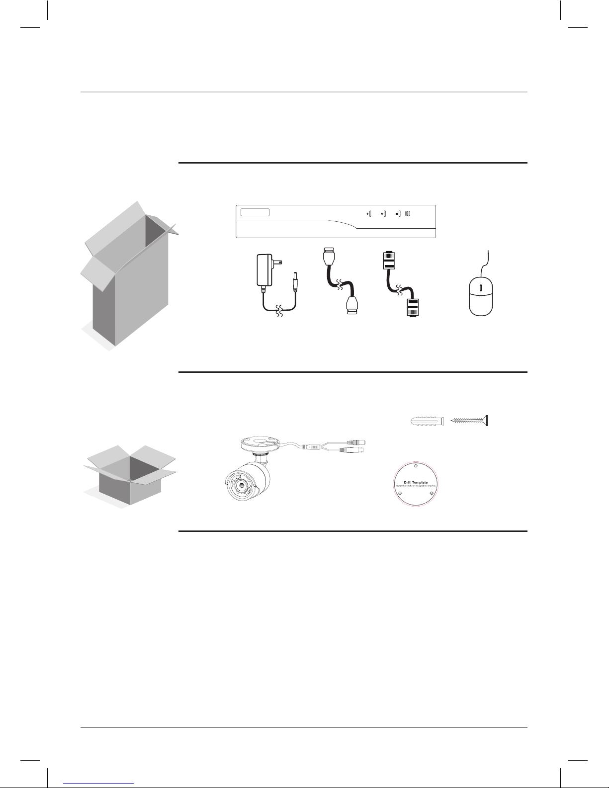
Step 1: Unpack
(4) Camera Boxes
(1) Mounting
Template
(1) Ethernet
Cable
(1) DVR Box
(1) 1TB HDD Digital Video Recorder
(1) Power
Adapter
(1) HDMI
Cable
(1) Mouse
(1) HD Indoor/Outdoor
Security Camera
(3) Mounting Screws
and Anchors
(4) 60ft BNC Cables
(1) Camera Power Splitter
(1) Power Adapter
and this Quick Start Guide
Plus Additional
Cables and
Hardware
3
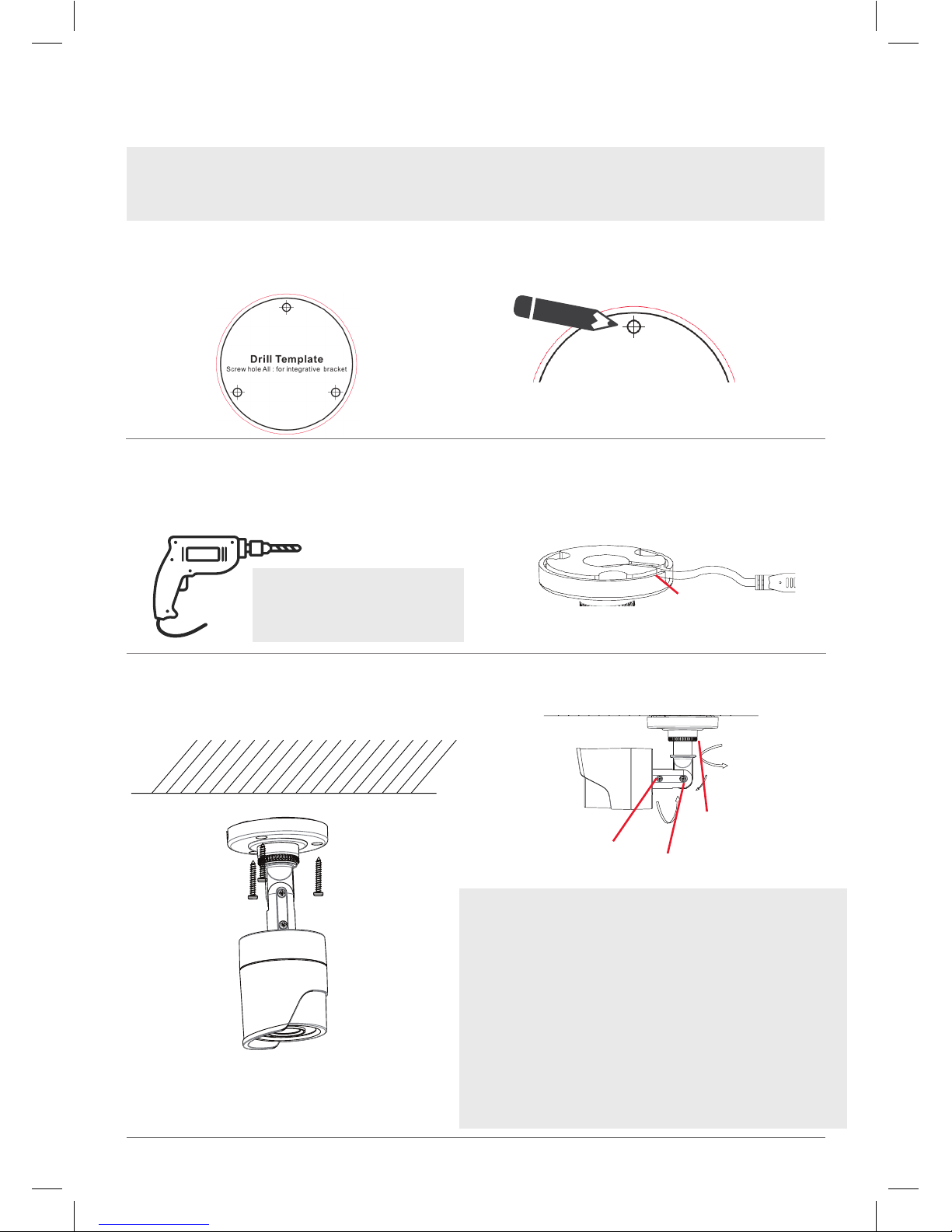
Step 2: Mount the cameras
Note: These security cameras can be both wall- and ceiling-mounted. The installation
instructions that follow are for ceiling mounting, but they can be adapted for wall mounting as
well.
4. Route the cables from the camera
through the cable hole or through the
side outlet on the camera base.
5. Secure the camera to the ceiling or wall
with the supplied screws (and anchors,
for brick or stucco).
For pan adjustment: Loosen the base ring and pan up to
360º. Tighten the base ring when you have the camera
panned the way you want.
For arm tilt adjustment: Loosen the arm screw and tilt the
arm up to 180º. Tighten the screw when you have the arm
in the position you want.
For camera rotation adjustment: Loosen the camera screw
and rotate the camera up to 360º. Tighten the screw when
you have the camera in the position you want.
Make sure the base ring and adjustment screws
are tightened all the way for each camera before
proceeding.
Base ring (pan)
Arm screw (tilt)
Camera screw
(rotation)
1. Apply the mounting template sticker to
the ceiling where you want to mount the
camera.
2. Mark the location for the mounting
holes.
3. Drill screw holes (labeled 1 on the
template) and the cable hole (if desired,
labeled A) where marked.
Use the following drill bit sizes:
brick or stucco = 7/32”
wood surface = 1/16”
Side outlet
7. Adjust the camera’s position to get the
angle you want.
4
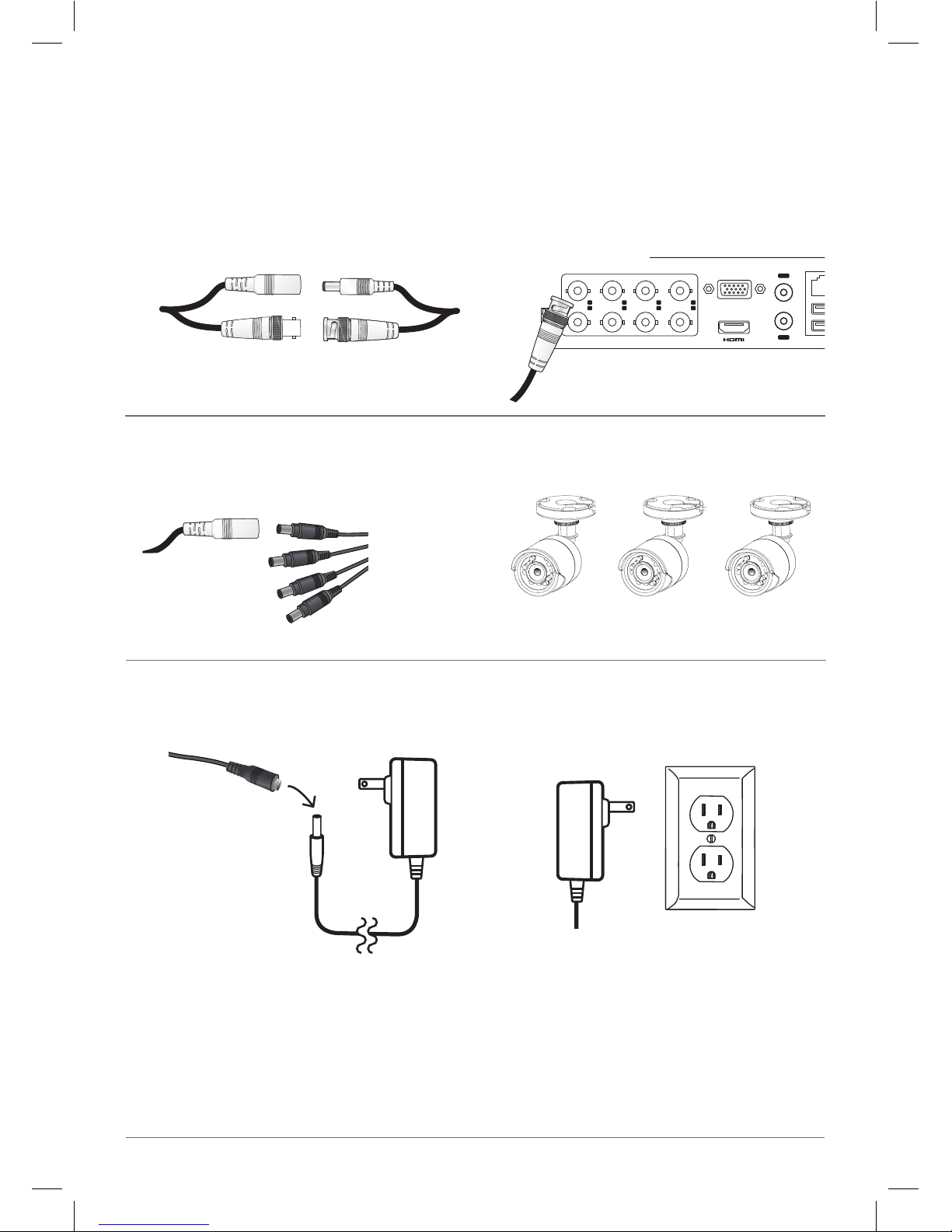
Step 3: Connect cameras to the DVR
1. Find the cables coming from each
camera. Match the video and power
cables to one end of a BNC cable and
connect them.
4. Repeat for the other three cameras.
1
2
3
4
5
6
7
8
VIDEO IN
D+ D-
RS-485
VGA
IN
OUT
AUDIO
LAN&USB 12V
Camera BNC
2. Plug the video output cable on the other
end of this BNC cable into one of the
VIDEO IN jacks on the back of the DVR.
3. Plug the power input cable on the other
end of this BNC cable into the camera
power splitter.
5. Connect the power splitter to the
camera power adapter.
6. Plug the camera power adapter into a
working outlet or surge protector.
DVR back panel
Camera
power
splitter
Camera power
adapter
5
1234567
8
VIDEO IN
VGA
IN
OUT
AUDIO
LAN&USB 12V
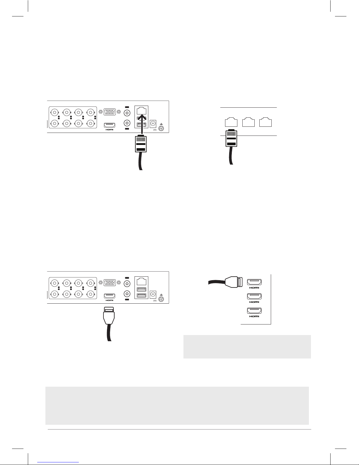
Step 4: Connect the DVR to home network
1234567
8
VIDEO IN
VGA
IN
OUT
AUDIO
LAN&USB 12V
1. Plug one end of the supplied network
cable into the top LAN&USB port on the
back of the DVR.
2. Plug the other end of this network cable
into an open port on the back of your
network router.
Step 5: Connect the DVR to your TV/monitor
1. Plug one end of the supplied HDMI
cable into the HDMI jack on the back of
the DVR.
2. Plug the other end of this HDMI cable
into an open HDMI jack on your TV.
Optional connection: VGA to monitor
You can also connect the DVR to a VGA monitor. Plug one end of a VGA cable (not included)
into the VGA jack on the back of the DVR. Plug the other end into your monitor.
Router
back panel
Note: When you turn the DVR on, you’ll need to use
the INPUT or SOURCE button on your TV’s remote
to tune to the input you plugged the DVR into.
TV

6
Step 6: Power and turn on the DVR
Step 7: Activate your DVR
1. Plug the AC adapter into the 12V jack
on the back of the DVR.
2. The rst time you turn it on, the DVR asks
you to activate the system by creating
an admin password. You must create a
password in the step in order to use the
system.
Click on each eld and use the
on-screen keyboard to enter your
password in the Create New Password
and Conrm New Password elds. Then
click OK to save the password and
activate the device.
1234567
8
VIDEO IN
VGA
IN
OUT
AUDIO
LAN&USB 12V
2. Plug the other end of the adapter into a
working outlet or surge protector.
The
indicator on the front panel
of the DVR is green when the unit is
plugged in. This means the DVR is on!
1. Plug the included mouse into one of the
USB ports on the back of the DVR.
1234567
8
VIDEO IN
VGA
IN
OUT
AUDIO
LAN&USB 12V
IMPORTANT: Make sure your TV or monitor is
tuned to the correct input to view the signal from
the DVR. Also make sure that the
indicator on
the front of the DVR is lit.
IMPORTANT: Make sure you remember your
password! You might want to save it to a USB
drive in the next step, as a physical key in case you
forget.

7
4. Set up a pattern to unlock the device.
Use the mouse to draw the pattern you
want (click to draw, release when you’re
nished).
3. The next screen lets you save your
password to an external USB drive
(like a thumb drive) so that you can
unlock the system if you ever forget the
password.
Note: You must
use at least 4
dots in your
unlock pattern.
Draw the same pattern again to conrm
it.
5. Next, select the language you want to
use for setup and menus on the DVR.
Click Apply to proceed.
6. Select the Start Wizard option and click
Next to launch the Start Wizard.
Continues on the next page...
If you’d like to do this, insert a USB
drive into the available USB port on the
back of the DVR. Then press Yes in the
dialog box shown here and follow the
on-screen instructions to proceed.
Otherwise, click No to continue.

8
Step 8: Follow the Start Wizard steps
1. Click on the Time Zone, Date Format,
System Date, and System Time elds
to make changes. Click on Next when
you’re done.
2. In the next screen, conrm that your
network settings are correct. Then click
Next to continue.
Note: Don’t make changes to this screen unless
you’re certain that you need to!
3. In the next screen, click the box next to
Enable to set up the DVR for use with
the RCA Security App on your phone.
4. The next screen asks you for a
verication code and to agree to the
terms of service.
Click in the Verication Code eld and
use the on-screen keyboard to enter
your verication code.
Then tick the box next to the terms of
service and click OK.
Keep this screen in front of you and go
to the next step to set up the App!

9
Step 9: Download and set up the App
1. In the Google Play or Apple App Stores,
search for “RCA SECURITY” and look
for the icon shown here. Then download
and launch the App.
Minimum Operating System
Requirements for the RCA Security App
• iOS 7 or later
• Android version 4.4 or later
The rst time you launch the RCA Security
App, you’ll need to create a user name and
password so that you can access your camera
securely.
Press the Login button to start, then press
Register on the screen that follows.
2. Register your App and set up your RCA
Security account (if you don’t have one
already).
You can register by mobile phone number or
by email. The App will send you a verication
code to link this number or e-mail address
with your account. Follow the steps in the App
to proceed.
3. Get a verication code for the
App.
4. Create a user name and password and
press Finish.
5. Tap the + symbol in the middle of the
App screen to add the security system.
6. Scan the QR code on your monitor or
TV screen.

10
7. The App will identify your system by this
QR code and show its serial number.
Press the Add button in the App.
8. In the next screen, enter the Verication
Code from the monitor in the App and
press OK in the App.
9. Press Connect to a Network in the next
screen of the App, then choose Wired
Connection.
10. The next screen asks you to conrm
that the DVR is connected to your
router. Press Connected and Next to
continue.
The App starts connecting, then asks you to
enable the RCA Security Service. Press Next
to continue.

11
11. Enter the Admin password you used to
activate the system (see page 6) in the
App to verify the device.
12. When the App is nished adding
the device, it shows you network
information. Press Skip to complete
App setup.

12
Everyday Use
The viewing screen on your monitor or App is the gateway to everyday use of the RCA Security
System. This section gives you a tour of the viewing screen and menus.
Monitor Live View
Each channel oers a live view, with alert/status icons that notify you of what’s going on.
Alarm (video loss, tampering, motion detection, VCA or sensor alarm)
Recording (manual record, continuous record, motion detection, VCA or alarm triggered
record)
Event/Exception (event and exception information, appears at the lower-left corner of the
screen.)
App Live View
The App shows you views for all your active cameras. Press on one
to go to a live view of that camera.
(Back) goes back to the device list screen.
(Timeline / Playback) accesses any content stored on the DVR.
Press this icon to start viewing or downloading motion/soundactivated videos or images.
(Settings) accesses the Settings menu.
Camera view shows you the image from this camera. Turn your
phone/tablet sideways to take over the entire screen.
(Stop) and (Pause) stops/starts or pauses the live video.
(Sound On/O) turns the sound from the camera on and o.
(Zoom) zooms in on the live view.
(Snapshot) takes a still photo of the camera video. The
snapshot le is saved to your smartphone or tablet.
(Record) starts/stops recording video. The video le is saved to
your smartphone or tablet.
1 / 4 / 9 / 12 / 16 (Multi-Camera View) lets you see multiple cameras
at once on a single screen. Press the number you want to access a
multi-camera view screen.

13
Recording Settings
This RCA Security System oers multiple recording options, including Instant Recording, All-Day
Recording, and Motion Detection.
1. Click Start Recording from the rightclick menu.
2. Select Continuous Record or Motion
Detection Record on your demand.
3. Click Yes in the pop-up box to
conrm the settings.
Note: Rebooting the system stops all
manual recordings that are running.
Playback
This RCA Security System oers several ways to play back recorded videos or pictures: instant
playback, all-day playback for a specied channel, and playback by normal/event/smart/tag/
system logs/sub-periods/external le search/picture.
1. Go to Menu > Playback.
2. Check the channel(s) in the channel
list for playback.
3. Double click a date on the calendar.
4. (Optional) Use the toolbar in the
bottom part of Playback interface to
control the playing progress.
5. (Optional) Select the channel(s) to
execute simultaneous playback of
multiple channels.

14
Accessing via Web Browser
This RCA Security System oers access via Web browser as well as through the App and via
connected monitor or TV.
Minimum System Requirements: Internet Explorer 6.0 or later or Apple Safari. Resolutions
1024x768 and above.
1. Right click with the mouse and highlight
Common Menu. Then highlight Network and
choose it.
The Security System will prompt you to draw
your unlock pattern to access this menu. Use
the mouse to draw this pattern (hold to draw,
release when nished).
3. On your computer, open your web browser
and enter the IP address of your device (from
step 2) in the browser’s address eld. Then
press Enter.
4. Log in to the device.
If the device has not been activated, you
need to activate the device rst by setting the
password for the admin user account.
If the device is already activated, enter the
user name and password in the login interface,
and click Login.
5. Install the plug-in before viewing the live video
and managing the camera. Please follow the
installation prompts to install the plug-in.
You may have to close the web browser to
nish the installation of the plug-in.
After login, you can perform the operation and
conguration of the device, including the live
view, playback, log search, conguration, etc.
2. The Conguration screen appears. Make note
of your system’s IP address in the third line on
the left (listed as IPV4). You’ll need to use this
information in the next step.

15

HSKIT482 QSG 02
© 2018 Voxx Accessories Corp.
3502 Woodview Trace, Suite 220
Indianapolis, IN 46268
www.RCAAudioVideo.com
 Loading...