

Page 1

HSFLC1 QSG 03
LIGHTS, CAMERA...
ACTION
QUICK START GUIDE
English instructions .................1
Instructions en français .........13
Instrucciones en español .....25
Page 2
2
WELCOME!
Floodlight
Security
Camera
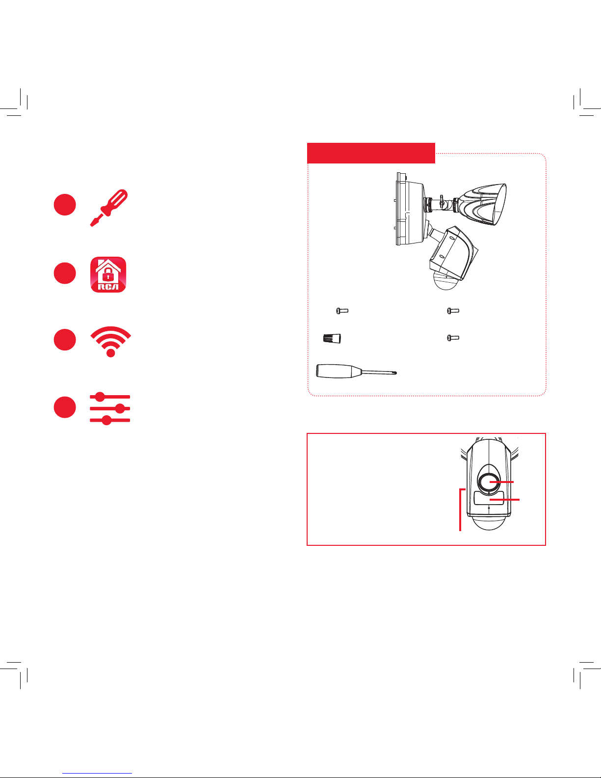
WHAT YOU GET
Installation kit:
1
Mount and connect
the oodlight security
camera
2
Download the RCA
Security App
3
Connect to Wi-Fi
4
Customize your device
settings
(1) Screwdriver
(2) #8x3/8in screws
(3) Wire nuts
(2) #10x3/8in screws
(2) #6x3/8in screws
IMPORTANT
The oodlight camera’s lens,
microphone, and IR sensor have
protective lms covering them when
you rst unpack this product. Make
sure you remove these protective
lms when you’ve nished
mounting the oodlight camera.
Lens
IR
sensor
Microphone
Page 3
3
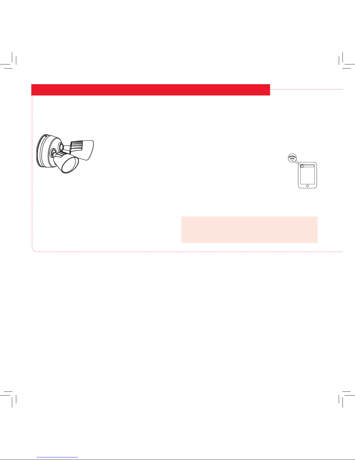
BEFORE YOU START
Test your WiFi signal
Your RCA Floodlight Camera needs a strong enough signal from
your WiFi router in order to send its video signal. Here’s how to
test your WiFi Signal.
First, go to where you want to put the oodlight camera. Make
sure your smartphone or other portable wireless device is
connected to the WiFi network you want to test.
Look at the WiFi icon on your device screen to see
the strength of the connection. For example, on
iOS devices look in the upper left-hand corner of
the screen for the WiFi icon (shown here).
For best results, look for a location with at least
50% strength to use the oodlight camera.
If your WiFi network signal is less than 50% where you want
to install the oodlight camera, a WiFi signal extender is
recommended to boost the signal at the installation point.
IMPORTANT: The RCA Floodlight Camera works with 2.4GHz
WiFi signals. If you have a dual-band router with separate
2.4GHz and 5GHz networks, make sure your phone is
connected to the 2.4GHz one!
IMPORTANT: You must have a junction box
and wiring already installed in order to use
this product.
The RCA Floodlight Camera is
designed to replace an existing
oodlight installation. If you
do not already have a working
oodlight or wired junction box
where you want to install the RCA
Floodlight Camera, consult an
electrician to install one.
Existing Floodlight
Page 4

4
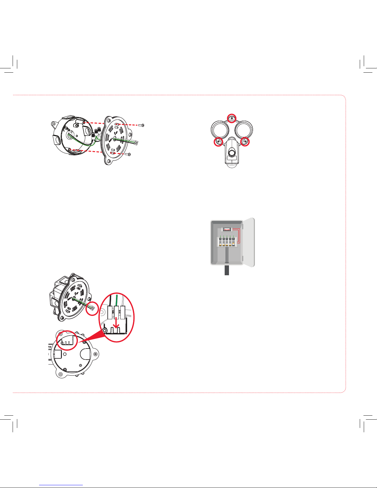
MOUNT AND CONNECT THE FLOODLIGHT CAMERA
Turn off power to your oodlight’s
circuit.
1
Remove your existing oodlight.
2
Connect the junction box and
oodlight camera 3-wire connector.
4
Find the breaker that
controls the circuit for your
oodlight. Turn it off before
you continue installation.
Carefully remove your existing oodlight
from its junction box.
Separate the back/base from the
oodlight camera.
3
Unscrew the 3 base
screws holding the
oodlight camera to the
base (keep these in a
safe place for later).
Pull the oodlight
camera completely off
the base.
Run the wires from
the 3-wire connector
through the oodlight
camera’s base.
Match each color wire
from the oodlight
camera to the same
color from the junction
box (green to green,
white to white, black to
black).
Put the ends of each pair into the three wire
nuts, then twist each nut a full turn to nish.
Existing Floodlight
Floodlight camera, front
Base screws
Turn the oodlight
camera over. Gently
unplug the 3-wire
connector from the
base of the oodlight
camera.
Floodlight camera, bottom
3-wire connector
Page 5
5
Mount the oodlight camera to the
base and junction box.
5
Place each twisted wirenut in the junction
box. Then align the oodlight camera base
on the junction box so that it’s oriented
correctly.
Place 2 #8x1-1/2in screws through the base
and into the the mounting holes on the
junction box. Screw the base rmly in place.
Turn on power to your oodlight’s
circuit
6
Conrm the oodlight camera has
power
7
Turn the breaker that controls
the circuit for your oodlight
back on.
At rst power up, the oodlights come on.
Once the oodlight camera is ready for setup,
the oodlights turn off and the indicator on the
front of the camera ashes blue and red.
Note: If you’ve installed the oodlight camera
on a switchable outlet, make sure you turn the
switch on and leave it on for the oodlight
camera to function 24/7.
Plug the 3-wire connector
back into the oodlight
camera base
as shown.
Make sure it’s
completely
seated before
proceeding.
Place the oodlight
camera over the base so
that the base’s mounting
tabs t into the camera’s
slots. Find the 3 base
screws you removed in
step 3. Put the base screws
back into their slots and
tighten completely.
Floodlight camera, front
Base screws
Page 6
6
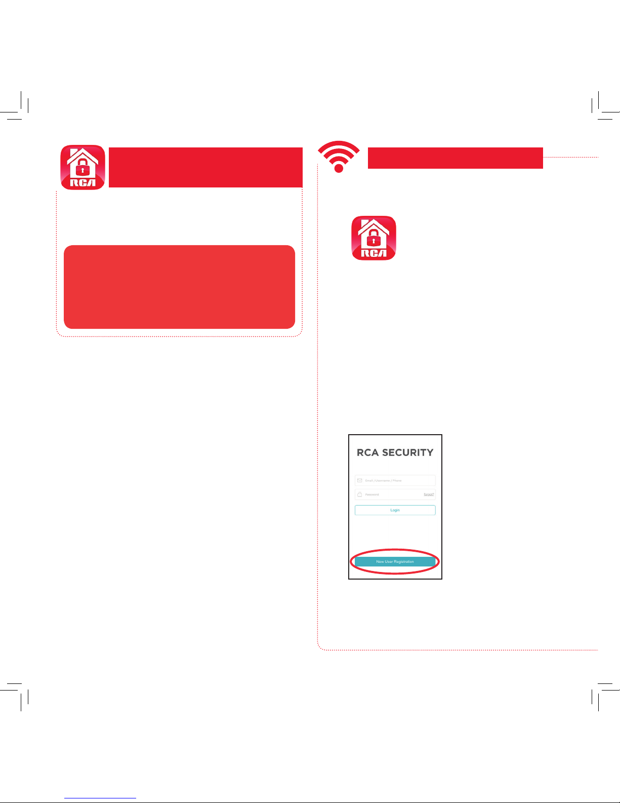
In the Google Play or Apple App Stores, search
for “RCA SECURITY” and look for the icon shown
here. Then download and install the App.
DOWNLOAD THE RCA
SECURITY APP
• iOS 7 or later
• Android version 4.4 or later
Minimum Operating System
Requirements for the RCA Security App
Launch the App
Once the RCA Security App has
installed on your smarphone or
tablet, press the icon to launch
the App.
IMPORTANT: The rst time you
launch it, the App will ask if it
can send you notications. Click
“Allow” to let the App push
notications to your phone or
tablet.
1
Register as a new user
The rst time you launch the RCA Security
App, you’ll need to create a user name and
password so that you can access your camera
securely.
2
Press the New User
Registration button to
get started.
Note: If you already
have an RCA Security
user name and
password enter them in
the appropriate spaces
and press the Login
button.
CONNECT TO WIFI
You can register by mobile phone number or
by email. The App will send you a verication
code to link this number or e-mail address with
your account. Follow the steps in the App to
proceed.
Page 7

7
Enter your email and create a
password, then press Next.
Connect the camera with your WiFi
network
3
In the RCA Security App, tap
the + symbol in the middle of
the screen.
continues on the next page...
Find the QR code and serial
number on the side of the
oodlight camera. Scan the QR
code with your phone when
prompted by the App (or enter
the serial number manually).
Once the App recognizes your
oodlight’s serial number, the App
asks you to connect to your WiFi
network. Tap the Connect to a
Network button in the App.
In the next screen, enter the
password for the WiFi network
your phone is connected to. Then
press the Next button in the App
to proceed.
Floodlight camera, side
QR code
Follow the directions in the App to
perform the following steps:
• copy the oodlight camera’s
password to your phone’s
clipboard for easy access
• go to your phone’s WiFi settings
and connect to the oodlight
camera and enter its password
• return to RCA Security App
and nish connecting to the
oodlight camera
The App will connect to your
oodlight camera and activate it
with your RCA Security account.
Please be patient with your WiFi network! Certain parts of the WiFi
setup, like connecting to your network, could take up to 5-6 minutes
to complete.
Got screen freeze? This is probably due to WiFi activity on your
network, especially if your network has several devices connected to
it. Exit out of the App and start again.
Page 8
8
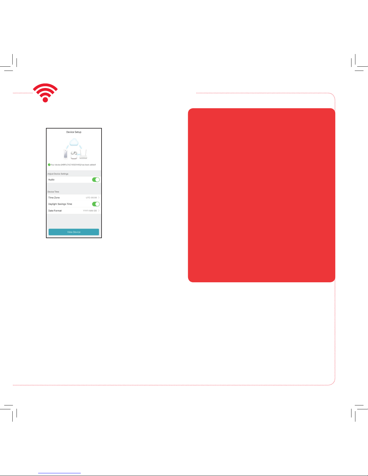
Once the oodlight
camera has nished
connection and activation,
the App will ask for
some nal information
to complete setup,
such as your time zone
and whether you want
audio to be on by
default. Once you’ve
nished customizing
these settings, press the
View Device button to
continue.
Finish setup
4
CONNECT TO WIFI (continued)
+ Make sure that WiFi signal is 2.4GHz. The RCA
Floodlight Camera does not support 5GHz WiFi.
+ Make sure your phone or tablet is connected to the
WiFi network you want to use (2.4GHz if your network
offers separate networks for each band).
+ Make sure the camera is getting a good signal from
your WiFi router.
+ Test your WiFi network with other devices to make sure
it’s working.
+ Double check that you’ve entered the correct password
for your WiFi network in the App.
+ Make sure that your WiFi router uses either WPA2-PSK/
WPA-PSK or AES as its encryption method.
+ Make sure that there is no MAC lter on router or add
MAC address to router whitelist.
+ Reset the camera to set up connection again. Open
the door on the side of the camera using the included
screwdriver. Find the RESET key under this door.
Press and hold RESET key for 15 seconds. The camera
announces when it is fully reset (rebooting).
Connection Troubleshooting
For additional assistance, please call
1-833-236-6561.
Page 9
9
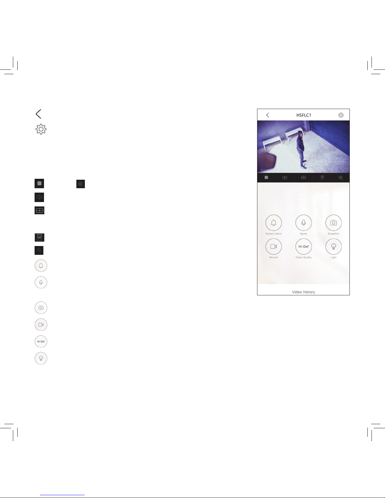
(Back) goes back to the device list screen.
(Settings) accesses the Settings menu for this camera. Press this
icon to turn motion alarms on or off, adjust camera audio, check storage
status and the version of the device’s software, adjust the time and date
settings, and more.
Camera view shows you the image from your Floodlight Camera. Turn
your phone/tablet sideways to take over the entire screen.
(Stop) and (Pause) stops/starts or pauses the live video.
(Sound On/Off) turns the sound from the camera on and off.
(Multi-Camera View) lets you see multiple cameras at once on a
single screen (if you’ve set up multiple cameras). Press the number you
want to access a multi-camera view screen.
(Flip) ips the orientation of the camera view to facilitate viewing.
(Zoom) zooms in on the live view.
(Alarm) turns the 110db siren alarm on and off.
(Talk) lets you speak through this camera’s built-in speaker. Press this
icon to start speaking.
TOUR OF THE SYSTEM: LIVE VIEW SCREEN
(Snapshot) takes a still photo of the camera video. The snapshot le is saved to your smartphone or tablet.
(Record) starts/stops recording video. The video le is saved to your smartphone or tablet.
(Video Quality) lets you switch between high- and standard-denition video on the view screen.
(Light control) turns the oodlights off and on.
Video History accesses the oodlight camera’s timeline, allowing you to access recordings stored on the
oodlight camera’s memory card by the times they occurred.
Page 10
10
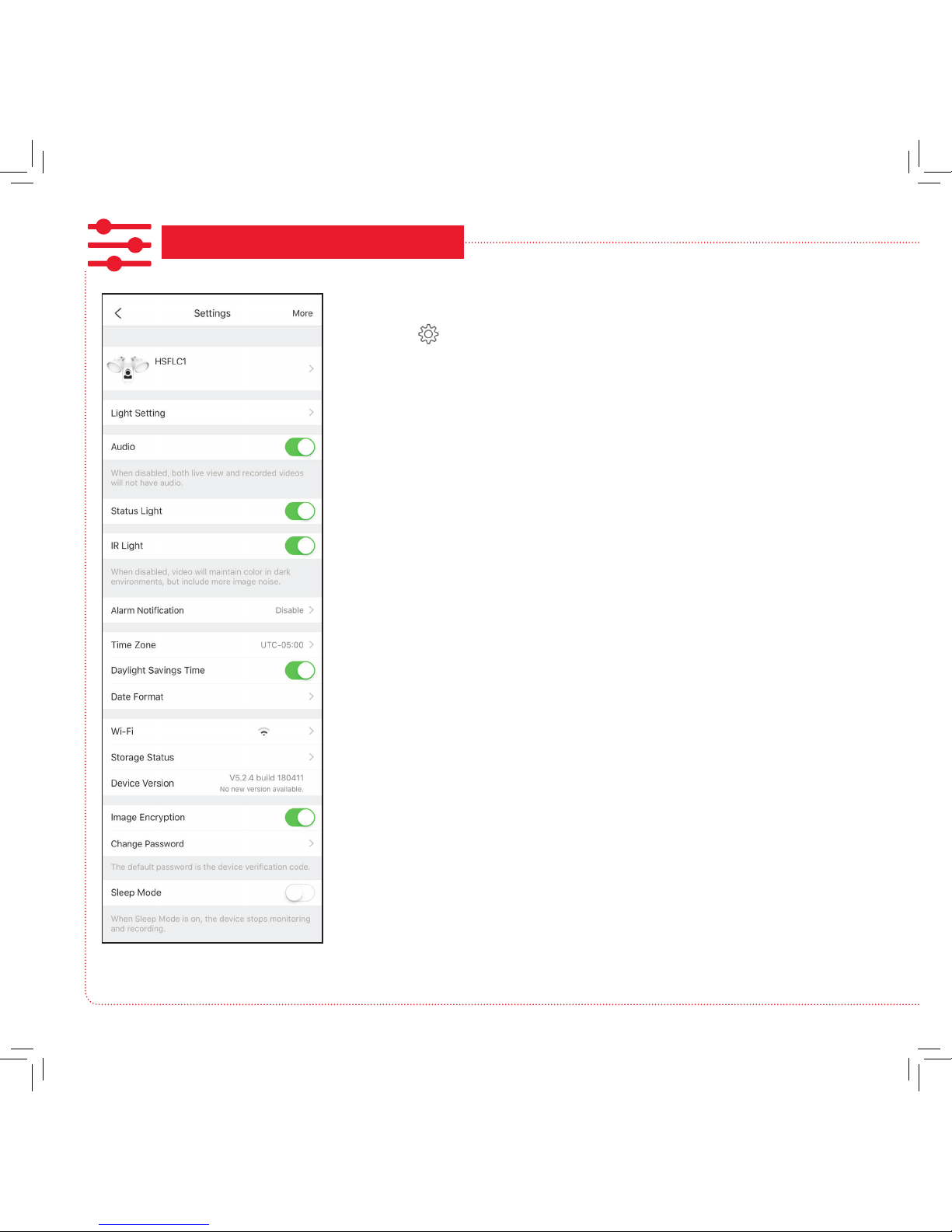
CUSTOMIZE AND USE!
Using the Settings Menu
Press the icon in the Live View screen to access the following
customizable parameters of your oodlight camera.
Light Setting lets you adjust the brightness of the oodlight and enable
motion detection (Light Linkage) for the lights, including setting the areas
of the camera’s vision where motion detection is active.
Audio turns audio on/off for recording and live viewing.
Status Light turns the camera’s indicator light on/off.
IR Light turns the camera’s night vision feature on/off.
Alarm Notication lets you set notication schedules for when you want
to receive alerts. Also lets you set the motion detection area for alerts and
the detection sensitivity, as well as the sound the oodlight camera makes
when motion is detected.
Time Zone, Daylight Savings Time, and Date Format let you adjust the
time zone, daylight savings time, and date format settings you made during
setup.
Wi-Fi lets you change WiFi network information for your oodlight camera
and keep the device active on the new network. This is a convenient option
if you get a new wireless router, for example.
Storage Status lets you format the inserted memory card. A dot next to this
item in the menu means that the SD card requires attention.
Device Version shows you the rmware version of the oodlight camera. A
dot next to this item in the menu means that a rmware update is available.
Choose this option and following the instructions to update.
Image Encryption increases the security of the video from the oodlight
camera. This option is on by default.
Change Password lets you change the oodlight camera’s device
password (not your WiFi password). The default password is the verication
code next to the QR code on the side of the camera.
Sleep Mode lets you put the oodlight camera to sleep. The App will
prompt you to wake the oodlight camera again when you try to view it in
the Live View screen.
Page 11
11
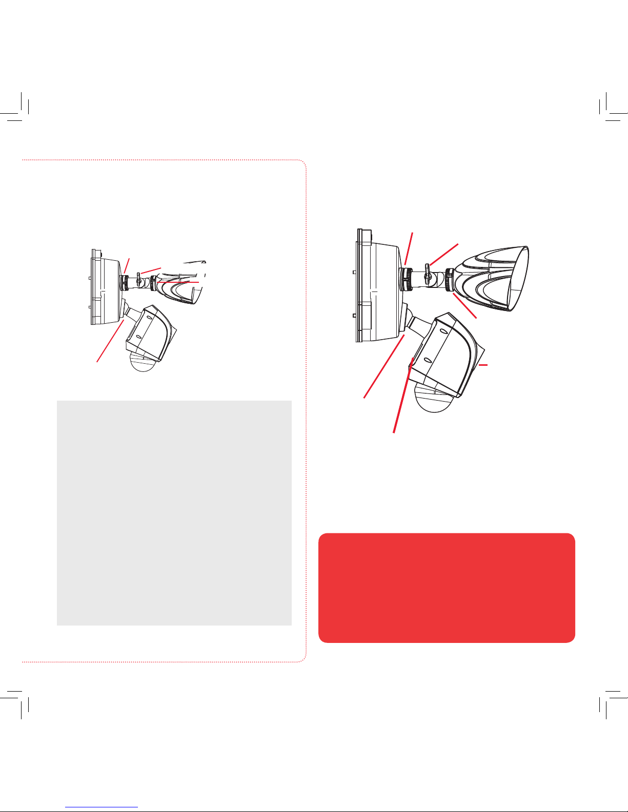
TOUR OF THE
FLOODLIGHT CAMERA
Light base ring (pan)
Light arm screw (tilt)
Camera arm
and ball-joint
Base
Floodlight
Camera
Your oodlight camera comes with a Micro-SD card pre-installed,
for recording alerts. This SD card is installed in a slot behind a door
on the underside of the camera. To remove or replace this card, use
the included screwdriver to unscrew the door on the side of the
camera open. Press the installed SD card to unlock it and pull it out.
Place the new SD card in and lock it into place. Then place the door
cover back on.
Removing/Replacing the SD Card
SD card and Reset button
(behind the door)
Lens
Position the camera and lights.
Lights
For pan adjustment: Loosen the base ring and
pan up to 360º. Tighten the base ring when you
have the light panned the way you want.
For arm tilt adjustment: Loosen the arm screw and
tilt the arm up to 180º. Tighten the screw when
you have the arm in the position you want.
For rotation adjustment: Loosen the light screw
and rotate the light up to 360º. Tighten the screw
when you have the light in the position you want.
Camera
Move the camera arm in its ball joint until you
have the camera in the position you want.
Make sure the base ring and adjustment
screws are tightened all the way for each
camera before proceeding.
Light base ring (pan)
Light arm screw (tilt)
Light screw (rotation)
Adjust the position of the camera and lights to get
the angle you want.
Camera arm
and ball-joint
Light screw
(rotation)
Page 12

12
QUESTIONS?
CALL US! 1-833-236-6561
weekdays 8am-6pm Eastern
E-MAIL US! support@voxxintl.zendesk.com
Page 13

13
English instructions .................1
Instructions en français .........13
Instrucciones en español .....25
PROJECTEURS, CAMÉRA...
ACTION
GUIDE DE
DÉMARRAGE RAPIDE
Page 14

14
BIENVENUE!
Caméra de
sécurité avec
projecteurs
CE DONT VOUS DISPOSEZ
Kit d’installation :
(2) Vis n°6 x 3/8 po
1
Monter et connecter
la caméra de sécurité
avec projecteurs
2
Télécharger l’application
RCA Security
3
Se connecter au Wi-Fi
4
Personnaliser les paramètres
de votre appareil
(1) Tournevis
(2) Vis n°8 x 3/8 po
(3) Raccords de ls (2) Vis n°10 x 3/8 po
IMPORTANT
L’objectif, le microphone et le
capteur infrarouge de la caméra
avec projecteurs sont protégés
par des lms de protection lors du
premier déballage de ce produit.
S’assurer de retirer ces lms de
protection lorsque la caméra
avec projecteurs est assemblée.
Objectif
Capteur
IR
Microphone
Page 15

15
AVANT DE COMMENCER
Tester le signal WiFi
Votre caméra RCA avec projecteurs a besoin d’un signal sufsamment
fort de votre routeur WiFi pour envoyer son signal vidéo. Voici
comment tester le signal WiFi.
Tout d’abord, se rendre à l’endroit où la caméra avec projecteurs
doit être placée. Vérier que le téléphone intelligent ou autre
périphérique sans l portatif est connecté au réseau WiFi qui doit être
testé.
Regarder l’icône WiFi sur l’écran de l’appareil pour
voir l’intensité de la connexion. Par exemple, sur les
appareils iOS, rechercher l’icône WiFi dans le coin
supérieur gauche de l’écran (illustré ci-contre).
Pour de meilleurs résultats, rechercher un
emplacement avec au moins 50 % d’intensité
pour utiliser la caméra avec projecteurs.
Si le signal de votre réseau WiFi est inférieur à 50 % à l’endroit
où la caméra doit être installée, un extenseur de signal WiFi est
recommandé pour amplier le signal au point d’installation.
IMPORTANT : La caméra RCA avec projecteurs fonctionne avec
les signaux WiFi 2,4 GHz. Si un routeur à deux bandes est utilisé,
avec des réseaux séparés 2,4 GHz et 5 GHz, s’assurer que le
téléphone est connecté au 2,4 GHz!
IMPORTANT : Une boîte de connexion et
un câblage déjà installés sont nécessaires
pour pouvoir utiliser ce produit.
La caméra RCA avec projecteurs
est conçue pour remplacer
une installation de projecteurs
existante. S’il n’y a pas de projecteur
opérationnel ni de boîte de
connexion câblée à l’endroit où
la caméra RCA avec projecteurs
doit être installée, consulter un
électricien pour installer une
boîte de connexion.
Projecteurs existants
Page 16

16
MONTER ET CONNECTER LA CAMÉRA AVEC PROJECTEURS
Couper l’alimentation du circuit des
projecteurs existants.
1
Retirer les projecteurs existants.
2
Connecter la boîte de connexion et
connecteur à 3 ls de la caméra avec
projecteurs.
4
Repérer le disjoncteur qui
commande le circuit des
projecteurs. Le désactiver
avant de continuer
l’installation.
Avec précaution, retirer les projecteurs existants
de la boîte de connexion.
Mettre les extrémités de chaque paire de ls dans les
trois raccords, puis tourner chaque raccord d’un tour
complet pour terminer.
Projecteurs existants
Séparer l’arrière/la base de la caméra
avec projecteurs.
3
Dévisser les 3 vis qui xent
la caméra avec projecteurs
à la base (les garder dans
un endroit sûr pour une
utilisation ultérieure).
Caméra avec projecteurs,
vis avant de la base
Retirer complètement la
caméra avec projecteurs
de sa base.
Retourner la caméra avec
projecteurs. Débrancher
délicatement le
connecteur à 3 ls de la
base de la caméra.
Caméra avec projecteurs,
connecteur inférieur à 3 ls
Faire passer les ls du
connecteur à 3 ls à
travers la base de la
caméra.
Faire correspondre
chaque l de couleur
de la caméra à la même
couleur depuis la boîte
de connexion (vert à
vert, blanc à blanc, noir
à noir).
Page 17

17
Monter la caméra avec projecteurs sur
la base et la boîte de connexion.
5
Rétablir l’alimentation du circuit des
projecteurs.
6
Conrmer que la caméra avec
projecteurs est alimentée.
7
Réactiver le disjoncteur qui
commande le circuit des
projecteurs.
Placer chaque raccord torsadé dans la boîte de
connexion. Aligner ensuite la base de la caméra
avec projecteurs sur la boîte de jonction pour
qu’elle soit orientée correctement.
Placer 2 vis # 8 x 1-1/2 po à travers la base et dans
les trous de montage de la boîte de jonction.
Visser la base fermement en place.
Brancher le connecteur à 3
ls dans la base de la caméra
avec projecteurs
comme indiqué.
S’assurer qu’il est
complètement
enfoncé avant de
continuer.
À la première mise sous tension, les projecteurs
s’allument. Une fois que la caméra avec projecteurs
est prête pour la conguration, les projecteurs
s’éteignent et l’indicateur sur le devant de la caméra
clignote en bleu et en rouge.
Remarque : Si la caméra avec projecteurs est
installée sur une prise commutable, s’assurer d’activer
l’interrupteur et de le laisser activé pour que la
caméra avec projecteurs fonctionne 24 heures sur 24
et 7 jours sur 7.
Placer la caméra avec projecteurs
sur la base de telle manière que
les pattes de montage de la base
s’insèrent dans les encoches de
la caméra. Récupérer les 3 vis de
la base qui ont été retirées au
cours de l’étape 3. Placer les vis
de la base dans leurs logements
et serrer complètement.
Caméra avec projecteurs,
vis avant de la base
Page 18

18
Dans les magasins Google Play ou Apple App,
rechercher « RCA SECURITY » et rechercher l’icône
illustrée ci-contre. Ensuite, télécharger et installer
l’application.
TÉLÉCHARGER
L’APPLICATION
RCA SECURITY
• iOS 7 ou une version ultérieure
• Android version 4.4 ou ultérieure
Conguration minimale du système
d’exploitation pour l’application de
sécurité RCA
Lancer l’application
Une fois que l’application RCA
Security est installée sur le téléphone
portable ou la tablette, appuyer sur
l’icône pour lancer l’application.
IMPORTANT : La première fois
qu’elle est lancée, l’application
demande si elle peut vous envoyer
des notications. Cliquer sur « Allow »
(Autoriser) pour permettre les
notications push de l’application
sur votre téléphone ou votre tablette.
1
2
L’inscription peut être faite par téléphone mobile ou
par courrier électronique. L’application envoie un
code de vérication pour relier ce numéro ou votre
adresse de courrier électronique à votre compte.
Suivre les étapes dans l’application pour continuer.
CONNEXION AU WIFI
S’inscrire en tant que nouvel utilisateur
La première fois que l’application RCA Security est
lancée, un nom d’utilisateur et un mot de passe
doivent être créés an de pouvoir accéder à la
caméra en toute sécurité.
Appuyer sur le bouton
New User Registration
(Inscription d’un
nouvel utilisateur) pour
commencer.
Remarque : Si vous
disposez déjà d’un nom
d’utilisateur et d’un mot
de passe RCA Security,
les saisir dans les espaces
appropriés et appuyer
sur le bouton Login
(Connexion).
Page 19

19
Connecter la caméra au réseau WiFi
3
Dans l’application RCA Security,
appuyer sur le symbole + au
milieu de l’écran.
Suite à la page suivante…
Repérer le code QR et le numéro
de série sur le côté de la caméra
avec projecteurs. Balayer le code
QR avec le téléphone lorsque
l’application vous invite à le faire
(ou saisir le numéro de série
manuellement).
Une fois que l’application reconnaît le
numéro de série de votre caméra avec
projecteurs, elle vous invite à vous
connecter au réseau WiFi. Appuyer
sur le bouton Connect to a Network
(Se connecter à un réseau) dans
l’application.
Saisir votre adresse courriel et
créer un mot de passe, puis
appuyer sur Next (Suivant).
Caméra avec projecteurs,
code QR sur le côté
Dans l’écran suivant, saisir le mot de
passe pour le réseau WiFi auquel le
téléphone est connecté. Appuyer
sur le bouton Next (Suivant) dans
l’application pour continuer.
Suivre les instructions de l’application
pour réaliser les étapes suivantes :
• copier le mot de passe de la caméra
avec projecteurs dans le presse-
papiers du téléphone pour faciliter
l’accès
• se rendre dans les paramètres WiFi
du téléphone, se connecter à la
caméra avec projecteurs et saisir
son mot de passe
• retourner à l’application RCA
Security et terminer le processus
de connexion à la caméra avec
projecteurs
L’application se connectera à votre
caméra avec projecteurs et l’activera
avec votre compte RCA Security.
Soyez patient avec votre réseau WiFi! Certaines parties de la
conguration WiFi, comme la connexion à votre réseau, peuvent
prendre entre 5 et 6 minutes.
Votre écran est gelé? Ceci est probablement dû à l’activité WiFi sur
votre réseau, en particulier si votre réseau est connecté à plusieurs
périphériques. Quitter l’application et recommencer.
Page 20

20
CONNEXION AU WIFI (suite)
+ Vérier que le signal WiFi est de 2,4 GHz. La caméra RCA
avec projecteurs ne prend pas en charge le WiFi 5 GHz.
+ S’assurer que son téléphone ou sa tablette est connecté(e)
au réseau WiFi souhaité (2,4 GHz si le réseau offre des
réseaux distincts pour chaque bande).
+ Vérier que la caméra reçoit un bon signal du routeur WiFi.
+ Tester le réseau WiFi avec d’autres appareils pour s’assurer
de son fonctionnement.
+ Vérier que le mot de passe correct pour le réseau WiFi
considéré a été saisi dans l’application.
+ Vérier que le routeur WiFi utilise WPA2-PSK / WPA-PSK
ou AES comme méthode de cryptage.
+ Vérier qu’il n’y a pas de ltre MAC sur le routeur ou
ajouter une adresse MAC à la liste blanche du routeur.
+ Réinitialiser la caméra pour recongurer la connexion.
Ouvrir le couvercle sur le côté de la caméra grâce au
tournevis inclus. Repérer la touche RESET (Réinitialisation)
derrière ce couvercle. Appuyer sur la touche RESET
(Réinitialisation) et la maintenir enfoncée pendant 15
secondes. La caméra annonce lorsqu’elle est complètement
réinitialisée (redémarrage).
Dépannage de la connexion
Pour toute assistance supplémentaire,
composer le 1-833-236-6561.
Une fois la connexion et
l’activation de la caméra
avec projecteurs terminées,
l’application demande des
informations nales pour
terminer la conguration,
comme le fuseau horaire
et si l’audio doit être activé
par défaut. Une fois que
la personnalisation de ces
paramètres est terminée,
appuyer sur le bouton View
Device (Afcher l’appareil)
pour continuer.
Terminer la conguration
4
Page 21

21
(Retour) revient à l’écran de la liste des périphériques.
(Paramètres) permet d’accéder au menu Paramètres de cette caméra. Appuyer
sur cette icône pour activer ou désactiver les alarmes de mouvement, régler le son de
la caméra, vérier l’état du stockage et la version du logiciel de l’appareil, régler les
paramètres de l’heure et de la date, etc.
Afchage de la caméra montre l’image transmise par la caméra avec projecteurs. Mettre
le téléphone / la tablette sur le côté pour prendre en
charge l’écran entier.
(Arrêt) et (Pause) permet d’arrêter/démarrer ou de mettre en pause
la vidéo en direct.
(Son activé/désactivé) permet d’activer ou de désactiver le son en provenance
de la caméra.
(Vue multi-caméras) permet d’afcher plusieurs caméras à la fois sur un seul écran
(si plusieurs caméras sont congurées). Appuyer sur le nombre de caméras auxquelles
il est souhaité d’accéder sur un écran de vue multi-caméras.
(Retourner) change l’orientation de l’afchage de la caméra pour faciliter la
visualisation.
(Zoom) permet de zoomer sur la vue en direct.
(Alarme) permet d’activer ou de désactiver la sirène.
(Parler) permet de communiquer via le haut-parleur intégré de cette caméra.
Appuyer sur cette icône pour commencer à parler.
(Instantané) permet de prendre une photo xe de la vidéo de la caméra. Le chier
de l’instantané est enregistré sur votre téléphone intelligent
ou votre tablette.
(Enregistrement) permet de démarrer/arrêter l’enregistrement vidéo. Le chier
vidéo est enregistré sur votre téléphone intelligent ou votre tablette.
(Qualité vidéo) permet de basculer entre des vidéos haute dénition et standard
sur l’écran d’afchage.
(Commande de la lumière) permet d’activer ou de désactiver les projecteurs.
Video History (Historique vidéo) donne accès à la chronologie de la caméra avec
projecteurs, ce qui vous permet d’accéder aux enregistrements stockés sur la carte
mémoire de la caméra avec projecteurs selon l’heure à laquelle ils se sont produits.
PRÉSENTATION DU SYSTÈME : ÉCRAN VUE EN DIRECT
Page 22

22
PERSONNALISER ET UTILISER!
Utilisation du menu paramètres
Appuyer sur l’icône dans l’écran Live View (Vue en direct) pour accéder aux
paramètres personnalisables suivants de la caméra avec projecteurs.
Light Setting (Réglage lumière) vous permet d’ajuster la luminosité du projecteur
et d’activer la détection de mouvement (Light Linkage - Association à la luminosité)
pour les lumières, y compris le réglage des zones de vision de la caméra où la
détection de mouvement est active.
Audio active / désactive l’audio pour l’enregistrement et la visualisation en direct.
Status Light (Indicateur d’état) permet d’activer et désactiver le voyant de la
caméra.
IR Light (Indicateur d’état) permet d’activer et désactiver la fonction de vision infra-
rouge de la caméra.
Alarm Notication (Notication d’alarme) permet de planier les moments
souhaités pour recevoir des notications d’alertes. Permet également de dénir
la zone de détection de mouvement pour les alertes et la sensibilité de détection,
ainsi que le son produit par la caméra avec projecteurs lorsqu’un mouvement est
détecté.
Time Zone (Fuseau horaire), Daylight Savings Time (Heure d’été) et Date Format
(Format de date) permettent d’ajuster les paramètres de fuseau horaire, d’heure
d’été et de format de date que vous avez dénis lors de la conguration.
Wi-Fi permet de modier les informations de réseau WiFi pour la caméra avec
projecteurs et de garder l’appareil actif sur le nouveau réseau. C’est une option
pratique si un nouveau routeur sans l est utilisé, par exemple.
Storage Status (État de stockage) vous permet de formater la carte mémoire
insérée. Un point à côté de cet élément dans le menu signie que la carte SD
nécessite une attention particulière.
Device Version (Version de l’appareil) afche la version du micrologiciel de la
caméra avec projecteurs. Un point à côté de cet élément dans le menu signie
qu’une mise à jour du micrologiciel est disponible. Choisir cette option et suivre les
instructions pour le mettre à jour.
Image Encryption (Cryptage de l’image) augmente la sécurité de la vidéo de la
caméra avec projecteurs. Cette option est activée par défaut.
Change Password (Modication du mot de passe) permet de modier le mot de
passe de la caméra avec projecteurs (non pas votre mot de passe WiFi). Le mot de
passe par défaut est le code de vérication indiqué à côté du code QR sur le côté
de la caméra.
Sleep Mode (Mode veille) permet de mettre la caméra avec projecteurs en veille.
L’application invite à réactiver la caméra avec projecteurs lorsqu’on essaie de
l’afcher dans l’écran Live View (Vue en direct).
Page 23

23
PRÉSENTATION DE LA
CAMÉRA AVEC PROJECTEURS
Anneau sur la base des lampes (panoramique)
Vis sur le bras (inclinaison)
Vis sur la lampe (rotation)
Bras et rotule
de la caméra
Base
Projecteur
Caméra
La caméra avec projecteurs est équipée d’une carte Micro-SD
préinstallée, pour l’enregistrement des alarmes. Cette carte SD
est installée dans une fente derrière un couvercle sur le dessous
de la caméra. Pour retirer ou remplacer cette carte, utiliser le
tournevis inclus pour dévisser et ouvrir le couvercle situé sur
le côté de la caméra. Appuyer sur la carte SD installée pour
la déverrouiller et la retirer. Placer la nouvelle carte SD et la
verrouiller en place. Puis remettre le couvercle en place.
Retrait / Remplacement de la carte SD
Carte SD et bouton de réinitialisation
(derrière le couvercle)
Objectif
Positionnement de la caméra et des lampes.
Lampes
Pour le réglage panoramique : Desserrer l’anneau sur la
base et régler jusqu’à 360°. Resserrer l’anneau sur la base
une fois la lumière positionnée comme souhaité.
Pour le réglage de l’inclinaison du bras : Desserrer la vis
du bras et incliner le bras jusqu’à 180°. Resserrer la vis une
fois le bras positionné comme souhaité.
Pour le réglage de la rotation : Desserrer la vis de la lampe
et tourner la lampe jusqu’à 360°. Resserrer la vis une fois
la lampe positionnée comme souhaité.
Caméra
Déplacer le bras de la caméra dans sa rotule jusqu’à ce
que la caméra soit dans la position souhaitée.
Vérier que l’anneau sur la base et les vis de
réglage de chaque caméra sont bien serrés avant de
poursuivre.
Anneau sur la base des lampes (panoramique)
Vis sur le bras (inclinaison)
Vis sur la lampe (rotation)
Régler la position de la caméra et des lampes pour
obtenir l’angle souhaité.
Bras et rotule
de la caméra
Page 24

24
DES QUESTIONS?
COMMUNIQUEZ AVEC NOUS! 1-833-236-6561 en semaine 8h-18h, fuseau horaire de l’Est
ENVOYEZ-NOUS UN COURRIEL! support@voxxintl.zendesk.com
Page 25

25
English instructions .................1
Instructions en français .........13
Instrucciones en español .....25
LUCES, CÁMARA…
ACCIÓN
GUÍA DE
INICIO RÁPIDO
Page 26

26
¡BIENVENIDO!
Cámara de
seguridad con
proyector
LO QUE USTED RECIBE
Juego de instalación:
(2) Tornillos
6 x 3/8 pulgada
1
Monte y conecte la cámara
de seguridad con proyector
2
Descargue la RCA Security
App (Aplicación de
seguridad RCA)
3
Conecte a WiFi
4
Personalice los ajustes de
su dispositivo
(1) Destornillador
(2) Tornillos
8 x 3/8 pulgada
(3) Tuercas para alambre
(2) Tornillos
10 x 3/8 pulgada
IMPORTANTE
La lente, el micrófono y el sensor
IR de la cámara con proyector
están cubiertos con películas
protectoras cuando los desempaca
por primera vez. Asegúrese de
quitar estas películas protectoras
cuando haya terminado de montar
la cámara con proyector.
Lente
Sensor
IR
Micrófono
Page 27

27
ANTES DE COMENZAR
Pruebe su señal WiFi
La cámara con proyector RCA necesita una señal sucientemente
intensa de su enrutador WiFi para transmitir la señal de video.
Siga estos pasos para probar su señal WiFi.
Primero, vaya donde usted quiere colocar la cámara con proyector.
Asegúrese que su teléfono inteligente u otro dispositivo inalámbrico
portátil estén conectados a la red WiFi que usted desea probar.
Observe el icono WiFi en la pantalla de su dispositivo
para ver la intensidad de la conexión. Por ejemplo,
en los dispositivos iOS fíjese en la esquina superior
izquierda de la pantalla para ver el icono WiFi
(mostrado aquí).
Para obtener los mejores resultados, busque un lugar
con una intensidad del 50% como mínimo para usar
la cámara con proyector.
Si la señal de la red WiFi no llega al 50% en el lugar donde quiere
instalar la cámara con proyector, se recomienda un extensor de
señal WiFi para reforzar la señal en el punto de instalación.
IMPORTANTE: La cámara con proyector RCA funciona con
señales WiFi de 2.4 GHz. Si usted tiene un enrutador de banda
doble con redes separadas de 2.4 GHz y 5 GHz, ¡asegúrese que
su teléfono esté conectado a la red de 2.4 GHz!
IMPORTANTE: Debe tener una caja de
conexiones con cableado ya instalada
para poder utilizar este producto.
La cámara con proyector RCA está
diseñada para reemplazar una
instalación de iluminación con
proyectores existente. Si no tiene un
proyector que funcione o una caja
de conexiones cableada en el lugar
donde quiere instalar la cámara con
proyector RCA, consulte con un
electricista para que instale una.
Proyector existente
Page 28

28
MONTE Y CONECTE LA CÁMARA CON PROYECTOR
Apague la alimentación eléctrica para el
circuito del proyector.
1
Retire el proyector existente.
2
Conecte la caja de conexiones y conector
de 3 cables de la cámara con proyector.
4
Encuentre el cortacircuito que
controla el circuito para su
proyector. Desconéctelo
antes de continuar con
la instalación.
Extraiga cuidadosamente su proyector existente
de su caja de conexiones.
Separe la parte posterior/base de la
cámara con proyector.
3
Ponga los extremos de cada par en las tres tuercas
para cable y luego gire cada tuerca una vuelta
completa para terminar.
Proyector existente
Desatornille los 3 tornillos
de la base que sujetan la
cámara con proyector a
esta (guarde los tornillos
en un lugar seguro para
más tarde).
Cámara con proyector, tornillos
en la parte anterior de la base
Separe la cámara con
proyector completamente
de la base.
Voltee la cámara con
proyector. Desconecte
con cuidado el conector
de 3 cables de la base de
la cámara con proyector.
Cámara con proyector,
conector inferior de 3 cables
Pase los cables desde el
conector de 3 cables a
través de la base de la
cámara con proyector.
Empareje cada cable
de color de la cámara
con proyector con el
mismo color de la caja
de conexiones (verde
con verde, blanco con
blanco, negro con
negro).
Page 29

29
Monte la cámara con proyector a la
base y la caja de conexiones.
5
Encienda la alimentación eléctrica para
el circuito de su proyector.
6
Conrme que la cámara con proyector
recibe alimentación eléctrica.
7
Vuelva a encender el
cortacircuito que controla el
circuito para su proyector.
Coloque cada tuerca para alambre girada en la
caja de conexiones. Luego alinee la base de la
cámara con proyector sobre la caja de conexiones
de manera que quede orientada correctamente.
Coloque 2 tornillos 8x1-1/2 pulg. a través de la
base en los oricios de montaje de la caja de
conexiones. Enrosque la base rmemente en su
lugar.
Conecte el conector de 3
cables de nuevo en la base de
la cámara con
proyector, tal
como se muestra.
Asegúrese
que esté
completamente
asentado antes
de proceder.
Al encenderla por primera vez, los proyectores se
encienden. Una vez que la cámara con proyector
esté lista para congurarse, los proyectores se
apagan y el indicador en la parte anterior de la
cámara parpadea en azul y rojo.
Aviso: Si ha instalado la cámara con proyector
en un tomacorriente conmutable, asegúrese
de activarlo (en posición encendido) y dejarlo
activado para que la cámara con proyector pueda
funcionar 24/7.
Coloque la cámara con proyector
sobre la base de manera que
las lengüetas de montaje de la
base encajen en las ranuras de la
cámara. Encuentre los 3 tornillos
de la base que retiró en el paso
3. Ponga los tornillos de la base
de nuevo en sus ranuras y apriete
completamente.
Cámara con proyector,
tornillos en la parte anterior
de la base
Page 30

30
En las tiendas Google Play o Apple App, busque “RCA
SECURITY” y el icono mostrado aquí. Luego, descargue
e instale la aplicación.
DESCARGUE LA RCA
SECURITY APP (APLICACIÓN
DE SEGURIDAD RCA)
• iOS 7 o posterior
• Android versión 4.4 o posterior
Requisitos mínimos del sistema operativo
para la RCA Security App (aplicación
de seguridad RCA)
Inicie la aplicación.
Una vez que la aplicación RCA
Security App se haya instalado en su
teléfono inteligente o tablet, oprima
el icono para iniciarla.
IMPORTANTE: Al iniciarla por
primera vez, la aplicación le pedirá
si puede enviarle noticaciones.
Haga clic en “Allow” (permitir) para
permitir que la aplicación inserte
noticaciones en su teléfono o
tablet.
1
Regístrese como un nuevo usuario.
2
Usted puede registrarse usando su número de
teléfono móvil o su dirección de correo electrónico.
La aplicación le enviará un código de vericación
para vincular este número de teléfono o dirección
de correo electrónico con su cuenta. Siga los pasos
en la aplicación para proceder.
CONECTE A WIFI
La primera vez que inicie la aplicación RCA Security
App, tendrá que crear un nombre de usuario y una
contraseña para que pueda acceder a su cámara en
forma segura.
Oprima el botón New
User Registration
(Registro de usuario
nuevo) para comenzar.
Aviso: Si ya tiene un
nombre de usuario y
contraseña de RCA
Security, introdúzcalos en
los espacios adecuados
y oprima el botón Login
(Iniciar sesión).
Page 31

31
Conecte la cámara a su red WiFi.
3
En la aplicación RCA Security App,
toque el símbolo + en el medio
de la pantalla.
continúa en la siguiente página...
Encuentre el código QR y el
número de serie en el lado de la
cámara con proyector. Escanee
el código QR con su teléfono
cuando se lo pida la aplicación
(o introduzca manualmente el
número de serie).
Una vez que la aplicación reconoce el
número de serie de su proyector, ésta
le pide que se conecte a su red WiFi.
Toque el botón Connect to a Network
(Conectar a una red) en la aplicación.
Cámara con proyector, lado
- Código QR
Introduzca su correo electrónico
y cree una contraseña, luego
oprima Next (Siguiente).
¡Tenga paciencia con su red WiFi! Ciertas partes de la conguración
WiFi, como conectar a su red, pueden llevar hasta 5 o 6 minutos
en completarse.
¿Se congeló la pantalla? Esto es probablemente debido a actividad
WiFi en su red, especialmente si su red tiene varios dispositivos
conectados a ella. Salga de la aplicación y comience de nuevo.
En la siguiente pantalla, introduzca la
contraseña para la red WiFi a la cual
está conectado su teléfono. Luego,
oprima el botón Next (Siguiente) en la
aplicación para proceder.
Siga las instrucciones en la aplicación
para realizar los pasos siguientes:
• Copie la contraseña de la cámara
con proyector en el portapapeles
de su teléfono para facilitar el
acceso
• Acceda a los ajustes WiFi de su
teléfono y conéctese a la cámara
con proyector e introduzca la
contraseña
• Regrese a la aplicación RCA Security
App y nalice la conexión a la
cámara con proyector
La aplicación se conectará con su
cámara con proyector y la activará con
su cuenta de RCA Security.
Page 32

32
CONECTE A WIFI (continuación)
+ Asegúrese que la señal WiFi es de 2.4 GHz. La cámara con
proyector RCA no es compatible con una red WiFi de 5 GHz.
+ Asegúrese que su teléfono o tablet estén conectados a la red
WiFi que usted quiere usar (2.4 GHz si su red ofrece redes
separadas para cada banda).
+ Asegúrese que la cámara esté recibiendo una señal buena de
su enrutador WiFi.
+ Pruebe su red WiFi con otros dispositivos para asegurarse
que esté funcionando.
+ Asegúrese doblemente que haya introducido la contraseña
correcta para su red WiFi en la aplicación.
+ Asegúrese que su enrutador WiFi utilice ya sea WPA2-PSK/
WPA-PSK o AES como su método de codicación.
+ Asegúrese que no haya ningún ltro MAC (control de acceso
a medios) en el enrutador o añada una dirección MAC en la
lista blanca del enrutador.
+ Restablezca la cámara para volver a congurar
una conexión. Abra la tapa en el lado de la cámara
con el destornillador incluido. Busque el botón de
RESTABLECIMIENTO debajo de esta tapa. Oprima y no
suelte la tecla RESET (Restablecer) durante 15 segundos.
La cámara anuncia cuando está completamente
restablecida (se reinicia).
Resolución de problemas de conexión
Para ayuda adicional, llame al
1-833-236-6561.
Una vez que la cámara con
proyector haya nalizado
la conexión y la activación,
la aplicación pedirá cierta
información nal para
completar la conguración,
como su zona horaria y si
desea el audio activado de
forma predeterminada. Una
vez que haya terminado de
personalizar estos ajustes,
oprima el botón View
Device (Ver dispositivo) para
continuar.
Finalice la conguración.
4
Page 33

33
(Atrás) regresa a la pantalla de lista de dispositivos.
(Ajustes) accede al menú de ajustes para esta cámara. Oprima este
icono para activar o desactivar las alarmas de movimiento, ajustar el audio
de la cámara, vericar el estado de la memoria y la versión del software del
dispositivo, ajustar los valores de la hora y la fecha, y mucho más.
Vista de cámara le muestra la imagen de su cámara con proyector. Coloque de
lado el teléfono o tablet para llenar toda la pantalla.
(Detener) y (Pausa) detiene/inicia o pausa el video en vivo.
(Sonido activado/desactivado) activa y desactiva el sonido de la cámara.
(Vista multicámara) le permite ver simultáneamente múltiples cámaras en
una sola pantalla (si ha instalado y congurado múltiples cámaras). Oprima el
número que desea acceder a la pantalla de vista multicámara.
(Invertir) invierte la orientación de la vista de la cámara para facilitar la
visualización.
(Zoom) acerca/aleja la imagen de la vista en vivo.
(Alarma) enciende y apaga la alarma de sirena de 110 dB.
(Hablar) le permite hablar a través del altavoz incorporado de la cámara.
Oprima este icono para comenzar a hablar.
(Instantánea) toma una imagen ja del video de la cámara.
El archivo de instantáneas se guarda en su teléfono inteligente o tablet.
(Grabar) inicia/detiene la grabación de video. El archivo de video se
guarda en su teléfono inteligente o tablet.
(Calidad de video) le permite cambiar entre video de
alta denición y video de denición estándar en la pantalla de vista.
(Control de luz) enciende y apaga los proyectores.
Video History (Historial de video) accede a la línea de tiempo de la cámara con
proyector donde usted puede acceder a las grabaciones guardadas en la tarjeta
de memoria de la cámara con proyector por la hora en que se grabaron.
RECORRIDO DEL SISTEMA: PANTALLA DE VISTA EN VIVO
Page 34

34
¡PERSONALICE Y UTILICE!
Uso del menú de conguración
Pulse el icono en la pantalla Live View (Vista en vivo) para acceder a los
siguientes parámetros personalizables de la cámara con proyector.
Light Setting (Ajuste de luz) le permite ajustar el brillo del proyector y activar la
detección de movimiento (acoplamiento de luz) para las luces, así como establecer
las áreas de vigilancia de la cámara donde la detección de movimiento está activa.
Audio (Audio) enciende y apaga el audio para la grabación y la visualización en
vivo.
Status Light (Luz de estado) enciende y apaga la luz indicadora de la cámara.
IR Light (Luz de IR) enciende y apaga la función de visión nocturna de la cámara.
Alarm Notication (Noticación de alarma) le permite congurar horarios de
noticación para cuándo desea recibir alertas. También le permite establecer el
área de detección de movimiento para las alertas y la sensibilidad de detección, así
como el sonido que hace la cámara con proyector cuando se detecta movimiento.
Time Zone (Zona horaria), Daylight Savings Time (Horario de verano) y Date
Format (Formato de fecha) le permiten ajustar los valores de la zona horaria, el
horario de verano y el formato de fecha que programó durante la conguración.
Wi-Fi (red WiFi) le permite cambiar la información de la red WiFi para la cámara
con proyector y mantener el dispositivo activo en la nueva red. Esta es una opción
que viene muy bien si instala un nuevo enrutador inalámbrico, por ejemplo.
Storage Status (Estado de la memoria) le permite formatear la tarjeta de memoria
insertada. Un punto junto a este elemento en el menú signica que la tarjeta SD
requiere atención.
Device Version (Versión del dispositivo) muestra la versión de rmware de la
cámara con proyector. Un punto junto a este elemento en el menú signica que
hay una actualización de rmware disponible. Seleccione esta opción y siga las
instrucciones para instalar la actualización.
Image Encryption (Codicación de imagen) aumenta la seguridad del video de la
cámara con proyector. Esta opción está activada de forma predeterminada.
Change Password (Cambiar contraseña) le permite cambiar la contraseña del
dispositivo de la cámara con proyector (no su contraseña WiFi). La contraseña
predeterminada es el código de vericación junto al código QR en el lado de la
cámara.
Sleep Mode (Modo de suspensión) le permite poner la cámara con proyector en
estado de reposo. La aplicación le pedirá que reactive la cámara con proyector
cuando intente verla en la pantalla Live View (Vista en vivo).
Page 35

35
RECORRIDO DE LA
CÁMARA CON PROYECTOR
Anillo de la base de la luz (panorámica)
Tornillo del brazo de la luz (inclinación)
Tornillo de la luz (rotación)
Brazo y junta
de rótula de la
cámara
Base
Proyector
Cámara
Su cámara con proyector viene con una tarjeta Micro-SD
preinstalada, para grabar alertas. Esta tarjeta SD está instalada en
una ranura detrás de una tapa en la parte inferior de la cámara.
Para retirar o reemplazar esta tarjeta, utilice el destornillador
incluido para quitar los tornillos y abrir la tapa en el lado de la
cámara. Oprima la tarjeta SD instalada para desbloquearla y
sacarla. Inserte la nueva tarjeta SD y bloquéela en posición. Luego
vuelva a colocar la tapa.
Para retirar o reemplazar la tarjeta SD
Tarjeta SD y botón de restablecimiento
(detrás de la tapa)
Lente
Sitúe la cámara y las luces.
Luces
Para el ajuste panorámico: Aoje el anillo de la
base y gire hasta 360º. Apriete el anillo de la base
cuando haya colocado la luz de la forma que
desea.
Para el ajuste de inclinación del brazo: Aoje el
tornillo del brazo y gire el brazo hasta 180º. Apriete
el tornillo cuando tenga el brazo en la posición
que desea.
Para el ajuste de la rotación: Aoje el tornillo de
la luz y gire la luz hasta 360º. Apriete el tornillo
cuando tenga la luz en la posición que desea.
Cámara
Mueva el brazo de la cámara en su junta de rótula
hasta que tenga la cámara en la posición que desea.
Antes de proceder, asegúrese que el anillo de
la base y los tornillos de ajuste estén apretados
completamente para cada cámara.
Anillo de la base de la luz (panorámica)
Tornillo del brazo de la luz (inclinación)
Tornillo de la luz (rotación)
Ajuste la posición de la cámara y las luces para
obtener el ángulo que desea.
Brazo y junta de
rótula de la cámara
Page 36

¿PREGUNTAS?
¡LLÁMENOS! 1-833-236-6561 los días entresemana de 8 am a 6 pm (hora del Este)
¡ENVÍENOS UN CORREO ELECTRÓNICO! support@voxxintl.zendesk.com
 Loading...