

RCA HDTV with DLP technology User Manual
HDTV with DLP technology
High-Definition Television
User’s Guide
Important Information
WARNING
To reduce the risk of fire or
electric shock, do not expose
this product to rain or
moisture. The apparatus shall
not be exposed to dripping or
splashing and no objects
filled with liquids, such as
vases, shall be placed on the
apparatus.
Refer to the identification/rating label located on the back panel of your product for its proper operating voltage.
FCC Regulations state that unauthorized changes or modifications to this equipment may void the user’s authority
to operate it.
Cable TV Installer: This reminder is provided to call your attention to Article 820-40 of the National Electrical
Code (Section 54 of the Canadian Electrical Code, Part 1) which provides guidelines for proper grounding and, in
particular, specifies that the cable ground shall be connected to the grounding system of the building as close to
the point of cable entry as practical.
Important: This television is a table model and is designed to sit on a firm, flat, surface. Don't place the TV on soft
carpeting or similar surface because the ventilation slots on the bottom of the unit will be blocked resulting in
reduced lifetime from overheating. To assure adequate ventilation for this product, maintain a spacing of 4 inches
from the top and sides of the TV receiver and 2 inches from the rear of the TV receiver and other surfaces. Also,
make sure the stand or base you use is of adequate size and strength to prevent the TV from being accidentally
tipped over, pushed off, or pulled off. This could cause personal injury and/or damage the TV. Refer to the
Important Safety Instructions packed separately.
CAUTION
RISK OF ELECTRIC SHOCK
DO NOT OPEN
This symbol indicates "dangerous
voltage" inside the product that
presents a risk of electric shock or
personal injury.
This symbol indicates that the lamp in the HDTV contains mercury.
Disposal of these materials may be regulated due to environmental
considerations. For disposal or recycling information, please contact
your local authorities or the Electronic Industries Alliance:
www.eiae.org.
Caution: To reduce the risk of electric shock, do
not remove cover (or back). No user serviceable
parts inside. Refer servicing to qualified service
personnel.
This symbol indicates
important instructions
accompanying the product.
Product Registration
Please fill out the product registration card (packed separately) and return it immediately. For U.S. customers: Your
RCA Scenium Consumer Electronics product may also be registered at www.rcascenium.com/productregistration.
Returning the card allows us to contact you if needed.
Product Information
Keep your sales receipt to obtain warranty parts and service and for proof of purchase. Attach it here and record
the serial and model numbers in case you need them. These numbers are located on the product.
Model No. ______________________________________________________________________________________________
Serial No ._______________________________________________________________________________________________
Purchase Date: __________________________________________________________________________________________
Dealer/Address/Phone: ___________________________________________________________________________________
Introduction
Thank you for choosing RCA Scenium
Congratulations on purchasing this RCA Scenium High Definition Television (HDTV) featuring
Digital Light Processing™ (DLP™) technology—a true viewing experience. Your purchase decision
represents an investment in a new generation of technology—DLP™ and HDTV. Even though this
is a technologically advanced HDTV, it is the most user-friendly of its kind—with comprehensive
on-screen instructions that guide you through all of the TV’s features.
This introduction has three parts that describe why an RCA Scenium HDTV featuring DLP
technology is an excellent choice:
Part 1: DLP—brilliance in color, design, and technology
Part 2: Why RCA Scenium DLP is better
Part 3: Other Key Features of owning an RCA Scenium HDTV
Part 1: DLP— brilliance, in color, design, and technology
RCA Scenium brings you brilliant pictures with Digital Light Processing (DLP) system — a brilliantly
choreographed, engineering marvel that combines microscopic mirrors, light, and color to bring
you the best and brightest pictures possible.
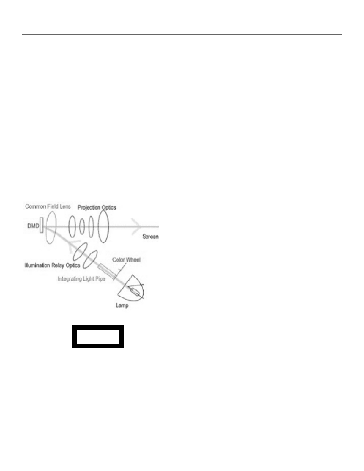
How DLP Works
In general, DLP combines microscopic mirrors, a specially
designed semiconductor, and a color wheel to adjust light to
display the most brilliant, accurate images! Your DLP HDTV
doesn’t use Cathode Ray Tubes (CRTs), which means you
don’t have to worry about screen burn (fixed video images
burning onto the screen permanently) or convergence
(realigning the CRTs). The diagram on the left illustrates the
complex system.
Thin and Light
The efficiency of DLP technology enabled our design team
to create a high-performance HDTV that is about 16 inches
thin and weighs less than 100 pounds.
Service Model Number Numéro de Modéle-Service
HDLP50XXXXXX
000000000 X
SERIAL SERIE LAMP
EXAMPLE: Service Model Number sticker
with lamp type listed.
Model No.____________________________________
Lamp Type___________________________________
Date_________________________________________
Digital Light Processing, DLP and DLP Cinema are trademarks of Texas Instruments. All other products and names may or may not be
trademarks or registered trademarks of their respective companies.
Lamp Replacement
DLP technology uses a special lamp. Eventually, you’ll need
to replace this lamp, which you can do yourself by
following the replacement instructions on page 74. To order
the correct lamp, you’ll need to know your TV’s model
number, serial number, and lamp type—this information is
listed on the Service Model Number sticker (example of the
sticker is shown on the left). The sticker is located on the
right side of the TV. The lamp type can also be found in the
TV’s Lamp Power menu. Go to page 67 for more
information. For future reference, write down the
information in the space provided at the left.
1
Introduction
Part 2: Why RCA Scenium DLP is better
DLP is just part of the story. You have chosen to embark on the next generation of TV viewing— HDTV. There are many
technological advancements that make HDTV better than analog TV, but there are basically three things about HDTV that
bring you a superior viewing experience: (1) resolution, (2) aspect ratio, and (3) digital signal and sound.
Resolution (it’s math...that works for you)
The crisp, lifelike picture that people rave about when experiencing true HDTV is due to the resolution this technology
provides. The resolution is measured by calculating the number of active lines of pixels. A pixel (which stands for picture
element) is a small dot. The picture you see on your TV is composed of these dots.
A regular, analog television only has a resolution of about 200,000 pixels (480 vertical pixels x 440 horizontal pixels =
211,200 pixels). The HDTV format is capable of more than 2 million pixels (1,920 x 1,080 = 2,073,600).
More pixels equal more detail. In summary, HDTV is capable of resolution that is up to 10 times the resolution of the
picture on a regular, analog TV!
Feature Analog (NTSC) HD Digital (ATSC)
Total Scan Lines 525 1125
Effective Scan Lines 480 1080
Aspect Ratio 4:3 16:9 (Widescreen)
Max Resolution 720 x 480 1920 x 1080
Sound 2-ch Stereo 5.1 ch Surround
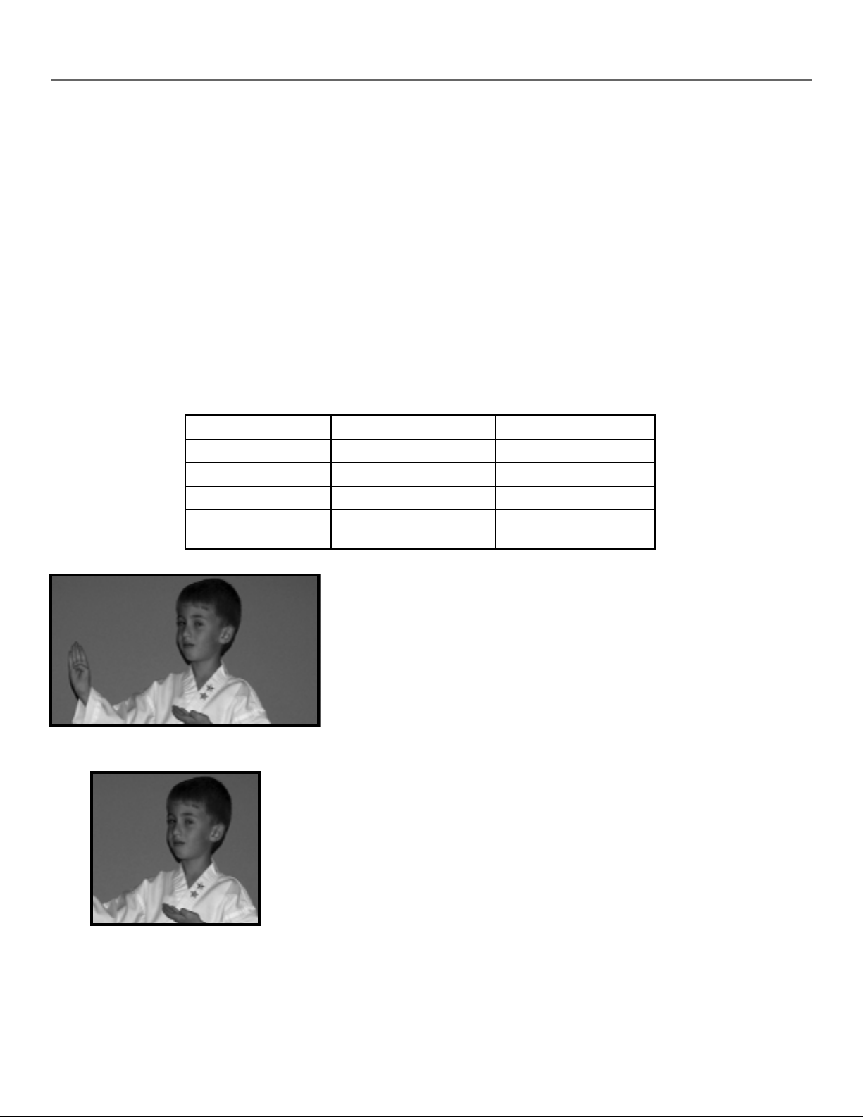
16:9 Aspect Ratio
4:3 Aspect Ratio
Aspect Ratio
Aspect ratio is simply the width and height of the picture. Regular TVs use a
4:3 aspect ratio, which means the picture is a little wider than it is tall (a
screen that is 20 inches wide is about 15 inches tall).
When the standards were being developed for television broadcasting in
1941 by the NTSC (the National Television Standards Committee), it made
sense to adopt the 4:3 aspect ratio the film industry was using at that time.
As TVs dropped in price and people prospered in the 1950s, the movie
industry had to find a way to get people out of their living rooms and back
to the movie theatres. That’s when they created the 16:9 aspect ratio (also
called widescreen format). When the standards for HDTV were being
developed by the ATSC (Advanced Television Standards Committee), the 16:9
aspect ratio was chosen as the format for HDTV.
This widescreen format makes sense because it’s much closer to the way we
see. Our field of vision is actually much wider than tall because of our
peripheral vision. Not only is it closer to the way we see, but the pictures are
crisper and cleaner with more detail in the close-up and panoramic views.
2

Introduction
Digital Signal and Sound
The analog television broadcast system that has been used in the United States for the past 50 years transmits signals as
electronic waves. These waves can suffer degradation as the signal travels to your home. Additionally, the analog waves are
susceptible to interference from planes passing overhead, weather, and household appliances.
Digital signals, in contrast to analog signals, can be reproduced precisely because the images are transmitted and received
using the computer language of 1s and 0s. Such precision yields a signal that is capable of displaying studio-quality picture
and Dolby Digital 5.1 channel sound.
Part 3: Other Key Features of owning an RCA Scenium HDTV
There are other HDTV’s on the market- even some that use DLP technology. But your RCA Scenium HDTV has been
designed with features that will enhance your TV viewing experience, and features that provide flexibility to build on the
digital revolution that is taking place. A summary of your TV’s most unique features follows. Go to Chapter 3 for more
details on these and additional features.
Integrated HDTV Tuner with Digital Cable Ready QAM
RCA was the first to offer an integrated tuner with its HDTVs (which means there is no need for another box to receive
digital programming). Now, we’ve gone one better— your HDTV’s tuner is digital cable ready (no need for a cable box to
view unscrambled digital cable programming). The CableCARD™ slot on your HDTV allows you to use a digital cable card
to access digital cable. The tuner is able to decode all 35 formats of digital television broadcasts, and it can interpret
unscrambled digital cable signals because it includes QAM (Quadrature Amplitude Modulation).
Note: A digital cable card may be necessary to view scrambled (encrypted) channels. Contact your cable provider for
more information. Go to page 17 for more information.
TruScan Digital Reality
The intelligent signal processing of TruScan Digital Reality recognizes incoming video signals and progressively converts
them to achieve optimum digital picture performance. It also recognizes when original film sources have been modified and
can automatically convert the analog frame rate back to its original format to bring out the detail--a process commonly
referred to as reverse 3:2 pulldown.
User-friendly Features Help You Personalize Your TV
• You can customize your TV to fit your viewing taste and match the lighting
where you watch TV by using Personal Presets and/or the automatic picture
quality settings: Vibrant (Day), Natural, Cinematic (Night), Videogame,
Professional. You can adjust each input jack to a different setting and the TV
will automatically adjust the picture when you change inputs.
• Help Text: The elaborate, on-screen help text describes your TV’s features
and explains how to use them.
Go Back
0
Picture Settings
1
Picture PresetsPicture Presets
2
Auto Color
3
Color Warmth
4
Noise Reduction
5
Green Stretch
6
Edge Enhancement
7
Contrast Expand
8
Advanced Settings
9
Main Menu Picture Quality
Vibrant (Day)
Natural
Cinematic (Night)
Videogame
Professional
Personal
A change in this screen is applied to Input 3.
Press or to point to an option, then press OK to select it.
Press to return to the menu.
Contrast
Color
Tint
Black Level
Sharpness
Auto Color
Color Warmth
Noise Reduction
Green Stretch
Edge Enhancement
Contrast Expand
Frame Comb
Help text
65%
70%
55%
60%
55%
On
Cool
High
Low
High
CableCARD is a registered trademark of Cable Television Laboratories, Inc.
3

Introduction
FireWire® with Two-W ay DTVLink®
Control your DTVLink components via your HDTV! Just link them together via the 2-way DTVLink
jacks and you can network your compatible DTVLink digital components. The two-way jacks allow
the audio and video signals to flow into and out from DTVLink components, such as the DVR2080 or
DVR2160 (see below).
Compatible with the Optional Audio Video Hard Disk Drive — Pause Live
Digital TV and Record Digital Programs
RCA offers an Audio Video Hard Disk Drive (model DVR2080 or DVR2160) with DTVLink, available at
your local RCA dealer or www.rca.com. The DVR2080 or DVR2160 Audio Video Hard Disk Drive
(ADVHDD) component lets you pause live TV, record shows, and play them back (it records digital
broadcasts only--ATSC and QAM signals).
NetConnect
With an Ethernet connection and a web browser built into your TV, you can
access the Internet from your TV*. To use the web browser, you’ll need a highspeed connection, such as a DSL (Digital Subscriber Line) unit or cable modem
and a subscription to an ISP (Internet Service Provider). DSL, cable modem, and
ISP subscription sold separately.
To get the most out of your HDTV’s web
browser, purchase the keyboard (model
KBR755TA1) designed specifically for your TV
(go to page 84 for ordering information).
Additionally, your RCA Scenium HDTV enables you to access photos directly
from your PC and display them on the TV! To find out more about this feature,
go to www.rca.com/Access/Scenium/311.
*The browser can’t interpret all types of files, such as streaming audio and video.
Audio System
Enjoy the great sound system in your HDTV with 40 watts total power. Your HDTV has front
speakers with two 1” tweeters and two 5” midrange drivers. A 7-band on-screen graphic equalizer
allows customization of the sound quality. TruSurround XT™ solves the problem of playing 6.1
multichannel content over two speakers. It delivers compelling, virtual surround sound experience
through the internal television speakers.
You can take advantage of the 6-Channel direct Audio Outputs (Matrix Surround, Subwoofer, etc.)
if you have an amplifier you want to connect to your HDTV. Then choose to control the volume
from the TV or the amplifier in the Fixed/Variable Output option in the Audio Connections menu.
If you own an amplifier with digital audio, connect to the DIGITAL AUDIO OUTPUT jack instead.
Audio/Video Output Jacks
Because the VCRs in most households are analog and can’t receive or record digital TV signals,
recording digital TV broadcasts wasn’t possible without purchasing additional equipment. That’s
why RCA added AUDIO/VIDEO OUTPUT jacks to this HDTV. These jacks enable you to record
both analog and digital programs. RCA understands how you watch TV and what’s necessary to
make the transition to HDTV seamless.
TruSurround XT, SRS and the symbol are trademarks or registered trademarks of SRS Labs, Inc.
DTVLink® Certification Logo is a U.S. registered mark of CEA.
FireWire® is a trademark of Apple Computer, Inc., registered in the U.S. and other countries.
4

Table of Contents
Introduction .............................................................................................. 1
Chapter 1: Connections & Setup
Things to Consider Before You Connect ........................................................................................ 8
Protect Against Power Surges.................................................................................................. 8
Protect Components from Overheating.................................................................................. 8
Position Cables Properly to Avoid Audio Interference........................................................... 8
Use Indirect Light...................................................................................................................... 8
Using a Stand ............................................................................................................................ 8
Cables You May Need to Connect Components to Your TV .................................................. 8
Choose Your Connection ................................................................................................................. 9
Explanation of Jacks and Cables .................................................................................................. 10
The Front of Your TV ..................................................................................................................... 14
Front Input Jacks..................................................................................................................... 14
Front Panel.............................................................................................................................. 14
How to Connect: TV + VCR + DVD Player ............................................................................. 15
How to Connect: TV + Satellite Receiver + VCR.................................................................... 16
How to Connect: TV + DTVLink Components ....................................................................... 17
How to Connect: TV + Component with DVI or HDMI......................................................... 18
How to Connect: TV + CableCARD ........................................................................................ 19
Setting Up Digital Cable Television Service........................................................................... 19
Audio Connections ................................................................................................................. 20
How to Connect: TV + Router via the HDTV’s ETHERNET Jack ............................................ 22
Plug in the TV................................................................................................................................. 23
Put Batteries in the Remote.......................................................................................................... 23
Turn on the TV ............................................................................................................................... 23
Use the Remote Control to Complete the Assisted Setup.......................................................... 23
Complete the Assisted Setup........................................................................................................ 24
Set the Menu Language......................................................................................................... 24
Complete Channel Search...................................................................................................... 24
Chapter 2: Using the Remote Control
The Buttons on the Remote Control ............................................................................................ 26
Programming the Remote to Operate Other Components ........................................................ 28
Find Out If You Need to Program the Remote ..................................................................... 28
Programming the Remote ..................................................................................................... 28
How to Use the Remote After You’ve Programmed It ............................................................... 29
The Learning Feature .................................................................................................................... 30
Adding a Learned Function ................................................................................................... 30
Clearing a Learned Function.................................................................................................. 31
Deleting ALL Learned Functions............................................................................................ 31
Volume Punchthrough Feature.....................................................................................................32
Deleting ALL Volume Punchthrough Commands................................................................. 32
Using the INPUT Button ................................................................................................................ 33
Remote Code List........................................................................................................................... 33
Chapter 3: Using the TV’s Features
About the Channel Banner ........................................................................................................... 36
Digital or Analog TV Channels ..................................................................................................... 37
Direct Tuning to a Channel .................................................................................................... 37
Parental Controls ........................................................................................................................... 38
Lock/Unlock TV ....................................................................................................................... 38
Channel Lists (Video Input List, Cable Channel List, Antenna Ch. List)............................... 38
How V-Chip Works for the USA and Canada............................................................................... 39
USA V-Chip TV Ratings ...........................................................................................................39
Canada V-Chip ........................................................................................................................ 43
Auto Tuning Feature...................................................................................................................... 45
PIP (Picture-in-Picture) Operation................................................................................................. 46
5

Table of Contents
Using the Web Browser ................................................................................................................ 48
DTVLink Recording ........................................................................................................................ 49
Set up DTVLink Recording Preferences ................................................................................. 50
Emergency Alert System (EAS) ..................................................................................................... 50
Chapter 4: Using the TV’s Menu System
Menus, On-screen Help, and Control Panels ............................................................................... 52
Navigating the Menu System................................................................................................. 52
On-Screen Help ....................................................................................................................... 52
Controls ................................................................................................................................... 52
Picture Quality Menu .................................................................................................................... 54
Picture Settings ....................................................................................................................... 54
Picture Presets......................................................................................................................... 54
Auto Color............................................................................................................................... 55
Color Warmth ......................................................................................................................... 55
Noise Reduction...................................................................................................................... 55
Green Stretch .......................................................................................................................... 55
Edge Enhancement................................................................................................................. 55
Contrast Expand ..................................................................................................................... 56
Advanced Settings .................................................................................................................. 56
Audio Menu ................................................................................................................................... 57
Equalizer Presets..................................................................................................................... 57
Audio Processor ...................................................................................................................... 57
Sound Logic............................................................................................................................. 58
Audio Mode ............................................................................................................................ 58
SAP (Second Audio Program)................................................................................................. 58
Balance .................................................................................................................................... 58
Audio Connections ................................................................................................................. 59
Recordings Menu........................................................................................................................... 60
Connections Menu......................................................................................................................... 60
Signal Strength ....................................................................................................................... 60
Channel Search ....................................................................................................................... 61
Software Upgrade .................................................................................................................. 61
Signal Source........................................................................................................................... 61
Video Input Setup................................................................................................................... 61
Auto Tuning............................................................................................................................ 62
DTVLink Setup ........................................................................................................................ 62
Special Features ...................................................................................................................... 62
Ethernet Setup........................................................................................................................ 63
Preferences Menu.......................................................................................................................... 64
Closed Captioning .................................................................................................................. 64
Screen Format ......................................................................................................................... 66
Time Menu .............................................................................................................................. 66
Color Scheme .......................................................................................................................... 67
Translucency............................................................................................................................ 67
Menu Language...................................................................................................................... 67
Power Indicator ...................................................................................................................... 67
Lamp Power ............................................................................................................................ 67
Chapter 5: Reference
Troubleshooting............................................................................................................................. 70
Lamp Replacement Instructions ...................................................................................................74
HDTV Specifications ...................................................................................................................... 77
Accessory Information .................................................................................................................. 79
Custom DLP HDTV Accessories............................................................................................... 79
Limited Warranty........................................................................................................................... 81
Care and Cleaning ......................................................................................................................... 82
FCC Information............................................................................................................................. 82
6

Chapter 1
Connections & Setup
Chapter Overview:
• Things to Consider Before You Connect
• Choose Your Connection
• Explanation of Jacks and Cables
• The Front of Your TV
• How To Connect
• Plug in the TV
• Put Batteries in the Remote
• Turn on the TV
• Use the Remote Control to Complete
the Assisted Setup
• Complete the Assisted Setup
Graphics contained within this publication are for representation only. 7
Connections & Setup
Things to Consider Before You Connect
Protect Against Power Surges
• Connect all components before you plug any of their power cords into the wall outlet or
power strip. NEVER plug your TV into an outlet that is controlled by a wall switch.
• Turn off the TV and/or component(s) before you connect or disconnect any cables.
• Make sure all antennas and cables are properly grounded. Refer to the Important Safety
Instructions packed with your TV.
Protect Components from Overheating
• Don’t block ventilation holes on any of the components. Arrange the components so that air
can circulate freely.
• Don’t stack components.
• If you place components in a stand, make sure you allow adequate ventilation.
• If you connect an audio receiver or amplifier, place it on the top shelf so the heated air from it
won’t flow around other components.
Position Cables Properly to Avoid Audio Interference
• Insert each cable firmly into the designated jack.
Use Indirect Light
Don’t place the TV where sunlight or room lighting will be directed toward the screen. Use soft or
indirect lighting.
Using a Stand
If a stand, base, or cabinet is used, insure that it is of adequate size and strength to prevent the TV
from being accidentally tipped over, pushed off, or pulled off. This could cause personal injury
and/or damage the TV. Refer to the Important Safety Instructions packed with your TV.
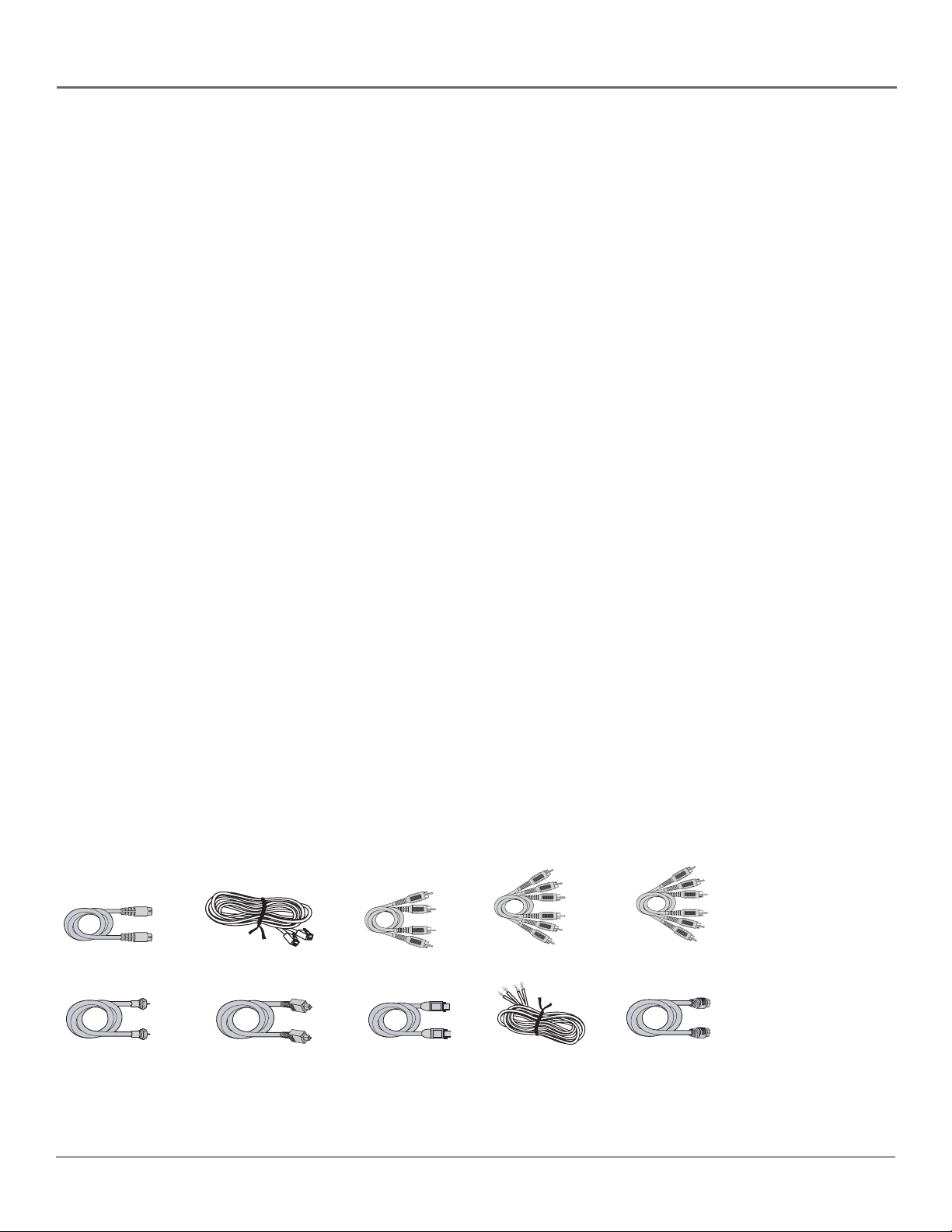
Cables You May Need to Connect Components to Your TV
The pictures below show the cables (not supplied) you may need for the connections represented
in this book.
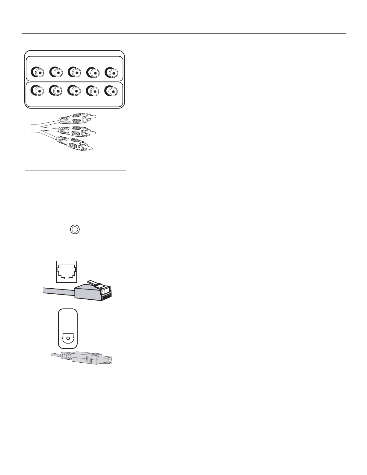
S-Video cable
CAT5 (Ethernet) Cable
Audio Cables
Composite Video
Audio/ Video cable
Component Video
(Y, Pb, Pr) cable
Coaxial cable
HDMI and High-Definition Multimedia Interface are trademarks or registered trademarks of HDMI Licensing LLC.
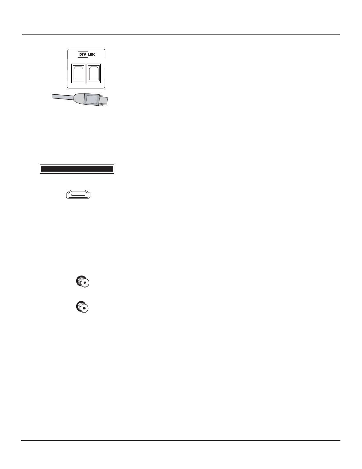
Digital Optical Cable
DTVLink Cable
Speaker Wire
HDMI™ cable (or DVI
cable and HDMI/DVI
adapter)
8 Chapter 1
Connections & Setup
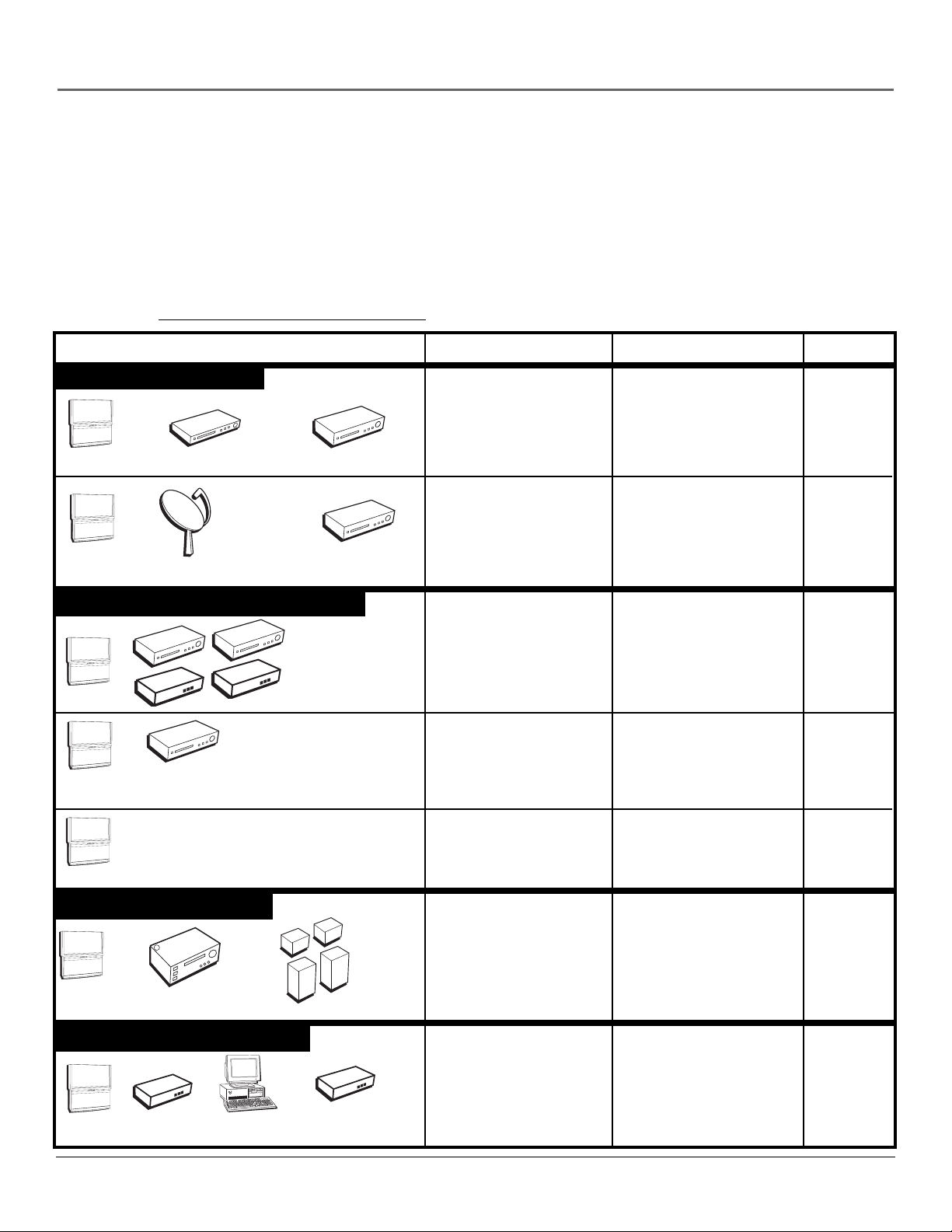
Choose Your Connection
There are several ways to connect your HDTV, depending on the components you want to connect and the quality of the
signal you want to achieve. Please use the following chart to determine which connection is best for you. Proceed to the
appropriate page and connect your TV. For more information about the relationship between the cables, jacks, and the
quality of the signal you see on your TV, go to following page.
Note for U.S. Customers: If you prefer, we can provide you with the name of an Authorized Service Representative
who will visit your home for a fee to install your electronic entertainment system and to instruct you in its operation.
For details about this service, call 1-888-206-3359. For additional assistance while using your RCA Scenium product,
please visit www.rcascenium.com/customer support.
Components Cables Needed Connection Title Go to...
Video Connections
R
OWE
P
+
L
O
V
—
OL
V
CH
CH
NU
E
M
V
T
POWER
+
VOL
—
VOL
H
C
H
C
MENU
V
T
DVD
V
V
Satellite Receiver
Digital/Network Connections
R
E
POW
+
OL
V
—
L
O
V
CH
CH
U
MEN
m
o
C
k
in
V
T
OWER
P
+
L
VO
—
VOL
CH
CH
MENU
ponent w
V
T
Com
I or DVI jack
HDM
L
V
T
D
ith
Coaxial
Audio
Component
R
C
Composite
Coaxial
Audio
R
C
Composite
TV + VCR + DVD
Player
TV + Satellite
Receiver + VCR
page 15
page 16
S-Video
Coaxial
ts
n
e
n
o
p
DTVLink
Coaxial
HDMI (or DVI with
TV+ DTVLink
Components
TV + Component
with DVI or HDMI
page 17
page 18
HDMI/DVI adapter)
POWER
+
VOL
—
OL
V
H
C
CH
ENU
M
RD
™
Coaxial TV + CableCARD™
page 19
CableCA
V
T
Audio Connections
OWER
P
+
VOL
—
VOL
CH
H
C
NU
E
M
TV
A/V Receiver
Speakers
Coaxial
Optical cable or Audio
cables
Speaker wire
TV + A/V Receiver +
Speakers
or
TV + Receiver w/
Dolby Digital +
Speakers
pages 20,
21
Advanced Connections
Coaxial
ER
POW
+
VOL
—
VOL
H
C
CH
MENU
CAT5
(Ethernet)
Cable
Modem
TV
Router
Computer
Chapter 1 9
TV + Router via the
HDTV’s ETHERNET
jack
page 22
Connections & Setup
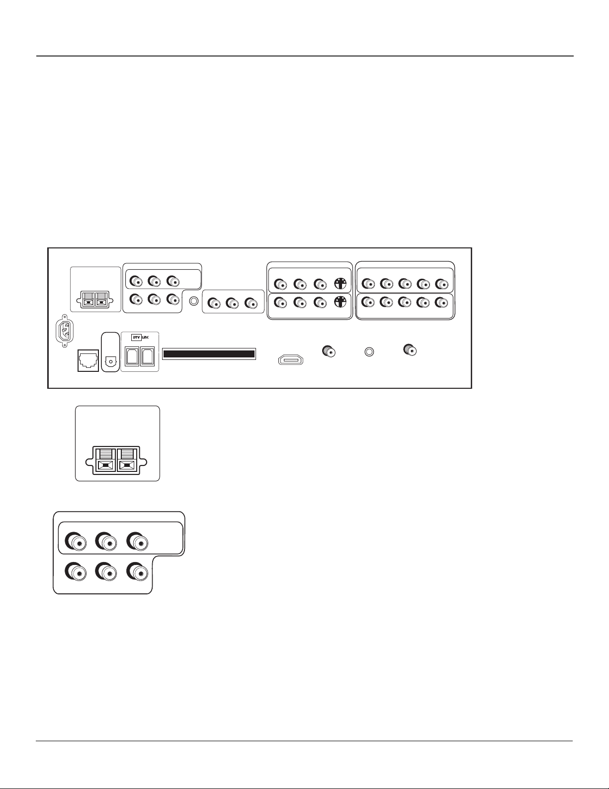
Explanation of Jacks and Cables
The diagrams below illustrate jacks found on the back of the TV. When connecting cables, be sure
to connect corresponding outputs and inputs (video input into video out, right audio input into
right audio out, etc.).
This section describes the jacks and cables you might use to make connections (cables may be
ordered separately by calling the number on page 79). There are several ways to connect
components to your TV.
Different jacks and cables provide a different level of performance. It’s important to remember the
different degrees of picture quality for comparison. The HDMI/DVI, DTVLink, and component
jacks are considered excellent; S-Video is very good; composite jacks are good, while connecting
components to the Antenna or Cable input is fair.
TV
CENTER SPEAKER INPUT
EXTERNAL AMP
MAX POWER RATING!
(60 WATTS into 8 OHMS)
POWER
(AC 120V~60Hz)
DIGITAL
AUDIO
ETHERNET
OUTPUT
CENTER SPEAKER INPUT
EXTERNAL AMP
MAX POWER RATING!
(60 WATTS into 8 OHMS)
FIXED/VARIABLE AUDIO OUTPUTS
CENTER
R REAR
FIXED/VARIABLE AUDIO OUTPUTS
R REAR
CENTER
SUBWOOFER
L REAR
L REAR
R
L
MATRIX
SURROUND
OUTPUTS
MATRIX
SURROUND
OUTPUTS
WIRED
IR
CableCARD™
COMPONENT/COMPOSITE INPUTS
Use menu for composite video.
L
R
L
R
For Factory Use Only
INPUT 4
R
P
P
B
P
R
P
B
INPUT 2
ANTENNA INPUT
Y/VIDEO
Y/VIDEO
R
AUDIO/VIDEO
OUTPUT
L
V
COMPOSITE INPUTS
INPUT 3
R
L
R
L
INPUT 1
HDMI/DVI INPUT
Use menu for DVI audio.
V
V
CABLE
INPUT
S-VIDEO
S-VIDEO
SPEAKERS
• CENTER SPEAKER INPUT To use the TV’s internal speakers as the center
speaker, connect the audio/video receiver’s center channel output to the
TV’s center channel input.
Note: Go to Center Speaker In in the Audio Connections menu to choose
the option The center channel output from an audio receiver.
AUDIO/VIDEO OUTPUTS
FIXED/VARIABLE AUDIO OUTPUTS
• CENTER Provides center surround sound to an A/V receiver or audio
amplifier.
SUBWOOFER
R
L
Note: To turn the TV’s internal speakers on and off, press MENU on the
remote control and choose Audio, then Audio Connections. Then choose
Fixed/Variable Out from the menu and choose an option.
• SUBWOOFER Provides lower bass frequencies out from the TV and to a
subwoofer or audio receiver with a subwoofer jack.
Note: Go to Fixed/Variable Output in the Audio Connections menu to set
option to Yes if an external subwoofer is being used.
• R and L Provides right front and right rear mixed sound, and left front and
left rear mixed sound.
10 Chapter 1
• R and L REAR Provides right and left rear surround sound.
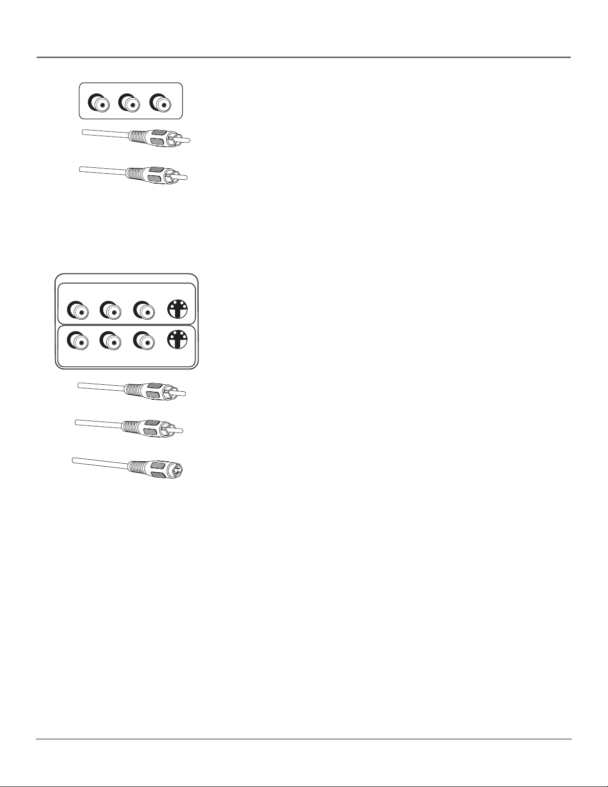
Connections & Setup
AUDIO/VIDEO
OUTPUT
R
Composite Audio Cable (RCA Type)
Composite Video Cable (RCA Type)
COMPOSITE INPUTS
R
R
INPUT 3
L
L
INPUT 1
L
V
AUDIO/VIDEO OUTPUT Connect a VCR or DVD-recorder to record digital
and analog programs from the Cable or Antenna Input (excluding copy-
V
protected programs and component video formats) while the TV is turned on.
You must leave the TV on the same channel you are recording.
• R Audio provides right audio connection and connector is usually red.
• L Audio provides left audio connection and connector is usually white.
• V (Video) provides composite video connection and connector is usually
yellow.
Notes: When recording from this output, remember to tune to the
channel you want to record.
If an unusual pattern appears when you connect a VCR to these jacks,
playing a tape or switching to the VCR’s tuner removes the pattern.
AUDIO/VIDEO INPUTS
S-VIDEO
S-VIDEO
V
INPUT 1 COMPOSITE INPUT Connect an NTSC (analog) component. These
jacks are used for most audio/video connections between components. The
audio/video jacks are often color coded (yellow for video, red for right audio,
and white for left audio).
• R Audio provides right audio connection and connector is usually red.
• L Audio provides left audio connection and connector is usually white.
Composite Audio Cable (RCA Type)
Composite Video Cable (RCA Type)
S-Video Cable
• V (Video) provides composite video connection and connector is usually
yellow.
• S-VIDEO lets you connect an S-Video cable for better picture quality to a
component with S-Video capability, such as a VCR or DVD player. When
using S-Video, make sure to connect the two audio cables as well as the
S-Video connector.
The S-Video jack provides better picture quality than the composite video
jacks because the color (chrominance, also called chroma) part of the
signal is separated from the black and white (luminance) part of the
picture.
INPUT 3 COMPOSITE INPUT Provides connection to a second NTSC (analog)
video component such as a VCR. The jacks are the same as described above for
INPUT 1.
Chapter 1 11
Connections & Setup
COMPONENT/COMPOSITE INPUTS
Use menu for composite video.
INPUT 4
R
Component Cables
L
L
ETHERNET
P
R
R
P
INPUT 2
WIRED
IR
P
P
B
B
Y/VIDEO
Y/VIDEO
Y (green)
PR (red)
(blue)
P
B
R
Tip
Inputs 2/4 can be used as either a component
video (Y PB PR ) input or a composite video
(Y/Video) input. Go to the Connections menu,
choose Video Input Setup and select which
video input source you are using.
INPUT 2 COMPONENT/COMPOSITE INPUT Provides connection to a second
NTSC (analog) video component with either composite or component outputs
such as a VCR.
• R Audio provides right audio connection and connector is usually red.
• L Audio provides left audio connection and connector is usually white.
• Y/Video PB PRUnlike a single video input, component (Y PB PR) video
maintains the video signal as three separate parts through these three jacks.
To ensure maximum picture quality, use three video-grade cables for the
Y PB PR connections. Accepts 480i, 480p, 720p, and 1080i signals. If you’re
connecting to a component with a Video jack instead, you can still use the
Y/Video jack. Go to the Connections menu, select Video Input Setup and
choose Composite video as your source. Go to page 61 for more
information.
Notes: Also, remember to connect the left and right audio cables
because the Y, Pb, Pr cables carry only the picture signal, not the sound.
PIP can only be displayed from component inputs in 480i format.
INPUT 4/ COMPONENT/COMPOSITE INPUT Provides connection to a
second optional component video source, such as a DVD player or satellite
receiver. The jacks are the same as described above for INPUT 2.
WIRED IR This jack is for connecting a wired remote control system, which
is primarily for professional installers. If you’re using the remote that was
included with your TV, don’t plug anything into this jack or the TV won’t
respond to the remote.
ETHERNET Connect a router, cable modem, or Digital Subscriber Line (DSL)
modem to the TV using an Ethernet cable (CAT 5). Do not connect a telephone
cable because of risk of fire or shock. A green light on the jack means that an
active network has been detected. An orange light on the jack means the data is
either being sent or received.
DIGITAL
AUDIO
OUTPUT
DIGITAL AUDIO OUTPUT Use a digital optical cable (or SPDIF cable) to
connect your TV to a compatible Dolby Digital* and/or PCM receiver and/or
decoder. Dolby Digital offers theatre-quality sound (six audio channels). If you
own a receiver that uses an optical cable input, you can use an optical cable to
connect the TV to that receiver for the best sound quality. Go to the Digital
Audio Out screen in the Audio menu to select Auto Select or PCM as the output
for this jack.
Note: This TV’s optical digital output jack fully complies with the
international standard governing this type of jack (IEC958), and is
designed for connection to a Dolby Digital (AC-3® or PCM) receiver or
decoder. Older equipment, some of which is not fully compliant with
IEC958, may not be compatible with the Dolby Digital bitstream. Such a
connection using anything other than a Dolby Digital (AC-3 or PCM)
receiver or decoder could create a high noise level, causing damage to
headphones or speakers.
*Manufactured under license from Dolby Laboratories. “Dolby” and the double-D symbol are trademarks of Dolby
Laboratories.
12 Chapter 1
CableCARD™
HDMI/DVI INPUT
Use menu for DVI audio.
Connections & Setup
DTVLink DTVLink uses a connection and jack better known to some as
IEEE-1394 or FireWire®. It is a compressed digital video input/output offering
an IEEE 1394-type connection that meets the CEA specifications. This
connection is a high-speed way of interconnecting 1394 compliant consumer
electronic components. If your 1394 component has the DTVLink logo on it, it
should work with this TV. Use either or both connectors to connect compatible
DTVLink components but don’t loop the components together. When
connecting several components, use a hub or component-to-component
method. Be sure to connect the fastest of the DTVLink components closer to
the connection point of the TV and the slower components furthest away.
Details on page 17.
Notes: Audio and video information is carried on a single wire.
The TV outputs audio/video through the DTVLink jack only to a
component that enforces video copy protection.
CableCARD
cable services, including premium and HDTV cable channels, without the need
for a set-top box. Go to page 19 for information on using the CableCARD slot.
HDMI/DVI INPUT (High-Definition Multimedia Interface/Digital Visual
Interface) Provides an uncompressed digital interface that carries both video
and audio data by way of an integrated mini-plug cable. Since HDMI is based
on Digital Visual Interface (DVI) the jack on the back of your TV is compatible
with DVI components.
Allows you to use a digital cable television card to receive digital
CABLE
INPUT
ANTENNA INPUT
Note: If you connect a component with a DVI jack to the HDMI/DVI
input, you’ll need an HDMI to DVI adapter. Also, connect the left and
right audio cables to an input that is not in use. An example is shown
on page 18. Then go to the Audio Connections menu and select DVI
Audio Input to choose the input you’re using to receive audio.
CABLE INPUT Used to connect a coaxial cable to receive the signal from
cable or cable box.
ANTENNA INPUT Used to connect a coaxial cable to receive the signal from
an off-air antenna.
Chapter 1 13
Connections & Setup
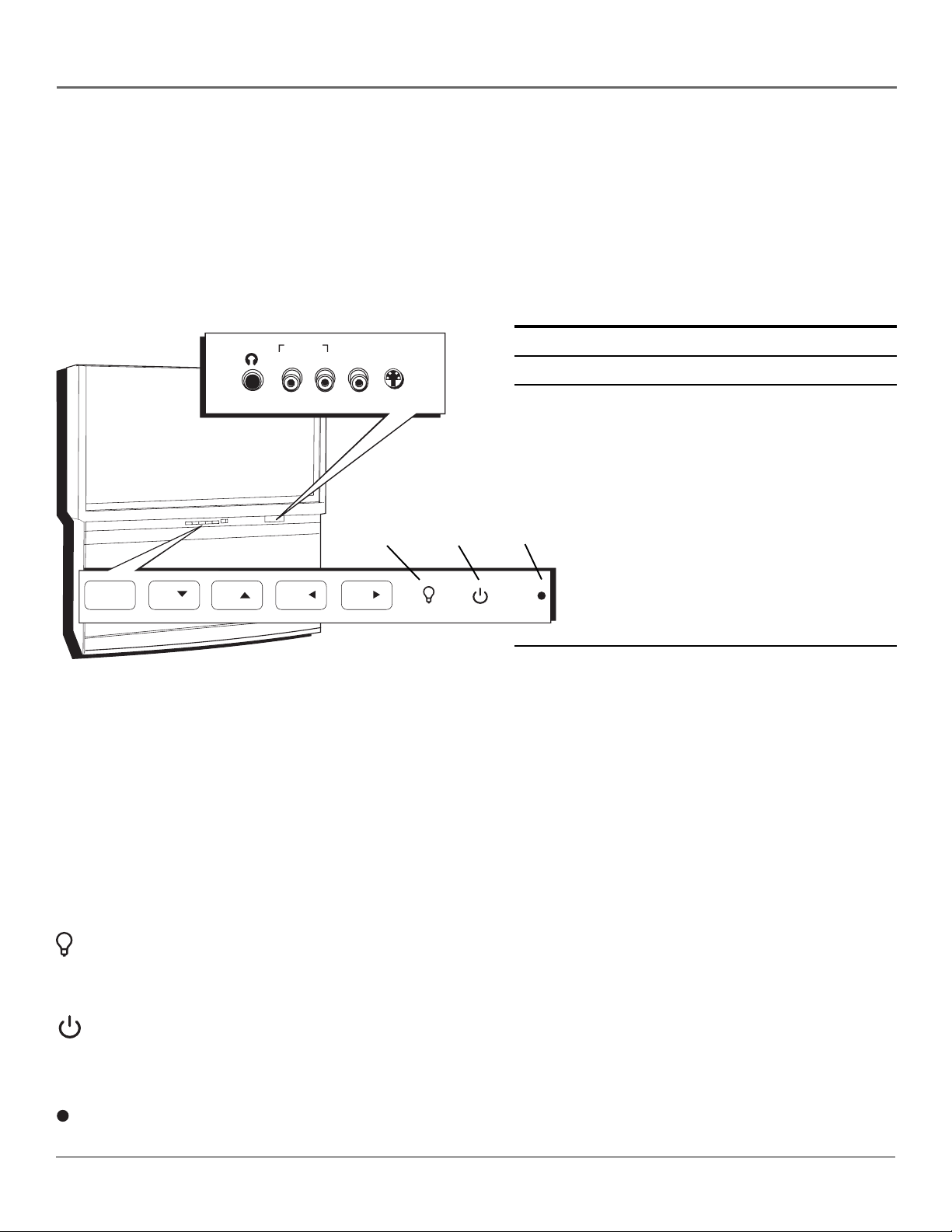
The Front of Your TV
Front Input Jacks
The TV has front input jacks for convenience in connecting a camcorder, digital camera, or video game. Look for a hinged
door and press to open the cover. Please note the illustration below is just an example of how jacks might appear.
Notes: When you plug in headphones, the TV’s internal speakers are muted. Use the VOL up or down button to
control the volume.
When connecting a component that uses a monaural cable, such as some camcorders, use the L/MONO input jack to
get sound from both speakers.
Power Indicator Light Status
AUDIO IN VIDEO S-VIDEO
L/MONO R IN IN
On TV is on
Off TV is off (standby mode)
HEADPHONE
Blinks Light blinks 5 times, pauses, and blinks again 5 times:
Lamp is trying to turn on. If the TV doesn’t turn on after
5 minutes and then the light blinks steadily for one
minute, one of the following options is possible:
R
E
W
O
P
+
L
O
V
—
L
O
V
H
C
H
C
U
N
E
M
Backlight
Power
button
Power
indicator
Lamp door is open. Locate the door on the side of the
TV and close it. Turn off the TV and turn back on. The
lamp should turn on.
Lamp is dead. You can replace the lamp yourself
following the instructions on page 74. Go to page 79
MENU/OK
MENU/OK
CHCH
CHCH
VOLVOL
VOLVOL
for ordering information.
Lamp power supply within TV may need service. Go to
page 81 for warranty information.
Notes: The front panel illustration shows a typical front panel layout. The exact look may
be different from the one on the front of your TV.
If you use the Front Button Block feature, the front panel no longer provides access to the
menus. The Front Button Block feature disables all front panel buttons but not the jacks.
Front Panel
For more information, see Chapter 3.
If you cannot locate your remote, you can use the front panel of your TV to operate many of the TV’s features.
MENU/OK Brings up the Main menu. When the menu system is displayed, pressing MENU/OK selects highlighted items.
CH
Scans down through the channel list. In the menu system, it moves the highlight down and adjusts menu controls.
CH
Scans up through the current channel list. In the menu system, it moves the highlight up and adjusts menu controls.
VOL
Decreases the volume. In the menu system, it moves the highlight left to items and adjusts menu controls.
VOL
Increases the volume. In the menu system, it moves the highlight right to items and adjusts menu controls.
(Backlight) Press to activate backlighting for MENU/OK, CH, and VOL buttons. A few seconds after the last button
press, the backlight turns off.
Note: Pressing any front panel button also activates the backlight.
(Power button) Turns the TV on and off. The indicator lights when TV is on. Your HDTV’s lamp has a cooldown
period when the TV is turned off, and a warm up period when the TV is turned on. If you try to turn the TV on during a
cooldown, you will hear audio and then the picture will be displayed after a few moments. This could take up to one
minute.
(Power indicator) See above for different light status of the indicator. The brightness of the light can be controlled in
the Preferences menu. Go to page 67 for more information.
14 Chapter 1
Connections & Setup
R
P
P
R
INPUT 2
DVD
L/
L/
2B
L/
P
B
Y/VIDEO
P
B
Y/VIDEO
OFF-AIR ANTENNA
CABLE
1
ER
POW
+
VOL
—
HVOL
C
CH
ENU
M
TV
DVD
VCR
TV
CENTER SPEAKER INPUT
(60 WATTS into 8 OHMS)
POWER
(AC 120V~60Hz)
ETHERNET
EXTERNAL AMP
MAX POWER RATING!
DIGITAL
AUDIO
OUTPUT
VCR
ANTENNA OUT
FIXED/VARIABLE AUDIO OUTPUTS
R REAR
CENTER
SUBWOOFER
ANTENNA IN
IN
IN
R
OUT
VIDEOL
PR PB Y S-VIDEO
L/
VIDEOL
AUDIO
R
2A
COMPOSITE INPUTS
L REAR
MATRIX
SURROUND
OUTPUTS
R
L
WIRED
IR
CableCARD™
R
AUDIO/VIDEO
OUTPUT
L
V
3B
VIDEOAUDIO
LR
OUT
R
L
R
HDMI/DVI INPUT
Use menu for DVI audio.
3A
VIDEOAUDIOLR
INPUT 3
L
INPUT 1
V
V
CABLE
INPUT
S-VIDEO
S-VIDEO
For Factory Use Only
COMPONENT/COMPOSITE INPUTS
Use menu for composite video.
INPUT 4
L
R
L
R
ANTENNA INPUT
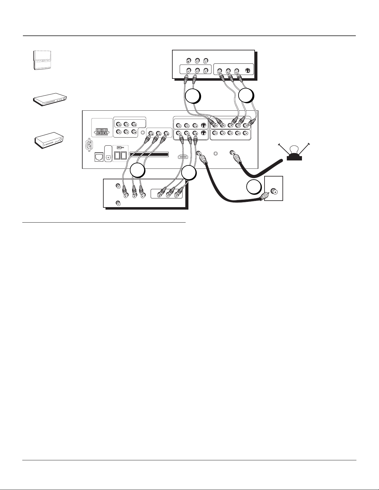
How to Connect: TV + VCR + DVD Player
1. Connect your cable and/or off-air antenna.
If you have cable and an off-air antenna, connect the cable signal to CABLE INPUT. Connect the off-air antenna to
ANTENNA INPUT.
2. Connect your DVD Player to your TV.
A. Connect the audio (white and red) cables to the INPUT 4 R and L Audio jacks on the back of the TV and to the
Audio Output jacks on the DVD player.
B. Connect three video grade cables to the INPUT 4 Y/VIDEO PB PR jacks on the back of the TV and to the Y PB P
outputs on the DVD player. If your DVD player doesn’t have Y PB P
but has composite video and an S-Video output,
R,
use the INPUT 3 S-VIDEO jack instead of the V (Video) jack for better picture quality.
Notes: If you are using an S-Video cable or component video cables, you must also connect audio cables. The S-Video
cable and component video cables only transfer video information.
If your DVD player has a component video output, we recommend you use the component video input on the TV instead of
the composite video or S-Video connection.
3. Connect your VCR to your TV.
A. Connect the VCR’s audio/video outputs to INPUT 1 (R and L-Audio, and V-Video) on the TV using composite audio/video
cables.
B. Connect the VCR’s audio/video inputs to AUDIO/VIDEO OUTPUT jacks on the TV. This enables recording of digital
and analog programs (except copy protected or component video formats).
Viewing the Components
1. Turn on the TV and the component(s) you want to view.
2. Press the TV button on the remote control.
3. Press the INPUT button on the remote control to scroll through the Video Input Channels.
• View the VCR on the INPUT 1 channel.
• View the DVD player on the INPUT 4 channel.
Note: You can set up the TV to automatically tune to the correct Video Input Channel. This is called Auto Tuning.
(See Chapter 3 for more information.)
Go to page 23
R
Chapter 1 15

Connections & Setup
POWER
+
VOL
—
CHVOL
H
C
ENU
M
VIDEO LR S-VIDEO
AUDIO
V
T
SATELLITE
RECEIVER
3
Satellite
Receiver
VCR
TV
CENTER SPEAKER INPUT
POWER
(AC 120V~60Hz)
EXTERNAL AMP
MAX POWER RATING!
(60 WATTS into 8 OHMS)
DIGITAL
AUDIO
ETHERNET
OUTPUT
VCR
ANTENNA IN
ANTENNA OUT
FIXED/VARIABLE AUDIO OUTPUTS
R REAR
L REAR
CENTER
SUBWOOFER
SURROUND
OUTPUTS
R
L
2B
LR
IN
MATRIX
WIRED
IR
CableCARD™
VIDEOAUDIO
R
OUT
AUDIO/VIDEO
OUTPUT
L
AUDIO
V
LR
O
COMPOSITE INPUTS
R
L
R
HDMI/DVI INPUT
Use menu for DVI audio.
2A
VIDEO
INPUT 3
L
INPUT 1
V
V
CABLE
INPUT
S-VIDEO
S-VIDEO
For Factory Use Only
COMPONENT/COMPOSITE INPUTS
Use menu for composite video.
INPUT 4
L
R
R
P
P
B
L
R
R
P
P
B
INPUT 2
ANTENNA INPUT
Y/VIDEO
Y/VIDEO
OFF-AIR ANTENNA
CABLE
1
How to Connect: TV + Satellite Receiver + VCR
1. Connect your cable and/or off-air antenna.
If you have cable and an off-air antenna, connect the cable signal to CABLE INPUT. Connect the off-air antenna to
ANTENNA INPUT.
2. Connect your VCR to your TV.
A. Connect the VCR’s audio/video outputs to INPUT 1 (R and L-Audio, and V-Video) on the TV using composite audio/
video cables.
B. Connect the VCR’s audio/video inputs to AUDIO/VIDEO OUTPUT jacks on the TV. This enables recording of digital
and analog programs (except copy protected or component video formats).
3. Connect your Satellite Receiver to your TV.
Connect the satellite receiver’s audio/video output jacks to the INPUT 3 R and L Audio and S-VIDEO jacks on the TV
using audio cables and an S-Video cable. If your satellite receiver doesn’t have an S-Video output, you can make the
video connection by using the V (Video) jack instead. If your satellite receiver has component outputs, then use INPUT
2 or 4.
Note: If you are using an S-Video cable or component video cables, you must also use audio cables. The S-Video
cable and component video cables only transfer video information.
Viewing the Components
1. Turn on the TV and the component(s) you want to view.
2. Press the TV button on the remote control.
3. Press the INPUT button on the remote control to scroll through the Video Input Channels.
• View the VCR on the INPUT 1 channel.
• View the satellite receiver on the INPUT 3 channel.
Note: You can set up the TV to automatically tune to the correct Video Input Channel. This is called Auto Tuning.
(See Chapter 3 for more information.)
Go to page 23
16 Chapter 1
TV
Digital VCR
Connections & Setup
Digital Video Recorder Digital VCR
TV
Fastest Slowest
Digital Video Recorder Digital VCR
Digital VCR
Other 1394 Component
Other 1394 Component
Hub Connection
Component-to-Component Connection
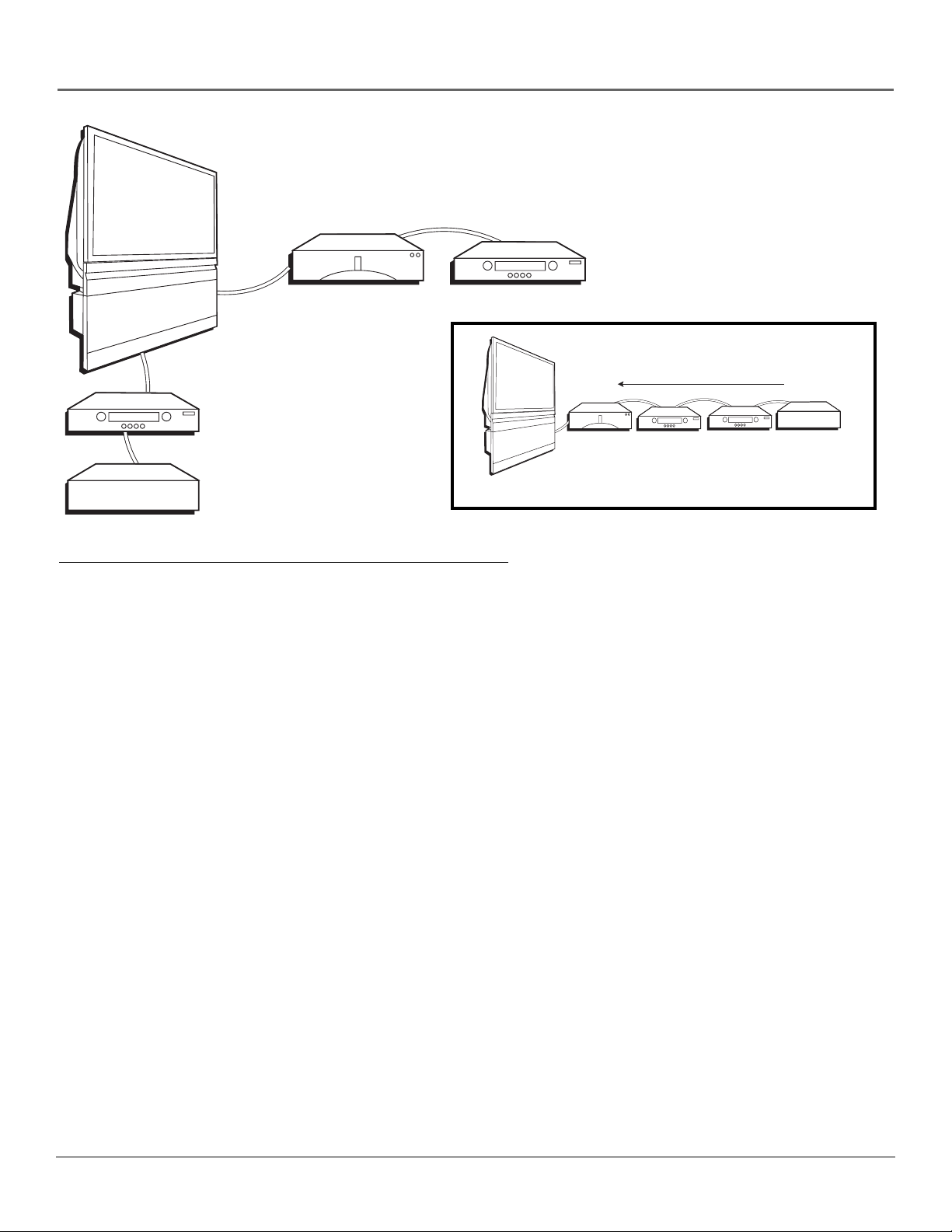
How to Connect: TV + DTVLink Components
Two connection methods when connecting DTVLink® components are: component-to-component or hub. The
component-to-component method is each component connected in a chain-like fashion, one to the other with the first
component in the chain connected to the DTVLink jack on the TV. The hub method is basically the same but using both
DTVLink jacks with two separate chains of components connected. Your TV is a control center for the connected
compatible components, automatically recognizing each component and placing it in the Input list: press the INPUT button
until you see the component name in the channel banner at the top of the screen.
Note: If you’ve tuned to a DTVLink input, you can control some basic transport functions on the component like
RECORD, STOP, FAST FORWARD, REVERSE, PAUSE, and PLAY when remote is in TV mode.
Three types of 1394 connectors are available on DTVLink components; 4-pin connector (no power); 6-pin connector (with
power) and 6-pin connector (without power supplied). Your DTVLink is a 6-pin connector (without power supplied). Both
the 4-pin and 6-pin connectors are capable of sending digital audio and video, and digital control signals back and forth
between components. If you should have some components with 4-pin connectors, 4-to-6 pin adapter cables are available
from your local electronic stores.
You should know:
• Connect your DTVLink components to either DTVLink jack.
• Only compatible DTVLink components are to be connected to the DTVLink input/output jack.
• Do not loop the DTVLink components back to the TV. That is, each component should have only one connection
point to the TV, or the network might not work.
• Place the slower components at the end of the chain and the faster ones closest to the TV in the chain for faster
communication speed. See component’s manual for 1394 network speed.
• The TV can’t decode DV format of some camcorders, but it can decode/accept MPEG2 format from some camcorders.
• Set your DTVLink component in the DTVLink Setup menu for specific recording options. Go to page 62 for more
information.
Note: The TV sends audio/video through the DTVLink jack only to a component that enforces video copy protection.
DTVLink® Certification Logo is a U.S. registered mark of CEA.
Chapter 1 17
Connections & Setup
Component with DVI
1A
TV
CENTER SPEAKER INPUT
(60 WATTS into 8 OHMS)
POWER
(AC 120V~60Hz)
ETHERNET
EXTERNAL AMP
MAX POWER RATING!
DIGITAL
AUDIO
OUTPUT
FIXED/VARIABLE AUDIO OUTPUTS
R REAR
L REAR
CENTER
SUBWOOFER
SURROUND
OUTPUTS
R
L
1B
L
R
Audio Out
MATRIX
WIRED
IR
CableCARD™
DVI Out
R
AUDIO/VIDEO
OUTPUT
L
V
COMPOSITE INPUTS
R
L
R
HDMI/DVI INPUT
Use menu for DVI audio.
OR
INPUT 3
L
INPUT 1
V
V
CABLE
INPUT
S-VIDEO
S-VIDEO
For Factory Use Only
COMPONENT/COMPOSITE INPUTS
Use menu for composite video.
INPUT 4
L
R
R
P
P
B
L
R
R
P
P
B
INPUT 2
ANTENNA INPUT
HDMI Out
Y/VIDEO
Y/VIDEO
2
R
Audio Out
Component with HDMI
L
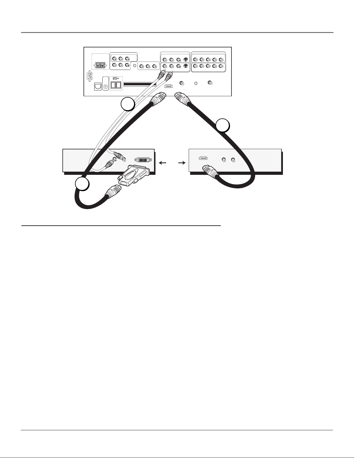
How to Connect: TV + Component with DVI or HDMI
High-Definition Multimedia Interface (HDMI) is an uncompressed digital interface that carries both video and audio data by
way of an integrated mini-plug cable. Since HDMI is based on Digital Visual Interface (DVI), the jack on the back of your TV
is compatible with DVI components.
1. To connect your TV to a component with a DVI jack, use an HDMI cable and an HDMI/DVI adapter.
A. Connect the HDMI cable to the HDMI/DVI INPUT jack on the back of the TV. Attach the HDMI/DVI adapter to the
end of the HDMI cable, then connect the adapter to the DVI Out jack on the back of the component.
B. Since you’re using an HDMI/DVI adapter, you need to connect Audio left and right cables to the R and L jacks on the
back of the component and to R and L Audio jacks that aren’t in use on the back of the TV.
C. Go to the DVI Audio Input option in the Audio Connections menu to select which Audio Input you’re using.
2. To connect your TV to a component with an HDMI jack, use an HDMI cable.
Connect the HDMI cable to the HDMI/DVI INPUT jack on the back of the TV and to the HDMI Out jack on the back of
the component.
Viewing the Component
1. Turn on the TV and the component you want to view.
2. Press the TV button on the remote control.
3. Repeatedly press the INPUT button on the remote control until the HDMI/DVI Video Input Channel is selected.
Note: You can set up the TV to automatically tune to the correct Video Input Channel. This is called Auto Tuning.
(See Chapter 3 for more information.)
18 Chapter 1
Connections & Setup
TV
CENTER SPEAKER INPUT
EXTERNAL AMP
MAX POWER RATING!
(60 WATTS into 8 OHMS)
POWER
(AC 120V~60Hz)
DIGITAL
AUDIO
ETHERNET
OUTPUT
FIXED/VARIABLE AUDIO OUTPUTS
CENTER
R REAR
R
SUBWOOFER
L REAR
L
MATRIX
SURROUND
OUTPUTS
WIRED
IR
CableCARD™
R
AUDIO/VIDEO
OUTPUT
R
L
V
R
HDMI/DVI INPUT
Use menu for DVI audio.
Card
Digital Cable
COMPOSITE INPUTS
INPUT 3
L
L
INPUT 1
V
S-VIDEO
S-VIDEO
V
CABLE
INPUT
R
R
For Factory Use Only
COMPONENT/COMPOSITE INPUTS
Use menu for composite video.
INPUT 4
L
R
P
P
B
L
P
R
P
B
INPUT 2
ANTENNA INPUT
Y/VIDEO
Y/VIDEO
CABLE
OR
OFF-AIR ANTENNA
FCC Statement: This digital television is capable of receiving analog basic, digital basic
and digital premium cable television programming by direct connection to a cable system
providing such programming. A security card provided by your cable operator is required
to view encrypted digital programming. Certain advanced and interactive digital cable
services such as video-on-demand, a cable operator’s enhanced program guide and dataenhanced television services may require the use of a set-top box. For more information,
call your local cable operator.
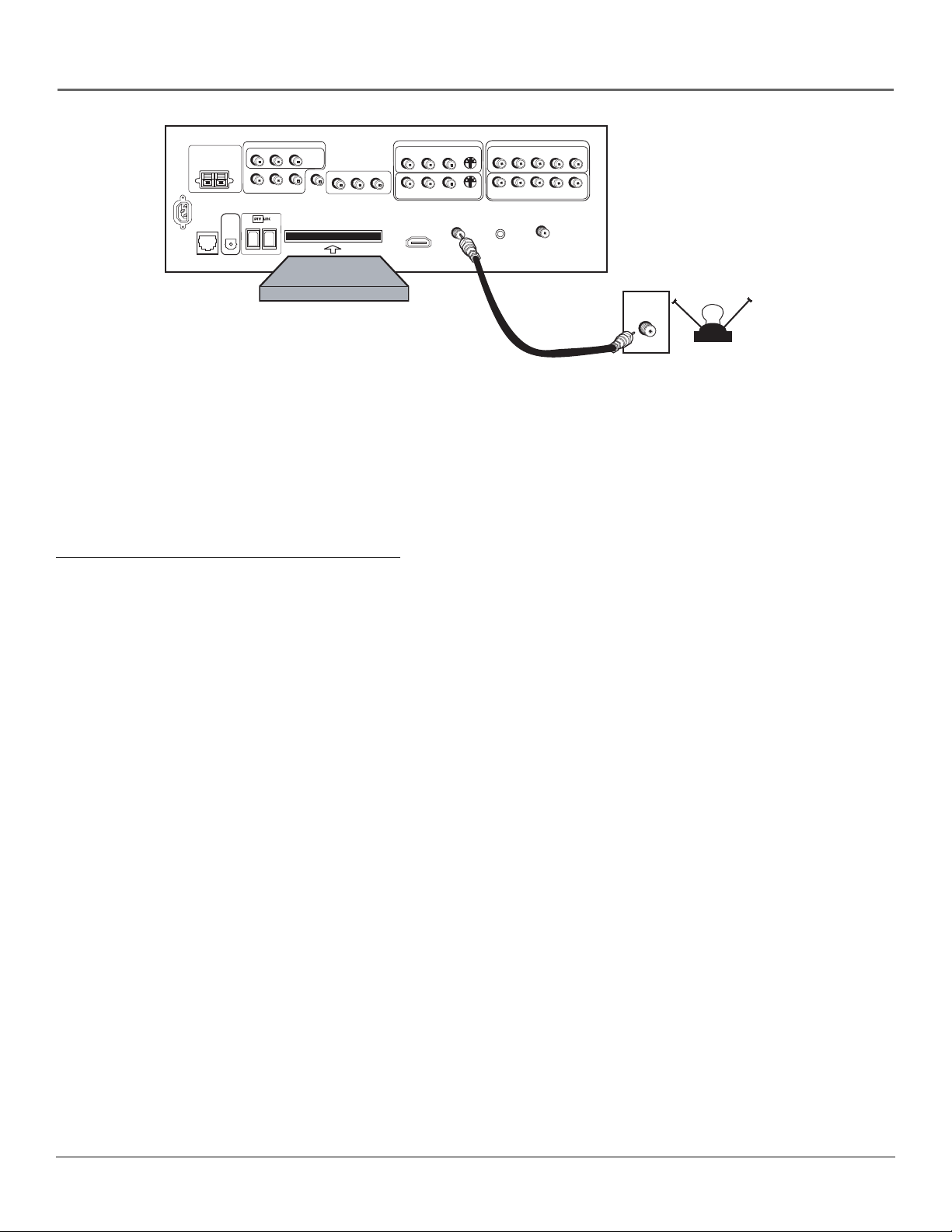
How to Connect: TV + CableCARD
The CableCARD slot allows you to use a digital cable television card to receive digital cable services, including premium and
HDTV cable channels, without the need for a set-top box. Please contact your local cable company for availability of services
and to obtain a digital cable television card.
When you receive the digital cable card, make sure you connect your coaxial cable to the CABLE INPUT jack. Then, turn on
your TV. Insert the digital cable card into the slot on the back of the TV labeled CableCARD. Push firmly on the card until
almost the entire card is inserted. Wait to receive information on-screen regarding your digital cable television services. See
below for information on setting up digital cable television services for your TV.
You should know:
• Once the digital cable card is authorized for a particular TV, the card can’t be used with any other TV, unless it is reauthorized to it.
• You won’t receive digital cable channels if you connect your cable to the ANTENNA INPUT. Make sure you connect
your cable to the CABLE INPUT.
• Once inserted, it is not recommended you remove the digital cable card. In the case it needs to be removed, grasp
firmly, and pull the card straight out.
Setting Up Digital Cable Television Service
Once you have connected a digital cable card to the CableCARD slot on the back of the TV (explained above), you are
ready to receive digital cable channels. Wait approximately 30 seconds for the status screen to appear. Write down the
information you see and call your cable company to provide them with the information on-screen.
Notes: If your information screen disappears before you have a chance to write down the information, press MENU
on the remote to access the menu system. Then press 9, 9, 9, and the information screen appears. Go to page 63 for
more information on the CableCARD Tools menu.
You can’t order video-on-demand through your digital cable card. Call your local cable company to place an order.
Chapter 1 19

Connections & Setup
Audio Connections
With the audio versatility of your HDTV, you can choose various connection options depending on the type and quality of
sound that you want. From good to best sound, choose one of the options or refer to the user’s manual of each component
that you are connecting to get the best results.
• Use your TV’s internal speakers (good sound).
• Connect audio/video receiver (speakers connected to receiver) to your TV (better sound).
• Connect audio/video receiver (speakers connected to receiver) using the digital audio output jack to your TV (best sound).
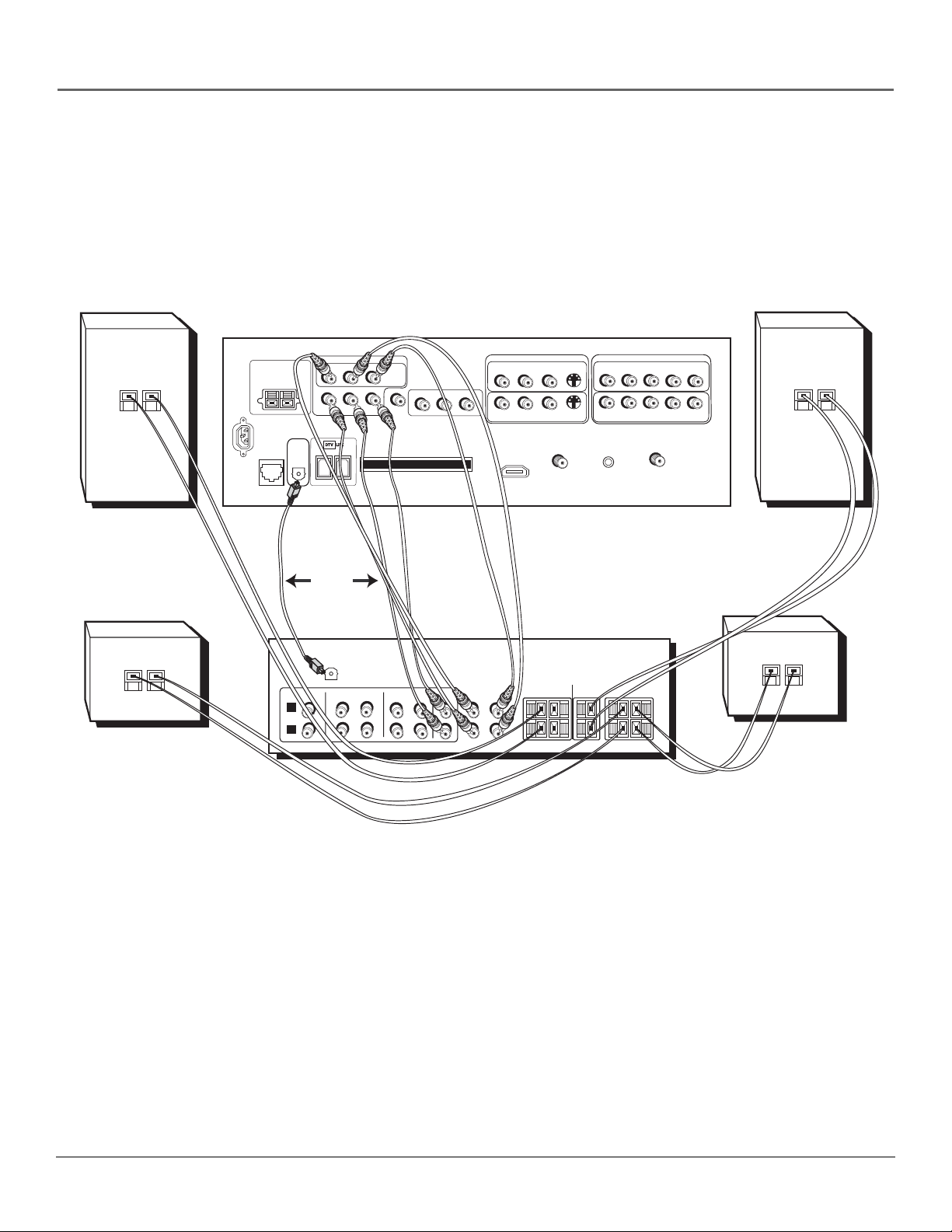
How to Connect: TV + A/V Receiver + Speakers
1. Connect the FIXED/VARIABLE AUDIO OUTPUTS from the TV to an A/V receiver using audio cables for 6-channel
matrix surround sound.
2. Be sure to go to the Fixed/Variable Out screen in the Audio Connections menu and select whether you want the
FIXED/VARIABLE AUDIO OUTPUT jacks to send fixed volume audio or variable volume audio.
• Fixed Output provides fixed-level audio output from the TV. This audio output is ideal for connecting to an A/V
receiver that has its own volume control.
• Variable Output provides variable-level audio output. Volume levels are controlled by the volume controls on
the TV and TV remote control.
3. If you connect the SUBWOOFER jack, be sure to go to the Fixed/Variable Out screen in the Audio Connections menu
and select Yes for connecting to an external subwoofer.
4. Use speaker wire to connect the Audio/Video receiver to external front and rear speakers. Refer to your audio receiver
manual to complete speaker hookup to the receiver.
OR
How to Connect: TV + Receiver with Dolby Digital +Speakers
If you own a receiver with Dolby Digital* and/or PCM (Pulse-Code Modulation) that uses an optical cable-type input, connect
an optical cable for excellent audio quality (shown on opposite page).
1. Connect one end of the optical cable to the DIGITAL AUDIO OUTPUT jack on your TV to the Digital Optical Input jack
on your receiver/amplifier receiver.
• If your receiver can decode Dolby Digital and PCM, go to Audio menu, select Audio Connections, then Digital
Audio Output. Select AutoSelect (recommended) or PCM option.
• If your receiver can decode only PCM, select PCM option.
2. Use speaker wire to connect the Audio/Video receiver to external front and rear speakers. Refer to your audio receiver
manual to complete speaker hookup to the receiver.
Note: If you want to use your TV’s internal speakers as the Center Channel speaker, use speaker wire to connect the
audio receiver’s CENTER SPEAKER OUTPUT to the TV’s CENTER SPEAKER INPUT. Set the Center Speaker Input option
in the Audio Connections menu to The center channel output from an audio receiver option.
*Manufactured under license from Dolby Laboratories. “Dolby” and the double-D symbol are trademarks of Dolby Laboratories.
20 Chapter 1
Connections & Setup
+
–
Back of Right Front Speaker
–
+
–
Back of Right Rear Speaker
TV
CENTER SPEAKER INPUT
EXTERNAL AMP
MAX POWER RATING!
(60 WATTS into 8 OHMS)
POWER
(AC 120V~60Hz)
DIGITAL
AUDIO
ETHERNET
OUTPUT
L
R
FIXED/VARIABLE AUDIO OUTPUTS
CENTER
SUBWOOFER
OR
CD
IN
IN
R REAR
DIGITAL
AUDIO
INPUT
COMPOSITE INPUTS
L REAR
MATRIX
SURROUND
OUTPUTS
WIRED
R
L
IR
CableCARD™
AUDIO/VIDEO
OUTPUT
R
L
V
INPUT 3
R
L
R
L
HDMI/DVI INPUT
Use menu for DVI audio.
INPUT 1
V
S-VIDEO
S-VIDEO
V
CABLE
INPUT
R
R
For Factory Use Only
COMPONENT/COMPOSITE INPUTS
Use menu for composite video.
INPUT 4
L
P
R
P
B
L
R
P
P
B
INPUT 2
ANTENNA INPUT
Y/VIDEO
Y/VIDEO
+
–
Back of Left Front Speaker
A/V AMPLIFIER
CENTER
SURROUND SPEAKERS
REAR
RIGHT
LEFT
+
–
Back of Left Rear Speaker
TAPE
VCR
OUT
IN
OUT
Surround
TV
CENTER
IN
FRONT SPEAKERS
RIGHT
SL
LEFT
+
–
SUBWOOFER
SR
+
–
Chapter 1 21
Connections & Setup
Router Cable Modem/DSL Internet
TV
Note: A computer is necessary if
you want to display photos or
graphics on your TV that are
stored on your computer. Refer
to www.rca.com/Access
Scenium/311 for more
information on viewing photos.
Computer
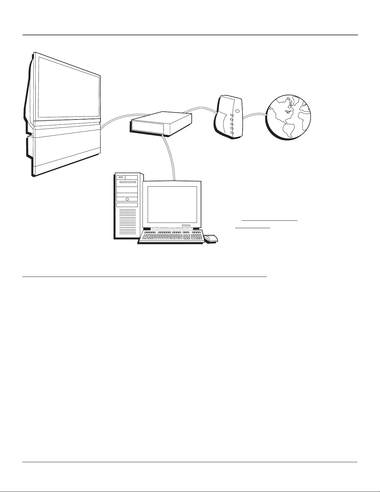
How to Connect: TV + Router via the HDTV’s ETHERNET Jack
The illustration above provides you with a general connection to the TV’s ETHERNET jack so you can maximize your
HDTV’s browser to surf the Internet. You don’t need to connect a computer to surf the Internet. A computer is only needed
if you want to view photos or graphics on your TV that are stored on your computer (then you don’t need cable modem/
DSL or Internet access). An Internet Service Provider subscription is necessary to access the Internet.
You should know:
• Only use the Ethernet connection if you are connecting a router to the TV’s ETHERNET jack.
• It is highly recommended that the router have DHCP capability.
• Only use this connection if you have purchased the keyboard designed for this HDTV (page 79 has ordering
information) because a keyboard is needed to effectively surf the Internet via your HDTV’s internal web browser.
• A router enables you to network several components, such as a computer, cable modem, or DSL modem. You’ll need to
set up each component that is connected to the router. Use the manuals that accompany your router and other Internet
components for specific instructions.
To connect the router to the TV, use a CAT5 cable (not provided) to connect the ETHERNET Input Jack on the back of your
HDTV to the ETHERNET Output Jack on the router.
The complexity of the setup required to make all of the components and the router work with your HDTV depends upon
your Internet Service Provider (ISP). Most ISPs will automatically fill in the information needed during setup, but if you are
asked for specific information while setting up the router and other components you will need to contact your ISP. Go to
the Ethernet Setup menu on page 63 for more information on the Ethernet setup.
22 Chapter 1
Connections & Setup
Plug in the TV
Plug the flat end of the power cable into the power jack on the back of the TV. Then plug the
other end of the power cord into an appropriate wall outlet. Be sure to insert the plug
completely. Do not plug into an outlet controlled by a light switch.
Note: When you first plug your TV into an outlet, the Power indicator on the front panel
will light and blink for approximately 30 seconds and then go off during the initialization
of the TV. The TV can only be turned on after the Power indicator goes off. This happens
every time the TV is unplugged and plugged back in.
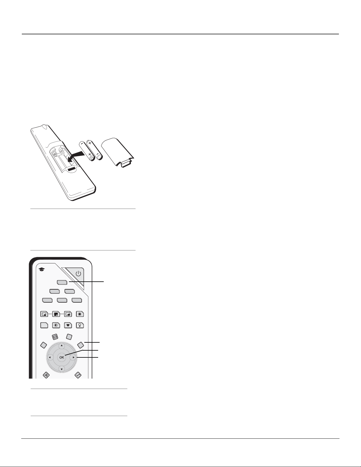
Put Batteries in the Remote
• Remove the battery compartment cover from the back of the remote
by pushing down on the tab and lifting cover.
• Insert 2 fresh “AA” batteries. Make sure the polarities (+ and -) are
aligned correctly with the polarities inside the remote.
• Replace the cover.
Tip
When remote batteries are low, the component
button(s) corresponding to the mode you’re in
flashes when you press a button. Also, a message
might appear on the TV screen and disappear
within a few seconds. Press CLEAR and replace the
batteries to remove the message.
ON-OFF
learning
TV
button
MENU button
SAT
/
CAB
PIP
PRESETS
CC
CCCC
FORMAT INFO
CLEAR
CC
TV
DVD VCR
AUX
SWAP
CH. CTRL
FAV
AUDIO
FREEZE
LIGHT
i
MENU
MM
OK button
Arrow
SOUND
SKIP
buttons
Turn on the TV
Press TV on the remote, or press the Power button on the TV’s front
panel.
Note: Pressing the TV button turns on the TV and puts the remote
into TV mode. “TV mode” means that the buttons on the remote
control operate the TV’s functions.
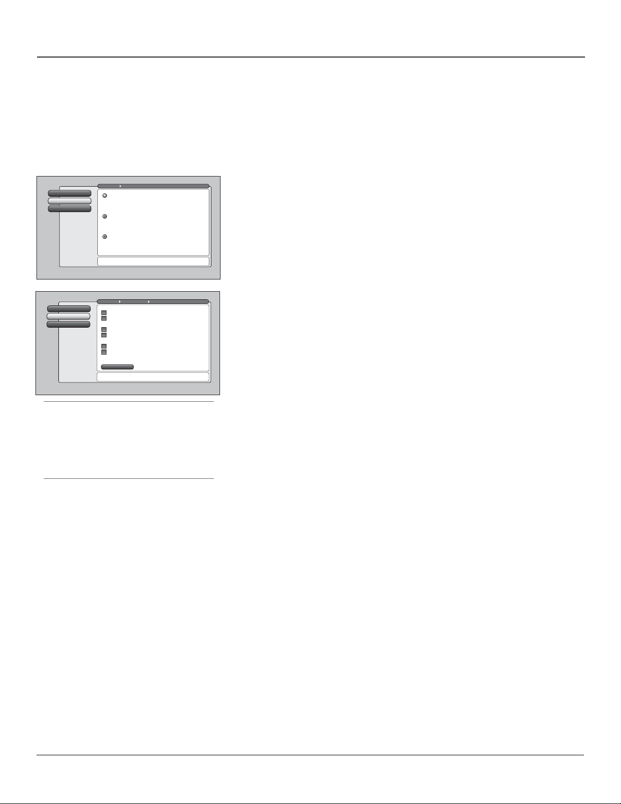
Use the Remote Control to Complete
the Assisted Setup
The technical term is “Navigation” – how you move through the on-screen
menus. The method is the same throughout the menu screens: highlight
your choice and select it.
To highlight a menu item, put the remote into TV mode by pressing the
TV button then MENU. Press the arrow buttons on the remote to highlight
one of the items listed in the menu. Use the up or down arrow button to
move up or down. Use the right or left arrow button to move right or left.
To select the item that you’ve highlighted, press OK.
Note: Highlighted means that the menu item stands out from
other menu items on the list (appears darker, brighter, or a
different color).
Tip
To access the setup menus, press MENU and
choose Assisted Setup.
Chapter 1 23
Connections & Setup
Complete the Assisted Setup
Your TV’s menu system allows you to adjust your TV’s features to be configured to work
properly. On-screen information helps you choose settings to match your setup. The first time
you turn on your TV, the Assisted Setup screens appear automatically. Select Begin Setup to start
or select Cancel Setup to exit.
Go Back
0
Closed CaptioningContinue Setup
1
Cancel Setup
2
Go Back
0
Continue Setup
1
Cancel Setup
2
Main Menu Preferences
English
Highlight with the and arrows. Select with the OK button.
Español
Resalte con las flechas y . Seleccione con el botón OK.
Français
Mise en surbrillance avec et . Sélection avec OK.
Press or to point to an option, then press OK to
select it. Press to return to the menu.
Main Menu Assisted Setup
Input to search:
Cable Input
Antenna Input
Channels to search:
Digital channels
Analog channels
Other search options:
Detect antenna or cable setting
Include previously found channels in search
Start
Pressto make changes to this screen's settings.
Press OK to skip to the next step in the setup routine.
Channel Search
Channel Search finds channels
for you. Check fewer boxes to
make the search faster (but
less complete) and vice versa.
The first time that you do a
Channel Search, put a check in
all the boxes to do a thorough
search for channels.
To add a channel that Channel
Search didn't find, clear all
menus and directly tune to the
channel with the number keys.
Tip
The first Channel Search takes several minutes if
the TV is searching for analog and digital
channels and cable and antenna inputs are
being searched. You may want to leave and
come back later.
Set the Menu Language
1. Use arrow buttons to highlight your preferred language for the
menu system.
2. Press OK to select that language.
3. Press the left arrow button and the up or down arrow button, if necessary,
to select Continue Setup, then press OK.
Complete Channel Search
Even though this initial channel search can take several minutes, it is important
to complete in order for your TV to display channels and programming. Make
sure you have connected cable and/or off-air antenna to the corresponding
inputs before you start channel search.
1. To do a complete channel search, check each box that pertains to your TV.
For example, if you’re only receiving cable from the CABLE INPUT,
highlight Cable Input and press OK to place a checkmark in the box.
2. Select Start to begin the search.
3. When the channel search is complete, a message screen appears. Select
Continue. Another message screen appears telling you that you’ve
completed the Assisted Setup. Select Continue on the left.
Notes: If you skip Channel Search now, you can access it later through
the Connections menu. See Chapter 4 for more details.
If a cable box is connected to your TV’s CABLE INPUT, or a CableCARD
is in use, Channel Search won’t work for Cable Input.
24 Chapter 1

Chapter 2
Using the Remote Control
Chapter Overview:
• The Buttons on the Remote Control
• Programming the Remote to Operate Other Components
• How To Use the Remote After You’ve Programmed It
• The Learning Feature
• Volume Punchthrough Feature
• Using the INPUT Button
• Remote Code List
Graphics contained within this publication are for representation only. 25
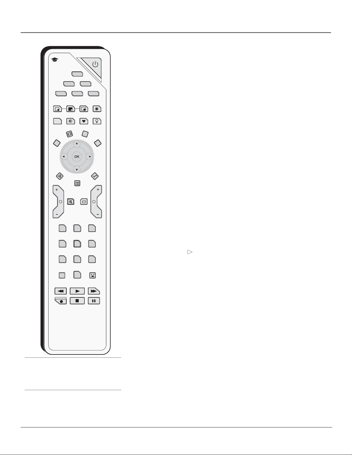
Using the Remote Control
learning
SAT
/
CAB
PIP
CC
CCCC
FORMAT INFO
CLEAR
CC
SOUND
VOLVOL
11
44
77 88
INPUTINPUT
ININ
TV
DVD VCR
AUX
SWAP
CH. CTRL
PRESETS
GUIDE
MUTEMUTE GO
BACKGOBACK
22
55
00
PLAYPLAY
FAV
ON-OFF
AUDIO
i
33
66
99
ANT•CAB
FORWARDFORWARDREVERSEREVERSE
FREEZE
LIGHT
MENU
MM
SKIP
CH
The Buttons on the Remote Control
Arrows (up, down, left, right) Used to move through the on-screen menus.
Also moves the PIP window, see page 46 for more information.
(0-9) Number Buttons Enter channel numbers and time settings.
ANT•CAB Switches between Antenna and Cable Input. In VCR mode,
functions as a TV/VCR button. In SAT mode, functions as a TV/SAT button for
an RCA satellite receiver. When tuned to an input, press to go back to the most
recently used tuner (Antenna or Cable Input).
AUDIO Places the remote in audio mode to operate a component (such as a
audio receiver, CD player, or amplifier receiver) that you’ve programmed to
work with this button.
AUX Places the remote in auxiliary mode to operate a component (such as a
cable box, satellite receiver, VCR, DVD, or audio receiver) that you’ve
programmed to work with this button. AUX by default is set up for a second
RCA VCR.
CC (Closed Captioning) Toggles closed captioning on and off, if available
for the channel you’re tuned to. When you change channels or inputs, the
default for Caption Display is restored.
CH + or CH – Scrolls up or down through the channel or input list. Press
once to change the channel up or down; press and hold to continue changing
channels.
CH CTRL (Channel control) Toggles the channel control between the main
TV picture and the PIP window. Use channel up, channel down, INPUT,
component buttons, or number buttons to change channels in PIP. CH CTRL is
marked by a triangle ( ) in the banner.
CLEAR Removes on-screen menus and displays. Cancels the commercial skip
timer. Quits the browser.
DVD Places the remote in DVD mode. If Auto Tuning is enabled, pressing the
DVD button turns on the TV and tunes to the correct Video Input Channel.
FAV (Favorite) Press this button and a number button (0-7) to activate a
STOPSTOP
PAU SEPAUS ERECORDRECORD
favorite webpage. See Using the Web Browser for more information.
FORMAT Toggles through the 4:3 video screen formats (Normal, Zoom,
Stretch, Cinerama, and Auto Format) for some 4:3 signals—not applicable to
16:9 signals. In browser mode, toggles through three different modes: fullscreen browser, video window on the left, and video window on the right.
FREEZE Freezes entire screen, including the main picture and PIP window, if
PIP is displayed. When recording from AUDIO/VIDEO OUTPUT, freezes digital,
Tip
Some remote buttons can be used with the
Web Browser and have different functions; see
page 49 for details.
but not analog channels. Does not affect DTVLink output.
GO BACK Returns you to the previous channel or previous screen in the
menu system. Also, toggles between tuner and input sources.
GUIDE If you’re controlling another component that has a guide, this accesses
the on-screen guide.
26 Chapter 2

Using the Remote Control
Tips
The component button corresponding to the
mode you’re in flashes when the remote
batteries are low and you press a button on the
remote. A warning banner may also appear on
the screen when you press a remote button and
your batteries are low.
To turn off most RCA components that are
connected to the TV, press ON•OFF twice within
two seconds and hold remote steady until
indicator turns off.
INFO Brings up the Channel Banner with channel and viewing information.
Press again to remove the banner.
INPUT Toggles through the TV’s available input sources (INPUT 1, INPUT 2,
INPUT 3, INPUT 4, Front Input, HDMI/DVI, DTVLink and last-active channel).
To quickly access an input, press the INPUT button and the input number, for
example, INPUT + 1 to access INPUT 1.
LIGHT Press to illuminate the remote control’s buttons. To conserve battery
power, the light turns off after several seconds. Backlight won’t activate if
batteries are low, but blinks on and off quickly.
MENU Makes Main Menu appear and disappear.
MUTE Reduces the TV’s volume to its minimum level. Press again to restore volume. The TV Audio Output menu
must be set to Variable Level, Speakers On to control the TV’s volume.
OK When a menu item is highlighted, press OK to select the item.
ON•OFF Turns the TV on or off. Your HDTV is equipped with a special lamp system. In order to preserve the life
of the lamp, the TV must warm up and cool down properly when you turn the TV on and off. When you turn the TV
off, the screen turns blue and fades to black. While the screen is blue, you can still turn the TV back on. If the screen
is black when you try to turn it on, the TV’s lamp is in its cool-down cycle. The TV’s audio comes on, then the
picture is displayed after a few moments.
In other modes (VCR, DVD, SAT/CAB, AUX, AUDIO), and if programmed, turns the component on and off.
PIP Makes the PIP window appear and disappear (See Chapter 3 for more information about using PIP.)
PRESETS Toggles through the Picture Presets for the input currently tuned to. The preset is only temporarily
changed and goes back to the original menu setting when you change channels or inputs or turn off the TV.
REVERSE, PLAY, FORWARD, RECORD, STOP, PAUSE If programmed, provides transport control for some remotecontrollable VCRs and CD and DVD players. In TV mode, can control a DTVLink component when tuned to the
DTVLink input.
SAT/CAB (Satellite/Cable) Places the remote in SAT/CAB mode. If Auto Tuning is enabled, turns on the TV and
tunes it to the correct Video Input Channel.
SKIP Press once before changing channels and the TV returns to the original channel after 30 seconds. Press
repeatedly to add more time. Press CLEAR to cancel.
SOUND On digital channels/inputs, toggles the audio mode (if available for that channel). For analog channels,
toggles SAP on or off. If you change channels/inputs, the default for Audio Mode or SAP is restored. Does not affect
default menu settings for SAP or Audio Mode.
SWAP When using PIP, switches the main picture with the PIP window.
TV Places the remote in TV mode. Turns on the TV and tunes to the last-viewed TV channel or input.
VCR Places the remote in VCR mode. If Auto Tuning is enabled, turns on the TV and tunes to the VCR Video Input
Channel.
VOL – or VOL + Decreases or increases the TV’s volume. The TV Audio Output menu must be set to Variable
Level, Speakers On to control the TV’s volume.
Chapter 2 27
 Loading...