

HDTV with DLP technology
High Definition Television
User's Guide

Important Information
WARNING
To reduce the risk of fire or
electric shock, do not expose
this product to rain or
moisture.The apparatus shall
not be exposed to dripping or
splashing and no objects filled
with liquids, such as vases, shall
be placed on the apparatus.
Refer to the identification/rating label located on the back panel of your product for its proper operating voltage.
FCC Regulations state that unauthorized changes or modifications to this equipment may void the user’s authority
to operate it.
Cable TV Installer: This reminder is provided to call your attention to Article 820-40 of the National Electrical
Code (Section 54 of the Canadian Electrical Code, Part 1) which provides guidelines for proper grounding and, in
particular, specifies that the cable ground shall be connected to the grounding system of the building as close to
the point of cable entry as practical.
Warning: The apparatus shall not be exposed to dripping or splashing and that no objects filled with liquids, such
as vases, shall be placed on the apparatus.
Important: This television is a table model and is designed to sit on a firm, flat, surface. Don't place the TV on soft
carpeting or similar surface because the ventilitation slots on the bottom of the unit will be blocked resulting in
reduced lifetime from overheating. To assure adequate ventilation for this product, maintain a spacing of 4 inches
from the top and sides of the TV receiver and 2 inches from the rear of the TV receiver and other surfaces. Also,
make sure the stand or base you use is of adequate size and strength to prevent the TV from being accidentally
tipped over, pushed off, or pulled off. This could cause personal injury and/or damage the TV. Refer to the
Important Safety Instructions packed separately.
CAUTION
RISK OF ELECTRIC SHOCK
DO NOT OPEN
This symbol indicates
"dangerous voltage" inside
the product that presents a
risk of electric shock or
personal injury.
Caution: To reduce the risk of electric shock, do
not remove cover (or back). No user serviceable
parts inside. Refer servicing to qualified service
personnel.
This symbol indicates
important instructions
accompanying the product.
Product Registration
Please fill out the product registration card (packed separately) and return it immediately. Returning the card
allows us to contact you if needed. For U.S. customers: Your RCA Scenium Consumer Electronics product may also
be registered at www.rcascenium.com/productregistration. Returning the card allows us to contact you if needed.
Product Information
Keep your sales receipt to obtain warranty parts and service and for proof of purchase. Attach it here and record
the serial and model numbers in case you need them. These numbers are located on the product.
Model No. ______________________________________________________________________________________________
Serial No ._______________________________________________________________________________________________
Purchase Date: __________________________________________________________________________________________
Dealer/Address/Phone: ___________________________________________________________________________________
VCR Plus+, C3, PlusCode, G-LINK, and GUIDE Plus+ are trademarks of Gemstar-TV Guide International, Inc. and/or its
related affiliates. Patent 6,331,877; 6,239,794; 6,154,203; 5,940,073; 4,908,713; 4,751,578; 4,706,121; 6,466,734;
6,430,359; 6,091,882; 6,049,652; 5,335,079; 5,307,173.
The VCR Plus+ and GUIDE Plus+ systems are manufactured under license from Gemstar-TV Guide International, Inc.
and/or its related affiliates.
THOMSON INC. AND GEMSTAR-TV GUIDE INTERNATIONAL AND/OR ITS RELATED AFFILIATES ARE NOT IN
ANY WAY LIABLE FOR THE ACCURACY OF THE PROGRAM SCHEDULE INFORMATION PROVIDED BY THE
GUIDE PLUS+ SYSTEM. IN NO EVENT SHALL THOMSON INC. OR GEMSTAR-TV GUIDE INTERNATIONAL BE
LIABLE FOR ANY AMOUNTS REPRESENTING LOSS OF PROFITS, LOSS OF BUSINESS, OR INDIRECT, SPECIAL,
OR CONSEQUENTIAL DAMAGES IN CONNECTION WITH THE PROVISION OR USE OF ANY INFORMATION
EQUIPMENT, OR SERVICES RELATING TO THE GUIDE PLUS+ SYSTEM.
VCR required for recording.
Introduction
Thank you for choosing RCA Scenium
Congratulations on purchasing this RCA Scenium High Definition Television (HDTV) featuring DLP™
(Digital Light Processing™) technology—a true viewing experience. Your purchase decision represents an
investment in a new generation of technology— DLP™ and HDTV. Even though this is a technologically
advanced HDTV, it is the most user-friendly of its kind— with comprehensive on-screen instructions that
guide you through all of the TV’s features.
This introduction describes three reasons why an RCA Scenium HDTV featuring DLP™ technology is an
excellent choice:
DLP™—brilliance in color, design, and technology
Why RCA Scenium DLP™ is better?
Other Key Features of owning an RCA Scenium HDTV
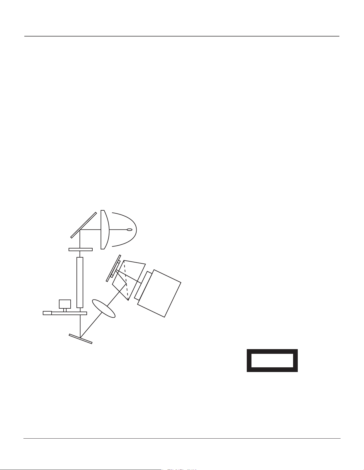
Part 1: DLP™— brilliance, in color, design, and technology
RCA Scenium brings you brilliant pictures with Digital Light Processing™ system (DLP™) — a brilliantly
choreographed, engineering marvel that combines microscopic mirrors, light, and color to bring you the
best and brightest pictures possible.
Condenser Lens
Fold Mirror
Arc Lamp
UV/IR Filter
Light Pipe
Color Wheel
Fold Mirror
TM
DMD Chip
with DMD
Window
Assembly
Relay Lens
TIR Prism
Projection Lens
Lamp Replacement
DLP technology uses a special lamp. Eventually, you’ll need to
replace this lamp. To order the correct lamp, you’ll need to know
your TV’s model number, serial number, and lamp type—this
information is listed on the Service Model Number sticker (example
of the sticker is shown at right). The sticker is located on the right
side of the TV. For quick reference, write down the information in
the space provided at the right.
How DLP™ Works
In general, DLP™ combines microscopic mirrors, a
specially designed semiconductor, and a color wheel
to adjust light to display the most brilliant, accurate
images! Your DLP™ HDTV doesn’t use Cathode Ray
Tubes (CRTs), which means you don’t have to worry
about screen burn (fixed video images burning onto
the screen permanently) or convergence (realigning
the CRTs). The diagram on the left illustrates the
complex system.
Thin and Light
The efficiency of DLP™ technology enabled our
design team to create a high-performance HDTV that
is about 16 inches thin and weighs less than 100
pounds.
Service Model Number Numéro de Modéle-Service
HDLP50XXXXXX
000000000 X
SERIAL SERIE LAMP
EXAMPLE: Service Model Number sticker
with lamp type listed.
Model No.____________________________________
Lamp Type___________________________________
Date_________________________________________
Digital Light Processing, DLP and DLP Cinema are trademarks of Texas Instruments. All other products and names may or may not be
trademarks or registered trademarks of their respective companies.
1
Introduction
Part 2: Why RCA Scenium DLP™ is better?
DLP™ is just part of the story. You have chosen to embark on the next generation of TV viewing— HDTV. There are many
technological advancements that make HDTV better than analog TV, but there are basically three things about HDTV that
bring you a superior viewing experience: (1) resolution, (2) aspect ratio, and (3) digital signal and sound.
Resolution (it’s math...that works for you)
The crisp, lifelike picture people rave about when experiencing true HDTV is due to the resolution this technology
provides. The resolution is measured by calculating the number of active lines of pixels. A pixel (which stands for picture
element) is a small dot. The picture you see on your TV is composed of these dots.
A regular, analog television (called analog) only has a resolution of about 200,000 pixels (480 vertical pixels x 440 horizontal
pixels = 211,200 pixels). The HDTV format is capable of more than 2 million pixels (1,920 x 1,080 = 2, 073,600).
More pixels equals more detail. In summary, HDTV is capable of resolution that is up to 10 times the resolution of the
picture on a regular, analog TV!
Format Analog (NTSC) HD Digital (ATSC)
Total Scan Lines 525 1125
Effective Scan Lines 480 1080
Aspect Ratio 4 : 3 16 : 9
Max Resolution 720 x 480 1920 x 1080
Sound 2-ch Stereo 5.1 ch Surround
16:9 Aspect Ratio
4:3 Aspect Ratio
Aspect Ratio
Aspect ratio is simply the width and height of the picture. Regular TVs use a
4 x 3 (also written 4:3) aspect ratio, which means the picture is a little wider
than it is tall (a screen that is 20 inches wide is about 15 inches tall).
When the standards were being developed for television broadcasting in
1941 by the NTSC (the National Television Standards Committee), it made
sense to adopt the 4 x 3 aspect ratio that the film industry was using at that
time.
As TVs dropped in price and people prospered in the 1950s, the movie
industry had to find a way to get people out of their living rooms and back
to the movie theatres. That’s when they created the 16 x 9 (also written 16:9)
aspect ratio (also called widescreeen format). When the standards for HDTV
were being developed by the ATSC (Advanced Television Standards
Committee), the 16 x 9 aspect ratio was chosen as the format for HDTV.
This widescreen format makes sense because it’s much closer to the way we
see. Our field of vision is actually much wider than tall because of our
peripheral vision. Not only is it closer to the way we see, but the pictures are
crisper and cleaner with more detail in the close-up and panoramic views.
2

Introduction
Digital Signal and Sound
The analog television broadcast system that has been used in the United States for the past 50 years transmits signals as
electronic waves. These waves can suffer degradation as the signal travels to your home. Additionally, the analog waves are
susceptible to interference from planes passing overhead, weather, and household appliances.
Digital signals, in contrast to analog signals, can be reproduced precisely because the images are transmitted and received
using the computer language of 1s and 0s. Such precision yields a signal that is capable of displaying studio-quality picture
and Dolby Digital 5.1 channel sound.
Part 3: Other Key Features of owning an RCA Scenium HDTV
There are other HDTVs on the market— even some that use DLP technology. But your RCA Scenium HDTV has been
designed with features that will enhance your TV viewing, and features that provide flexibility to build on the digital
revolution that is taking place. A summary of your TV’s most unique features follows. Chapter 3 provides more detail about
these features and information about additional features.
Integrated HDTV Tuner with QAM
RCA was the first to offer an integrated tuner with its HDTVs (no need for a set-top box to receive digital programming).
Now, we’ve gone one better— your HDTV’s tuner is ready for digital cable (no need for a cable box to view unscrambled,
digital cable, programming). The tuner is able to decode all 16 formats of digital television broadcasts and it can interpret
digital cable signals because it includes the ability to decode QAM (Quadrature Amplitude Modulation) encoded
programming.
Note: A cable box may be necessary to view scrambled and/or premium channels. Contact your cable provider for
more information.
TruScan Digital Reality
Optimum picture performance occurs when the picture intended is the picture presented. TruScan Digital Reality intelligent
signal processing recognizes incoming video signals and progressively converts them to achieve optimum digital picture
performance. It also recognizes when original film sources have been modified and automatically converts the analog frame
rate back to its original format to bring out the detail—a process commonly referred to as reverse 3:2 pulldown.
User-friendly Features Help You Personalize Your TV
•You can customize your TV to fit your viewing taste and match the lighting
where you watch TV by using Personal Presets and/or the automatic picture
quality settings: Vibrant, Natural, and Cinematic. You can adjust different
Input Jacks to different settings and the TV will automatically adjust the
picture accordingly.
• Help Text: The elaborate, on-screen help describes your TV’s features and
explains how to use them.
• GUIDE Plus+ System: The on-screen programming guide helps you
navigate through hundreds of channels so you can quickly see what’s on
and tune directly to a specific show from the guide! You can use the Sort
feature to search listings. You can even set up reminders to watch a certain
show via the GUIDE Plus+ system’s Watch menu.
3

Introduction
FireWire® with Two-Way DTVLink®
Control your IEEE-1394 components via your HDTV! Just link them together via the 2-way DTVLink jacks and you can
network your high-speed compatible 1394 digital components. The two-way jacks allow the audio and video signals to flow
into and out from the 1394 components, such as the DVR10 (see below).
Compatible with the Optional DVR10 Hard Disk Drive — Pause Live Digital TV and record digital programs
RCA offers an Audio Video Hard Disk Drive (model DVR10) with IEEE 1394, available at your local RCA dealer or
www.rca.com. The DVR10 Audio Video Hard Disk Drive (AVHDD) component lets you pause live TV, record shows, and
play them back (digital broadcasts only—ATSC and QAM signals).
NetConnect
With an Ethernet connection and a web browser built into your TV, you can
access the Internet from your TV*. To use the web browser, you’ll need a highspeed connection, such as a DSL (Digital Subscriber Line) unit or cable modem
and a subscription to an ISP (Internet Service Provider). DSL, cable modem, and
ISP subscription sold separately.
To get the most out of your HDTV’s web
browser, purchase the keyboard (model
KBR755TA1) designed specifically for your TV
(go to page 84 for ordering information).
Audio System
Enjoy the great sound system in your HDTV with 60 watts total power. Your HDTV has front speakers with two 1” tweeters
and two 5” midrange drivers to create incredible sound. A 7-band on-screen graphic equalizer allows customization of the
sound quality. TruSurround XT™ solves the problem of playing 6.1 multichannel content over two speakers. It delivers a
compelling, virtual, surround sound experience through any internal television speakers.
Record Output Jacks
Because the VCRs in most households are analog and can’t interpret digital signals, recording HDTV broadcasts wasn’t
possible without purchasing additional equipment. That’s why RCA added Record Output Jacks to this HDTV — the
RECORD OUTPUT with its AUDIO OUT L/R jacks enable you to record both analog and digital programs to an analog VCR.
RCA understands how you watch TV and what is necessary to make the transition to HDTV seamless.
CinemaScreen™
Check out the black, borderless frame around your HDTV’s screen. This is not just a design feature— the CinemaScreen
actually enhances contrast. Feel like you’re part of the picture with CinemaScreen.
*The browser has limitations and might not be able to interpret all files, such as
streaming audio and video.
What’s Next?
If you didn’t have your HDTV professionally installed, go to Chapter 1 for instructions. The rest of this User’s Guide explains
the features in more detail, the remote control, and the menu system.
Note: For U.S. customers: If you prefer, we can provide you with the name of an Authorized Service Representative
who will visit your home for a fee to install your electronics entertainment system and to instruct you in its operation.
For details about this service, call 1-888-206-3359.
DTVLink® Certification Logo is a U.S. registered mark of CEA.
FireWire is a trademark of Apple Computer, Inc., registered in the U.S. and other countries.
TruSurround XT, SRS and the (o) symbol are trademarks or registered trademarks of SRS Labs, Inc.
4

Table of Contents
Introduction
Key Features Overview ................................................................................................................... 1
Chapter 1: Connections & Setup
Things to Consider Before You Connect ........................................................................................ 8
Choose Your Connection ................................................................................................................. 9
How to Connect: TV + VCR + DVD Player ............................................................................. 10
How to Connect: TV + Satellite Receiver + VCR .................................................................... 11
How to Connect: TV + Receiver with Dolby Digital + Speakers ........................................... 12
How to Connect: TV + A/V/Receiver + Speakers + Use TV as Center Channel .................... 12
How to Connect: TV + Speakers Without A/V Receiver ....................................................... 14
How to Connect: TV + Router via the HDTV’s ETHERNET Jack ............................................ 15
How to Connect: TV + DTVLink® and/or 1394 Components ............................................... 16
How to Connect: TV + Set-top Box Using DVI-HDTV (Digital Visual Interface) .................. 17
Explanation of Input Jacks and Cables ........................................................................................ 18
Back of the TV ................................................................................................................................ 20
Why You Should Connect the G-LINK™ Cable ............................................................................ 23
How to Find the Remote Sensor ............................................................................................ 23
Placing the G-LINK Wands ..................................................................................................... 23
The Front of Your TV ..................................................................................................................... 24
Front Input Jacks..................................................................................................................... 24
Front Panel .............................................................................................................................. 24
Plug in the TV................................................................................................................................. 25
Put batteries in the remote........................................................................................................... 25
Turn on the TV ............................................................................................................................... 25
Use the Remote Control to Complete the Assisted Setup.......................................................... 25
Complete the Assisted Setup........................................................................................................ 26
Set the Menu Language ......................................................................................................... 26
Complete Channel Search ...................................................................................................... 26
The GUIDE Plus+ System™ Setup .......................................................................................... 26
What to Expect .............................................................................................................................. 30
Next Steps ...................................................................................................................................... 30
Chapter 2: Using the Remote Control
The Buttons on the Remote Control ............................................................................................ 32
Programming the Remote to Operate Other Components ........................................................ 34
How to Use the Remote After You’ve Programmed It ............................................................... 36
Volume Punchthrough Feature .....................................................................................................37
Using the Input Button ................................................................................................................. 38
Remote Code List ........................................................................................................................... 39
Chapter 3: Using the TV’s Features
About the Channel Banner ........................................................................................................... 42
Digital or Analog TV Channels ..................................................................................................... 43
About the GUIDE Plus+ System ....................................................................................................44
Parental Controls ........................................................................................................................... 48
How V-Chip Works for the USA and Canada ............................................................................... 49
Auto Tuning Feature ...................................................................................................................... 55
PIP (Picture-in-Picture) Operation ................................................................................................. 56
Using the Web Browser ................................................................................................................ 58
1394 Recording .............................................................................................................................. 59
5

Table of Contents
Chapter 4: Using the TV’s Menu System
Menus, On-screen Help, and Control Panels ............................................................................... 62
Picture Quality Menu .................................................................................................................... 64
Picture Settings ....................................................................................................................... 64
Picture Presets ......................................................................................................................... 64
Auto Color............................................................................................................................... 65
Color Warmth ......................................................................................................................... 65
Noise Reduction ...................................................................................................................... 65
Advanced Settings .................................................................................................................. 65
Reset Controls ......................................................................................................................... 66
Audio Menu ................................................................................................................................... 66
Equalizer Presets ..................................................................................................................... 67
Audio Processor ...................................................................................................................... 67
Sound Logic............................................................................................................................. 68
Audio Language ..................................................................................................................... 68
SAP (Second Audio Program)................................................................................................. 68
Balance .................................................................................................................................... 68
Fixed/Variable Out .................................................................................................................. 69
Digital Audio Out ................................................................................................................... 69
Time Menu ..................................................................................................................................... 70
Connections Menu......................................................................................................................... 70
Antenna Info........................................................................................................................... 70
Channel Search ....................................................................................................................... 71
Software Upgrade .................................................................................................................. 71
Signal Source........................................................................................................................... 71
Signal Type .............................................................................................................................. 71
Auto Tuning ............................................................................................................................ 72
1394 Setup .............................................................................................................................. 72
Special Features ...................................................................................................................... 72
Ethernet Setup ........................................................................................................................ 72
Preferences Menu .......................................................................................................................... 73
Closed Captioning .................................................................................................................. 73
Screen Format ......................................................................................................................... 74
Record Output ........................................................................................................................ 75
Color Scheme .......................................................................................................................... 75
Translucency ............................................................................................................................ 76
Menu Language...................................................................................................................... 76
Digital Channel Info ............................................................................................................... 76
Lamp Power ............................................................................................................................ 76
Chapter 5: Reference
Troubleshooting ............................................................................................................................. 78
HDTV Specifications ...................................................................................................................... 82
Accessory Information .................................................................................................................. 84
Limited Warranty........................................................................................................................... 87
Care and Cleaning ......................................................................................................................... 88
FCC Information ............................................................................................................................. 89
Index ............................................................................................................................................... 90
6

Chapter 1
Connections & Setup
Chapter Overview:
• Things to Consider Before You Connect
• Choose Your Connection
• How To Connect
• Explanation of Input Jacks and Cables
• Back of the TV
• Why You Should Connect the G-LINK Cable
• The Front of Your TV
• Plug in the TV
• Put Batteries in the Remote
•Turn on the TV
• Use the Remote Control to Complete
the Assisted Setup
• Complete the Assisted Setup
• What to Expect
• Next Steps
Graphics contained within this publication are for representation only. 7

Connections & Setup
Things to Consider Before You Connect
Protect Against Power Surges
• Connect all components before you plug any of their power cords into the wall outlet or power strip. NEVER plug
your TV into an outlet that is controlled by a wall switch.
•Turn off the TV and/or component(s) before you connect or disconnect any cables.
• Make sure all antennas and cables are properly grounded. Refer to the Important Safeguards sheet packed with
your TV.
Protect Components from Overheating
• Don’t block ventilation holes on any of the components. Arrange the components so that air can circulate freely.
• Don’t stack components.
• If you place components in a stand, make sure you allow adequate ventilation.
• If you connect an audio receiver or amplifier, place it on the top shelf so the heated air from it won’t flow around
other components.
Position Cables Properly to Avoid Audio Interference
• Insert each cable firmly into the designated jack.
Use Indirect Light
Don’t place the TV where sunlight or room lighting will be directed toward the screen. Use soft or indirect lighting.
Using a Stand
This television is a table model and is designed to set on a firm, flat surface. Placing the TV on soft carpeting or a like
surface can block the bottom ventilation slots and result in reduced lifetime due to overheating. Make sure the stand or
base you use is of adequate size and strength to prevent the TV from being accidentally tipped over, pushed off, or
pulled off. This could cause personal injury and/or damage the TV. Refer to the Important Safety Instructions packed
separately.
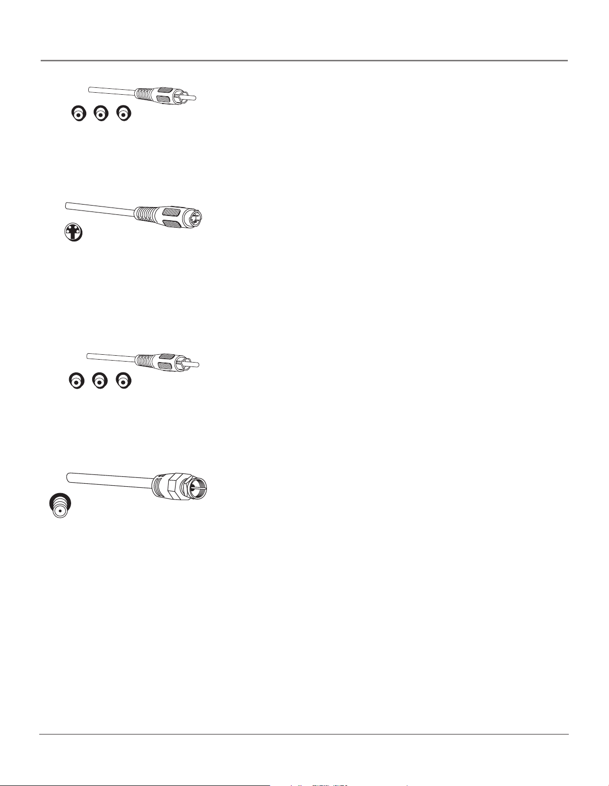
Cables You Need to Connect Components to Your TV
The pictures below show the cables (not supplied) you may need for the connections represented in this book.
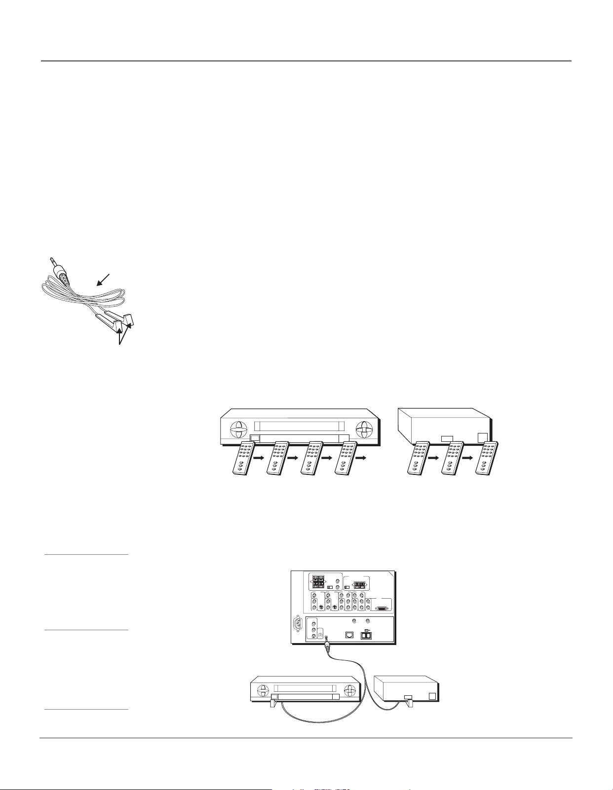
Note: Please locate the G-LINK cable (provided) when you’re getting ready to set up your TV. You need to connect
this cable to your TV and to your VCR and/or cable box in order for all of the features of the program guide to work
properly.
G-LINK cable
Coaxial cable DVI-D cable
S-Video cable
Ethernet Cable
Digital Optical Cable
A/V Cable
1394 Cable
Composite Video
Audio/ Video cable
Component Video
Y•Pb•Pr cable
Speaker Wire
8 Chapter 1
Connections & Setup
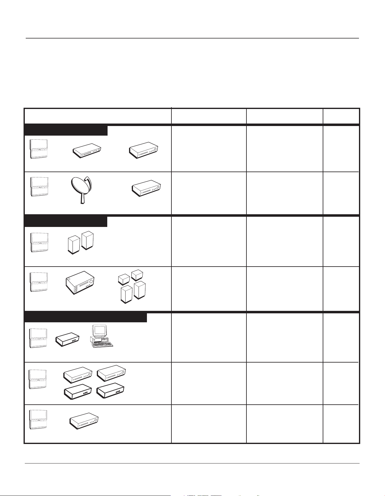
Choose Your Connection
There are several ways to connect your HDTV, depending on the components you want to connect and the quality of the
signal you want to achieve. Please use the following chart to determine which connection is best for you. Proceed to the
appropriate page and connect your TV. For more information about the relationship between the cables, jacks, and the
quality of the signal you see on your TV, go to page 18.
Components Cables Needed Connection Title Go to...
Video Connections
R
WE
O
P
+
VOL
—
VOL
CH
CH
NU
E
M
TV
POWER
+
L
O
V
—
VOL
TV
CH
CH
MENU
DVD
Satellite Receiver
Audio Connections
R
OWE
P
+
VOL
—
L
O
V
H
C
CH
U
EN
M
TV
TV
POWER
+
VOL
—
VOL
CH
CH
MENU
Speakers
A/V Receiver
VCR
VCR
Speakers
Coaxial
Audio/video
Component
Composite
G-LINK
Coaxial
Audio/video
Component
Composite
G-LINK
Speaker wire
Coaxial
Audio/video
Speaker wire
TV + DVD + VCR
TV + Satellite
Receiver + VCR
TV + Speakers Using
HDTV’s Center Channel
TV + A/V Receiver +
Speakers Using HDTV’s
Center Channel
page 10
page 11
page 14
pages 12,
13
Digital/Network Connections
Coaxial
POWER
+
OL
V
—
L
O
V
H
C
CH
TV
R
POWE
+
VOL
—
L
VO
CH
H
C
NU
E
M
MENU
Router
Computer
Cable Modem
Ethernet
Coaxial
1394 6-pin
TV
R
E
OW
P
+
VOL
—
VOL
1394 Components
H
C
H
C
U
EN
M
(no power)
Coaxial
Digital Visual
TV
HD Set-top Box
Interface (DVI)
Chapter 1 9
TV + Router +
Computer + Cable
Modem
TV + Digital VCR1 +
Digital DVD1 + Digital
Video Recorder +
Digital VCR2 + Digital
DVD2
TV + HD Set-top Box
page 15
page 16
page 17
Connections & Setup
Note for U.S. Customers: If you
R
POWE
+
VOL
—
L
VO
CH
H
C
U
EN
M
prefer, we can provide you with
the name of an Authorized
Service Representative who will
TV
visit your home for a fee to install
your electronic entertainment
system and to instruct you in its
operation. For details about this
service, call 1-888-206-3359. For
additional assistance while using
DVD
your RCA product, please visit
www.rcascenium.com/customer
support.
VCR
VCR
ANTENNA IN
ANTENNA OUT
VIDEO
AUDIO
L
OUT
VIDEO
IN
R
L
R
AUDIO
3A
3B
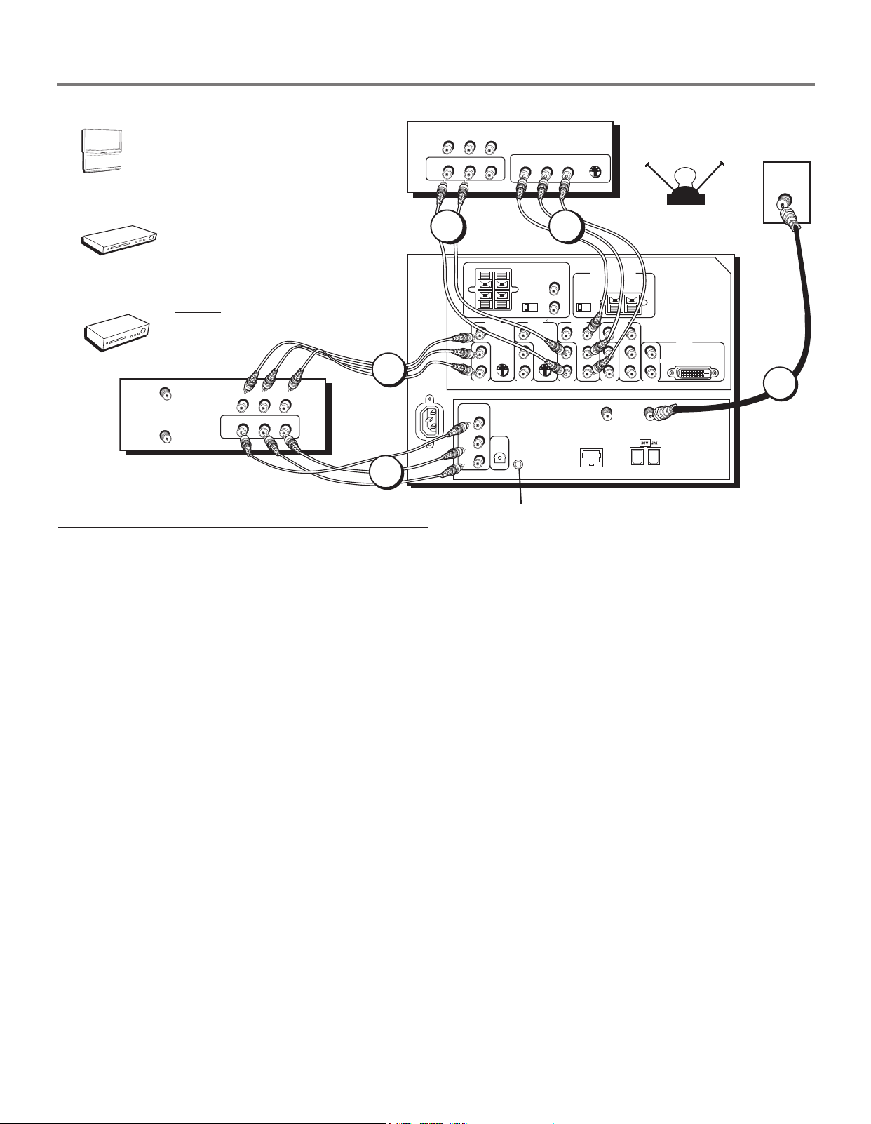
How to Connect: TV + VCR + DVD Player
AUDIO
VIDEO
L
R
IN
AUDIO
L
R
OUT
PR PB
VIDEO
DVD
S-VIDEO
Y
CABLE
OR
OFF-AIR ANTENNA
EXT
MONO
AUDIO
SPEAKER
SELECT
INPUT 2
G-LINK
INT W/
EXT
SURR
VIDEO
2
VIDEO
INPUT 5
DVI-HDTV
TV
1
AUDIO
OUTPUT
R
L
S-VIDEOS-VIDEO
V
MONO
L/
R
AUDIO
INPUT 3
INTERNAL
SPEAKER
SOURCE
TV EXT AMP
VIDEO
INPUT 3
ETHERNET
CENTER CHANNEL INPUT
EXTERNAL AMPLIFIER
MAXIMUM POWER RATING!
(60 WATTS into 8 OHMS)
VIDEO
INPUT 4
V
R
P
L/
B
MONO
P
Y
R
AUDIO
INPUT 4
ANTENNA B
INPUT
R
P
B
P
Y
ANTENNA A
L/
MONO
R
AUDIO
INPUT 5
INPUT
2
RIGHT FIXED/VARIABLE
EXTERNAL SPEAKERS
V
L/
MONO
R
AUDIO
INPUT 1
RECORD
OUTPUT
VIDEO
AUDIO
R
L
VIDEO
INPUT 1
DIGITAL
AUDIO
OUTPUT
LEFT
V
L/
R
INPUT 2
Connect G-LINK Cable (see page 23)
1. Connect your cable or off-air signal to ANTENNA A.
If you have cable and an off-air antenna, connect the cable signal to ANTENNA A INPUT (antenna A is the only source
for the GUIDE Plus+ system). Connect the off-air antenna to ANTENNA B INPUT. If you have only an off-air antenna,
connect it to ANTENNA A INPUT.
2. Connect your DVD Player to your TV.
Connect the DVD player’s component (Y PB PR) and audio outputs to INPUT 3 on the TV using component cables. If your
DVD player has composite audio/video and an S-Video output, use INPUTs 1 or 2 and use the S-VIDEO jack instead of
the VIDEO jack.
Notes: If you are using an S-Video cable (INPUT 1 or 2) or component video cables, you must also use audio cables. The
S-Video cable and component video cables only transfer video information.
If your DVD player has a component video output, we recommend you use the component video input on the TV instead of
the composite video or S-Video connection. Don’t forget to also connect audio cables when using the component video cables.
3. Connect your VCR to your TV.
A. Connect the VCR’s audio/video outputs to INPUT 1 (audio/video) on the TV using composite audio/video cables.
B. Connect the VCR’s audio/video inputs to RECORD OUTPUT on the TV. This enables recording of digital programs
(unless copy protected, using DVI HDTV or component video formats), as well as analog programs.
Viewing the Components
1. Turn on the TV and the component(s) you want to view.
2. Press the TV button on the remote control.
3. Press the INPUT button on the remote control to scroll through the Video Input Channels.
• The VCR can be viewed on the INPUT 1 channel.
• The DVD player can be viewed on the INPUT 3 channel.
Note: You can set up the TV to automatically tune to the correct Video Input Channel. This is called Auto Tuning. (See
Chapter 3 for more information.)
Go to page 23
10 Chapter 1
ER
OW
P
+
VOL
—
VOL
H
C
CH
U
EN
M
TV
Satellite
Receiver
VCR
VCR
ANTENNA IN
ANTENNA OUT
Connections & Setup
SATELLITE
EXT
MONO
L/
R
AUDIO
INPUT 2
SPEAKER
SELECT
G-LINK
INT W/
EXT
SURR
VIDEO
INPUT 2
S-VIDEOS-VIDEO
R
L
AUDIO
OUTPUT
RECEIVER
INTERNAL
SPEAKER
SOURCE
TV EXT AMP
VIDEO
INPUT 3
V
L/
MONO
R
AUDIO
INPUT 3
ETHERNET
CENTER CHANNEL INPUT
EXTERNAL AMPLIFIER
MAXIMUM POWER RATING!
(60 WATTS into 8 OHMS)
VIDEO
INPUT 4
V
P
R
P
B
MONO
L/
Y
R
AUDIO
INPUT 4
ANTENNA B
INPUT
P
R
B
P
Y
ANTENNA A
L/
MONO
R
AUDIO
INPUT 5
INPUT
OFF-AIR ANTENNA
VIDEO
INPUT 5
DVI-HDTV
CABLE
OR
TV
1
S-VIDEO
AUDI
VIDEO
L
R
3
RIGHT FIXED/VARIABLE
LEFT
EXTERNAL SPEAKERS
VIDEO
INPUT 1
V
V
MONO
L/
RECORD
OUTPUT
VIDEO
AUDIO
R
L
R
AUDIO
INPUT 1
DIGITAL
AUDIO
OUTPUT
2A
VIDEO
AUDIO
L
OUT
VIDEO
IN
R
L
R
AUDIO
2B
Connect G-LINK Cable (see page 23)
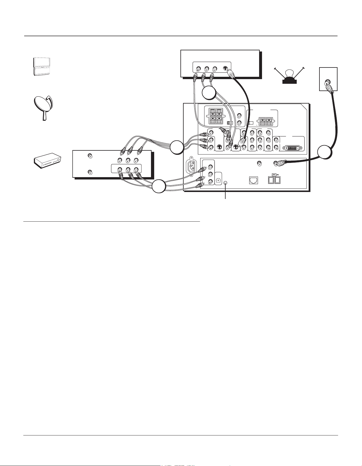
How to Connect: TV + Satellite Receiver + VCR
1. Connect your cable or off-air signal to ANTENNA A.
If you have cable and an off-air antenna, connect the cable signal to ANTENNA A INPUT (antenna A is the only source
for the GUIDE Plus+ system). Connect the off-air antenna to ANTENNA B INPUT. If you have only an off-air antenna,
connect it to ANTENNA A INPUT.
2. Connect your VCR to your TV.
A. Connect the VCR’s audio/video outputs to INPUT 1 (audio/video) on the TV using composite audio/video cables.
B. Connect the VCR’s audio/video inputs to RECORD OUTPUT on the TV. This enables recording of digital programs
(unless copy protected, using DVI HDTV or component video formats), as well as analog programs.
3. Connect your Satellite Receiver to your TV.
Connect the satellite receiver’s audio/video output jacks to the INPUT 2 AUDIO (R and L) and VIDEO jacks on the TV
using composite cables. If your satellite receiver has an S-Video output, you can make the video connection by using the
S-VIDEO jacks instead. If your satellite receiver has component outputs, then use INPUT 3 or 4.
Note: If you are using an S-Video cable or component video cables, you must also use audio cables. The S-Video cable
and component video cables only transfer video information.
Viewing the Components
1. Turn on the TV and the component(s) you want to view.
2. Press the TV button on the remote control.
3. Press the INPUT button on the remote control to scroll through the Video Input Channels.
• The VCR can be viewed on the INPUT 1 channel.
• The satellite receiver can be viewed on the INPUT 2 channel.
Note: You can set up the TV to automatically tune to the correct Video Input Channel. This is called Auto Tuning. (See
Chapter 3 for more information.)
Go to page 23
Chapter 1 11

Connections & Setup
Audio Connections
With the audio versatility of your HDTV, you can choose various connection options depending on the type and quality
of sound that you want. Choose one of the options or refer to the user’s manual of each component that you are
connecting to get the best results.
• Connect audio/video receiver (speakers connected to receiver) using the digital audio output jack to your TV (best sound).
• Connect audio/video receiver (speakers connected to receiver) to your TV (better sound).
• Connect speakers to your TV (good sound).
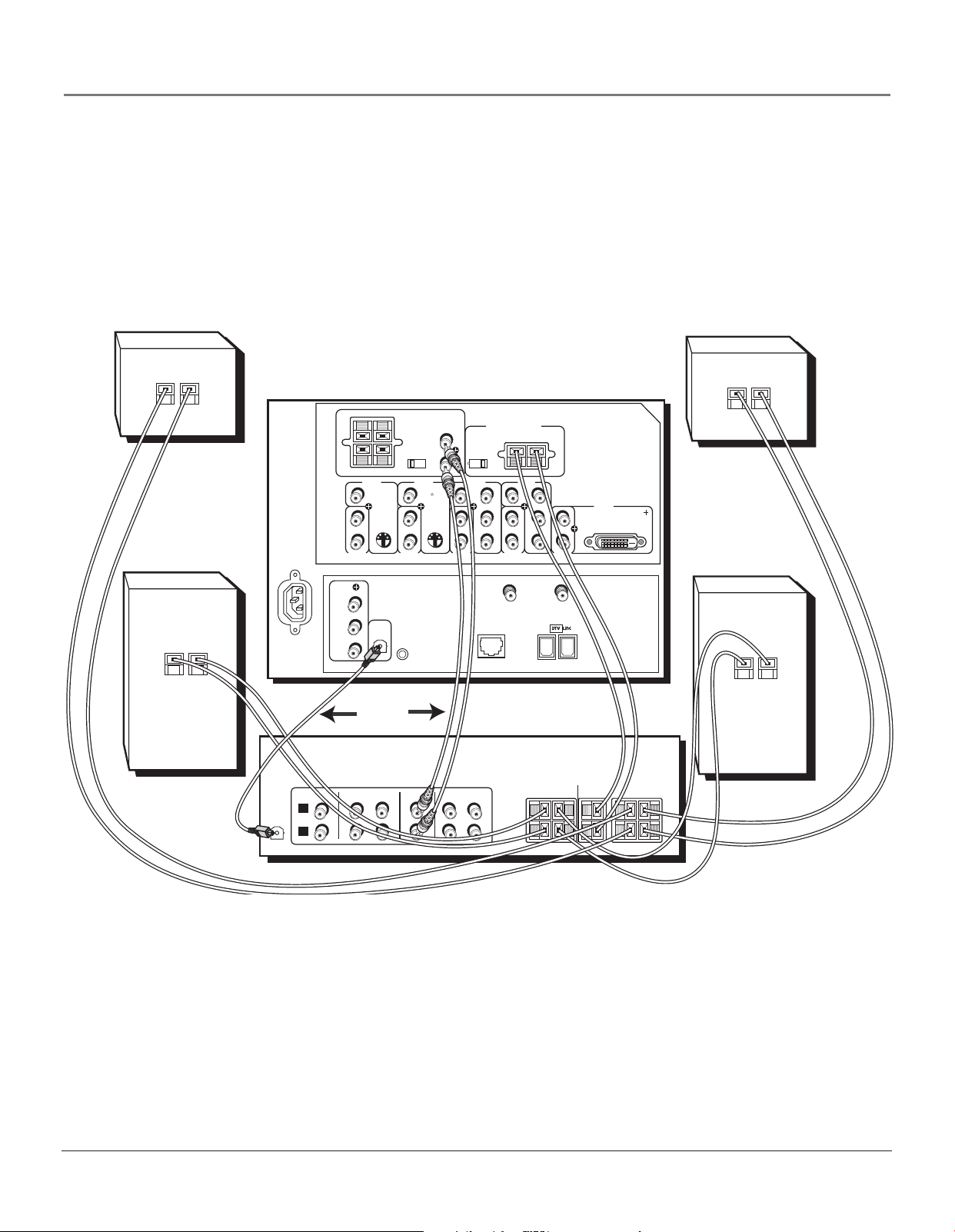
How to Connect: TV + Receiver with Dolby Digital + Speakers + Use TV as
Center Channel
If you own a receiver with Dolby Digital® or PCM (Pulse-Code Modulation) audio receiver that uses an optical cable-type
input, connect an optical cable for excellent audio quality (shown on opposite page).
1. Connect one end of the optical cable to the DIGITAL AUDIO OUT jack on your TV to the DIGITAL OPTICAL INPUT
Jack on your receiver/amplifier receiver.
• If your receiver can decode Dolby Digital and PCM, go to Audio menu, select Digital Audio Output, and
select AutoSelect (recommended) or PCM option.
• If your receiver can decode only PCM, go to Audio menu, select Digital Audio Output, and select PCM
option.
2. If you want to use your TV as the Center Channel, use speaker wire to connect the audio receiver’s CENTER
SPEAKER OUTPUT to the TV’s CENTER CHANNEL INPUT as shown on the opposite page.
• Switch INTERNAL SPEAKER SOURCE to EXT AMP.
3. Use speaker wire to connect the Audio/Video receiver to external front and rear speakers. Refer to your audio
receiver manual to complete speaker hookup to the receiver.
Caution: DO NOT connect your audio/video receiver’s outputs or center channel output to the red and black
EXTERNAL SPEAKERS OUTPUT on the TV. Damage to the TV may result.
OR
How to Connect: TV + A/V Receiver + Speakers + Use TV as Center Channel
1. Connect the FIXED/VARIABLE AUDIO OUTPUT from the TV to an A/V receiver using audio cables.
2. Be sure to go to the Fixed/Variable Out screen in the Audio menu and select whether you want the FIXED/
VARIABLE AUDIO OUTPUT jacks to send fixed volume audio or variable volume audio.
• Fixed Output provides fixed-level audio output from the TV. This audio output is ideal for connecting to an
A/V receiver that has its own volume control.
• Variable Output provides variable-level audio output. Volume levels are controlled by the volume controls on
the TV and TV remote control.
3. If you want to use your TV as the Center Channel, use speaker wire to connect the audio receiver’s CENTER
SPEAKER OUTPUT to the TV’s CENTER CHANNEL INPUT as shown on the opposite page.
• Switch INTERNAL SPEAKER SOURCE to EXT AMP.
4. Use speaker wire to connect the Audio/Video receiver to external front and rear speakers. Refer to your audio
receiver manual to complete speaker hookup to the receiver.
Caution: DO NOT connect your audio/video receiver’s outputs or center channel output to the red and black
EXTERNAL SPEAKERS OUTPUT on the TV. Damage to the TV may result.
*Manufactured under license from Dolby Laboratories. “Dolby” and the double-D symbol are trademarks of Dolby Laboratories.
12 Chapter 1
Connections & Setup
Back of Right Rear Speaker
+
–
+
–
LEFT
RIGHT FIXED/VARIABLE
EXTERNAL SPEAKERS
VIDEO
INPUT 1
V
L/
MONO
R
AUDIO
INPUT 2
Back of Left Front Speaker
DIGITAL
AUDIO
OUTPUT
RECORD
OUTPUT
VIDEO
AUDIO
R
L
V
MONO
L/
R
AUDIO
INPUT 1
OR
SPEAKER
SELECT
EXT
G-LINK
INT W/
EXT
SURR
VIDEO
INPUT 2
AUDIO
OUTPUT
R
L
S-VIDEOS-VIDEO
CENTER CHANNEL INPUT
INTERNAL
SPEAKER
SOURCE
TV EXT AMP
VIDEO
INPUT 3
V
L/
MONO
R
AUDIO
INPUT 3
ETHERNET
A/V AMPLIFIER
MAXIMUM AMPLIFIER POWER RATING
(60 WATTS into 8 OHMS)
VIDEO
INPUT 4
V
P
R
P
B
Y
ANTENNA B
MONO
L/
R
AUDIO
INPUT 4
INPUT
P
R
P
B
Y
ANTENNA A
L/
MONO
R
AUDIO
INPUT 5
INPUT
VIDEO
INPUT 5
DVI-HDTV
Back of Left Rear Speaker
+
–
TV
+
–
Back of Right Front Speaker
DIGITAL
AUDIO
INPUT
FRONT SPEAKERS
VCR
TAPE
CD
IN
IN
L
R
TV
IN
IN
OUT
OUT
RIGHT
LEFT
+
–
CENTER
SURROUND SPEAKERS
REAR
RIGHT
LEFT
Back of Left Front Speaker
+
–
Chapter 1 13
Connections & Setup
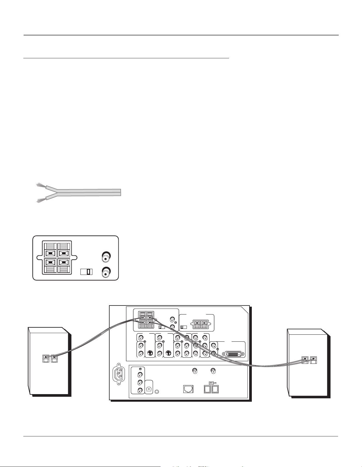
How to Connect: TV + Speakers Without A/V Receiver
You can connect two external speakers to the TV: one to the RIGHT terminal, and one to the LEFT terminal.
1. If necessary, remove the vinyl covering from the ends of the speaker wire and twist the wire core.
2. Open the lever on the speaker terminal.
3. Insert the wire core into the hole. Be sure to connect the (+) to (+) and (-) to (-).
4. Close the lever. Pull gently on the wire to see that it’s connected securely.
5. Set the SPEAKER SELECT switch:
• If you connect speakers and place the EXT/INT W/EXT SURR switch on the TV back panel in the INT W/
EXT SURR position, you get audio from the internal speakers as well as L minus R from both external
speakers. This connection gives you a matrix surround effect.
• If you connect speakers and place the switch in the EXT position, you get audio from the external
speakers only. The TV’s internal speakers are turned off.
6. Go to the Audio menu and Fixed/Variable Out screen and make sure
Variable Out - Speakers On is selected.
Notes:
When connecting the speaker wire, make sure you connect the positive
Speaker wire
(+) terminal on the TV to the positive (+) terminal on the speaker. One
side of the speaker wire is usually marked with a white stripe to help you
match the terminals correctly. If the (+) and (-) terminals are not matched
properly, the speakers will not be “in phase,” causing reduction in bass
frequencies.
RIGHT FIXED/VARIABLE
LEFT
SPEAKER
SELECT
EXT
EXTERNAL SPEAKERS
+
–
Back of Right Speaker
INT W/
EXT
SURR
AUDIO
OUTPUT
R
L
Do not allow the wire core to touch other wires or terminals. Damage to
components could result if the cores of two wires touch.
Arrange the speakers in your TV room to achieve maximum sound quality.
The external speaker rating is 8 ohms with 30 watts total power handling
capabilities.
LEFT
RIGHT FIXED/VARIABLE
EXTERNAL SPEAKERS
VIDEO
INPUT 1
AUDIO
V
L/
MONO
R
INPUT 2
DIGITAL
AUDIO
OUTPUT
RECORD
OUTPUT
VIDEO
AUDIO
R
L
V
L/
R
INPUT 1
MONO
AUDIO
SPEAKER
SELECT
EXT
G-LINK
INT W/
EXT
SURR
VIDEO
INPUT 2
AUDIO
OUTPUT
R
L
S-VIDEOS-VIDEO
V
L/
MONO
R
AUDIO
INPUT 3
TV EXT AMP
INPUT 3
CENTER CHANNEL INPUT
MAXIMUM AMPLIFIER POWER RATING
INTERNAL
(60 WATTS into 8 OHMS)
SPEAKER
SOURCE
VIDEO
V
P
R
P
B
Y
ANTENNA B
INPUT
ETHERNET
L/
MONO
R
AUDIO
INPUT 4
VIDEO
INPUT 4
P
R
P
B
Y
ANTENNA A
L/MONO
R
AUDIO
INPUT 5
INPUT
VIDEO
INPUT 5
DVI-HDTV
TV
Back of Left Speaker
+
–
14 Chapter 1
TV
Connections & Setup
Router Cable Modem/DSL Internet
Computer
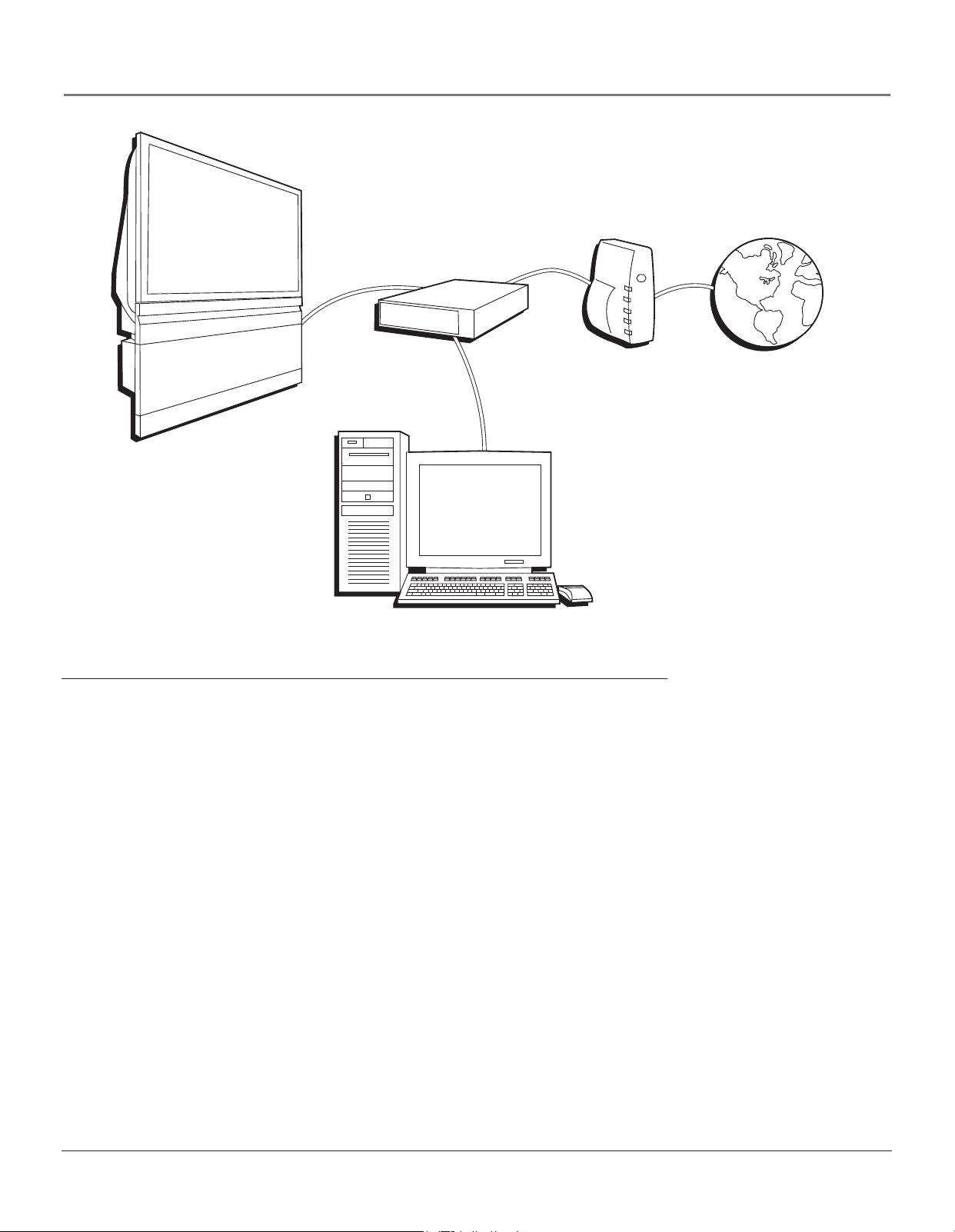
How to Connect: TV + Router via the HDTV’s ETHERNET Jack
The illustration above provides you with a general connection to the TV’s ETHERNET jack so you can maximize your
HDTV’s browser to surf the Internet. You don’t need to connect a computer to the router to surf the Internet. A computer is
only needed if you want to view photos or graphics on your TV that are stored on your computer. An Internet Service
Provider subscription is necessary to access the Internet.
You should know:
• Only use the Ethernet connection, if you are connecting a router to the TV’s ETHERNET jack.
•A router with DHCP capability is recommended.
• Only use this connection if you have purchased the keyboard designed for this HDTV (page 58 has ordering
information) because a keyboard is needed to effectively surf the Internet via your HDTV’s internal web browser.
•You’ll need to use the manuals that accompany your router and other Internet components for specific instructions.
A router enables you to network several components, such as a computer, cable modem, or DSL modem. You will need to
set up each component that is connected to the router. See the manuals that came with the router and the components you
are connecting for specific instructions.
To connect the router to the TV, use a CAT 5 cable (not provided) to connect the ETHERNET Input Jack on the back of your
HDTV to the ETHERNET Output Jack on the router.
The complexity of the setup required to make all of the components and the router work with your HDTV depends upon
your Internet Service Provider (ISP). Most ISPs will automatically fill in the information needed during setup, but if you are
asked for specific information while setting up the router and other components you will need to contact your ISP.
Chapter 1 15
Connections & Setup
TV
Digital Video Recorder Digital VCR
Digital VCR
TV
Fastest Slowest
Hub Connection
Other 1394 Component
Digital Video Recorder Digital VCR
Component-to-Component Connection
Digital VCR
Other 1394 Component
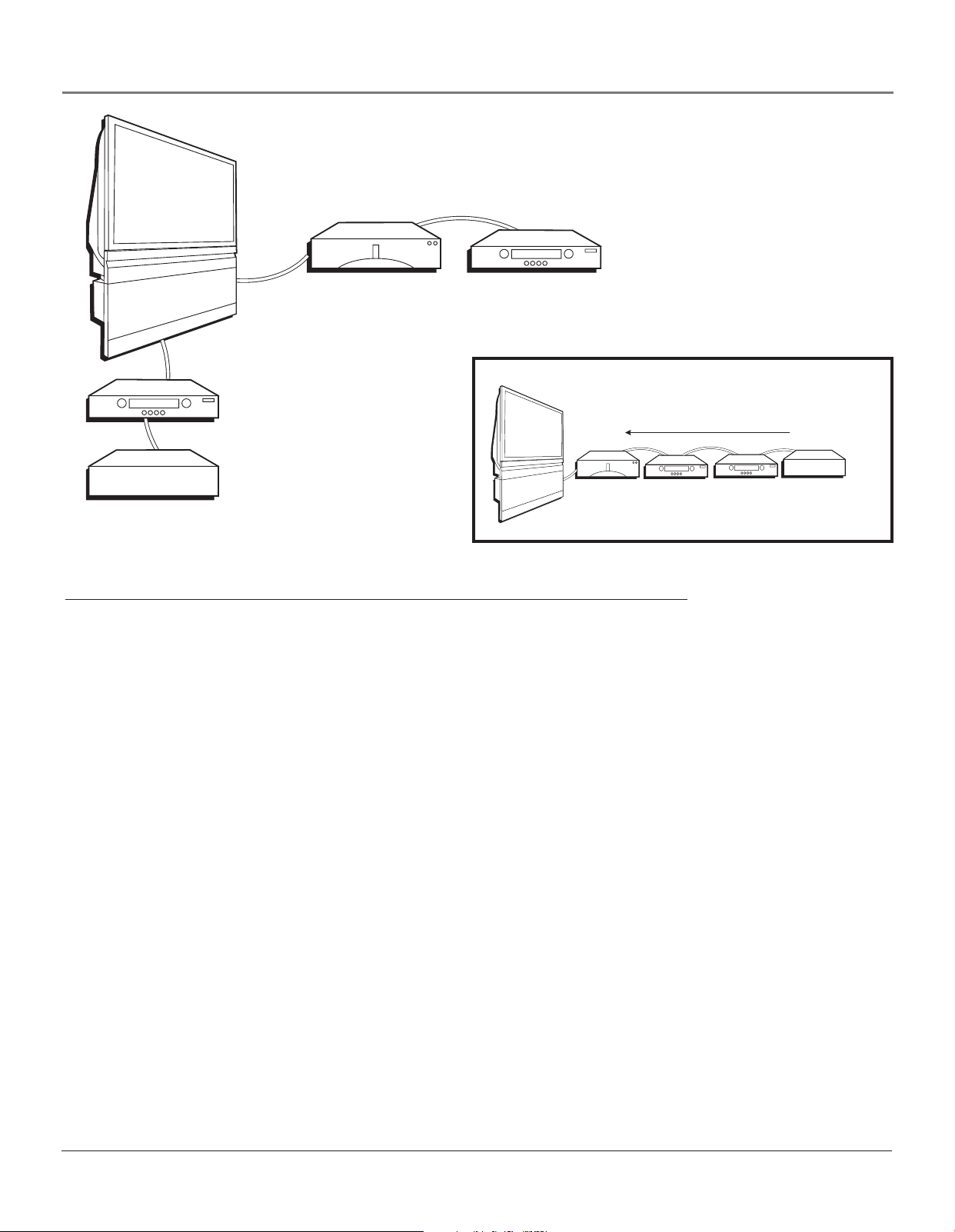
How to Connect: TV + DTVLink and/or IEEE-1394 Components
Two connection methods when connecting IEEE-1394 and DTVLink components are: component-to-component or hub. The
component-to-component method is each component connected in a chain-like fashion, one to the other with the first
component in the chain connected to the DTVLink jack on the TV. The hub method is basically the same but using both
1394 jacks with two chains of components connected. Your TV is a control center for the connected compatible
components, automatically recognizing each component and placing it in the Input list.
Note: If you’ve tuned to a 1394 input, you can control some basic transport functions on the component like RECORD,
STOP, FAST FORWARD, REVERSE, PAUSE, and PLAY when remote is in TV mode.
Three types of 1394 connectors are available on 1394 components; 4-pin connector (no power); 6-pin connector (with
power) and 6-pin connector (without power supplied). Your HDTV has a 6-pin connector (without power supplied). Both
the 4-pin and 6-pin connectors are capable of sending digital audio, digital video, and digital control signals back and forth
between components. In addition, the 6-pin connector is capable of sending low voltage electrical power. If you should
have some components with 4-pin connectors, 4-to-6 pin adapter cables are available from your local electronic stores.
You should know:
• Connect your 1394 components to either DTVLink (1394) jack.
• Only compatible 1394 components are to be connected to the DTVLink (1394) input/output jack.
• Do not loop the 1394 components back to the TV. That is, each 1394 connection chain should have only one
connection point to the TV, or the network might not work.
• Place the slower components at the end of the chain and the faster ones closest to the TV in the chain for faster
communication speed. See component’s manual for 1394 network speed.
• The TV can’t decode DV format of some camcorders, but it can decode/accept MPEG2 format from some camcorders.
Note: The TV sends audio/video through the 1394 jack (labeled DTVLink) only to a component that enforces video
copy protection.
16 Chapter 1
Connections & Setup
RIGHT FIXED/VARIABLE
RECORD
OUTPUT
VIDEO
AUDIO
R
L
LEFT
EXTERNAL SPEAKERS
VIDEO
INPUT 1
V
L/
MONO
R
AUDIO
INPUT 1
DIGITAL
AUDIO
OUTPUT
V
L/
MONO
R
AUDIO
INPUT 2
EXT
SPEAKER
SELECT
INPUT 2
G-LINK
AUDIO
OUTPUT
R
INT W/
EXT
SURR
L
VIDEO
S-VIDEOS-VIDEO
V
L/
MONO
R
AUDIO
INPUT 3
INTERNAL
SPEAKER
SOURCE
TV EXT AMP
VIDEO
INPUT 3
CENTER CHANNEL INPUT
V
P
R
P
B
Y
ANTENNA B
ETHERNET
EXTERNAL AMPLIFIER
MAXIMUM POWER RATING
(60 WATTS into 8 OHMS)
VIDEO
INPUT 4
L/
MONO
R
AUDIO
INPUT 4
INPUT
P
R
P
B
Y
ANTENNA A
L/
MONO
R
AUDIO
INPUT 5
INPUT
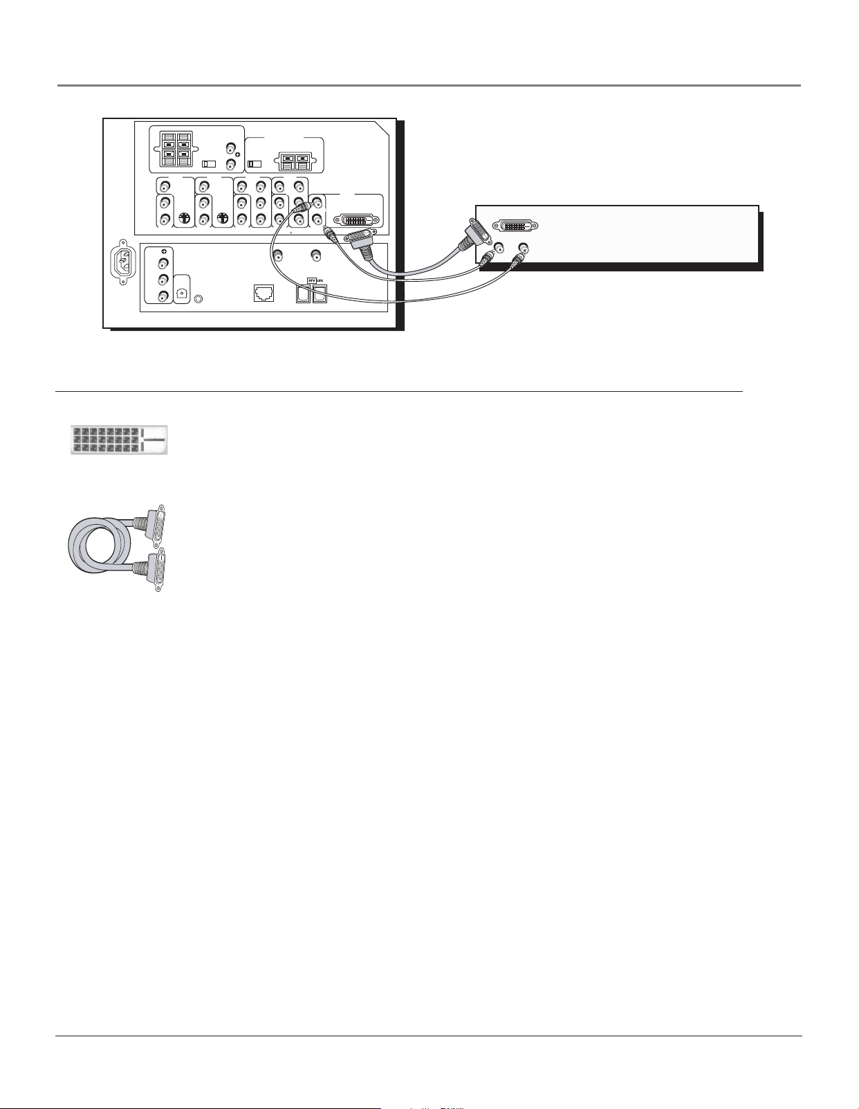
How to Connect: TV + Set-top Box Using DVI-HDTV (Digital Visual Interface)
Digital Visual Interface is a specification created by the Digital Display Working Group to support
analog and digital signals on a single interface. This uncompressed digital video interface is becoming
DVI-D Connector
more prevalent and is expected to become widely used for digital display components. The idea
behind the connector is that it could eventually replace the 15-pin VGA connector in consumer
electronic components.
VIDEO
INPUT 5
DVI-HDTV
TV
HD Set Top Box
L
R
DVI Cable
(not provided)
There are three different DVI formats: DVI-A for analog signals, DVI-D for digital signals, and
DVI-I for integrated signals (both analog and digital).
Your TV has a DVI-D format connector and supports some digital signals. The format is used for
direct digital connections between source video and provides a higher-quality image than analog. It
eliminates the analog conversion process and improves the connection.
You should know:
•A DVI cable has a 15 feet (5 meters) distance limitation.
• Audio information is carried separately; therefore, connect audio left and right cables.
Chapter 1 17
Connections & Setup
Digital Audio
Output Jack
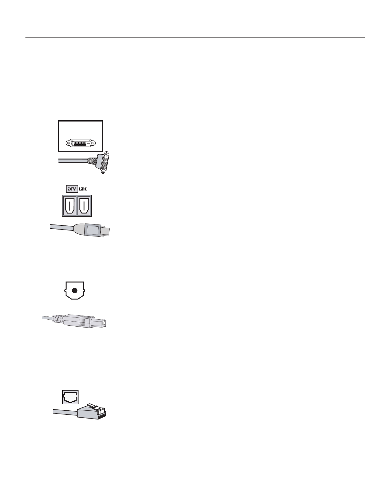
Explanation of Input Jacks and Cables
This section describes the jacks and cables you might use to make connections (cables may be ordered separately by using
the order form on page 85). There are several ways to connect components to your TV.
Different jacks and cables provide a different level of performance. It’s important to remember the different degrees of
picture improvement for comparison. The component jacks are considered an excellent improvement; S-Video and
composite jacks are considered very good, while connecting components with the antenna RF connection is good.
VIDEO
INPUT 5
DVI-HDTV
DVI-HDTV (Digital Visual Interface-High Definition Television) Connector
DVI-HDTV is an uncompressed, high-speed digital visual interface designed to
deliver digital video in its native format. It supports the overlay of highresolution graphics used by some program guides and interactive components.
Note: Remember to connect the left and right audio cables for Input 5
(DVI-HDTV) because the DVI-HDTV cable carries only the picture signal,
not the sound.
DTVLink® (Digital Television Link) Connectors
DTVLink uses a format better known to some as IEEE-1394 or FireWire®.
DTVLink is a compressed digital video input/output offering an IEEE 1394-type
connection that meets the CEA specifications. This connection is a high-speed
and inexpensive way of interconnecting 1394 compliant consumer electronic
components. If your 1394 component has the DTVLink logo on it, it should
work with this TV. You can use either or both connectors to link your
components but don’t connect the components in a loop.
Notes: Audio and video information is carried on a single wire.
The TV outputs audio/video through the 1394 jack (labeled DTVLink) only
to a component that enforces video copy protection.
Digital Audio Out Jack and Optical Cable
The optical cable is used to connect an audio receiver with Dolby Digital or
PCM (Pulse-Code Modulation) audio receiver to your TV. If you own a receiver
that uses an optical cable input, you can use an optical cable to connect the TV
to that receiver for the best sound quality.
Note: This TV’s optical digital output jack fully complies with the
international standard governing this type of jack (IEC958), and is
designed for connection to a Dolby Digital (AC-3® or PCM) receiver or
Dolby Digital (AC-3 or PCM) decoder. Older equipment, some of which is
not fully compliant with IEC958, may not be compatible with the Dolby
Digital bitstream. Such a connection using anything other than a Dolby
Digital (AC-3 or PCM) receiver or decoder could create a high noise level,
causing damage to headphones or speakers.
ETHERNET
Ethernet Jack and Cable
This jack is used to connect a router, cable modem or DSL (Digital Subscriber
Line) unit with a CAT 5 (ethernet) cable (not provided). It is recommended that
you only connect a router to this jack although you could connect a DSL/cable
modem directly.
DTVLink® Certification Logo is a U.S. registered mark of CEA.
FireWire® is a trademark of Apple Computer, Inc., registered in the U.S. and other countries.
18 Chapter 1
Y PB PR
Component Jacks
S-Video Jack
Connections & Setup
Component Video (Y•Pb•Pr) Jacks and Cables
The Y, Pb, Pr jacks allow you to connect a component, such as a DVD player.
This connection provides excellent picture quality because the video is
separated into three signals. To ensure maximum picture quality, use three
video-grade cables for the connection.
Note: Also, remember to connect the left and right audio cables because
the Y•Pb•Pr cables carry only the picture signal, not the sound.
S-Video Jacks and Cables
The S-Video (separate video) jacks provide better picture quality than the
regular video jacks because the color (chrominance, also called chroma) part of
the signal is separated from the black and white (luminance) part of the picture.
If a component you’re connecting to your TV (like a DVD player) has an
S-VIDEO jack and composite video, connect the component to the TV with an
S-Video cable (not provided) for a better quality picture.
Note: Remember to connect the left and right audio cables because the
S-Video cable carries only the picture signal, not the sound.
RF Jack
V L R
Audio/Video Jacks
Composite Audio/Video Jacks and Cables (RCA-type)
These jacks are used for most audio/video connections between components.
The audio/video jacks are often color coded (yellow for video, red for right
audio, and white for left audio). This is also called composite video.
Note: If your component has only one output for audio (mono), connect it
to the left (white L/Mono) audio jack on the TV and don’t connect the
right (red) audio part of the cable.
RF Jacks and Coaxial Cables (F-type)
RF jacks are primarily used for reception of off-air broadcasts and cable signals
(possibly older VCRs or cable boxes). The RF and coaxial jacks on the TV are
labeled ANTENNA A INPUT and ANTENNA B INPUT.
Chapter 1 19
Connections & Setup
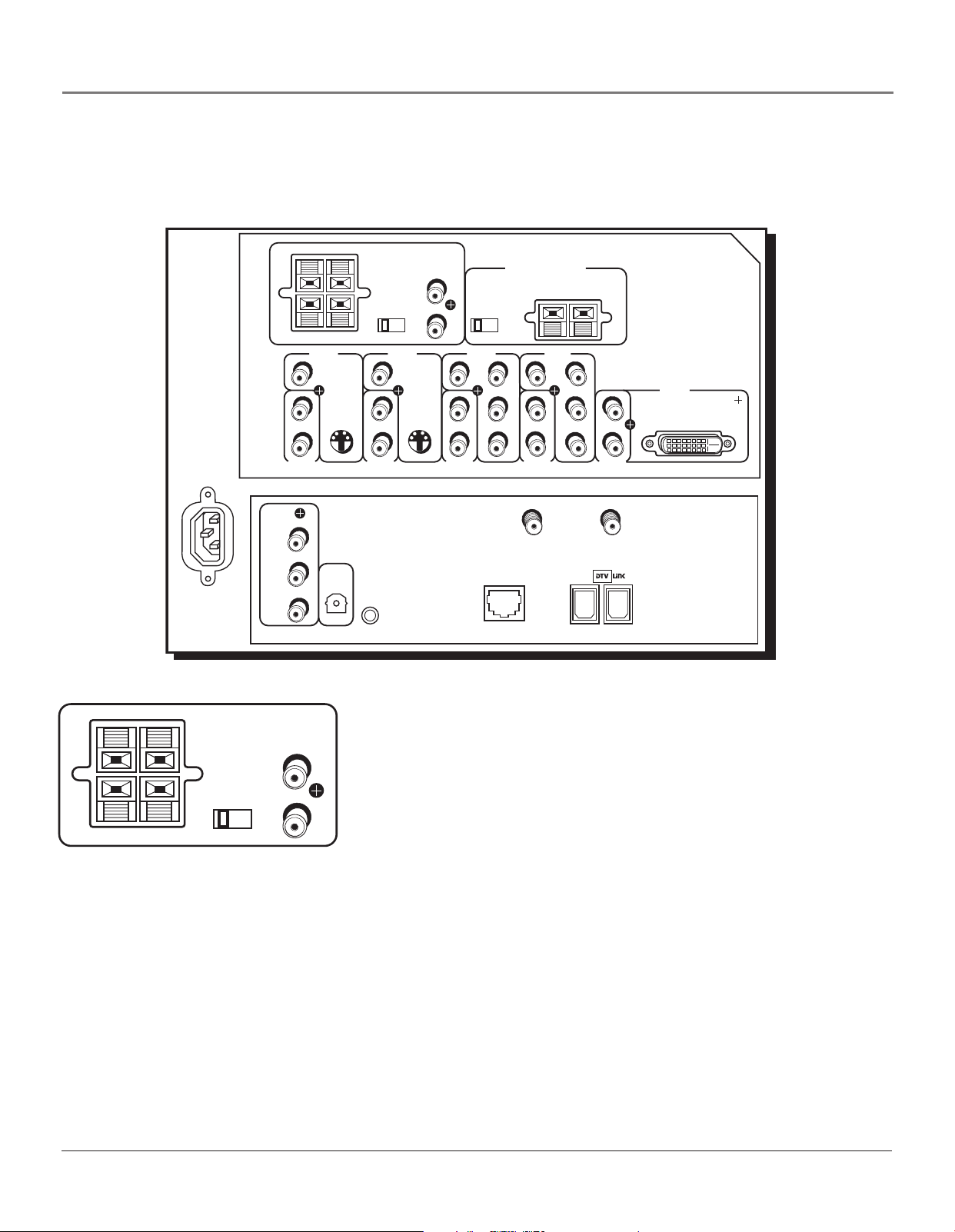
Back of the TV
The diagrams below illustrate jacks found on the back of the TV. When connecting cables, be sure to connect corresponding
outputs and inputs (video in to video out, right audio in to right audio out, etc.).
LEFT
RIGHT FIXED/VARIABLE
EXT
EXTERNAL SPEAKERS
VIDEO
INPUT 1
SPEAKER
SELECT
INT W/
EXT
SURR
VIDEO
INPUT 2
AUDIO
OUTPUT
R
L
INTERNAL
SPEAKER
SOURCE
TV EXT AMP
VIDEO
INPUT 3
CENTER CHANNEL INPUT
EXTERNAL AMPLIFIER
MAXIMUM POWER RATING
(60 WATTS into 8 OHMS)
VIDEO
INPUT 4
TV
V
L/
MONO
R
AUDIO
INPUT 1
RECORD
OUTPUT
VIDEO
AUDIO
R
L
RIGHT FIXED/VARIABLE
EXTERNAL SPEAKERS
LEFT
SPEAKER
SELECT
INT W/
EXT
EXT
SURR
AUDIO
OUTPUT
R
L
TV’s AUDIO OUTPUTS except
for RECORD OUTPUT audio
Caution: Connect external
speakers only to the TV’s
EXTERNAL SPEAKERS terminals.
DO NOT connect your audio/video
receiver to the red and black
EXTERNAL SPEAKERS terminals.
Damage to TV may occur.
DIGITAL
AUDIO
OUTPUT
V
L/
MONO
R
AUDIO
INPUT 2
G-LINK
V
S-VIDEOS-VIDEO
MONO
L/
R
AUDIO
INPUT 3
P
P
Y
ETHERNET
V
R
L/
B
MONO
R
AUDIO
INPUT 4
ANTENNA B
INPUT
R
P
L/
MONO
B
P
R
Y
AUDIO
INPUT 5
ANTENNA A
INPUT
VIDEO
INPUT 5
DVI-HDTV
AUDIO OUTPUTS
• RIGHT and LEFT EXTERNAL SPEAKER Terminals Used to connect
external speakers if you don’t have an audio amplifier or receiver. For use,
if you want better sound than the TV’s speakers. See page 14.
• SPEAKER SELECT - EXT. or INT W/EXT SURR Switch Lets you direct
where the output of the TV’s internal speakers goes. With the switch in the
EXT position, you hear the external speakers connected to the TV. In INT
W/EXT SURR position, you hear the TV’s internal speakers and external
speakers connected to the TV for a matrix surround sound effect.
Note: To turn the TV’s internal speakers on and off, press MENU on the
remote control and choose Audio. Then choose Fixed/Variable Out from
the menu and choose an option.
• FIXED/VARIABLE AUDIO OUTPUT L/R Provides fixed-level or variable-
level audio output from the television. Fixed/Variable is an option in the
Audio menu, details on page 66.
- Fixed controls the volume through the audio/video receiver.
-Variable controls the volume through TV.
20 Chapter 1
Connections & Setup
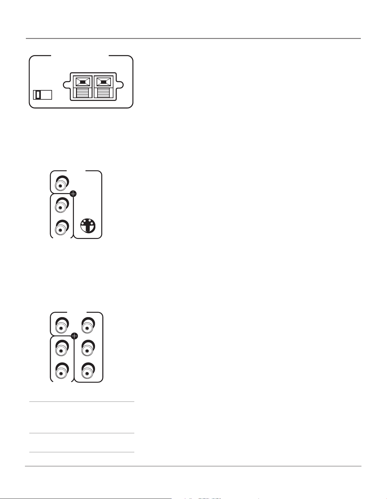
CENTER CHANNEL INPUT
INTERNAL
SPEAKER
SOURCE
TV EXT AMP
TV’s CENTER CHANNEL INPUTS
Caution: Do not connect the A/V
receiver’s CENTER CHANNEL
output to the TV’s EXTERNAL
SPEAKERS terminals. Damage to
TV may occur.
VIDEO
INPUT 1
V
L/
MONO
R
AUDIO
INPUT 1
S-VIDEO
CENTER SPEAKER INPUT
• INTERNAL SPEAKER SOURCE - TV / EXT AMP Switch
- TV Position Sound comes from TV’s internal speakers.
- EXT AMP Position Internal speakers are used for an external center
channel. When an external audio/video receiver’s center channel
output is connected to the TV’s center channel input, center channel
audio comes out of the TV’s internal speakers.
• CENTER CHANNEL TERMINALS Connect the audio/video receiver’s
center channel output to the TV’s center channel input. Switch the
INTERNAL SPEAKER SOURCE to EXT AMP position.
VIDEO/AUDIO INPUTS
VIDEO INPUT 1/AUDIO INPUT 1 Connect an NTSC (analog) component.
•V (VIDEO) provides composite video connection and connector is usually
yellow.
• L/MONO AUDIO provides left audio connection and connector is usually
white.
Note: If your component has only one output for audio (mono), connect
it to the left (white L/Mono) audio jack on the TV and don’t connect the
right audio part of the cable.
•R AUDIO provides right audio connection and connector is usually red.
VIDEO
INPUT 3
V
L/
MONO
R
AUDIO
INPUT 3
Tips
Inputs 3/4 can be used as either a component
video (Y PB PR ) input or a composite video (V)
input. The TV auto detects the connection with
Y PB PR having highest priority.
PIP cannot be displayed from component
(Y•Pb•Pr) inputs.
R
P
P
B
Y
• S-VIDEO lets you connect an S-Video cable for better video quality picture
to a component with S-Video capability, such as a VCR or DVD player.
When using S-Video, make sure to connect the two audio cables as well as
the S-Video connector.
VIDEO INPUT 2/AUDIO INPUT 2 Provides connection to a second NTSC
(analog) video component such as a VCR. The jacks are as described for INPUT 1.
VIDEO INPUT 3/AUDIO INPUT 3 Connect an optional component (Y PB PR)
video source, such as a DVD player or satellite receiver. Note that it is essential to
match the color coded connectors between a compatible component and the TV.
• AUDIO R/L/MONO The audio jacks provide stereo sound. When connected,
audio volume from the main front and rear speakers are variable.
•V (VIDEO) provides composite video connection and connector is usually yellow.
• Y PB PRUnlike a single video input, component video maintains the video
signal as three separate parts through these three jacks. To ensure
maximum picture quality, use three video-grade cables for the Y PB P
R
connections. Accepts 480i, 480p, 1080i signals. Has priority over V
connection.
VIDEO INPUT 4/AUDIO INPUT 4 Provides connection to a second optional
component video source, such as a DVD player or satellite receiver. The jacks
are the same as described in INPUT 3.
Chapter 1 21
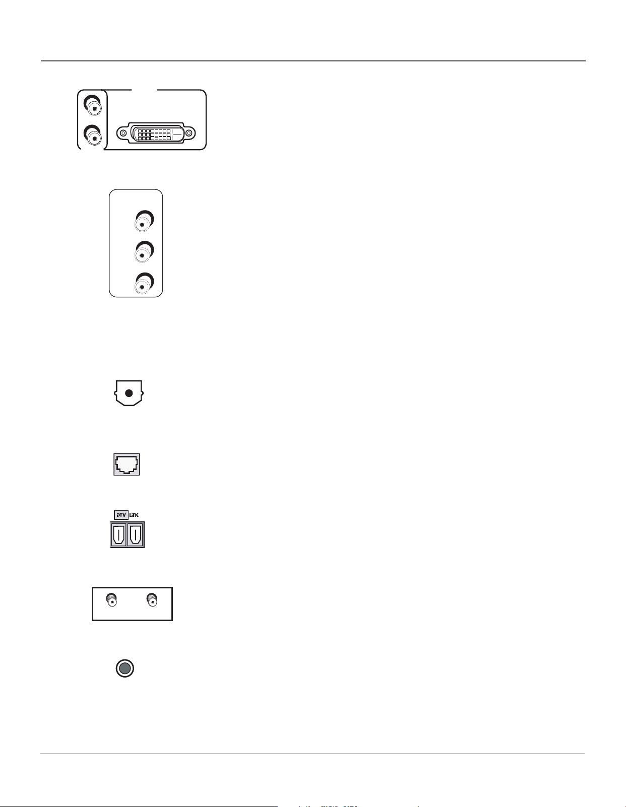
Connections & Setup
L/
MONO
R
AUDIO
INPUT 5
DVI-HDTV
RECORD
OUTPUT
VIDEO
AUDIO
R
L
VIDEO
INPUT 5
VIDEO INPUT 5/AUDIO INPUT 5 Provides DVI-HDTV and analog audio
connections.
• L/MONO AUDIO provides left audio connection and connector is usually
white.
•R AUDIO provides right audio connection and connector is usually red.
• DVI-HDTV provides a digital video connection from a video source to the TV.
RECORD OUTPUT Connect a VCR or DVD-recorder to record mainly digital (or
analog) programs from Antenna A or B and inputs (excluding DVI-HDTV and some
component video formats) while TV is turned on. You must leave TV on same
channel you are recording.
• VIDEO provides composite video connection and connector is usually yellow.
• AUDIO L provides left audio connection and connector is usually white.
• AUDIO R provides right audio connection and connector is usually red.
Notes: When recording from this output, remember to tune to the channel
you are recording.
If an unusual pattern appears when you connect your VCR input to the
RECORD OUTPUT, playing a tape or switching to the VCR’s tuner removes the
pattern.
Digital Audio
Output Jack
ETHERNET
ANTENNA B
INPUT
G-LINK
ANTENNA A
INPUT
DIGITAL AUDIO OUTPUT Use a digital optical cable (or SPDIF cable) to connect
your TV to a compatible Dolby Digital or PCM receiver or decoder. Dolby Digital
offers theatre-quality sound (six audio channels). Use the Digital Audio Out screen
in the Audio menu to select Auto Select or PCM as the output for this jack.
ETHERNET Connect a router, cable modem, or Digital Subscriber Line to the TV
using an Ethernet cable (CAT 5). Do not connect a telephone cable because of risk
of fire or shock. A green light on the jack means that an active network has been
detected. An orange light means the data is either being sent or received.
DTVLink Use either or both connectors to connect compatible DTVLink (IEEE-
1394) components but don’t loop the components together. When connecting
several components, use a hub or component-to component method. Be sure to
connect the fastest of the 1394 components closer to the connection point of the
TV and the slower components furthest away. Details on page 16.
ANTENNA A INPUT / ANTENNA B INPUTs Used to connect an off-air antenna
and/or cable TV signal to the TV. If you have both cable and air, connect cable to
ANTENNA A and off-air to ANTENNA B. If you have air only, connect it to
ANTENNA A. These inputs are also used to receive programming and connect
older components.
G-LINK Connect the G-LINK cable for VCR one touch recording and/or cable box
control with GUIDE Plus+ system.
22 Chapter 1
Connections & Setup
Why You Should Connect the G-LINK Cable
The G-LINK cable enables the GUIDE Plus+ system (the on-screen interactive program guide) to
work with your VCR and/or cable box.
Cable Box – If your TV is connected to a cable box, you must connect the G-LINK cable to receive
TV program listings for your area and to tune directly to a channel when the program guide is on
your TV screen.
VCR – If your TV is connected to a VCR and you don’t connect the G-LINK cable, one-touch VCR
recording and timed recordings won’t work. The other features of the guide will work properly.
How to Find the Remote Sensor
You have to place the G-LINK wands in front of the remote sensor on the VCR and/or cable box.
G-LINK cable
G-LINK wands
Some cable boxes and VCRs have the remote sensor labeled on the unit. If the remote sensor isn’t
labeled on your VCR and/or cable box, you need to use the remote control that came with the
VCR and/or cable box to locate the sensor.
1. Turn off the VCR and/or cable box.
2. Hold the remote control (not the one that came with your TV, but the one that came with the
cable box and/or VCR to which you’re attaching the G-LINK cable) so that it is touching the
front of the component.
3. Slowly move the remote control across the front of the component (VCR or cable box) while
you press the power button on and off. You must press and release the power button each
time you move the remote (holding down the button won’t work).
Tips
If you have both a VCR
and a cable box, it
doesn’t matter which
wand is connected to
which box.
If you don’t have both a
cable box and a VCR
connected to your TV,
just coil the cable of the
extra G-LINK wand with a
twist tie and leave it
behind the TV.
VCR
CABLE BOX
CHANNEL
03
4. When the component turns on, you’ve located the VCR’s or cable box’s remote sensor.
Placing the G-LINK Wands
Place the G-LINK wands in front of the remote sensor on your VCR and/or cable box
approximately one inch away from the remote sensor (see below).
LEFT
RIGHT FIXED/VARIABLE
AUDIO
OUTPUT
CENTER CHANNEL INPUT
MAXIMUM POWER RATING!
SPEAKER
INTERNAL
SELECT
SPEAKER
SOURCE
R
INT W/
EXT
SURR
EXT
TV EXT AMP
L
EXTERNAL SPEAKERS
VIDEO
VIDEO
VIDEO
INPUT 1
INPUT 2
INPUT 3
V
V
S-VIDEOS-VIDEO
L/
MONO
MONO
L/
R
R
AUDIO
AUDIO
INPUT 2
INPUT 3
ETHERNET
G-LINK
Connect to G-LINK jack
on the back of the TV
V
P
R
L/
P
B
Y
R
AUDIO
INPUT 4
ANTENNA A
INPUT
TV (back panel)
V
L/
MONO
R
AUDIO
INPUT 1
RECORD
OUTPUT
VIDEO
AUDIO
DIGITAL
AUDIO
OUTPUT
R
L
.
SENSOR
VCR
EXTERNAL AMPLIFIER
(60 WATTS into 8 OHMS)
VIDEO
INPUT 4
MONO
TV
P
R
VIDEO
INPUT 5
P
L/
MONO
B
DVI-HDTV
R
Y
AUDIO
INPUT 5
ANTENNA B
INPUT
CHANNEL
SENSOR
03
Chapter 1 23
Connections & Setup
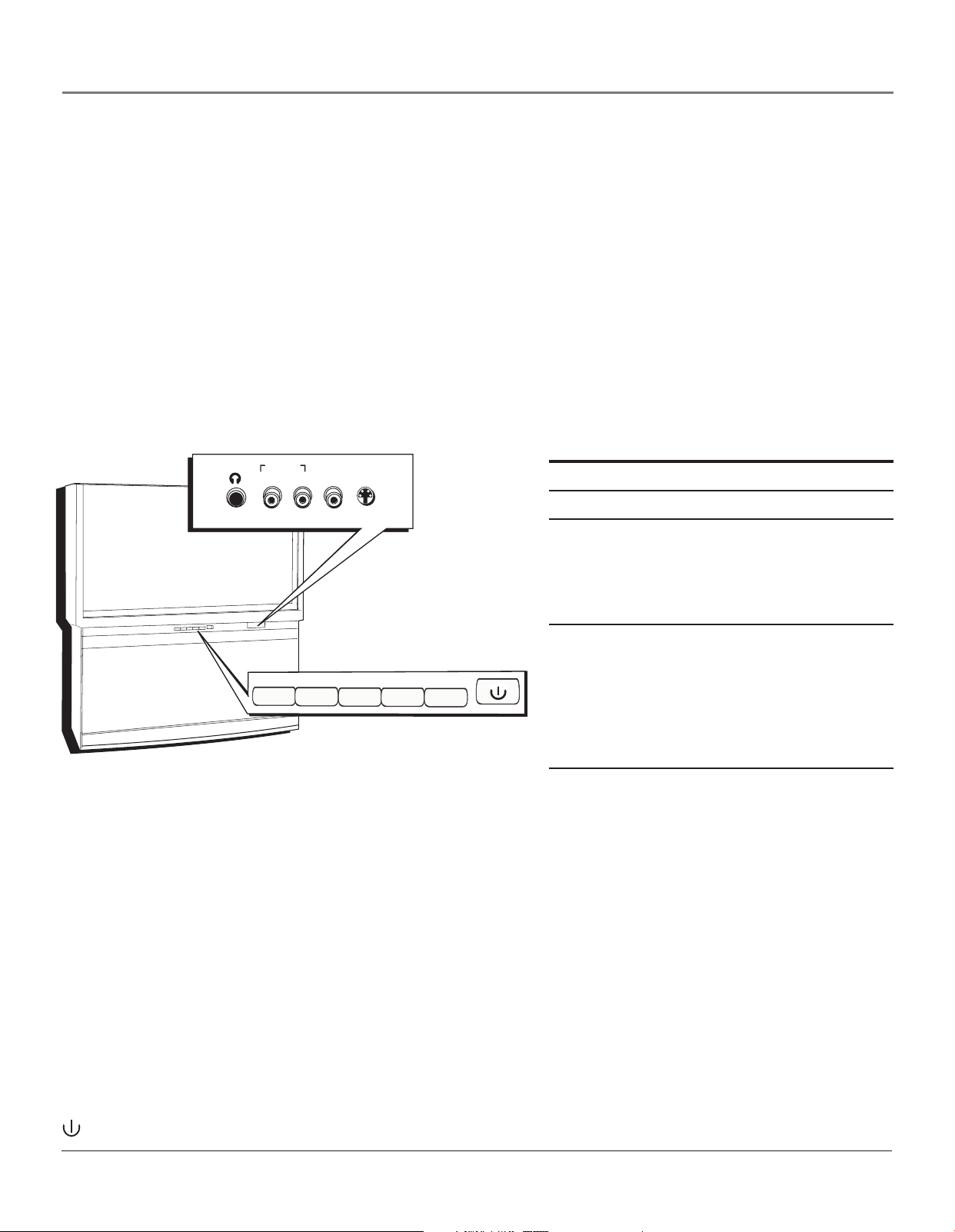
The Front of Your TV
Button Lighting
Your HDTV with DLP technology has a top-light feature above the buttons on the front of the TV. You can adjust the
brightness (including off) of the light through the TV’s menu system. Go to the Main Menu, highlight and select Preferences.
Go to the Button Lighting feature and make your adjustments by using the left and right arrow buttons on the remote.
Front Input Jacks
The TV has front input jacks for convenience in connecting a camcorder, digital camera, or video game: an S-VIDEO input,
one set of composite AUDIO/VIDEO inputs, and a headphone jack. Look for a hinged door and press to open the cover.
Please note the illustration below is just an example of how jacks might appear.
Notes: When you plug in headphones, the TV’s internal and external speakers, Fixed/Variable Audio Output, and
Digital Audio Output are automatically turned off.
When connecting a component that uses a monaural cable, such as some camcorders, use the Left (mono) input jack to
get sound from both speakers.
AUDIO IN VIDEO S-VIDE
L/MONO R IN I
O
N
Power Indicator Light Status
On TV is on
HEADPHONE
Off TV is off (standby mode)
Blinks If the power light blinks slowly,
you’ve tried to turn on the TV during
the lamp cooldown cycle. Wait
R
E
W
O
P
+
L
O
V
—
L
O
HV
C
H
C
U
N
E
M
approximately 30 seconds, and the TV
will turn on automatically.
Blinks and pauses Light blinks, pauses for about a
minute, and blinks again: the lamp is
MENU•O
C
H
VOL
VOL
K
C
H
trying to turn on (TV will turn on
when successful). If TV doesn’t turn
on and sequence continues, the lamp
needs to be replaced. See page 84 for
ordering information.
Notes: The front panel illustration shows a typical front panel layout. The exact look may be different from the one
on the front of your TV.
If you use the Front Button Block feature, the front panel no longer provides access to the menus. The Front Button
Block feature disables all front panel buttons but not the jacks. For more information, see Chapter 3.
Buttons on the Front of the TV
If you cannot locate your remote, you can use the front panel of your TV to operate many of the TV’s features.
MENU/OK Brings up the Main menu. When the menu system is displayed, pressing MENU/OK selects highlighted items.
CH
Scans up through the current channel list. In the menu system, it moves the highlight up in the menu and adjusts
menu controls.
CH
Scans down through the channel list. In the menu system, it moves the highlight down in the menu and adjusts
menu controls.
VOL
Decreases the volume. In the menu system, it moves the highlight left to items and adjusts menu controls.
VOL
Increases the volume. In the menu system, it moves the highlight right to items and adjusts menu controls.
(Power) Turns the TV on and off. The indicator light provides status of the TV and the DLP lamp. See chart above.
24 Chapter 1
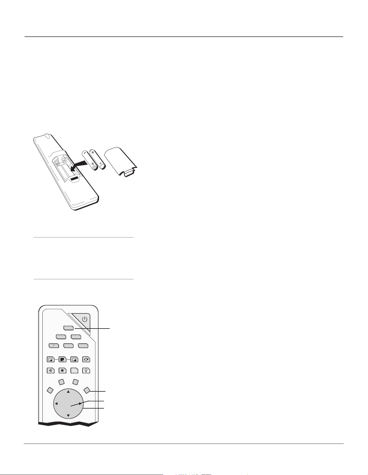
Connections & Setup
Plug in the TV
Plug the flat end of the cable into the power jack on the back of the TV. Then plug the other end
of the power cord into an appropriate wall outlet. Be sure to insert the plug completely. Do not
plug into an outlet controlled by a light switch.
Note: When you first plug your TV into an outlet, the Power indicator on the front panel
will light for approximately 15 seconds and then go off during the initialization of the TV.
The TV can only be turned on after the Power indicator goes off. This happens every time
power is reapplied to the TV.
Put Batteries in the Remote
• Remove the battery compartment cover from the back of the remote
by pushing down on the tab and lifting cover.
• Insert 2 fresh “AA” batteries. Make sure the polarities (+ and -) are
aligned correctly.
• Replace the cover.
Tip
When remote batteries are low, the component
button(s) corresponding to the mode you’re in
flashes when you press a button. Also, a
message might appear on the TV screen and
disappear within a few seconds. Press CLEAR to
remove.
ON-OFF
DVD VCR
SAT
CAB
SWAPSWAP
SOUNDSOUND
FREEZEFREEZE
FORMATFORMAT INFOINFO
CLEARCLEAR
TV
AUX AUDIO
CH. CTRLCH. CTRL
VCR PLUS+
VCR+
OK
SKIPSKIPPIPPIP
LIGHTLIGHT
MENUMENU
TV button
MENU button
OK button
Arrow buttons
Turn on the TV
Press TV on the remote, or press POWER on the TV’s front panel.
Note: Pressing the TV button turns on the TV and puts the remote
into TV mode. “TV mode” means that the buttons on the remote
control operate the TV’s functions.
Use the Remote Control to Complete
the Assisted Setup
The technical term is “Navigation” – how you move through the onscreen menus. The method is the same throughout the menu screens:
highlight your choice and select it.
To highlight a menu item, put the remote into TV mode by pressing the
TV button then MENU. Press the arrow buttons on the remote to highlight
one of the items listed in the menu. Use the up or down arrow button to
move up or down. Use the right or left arrow button to move right or left.
To select the item that you’ve highlighted, press OK.
Note: Highlighted means that the menu item stands out from
other menu items on the list (appears darker, brighter, or a
different color).
Chapter 1 25
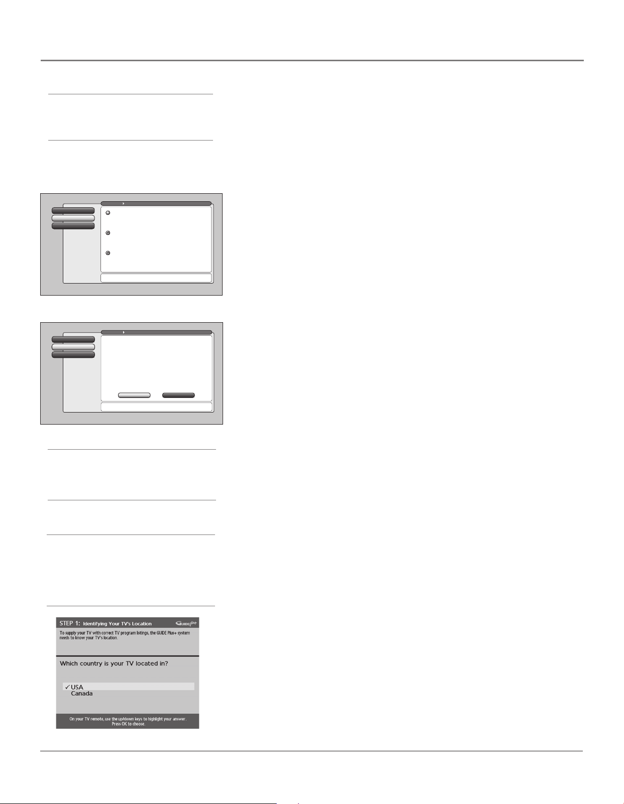
Connections & Setup
Tip
To access the setup menus, press MENU and
choose Assisted Setup.
Go Back
0
Closed CaptioningContinue Setup
1
Cancel Setup
2
Go Back
0
Antenna InfoContinue Setup
1
Cancel Setup
2
Main Menu Preferences
English
Highlight with the and arrows. Select with the OK button.
Note: Menu Language only affects the menus, not the GUIDE.
Español
Resalte con las flechas y . Seleccione con el botón OK.
Nota: Idioma de los Menús afecta sólo los menús, no la GUÍA.
Français
Mise en surbrillance avec et . Sélection avec OK.
Nota : Menu des langues pour les menus, non pour le GUIDE.
Press or to point to an option, then press OK to
select it. Press to return to the menu.
Main Menu Connections
Use Full Search the first time that your TV is setup to
search for channels on Antenna A and B. Full Search will also
automatically detect the proper Air or Cable setting.
A Full Channel Search requires several minutes to complete.
Thereafter, use Quick Search. It only searches the currentlytuned antenna, keeps the Air or Cable setting the same, and
is faster. Quick Search is useful when adjusting an
over-the-air antenna to receive the channels for your area.
Tip: If you have Cable and Air, connect Cable to Antenna A.
If you have only Air, connect it to Antenna A.
Status: Antenna A (Cable), Antenna B (Air).
Press OK to startt a Full Channel Search of both antennas
including automatic detection of Cable or Air antenna.
Quick SearchFull SearchFull Search
Complete the Assisted Setup
Your TV’s menu system allows you to adjust your TV’s features to be
configured to work properly. On-screen information helps you choose settings
to match your setup. The first time you turn on your TV, the Assisted Setup
screens appear automatically. Select Begin Setup to start or select Cancel Setup
to exit.
Set the Menu Language
1. Use arrow buttons to highlight your preferred language for the
menu system.
2. Press OK to select that language.
3. Select Continue Setup.
Complete Channel Search
Even though this initial channel search can take several minutes, it is important
to complete in order for your TV to display channels and programming.
1. Highlight Full Search with arrow button and press OK to tell the TV to
begin searching for channels. A progress report appears on the screen.
2. When search is complete, press OK.
Tip
Channel Search takes several minutes because
the TV is searching for all possible analog and
digital channels. You may want to leave and
come back later.
Tip
If you move to a new ZIP or postal code, or if
any of your information changes and you need
to access the setup screens from the TV’s main
menu— press MENU, choose GUIDE Plus+
Menu, and choose GUIDE Plus+ Setup, then
choose “No, repeat setup process.”
3. Select Continue Setup.
Notes: If you skip Channel Search now, you can access it later through
the Connections menu. See Chapter 4 for more details.
If cable box is connected to ANTENNA A, Channel Search cannot work.
The GUIDE Plus+ System Setup
Important Notes: If you have a VCR and/or cable box connected to the
TV, you need to connect the G-LINK cable to use the GUIDE Plus+ system.
If you didn’t connect the G-LINK cable, go to page 23. Disregard the
screen that tells you to refer to the Quick Setup sheet—all of the
instructions are included in this User’s Guide.
The TV must be off to download information. Leave your TV off
overnight, for at least 10 hours to receive the initial download for your
area.
The GUIDE Plus+ system is a no-fee, on-screen interactive program guide that
lists what shows are on TV in your area. In order to receive program listings,
you need to complete the following steps after you read the introductory
screens.
Step 1: Identifying Your TV’s Location
1. If your country is highlighted, press OK on the remote control.
If your country isn’t highlighted, press the up or down arrow button on the
remote control to highlight your country and press OK.
26 Chapter 1
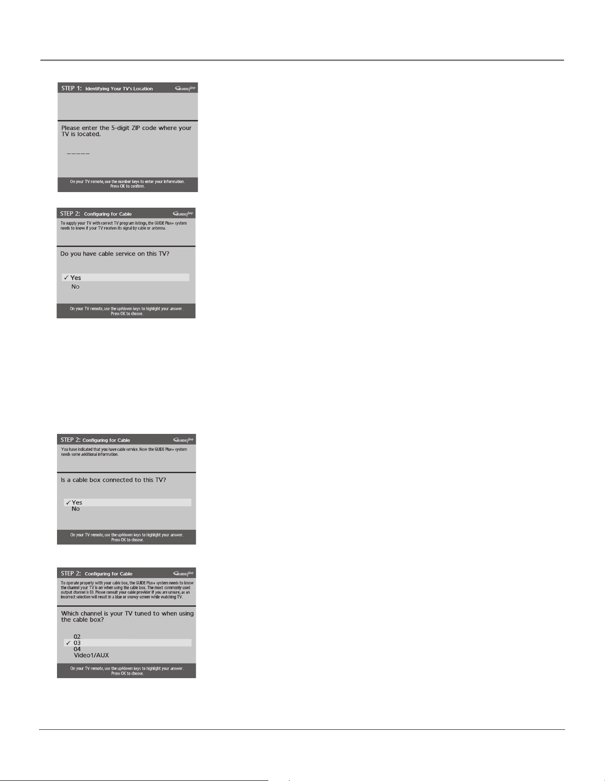
Connections & Setup
2. Use the number buttons and/or the arrows on your remote to enter your
zip code or postal code. Press OK when you’re finished.
Note: If your postal code contains letters, press the up and down arrow
buttons on your remote to enter letters, and press the right arrow button
to go to the next space. The left arrow button also moves the highlight
to the left.
Step 2: Configuring for Cable
The next series of screens asks you about your cable setup. To supply your TV
with the correct TV program listings, the GUIDE Plus+ system needs to know if
your TV is connected to a cable TV connection.
Notes: If you’re using a cable box, leave it on so you can receive program
information.
If you have two off-air antennas connected (one to ANTENNA A and one
to ANTENNA B) and you aren’t getting the guide listings, try swapping
the antennas.
You cannot tune to digital channels from the GUIDE Plus+ system if you
have cable service or a cable box connected unless an off-air antenna is
connected to Antenna B.
1. If your TV is connected to cable, highlight Yes and press OK.
If your TV isn’t connected to cable, highlight No and press OK. (STEP 3:
Configuring for a VCR appears--go to page 28.)
2. If you have a cable box connected to this TV, highlight Yes and press OK
Notes: The next series of screens is very important because the GUIDE
Plus+ system must find the correct cable box information in order to
receive the correct TV program listings.
If you don’t have a cable box connected to this TV, highlight No and
press OK (STEP 3: Configuring for a VCR appears--go to page 28).
3. Highlight the channel on ANTENNA A where you have to tune your TV to
see cable box programming, and press OK (a screen appears reminding
you to connect your G-LINK cable to your TV and cable box).
Notes: If not using INPUT1 (VIDEO1/AUX), you must connect to ANTENNA
A not B.
Channel 03 is the most common.
Choose Video1/AUX if your cable box is connected to your TV with audio/
video cables instead of a coaxial cable. Go to page 8 for pictures of these
cables. If you choose Video 1/Aux, then connect the cable box to the
INPUT 1 on back of TV.
Chapter 1 27
 Loading...