

Page 1

Changing Entertainment. Again.
Find Inside:
• The DLP Experience ... page 1
• Connections ................. page 7
• Remote .......................... page 27
• Features ........................ page 37
HDTV User’s Guide
• Menus ............................ page 47
• FAQs ...............................page 62
• Troubleshooting .........page 63
rca.com/television
Page 2
Important Information
WARNING
To reduce the risk of fi re
or electric shock, do not
expose this product to rain or
moisture. The apparatus shall
not be exposed to dripping or
splashing and no objects fi lled
with liquids, such as vases, shall
be placed on the apparatus.
Refer to the identifi cation/rating label located on the back panel of your product for its proper operating voltage.
FCC Regulations state that unauthorized changes or modifi cations to this equipment may void the user’s authority
to operate it.
Cable TV Installer: This reminder is provided to call your attention to Article 820-40 of the National Electrical
Code (Section 54 of the Canadian Electrical Code, Part 1) which provides guidelines for proper grounding and, in
particular, specifi es that the cable ground shall be connected to the grounding system of the building as close to
the point of cable entry as practical.
CAUTION
RISK OF ELECTRIC SHOCK
DO NOT OPEN
This symbol indicates
"dangerous voltage" inside
the product that presents
a risk of electric shock or
personal injury.
This symbol indicates that the lamp in the HDTV contains mercury.
Special disposal of the lamp for environmental reasons may be
required under the laws applicable to your jurisdiction. For disposal
or recycling information, please contact your local authorities or the
Electronic Industries Alliance: www.eiae.org, or call 1-800-338-0376
for more details.
Caution: To reduce the risk of electric shock, do
not remove cover (or back). With the exception of
the lamp, no user serviceable parts inside. Refer
servicing to qualifi ed service personnel.
This symbol indicates
important instructions
accompanying the product.
Important: This television is a table model and is designed to sit on a fi rm, fl at, surface. Don't place the TV on
soft carpeting or similar surface because the ventilation slots on the bottom of the unit will be blocked resulting in
reduced lifetime from overheating. To assure adequate ventilation for this product, maintain a spacing of 4 inches
from the top and sides of the TV receiver and 2 inches from the rear of the TV receiver and other surfaces.
Also, make sure the stand, cabinet, or base you use is of adequate size and strength to prevent the TV from being
accidentally tipped over, pushed off, or pulled off. This could cause personal injury and/or damage the TV. Refer to
the Important Safety Instructions packed separately.
Product Registration
Please fi ll out the product registration card (packed separately) and return it immediately. For U.S. customers: Your
RCA Consumer Electronics product may also be registered at www.rca.com/television. Returning the card allows us
to contact you if needed.
Product Information
Keep your sales receipt to obtain warranty parts and service and for proof of purchase. Attach it here and record
the serial and model numbers in case you need them. These numbers are located on the product.
Model No. ______________________________________________________________________________________________
Serial No ._______________________________________________________________________________________________
Purchase Date: __________________________________________________________________________________________
Dealer/Address/Phone: ___________________________________________________________________________________
Page 3

Introduction
Thank you for choosing RCA
Congratulations on purchasing this RCA High Defi nition Television (HDTV) featuring Texas Instruments
Digital Light Processing® technology–a true viewing experience. Your purchase decision represents an
investment in a new generation of technology–DLP and HDTV. Even though this is a technologically
advanced HDTV, it is the most user-friendly of its kind–with comprehensive on-screen instructions that
guide you through all of the TV’s features.
This introduction has three parts that describe why an RCA HDTV featuring DLP technology is an
excellent choice:
Part 1: DLP technology–brilliance in color and design
Part 2: Why RCA DLP HDTV is better
Part 3: Other Key Features of owning an RCA HDTV
Part 1: DLP technology–brilliance in color and design
RCA brings you pictures with DLP system–a brilliantly choreographed, engineering marvel that combines
microscopic mirrors, light, and color to bring you the best and brightest pictures possible.
Common Field Lens
DMD
Illumination Relay Optics
Integrating Light Pipe
EXAMPLE: Service Model Number sticker
with lamp type listed.
Model No.____________________________________
Lamp Type___________________________________
Projection Optics
Screen
Color Wheel
Lamp
Service Model Number Numéro de Modéle-Service
HDLP50XXXXXX
000000000 X
SERIAL SERIE LAMP
How DLP Technology Works
In general, DLP technology combines microscopic mirrors, a specially
designed semiconductor, and a color wheel to adjust light to display the
most brilliant, accurate images! Your DLP HDTV doesn’t use Cathode
Ray Tubes (CRTs), which means you don’t have to worry about screen
burn (fi xed video images burning onto the screen permanently) or
convergence (realigning the CRTs). The diagram on the left illustrates the
complex system.
Thin and Light
The effi ciency of DLP technology enabled our design team to create a
high-performance HDTV that is about 16 inches thin and weighs less
than 100 pounds.
Lamp Replacement
DLP technology uses a special lamp. Eventually, you’ll need to replace this
lamp, which you can do yourself by following the instructions that come
packed with the new lamp. To order the correct lamp, you’ll need to know
your TV’s model number, serial number, and lamp type–this information
is listed on the Service Model Number sticker (example of the sticker is
shown on the left). Face the back of the TV. The sticker is located on the
left side of the TV. For future reference, write down the information in the
space provided at the left.
Date_________________________________________
DLP® is a trademark of Texas Instruments
1
Page 4

Introduction
Part 2: Why RCA HDTV is better
DLP technology is just part of the story. You have chosen to embark on the next generation of TV viewing–HDTV. There are many
technological advancements that make HDTV better than analog TV, but there are basically three things about HDTV that bring you a
superior viewing experience: (1) resolution, (2) aspect ratio, and (3) digital signal and sound.
Resolution (it’s math...that works for you)
The crisp, lifelike picture that people rave about when experiencing true HDTV is due to the resolution this technology provides. The
resolution is measured by calculating the number of pixels. A pixel (which stands for picture element) is a small dot. The picture you see on
your TV is composed of these dots.
A regular, analog television only has a resolution of about 200,000 pixels (480 vertical pixels x 440 horizontal pixels = 211,200 pixels). The
HDTV format is capable of more than 2 million pixels (1,920 x 1,080 = 2,073,600).
More pixels equal more detail. In summary, HDTV is capable of resolution that is up to almost 10 times the resolution of the picture on a
regular, analog TV!
Feature Analog (NTSC) HD Digital (ATSC)
Total Scan Lines 525 1125
Effective Scan Lines 480 1080
Aspect Ratio 4 x 3 (Standard) 16 x 9 (Widescreen)
Max Resolution 720 x 480 1920 x 1080
Sound 2-ch Stereo 5.1 ch Surround
16 x 9 Aspect Ratio
4 x 3 Aspect Ratio
Aspect Ratio
Aspect ratio is simply the width and height of the picture. Regular TVs use a 4 x 3
aspect ratio, which means the picture is a little wider than it is tall (a screen that is 20
inches wide is about 15 inches tall).
When the standards were being developed for television broadcasting in 1941 by the
NTSC (the National Television Standards Committee), it made sense to adopt the
4 x 3 aspect ratio the fi lm industry was using at that time.
As TVs dropped in price and people prospered in the 1950s, the movie industry had
to fi nd a way to get people out of their living rooms and back to the movie theatres.
That’s when they created the 16 x 9 aspect ratio (also called widescreen format). When
the standards for HDTV were being developed by the ATSC (Advanced Television
Standards Committee), the 16 x 9 aspect ratio was chosen as the format for HDTV.
This widescreen format makes sense because it’s much closer to the way we see. Our
fi eld of vision is actually much wider than tall because of our peripheral vision. Not
only is it closer to the way we see, but the pictures are crisper and cleaner with more
detail in the close-up and panoramic views.
2
Page 5
Introduction
Digital Signal and Sound
The analog television broadcast system that has been used in the United States for the past 50 years transmits signals as electronic waves.
These waves can suffer degradation as the signal travels to your home. Additionally, the analog waves are susceptible to interference from
planes passing overhead, weather, and household appliances.
Digital signals, in contrast to analog signals, can be reproduced precisely because the images are transmitted and received using the
computer language of 1s and 0s. Such precision yields a signal that is capable of displaying studio-quality picture and Dolby Digital 5.1
channel sound.
Part 3: Other Key Features of owning an RCA HDTV
There are other HDTV’s on the market– even some that use DLP technology. But your RCA HDTV has been designed with features that
will enhance your TV viewing experience, and features that provide fl exibility to build on the digital revolution that is taking place. A
summary of your TV’s most unique features follows. Go to Chapter 3 for more details on these and additional features.
Integrated HDTV Tuner with Digital Cable Ready QAM
RCA was the fi rst to offer an integrated tuner with its HDTVs, which means there is no need for another box to receive digital
programming. Now, we’ve gone one better–your HDTV’s tuner is digital cable ready, which means there is no need for a cable box to view
unscrambled digital cable programming. The CableCARD™ slot on your HDTV allows you to use a digital cable card to access digital
cable. The tuner is able to decode all formats of digital television broadcasts, and it can interpret unscrambled digital cable signals because it
includes QAM (Quadrature Amplitude Modulation).
Note: A digital cable card may be necessary to view scrambled (encrypted) channels. Contact your cable provider for more information.
Go to page 10 for more information.
TruScan Digital Reality
The intelligent signal processing of TruScan Digital Reality recognizes incoming video signals and progressively converts them to achieve
optimum digital picture performance. It also recognizes when original fi lm sources have been modifi ed and can automatically convert the
analog frame rate back to its original format to bring out the detail–a process commonly referred to as reverse 3:2 pulldown.
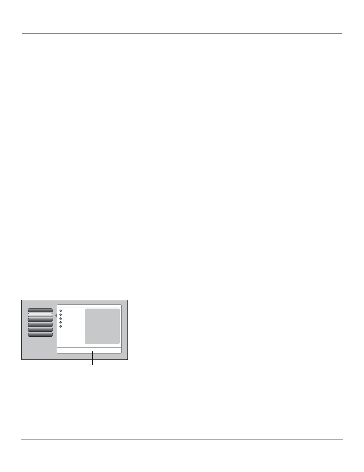
Go Back
0
Picture Preset Mode
1
Picture Settings
2
Screen Format
3
Advanced Picture
4
Screen Adjust
5
4Picture Menu
Main Menu
Vibrant (Day)
Natural
Cinematic (Night)
Sports
Personal
A change in this screen is applied to Input 3.
Press 5 or 6 to point to an option, then press OK to select it.
Press 3 to return to the menu.
Contrast 65%
Color 70%
Tint 55%
Brightness 60%
Sharpness 55%
Auto Flesh Tone On
Color Temperature Cool
Video Noise Filter Frame Comb
Green Enhance On
Detail Enhance On
Contrast Enhance On
Help text
User-friendly Features Help You Personalize Your TV
• You can customize your TV to fi t your viewing taste and match the lighting where
you watch TV by using Personal Presets and/or the picture preset settings: Vibrant
(Day), Natural, Cinematic (Night), and Sports. You can adjust each input jack to a
different setting and the TV will automatically adjust the picture when you change
inputs.
• Help Text: The on-screen help text describes your TV’s features and explains how to
use them.
CableCARD™ is a trademark of Cable Television Laboratories, Inc.
3
Page 6

This page left intentionally blank.
Page 7

Table of Contents
Introduction .......................................................................................................................1
Chapter 1: Connections & Setup
Things to Consider Before You Connect .........................................................................8
Protect Against Power Surges ....................................................................................8
Protect Components from Overheating ....................................................................8
Position Cables Properly to Avoid Audio Interference .............................................8
Use Indirect Light ........................................................................................................8
FCC Statement ...........................................................................................................8
Get the Picture ..................................................................................................................9
Getting Cable Channels ..............................................................................................9
Getting Digital Channels ............................................................................................9
Using the CableCARD Slot ........................................................................................10
Setting Up Digital Cable Television Service .............................................................10
Choose Your Connection ................................................................................................11
Y Pb Pr (Component Video) Connection .................................................................12
Audio/Video Connection ..........................................................................................14
HDMI Connection .....................................................................................................16
Advanced Audio Connection Information ..............................................................18
Plug in the TV ..................................................................................................................19
Put Batteries in the Remote ...........................................................................................19
Turn on the TV .................................................................................................................19
Use the Remote Control to Complete the Assisted Setup ...........................................19
Complete the Assisted Setup .........................................................................................19
Set the Menu Language ...........................................................................................20
Complete the Channel Search .................................................................................20
Choose Setup Options ..............................................................................................20
What to Expect ................................................................................................................21
Watching TV ..............................................................................................................21
Changing Channels ...................................................................................................21
Next Steps .......................................................................................................................21
Explanation of Jacks .......................................................................................................22
The Front of Your TV .......................................................................................................25
Front/Side Input Jacks ...............................................................................................25
Front Panel ................................................................................................................25
Chapter 2: Using the Remote Control
The Buttons on the Remote Control ..............................................................................28
Programming the Remote to Operate Other Devices ..................................................30
Find Out If You Need to Program the Remote ......................................................30
Programming the Remote .......................................................................................30
How to Use the Remote After You’ve Programmed It .................................................31
Modes of Operation .................................................................................................32
Volume Punchthrough Feature ......................................................................................32
Deleting ALL Volume Punchthrough Commands ...................................................33
Using the INPUT Button ..................................................................................................33
Remote Code List ............................................................................................................33
Chapter 3: Using the TV’s Features
About the Channel Banner .............................................................................................38
Digital or Analog TV Channels .......................................................................................39
5
Page 8

Table of Contents
Direct Tuning to a Channel ......................................................................................39
Getting a Program Description ................................................................................39
Parental Controls ............................................................................................................40
Lock/Unlock TV .........................................................................................................40
How V-Chip Works for the USA and Canada ................................................................40
USA V-Chip TV Ratings .............................................................................................41
Canada V-Chip ..........................................................................................................41
Channel Lists ...................................................................................................................45
Auto Tuning Feature ......................................................................................................45
Future Downloadable Ratings ......................................................................................46
Chapter 4: Using the TV’s Menu System
Menus, On-screen Help, and Control Panels .................................................................48
Navigating the Menu System ...................................................................................48
On-Screen Help .........................................................................................................48
Controls .....................................................................................................................48
Picture Menu ...................................................................................................................50
Picture Preset Mode .................................................................................................50
Picture Settings .........................................................................................................50
Screen Format ...........................................................................................................51
Advanced Picture Menu ...........................................................................................51
Screen Adjust Menu .................................................................................................52
Audio Menu .....................................................................................................................53
Sound Preset Mode ..................................................................................................53
Sound Logic ...............................................................................................................53
Balance ......................................................................................................................53
Advanced Audio .......................................................................................................54
Channel Setup Menu ......................................................................................................56
Channel Search .........................................................................................................56
Advanced Settings ....................................................................................................56
Setup Options Menu .......................................................................................................57
Closed Captioning ....................................................................................................57
Quick Startup ............................................................................................................57
Time Menu ................................................................................................................59
Assisted Setup ...........................................................................................................60
Menu Preferences .....................................................................................................60
Advanced Options ....................................................................................................60
Chapter 5: Other Information
Frequently Asked Questions (FAQs) ..............................................................................62
Troubleshooting ..............................................................................................................63
Lamp Replacement Information ....................................................................................67
V-Chip Rating Explanations ............................................................................................68
US V-Chip Rating System ..........................................................................................68
Canadian V-Chip Rating System ...............................................................................68
HDTV Specifi cations ........................................................................................................................70
Limited Warranty ............................................................................................................72
Care and Cleaning ...........................................................................................................73
FCC Information ..............................................................................................................73
Index ................................................................................................................................74
6
Page 9

Chapter 1: Connections & Setup
Chapter Overview:
• Things to Consider Before You Connect
• Choose Your Signal
• Get the Picture
• Plug in the TV
• Put Batteries in the Remote
• Turn on the TV
• Use the Remote Control to Complete
the Assisted Setup
• Complete the Assisted Setup
• What To Expect
• Next Steps
• Explanation of Jacks
• The Front of Your TV
Changing Entertainment. Again.
rca.com/television
Graphics contained within this publication are for representation only. 7
Page 10

Connections & Setup
Things to Consider Before You Connect
Protect Against Power Surges
• Connect all components before you plug any of their power cords into the wall outlet or power strip.
NEVER plug your TV into an outlet that is controlled by a wall switch.
• Turn off the TV and/or device(s) before you connect or disconnect any cables.
• Make sure all antennas and cables are properly grounded. Refer to the Important Safety Instructions
sheet packed with your TV.
Protect Components from Overheating
• Don’t block ventilation holes on any of the components. Arrange the components so that air can
circulate freely.
• Don’t stack components.
• If you place components in a stand, make sure you allow adequate ventilation.
• If you connect an audio receiver or amplifi er, place it on the top shelf so the heated air from it won’t fl ow
around other components.
Position Cables Properly to Avoid Audio Interference
Insert each cable fi rmly into the designated jack.
Use Indirect Light
Don’t place the TV where sunlight or room lighting will be directed toward the screen. Use soft or indirect
lighting.
FCC Statement
This digital television is capable of receiving analog basic, digital basic and digital premium cable television
programming by direct connection to a cable system providing such programming. A security card provided
by your cable operator is required to view encrypted digital programming. Certain advanced and interactive
digital cable services such as video-on-demand, a cable operator’s enhanced program guide and data-enhanced
television services may require the use of a set-top box. For more information, call your local cable operator.
8 Chapter 1
Page 11

Connections & Setup
SVG
A
GA
WIRED
E
L
For Factory
u
y
DIG
A
O
O
T
T
H
UT
Get the Picture
The fi rst part of connecting your TV is to get the picture, also known as a signal. The back panel of your
TV allows you to receive cable channels by using the CABLE INPUT; receive local off-air digital and analog
channels by using the ANTENNA INPUT; and a digital cable by using the CableCARD slot (with CABLE
INPUT). See below for these locations.
CableCARD Slot CABLE INPUT ANTENNA INPUT
Coaxial cable
Note: This back panel graphic is for
representation only. Your back panel
might be different.
FIXED/VARIABLE
AUDIO OUTPUT
AUDIO OUTPU
AUDIO VGA/SVGA/XGA
UDIOVGA/SVGA/X
L
HDMI 1 INPUT HDMI 2 INPUT
DMI 1 INPUTHDMI 2 INP
SVGA INPUT
A INPUT
WIRED
REMOT
REMOTE
CONTRO
CONTROL
(IR)
(IR)
DIGITAL
AUDIO
UDI
OUTPUT
UTPU
ANTENNA
INPUT
ITAL
CABLE
INPUT
For Factory
use only
se onl
Getting Cable Channels
Connect a coaxial cable from the cable TV wall outlet to the CABLE INPUT on the back of the TV to receive
cable channels.
What You Need
Coaxial cable
What You Need To Know
• When you get to the Channel Search screen in the Assisted Setup, place a check mark in the box next to Cable
Input. To complete a channel search now, go to page 20.
• When you are ready to watch channels, make sure you are tuned to the Cable Input. Press the ANT•CABLE
button to tune to the Cable Input. Look for Cable Input to appear on the channel banner. Go to page 21 for
more information.
Getting Digital Channels
Connect a coaxial cable from an off-air antenna to the ANTENNA INPUT to receive free local off-air digital and
analog channels.
What You Need
Indoor or outdoor antenna
Outdoor antenna
What you Need to Know
• Visit www.antennaweb.org to get help deciding what type of antenna to use to receive the local digital channels
available to you. By entering where you live, this mapping program tells you what local analog and digital
Indoor antenna
Chapter 1 9
stations are available using a certain antenna. Once you determine what type of antenna you need, go to
rca.com.
• When you get to the Channel Search screen in the Assisted Setup, place a check mark in the box next to
Antenna Input. To complete a channel search now, go to page 20.
• When you are ready to watch channels, make sure you are tuned to the Antenna Input. Press the
ANT•CABLE button to tune to the Antenna Input. Look for Antenna Input to appear on the channel banner.
Go to page 21 for more information.
Page 12

Connections & Setup
Using the CableCARD Slot
The CableCARD slot
services, including premium and HDTV cable channels, without the need for a set-top box. Please contact
your local cable company to obtain a digital cable card. Depending on your cable company, an installer might
come to your home to install the digital cable card for you, or they’ll simply send you the digital cable card.
Important Note:
determined by your cable company.
When you receive the digital cable card, make sure you connect your coaxial cable to the CABLE INPUT
jack. Then, turn on your TV. Insert the digital cable card into the slot on the back of the TV labeled
CableCARD. Push fi rmly on the card until almost the entire card is inserted. Wait to receive information onscreen regarding your digital cable television services. See below for information on setting up digital cable
television services for your TV.
(with CABLE INPUT)
CableCARD service details, availability, restrictions, and pricing are
allows you to use a digital cable card to receive digital cable
What You Need
• Coaxial cable
Coaxial cable
Digital Cable
Card
• Digital cable service subscription
• Digital cable card
What You Need to Know
• The coaxial cable from your cable outlet needs to be connected to the CABLE INPUT jack so the digital
cable card can get a signal and receive channel information.
• Once the digital cable card is authorized for a particular TV, the card can’t be used with any other TV, unless
it is re-authorized to it.
• You won’t receive digital cable channels if you connect your cable to the ANTENNA INPUT. Make sure you
connect your cable to the CABLE INPUT.
• Once inserted, it is not recommended you remove the digital cable card. In the case it needs to be removed,
grasp fi rmly, and pull the card straight out.
Setting Up Digital Cable Television Service
Once you have completed the directions for using the CableCARD slot (explained above), you are ready to receive
digital cable channels. Wait approximately 30 seconds for the status screen to appear. Write down the information
you see and call your cable company to provide them with the information on-screen.
If you experience problems with your digital cable after your digital cable card is set up, try resetting your card. Go
to page 56 for more information. If problems persist, contact your cable company.
Notes: If your information screen disappears before you have a chance to write down the information, press
MENU on the remote to access the menu system. Then press 9, 9, 9, and the information screen appears. Go to
page 56 for more information on the CableCARD Tools menu.
You can’t order video-on-demand through your digital cable card.
10 Chapter 1
Page 13

Connections & Setup
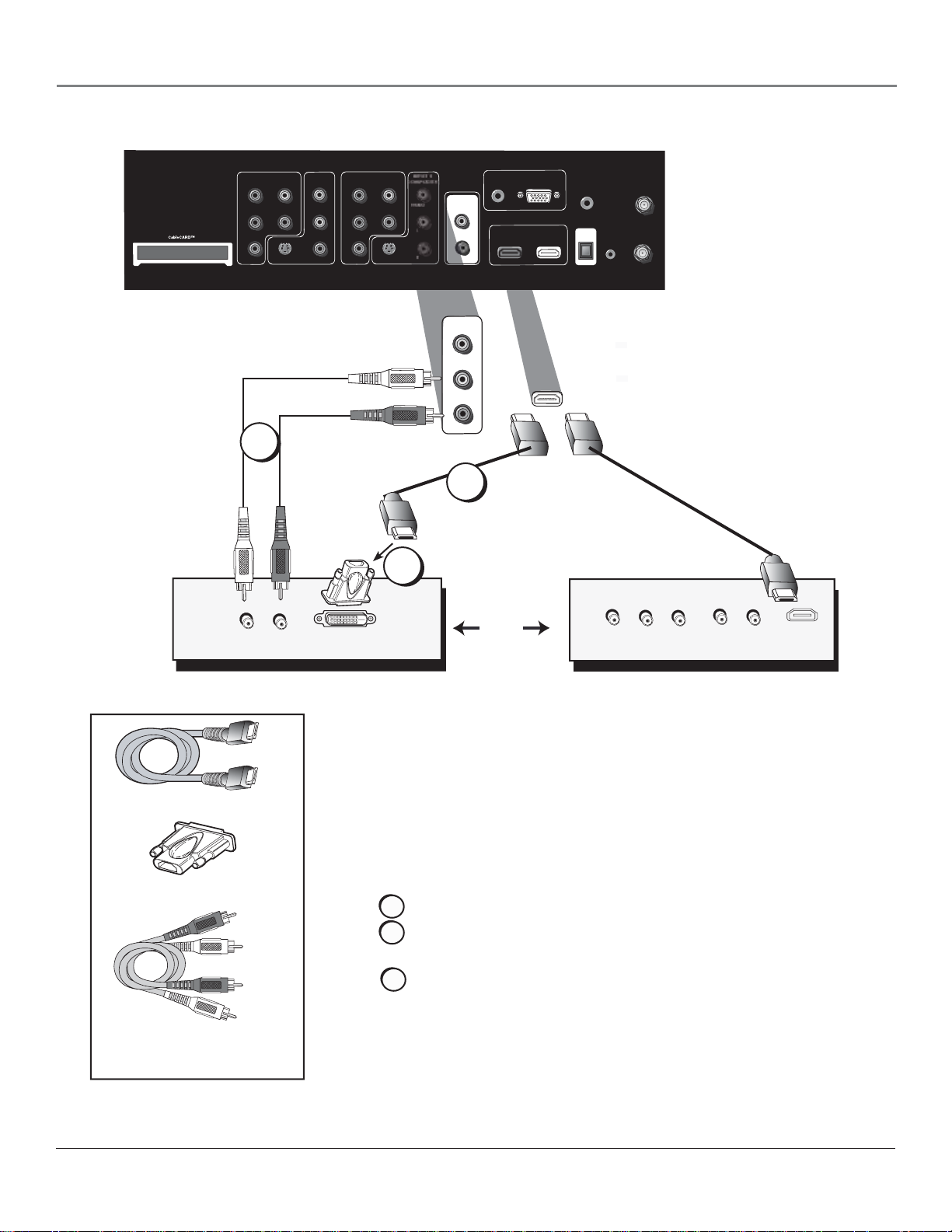
Choose Your Connection
There are several ways to connect your HDTV, depending on the components you want to connect and the quality of the signal you want
to achieve. The HDMI and component jacks are considered excellent; S-Video is very good; composite jacks are good, while connecting
components to the Antenna or Cable input is fair.
Please use the following chart to determine which connection is best for you. Proceed to the appropriate page and connect your TV.
Jacks Used Cables Needed Go to...
INPUT 1
COMPONENT/COMPOSITE
Y/VIDEO
L
Y Pb Pr
Audio R and L
Component video
pages 12-13
B
P
PR
S-VIDEO
R
INPUT 2
COMPOSITE
VIDEO
L
R
HDMI™
Video
Audio R and L
Audio
Audio/Video
S-Video
HDMI
OR
HDMI
HDMI/DVI™
adapter
pages 14-15
pages 16-17
Audio
Connecting an optional audio receiver:
After you connect your TV (choose an option above), go to page 18 for general information about
connecting an audio/video receiver.
HDMI, the HDMI logo, and High-Defi nition Multimedia Interface are trademarks or registered trademarks of HDMI Licensing LLC.
Chapter 1 11
Page 14
Connections & Setup
Y Pb Pr (Component Video) Connection
INPUT 2
COMPONENT/COMPOSITE
INPUT 3
COMPONENT/COMPOSITE
Y/VIDEO
PB
S-VIDEO
INPUT 1
Y/VIDEO
PB
PR
L
R
L
R
INPUT 4
COMPOSITE
VIDEO
L
R
FIXED/VARIABLE
AUDIO OUTPUT
AUDIO VGA/SVGA/XGA
L
HDMI 1 INPUT HDMI 2 INPUT
R
SVGA INPUT
WIRED
REMOTE
CONTROL
(IR)
DIGITAL
AUDIO
OUTPUT
(OPTICAL)
For Factory
use only
ANTENNA
INPUT
CABLE
INPUT
Note: This back panel graphic is
for representation only. Your back
panel might be different.
INPUT
VIDEO
OUTPUT
AUDIO
L
S-VIDEO
R
IN
COMPONENT VIDEO
YPbPr
AUDIO
VIDEO
L
R
AUDIO
LR
S-VIDEO
OUT
12 Chapter 1
Page 15

Connections & Setup
Green
Blue
Red
Component Video
cables (Y Pb Pr) are
color coded- Green,
Blue and Red
Red
White
Audio cables are color
coded- Red= right audio;
white= left audio
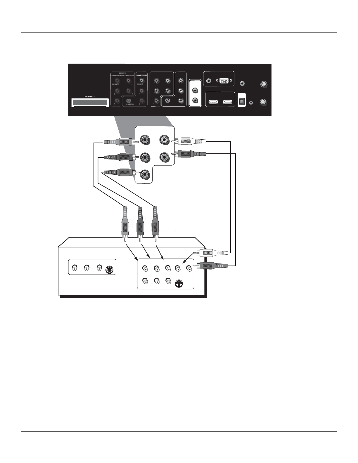
Connecting the Device
This connection allows you to connect a device that has Y Pb Pr jacks, for example, a
DVD player. If the device you are connecting also has S-Video or composite video, we
recommend you use the component video input for better quality.
Using the example of a DVD player:
1. If necessary, connect your cable and/or off-air antenna as described on page
9.
2. Connect your Y Pb Pr component video cables.
Connect three video cables or component video cables to the INPUT 1 Y/VIDEO
PB PR jacks on the back of the TV and to the Y PB PR outputs on the DVD player.
3. Connect your audio cables.
Connect the audio (white and red) cables to the INPUT 1 R and L Audio jacks on
the back of the TV and to the Audio Output jacks on the DVD player.
• If you are done
connecting devices to
your TV, go to page 19
to complete the Assisted
Setup.
• To continue connecting
devices, go to the next
page.
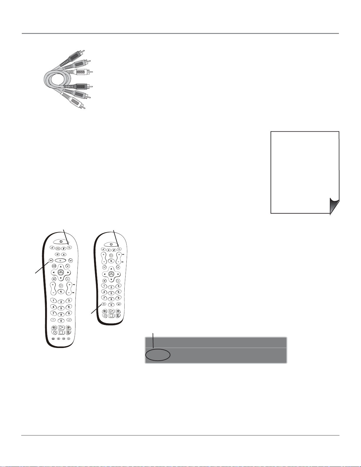
TV button
ON•OFF
INPUT
button
SAT•CABLE
INPUT
FORMAT
MENU
VOL
SUBCHANNEL
REVERSE
RECORD
VCR
AUDIO
GUIDE
GO BACK
MUTE
PLAY
STOP
CC PRESETS SOUND
TV
DVD
AUX
ANT•CABLE
INFO
CLEAR
CH
SKIP
INPUT
button
FORWARD
PAUSE
Use these buttons to view the picture
TV button
ON•OFF
SAT•CABLE
AUX
GO BACK
VOL
MUTE
FORMAT
MENU
INPUT
PLAY
REVERSE
RECORD
STOP
DVD
ANT•CABLE
FORWARD
PAUSE
Viewing the Picture from the Connected Device
The device in this connection is connected to the TV’s INPUT 1 jacks. To view this
device:
TV
1. Turn on the TV and the device you want to view, for example a DVD player.
CH
2. Press the TV button on the remote control to put the remote in TV mode.
INFO GUIDE
3. Press the INPUT button on the remote control to scroll through the Video Input
SUB
CH
CLEAR
Channels until you see Input 1 (Component) displayed in the channel banner.
Note: You can set up the TV to automatically tune to the correct device you want
to view. This is called Auto Tuning. See Chapter 3 for more information on Auto
Tuning.
Input channel appears here
12:39 PMProgram Title/Acquiring Channel
Input 1 (Component)
of the device connected to the TV. Your
remote model varies according to the
model of TV you have.
Chapter 1 13
Page 16

Connections & Setup
Audio/Video Connection
INPUT 1
COMPONENT/COMPOSITE
Y/VIDEO
B
P
P R
S-VIDEO
INPUT 2
COMPOSITE
VIDEO
L
R
S-VIDEO
OUTPUT
COMPONENT VIDEO
Y
VIDEO
L
R
Pb
AUDIO
L
INPUT 3
COMPONENT/COMPOSITE
Y/VIDEO
P
B
P R
S-VIDEO
INPUT 2
COMPOSITE
VIDEO
L
R
AUDIO
L
Pr
S-VIDEO
R
OUT
R
L
R
INPUT 4
COMPOSITE
VIDEO
L
R
INPUT
VIDEO
FIXED/VARIABLE
AUDIO OUTPUT
SVGA INPUT
AUDIO VGA/SVGA/XGA
L
HDMI 1 INPUT HDMI 2 INPUT
R
WIRED
REMOTE
CONTROL
(IR)
DIGITAL
AUDIO
OUTPUT
(OPTICAL)
Note: This back panel graphic is
for representation only. Your back
panel might be different.
AUDIO
S-VIDEO
L
R
IN
For Factory
use only
ANTENNA
INPUT
CABLE
INPUT
14 Chapter 1
Page 17
Connections & Setup
Red
Yellow
White
Composite cables are color codedYellow= video; Red= right audio; white=
left audio
Connecting the Device
.
This connection allows you to connect a device such as a VCR that has audio/video
outputs.
Using the example of a VCR:
1. Connect your cable and/or off-air antenna as described on page 9.
2. Connect your composite audio/video cables to the TV’s input.
Connect composite audio/video cables to the TV’s INPUT 2 jacks (R and L-Audio,
and Video) and to the VCR’s audio/video outputs..
• If you are done
connecting devices to
your TV, go to page 19
to complete the Assisted
Setup.
• To continue connecting
devices, go to the next
page.
TV button
ON•OFF
INPUT
button
SAT•CABLE
INPUT
FORMAT
MENU
VOL
SUBCHANNEL
REVERSE
RECORD
VCR
AUDIO
GUIDE
GO BACK
MUTE
PLAY
STOP
CC PRESETS SOUND
TV
DVD
AUX
ANT•CABLE
INFO
CLEAR
CH
SKIP
INPUT
button
FORWARD
PAUSE
SAT•CABLE
VOL
FORMAT
MENU
Use these buttons to view the picture
of the device connected to the TV. Your
remote model varies according to the
model of TV you have.
TV button
ON•OFF
TV
DVD
AUX
GO BACK
MUTE
ANT•CABLE
INPUT
PLAY
REVERSE
FORWARD
RECORD
PAUSE
STOP
Viewing the Picture from the Connected Device
The device in this connection is connected to the INPUT 2 jacks. To view this device:
1. Turn on the TV and the device you want to view.
CH
2. Press the TV button on the remote control to put the remote in TV mode.
3. Press the INPUT button on the remote control to scroll through the Video Input
INFO GUIDE
SUB
CH
CLEAR
Channels until you see INPUT 2 in the channel banner. See picture below for
location.
Note: You can set up the TV to automatically tune to the correct device you want
to view. This is called Auto Tuning. See Chapter 3 for more information on Auto
Tuning.
Input channel appears here
12:39 PMProgram Title/Acquiring Channel
Input 2
Chapter 1 15
Page 18
Connections & Setup
HDMI Connection
INPUT 1
COMPONENT/COMPOSITE
Y/VIDEO
P
B
PR
S-VIDEO
C
L
Audio Out
L
R
R
INPUT 2
COMPOSITE
VIDEO
L
R
INPUT 3
COMPONENT/COMPOSITE
Y/VIDEO
P
B
PR
Device with DVI
DVI Out
S-VIDEO
L
R
B
FIXED/VARIABLE
AUDIO OUTPUT
INPUT 4
COMPOSITE
VIDEO
L
R
A
SVGA INPUT
AUDIO VGA/SVGA/XGA
L
HDMI 1 INPUT HDMI 2 INPUT
R
OR
WIRED
REMOTE
CONTROL
(IR)
DIGITAL
AUDIO
OUTPUT
(OPTICAL)
For Factory
use only
ANTENNA
INPUT
CABLE
INPUT
Note: This back panel graphic is
for representation only. Your back
panel might be different.
Device with HDMI
Y
Video Out
Pb
R
Pr
Audio Out
L
HDMI Out
Connecting the Device
High-Defi nition Multimedia Interface (HDMI) is an uncompressed digital interface
that carries both video and audio data by way of an integrated mini-plug cable. Since
HDMI is based on Digital Visual Interface (DVI), the jack on the back of your TV is also
HDMI cable
compatible with devices that have a DVI jack.
Using the example of a set-top box:
• If your set-top box has a DVI jack, connect an HDMI cable and an HDMI/
HDMI/DVI adapter
Red
DVI adapter.
A. Connect an HDMI cable to the HDMI INPUT jack on the back of the TV.
B. Attach an HDMI/DVI adapter to the end of the HDMI cable, then connect the
White
adapter to the DVI Out jack on the back of the device.
C. Since you’re using an HDMI/DVI adapter, you need to connect Audio left and
right cables to the R and L jacks on the back of the device and to R and L Audio
jacks that aren’t in use on the back of the TV.
Audio cables are color
coded- Red= right audio;
white= left audio
After you’ve completed the on-screen Assisted Setup (page 19), go to the DVI Audio
Input option in the Advanced Audio menu to select which Audio Input jack you’re
using. In the example on the opposite page you would choose INPUT 4.
16 Chapter 1
Page 19
HDMI cable
Connections & Setup
Note: If the device you’re connecting has a digital audio output jack, connect a
digital audio cable from the device to an audio receiver for digital audio.
OR
• If your set-top box has an HDMI jack, connect an HDMI cable.
Connect an HDMI cable to the HDMI 1 INPUT (or HDMI 2 INPUT if your TV
has this jack and it’s more convenient) jack on the back of the TV and to the HDMI
Out jack on the back of the device.
TV button
ON•OFF
INPUT
button
SAT•CABLE
INPUT
FORMAT
MENU
VOL
SUBCHANNEL
REVERSE
RECORD
VCR
AUDIO
GUIDE
GO BACK
MUTE
PLAY
STOP
CC PRESETS SOUND
TV
DVD
AUX
ANT•CABLE
INFO
CLEAR
CH
SKIP
INPUT
button
FORWARD
PAUSE
SAT•CABLE
VOL
FORMAT
MENU
Use these buttons to view the picture of
the device you’ve connected to the TV
(your remote model varies according to
the model of TV you have).
TV button
ON•OFF
TV
DVD
AUX
GO BACK
MUTE
ANT•CABLE
INPUT
PLAY
REVERSE
FORWARD
RECORD
PAUSE
STOP
Viewing the Picture from the Connected Device
The device in this connection is connected to the HDMI jack. To view this device:
1. Turn on the TV and the device you want to view.
CH
2. Press the TV button on the remote control to put the remote in TV mode.
INFO GUIDE
3. Press the INPUT button on the remote control to scroll through the Video Input
SUB
CH
CLEAR
Channels until you see HDMI 1 Input displayed in the channel banner. See picture
below for location.
Note: You can set up the TV to automatically tune to the correct device you want
to view. This is called Auto Tuning. See Chapter 3 for more information on Auto
Tuning.
Input channel appears here
12:39 PMProgram Title/Acquiring Channel
HDMI 1 Input
• If you are done connecting
devices to your TV, go to
page 19 to complete the
Assisted Setup.
• To fi nd out more about
connecting audio/video
receivers, go to the next
page.
Chapter 1 17
Page 20

Connections & Setup
F
E
FIXED/VARIABLE
DIG
L
O
O
Advanced Audio Connection Information
With the audio versatility of your HDTV, you can choose various connection options depending on the type
and quality of sound that you want. From good to best sound, choose one of the options or refer to the user’s
manual of each device that you are connecting to get the best results.
• Use your TV’s internal speakers (good sound).
• Connect an audio receiver (speakers connected to receiver) to your TV (better sound).
• Connect an audio receiver (speakers connected to receiver) to your TV using the DIGITAL AUDIO OUTPUT
(OPTICAL) jack (best sound)
Red
White
Audio cables are color
coded- Red= right
audio; white= left
audio
INPUT 1
COMPONENT/COMPOSITE
Y/VIDEO
B
P
PR
S-VIDEO
L
R
INPUT 2
COMPOSITE
VIDEO
L
R
INPUT 3
COMPONENT/COMPOSITE
Y/VIDEO
P
B
PR
S-VIDEO
L
R
INPUT 4
COMPOSITE
VIDEO
L
R
FIXED/VARIABLE
IXED/VARIABL
SVGA INPUT
AUDIO VGA/SVGA/XGA
HDMI 1 INPUT HDMI 2 INPUT
FIXED/VARIABLE
AUDIO OUTPUT
L
R
WIRED
REMOTE
CONTROL
(IR)
DIGITAL
ITA
AUDIO
AUDI
OUTPUT
UTPUT
For Factory
use only
DIGITAL
AUDIO
OUTPUT
(OPTICAL)
ANTENNA
INPUT
CABLE
INPUT
Connecting Your TV to an Audio/Video Receiver
For better sound quality than the TV’s internal speakers, connect to an audio receiver using audio cables to the
TV’s AUDIO OUTPUT jacks.
• Use the FIXED/VARIABLE AUDIO OUTPUT for a more advanced connection. Connect the FIXED/
VARIABLE AUDIO OUTPUTS from the TV to an A/V receiver using audio cables.
Be sure to go to the Fixed/Variable Out screen in the Advanced Audio menu and select whether you want the
FIXED/VARIABLE AUDIO OUTPUT jacks to send fi xed or variable volume audio.
• Variable Output provides variable-level audio output. Volume levels are controlled by the TV’s volume.
• Fixed Output provides fi xed-level audio output from the TV. This audio output is ideal for connecting
to an A/V receiver that has its own volume control.
Connecting Your TV to a Receiver with Dolby® Digital
If you own a receiver with Dolby® digital decoding or PCM (Pulse-Code Modulation) that uses an optical cabletype input, connect an optical cable for excellent audio quality.
• Connect one end of the optical cable to the DIGITAL AUDIO OUTPUT (OPTICAL) jack on your TV and
to the Digital Optical Input jack on your receiver/amplifi er receiver.
Digital Optical
cable
• If your receiver can decode Dolby digital and PCM, go to the Audio menu, select Advanced Audio
menu, then Digital Audio Output. Select AutoSelect (recommended) or PCM.
• If your receiver can decode only PCM, select PCM.
Dolby and the double-D symbol are registered trademarks of Dolby Laboratories.
18 Chapter 1
Page 21

Connections & Setup
Plug in the TV
Plug the fl at end of the cable into the power jack on the back of the TV. Then plug the other end of the power
cord into an appropriate wall outlet. Be sure to insert the plug completely. Do not plug the TV into an outlet
controlled by a light switch.
Note: When you fi rst plug your TV into an outlet, the Power indicator on the front panel will light and
blink for approximately 30 seconds and then go off during the initialization of the TV. This happens only
when the TV is unplugged and plugged back in. The TV can only be turned on after the Power indicator
goes off.
Put Batteries in the Remote
• Remove the battery compartment cover from the back of the remote by
pushing down on the tab and lifting cover.
• Insert 2 fresh “AA” batteries. Make sure the polarities (+ and -) are aligned
correctly with the polarities inside the remote.
• Replace the cover.
Turn on the TV
TV
MENU
Use these buttons during the Assisted Setup
CLEAR
Press TV on the remote, or press the Power button on the TV’s front panel.
Note: Pressing the TV button turns on the TV and puts the remote into TV
mode so that the remote operates the TV’s functions.
Use the Remote Control to Complete
the Assisted Setup
The technical term is “Navigation” – how you move through the on-screen menus.
The method is the same throughout the menu screens: highlight your choice and
select it.
To use the TV’s menus, fi rst press the TV button on the remote control to put
the remote in TV mode. When the Assisted Setup screen appears, use the arrow
buttons to highlight one of the items listed in the menu. Use the up or down
arrow button to move up or down. Use the right or left arrow button to move
right or left.
To select the item that you’ve highlighted, press OK.
Note: Highlighted means that the menu item stands out from
other menu items on the list (appears darker, brighter, or a
different color).
Complete the Assisted Setup
Tip
To access the initial setup menus at a later time, press
MENU, choose Setup Options, then Assisted Setup.
Chapter 1 19
Your TV’s menu system allows you to customize your TV’s features. On-screen
information helps you choose settings to match your setup. The fi rst time you
turn on your TV, the Assisted Setup screen appears automatically. Press OK to
begin the setup.
Page 22

Connections & Setup
Main Menu
4
Go Back
0
Continue Setup
1
Cancel Setup
2
Go Back
0
Continue Setup
1
Cancel Setup
2
Setup Options4Assisted Setup 4Menu Language
English
Highlight with the 5and 6 arrows. Select with the OK button.
Español
Resalte con las flechas 5 y 6. Seleccione con el botón OK.
Français
Mise en surbrillance avec 5 et 6. Sélection avec OK.
Press 5or 6to point to an option, then press OK to
select it. Press 4 to return to the menu.
Main Menu
4
Channel Setup
Select channels to search:
Digital channels
Analog channels
Select other search options:
Detect antenna or cable signal
Search channels already in my channel list(s)
Remove scrambled digital cable channels
Check fewer boxes to make the search faster (but less
complete) and vice versa. A complete search takes about
50 minutes.
To add a channel that Channel Search didn't find, clear all
menus and tune to the channel with the number keys.
Start Search
Two lines of help text will appear in this area to explain the
feature and instruct the user on how to use it.
Select input to search:
Cable Input
Antenna Input
Tip
The fi rst Channel Search can take up to 20 minutes if
the TV is searching for analog and digital channels,
and cable and antenna inputs are being searched.
You may want to leave and come back later.
Set the Menu Language
Press the right arrow button, then press OK to select English and continue to the
next step. Press the down arrow button to choose another language, then press OK to
continue.
Complete the Channel Search
Even though this initial channel search can take several minutes, you must complete it in
order for your TV to display channels and programming information. Make sure you’ve
connected your TV to cable and/or off-air signals before you begin the channel search.
All the options are selected for you to ensure a full channel search is completed. Press
the right arrow button. An alert screen appears to allow you to start a channel search or
customize the options.
Press OK to start a channel search or if you want to change some of the options, use the
arrow buttons to highlight those options. Press OK to check or uncheck an option. Then
highlight Start Search and press OK to start the channel search.
When the channel search is complete a message screen appears. Press OK to continue.
Notes: If you skip Channel Search now, you can access it later through the Channel
Setup menu. For more detailed instructions, refer to Chapter 4 of the User’s Guide.
If a cable box is connected to your TV’s CABLE INPUT, or the CableCARD slot is
in use, don’t check the Cable Input box.
Choose Setup Options
Quick Startup is a power saving feature. Select to enable or disable Quick Startup. Decide
which option is best for you. Enabling Quick Startup allows you to turn on the TV faster
than if disabled. If a CableCARD is in use, Quick Startup is always enabled and cannot be
changed. Press OK to continue.
Several more screens appear that give you basic tips about using your TV. Read through
the information and continue to press OK until the screens disappear.
Note: When you disable Quick Startup it adds approximately 30 seconds to the TV’s
turn on time.
20 Chapter 1
Page 23

Connections & Setup
What To Expect
Watching TV
If you have both analog and digital cable channels these will be put into the same channel list. To tell the
difference between these channels, press the INFO button and look in the channel banner for these things: a
subchannel, the format, an A or D (analog or digital) icon and resolution the TV is receiving.
• Analog channels only display one channel number. Digital channels received through the digital cable
card also have one channel number. Digital channels received through cable or an off-air antenna might
have a primary channel and a subchannel. In the example below, 6 is the primary channel; 1 is the
subchannel.
• Analog channels are sent in a 4 x 3 format. Digital channels can be sent in a format of 4 x 3, but usually
16 x 9.
• Analog channels are sent in a resolution up to 480i. Digital channels are sent in a resolution of 480i,
480p, 720p, 1080i, or 1080p.
Channel number
Ch 6-1 DNLJ
D
Listening to English in SRS
MPAA - Not Rated
Channel format and resolution
12:39 PM
12:30 AM
16x9 Normal 1080i HDTV
00:30Program Title/Acquiring Channel
Cable Input
12:00 PM - 1:00 PM
Changing Channels
Depending upon the type of signals you have connected to your HDTV, you might notice that the channels
change slower than you’re used to. This is perfectly normal. Digital cable channels sometimes take longer to
tune.
Some channels might be found during the channel search that aren’t available. Some channels are enabled by
the cable company that don’t carry programming, such as video-on-demand. When channels are unavailable,
your TV’s screen displays Weak or No Signal. You probably want to remove these so they no longer appear in
your channel list. Remove these in the Channel Setup menu. Go to page 45 for more information.
Next Steps
Now that you’ve fi nished the Assisted Setup, you’re ready to watch TV. This might be a good time to program
your remote control. The remote control that came with this TV can be programmed to operate other
devices. Go to the next chapter to fi nd out how to program your remote. Continue to the next few pages to
learn more about the back panel and front of your TV.
• Chapter 2: Using the Remote Control
• Chapter 3: Using the TV’s Features
• Chapter 4: Using the TV’s Menu System
• Chapter 5: Other Information
Chapter 1 21
Page 24
Connections & Setup
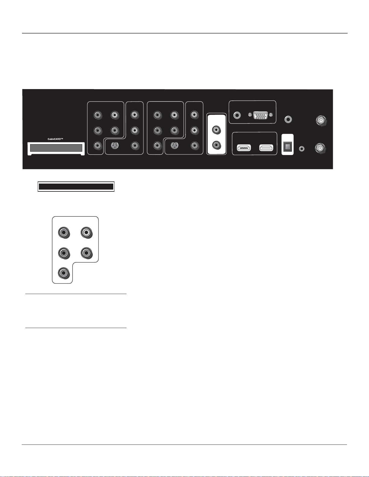
Explanation of Jacks
The diagrams below illustrate jacks found on the back of the TV. When connecting cables, be sure to
connect corresponding outputs and inputs (video input into video output, right audio input into right audio
output, etc.).
INPUT 1
COMPONENT/COMPOSITE
Y/VIDEO
P
PR
CableCARD™
INPUT 1
COMPONENT/COMPOSITE
Y/VIDEO
B
P
PR
L
R
B
L
R
S-VIDEO
Tip
Inputs 1 and 3 can be used as either component
video (Y PB PR ) inputs or composite video
(Y/Video) inputs.
INPUT 2
COMPOSITE
VIDEO
L
R
CableCARD
INPUT 3
COMPONENT/COMPOSITE
Y/VIDEO
B
P
PR
S-VIDEO
Allows you to use a digital cable television card to receive digital cable
COMPOSITE
L
R
INPUT 4
VIDEO
L
R
FIXED/VARIABLE
AUDIO OUTPUT
L
R
SVGA INPUT
AUDIO VGA/SVGA/XGA
HDMI 1 INPUT HDMI 2 INPUT
WIRED
REMOTE
CONTROL
(IR)
DIGITAL
AUDIO
OUTPUT
(OPTICAL)
For Factory
use only
ANTENNA
INPUT
CABLE
INPUT
services, including premium and HDTV cable channels, without the need for a set-top
box. Go to page 10 for information on using the CableCARD slot.
INPUT 1 and 3 COMPONENT/COMPOSITE INPUTS Provides connection to
an (analog) video device with either composite or component outputs such as a VCR or
DVD player.
• R Audio provides right audio connection and connector is usually red.
• L Audio provides left audio connection and connector is usually white.
• Y/Video PB PR Unlike a single video input, component (Y PB PR) video maintains
the video signal as three separate parts through these three jacks. To ensure maximum
picture quality, use three video cables or component video cables for the Y PB P
connections. Accepts 480i, 480p, 720p, and 1080i signals. If you’re connecting to a
device with a Video jack instead, you can still use the Y/Video jack.
Note: Also, remember to connect the left and right audio cables because the Y, Pb, Pr
cables carry only the picture signal, not the sound.
INPUT 3 COMPONENT/COMPOSITE INPUT Provides connection to an
additional optional video device, such as a DVD player or satellite receiver. The jacks are
the same as described above for INPUT 1.
R
22 Chapter 1
Page 25

Connections & Setup
S-VIDEO
INPUT 2
COMPOSITE
VIDEO
L
R
INPUT 4
COMPOSITE
VIDEO
VIDEO
L
L
INPUT 2 and 4 COMPOSITE INPUT S Connect an NTSC (analog) device. These
jacks are used for most audio/video connections between devices. The audio/video jacks
are often color coded (yellow for video, red for right audio, and white for left audio).
• R Audio provides right audio connection and connector is usually red.
• L Audio provides left audio connection and connector is usually white.
• V (Video) provides composite video connection and connector is usually yellow.
• S-VIDEO Lets you connect an S-Video cable for better picture quality to a device
with S-Video capability, such as a VCR or DVD player. When using S-Video, make
sure to connect the two audio cables as well as the
S-Video connector.
The S-Video jack provides better picture quality than the composite video jacks
because the color (chrominance, also called chroma) part of the signal is separated
from the black and white (luminance) part of the picture.
INPUT 4 COMPOSITE INPUT Provides connection to an additional optional video
device, such as a DVD player or satellite receiver. The jacks are the same as described
above for INPUT 2.
S-VIDEO
S-VIDEO
AUDIO VGA/SVGA/XGA
HDMI 1 INPUT
R
FIXED/VARIABLE
AUDIO OUTPUT
L
R
SVGA INPUT
R
HDMI 2 INPUT
FIXED/VARIABLE AUDIO OUTPUTS
• L and R Provides right front and right rear mixed sound to the right input, and left
front and left rear mixed sound to the left input.
SVGA INPUT (might not be available on your TV)
• VGA/SVGA/XGA Connect your device with a VGA, SVGA, or XGA output, to
this jack using a 15 pin D-sub cable.
• AUDIO (Stereo mini jack) Use to obtain sound when a device is connected to
the SVGA jack. Use a 3.5 mm stereo mini pin cable (sometimes referred to as 1/8”
stereo mini pin) to connect a device to your TV.
HDMI 1 and 2 INPUTS (some TV models only have one HDMI Input) HighDefi nition Multimedia Interface/Digital Visual Interface Provides an uncompressed
digital interface that carries both video and audio data by way of an integrated mini-plug
cable. Since HDMI is based on Digital Visual Interface (DVI), the jack on the back of
your TV is also compatible with DVI devices.
Note: If you connect a device with a DVI jack to one of the HDMI inputs, you’ll
need an HDMI to DVI adapter. Also, connect audio cables to an input that is not
in use. An example is shown on page 16. Then go to the Advanced Audio menu and
select DVI Audio Input to choose the input you’re using to receive audio.
Continues on next page...
Chapter 1 23
Page 26

Connections & Setup
WIRED
REMOTE
CONTROL
(IR)
DIGITAL
AUDIO
OUTPUT
(OPTICAL)
ANTENNA INPUT
CABLE INPUT
WIRED REMOTE CONTROL (IR) (available on some models) This jack is for
connecting a wired remote control system, which is primarily for professional installers. If
you’re using the remote that was included with your TV, don’t plug anything into this jack
or the TV won’t respond to the remote.
DIGITAL AUDIO OUTPUT (OPTICAL) Use a digital optical cable (or SPDIF
cable) to connect your TV to a compatible Dolby Digital or PCM receiver or decoder.
Dolby Digital Technology offers theatre-quality sound (six audio channels). If you own a
receiver that uses an optical cable input, you can use an optical cable to connect the TV to
that receiver for the best sound quality. Go to the Digital Audio Out screen in the Audio
menu to select Auto Select or PCM as the output for this jack.
Note: This TV’s optical digital output jack fully complies with the international
standard governing this type of jack (IEC958), and is designed for connection to
a Dolby Digital (AC-3® or PCM) receiver or decoder. Older equipment, some of
which is not fully compliant with IEC958, may not be compatible with the Dolby
Digital bitstream. Such a connection using anything other than a Dolby Digital
(AC-3 or PCM) receiver or decoder could create a high noise level, causing damage to
headphones or speakers.
ANTENNA INPUT Used to connect a coaxial cable to receive the signal from an
off-air antenna.
CABLE INPUT Used to connect a coaxial cable to receive the signal from cable or a
cable box.
24 Chapter 1
Page 27

Connections & Setup
The Front of Your TV
Front/Side Input Jacks
The TV has front/side input jacks for convenience in connecting a camcorder, digital camera, or video game system.
Look for a hinged door and press to open the cover. Some models have touch sensor buttons. Please note the
illustration below is just an example of how these jacks might appear.
Notes: When you plug in headphones, the TV’s internal speakers are muted. Use the VOL up or down button to
control the volume.
When connecting a device that uses a monaural cable, such as some camcorders, use the L/MONO input jack to get
sound from both speakers.
S-VIDEO
R
E
W
O
P
+
L
O
V
—
L
O
HEADPHONE
V
H
C
H
C
U
N
E
M
AUDIO IN VIDEO
L/MONO R IN
Power button
and indicator
MENU /OK
CH
CH
VOL
VOL
Notes: The front panel illustration shows a typical front panel layout. The exact look may
be different from your TV.
If you use the Front Button Block feature, the front panel no longer provides access to the
menus. The Front Button Block feature disables all front panel buttons but not the jacks.
For more information, see Chapter 3.
Front Panel
If you cannot locate your remote, you can use the front panel of your TV to operate many of the TV’s features.
Power Indicator Light Status
On TV is on
Off TV is off (standby mode)
Blinks Light blinks 5 times, pauses, and blinks again 5 times:
Lamp is trying to turn on. If the TV doesn’t turn on
after 5 minutes and then the light blinks steadily for
one minute, one of the following options is possible:
Lamp door may be open. Face the back of the TV.
Locate the door at the bottom of the TV and close it.
Turn off the TV and turn back on. The lamp should
turn on.
Lamp may be dead. You can replace the lamp
yourself. Go to page 67 for lamp replacement
information.
MENU/OK Brings up the Main menu. When the menu system is displayed, pressing MENU/OK selects highlighted
items.
CH6 Scans down through the channel list. In the menu system, it moves the highlight down and adjusts menu controls.
CH5 Scans up through the channel list. In the menu system, it moves the highlight up and adjusts menu controls.
VOL3 Decreases the volume. In the menu system, it moves the highlight left to items and adjusts menu controls.
VOL4 Increases the volume. In the menu system, it moves the highlight right to items and adjusts menu controls.
(Power button and indicator) Turns the TV on and off. The indicator lights when TV is on. Your HDTV’s lamp has a
cool-down period when the TV is turned off, and a warm up period when the TV is turned on. If you try to turn the TV on
during a cool-down, you will hear audio and then the picture will be displayed after a few moments. This could take up to one
minute. For different light status of the indicator, see above.
(Available on some models) Press this icon (or the power button) to illuminate the buttons on the front panel. The
channel banner will appear on screen. The illuminated buttons are touch sensors, press them to control your TV.
Chapter 1 25
Page 28

This page left intentionally blank.
Page 29

Chapter 2: Using the Remote Control
Chapter Overview:
• The Buttons on the Remote Control
• Programming the Remote to Operate Other Devices
• How To Use the Remote After You’ve Programmed It
• Volume Punchthrough Feature
• Using the INPUT Button
• Remote Code List
Changing Entertainment. Again.
rca.com/television
Graphics contained within this publication are for representation only. 27
Page 30

Using the Remote Control
ON•OFF
SAT•CABLE
VOL
FORMAT
MENU
INPUT
REVERSE
RECORD
AUX
GO BACK
MUTE
PLAY
STOP
DVD
ANT•CABLE
FORWARD
PAUSE
Remote model
R401A1
TV
INFO GUIDE
CLEAR
CH
SUB
CH
SAT•CABLE
INPUT
FORMAT
MENU
VOL
SUBCHANNEL
VCR
AUDIO
REVERSE
RECORD
CC PRESETS SOUND
ON•OFF
GUIDE
GO BACK
MUTE
PLAY
STOP
DVD
AUX
ANT•CABLE
SKIP
FORWARD
PAUSE
Remote model
R602A1
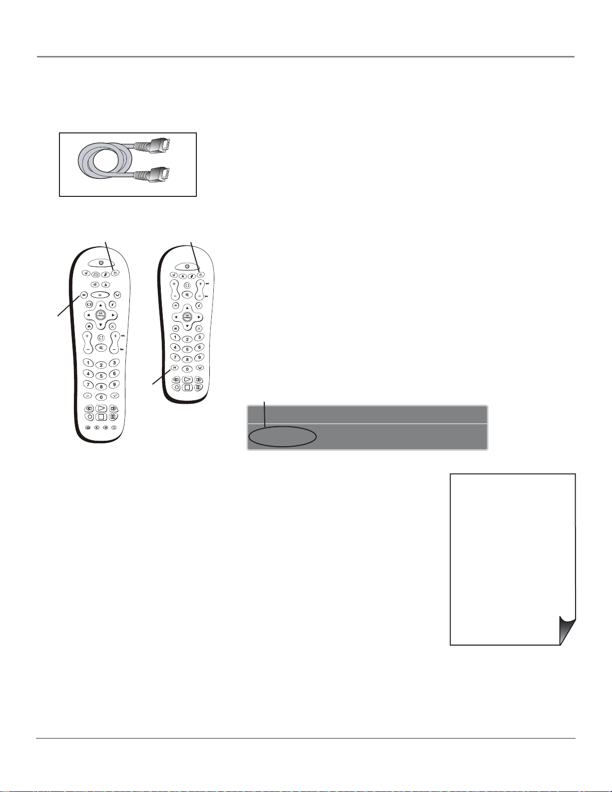
The TV models covered in this User’s Guide
come with one of the two remotes shown.
TV
INFO
CLEAR
CH
The Buttons on the Remote Control
Arrows (up, down, left, right) Used to move through the on-screen menus. (For the
use of FORMAT and SUB CH on remote R401A1, see those labels).
Backlight (only available on remote R602A1) Press to illuminate the remote
control buttons. Any press thereafter turns the backlight on. To conserve battery power,
the light turns off after several seconds. Press this button again to turn the backlight off.
(0-9) Number Buttons Enter channel numbers and time settings. Also used in the TV
menu to make selections.
To enter a digital channel with a sub-channel, enter the main channel, then to enter
the sub-channel, press the SUB CH (right arrow) button on remote R401A1, or
SUBCHANNEL on remote R602A1, and press OK.
ANT•CABLE Switches between Antenna and Cable Input. When tuned to an input,
press to go back to the most recently used tuner (Antenna or Cable Input).
AUDIO (only available on remote R602A1) Places the remote in audio mode to
operate a device (such as a audio receiver or amplifi er receiver) that you’ve programmed to
work with this button. This button lights when you press a valid button in AUDIO mode
(see Modes of Operation on page 32 for more details).
AUX Places the remote in auxiliary mode to operate a device (such as a cable box,
satellite receiver, VCR, DVD, or audio receiver) that you’ve programmed to work with
this button. For remote R602A1, AUX by default is programmed to an RCA HD tuner.
For remote R401A1, AUX by default is programmed to an RCA VCR. This button lights
when you press a valid button in AUX mode (see Modes of Operation on page 32 for more
details).
Tip
To turn off most RCA devices that are connected to
the TV, press ON•OFF twice within two seconds and
hold remote steady until the mode indicator turns
off.
CC (only available on remote R602A1) In TV mode, toggles closed captioning on
and off, if available for the channel you’re tuned to. In DVD mode, displays Subtitle
options, if available, for the DVD you’re watching.
CH + or CH – Scrolls up or down through the channel or input list. Press once to
change the channel up or down; press and hold to continue changing channels. In DVD
mode, if programmed, advances or reverses the chapters with some DVD players.
CLEAR Removes on-screen menus and displays. Cancels the commercial skip timer if
it is set.
DVD Places the remote in DVD mode. If Auto Tuning is enabled, pressing the DVD
button turns on the TV and tunes to the correct Video Input Channel for RCA devices.
This button lights when you press a valid button in DVD mode (see Modes of Operation
on page 32 for more details).
FORMAT Toggles through the video screen formats: Normal, Stretch, Squeeze, Zoom,
and Auto Format.
FREEZE Freezes entire screen. Press any button to remove the freeze.
GO BACK Returns you to the previous channel or previous screen in the menu system.
GUIDE If programmed, displays the Program Guide when a compatible set-top box
(e.g. a digital cable box or satellite receiver) is connected.
28 Chapter 2
Page 31

Using the Remote Control
INFO Displays the Channel Banner with channel and viewing information. Press again to remove the banner.
INPUT Toggles through the TV’s available input sources (INPUT 1, INPUT 2, INPUT 3, INPUT 4, Front Input, HDMI1, HDMI2,
SVGA, and last-active channel. Note HDMI2 and SVGA might not be available for your TV).
MENU Makes Main Menu appear and disappear.
MUTE Reduces the TV’s volume to its minimum level. Press again to restore volume. The Audio Output menu must be set to Variable
Level, Speakers On to control the TV’s volume. To program this button to work with an audio system, follow the instructions for Volume
Punchthrough Feature on page 32.
OK When a menu item is highlighted, press OK to select the item.
ON•OFF Turns the TV on or off. Your HDTV is equipped with a special lamp system. In order to preserve the life of the lamp, the TV
must warm up and cool down properly when you turn the TV on and off. When you turn the TV off, the screen turns blue and fades to
black. While the screen is blue, you can still turn the TV back on. If the screen is black when you try to turn it on, the TV’s lamp may be in
its cool-down cycle. The TV’s audio comes on, then the picture is displayed after a few moments.
In other modes (SAT•CABLE, VCR, DVD, AUX, AUDIO), and if programmed, turns the device on and off.
PRESETS (only available on remote R602A1) In TV mode, toggles through the Picture Presets for the input you’re currently tuned. In
DVD mode, displays the different angles, if available, for the DVD you’re watching.
REVERSE, PLAY, FORWARD, RECORD, STOP, PAUSE If programmed, provides transport control for some remote-controllable
VCRs, DVD players, satellite receivers, etc. The RECORD button has a safety feature which means you must press the button two times to
record.
SAT•CABLE (Satellite•Cable) Places the remote in SAT/CABLE box mode. If Auto Tuning is enabled, turns on the TV and tunes it
to the satellite or cable box Video Input Channel for RCA devices. This button lights when you press a valid button in SAT•CABLE mode
(see Modes of Operation on page 32 for more details).
SKIP (only available on remote R602A1) Press once before changing channels and the TV returns to the original channel after 30
seconds. Press repeatedly to add more time. With no menus on-screen, press CLEAR to cancel.
SOUND (only available on remote R602A1) In TV mode, on digital channels/inputs, toggles through the available Audio Language/
Modes. For analog channels, toggles SAP on or off. If you change channels/inputs, the default for Audio Language/ Mode is restored. Does
not affect default menu settings for SAP or Audio Lang./ Mode. In DVD mode, displays the different audio options, if available, for the
DVD you’re watching.
SUB CH or SUBCHANNEL When entering a digital channel that has a subchannel, press this button to access the subchannel entry
fi eld. Once the channel is entered, press the button to tune to the channel.
TV Places the remote in TV mode. Turns on the TV and tunes to the last-viewed TV channel or input. This button lights when you press
a valid button in TV mode (see Modes of Operation on page 32 for more details).
VCR (only available on remote R602A1) Places the remote in VCR mode. If Auto Tuning is enabled, turns on the TV and tunes to the
VCR Video Input Channel for RCA devices. This button lights when you press a valid button in VCR mode (see Modes of Operation on
page 32 for more details).
VOL – or VOL + Decreases or increases the TV’s volume. The TV Audio Output menu must be set to Variable Level, Speakers On to
control the TV’s volume. To program this button to work with an audio system, follow the instructions for Volume Punchthrough Feature on
page 32.
Chapter 2 29
Page 32

Using the Remote Control
ON•OFF
SAT•CABLE
VOL
FORMAT
MENU
INPUT
REVERSE
RECORD
AUX
GO BACK
MUTE
PLAY
STOP
DVD
ANT•CABLE
FORWARD
Remote model
R401A1
PAUS E
TV
INFOGUIDE
CLEAR
CH
SUB
CH
SAT•CABLE
INPUT
FORMAT
MENU
VOL
SUBCHANNEL
ON•OFF
VCR
AUDIO
GO BACK
REVERSE
RECORD
CC PRESETS SOUND
GUIDE
MUTE
PLAY
STOP
DVD
AUX
TV
ANT•CABLE
INFO
CLEAR
CH
SKIP
FORWARD
PAUSE
Remote model
R602A1
The darkened buttons are the device buttons
that can be programmed.
Programming the Remote to Operate
Other Devices
The universal remote can be programmed to operate many brands of remote-controllable
VCRs, audio devices, DVD players, cable boxes, satellite receivers and other devices. In
addition to being programmed to operate your television, it’s already programmed to
operate some RCA devices.
A second and third RCA TV can be programmed to any device button, except the TV
button.
Notes: The TV button can’t be programmed on this remote to control any device; it
controls only this TV.
The remote may not be compatible with all models of all brands of devices. It also
may not operate all functions of your device.
Find Out If You Need to Program the Remote
To determine whether the universal remote needs to be programmed to operate one of the
devices connected to your TV, such as a VCR, do the following:
1. Turn on the device (in this example, a VCR).
2. Point the remote at the device.
3. Press the corresponding device button (in this example, VCR).
4. Press ON•OFF to see if the VCR responds. If the VCR doesn’t respond, you need to
program the remote to operate it.
SAT•CABLE
VOL
FORMAT
MENU
INPUT
REVERSE
RECORD
ON•OFF
AUX
GO BACK
MUTE
PLAY
STOP
DVD
ANT•CABLE
FORWARD
PAUSE
TV
CLEAR
CH
INFO GUIDE
SUB
CH
SAT•CABLE
INPUT
FORMAT
MENU
VOL
SUBCHANNEL
VCR
AUDIO
GO BACK
REVERSE
RECORD
CC PRESETS SOUND
ON•OFF
GUIDE
MUTE
PLAY
STOP
DVD
AUX
TV
ANT•CABLE
SKIP
FORWARD
PAUSE
You’ll use these darkened buttons for Direct
Entry.
INFO
CLEAR
Programming the Remote
There are three ways to program the remote control to operate other devices: Direct
Entry, Manual Code Search, and Automatic Code Search. If you have recently purchased
the device you want to control or if the device has many codes, you might want to try the
manual code search fi rst.
Using Direct Entry
1. Turn on the device you want to control.
2. Look up the brand and code number(s) for the device in the code list at the end of
CH
this section.
3. On your remote control, simultaneously press and hold the ON•OFF and MUTE
buttons (approximately 3 seconds) until a device button remains lit. Then release the
buttons.
4. Press and release the device button (SAT•CABLE, VCR, DVD, AUX or AUDIO)
you want to program.
5. Enter a three digit code from the code list.
30 Chapter 2
Page 33

Using the Remote Control
6. To test the code you’ve programmed for that device button, point the remote at the device and then press ON•OFF
to see if the device responds to the remote control.
If the device turns off, you’ve entered the correct programming code for your device. Circle the code you entered for
future reference.
If the device doesn’t turn off, repeat these steps until you’ve tested all codes for your device’s brand or try to run a
manual code search.
Using Manual Code Search
Note: Before using manual code search, you must use Direct Entry fi rst. This lets the remote know which type of device
to begin searching codes. Then proceed with the following steps.
1. Turn on the device you want to control.
2. On your remote control, simultaneously press and hold the ON•OFF and MUTE buttons (approximately 3
seconds) until a device button remains lit. Then release the buttons.
3. Press and release the device button (SAT•CABLE, VCR, DVD, AUX or AUDIO) you want to program.
4. Repeatedly press and release the ON•OFF button, watching for the device to respond. If it does turn off, press and
release the OK button within 3 seconds to save the code. If you accidentally passed the code before saving it, press
the left arrow button to backtrack through the codes; then use the right arrow button to go forward through the
codes again.
When all codes have been searched, the device button fl ashes 3 times, then the remote exits manual code search and
returns to normal operation.
Using Automatic Code Search
1. Turn on the device you want to control.
2. On your remote control, simultaneously press and hold ON•OFF and MUTE (approximately 3 seconds) until a
device button remains lit. Then release the buttons.
3. Press and release the device button you want to program.
4. Press and release the ON•OFF button once. There is a delay of approximately 6 seconds before the remote starts the
code search.
The device buttons blinks each time the remote control sends a code to test with your device. Keep pointing the
remote at the device.
5. Once the device turns off, quickly press the OK button to save the code. If you accidentally passed the code before
saving it, press the left arrow button to backtrack through the codes; then use the right arrow button to go forward
through the codes again.
When all codes have been searched, the device button fl ashes 3 times, then the remote exits automatic code search and
returns to normal operation.
How to Use the Remote After You’ve Programmed It
Once the remote has been programmed successfully, you are ready to use it to operate your devices.
To Operate the Device:
1. Press the appropriate device button (SAT•CABLE, VCR, DVD, AUX or AUDIO) to set the remote to control the
device, for example, press DVD to control your DVD player.
2. Press ON•OFF to turn the device ON or OFF.
Continues on next page...
Chapter 2 31
Page 34

Using the Remote Control
3. Use the remote buttons that apply to that device.
Notes: The remote control may not be compatible with all brands and models of devices.
Modes of Operation
The button corresponding to the mode the remote is in lights up when you press any button that works in
that mode. For example, if you’re in TV mode and you press the VOL+ button, the TV button lights up.
This tells you that the command to increase the volume is being sent to the TV (and not the satellite receiver,
for example).
Volume Punchthrough Feature
You may fi nd this feature helpful if you’ve connected your devices to an audio system, and you want to
use the TV’s remote control to operate the volume for a device that is connected to the audio system. An
example follows:
Let’s say you’ve connected your DVD player to your audio system. You’ve also programmed your TV remote
control to operate your DVD player. Since the DVD player sends its volume through the audio system, you
would have to bounce back and forth between two remote controls: the audio system’s remote to adjust the
volume and the TV’s remote control to operate the DVD player.
The Volume Punchthrough feature eliminates the need for you to use two remote controls and saves a button
press when you’re using the TV remote to adjust the volume. In effect, you are telling the TV remote to
retrieve and send volume commands from the audio system whenever the TV remote is in DVD mode.
Therefore, after you’ve successfully set up the Volume Punchthrough feature, whenever the TV remote is in
DVD mode (press the DVD button) and you want to adjust the volume, you only have to press the VOL
+/- or MUTE buttons. Follow the instructions below to set up Volume Punchthrough.
1. On your remote control, simultaneously press and hold the ON•OFF and MUTE buttons
(approximately 3 seconds) until a device button remains lit. Then release the buttons.
2. Press and hold the MUTE button until the device button blinks off, then release the MUTE button.
3. Press and release the device button that you programmed to operate the audio system (receiver or
amplifi er).
4. Press and release the MUTE button.
5. Now, test it by turning on your audio system.
6. Turn on the device that is connected to the audio system (satellite receiver, for example).
7. Put the TV’s remote in SAT•CABLE mode by pressing the SAT•CABLE button.
8. Press VOL+ or VOL-. The volume from the audio system should increase or decrease accordingly.
32 Chapter 2
Page 35

Using the Remote Control
Deleting ALL Volume Punchthrough Commands
To delete all programmed Volume Punchthrough settings and return the remote control back to the factory default:
1. Simultaneously press and hold the ON•OFF and MUTE buttons (approximately 3 seconds) until a device
button remains lit. Then release the buttons.
2. Press and hold the MUTE button until the device button blinks off, then release the MUTE button.
3. Press and release the MUTE button.
4. The remote returns to normal Volume/Mute control.
Using the INPUT Button
1. Repeatedly press the INPUT button to scroll through the available input sources until you fi nd the input
associated with the device (such as VCR or DVD player) you want to view.
2. Once you fi nd the input source you want, stop pressing INPUT.
• If you tune to INPUT 1 and your VCR is connected to that input, you will be able to view your VCR.
To play, stop, or rewind the VCR tape using the remote that came with your TV, you must fi rst press
the VCR or AUX button (whichever one is programmed to the VCR) to put the remote control in VCR
mode.
There are other ways of selecting a Video Input Channel:
• Program the device buttons (SAT•CABLE, DVD, etc.) on the remote control to automatically tune to the
correct Video Input Channel when pressed. For more details on Auto Tuning, see Chapter 3.
• When viewing an input, press ANT•CABLE, GO BACK, or INPUT to go back to viewing channels or use the
number buttons to enter the channel number.
Remote Code List
Note: The codes are programmable to any of the device buttons (SAT•CABLE, VCR, DVD, AUDIO, or AUX) on the remote.
Audio Codes
AIWA ...........................................................839 842 851 860
APEX ................................................................................436
BOSE ................................................................................672
CARVER ..........................................................................825
CITIZEN .........................................................................826
CRITERION ....................................................................448
DENON .............................................................803 817 852
DELPHI ...........................................................................708
FISHER .....................................................................814 821
GOLDSTAR .....................................................................766
HARMAN KARDON ...............................................804 818
JVC .....................................................................790 813 819
KENWOOD .................................683 808 816 828 832 869
KOSS ................................................................................415
MAGNAVOX ..............................................796 814 915 756
MARANTZ ...............................................................688 824
MITSUBISHI ...................................................................877
NAD ................................................................... 721 739 743
NEO ................................................................................. 725
NORCENT ......................................................................907
ONKYO ......................................................805 811 812 892
OPTIMUS .......................667 747 748 749 751 752 754 793
PANASONIC .................. 791 810 815 823 863 864 891 950
PHILIPS ...............................................755 814 823 824 825
PIONEER ............................................837 866 867 878 893
RADIO SHACK 706 754 793 806 865 866 867 868 875 878
RCA ............717 726 772 781 795 827 845 866 867 870 871
........................................................872 875 878 879 449 895
REALISTIC ....................................................................... 822
SABA .................................................................................894
SAMSUNG ....................................................................... 454
SANYO .............................................................................. 705
SCOTT .............................................................................768
SHARP ................................................................ 671 684 809
SHERWOOD ............................................... 706 806 858 859
SKYFI ................................................................................ 725
SONY ............................................. 323 778 779 785 797 798
.................................................. 799 833 834 835 836 843 909
TAO ...................................................................................725
TEAC ....................................................710 807 855 856 857
TECHNICS ...................................791 810 815 823 863 864
TEVION ...........................................................................448
VENTURER .....................................................................745
XM RADIO ................................................................ 708 725
YAMAHA .................. 801 802 838 840 841 846 847 848 849
ZENITH .....676 730 749 759 765 766 784 814 787 850 405
Cable
ABC ....................................................... 461 464 465 466 463
ADELPHIA ................................................................ 512 511
ALLEGRO .................................................................. 525 524
AMERICAST ....................................................................527
ANTRONIX ............................................................... 468 469
ARCHER ...................................................... 468 469 470 471
879
AT&T ................................................................................ 511
BELL SOUTH ..................................................................527
CABLETENNA ................................................................ 468
CABLEVIEW ................................................................... 468
CABLEVISION ................................................................ 506
CENTURY ....................................................................... 471
CITIZEN ......................................................................... 471
COGECO ........................................................................511
COLOR VOICE .......................................................472 473
COMCAST ...................................................................... 511
COMTRONICS .......................................................474 475
CONTEC ......................................................................... 476
DIGITAL MUSIC EXPRESS ........................................... 514
EASTERN ........................................................................ 477
EVERQUEST ................................................................... 474
GARRARD ....................................................................... 471
GC ELECTRONICS ........................................................ 469
GEMINI .................................................................... 536 479
GE ....................................................................................549
GENERAL INSTRUMENT (GI) .509 461 465 511 513 518
............................................................... 530 531 514 464 463
HAMLIN .................................................... 461 480 481 482
HITACHI ......................................................................... 463
ILLICO ............................................................................ 506
JASCO .............................................................................. 471
JERROLD ....................... 509 461 465 518 463 464 520 526
MAGNAVOX ................................................................... 485
MEMOREX .....................................................................486
MOTOROLA .... 509 465 513 518 530 531 464 511 526 463
MOVIE TIME .................................................................. 487
NSC .................................................................................. 487
Chapter 2 33
Page 36

Using the Remote Control
OAK ...........................................................................476 489
PACE .................................................................................532
PANASONIC .............................................................460 508
PARAGON .................................................................486 488
PHILIPS .........................................471 479 485 490 491 492
PHILIPS-MAGNAVOX .............................................505 534
PIONEER ....................................................478 506 493 494
PULSAR ............................................................................486
RADIO SHACK ..................................................505 534 525
RCA .....................................................................460 471 507
REALISTIC .......................................................................469
REGAL ..............................................................................482
REGENCY ........................................................................477
REMBRANDT ..................................................................463
ROGERS ........................................................................... 506
RUNCO ............................................................................ 486
SAMSUNG ................................................................474 494
SCIENTIFIC ATLANTA ........498 497 506 535 512 466 496
SHAW ...............................................................................511
SIGNAL ............................................................................474
SIGNATURE ....................................................................463
SL MARX ..........................................................................474
SPRUCER .........................................................................460
STANDARD .....................................................................499
STARCOM ................................................................. 461 518
STARGATE .......................................................................474
STAR SIGHT ....................................................................507
STAR TRAK ......................................................................516
TANDY ............................................................................. 500
TELEVIEW .......................................................................474
TEXSCAN .........................................................................499
TIME WARNER ...............................................................506
TOCOM ......................................................464 513 520 501
TOSHIBA .........................................................................486
TV86 .................................................................................487
UNIKA ................................................................ 468 469 471
UNITED CABLE ..............................................................461
UNIVERSAL ..................................468 469 470 471 502 524
VIDEOWAY ......................................................................504
VIDEOTRON ...................................................................506
VIEWSTAR ..................................................475 485 487 500
VIDEO TECH ..................................................................550
ZENITH .................................503 525 471 486 521 522 523
ZENITH NETWORK ...................................................... 527
CD
ADC ..................................................................................660
ADCOM ....................................................................661 714
AIWA ...................................................................663 707 842
AKAI ....................................................................715 737 830
AUDIO TECHNICA ........................................................665
CALIFORNIA AUDIO LABS ...........................................716
CAPETRONIC .................................................................669
CARVER ......................................................666 667 668 825
CASIO ...............................................................................777
CITIZEN ..........................................................................826
CURTIS MATHES ...........................................................777
DENON ............................................................................670
EMERSON ................................................................661 673
FISHER .................................................667 675 676 677 718
GENEXXA ..........................................................673 678 719
GOLDSTAR ......................................................................720
HARMAN KARDON ................................................680 691
HITACHI ..........................................................................678
INKEL ...............................................................................681
JC PENNEY ...............................................................690 777
JVC .............................................................................682 813
KENWOOD ..................................679 683 685 727 728 828
KRELL ...............................................................................666
KYOCERA ........................................................................660
LUXMAN .....................................................686 687 729 738
LXI ....................................................................................777
MAGNAVOX ......................................................666 731 800
MARANTZ ..................................................666 688 689 732
MCS ...........................................................................690 777
MGA .................................................................................691
MISSION ..........................................................................666
MITSUBISHI .............................................................691 692
NAD ...........................................................................721 743
NAKAMICHI .....................................................693 694 831
NEC ..................................................................................690
NIKKO ................................................................665 673 676
NSM ..................................................................................666
ONKYO .......................................................695 696 722 811
OPTIMUS ...667 668 678 679 697 698 699 700 744 747 751
PANASONIC ........................................716 733 740 820 862
PHILIPS ..............................................................666 731 825
PIONEER ...............................678 701 702 719 750 837 876
PROTON ..........................................................................666
QUASAR ........................................................................... 716
RADIO SHACK ...............668 699 706 750 786 868 874 876
RCA ....................661 667 703 723 750 795 844 873 874 876
REALISTIC ......................661 667 669 673 678 689 697 699
ROTEL ..............................................................................666
SAE ....................................................................................666
SAMSUNG .......................................................................741
SANSUI ........................................................666 704 723 734
SANYO ..................................................667 705 718 735 742
SCOTT ......................................................................661 673
SEARS .................................................................679 689 777
SHARP .......................................................................679 689
SHERWOOD ........................................681 689 698 706 859
SHURE .............................................................................690
SONY ...........................................................707 792 794 800
STS ....................................................................................660
SYLVANIA ......................................................................... 666
SYMPHONIC ...................................................................709
TEAC ......................................676 689 699 709 710 711 856
TECHNICS .................................................716 733 820 862
THETA DIGITAL .............................................................731
TOSHIBA .........................................................................721
VICTOR ...........................................................................682
YAMAHA .............................................. 665 712 713 724 846
ZENITH ...............................................676 730 759 784 850
DVD
ADVENT ..........................................................................922
AFREEY ............................................................................417
AIWA .................................................................................414
AKAI ...........................................................................395 435
AMES ................................................................................431
AMW ..........................................................................917 918
ANABA ..............................................................................961
APEX ....386 390 391 392 424 430 436 439 445 457 459 938
ASPIRE ..............................................................................933
A-TREND .........................................................................393
AUDIOVOX .....................................................................921
AXION ..............................................................................921
B & K ................................................................................978
BLAUPUNKT ...................................................................430
BODYSONIC ...................................................................417
BOSE .................................................................................672
BROKSONIC .....................................................394 932 967
CENTRIOS .......................................................................951
CHANGHONG ...............................................................401
CINEVISION ...................................................................405
CLASSIC ....................................................................401 431
COBY ...................................... 926 946 947 916 445 928 894
CONCEPT ........................................................................430
CRITERION .....................................................................448
CURTIS INTERNATIONAL ....................................929 928
CYBERHOME ....................................................393 985 939
CYTRON ...................................................................446 388
DAEWOO .............................................440 441 444 971 965
DENON .....................................................................400 421
DENZEL ...........................................................................428
DESAY ...............................................................................958
DIAMOND VISION ..........................................948 892 896
DIGIX ...............................................................................934
DIGITREX ........................................................................445
DISNEY ............................................................................458
DUAL ....................................................447 984 956 428 446
DURABRAND ...........................................................449 405
DVD 2000 .........................................................................402
ELTA ...........................................................................434 435
EMERSON ...........................................405 456 458 940 899
ESA ....................................................................................956
FARENHEIT ....................................................................960
FISHER .............................................................................416
FUNAI .......................................................................456 458
GE ..............................................................................409 430
GOLDSTAR ......................................................................405
GO-VIDEO ..............407 426 455 431 937 971 454 902 901
GPX ............................................................................936 944
GRADIENTE ....................................................................415
GREENHILL ....................................................................430
HAAZ .........................................................................451 452
949 913 401
HAIER ...............................................................................935
HARMAN KARDON .......................................................427
HITACHI .....................................................404 407 419 428
HITEKER .........................................................................445
HUMAX ............................................................................912
ILO ....................................................................................959
INFINITY .........................................................................417
INSIGNIA .............................................405 456 905 921 430
INITIAL ............................................................................430
INTEGRA .........................................................................422
JBL .....................................................................................427
JVC ........................................................406 418 923 964 900
JWIN ...................................................................390 893 895
KAWASAKI ................................................................945 449
KENWOOD ..............................................................400 429
KISS ...................................................................................428
KLH ....................................................................430 906 386
KONKA ................................................410 411 412 413 905
KOSS ..........................................................................415 388
KXD ..................................................................................894
LASONIC ..................................................................451 948
LENOXX ....................................................................931 435
LG .......................................................................405 972 907
LINN .................................................................................443
LITEON ..............................................................982 902 898
MAGNAVOX ............398 408 979 981 980 456 915 914 969
MARANTZ ...........................................398 405 408 423 981
MAXENT ..........................................................................923
MEDION .....................................................911 446 903 896
MEMOREX ......................................................................446
MICROSOFT ...................................................................409
MINTEK ...........................................................................430
MITSUBISHI ....................................................................402
MUSTEK ..........................................................................431
MYRON & DAVIS ...........................................................962
NAD ...........................................................................405 433
NAKAMICHI ...................................................................432
NESA .................................................................................430
NEXXTECH ................................................952 954 955 956
NORCENT ...........................................926 982 927 925 928
ONKYO .....................................................................422 975
OPTIMUS .........................................................................404
ORION .............................................................................394
ORITRON ........................................................................ 415
PANASONIC ..........................387 396 400 437 974 950 970
PACIFIC ............................................................................446
PHILIPS .............398 408 423 755 979 981 980 456 458 969
PHILIPS-MAGNAVOX ........................398 408 423 979 980
PIONEER ......................................403 404 976 977 968 909
POLAROID ........................................................385 949 957
POLK AUDIO ....................................................398 408 981
PORTLAND .....................................................................435
PROLINE ..........................................................................415
PROSCAN .................................................................409 890
PROSONIC ......................................................................926
RADIO SHACK ...........................................449 453 919 920
RCA ................................................409 430 449 453 920 890
REGENT ...........................................................................931
REOC ................................................................................451
ROSEN ..............................................................................930
ROTEL ..............................................................................406
SABA .................................................................................919
SAMSUNG ....................................407 454 455 942 963 891
SAMPO .............................................................................417
SANSUI .............................................................................394
SANYO .......................................................................416 904
SEARS ........................................................................394 456
SEG ...................................................................................428
SHARP .......................................................................397 897
SHERWOOD ....................................................................425
SHINCO ........................................................................... 430
SHINSONIC ....................................................................430
SONIC BLUE ...................................................................937
SONY .............................................987 988 989 389 399 986
SOUNDSTORM .......................................................910 911
SUNGALE ........................................................................953
SUPERSCAN ....................................................................456
SV2000 .............................................................................. 456
SYLVANIA .................................................................. 456 458
SYMPHONIC .....................................................456 458 899
TEAC .........................................................................404 449
TECHNICS ......................................................................400
TECHWOOD ..................................................................433
TERAPIN ..........................................................................943
TEVION .................................388 446 447 448 450 451 452
34 Chapter 2
Page 37

Using the Remote Control
THETA DIGITAL ............................................................. 404
TIVO .......................................................................... 912 909
TOSHIBA .............................................394 398 973 924 983
TREDEX ........................................................................... 941
UNITED ........................................................................... 449
VENTURER .....................................................................449
WHARFEDALE ......................................................... 442 417
WHITE WESTINGHOUSE ............................................ 458
X-BOX ............................................................................... 409
XENIUS ............................................................................388
YAMAHA ..................................................... 400 420 979 980
YAMAKAWA .............................................................. 438 428
ZENITH ....................................................................405 907
DVD/VCR Combo Codes
Where the code is listed as [### ###] the fi rst is for the DVD
and the second is for the VCR. Otherwise just the one code
APEX ................................................................................. 949
BROKSONIC ............................................................394 967
CINEVISION ..........................................................[405 245]
DAEWOO ......................................................................... 971
DIAMOND VISION ........................................................ 896
DURABRAND .........................................................[405 245]
EMERSON .......................................................456 [458 227]
FISHER ....................................................................[416 267]
FUNAI ..............................................................456 [458 227]
GO-VIDEO ................................................. 407 426 455 971
HITACHI .................................................................[419 227]
INSIGNIA ................................................................[405 245]
JVC .................................................................................... 418
LG .....................................................................................907
MAGNAVOX ................................... 456 [914 286] [969 286]
MEDION .......................................................................... 896
PANASONIC .................................................................... 437
PHILIPS ............................................................456 [969 286]
POLAROID ......................................................................949
RCA ..........................................................................[409 255]
SAMSUNG ................................................................ 455 963
SANSUI ............................................................................. 394
SANYO .....................................................................[416 267]
SEARS ...............................................................................394
SONY ................................................................................ 389
SYLVANIA ........................................ 456 [458 227] [458 236]
SYMPHONIC .................................. 456 [458 227] [899 236]
TOSHIBA .........................................................................924
WHITE WESTINGHOUSE ...................................[458 227]
ZENITH ..................................................................[405 245]
operates both the DVD and the VCR.
DVR/DVD Combos
HUMAX ............................................................................ 912
PANASONIC .................................................................... 387
PIONEER .................................................................. 909 977
TIVO .......................................................................... 912 909
TOSHIBA ..................................................................983 973
DVR Codes
Where codes are shown like this [###] each one can be used if
AT&T ................................................................................ 373
HUGHES .......................................................................... 580
HUMAX ............................................................................ 912
PANASONIC .................................................................... 373
PHILIPS .......................................................[371] [344] [345]
PIONEER .................................................................. 909 977
RCA ................................................................................... 409
REPLAYTV ....................................................................... 373
SONIC BLUE ...................................................................373
SONY ......................................................................... 372 657
TiVo .................................. 371 372 344 345 657 983 912 909
TOSHIBA .........................................................................983
you have 2 or more of the SAME device.
DVR/Cable Combos
CABLEVISION ................................................................. 506
ILLICO ............................................................................. 506
PIONEER ......................................................................... 506
ROGERS ........................................................................... 506
SCIENTIFIC ATLANTA ..................................................506
TIME WARNER ............................................................... 506
VIDEOTRON ...................................................................506
DVR/SAT Combos
BELL EXPRESSVU ....................................................647 655
DISH NETWORK .....................................................655 647
DREAMBOX ....................................................................620
ECHOSTAR ...............................................................655 647
EXPRESSVU .............................................................. 647 655
FORTEC STAR ...................................................569 555 556
HUGHES NETWORK .............................................621 580
RCA ...................................................................................653
PHILIPS ............................................................................621
PROSCAN ........................................................................653
SAMSUNG .......................................................................583
SONY .........................................................................657 659
ULTIMATE TV ..........................................................653 659
ZENITH ...........................................................................656
Home Theatre in a Box
Where the code is listed as [### ###] the fi rst is for the DVD
and the second is for the AUDIO. Otherwise just the one code
AIWA .......................................................................[414 839]
AMW .................................................................................918
APEX .................................................................................436
BOSE .................................................................................672
CRITERION .....................................................................448
DURABRAND ...........................................................449 405
EMERSON .......................................................................940
JVC ....................................................................................964
KLH ..................................................................................906
KOSS .................................................................................415
LENOXX ...........................................................................931
LG .....................................................................................972
MAGNAVOX ...................................915 [969 756] [408 756]
MYRON & DAVIS ...........................................................962
NORCENT .......................................................................928
ONKYO ............................................................................975
PANASONIC ....................................................................974
PHILIPS ........................................................... 755 [969 756]
PIONEER ..................................................................976 968
RADIO SHACK ................................. 449 894 895 [453 879]
RCA ........................................................... 449 920 [453 879]
REGENT ...........................................................................931
SABA .................................................................................919
SAMSUNG ................................................................454 942
SONY ................................................................................986
TEVION ...........................................................................448
ZENITH .................................................................[405 787]
operates both the DVD and the AUDIO.
Satellite/DTV Receivers
Where codes are shown like this [###] each one can be used if
AMPLICA .........................................................................575
BELL EXPRESSVU ......................................654 647 655 628
CHANNEL MASTER .........................................577 578 579
CHAPPARAL ............................................................. 560 561
CHEYENNE .....................................................................561
DRAKE ...............................................................562 574 587
DREAMBOX ....................................................................620
DIRECTV ...622 632 629 621 623 576 586 616 613 630 634
DISH NETWORK .....[655] [647] 628 612 654 588 589 590
DISHPRO ....................................................588 589 590 654
DX ANTENNA ..........................................................568 582
ECHOSPHERE ................................................................628
ECHOSTAR ................[655] [647] 628 612 654 588 589 590
EXPRESSVU ................................................ 654 647 655 628
FORTEC STAR ..............................569 555 556 557 558 559
FUJITSU ....................................................................591 592
GE ....................................636 649 637 622 653 650 651 652
GEMINI ............................................................................595
GENERAL INSTRUMENT (GI) ..... [627] [642] [643] [644]
GO VIDEO ....................................................................... 610
HITACHI .......................................638 629 630 632 641 607
HUGHES NETWORK . 621 641 607 580 [632] [638] [629]
JVC ....................................................................................628
KENWOOD .....................................................................598
LUXOR .............................................................................599
MAGNAVOX ......................................................576 612 639
you have 2 or more of the SAME device or brand.
636 638641 652 653 657 659 607 619 641
648 640 645 564 565 566 593
[630]
MACOM ...........................................................................600
MITSUBISHI .................................641 632 638 629 630 607
MOTOROLA .............................................................648 618
NORSTAT ........................................................................601
PACE ...................................................................614 615 646
PANSAT ............................................................................584
PANASONIC ......................................................626 586 596
PRIMESTAR ..............................................................627 640
PHILIPS .............576 612 621 629 630 632 638 641 607 639
PHILIPS-MAGNAVOX ......................................576 612 639
PIONEER .........................................................................604
PROSAT ............................................................................563
PROSCAN .....................................636 637 650 653 651 652
RCA ...............[636] 649 [637] 622 658 653 650 651 652 098
REALISTIC ................................................................567 603
SAMSUNG ...........................................594 583 613 616 619
SHARP ..............................................................................604
SKY NETWORK ................................................614 615 646
SIERRA I II III ..................................................................561
SONY ...........................................................623 657 659 602
STARCHOICE ....................................................640 645 627
STAR SIGHT ....................................................................633
STAR TRAK ......................................................................608
STS ......................................................................568 570 571
SUPER GUIDE .................................................................609
SYLVANIA ......................................................................... 581
TOSHIBA ..........641 632 638 629 630 607 572 624 625 631
ULTIMATE TV ..........................................................653 659
UNIDEN .............................................................633 573 611
UNITED ...........................................................................597
VIDEO CIPHER II ...........................................................574
WEB TV .....................................................................612 585
ZENITH ...................617 634 656 595 646 562 574 587 635
VCR Codes
Where codes are shown like this [###] each one can be used if
ACCELE ............................................................................354
ADMIRAL .........................................................................226
ADVENTURA ..................................................................251
AIKO .................................................................................252
AIWA ............................................................245 227 269 251
AKAI .................................227 229 228 230 231 254 303 337
ALLEGRO ...........................................................247 329 243
AMERICAN HIGH ..........................................................292
APEX .................................................................................949
ASHA ................................................................................354
AT&T ................................................................................373
AUDIO DYNAMICS ..........................................376 377 234
AUDIOVOX .....................................................................245
BELL & HOWELL ...........................................................268
BEAUMARK ..................................................................... 354
BROKSONIC ..................256 250 257 310 394 967 237 289
CALIX ...............................................................................245
CANDLE .......................................240 245 354 234 242 244
CANNON ...........................................................225 292 339
CAPEHART ......................................................................329
CARVER ...........................................................................287
CCE ............................................................................252 356
CINEVISION ...................................................................245
CITIZEN ................................240 245 252 354 234 242 244
COLORTYME ..................................................................234
COLT ................................................................................356
CRAIG .........................................................245 354 356 248
CURTIS MATHES ...225 287 227 334 354 358 234 249 292
CYBERNEX ......................................................................354
DAEWOO .................279 240 250 252 334 242 244 251 971
DBX ....................................................................376 377 234
DIAMOND VISION ........................................................896
DIMENSIA .......................................................................225
DURABRAND ..................................................................245
DYNATECH ..............................................................227 251
ELECTROHOME .....................................................245 254
ELECTROPHONIC .........................................................245
EMERSON .250 245 252 256 257 290 310 325 354 240 233
227 265 266 268 269 456 458 231 237 249 251 254 259 262
FISHER ............................304 268 267 287 234 248 273 274
FUJI ............................................................................229 292
FUNAI .........................................................227 456 458 251
GARRARD ........................................................................251
GE ...........................................225 311 335 342 354 278 292
GOLDSTAR ...................................227 245 338 329 346 234
GRADIENTE ....................................................................251
you have 2 or more of the SAME device or brand.
263 270 289 292 301 330 341
Chapter 2 35
Page 38

Using the Remote Control
GO-VIDEO ........................... 354 375 407 426 455 971 368
HARLEY DAVIDSON ..................................................... 251
HARMAN KARDON ............................................... 234 254
HARWOOD .................................................................... 356
HEADQUARTER ............................................................ 268
HITACHI ............................................. 369 227 347 303 332
HI-Q ................................................................................. 248
INFINITY ........................................................................ 288
INSIGNIA ........................................................................ 245
INSTANT REPLAY ................................................... 227 292
INTEQ ............................................................................. 245
JC PENNEY 225 245 268 354 369 376 377 292 303 332 343
JCL ...................................................................................292
JENSEN ....................................................................369 303
JVC ......................................... 376 377 268 247 418 234 303
KENWOOD ........................................ 268 376 377 234 303
KLH ................................................................................. 356
KODAK ..................................................................... 245 292
LG ............................................................... 227 329 338 907
LLOYD ...................................................................... 227 251
LOGIK ............................................................................. 356
LXI ............................................................................ 227 245
MAGNAVOX .... 287 288 329 226 225 456 286 235 227 914
MAGNIN ......................................................................... 354
MARANTZ ..................... 287 268 376 377 289 292 339 234
MARTA ............................................................................245
MATSUSHITA ................................................................. 292
MEDION ......................................................................... 896
MEI ..................................................................................292
MEMOREX 287 245 268 304 310 329 354 226 227 337 248
MGA ......................................................................... 290 254
MGN TECHNOLOGY ................................................... 354
MIDLAND ...................................................................... 278
MINOLTA ................................................................. 369 332
MITSUBISHI ......................... 290 298 369 376 377 254 295
MONTGOMERY WARD ......................................... 226 300
MOTOROLA ............................................................ 226 292
MTC ................................................................... 227 354 251
MULTITECH ...................................... 227 354 251 278 356
NEC .........................268 376 377 289 301 302 303 234 249
NIKKO ............................................................................. 245
NOBLEX .......................................................................... 354
OLYMPUS ....................................................................... 292
OPTIMUS ....................... 239 354 363 245 361 374 381 226
OPTONICA .............................................................. 354 300
ORION ..................................................................... 256 310
PANASONIC ......................... 363 381 374 373 225 437 292
PENTAX ............................................................369 234 332
PHILCO ...................................................... 287 225 235 292
PHILIPS ............ 287 288 344 345 371 378 383 456 286 292
PHILIPS-MAGNAVOX .....................................287 288 226
PILOT .............................................................................. 245
PIONEER ............................................ 305 369 376 377 343
PORTLAND ............................................................. 242 244
PROSCAN ................................................................225 308
PROTEC .......................................................................... 356
PULSAR ........................................................................... 329
QUARTER ....................................................................... 268
QUARTZ ......................................................................... 268
QUASAR .............................................. 363 374 225 381 292
RADIO SHACK .......................................... 225 226 227 239
....... 245 268 342 354 361 363 248 251 254 274 292 300 337
RADIX ............................................................................. 245
RANDEX .........................................................................245
RCA [225] 245 [308] 309 311 312 313 314 315 316 335 342
........................................................ 354 369 228 278 292 332
REALISTIC ....... 225 226 227 245 268 354 361 363 248 251
............................................................... 254 274 292 300 337
REPLAYTV ...................................................................... 373
RICOH ............................................................................ 353
RUNCO ........................................................................... 329
SAMSUNG .............. 354 358 240 369 455 942 963 230 337
SANKY ...................................................................... 226 329
SANSUI ......................................... 310 376 377 394 256 303
SANYO ................................................. 304 267 268 354 248
SCOTT .................................. 240 250 257 290 341 237 263
SEARS .363 245 268 287 369 394 456 248 273 274 292 332
SHARP ............................ 360 361 226 227 266 242 254 300
SHINTOM ........................................... 229 353 369 356 357
SHOGUN ........................................................................ 354
SIGNATURE ................................................................... 227
234
969 292
251 292
343
SINGER ....................................................................292 356
SONIC BLUE ..................................................................373
SONY ......... 379 324 229 323 353 389 372 364 365 366 380
STS ..................................................................... 369 292 332
SUPERSCAN ................................................................... 456
SYLVANIA ................ 227 287 290 225 236 456 458 251 292
SYMPHONIC ............................................. 227 236 456 251
TANDY ..................................................................... 227 268
TASHIKO ........................................................................ 245
TATUNG .........................................................................303
TEAC .................................................................227 251 303
TECHNICS ..................................................................... 292
TEKNIKA ............................................227 245 325 251 292
TiVo ........................................................................... 371 372
TMK ................................................................... 354 249 301
TOSHIBA .........240 261 260 287 290 358 369 924 274 341
TOTEVISION .......................................................... 245 354
UNITECH ....................................................................... 354
VECTOR RESEARCH ............................... 240 376 377 234
VICTOR ...................................................................376 377
VIDEO CONCEPTS ........................... 240 376 377 234 254
VIDEOSONIC ................................................................ 354
WARDS 225 226 227 240 245 354 369 248 251 254 292 300
WHITE WESTINGHOUSE .................................... 227 279
XR-1000 ............................................................. 251 292 356
YAMAHA .................................................... 376 377 234 303
ZENITH ....329 247 252 266 288 226 227 338 347 353 358
245 229 310 232 232 376 377 279 368 243
326 332 341 356
Web TV
JVC ................................................................................... 612
SONY ............................................................................... 585
36 Chapter 2
Page 39

Chapter 3: Using the TV’s Features
Chapter Overview:
• About the Channel Banner
• Digital or Analog TV Channels
• Parental Controls
• How V-Chip Works for the USA and Canada
• Auto Tuning Feature
• Future Downloadable Ratings
Changing Entertainment. Again.
rca.com/television
Graphics contained within this publication are for representation only. 37
Page 40

Using the TV’s Features
12:39 PM
Cable Input
D
6-1 DNLJ
English
12:30 AM
16x9 Normal 1080i HDTV
00:30Program Title/Acquiring Channel
MPAA - Not Rated 12:00 PM - 1:00 PM
About the Channel Banner
The Channel Banner appears when you press the INFO button on the remote. If an icon in the channel banner is grayed out (dim),
the feature is not available. The following list describes the items on the Channel Banner screen (left to right and top to bottom). Other
displays that are not described here are self-explanatory. When you change channels, the Channel Banner appears as a smaller version than
what’s shown above.
The icons change appearance to show the item’s status or availability.
Program Title/Acquiring Channel Title of program (if available) or Acquiring Channel appears when tuning a channel.
The time when the TV shuts off if the Sleep Timer is activated in the Time menu.
Displays the time remaining before the TV tunes back to the channel where
12:39 PM
D 6-1 DNLJ Current signal (D for digital; A for analog), channel, subchannel (for digital channels)
Antenna/Cable Displays the type of input you’ve currently tuned.
12:30 AM
00:30
Commercial Skip was activated.
Current time if the Time feature is set in Time menu.
and the TV station call letters, if available.
English For a digital channel, displays the currently playing Audio Language/ Mode. For an analog
channel, displays when SAP is playing. SAP or Audio Language/ Mode changes with SOUND
button.
16x9 Normal 1080i HDTV Displays the aspect ratio; original resolution of the broadcast, not the resolution of the TV;
and HDTV (High Defi nition Television), SDTV (Standard Defi nition Television) or EDTV
(Enhanced Defi nition Television). For more information about aspect ratio and broadcast
resolution, go to page 2.
Displays when Closed Captioning is available on the current channel.
The Audio language/mode icon appears when the current digital channel is broadcasting one
or more alternate audio modes or languages.
Parental Control icon is displayed red and locked when the TV is locked, green and unlocked
when the TV is unlocked, and yellow and unlocked when the TV is temporarily unlocked.
MPAA - Not Rated V-Chip program rating (not the TV’s rating set up in Parental Control menu).
12:00 PM- 1:00 PM Displays the current TV program duration.
38 Chapter 3
Page 41

Using the TV’s Features
Digital or Analog TV Channels
A single off-air antenna can pick up both analog and digital channels. Digital channels can be made up of
primary channels and subchannels.
Note: Subchannels (sometimes called minor channels) are channels associated with the primary channel
(sometimes called the major channel). A primary channel may have just one subchannel or multiple
subchannels.
D
6-1 DNLJ
English
A “D” is displayed for digital;
an “A” is displayed for analog
D
6-1 DNLJ
Primary
Channel
Subchannel
(if necessary)
Tip:
Use the channel banner to determine whether
a channel is digital or analog. A digital (ATSC
or QAM) channel displays a “D” before the
channel and may have a dash and second
number after it (e.g., 21-1); an analog channel
(NTSC) displays an “A” before the channel and
only has one channel number (e.g., Ch 21).
Cable Input
16x9 Normal 1080i HDTV
MPAA - Not Rated 12:00 PM - 1:00 PM
Direct Tuning to a Channel
1. Make sure the remote is in TV mode by pressing TV on the remote control.
2. Enter the primary channel number. This number appears in the primary channel entry box. Press OK or
wait a few seconds. If you don’t enter a subchannel, the TV tunes to the lowest digital subchannel.
3. If the primary channel number has fewer than six digits (for cable), or two digits (for antenna) and you
want to enter subchannel numbers, press the SUB CH or SUBCHANNEL button to advance to the
subchannel entry box.
4. Enter the number of the subchannel. This number appears in the subchannel entry box.
5. Press OK to tune to the channel or wait a few seconds and the TV tunes to the channel.
Notes: You can always use the channel up and down buttons on the remote control to change channels
within the TV mode.
If you wait too long before entering the subchannel, the TV tunes to the lowest digital subchannel.
Getting a Program Description
1. Make sure the remote is in TV mode by pressing TV on the remote control.
2. Press the INFO button on the remote twice. If the information is available from the broadcaster, a
program description will appear.
Chapter 3 39
Page 42

Using the TV’s Features
4
Channel Setup
Main Menu
Go Back
0
Lock TV
1
Channel Search
2
Cable Channel Lists
3
Antenna Ch. List
4
Video Input List
5
Advanced Settings
6
Parental Controls
7
Go Back
0
Lock TV
1
Channel Search
2
Cable Channel List
3
Antenna Ch. List
4
Video Input List
5
Advanced Settings
6
Parental Controls
7
The Parental Controls menu lets you adjust the TV’s
blocking features, like V-Chip, which can block programs:
•USA V-Chip
•Canada V-Chip
•V-Chip Unrated
•Front Button Block
Press OK or4to access the Parental Controls menu.
4
Channel Setup
Main Menu
The TV is currently unlocked.
Locking the TV will enforce the rating limits (V-Chip),
and blocking features that you have set up. Also, the
Childrens’ Channel list of “safe channels” is used instead
of the Favorite Channel List.
In order to lock the TV, enter the four-digit password you
would like to use.
* *
*
*
Confirm the password by entering it again.
***
*
Locking the TV puts into effect the rating limits, the Locked
List, and blocking features. Press OK to continue.
Tip
You must lock the TV for the parental controls settings to be
enforced.
Parental Controls
The Parental Controls menu allows you to program your TV so that children
cannot see certain programs, channels, or use the buttons on the front of the TV.
The Parental Controls menu controls the software inside your TV (referred to as
V-Chip) which lets you program your TV so it won’t display certain programs and
movies based on violence, sex, or other content you may believe children should
not view. Once you block programs, you or other adults can unblock programs by
entering a password to unlock video or enter the password to edit the features in
the Parental Controls menu. By default, the software inside your TV is t
so if you don’t want to use this feature, you can just ignore it.
The options in the Parental Controls menu are USA V-Chip, Canada V-Chip, V-Chip
Unrated, and Front Button Block.
Before V-Chip is explained, fi rst you need to know how to lock and unlock your
TV.
Lock/Unlock TV
The Lock/Unlock TV option is found in the Channel Setup menu. Selecting this
option lets you lock and unlock the parental controls and channel lists using a
password. If the TV is locked when watching TV, you only see the channels that
are marked as Viewable. Locking the TV also blocks channels in Channel Setup (go
to page 56 for more information).
Notes: When locking the TV, you’ll be asked to enter a password and then to reenter the password a second time to re-confi rm your password choice.
If you do not lock the TV, none of the settings for V-Chip, channel block, and front
panel block take effect.
If you forget your password, simultaneously press and hold the MENU/OK button
on the front panel and VOL- button on the remote for three seconds. This resets the
password only and unlocks the TV; all other settings in Parental Controls are not
changed.
urned “off,”
How V-Chip Works for the USA and Canada
V-Chip reads the program’s age-based rating (TV-MA, TV-14, etc.) and content themes [(Violence (V), Adult
Language (L), etc.)]. If you have blocked the rating and/or content themes that the program contains, you will
receive the message telling you that the program is blocked from viewing.
Broadcasters are not required to provide content themes, so programs received with no content themes will
only be blocked if you block their age-based rating. You can also block out programs that have been given
an Exempt rating, and programs that are considered unrated. Go to page 68 for the US and Canada ratings
explanations.
40 Chapter 3
Page 43

Using the TV’s Features
USA V-Chip TV Ratings
The USA V-Chip TV Rating lets you decide which TV programs can and cannot
be viewed. To set TV programming limits:
1. Choose Channel Setup from the Main menu.
2. If Channel Setup has previously been locked, you must enter your password.
3. Then select Parental Controls.
4. Highlight and select USA V-Chip.
Go Back
0
V-Chip TV Rating
1
V-Chip Movie Rating
2
4
Parental Controls 4USA V-Chip
Main Menu
The V-Chip TV rating limits are set with this screen.
The TV must be locked for the rating limits to be enforced.
Rating Content
Rating Status D L S V FV
"TV-MA" Blocked B B B
"TV-14" Blocked V V V V
"TV-PG" Blocked V V V V
"TV-G" Blocked
"TV-Y7" Blocked B
"TV-Y" Blocked
Press OK to set the age-based TV rating limit and content
theme limit.
5. Highlight and select V-Chip TV Rating.
6. Once you get to the V-Chip TV Rating screen, use the arrow buttons and OK
on your remote to change the status of a TV program rating or content theme
from Viewable to Blocked.
Proceed to the next sections for more details about how to change the status of TV
program limits.
USA V-Chip Rating Limit Screen
The following is an example of where items are located within the V-Chip TV Rating screen below the USA
V-Chip menu.
Rating Status Field
Lets you select whether the status of the age-based rating
Rating Field
Lets you select from a list
of age-based ratings you
can block or view.
Rating Settings
Area
Lets you see the current
block/view state of age-based
ratings and associated
content. The Viewable (V)
settings are coded in green,
and the Blocked (B) settings
are coded in red.
Go Back
0
V-Chip TV Rating
1
V-Chip Movie Rating
2
limit to the left is Viewable or Blocked.
4Parental Controls 4USA V-Chip
Main Menu
The V-Chip TV rating limits are set with this screen.
The TV must be locked for the rating limits to be enforced.
Rating Content
Rating Status D L S V FV
"TV-MA" Blocked B B B
"TV-14" Blocked V V V V
"TV-PG" Blocked V V V V
"TV-G" Blocked
"TV-Y7" Blocked B
"TV-Y" Blocked
Press OK to set the age-based TV rating limit and content
theme limit.
Content Themes
Lists the content themes you can
block or view.
Content Status Fields
Lets you select which content
themes to view for the selected
rating, and whether the status of
the content theme is currently
Viewable (V) or Blocked (B).
Chapter 3 41
Page 44

Using the TV’s Features
Hierarchy of Age-Based Ratings
TV-MA Mature Audience Only
TV-14 Parents Strongly Cautioned
TV-PG Parental Guidance Suggested
TV-G General Audience
TV-Y7 Directed to Children 7 years
and older
TV-Y All Children
Blocking Age-Based Ratings
You can automatically block all program ratings above a specifi ed age-based rating
level. For example, if you only want your child to watch programs that have a TVG rating and lower (in other words, you want the child to watch TV-G, TV-Y7,
and TV-Y), then you need to block out higher ratings.
To block programs with higher ratings:
1. First, determine the lowest level rating you don’t want the child to watch (see
chart of age-based ratings on previous page).
2. Highlight the lowest rating you do not want the child to watch. In the
example discussed above, you would highlight TV-PG, since the highest
rating you want the child to watch is
TV-G.
3. Press the OK button to toggle between Viewable and Blocked. The status for
the rating listed to the right and all higher ratings automatically change to
Blocked (and B).
4. Select Lock TV from the Parental Controls menu. Enter a password and re-
enter password a second time to confi rm the password.
To view age-based ratings after you’ve blocked them, follow the same steps as
above to make the rating Viewable (V).
Notes: The content status fi elds corresponding to the unblocked rating become
Viewable as well. They and the age-based rating status are the only fi elds that
automatically change back to Viewable when you complete this process.
You must remember to lock the TV as described above for rating limits to take
effect.
Content Themes
D Sexually explicit dialogue
L Adult language
S Sexual situations
V Violence
FV Fantasy Violence
Blocking Specifi c Content Themes
You can block programs based on their content. When you block a content theme
for a particular rating, you automatically block that content theme for higher rated
programs as well.
For example, if you do not want your child to watch programs that have adult
language (L) rated TV-PG or higher, then you could block out all programming
TV-PG and above containing adult language.
To block program content:
1. Determine the lowest level of content you don’t want the child to watch.
2. Use the up and down arrow buttons on the remote to highlight the age-based
ratings that correspond with the lowest content you do not want the child to
watch. (In the example above, you would highlight TV-PG.)
42 Chapter 3
Page 45

Using the TV’s Features
3. Press the OK button to change content status from (V) Viewable to (B) Blocked. All higher ratings’ content
themes change to Blocked.
Notes: Broadcasters are not required to provide content themes or age-based ratings.
You must remember to lock the TV as described above for rating limits to take effect.
To view content themes after you’ve blocked them, follow the same steps as above to make the content
Viewable (V). Note that if you unblock the language corresponding to TV-PG, for example, the language for
TV-MA doesn’t get unblocked. You have to unblock each content theme for each rating separately.
Go Back
0
V-Chip TV Rating
1
V-Chip Movie Rating
2
4
Parental Controls 4USA V-Chip
Main Menu
The V-Chip MPAA movie rating limits are set in this screen.
The TV must be locked for the rating limits to be enforced.
Rating Status Blocked B B B
"X"
Blocked
"NC-17"
Blocked
Blocked
"R"
Viewable
"PG-13"
Viewable
"PG"
Viewable
"G"
Press OK to set the movie rating limits which are enforced
when the TV is locked.
Not Rated
Movies
Viewable
V-Chip Movie Rating Limit
You set movie (MPAA) rating limits by blocking movies rated above a specifi ed
rating. How to block and view movie ratings is explained in the next two sections.
To access the V-Chip Movie Rating menu:
1. Press MENU on the remote control (the Main Menu appears).
2. Select Channel Setup. Enter your password if necessary.
2. Select Parental Controls.
3. Select USA V-Chip.
4. Select V-Chip Movie Rating.
Blocking Movie Ratings
If you only want your child to watch movies that have a PG rating and lower (in
other words, movies rated PG and G), then you could automatically block out all
other movies with higher ratings.
To block movies:
1. Highlight the rating that is the lowest rating you don’t want the child to
watch. (In the example above, you would highlight the rating status button
corresponding to PG-13, since the highest rating you want the child to watch
is PG.)
2. Press the OK button to change the button from Viewable to Blocked. All
higher ratings automatically change to Blocked.
3. Lock the TV as described above for rating limits to take effect.
Note: Some movies may be given a Not Rated (NR) rating. After blocking
movie ratings, you must set NR to Viewable separately to view NR movies.
To view movie ratings after you’ve blocked them, follow the same steps as above to
make the rating Viewable (V).
Chapter 3 43
Page 46

Using the TV’s Features
Go Back
0
USA V-Chip
1
Canada V-Chip
2
V-Chip Unrated
3
Front Button Block
4
Go Back
0
USA V-Chip
1
Canada V-Chip
2
V-Chip Unrated
3
Front Button Block
4
4
Channel Setup
You can set limits for shows rated with Canada’s French
or English V-Chip ratings system. Press OK or4to continue.
Main Menu
Two lines of help text will appear in this area to explain the
feature and instruct the user on how to use it.
Parental Controls
The Canada V-Chip menu lets you set program rating
limits for Canada’s English and French rating systems:
English Ratings
French Ratings
4
Channel Setup4Parental Controls
Block Unrated and Exempt Programs
View Unrated and Exempt Programs
Note: “Unrated” and “Exempt” TV programs may include
news, sports, political, religious, local and weather
programs, emergency bulletins, public announcements,
programs without ratings, the Movie rating “N/A”,
the USA TV rating “None” and the Canadian rating of
“Exempt” (E).
The TV must be locked for the V-Chip Unrated feature to be
enforced
Canada V-Chip
Canadian TV V-Chip supports two different Canadian rating systems: English and
French. The English or French Canada V-Chip TV Rating lets you decide which TV
programs can and cannot be viewed. To set TV programming limits:
1. Choose Channel Setup from the Main menu.
2. If Channel Setup has previously been locked, you must enter your password.
3. Choose Parental Controls.
4. Highlight Canada V-Chip and select either Canada’s English Ratings or French
Ratings.
5. Once you get to the English or French Ratings screen, use the arrow buttons
and OK on your remote to change the status of a TV program rating or
content theme from Viewable to Blocked.
V-Chip Unrated Program Block
Selecting this option lets you decide if programs that the V-Chip recognizes as
“Unrated” (USA) and “Exempt” (Canada) can be viewed. Note that “Unrated” and
“Exempt” TV programs may include news, sports, political, religious, local and
weather programs, emergency bulletins, public announcements, and programs
without ratings, the movie rating
“N/A,” and the TV rating “None” and the Canadian rating of “Exempt.”
Block Unrated and Exempt Programs All unrated and exempt programs are
available.
View Unrated and Exempt Programs All unrated and exempt programs are
not available.
Go Back
0
USA V-Chip
1
Canada V-Chip
2
V-Chip Unrated
3
Front Button Block
4
Main Menu
4
Channel Setup4Parental Controls
Front Buttons Blocked
Front Buttons Unblocked
When the buttons on the TV are blocked and the TV is
locked, only the remote or keyboard will control the TV.
Note: If power to the TV is lost for a prolonged time (for
example, due to a power outage) the buttons become
unblocked.
Two lines of help text will appear in this area to explain the
feature and instruct the user on how to use it.
Note: You must remember to lock the TV for rating limits to take effect.
Front Button Block
Selecting this option lets you block (disable) or unblock (enable) the TV’s front
buttons. The remote still tunes to any channel. Front Panel Block can:
• Keep children from watching TV when the parent is not present.
• Keep young children from playing with the buttons on the TV.
(When using this as a Parental Control method, you should remove access to any
remote that is capable of operating the television.)
Don’t forget to lock the TV after you select Blocked. If you do not, the front panel
block will not take effect.
Note: If power to the TV is lost for an extended period, the buttons become
unblocked. Blocking the front buttons does not disable the front input jacks.
44 Chapter 3
Page 47

Using the TV’s Features
4
Channel Setup
Main Menu
Go Back
0
Lock TV
1
Channel Search
2
Cable Channel List
3
Antenna Ch. List
4
Video Input List
5
Advanced Settings
6
Parental Controls
7
Analog/ Favorite Children’s
Digital Ch. List Ch. List
All Channels
2 WXIN A
3 WTHR A
4 WTEU A
5 WMGM A
6 WJAM A
8 WEMM A
10 WJMM A
14 WMMM A
15 WGUI A
Two lines of help text will appear in this area to explain the
feature and instruct the user on how to use it.
Cable Channel List menu.
4Channel Setup
Main Menu
Go Back
0
Lock TV
1
Channel Search
2
Cable Channel List
3
Antenna Ch. List
4
Video Input List
5
Advanced Settings
6
Parental Controls
7
Analog/ Signal Favorite Children’s
Digital Strength Ch. List Ch. List
All Channels
2 WXIN A N/A
2-1 WTHR-HD D --
4 WTEU A N/A
5 WMGM A N/A
6 WJAM A N/A
8 WEMM A N/A
10 WJMM A N/A
99 WMMM-DT A N/A
99-99 WMMM-DT D --
Two lines of help text will appear in this area to explain the
feature and instruct the user on how to use it.
Antenna Channel List menu.
Channel Lists (Cable Channel List,
Antenna Ch. List, Video Input List)
The channel lists contain the following information: major channel number,
with sub-channel number only if it’s a digital channel; channel call letters, if
available when channel is tuned; indicated as an analog or digital channel (if
available), Signal Strength (if available), Favorite Ch. List; and Children’s Ch. List.
The channels listed in Cable Channel List and Antenna Ch. List for off-air or cable
sources are based on the Channel Search results. If a channel is not found by
Channel Search, then it is not listed.
Editing Channels in the Channel Lists
Channels can be edited through the Favorite Ch. List and Children’s Ch. List in
the Cable and Antenna Channel List menus. Use the Favorite Ch. List to remove
a channel if you no longer want it in your channel list because you don’t like a
program, for example. Remove or “hide” a channel by removing the check mark in
the box. In the example to the left, channel 4 is removed from the Cable Channel
List. If you decide later you want to view channel 4, access it using the number 4
button on the remote.
Use the Children’s Ch. List to block a channel in your channel list if you don’t want
children to view the channel. Remove or “hide” a channel by removing the check
mark in the box. In the example to the left, channel 8-2 is removed from the
Children’s Ch. List. When the TV is locked, access the channel directly by using
the number buttons on the remote control then enter your valid password to view
the channel.
Go Back
0
Auto Tuning
1
Startup Channel
2
Diagnostic Info
3
CableCARD Tools
4
CableCARD Reset
5
Channel Setup4Advanced Settings
Select which input or channel should be automatically tuned
when a button listed below is pressed on the remote control.
VCR
Front Input
VCR2
Not Connected
DVD
Input 2
SAT-CABLE (Satellite/Cable Box)
HDMI
Press OK to select the channel or input that is tuned when
the VCR key is pressed on the remote.
AUDIO (Audio Receiver/Amp)
Not Connected
RCA SAT2
Not Connected
To save time, you can also add ALL or delete ALL channels in a list by changing
the box or choice fi eld in the line that says All Video Inputs or All Channels but be
very careful because you could erase all of your selections.
Note: If a cable box is connected to the CABLE INPUT, the channel list can
be edited for Cable Channel in the Cable Channel List menu. If a cable box
is connected via INPUT1, the channel list cannot be edited.
Auto Tuning Feature
The way you set up the Auto Tuning feature in the TV’s menu corresponds to the
device buttons on the remote and the way you have each device connected to your
TV. When you set auto tuning, you’re telling the TV what channel or input to
tune to when you press the device buttons on the remote control. This is especially
useful for going directly to an input like HDMI.
1. Press MENU (the Main Menu appears).
2. Highlight Channel Setup and press OK. Then highlight Advanced Settings and
press OK.
3. Highlight Auto Tuning and press OK.
4. Highlight the device button fi eld and continually press OK to scroll through
the selection of inputs.
Continues on next page...
Chapter 3 45
Page 48

Using the TV’s Features
The choices and a brief explanation follow:
Not Connected Choose this if you don’t have this particular device connected to the TV, or if you don’t want
the TV to automatically tune to the correct channel when you press one of the device buttons on the remote.
Channel 2, 3 or 4 Cable Input Device is connected to the CABLE INPUT jack on the back of the TV,
and you want the TV to tune to channel 2, 3, or 4 when you press the corresponding button on the remote.
Reminder: make sure the device’s Channel 2/3 or 3/4 switch is set to match the channel you choose in Auto
Tuning.
Channel 2, 3 or 4 Antenna Input Device is connected to the ANTENNA INPUT jack on the back of
the TV, and you want the TV to tune to channel 2, 3, or 4 when you press the corresponding button on the
remote. Reminder: make sure the device’s Channel 2/3 or 3/4 switch is set to match the channel you choose in
Auto Tuning.
Input 1, Input 3 Compatible video source, such as a DVD player or satellite receiver, is connected to the
Input 1 or 3 COMPONENT/COMPOSITE INPUT jacks (Y/Video, Pb, Pr) on the back of the TV and you
want the TV to tune to the composite/component video input when you press the corresponding button.
Input 2, Input4 Device is connected to the Input 2 Video (V) or S-VIDEO jack on the back of the TV and
you want the TV to tune to the Video Input Channel when you press the corresponding button.
Front Input Device is connected to the VIDEO IN jack on the front of the TV and you want the TV to tune
to the front Video Input Channel when you press the corresponding button.
SVGA (may not be available on your TV) Device is connected to the SVGA jack on the back of the TV and
you want the TV to tune to this input when you press the corresponding button.
HDMI 1, HDMI 2 (some TV models only have one HDMI Input) Device is connected to an HDMI
jack on the back of the TV and you want the TV to tune to this input when you press the corresponding
button.
Future Downloadable Ratings
Your TV is equipped to support a downloadable rating system. It is similar to the current rating system your
TV has, called V-Chip. If a new rating system becomes available, the TV downloads it automatically from the
signal and there is nothing you need to do to receive the information. Once it’s downloaded, a new option
appears in your Parental Control menu. This option and its name are dependent on the content acquired from
the broadcaster.
Note: These ratings are available only if the broadcaster is sending them.
46 Chapter 3
Page 49

Chapter 4: Using the TV’s Menu System
Chapter Overview:
• Menus, On-Screen Help, and Control Panels
• Picture Menu
• Audio Menu
• Channel Setup Menu
• Setup Options Menu
Changing Entertainment. Again.
rca.com/television
Graphics contained within this publication are for representation only. 47
Page 50

Using the TV’s Menu System
Menus, On-screen Help, and Control Panels
This section highlights your TV’s on-screen menu system. The menu system has several types of screens. An
overview follows.
Note: The Parental Controls menu items is discussed in the Features chapter, while Assisted Setup is
discussed in the Connections and Setup chapter.
Go Back
0
Picture Menu
1
Audio Menu
2
Channel Setup
3
Setup Options
4
Main Menu
The Audio menu has screens for setting the audio features
and for tweaking the sound:
•Sound Preset Mode
•Sound Logic
•Balance
•Advanced Audio
Navigating the Menu System
The fi rst menu you see when you press the MENU button on the remote is called the
Main Menu. To use the Main Menu:
1. Press the MENU button (the Main Menu appears).
2. Use the arrow buttons (left, right, up, down) to move through the menu and
Press OK or4to access the Audio menu.
3. Press the OK button to select a highlighted item.
Tips
A shortcut method to access a menu item is to press
the number button on the remote that matches the
number next to the on-screen menu. For example, in
the Main Menu, press 2 to go straight to the Audio
menu.
Feel free to explore the menu system. If you’re ever
unsure where you are in the menu system, look at
the menu path at the top (for example, Main Menu,
Picture Menu) or if you’re just tired of exploring,
press CLEAR to remove the menus from the screen
and start over again.
Menu path
Channel Setup4Advanced Settings
Go Back
0
Auto Tuning
1
Startup Channel
2
Diagnostic Info
3
CableCARD Tools
4
CableCARD Reset
5
Select which input or channel should be automatically tuned
when a button listed below is pressed on the remote control.
VCR
Front Input
VCR2
Not Connected
DVD
Input 2
SAT-CABLE (Satellite/Cable Box)
HDMI
AUDIO (Audio Receiver/Amp)
Not Connected
RCA SAT2
Not Connected
To exit the Main Menu:
• Press CLEAR. The on-screen displays are cleared from the screen and you return to
• Press MENU.
• Press 0 (Go Back) or GO BACK on the remote.
On-Screen Help
Information appears on most screens to assist you in understanding your menu selection.
To the right of the highlighted menu item is a display area that might provide text for the
item selected along with any submenu items. In addition, a menu path appears at the top
of the screen to let you know where you are in the menu system. At the bottom of the
screen are two lines of help text that explain the currently highlighted item.
highlight different options.
Note: Press the number button on the remote that matches the number next to the
on-screen menu to select the option.
TV viewing.
Press OK to select the channel or input that is tuned when
the VCR key is pressed on the remote.
Controls
Highlighted menu
Help text
selection
48 Chapter 4
Controls let you adjust the default settings of your TV. You can choose a setting, enter a
number, or adjust a level such as tint or brightness. There are four types of controls:
• Sliders
• Choice lists (check boxes, radio buttons)
• Alpha/numeric entries
• Menu (action, choice fi elds)
Page 51

Using the TV’s Menu System
Balance
6
50%
50%
50%
50%
50%
50%
Radio buttons Check boxes
Turn TV On at: Turn TV Off at:
+
12:00
-
pm
+
1:15
-
pm
Sliders
Sliders are used to select a specifi c point of a control that has continuous levels. To make
adjustments:
1. Highlight the slider for the feature you want to adjust.
2. Press the up or down arrow button to adjust the indicator on a vertical slider. Press
the left or right arrow button to adjust the indicator on a horizontal slider.
Choice Lists
Check boxes and radio buttons are used to select options from a list. Check boxes let you
select one or more options. A radio button lets you select only one option.
1. Use the arrow buttons to move left/right/up/down.
2. Press OK to select a radio button; press OK to select or de-select a check box.
Numeric Entries
Numeric entry fi elds are used to enter numbers, passwords, and time values. The number
buttons on the remote and the arrow, channel up/down, volume up/down, and MENU/
OK buttons on the front panel can be used to enter the information.
1. Use the left/right arrow button to highlight the fi eld.
2. To enter time values, such as the Wake-Up Timer, highlight the + or - fi eld and press
OK to change the time, or simply use the number buttons. To enter passwords, you
must use the number buttons.
Go Back
0
Picture Preset Mode
1
Picture Settings
2
Screen Format
3
VCR
Front Input
VCR2
Not Connected
DVD
Input 2
Start
On-screen Menu Items
The on-screen menu items are used to access the information and/or change the settings
of the specifi c item highlighted. Highlight the item with the up and down arrow buttons.
Then press OK or right arrow button to access the item’s information. To make a selection
in one step, press the number button corresponding to the item.
Action Buttons
An on-screen button that performs the action labelled on the button is an action button.
Press the right arrow button to highlight and press OK to select.
Choice Fields
A choice fi eld cycles through at least two or more choices. Press OK to select the next
entry within the choice fi eld. Moving the highlight to a different choice fi eld, pressing
CLEAR, or exiting the menu saves the selection previously made.
Chapter 4 49
Page 52

Using the TV’s Menu System
Go Back
0
Picture Menu
1
Audio Menu
2
Channel Setup
3
Setup Options
4
Go Back
0
Picture Preset Mode
1
Picture Settings
2
Screen Format
3
Advanced Picture
4
Screen Adjust
5
Main Menu
The Picture menu has screens for optimizing the picture for
each of the TV’s input:
•Picture Preset Mode
•Picture Settings
•Screen Format
•Advanced Picture
•Screen Adjust
Press OK or4to access the Picture menu.
Main Menu
4
Picture Menu
Vibrant (Day)
Natural
Cinematic (Night)
Sports
Personal
A change in this screen is applied to Input 3.
Press 5 or 6 to point to an option, then press OK to select it.
Press 3 to return to the menu.
Contrast 65%
Color 70%
Tint 55%
Brightness 60%
Sharpness 55%
Auto Flesh Tone On
Color Temperature Cool
Video Noise Filter Frame Comb
Green Enhance On
Detail Enhance On
Contrast Enhance On
Picture Menu
The Picture Menu contains menus to confi gure video settings: Picture Preset Mode,
Picture Settings, Screen Format, Advanced Picture, and Screen Adjust menu. Each one is
described below.
Note: When changing an item in the Picture Menu, the graphics become transparent
so you can see how your adjustments affect the picture.
To access the Picture Menu:
1. Press MENU on the remote control (the Main Menu appears).
2. Highlight Picture and press OK (the Picture options appear).
Note: When making Picture changes, inputs are all adjusted independent of each
other. Digital cable and antenna channels are adjusted independent of analog cable
and antenna channels.
Picture Preset Mode
Picture Presets displays a choice list that lets you select one of these preset picture settings:
Vibrant (Day), Natural, Cinematic (Night), Sports, and Personal.
Choose your setting based on the degree of lighting in your room. After you select a preset,
the settings listed to the right are adjusted automatically.
If you choose Personal, you can customize each picture quality setting to your desired level,
and a message appears asking if you want to save those settings. After you’ve saved your
personal settings, you can go back into the menu and select a different picture preset. For
example, if you normally use Personal but want to watch a show in Vibrant (Day) lighting,
choose Vibrant (Day), watch the show, and then afterwards return to your customized
settings by choosing Personal. The PRESETS button (on Remote R602A1 Only) works
with Picture Presets. Go to the Remote chapter for more information.
Go Back
0
Picture Preset Mode
1
Picture Settings
2
Screen Format
3
Advanced Picture
4
Screen Adjust
5
4
Picture Menu
Main Menu
The Personal picture presets settings are:
50%
50%
50%
50%
50%
Picture Settings lets you adjust aspects of the picture you
are viewing. Press OK or
4
50%
50%
50%
to adjust the picture settings.
50%
50%
Sharpness Brightness Tint Color Contrast
Picture Settings
The Picture Settings menu displays slider controls for adjusting the way the picture looks.
Your options under the Picture Settings menu are:
Contrast Difference between the light and dark areas of the picture.
Color The richness of the color.
Tint The balance between the red and green levels.
Brightness The brightness of the picture.
Sharpness The crispness of the edges in the picture.
To create picture settings for the video inputs:
Tip
To create a temporary personal setting, make your
changes and when the message appears asking if
you want to save the setting, select No. The preset is
saved until you change the channel or input.
1. Press the INPUT button while in the Picture Settings menu until the correct Video
Input Channel appears in the upper right corner.
2. Press the right and left arrow buttons on the remote control to select the slider.
3. Press the up and down arrow buttons to operate the slider.
50 Chapter 4
Page 53

Using the TV’s Menu System
Go Back
0
Picture Preset Mode
1
Picture Settings
2
Screen Format
3
Advanced Picture
4
Screen Adjust
5
Main Menu4Picture Quality
Normal
4x3 16x9
Stretch
4x3 16x9
Squeeze
4x3 16x9
Zoom
4x3 16x9
Use Automatic Format Switching (AFS)
Screen format determines the format and size of the picture
on the display screen. Press OK to continue.
Use this screen or the FORMAT
button on the remote to change
how the picture is displayed for:
Antenna Input - 4x3.
Each input can have different
Screen Format and AFS Settings.
Tip
The aspect ratio is determined by the broadcaster. If
you don’t like the way your picture is being formatted, press FORMAT until you see a screen format
you like.
Main Menu4Picture Menu
Go Back
0
Picture Preset Mode
1
Picture Settings
2
Screen Format
3
Advanced Picture
4
Screen Adjust
5
The Advanced Settings menu has screens that let you
enhance picture performance:
•Auto Flesh Tone
•Color Temperature
•Video Noise Filter
•Green Enhance
•Detail Enhance
•Contrast Enhance
•Film 3:2 Pulldown
•Reset Picture
Screen Format
The Screen Format feature allows you to change how the image is displayed on screen.
The options are Normal, Stretch, Squeeze, or Zoom. If you want to adjust your image,
choose an option below:
Normal The image of a 4 x 3 video signal is centered with bars on the right and left
sides of the screen. The 16 x 9 image is kept to its 16 x 9 format.
Stretch The image of a 4 x 3 video signal is centered, expanding in the horizontal
direction and cropping video at the sides. A 16 x 9 video signal expands horizontally.
Squeeze A 4 x 3 image is compressed horizontally, adding bars to the sides. A
16 x 9 image is also compressed horizontally.
Zoom The image of a 4 x 3 or 16 x 9 video signal expands horizontally and
vertically, cropping all sides of the image.
Turn on Automatic Format Switching so that as you change channels, the TV will change
formats for you.
Notes: The format of some video cannot be changed.
The FORMAT button on the remote lets you change the format with a one-button
press rather than navigating to the Screen Format menu.
Advanced Picture Menu
The Advanced Picture options let you enhance picture performance and adjust picture
position. When you select Advanced Picture, a submenu appears with options:
Auto Flesh Tone Minimizes the fl esh tone variations of the TV picture. Choose On
or Off, depending on your preference.
4 to access the Advanced Settings menu.
Press OK or
Color Temperature Automatically adjusts the color temperature of the picture.
The feature lets you set one of three automatic color adjustments:
• Cool More blue.
• Normal Standard picture color.
• War m More red.
Video Noise Filter Displays a list that lets you set one of the three settings that
allows you to reduce picture “static” or any type of interference. A different Noise
Reduction setting can be stored for each input, but only applies to devices connected
to the composite inputs. You can set the Noise Reduction to Frame Comb, Advanced
Frame Comb, or Off. The settings are explained in the on-screen help text.
Green Enhance Makes green “greener” and increases the saturation. For example,
nature shows and sporting events are especially enhanced by this feature. The options
are On and Off.
Detail Enhance Makes the edges of the video steeper, sharper, and crisper. There
are two options for the this menu: On or Off. If artifacts appear in the video, change
the setting to Off.
Chapter 4 51
Page 54

Using the TV’s Menu System
Contrast Enhance Makes the picture appear brighter by deepening the black parts of the picture.
This also helps to maintain a more consistent black level from one scene to the next. The options are
On and Off.
Film 3:2 Pulldown Automatically detects video sources that were originally recorded on fi lm and
converted to a different format. Film 3:2 Pulldown modifi es the converted signal so it looks as close
as possible to the original, a process called reverse 3:2 pulldown. Film 3:2 Pulldown is applied to all
inputs. Options are:
• Advanced The default and recommended setting. Turns Film 3:2 Pulldown on when needed.
• On Used in circumstances when the TV is to be used solely with fi lm-based sources.
• Off Use this setting if you think the reverse 3:2 pulldown is causing distortions in your picture.
Reset Picture Menu button resets all Picture Menu controls to their original factory settings (except
Personal Picture Preset, Horizontal and Vertical Position, and Smoothing Adjust) for the currently tuned
input (see on-screen text). To reset the settings, you must:
1. Tune to the input you would like to reset.
2. Press MENU to access the Main Menu.
3. From the Advanced Settings menu, select Reset Controls, and then select Reset to reset the settings
for the currently tuned input.
Go Back
0
Picture Preset Mode
1
Picture Setting
2
Screen Format
3
Advanced Picture
4
Screen Adjust
5
Main Menu
4Picture Menu
The Screen Adjust Menu has features that let you position
and adjust the picture on the screen:
•Horizontal Position
•Vertical Position
•Smoothing Adjust
•Auto Adjust
4to access the Screen Adjust menu.
Press OK or
Screen Adjust Menu
The Screen Adjust menu allows you to position and adjust the picture on-screen. The
options are:
Horizontal Position Allows you to adjust the picture left and right. Press the right
arrow button to move the slider right and move the picture to the right. Press the left
arrow button to move the slider left and move the picture to the left.
Vertical Position Allows you to adjust the picture up and down. Press the right
arrow button to move the slider right and move the picture up. Press the left arrow
button to move the slider left and move the picture down.
Smoothing Adjust Allows you to adjust the lines of the picture so they appear
smooth. Press the left/right arrow buttons to adjust. Use the menu as your “test
pattern” when adjusting smoothness.
Auto Adjust If a device is connected to the HDMI or SVGA inputs, the Auto
Adjust menu option optimizes the on-screen position of the video. If your input has
Auto Adjust, just choose Yes .
52 Chapter 4
Page 55

Using the TV’s Menu System
Go Back
0
Picture Menu
1
Audio Menu
2
Channel Setup
3
Setup Options
4
Go Back
0
Sound Preset Mode
1
Sound Logic
2
Balance
3
Advanced Audio
4
Main Menu
The Audio menu has screens for setting the audio features
and for tweaking the sound:
•Sound Preset Mode
•Sound Logic
•Balance
•Advanced Audio
Press OK or4to access the Audio menu.
Main Menu
4
Audio Menu
Standard
Music
Voice
Video Camera
Personal
For each input select a different equalizer preset or create a
Personal preset with the equalizer. Press OK to continue.
Standard Preset Settings
+12
0 dB
-12
7
5
200
120
Hz
Hz
3
10
1.2
500
kHz
Hz
Audio Menu
The Audio menu lets you adjust audio output. To access the Audio menu, press MENU on
the remote, and then select Audio from the main menu. The following audio items can be
adjusted: Sound Preset Mode, Sound Logic, Balance, and Advanced Audio.
Sound Preset Mode
You can select one of the seven-band Sound Preset Modes or create your own personal
preset. The seven-band graphic equalizer lets you adjust the audio frequency settings. The
equalizer can only be changed if Fixed/Variable Out is set to Variable Level, Speakers On
2
3
12
7.5
kHz
kHz 3 kHz
in the Advanced Audio menu. If Fixed/Variable Out is set to Fixed Level, you cannot make
changes to the equalizer and the bands are set to 0dB. However, the graphic equalizer
levels for Variable Level, Speakers On are stored in memory in case you switch from Fixed
Level back to Variable Level, Speakers On.
Note: Sound Preset Modes are stored for each input. All other audio feature settings
are stored globally across all inputs and not per input.
Sound Logic
Acting like a dynamic range limiter, it compresses the dynamic range to limit sudden
volume increases (for example, the sudden increase in volume you sometimes hear when a
commercial starts). Choose On or Off, depending on your preference.
Balance
The Balance setting applies to the internal speakers and the headphone output. Balance is
how much audio (loudness) gets sent to the left and right speakers.
Note: Balance applies if Fixed/Variable Out is set to Variable Level, Speakers On. See
the following page for more information.
Chapter 4 53
Page 56

Using the TV’s Menu System
Go Back
0
Sound Preset Mode
1
Sound Logic
2
Balance
3
Advanced Audio
4
Main Menu
4Audio Menu
The Advanced Audio menu has screens for setting up how
sound is treated and configuring audio inputs and outputs.
•Sound Expansion
•Dynamic Bass
•Audio Lang./Mode
•SAP
•Startup Volume
•Maximum Volume
•Fixed/Variable Out
•Digital Audio Out
•DVI Audio Input
Press 5 or 6 to point to an option, then press OK to
select it. Press 3to return to the menu.
Advanced Audio
The Advanced Audio menu has options that allow you to adjust audio input and output.
The options are:
Sound Expansion Displays a choice list of available audio modes, which control the
way the sound comes through your speakers when the TV is set to using the Variable
Output. The selected setting affects all inputs and tuners.
To create the settings:
1. Press the MENU button (the Main Menu appears).
2. Select Advanced Audio, and then Sound Expansion. The following options
appear:
Mono Plays the sound in monophonic audio only. This should only be used
when the stereo signal is weak. The channel banner displays the word Mono
when you have selected Mono and SRS is turned off.
Go Back
0
Sound Expansion
1
Audio Lang./Mode
2
SAP
3
Startup Volume
4
Maximum Volume
5
Fixed/Variable Out
6
Digital Audio Out
7
DVI Audio Input
8
Main Menu
4 Audio4Advanced Audio Cable Input
Select a default for analog sources and inputs:
Mono
Stereo
Select a default for sound expansion:
Off
SRS
A change in this screen is applied to all inputs.
Two lines of help text will appear in this area to explain the
feature and instruct the user on how to use it.
SRS
FOCUS
Stereo Splits the incoming stereo audio signal into left and right front
channels. Most TV programs and recorded materials have stereo audio. The
channel banner displays the word Stereo when you have selected Stereo and
SRS is turned off.
The following options are available only if Fixed/Variable Out is set to Variable Level, Speakers On:
Off No SRS processing is applied to the audio.
SRS Adds greater depth and stereo separation to stereo audio signals. Delivers a panoramic 3-D sound stage from
stereo material. Use the SRS FOCUS adjustment on the right to position the sound vertically.
TruSurround XT
SRS TruSurround XT (available on some models) Creates a stunning 3D sound image from standard stereo material,
with deep, rich bass enhancement and sharpened dialog audio. It processes any multichannel audio source into vitual surround
sound from just two speakers or headphones. If your model has SRS TruSurround XT and you have that option selected you
can use the SRS Dialog Clarity slider to adjust the range of dialog clarity. This change is applied to all inputs.
Audio Lang./ Mode Lets you choose the default audio language/mode you want to hear for ATSC (digital TV) programs. If the
Audio Lang./ Mode icon ( ) in the banner lights, it means there is more than one audio language/mode available. The system
automatically sets the audio program to the default audio language/mode from the menu when the channel you are viewing is a digital
channel and the specifi ed language is available for that program.
In the Audio Lang./ Mode menu, highlight the default audio mode you usually want to hear by pressing the up and down arrow but-
tons on your remote control. Press OK to hear that language by default whenever available on a channel.
Some programs can have audio mode available that can be heard but that cannot be set as the default. To select and hear those audio
modes, navigate to the “Change Audio” action button and select OK, or use the SOUND button on the remote.
Note: You can change the Audio Lang./ Mode temporarily by pressing the SOUND button on the remote control. Changing channels
reverts the Audio Lang./ Mode back to the default Audio Lang./ Mode originally selected in the menu.
SRS, SRS Focus, and ( ) symbol are trademarks of SRS Labs, Inc.
SRS Focus Technology is incorporated under license from SRS Labs, Inc.
SRS TruSurround XT
SRS Dialog Clarity
TM
TM
54 Chapter 4
Page 57

Using the TV’s Menu System
Go Back
0
Sound Expansion
1
Audio Lang./Mode
2
SAP
3
Startup Volume
4
Maximum Volume
5
Fixed/Variable Out
6
Digital Audio Out
7
DVI Audio Input
8
Go Back
0
Sound Expansion
1
Audio Lang./Mode
2
SAP
3
Startup Volume
4
Maximum Volume
5
Fixed/Variable Out
6
Digital Audio Out
7
DVI Audio Input
8
Main Menu4Advanced Audio
Off
On
SAP stands for "Second Audio Program". When SAP is
available for a program, the SAP icon in the channel banner
will light up.
A change in this screen is applied to all inputs.
Press 5 or 6 to point to an option, then press OK to
select it. Press 3to return to the menu.
4Advanced Audio
Main Menu
Select the default for the Fixed/Variable Output:
Variable Output, Speakers On
Variable Output, Speakers Off
Fixed Output, Speakers Off
Use Variable Output if volume will be controlled by the TV.
Use Fixed Output when connecting to an audio receiver or
amplifier with its own remote control for controlling volume.
Press 5 or 6 to point to an option, then press OK to
select it. Press 3to return to the menu.
SAP (Second Audio Program) When turned on and available, Second Audio Program
plays the analog program’s audio in a second language. SAP is also used to broadcast
a program’s audio with descriptions of the video for the visually impaired. SAP might
also contain audio which is totally unrelated to the video.
Note: SAP is broadcast in mono and is only available for analog programs, not digital
programs.
You can activate SAP (if available) temporarily with the SOUND button (on Remote
R602A1 Only). Changing channels or inputs reverts SAP back to the SAP menu
setting.
Startup Volume Select the volume level that you want when the TV is turned on,
then press the OK button to activate the option. To deactivate Startup Volume, access
the menu and press OK.
Maximum Volume This feature is intended to stop the volume from being turned
up too loudly. Set the volume at the loudest level you would want to hear. To hear
how loud you’re setting the volume, press and hold the OK button.
Note: Startup and Maximum Volumes apply if Fixed/Variable Out is set to Variable
Level, Speakers On.
Fixed/Variable Out Displays a choice list that lets you turn the TV’s front internal
speakers on or off and set the Fixed/Variable audio output to a fi xed or variable
volume output level. The choices are:
• Variable Level, Speakers On Turns the TV’s front speakers On and allows
variable output from the TV’s FIXED/VARIABLE AUDIO OUTPUT jacks.
Use this setting if the TV is not connected to an audio receiver or amplifi er and
the volume is controlled by the TV.
• Variable Level, Speakers Off Turns the TV’s front speakers Off and allows
variable output from the TV’s FIXED/VARIABLE AUDIO OUTPUT jacks.
Use this setting if the TV is connected to an audio receiver or amplifi er and the
volume is controlled by the TV.
• Fixed Level, Speakers Off Turns the TV’s front speakers Off and provides
fi xed output from the TV’s FIXED/VARIABLE AUDIO OUTPUT jack to a
receiver or amplifi er. With the Fixed Output, the TV’s volume control, graphic
equalizer, and mute are disabled. This output is ideal when connecting to an
audio receiver or amplifi er that has its own remote control for controlling the
volume.
Digital Audio Out Allows you to receive Dolby Digital surround sound if
transmitted and you’ve connected a six-channel receiver to the TV’s DIGITAL
AUDIO OUTPUT jack with a digital optical cable. Choose the correct setting in the
Digital Audio Out menu:
• Auto Select Your TV automatically chooses between Dolby Digital and PCM
based on the audio signal it is receiving. This is the best selection if you have a
decoder with Dolby Digital and PCM that was manufactured in the last several
years.
• PCM (Pulse Code Modulation) The TV sends all signals through the Digital
Audio Output in PCM.
Continues on next page...
Chapter 4 55
Page 58

Using the TV’s Menu System
DVI Audio Input Allows you to select the audio input you’re using if you’ve connected an HDMI/
DVI cable adapter to the HDMI input. Select from the inputs listed. Go to page 17 for more
information.
Go Back
0
Picture Menu
1
Audio Menu
2
Channel Setup
3
Setup Options
4
Main Menu
The Channel Setup menu has screens that let you find, add,
and delete channels, and set Parental Controls:
•Lock TV/Unlock TV
•Channel Search
•Cable Channel List
•Antenna Ch. List
•Video Input List
•Advanced Settings
•Parental Controls
Press OK or4to access the Audio menu.
Tip
Signal Strength only shows antenna channels since
it’s for helping you adjust an antenna if you have
one connected to your TV.
4
Channel Setup
Main Menu
Go Back
0
Signal Strength
1
Channel Search
2
Signal Source
3
Auto Tuning
4
Special Features
5
Select channels to search:
Digital channels
Analog channels
Select other search options:
Detect antenna or cable signal
Search channels already in my channel list(s)
Remove scrambled digital cable channels
Check fewer boxes to make the search faster (but less
complete) and vice versa. A complete search takes about
50 minutes.
To add a channel that Channel Search didn't find, clear all
menus and tune to the channel with the number keys.
Start Search
Two lines of help text will appear in this area to explain the
feature and instruct the user on how to use it.
Select input to search:
Cable Input
Antenna Input
Tip
You can still add a channel that was not found
by Channel Search. Clear any on-screen menus,
and tune to it by using the number buttons on
the remote. If the channel can be tuned, it will be
added to the channel list for that tuner.
Channel Setup Menu
The Channel Setup menu lets you fi nd, add, and delete channels, and set Parental
Controls. Items in the Channel Setup menu are: Lock TV/Unlock TV, Channel Search, Cable
Channel List, Antenna Ch. List, Video Input Setup, Advanced Settings, and Parental Controls.
Lock TV/Unlock TV, Cable Channel List, Antenna Ch. List, Video Input Setup, and Parental
Controls are explained in Chapter 3.
Channel Search
Engaging in a channel search tells the TV to search for all the TV channels available
through the Antenna and Cable inputs. When the TV fi nds an active channel, it places it
in the channel list. Inactive channels (weak stations or channels with no signal at all) aren’t
placed in the channel list.
To do a full channel search, check each box that pertains to your TV. For example, if
you’re only receiving cable from the CABLE INPUT, highlight Cable Input and press OK
to place a check mark in the box. Select Start to begin the setup.
Notes: Channel Search with all options selected takes some time to complete because
all possible analog and digital channels are being searched.
If a cable box is connected to your TV’s CABLE INPUT or the CableCARD slot is in
use, don’t check the Cable Input box.
Go Back
0
Lock TV
1
Channel Search
2
Cable Channel Lists
3
Antenna Ch. List
4
Video Input List
5
Advanced Settings
6
Parental Controls
7
Main Menu
4Channel Setup
The Advanced Settings menu has screens that let you
set up channel/input features and get more information:
•Auto Tuning
•Startup Channel
•Diagnostic Info
•CableCARD Tools
•CableCARD Reset
Press OK or4to access the Advanced Settings menu.
Advanced Settings
The Advanced Settings menu lets you set up channel and input features, and get more
information about your TV. Items in the Advanced Settings menu are: Auto Tuning, Startup
Channel, Diagnostic Info, CableCARD Tools, and CableCARD Reset.
Auto Tuning Lets you specify the various devices you have connected to your
TV. It lets you program a device button on the remote control (VCR, AUX, DVD,
SAT•CABLE, or AUDIO) so that pressing the button automatically turns on the TV
and turns the TV to the correct Video Input Channel (go to Chapter 3 for detailed
information).
56 Chapter 4
Page 59

Using the TV’s Menu System
Notes: The AUX•HD button by default is set up for an RCA HDTV Tuner receiver.
If you have two RCA satellite receivers, you can control each separately. Program the second receiver with
the AUX•HD button using the 5001 code. Then use the RCA SAT2 option in the auto tuning menu to
set auto tuning.
Startup Channel You can select the tuner and channel or input that your TV tunes to each time the
TV is turned on by plugging it back in.
Diagnostic Info Displays channel and cable information for TV and cable service personnel.
CableCARD Tools Displays information available for digital cable TV services when a digital cable
card is inserted into the back of the TV and you have subscribed to digital cable service. Go to page 22
for more information on using a digital cable card.
The CableCARD Tools information might vary according to the brand of card you have inserted into
your TV. The graphic to the left is an example of what you might see. Select an option to view more
information.
Some CableCARD Tools screens might have additional information displayed on more than one page.
Use the arrow buttons on the remote to highlight the blue Continue link at the bottom of the page, for
example, as the graphic to the left shows, and simply press the OK button on the remote to read more
text. If more than one link appears, use the arrow buttons to highlight the one you want. To exit the
screen, press CLEAR on the remote.
CableCARD Reset If you experience problems with your digital cable, try resetting your digital cable
card. Press the right arrow to select Reset and then press the OK button on the remote. If problems
persist, contact your cable company.
Setup Options Menu
The Setup Options menu lets you adjust items associated with setting up your TV. Items in the Setup Options
menu are: Closed Captioning, Time Menu, Assisted Setup, Menu Preferences, and Advanced Options.
Go Back
0
Closed Captioning
1
Time Menu
2
Quick Startup
3
Assisted Setup
4
Menu Preferences
5
Advanced Options
6
Main Menu
4 Setup Options
The Closed Captioning menu has screens for setting closed
captioning features to match your personal preferences:
•Caption Display
•Analog Captions
•Digital Captions
•Caption Style
Two lines of help text will appear in this area to explain the
feature and instruct the user on how to use it.
Closed Captioning
You may set the type of captioning displayed. Choices within the Closed Captioning menu
are: Caption Display, Analog Captions, Digital Captions and Caption Style.
Quick Startup
The Quick Startup menu is a power-saving feature in your TV. If you choose Enable, it
will allow you to turn on your TV faster than when disabled.
If a CableCARD is in use, Quick Startup is always enabled and cannot be changed. Keep
in mind, if you disable Quick Startup it adds approximately 30 seconds to your TV’s turn
on time.
Note: If you are using a CableCARD, make your settings for Quick Startup fi rst.
Once a CableCARD has been inserted Quick Startup settings cannot be changed.
Continues on next page...
Chapter 4 57
Page 60

Using the TV’s Menu System
Go Back
0
Caption Display
1
Analog Captions
2
Digital Captions
3
Caption Style
4
Go Back
0
Caption Display
1
Analog Captions
2
Digital Captions
3
Caption Style
4
4Setup Options4Closed Captioning
Main Menu
On
Off
On When Muted
Note: Not all programs have closed captioning. Also, if you
want to see captions that may be provided in a DVI, HDMI,
or non-480i component video signal, turn on the captions
in the device that is sending the signal to the TV.
Caption Display lets you select whether closed captioning is
displayed when it is available. Press OK to continue.
4Setup Options4Closed Captioning
Main Menu
Press 5 or 6 to point to an option, then press OK to
select it. Press3to return to the menu.
CC1
CC2
CC3
CC4
Tex t 1
Tex t 2
Tex t 3
Tex t 4
If a digital-TV program has “analog
captions” but no"digital captions,"
then the analog caption mode you
select is used.
Note: CC1 and Text 1 are the
primary caption and text services.
Caption Display
The Caption Display menu displays a choice list that lets you choose when closed
captioning information is shown on the screen. HDMI and SVGA inputs aren’t supported
by Closed Captioning (CC); try the device’s menu system for CC options.
On Captioning information is always shown when it’s available on a channel or
input.
Off No captioning information is displayed.
On When Muted Captioning information is only shown when available and the
TV’s sound is muted. (To mute the sound, press the MUTE button on the remote
control and captioning information will appear on the screen, if available.)
Notes: Use the CC button on the remote to toggle CC on and off. Go to the remote
section for more information. Changing channels or inputs restores CC to the default
setting.
If you turned off the speakers in the Audio menu (Fixed Output, Speakers Off),
Closed Captioning won’t appear when you press the MUTE button on the remote
even when you choose On when Muted.
Analog Captions
You can select a closed caption mode, which is the mode, or source, used for displaying
captioning information for analog channels or digital channels, if available. The content of
CC and Text are different; you can select which one you want to see on the screen.
CC Displays information at any position on the screen. It overlays the text on top of
the picture as it is received.
Te x t Displays information at one particular position (such as the bottom third) of
the screen. You cannot see the picture underneath the text.
You can choose between eight closed caption modes:
• CC1 and Text 1 are the primary caption and text services. The captioning or
text is displayed in the same language as the program’s dialog.
• CC3 and Text 3 serve as the preferred data channels. The captioning or text is
often a secondary language translation, simplifi ed English, or displayed at a
slower rate.
• CC2 and CC4 and Text 2 and Te x t 4 are rarely available and broadcasters use
them only in special conditions, such as when CC1 and CC3 are not available,
or Text 1 and Text 3 are not available.
Digital Captions
You can select a closed caption, service mode (1-6) for digital channels.
Service 1 and Service 2 are the primary and secondary languages, respectively.
Service 3 and Service 4, 5, 6 are additional caption sources that may be available. Specifi c label names may be displayed (e.g., Spanish)
instead of a generic label (e.g., Service 1), if available.
58 Chapter 4
Page 61

Using the TV’s Menu System
Caption Style
Customize closed captioning for the digital captions by choosing the settings for the following options:
Note: Custom settings only apply to digital captions and when caption content allows it.
Caption Size is the font size (Standard, Large, Small) of the text characters.
Caption Font is a complete assortment of letters, numbers, punctuation marks, etc. of a given font
design. You can choose from a variety of fonts (Ashley, Floridian, etc.).
Note: A preview graphic of the caption font appears on the right of the screen.
Caption Color allows you to choose the font color: White, Black, Red, Green, Blue, Yellow, Magenta, and
Cyan.
Background Color allows you to choose the background color: White, Black, Red, Green, Blue, Yellow,
Magenta, and Cyan.
Background Opacity allows you to change the see-through background options: Solid, Transparent,
Translucent, and Flashing.
Caption Opacity allows you to change the see-through caption options: Solid, Transparent, Translucent,
and Flashing.
Go Back
0
Sleep Timer
1
Wake-Up Timer
2
Time of Day
3
4Setup Options4Time Menu
Main Menu
The current time is 3:58 PM.
Daily Timer On
Daily Timer Off
Turn TV On at: Turn TV Off at: Durationut
+
12:00
1 hour, 15 minutes
-
When the timer is on, it will turn the TV on and tune to:
Antenna Input
Channel Sub-Channel
A timer can be set to turn on the TV everyday then turn it
off after a period of time. Press OK to continue.
+
1:15
pm
+
-
pm
-
+
46
1
-
Time Menu
The Time menu lets you set up time-related features. Time menu consists of Sleep Timer,
Wake-Up Timer, and Time of Day.
Sleep Timer A one-time event that is used to set the TV to turn off at a specifi c
time.
Wake-Up Timer Used to turn the TV on and off at a specifi c time every day of the
week and tune to a specifi c channel or video input.
Time of Day Enables you to enter the correct time manually. If you don’t enter the
time, it is acquired from the last tuned digital channel. Make sure you check the time
acquired is correct.
Note: If you enter the time manually, you must remember to set your TV’s time when
the time changes to Daylight Saving Time. Sleep Timer and Wake-Up Timer will
not function as you expect if you forget to change the TV’s time.
"Monotype" is a trademark of Monotype Imaging, Inc. registered in the U.S. Patent and Trademark Offi ce and may be registered in
certain other jurisdictions.
"iType" is a trademark of Monotype Imaging, Inc. and may be registered in certain other jurisdictions.
"Floridian", "Plate Gothic", and "Screen" are trademarks of The Monotype Corporation and may be registered in certain other
jurisdictions.
"Ashley" is a trademark of The Monotype Corporation Registered in the U.S. Patent and Trademark Offi ce and may be registered in
certain other jurisdictions.
Chapter 4 59
Page 62

Using the TV’s Menu System
Assisted Setup
The Assisted Setup menus were covered in Chapter 1. Go to page 19 for more information.
Menu Preferences
Menu Language Change to one of three languages: English, Spanish or French. The menu language
can also be selected when using the Assisted Setup menu.
Color Scheme Select from among four colors (Sky Blue, Forest Green, Raspberry, and Plum) to change
the color of the menu system and banner.
Translucency You can change the translucency (see-through) level of the menu screens. Adjust the
slider by using the left and right arrow buttons.
Advanced Options
Auto On If you lose power to your TV, turn this feature on to have the TV powered on for you.
Multiple TV Setup This features allows you to control three different RCA TVs. This is helpful if you
have two or three RCA TVs near each other, and they also have this menu option, but you want to
control them independent of each other. Program a second RCA TV to one of the device buttons (e.g.
SAT•CABLE, DVD, etc.) using the TV2 code 162. Select the TV2 option in that TV’s Remote Setup
menu. If you have a third RCA TV, program a device button using the TV3 code 163. Select the TV3
option in that TV’s Remote Setup menu. Go to Chapter 2 for more information on programming your
remote.
Demo Mode Turn this feature on if you want the TV to display promotional information about the
TV every fi ve minutes. To turn this feature off, choose Disabled.
60 Chapter 4
Page 63

Chapter 5:
Chapter Overview:
• Frequently Asked Questions
• Troubleshooting
• Lamp Replacement Information
• V-Chip Rating Explanations
• HDTV Specifi cations
• Limited Warranty
Other Information
• Care and Cleaning
• FCC Information
• Index
Changing Entertainment. Again.
rca.com/television
Graphics contained within this publication are for representation only. 61
Page 64

Other Information
Frequently Asked Questions ( FAQs)
Why does my TV take so long to turn on?
Quick Startup is a power-saving feature in your TV. Select either enable or disable, which ever option is best for you. Enabling Quick
Startup allows you to turn on the TV faster than if disabled. If a CableCARD is in use, Quick Startup is always enabled and cannot be
changed. Keep in mind, if you disable Quick Startup it adds approximately 30 seconds to your TV’s turn on time.
What’s the quickest way to view High Defi nition (HD) video?
Connect an off-air antenna to the ANTENNA INPUT to view free local digital channels. You might need to purchase an antenna. Go
to page 9 for more information.
How do I tell an analog channel from a digital channel?
There are several different ways to tell if your channel is digital or not. Press the INFO button to display the channel banner. Look
at the left corner for a channel information. Channels displaying a D, primary channel, and a subchannel is a digital channel (not all
digital channels have subchannels). Channels displaying an A, are analog. Go to page 39 for more information.
Why does channel search fi nd a lot of channels, but when I try to tune to them there’s nothing there?
Some channels are enabled by the cable company that don’t carry programming, such as video-on-demand. When channels are
unavailable, your TV’s screen displays Weak or No Signal. You probably want to get rid of these so they no longer appear in your
channel list. Remove these in the Channel Setup menu. Go to page 56 for more information.
Why does the fi rst channel search take a long time?
If you’ve checked each box in the channel search menu, the TV is looking for all available channels in the channel list. If you do have
digital channels, the TV is also searching for each subchannel of that digital channel.
How do I control other devices I’ve connected to the TV?
Because your TV came with a universal remote, you can program your remote to the button corresponding with the device you have
connected to your TV. Go to page 30 for information on programming your remote.
Why do I have sound, but no picture when I turn on my TV?
There is a lamp inside the TV which needs approximately one minute to reach full brightness. You’ll hear audio during this time and
the picture increasingly gets brighter as the lamp warms up.
Why are there bars on my screen and can I get rid of them?
Analog channels are sent in a 4 x 3 format, which cannot fi ll a 16 x 9 screen like your TV. Most digital channels are sent in a 16 x 9
format which do fi ll your screen, but sometimes are sent in 4 x 3. It depends on how the station or device connected to your TV is
formatting the video. Press the FORMAT button to see the different formats available that may eliminate the bars. Go to page 51 for
more information on screen format.
62 Chapter 5
Page 65

Other Information
Troubleshooting
Most problems you encounter with your TV can be corrected by consulting the following troubleshooting list.
TV Problems
TV won’t turn on
• Press the TV button or ON/OFF button while remote is in TV mode and there’s a source of power to the outlet or outlet strip.
• Make sure the TV is plugged in.
• You might have tried to turn on the TV during the lamp cool-down. Wait a few moments and the picture will appear.
• Has the power light on the front of the TV been blinking for one minute? If so, the lamp may be dead. Refer to the Power indicator is blinking or
fl ashing section below for more information.
• When you fi rst plug your TV into an outlet, the Power indicator on the front panel will light and blink for approximately 30 seconds and then go off
during the initialization of the TV. This happens only when the TV is unplugged and plugged back in. The TV can only be turned on after the Power
indicator goes off.
• Check the wall receptacle (or extension cord) to make sure it is “live” by plugging in something else, such as a lamp.
• Something might be wrong with your remote control. Press the POWER button on the front of the TV. If the TV turns on, check the remote control
solutions on page 65.
• Multiple TV Setup might be set to the wrong option. Press MENU/OK on the front panel. Select Setup Options, then Advanced Options, then Multiple
TV Setup. Choose TV (default).
Power indicator is blinking or fl ashing
If the light blinks 5 times, pauses, and blinks again 5 times, the lamp is trying to turn on. If the TV doesn’t turn on after 5 minutes and then the light
blinks steadily for one minute, one of the following options is possible:
• Lamp door may be open. Face the back of the TV. Locate the door at the bottom of the TV and close it. Turn off the TV and turn back on. The lamp
should turn on.
• Lamp may be dead. Go to page 67 for lamp replacement information.
Buttons don’t work
• If you’re using the remote control, press the TV button fi rst to make sure the remote is in TV mode.
• The front panel controls may be locked (disabled). Use the remote control to unlock the front panel controls by selecting the Front Button Block in the
Parental Controls menu and choosing Front Buttons Unblocked.
• Unplug the TV for fi ve minutes and then plug it back in. Turn the TV on and try again.
TV turns off while playing
• Sleep Timer or Wake-Up Timer may have been activated. Go to page 59 for instructions.
• Electronic protection circuit may have been activated because of a power surge. Wait 30 seconds and then turn on again. If this happens frequently,
the voltage in your house may be abnormally high or low.
• Unplug. Wait fi ve minutes. Plug in again.
TV turns on unexpectedly
• Wake-Up Timer may have been activated. Go to page 59 for instructions.
• Initial Channel feature is enabled and you lost power to your TV. Go to page 56 for instructions.
Continues on next page...
Chapter 5 63
Page 66

Other Information
Video and audio are out of sync
• If you’ve connected a device, such as a DVD player, to your TV’s Video jack, and to an audio receiver using the audio jacks, you may experience a
slight delay between the audio heard and the video seen. Connect the DVD player to the TV’s Audio jacks, then use the TV’s FIXED/VARIABLE
AUDIO OUTPUT jacks to connect to an audio receiver.
If your TV is connected to an audio/video (A/V) receiver or home theatre system via the DIGITAL AUDIO OUT jack, read the following information.
• If you’ve connected a device to your A/V receiver, such as a DVD player or satellite receiver, you may experience a slight delay between the audio
heard and the video seen. This occurs because the digital audio is sent directly to the speakers while the video must be processed inside the TV before
it is displayed.
• If the device has Component Video (Y, Pb, Pr) jacks, connect these jacks to the TV’s Y, Pb, Pr jacks to minimize the discrepancy. This works best if
the device supports Progressive Scan technology.
• If necessary, you can connect the device directly to the TV using L/R audio jacks and bypassing the A/V receiver or you can program an audio delay
in the A/V receiver so the audio and video match up (not all audio equipment has the ability to program delays). Check the Audio/Video Receiver’s
manual.
Blank screen
• Make sure you have connected the device to the TV correctly.
• Make sure the device connected to the TV is turned on and tuned to the corresponding Video Input Channel.
• Try another channel, or press the INPUT or ANT•CAB button.
• When you fi rst turn off your TV, the screen fades from blue to black. Once the screen goes black, the TV’s internal lamp starts its cool-down cycle.
If you try to turn on the TV during the cool-down cycle, the TV turns back on and you’ll hear audio, but the picture will take a few moments to be
displayed.
Unusual sound quality
• Check the Graphic Equalizer, Sound Expansion, SAP and Sound Logic settings.
• Check if SAP is turned on.
• Check that the Audio Lang./ Mode or SAP is set to your language.
Humming or buzzing noise
• The TV is in its lamp cool-down cycle. To prolong the life of the TV’s lamp system, the TV must warm up and cool down properly. You may notice
additional noise during these cycles.
• Maybe the speakers are turned off. Check the FIXED/VARIABLE OUT control panel in the Audio menu.
No picture, sound okay
• If the indicator on the front of the TV is blinking for one minute, the lamp inside of your TV may need to be changed. Refer to the Power indicator is
blinking or fl ashing section on the previous page for more information.
• You might have tried to turn on the TV during lamp cool-down. Wait a few moments and the picture will be displayed.
No sound, picture okay
• Maybe the sound is muted. Try pressing the volume up button to restore sound.
• Maybe the speakers are turned off in the Audio menu. Check the FIXED/VARIABLE OUT control panel in the Advanced Audio menu.
• If using an S-Video, component or composite video connection, remember to also connect the device’s L and R AUDIO OUT jacks to the TV’s L
and R INPUT jacks.
• Check the Maximum Volume and Startup Volume settings in the Advanced Audio menu.
Channel search fi nds few channels
• The cable connected to the CABLE and/or ANTENNA INPUT jack might be loose.
• Your off-air antenna might be getting a weak signal. Move it higher or get a bigger antenna.
• If you have cables connected to the CABLE and ANTENNA jacks, try swapping the cables. Cable needs to be connected to the CABLE INPUT; offair antenna needs to be connected to the ANTENNA INPUT.
• If you have a cable box, you can’t connect it to the ANTENNA jack. Connect it to the CABLE INPUT or a Video Input jack.
• Select all the options in the Channel Search menu, and retry channel search.
64 Chapter 5
Page 67

Other Information
Can’t select certain channel
• May be blocked or not approved in the Parental Controls menu.
• If using a VCR, check to make sure the TV/VCR button on the VCR is in the correct mode (press the TV/VCR or INPUT button on your VCR).
• You usually can’t change channels when a menu is on the screen (press the CLEAR button).
• You might need to reset your digital cable card if you have one installed. Go to page 57 for more instructions.
Noisy stereo reception
• May be a weak station. Use Audio menu to choose Mono sound.
No picture, no sound but TV is on
• Maybe the cable/antenna option wasn’t chosen in the Channel Search menu. Select Detect antenna or cable setting in the Channel Search menu and run
the search again.
• The channel might be blank — change channels.
• If you’re watching your VCR and it’s connected with coaxial cable to the CABLE/ANTENNA jack, tune the TV to channel 3 or 4 (whichever channel
is selected on the 3/4 switch on the back of your VCR). Also check to make sure the TV/VCR button on the VCR is in the correct mode (press the
TV/VCR button on your VCR).
• If a channel doesn’t exist and you tune to scrambled QAM channel, Weak or No Signal appears.
Sound okay, picture poor
• Check antenna and video connections. Make sure all of the cables are fi rmly connected to the jacks and they’re not damaged.
• Try adjusting sharpness function to improve weak signals. Go to page 50 for more instructions.
• Press the FORMAT button repeatedly to view the picture in different video formats. Analog channels may look better when you use the Normal video
format (the video format appears on the right side of the channel banner).
Black box appears on the screen
• Closed-captioning might be on. Check the Caption Display control panel in the Setup Options and Closed Captioning menu. Go to page 57 for more
instructions.
Problems with HDMI Connection
• Make sure the HDMI or DVI device is turned on and the cables are fi rmly connected. If problems still occur, turn off your device. Re-connect your
device. Reset the power by unplugging the power cord and plugging it back in.
• If you are tuned to an HDMI input and you’re receiving Weak or No Signal message on-screen, press the INFO button on the remote. If Acquiring
Channel appears in the channel banner, the HDMI or DVI device isn’t responding. Contact the manufacturer of the HDMI or DVI device for further
assistance.
• If you tune to the HDMI input and you see snow, the video goes in and out, or the video takes a long time to appear, your HDMI or DVI device is
having trouble sending video information to the TV. Re-connect your device. Reset the power by unplugging the power cord and plugging it back in.
Contact the manufacturer of the HDMI or DVI device for further assistance.
The Remote Control Doesn’t Work
• Something might be between the remote and the remote sensor on the device. Make sure there is a clear path.
• Maybe the remote isn’t aimed directly at the device that you’re trying to operate.
• Maybe remote is not in TV Mode. Press the TV button so the remote operates the TV.
• Maybe batteries in remote are weak, dead, or installed incorrectly. If batteries are weak, you will not be able to activate backlighting on the remote;
instead, backlight will blink once when activated. Put new batteries in the remote. Note, if you remove the batteries, you may have to reprogram the
remote to operate other devices.
• For Volume Punchthrough, remember to program the AUDIO button on the TV’s remote control to operate your audio receiver or amplifi er. Go to
page 32 for instructions. If you can’t program this remote to operate your audio receiver, Volume Punchthrough won’t work.
• Multiple TV Setup might be set to the wrong option. Press MENU/OK on the front panel. Select Setup Options, then Advanced Options, then Multiple
TV Setup. Choose TV (default).
Continues on next page...
Chapter 5 65
Page 68

Other Information
Problems with V-Chip/ Parental Controls
The rating limits don’t work
• You must lock the settings. Go to the Main Menu (press MENU on your remote), select Channel Setup then Parental Controls (press 3 on your
remote), and select Lock TV (press 1 on your remote).
I don’t remember my password and I want to unlock the TV
• If you forget your password, put the remote in TV mode. Simultaneously press and hold MENU/OK on the television and VOL down on the remote
for 3 seconds. Nothing appears on the screen, Parental Controls simply unlock and you can re-enter a password via Lock TV.
The V-Chip won’t let me watch a program even though it’s not rated as violent.
• Maybe the movie was given an NR (Not Rated) status. After you block movie ratings, you must set V-Chip Unrated to View separately in order to
view movies with an NR rating.
What Else Can I Do?
If you’ve been through the Troubleshooting section and nothing has fi xed your problem, try rebooting your TV. Note that after a reboot you
may need to run your TV through the setup process again. To do a reboot, unplug the power cord from the wall outlet, power strip, etc.
Keep your TV unplugged for about 5 minutes. Then plug the TV back in, turn on the TV, and see if the problem is fi xed. If the problem
remains, then please visit www.rca.com/television for updated FAQs or contact RCA Customer Support at the support number provided in
your Warranty under How To Get Service.
66 Chapter 5
Page 69

Other Information
Lamp Replacement Information
Replacing the Lamp Unit
Your TV’s source of light comes from a lamp – similar to lamps used in fi lm or front projectors. Although this lamp is long-lasting, it may
need to be replaced eventually.
When to replace the lamp
You probably need a new lamp if there’s no picture, but you still can hear the audio and the power light on the front of the TV does the
following: blinks 5 times, pauses, blinks 5 times again. If the TV doesn’t turn on after 5 minutes and then the light blinks steadily for one
minute, the lamp may be dead. If you have any concerns, please contact us at 1-866-723-6486 or call an authorized servicer in your area.
Note: The same symptoms occur if the lamp unit isn’t seated correctly or lamp access door is ajar. If you
have recently accessed the lamp, make sure the lamp access door is completely closed and the lamp unit is
seated correctly.
What to do
The lamp has been designed to make installation as easy as possible, but if you don’t follow the directions, there is a risk of injury.
• You can easily replace the lamp yourself by following the instructions that come packed with the new lamp. If your TV is still covered
by the warranty, call 1-866-723-6486 to receive troubleshooting assistance and a lamp replacement.
• If your TV’s warranty has expired, call 1-800-338-0376 to purchase a lamp replacement. If you are not comfortable replacing the lamp
yourself, call 1-866-723-6486 and we will refer you to a service person who will replace the lamp for you. There will be a service fee.
This symbol indicates that the lamp in the HDTV contains mercury. Special disposal of the lamp for environmental reasons
may be required under the laws applicable to your jurisdiction. For disposal or recycling information, please contact your
local authorities or the Electronic Industries Alliance: www.eiae.org or call 1-800-338-0376 for more details.
Service Model Number Numéro de Modéle-Service
HDLP50XXXXXX
000000000 X
SERIAL SERIE LAMP
EXAMPLE: Service
Model Number
sticker with lamp
type listed.
Service Model Number
Sticker location with
Lamp Type
What you’ll need to get started:
• To order the correct lamp, you’ll need to know your TV’s model number, serial number, and lamp
type—this information is listed on the Service Model Number sticker (example of the sticker
is shown at left). Face the back of the TV. The sticker is located on the right side of the TV (see
picture below for sticker location).
• Follow the replacement instructions that come packed with the new lamp.
Chapter 5 67
Page 70

Other Information
V-Chip Rating Explanations
US V-Chip Rating System
TV-MA (Mature Audience Only) Specifi cally designed to be viewed by adults and may be unsuitable for children under 17. It contains
one or more of the following content themes: crude indecent language (L), explicit sexual activity (S), or graphic violence (V).
TV-14 (Parents Strongly Cautioned) Contains some material that many parents would fi nd unsuitable for children under 14. Parents
are strongly urged to exercise greater care in monitoring this program and are cautioned against letting children under the age of 14 watch
unattended. This program contains one or more of the following content themes: intensely suggestive dialogue (D), strong coarse language
(L), intense sexual situations (S), or intense violence (V).
TV-PG (Parental Guidance Suggested) Contains material that parents may fi nd unsuitable for younger children. Many parents
may want to watch it with their younger children. The program contains one or more of the following content themes: some suggestive
dialogue (D), infrequent coarse language (L), some sexual situations (S), or moderate violence (V).
TV-G (General Audience) Most parents would fi nd this program suitable for all ages. It contains little or no sexual dialogue (D) or
situations (S), no strong language (L), and little or no violence (V).
TV-Y7 (Directed to Children 7 years and older) Designed for children ages 7 and above. It may be more appropriate for children
who have acquired the developmental skills needed to distinguish between make-believe and reality. Themes and elements in this program
may include mild fantasy violence (FV) or comedic violence, or may frighten children under the age of 7.
TV-Y (All Children) Themes and elements in this program are designed for a young audience, including children from ages 2-6. It is not
expected to frighten younger children.
Canadian English V-Chip Rating System
18+ (Adults) Programming intended for adults 18 and older. It may contain elements of violence, language, and sexual content which
could make it unsuitable for viewers under 18. Violence Guidelines: May contain violence integral to the development of the plot, character
or theme, intended for adult audiences. Other Content Guidelines: May contain graphic language and explicit portrayals of nudity and/or
sex.
14+ (Viewers 14 and over) Programming contains themes or content which may not be suitable for viewers under the age of 14. Parents
are strongly cautioned to exercise discretion in permitting viewing by pre-teens and early teens. Violence Guidelines: May contain intense
scenes of violence. Could deal with mature themes and societal issues in a realistic fashion. Other Content Guidelines: May contain scenes
of nudity and/or sexual activity. There could be frequent use of profanity.
PG (Parental Guidance) Programming intended for a general audience but which may not be suitable for younger children (under
the age of 8). Parents may consider some content inappropriate for unsupervised viewing by children aged 8-13. Violence Guidelines:
Depictions of confl ict and/or aggression will be limited and moderate; may include physical, fantasy, or supernatural violence. Other
Content Guidelines: May contain infrequent mild profanity, or mildly suggestive language. Could also contain brief scenes of nudity.
G (General Audience) Programming considered acceptable for all ages groups. While not designed specifi cally for children, it is
understood younger viewers may be part of the audience. Violence Guidelines: Will contain very little violence, either physical or verbal or
emotional. Will be sensitive to themes which could frighten a younger child, will not depict realistic scenes of violence which minimize or
gloss over the effects of violent acts. Other Content Guidelines: There may be some inoffensive slang, no profanity and no nudity.
68 Chapter 5
Page 71

Other Information
C8+ (Children 8 and Older) Programming generally considered acceptable for children 8 years and over to watch on their own.
Violence Guidelines: Violence will not be portrayed as the preferred, acceptable, or only way to resolve confl ict or encourage children to
imitate dangerous acts which they may see on television. Any realistic depictions of violence will be infrequent, discreet, of low intensity and
will show the consequences of the acts. Other Content Guidelines: There will be no profanity, nudity or sexual content.
C (Children) Programming intended for children under age 8. Violence Guidelines: Careful attention is paid to themes which could
threaten children’s sense of security and well being. There will be no realistic scenes of violence. Depictions of aggressive behavior will be
infrequent and limited to portrayals that are clearly imaginary, comedic or unrealistic in nature. Other Content Guidelines: There will be no
offensive language, nudity or sexual content.
Canadian French V-Chip Rating System
18+ (Adults) Programming is for adults only. This program contains sustained violence or extremely violent scenes.
16+ (Viewers 16 and over) Programming is not suitable for those under age 16. This program contains frequent scenes of violence or
intensely violent scenes.
13+ (Viewers 13 and over) Programming may not be suitable for children under the age of 13. This program either contains several
violent scenes or one or more scenes that are violent enough to affect them. Viewing in the company of an adult is therefore strongly
recommended for children under the age of 13.
8+ (Viewers 8 and over) Not recommended for young children. This program is suitable for most audiences, but it contains mild or
occasional violence that could upset young children. Viewing in the company of an adult is therefore recommended for young children
(under the age of 8) who do not distinguish between reality and imagination.
G (General Audience) This program is suitable for audiences of all ages. It contains no violence, or any violence that it does contain is
either minimal or is presented in a humorous manner, as a caricature, or in an unrealistic way.
Chapter 5 69
Page 72

Other Information
HDTV Specifi cations
*
Tuning Capability Channel Tuning .............................................................................NTSC/ATSC/64 QAM/256 QAM
Digital Cable Compatibility ...........................................................64 QAM/256, QAM, HDMI/DVI,
......................................................................................................Component, CableCARD slot
Video 3:2 Pull Down................................................................................Yes
16 x 9 / 4 x 3 Format Control (Screen) ..........................................Normal, Squeeze, Zoom, Stretch,
......................................................................................................Auto Format Switch
Adaptive Video Noise Reduction....................................................Yes
Adjustable Color Temperature ........................................................Yes
Adjustable Picture Control .............................................................Yes
Auto Color Control .......................................................................Yes
Auto Flesh Tone .............................................................................Yes
Comb Filter ...................................................................................Digital Frame Comb (3D Y/C)
Contrast Enhancement ..................................................................On, Off
Optimum Contrast, High-Resolution Screen .................................Yes
Detail Enhancement ......................................................................On, Off
Green Enhance...............................................................................On, Off
Hybrid Lens System .......................................................................Yes
Picture Presets ................................................................................Vibrant (Day), Natural, Sports,
......................................................................................................Cinematic (Night), and Personal
Light Engine Type ..........................................................................DLP Light Engine
Picture Screen Pitch ....................................................................... Screen .155mm
Scan Rate Converter ......................................................................Yes
Vertical Viewing Angle (Alpha V) ..................................................20˚
Horizontal Resolution (Picture Width) ..........................................1280
Horizontal Viewing Angle (Alpha H) ............................................. 80
Wide Band Video Amplifi er ...........................................................Yes
Sound Audio Power (Watts) Front Speakers ..............................................10 Watts/Channel
Balance Control .............................................................................Yes
Sound Presets Mode ....................................................................... 4 plus Personal
Full Range Front Speakers ..............................................................2
Graphic Equalizer .......................................................................... 7 band
Second Audio Program (SAP) ........................................................ Yes
Sound Logic Audio Leveler ............................................................Yes
SRS ................................................................................................Yes- SRS FOCUS or SRS TruSurround
......................................................................................................XT (available on certain models)
*Specifi cations are subject to change.
70 Chapter 5
Page 73

Other Information
Convenience Auto Channel Search .................................................................. Yes
Multilingual On-screen Display ................................................. English, French, Spanish
Auto Tuning ...............................................................................Yes
Closed Captioning ..................................................................... Analog & Digital
Front Button Block .................................................................... Yes
Commercial Skip........................................................................ Yes (available on certain models).
Parental Control with USA & Canada V-Chip ...........................Yes
Picture Reset .............................................................................. Yes, in Menu
Picture Memory Presets for Video Inputs ...................................Yes (Individual Memory)
Clock (Time), Sleep and Wake-Up Timers .................................Yes
Front Panel Stereo Headphone Jack ............................................................... 3.5mm Stereo Mini-jack
Front A/V Input ......................................................................... Composite and S-Video
Back Panel Inputs/Outputs Composite and S-Video A/V Inputs ........................................... 2
Component video Syncroscan with Autodetect
Composite/S-Video and L/R Audio ...........................................2 sets
Antenna/Cable Inputs ................................................................ 2 - RF
HDMI/DVI Input (with Audio Input menu selection) .............. 1-2 (depending on the model)
Digital Audio Output (Optical) ................................................. 1
Fixed or Variable Audio Outputs ................................................ 1 set, menu switchable
CableCARD slot ........................................................................ 1
SVGA INPUT with AUDIO INPUT ........................................ 1 (depending on the model)
Wired Remote Control Input ..................................................... 1 - IR
Chapter 5 71
Page 74

Other Information
Limited Warranty
What your warranty covers:
• Defects in materials or workmanship.
For how long after your purchase:
• One year from date of purchase for labor.
• One year from date of purchase for parts.
• One year from date of purchase for light engine and lamp assembly.
What we will do:
Pay an Authorized Service Center the labor charges to repair your unit.
Pay an Authorized Service Center for the new, or at our option, refurbished replacement parts, light engine, and lamp assembly required to
repair your unit.
What your warranty does not cover:
• Customer instruction. (Your Owner’s Manual describes how to install, adjust, and operate your unit.
• Installation and related adjustments.
• Damage resulting from non-approved installation methods.
• Signal reception problems not caused by your unit.
• Damage from misuse or neglect.
• Batteries.
• Labor to replace the light engine and lamp assembly after one year from the date of purchase.
• A television that has been modifi ed or incorporated into other products or is used for institutional or other commercial purposes.
• A unit purchased or serviced outside the U.S.A.
• Acts of nature, such as but not limited to lightning damage.
How you get service:
• Call 1-877-RCA-HDTV and have your unit’s date of purchase and model/serial number ready.
• A representative will troubleshoot your problem over the phone.
• If the representative determines that you should receive service, they will provide you with the name(s) of the Authorized Service
Center in your area.
• Contact the Service Center and arrange for home or pick up, repair, and return service, provided that your unit is located within the
geographic territory covered by an Authorized Service Center. If not, you must take your unit to the Service Center location at your
own expense, or pay for the cost the Service Center may charge to transport your unit to and from your home.
• Proof of purchase in the form of a bill of sale or receipted invoice which is evidence that the product is within the warranty period must
be presented to obtain warranty service. For rental fi rms, proof of fi rst rental is also required.
Product Registration:
• Please complete and mail the Product Registration Card packed with your TV or register on-line at
www.rca.com/television. It will make it easier to contact you should it ever be necessary. The return of the card is not required for
warranty coverage.
72 Chapter 5
Page 75

Other Information
Limitation of Warranty:
• THE WARRANTY STATED ABOVE IS THE ONLY WARRANTY APPLICABLE TO THIS PRODUCT. ALL OTHER
WARRANTIES, EXPRESS OR IMPLIED (INCLUDING ALL IMPLIED WARRANTIES OF MERCHANTABILITY OR
FITNESS FOR A PARTICULAR PURPOSE) ARE HEREBY DISCLAIMED. NO VERBAL OR WRITTEN INFORMATION
GIVEN BY TTE TECHNOLOGY, INC., ITS AGENTS OR EMPLOYEES SHALL CREATE A GUARANTY OR IN ANY WAY
INCREASE THE SCOPE OF THIS WARRANTY.
• REPAIR OR REPLACEMENT AS PROVIDED UNDER THIS WARRANTY IS THE EXCLUSIVE REMEDY OF THE
CONSUMER. TTE TECHNOLOGY, INC. SHALL NOT BE LIABLE FOR INCIDENTAL OR CONSEQUENTIAL
DAMAGES RESULTING FROM THE USE OF THIS PRODUCT OR ARISING OUT OF ANY BREACH OF ANY
EXPRESS OR IMPLIED WARRANTY ON THIS PRODUCT. THIS DISCLAIMER OF WARRANTIES AND
LIMITED WARRANTY ARE GOVERNED BY THE LAWS OF THE STATE OF INDIANA. EXCEPT TO THE
EXTENT PROHIBITED BY APPLICABLE LAW, ANY IMPLIED WARRANTY OF MERCHANTABILITY OR
FITNESS FOR A PARTICULAR PURPOSE ON THIS PRODUCT IS LIMITED TO THE APPLICABLE WARRANTY
PERIOD SET FORTH ABOVE.
How State Law relates to warranty:
• Some states do not allow limitation of incidental on how long an implied warranty lasts, so the above limitations may not apply to you.
• Some states do not allow the exclusion nor limitation of incidental or consequential damages, so the above limitations or exclusions
may not apply to you.
• This warranty gives you specifi c legal rights, and you also may have other rights that vary from state to state.
If you purchased your unit outside the United States:
• This warranty does not apply. Contact your dealer for warranty information.
Service calls which do not involve defective materials or workmanship are not covered by this warranty. Costs of such service
calls are the sole responsibility of the purchaser.
Care and Cleaning
CAUTION: Turn OFF your TV before cleaning.
You can clean the TV as required, using a soft lint-free cloth. Be sure to occasionally dust the ventilation slots in the cabinet to help assure
adequate ventilation.
The TV’s screen may be cleaned with a soft, lint-free cloth as well. Take care not to scratch or mar the screen. If necessary, you may use a
cloth dampened with warm water.
Never use strong cleaning agents, such as ammonia-based cleaners, or abrasive powder. These types of cleaners will damage the TV.
While cleaning do not spray liquid directly on the screen, or allow liquid to run down the screen and inside the TV. Also, avoid placing
drinks or vases with water on top of the TV. This could increase the risk of fi re or shock hazard or damage to the TV.
FCC Information
This equipment has been tested and found to comply with the limits for a Class B digital device, pursuant to Part 15 of the FCC Rules.
These limits are designed to provide reasonable protection against harmful interference in a residential installation. This equipment
generates, uses, and can radiate radio frequency energy and, if not installed and used in accordance with the instructions, may cause harmful
interference to radio communications. However, there is no guarantee that interference will not occur in a particular installation. If this
equipment does cause harmful interference to radio or television reception, which can be determined by turning the equipment off and on,
the user is encouraged to try to correct the interference by one or more of the following measures:
• Reorient or relocate the receiving antenna.
• Increase the separation between the equipment and receiver.
• Connect the equipment into an outlet on a circuit different from that to which the receiver is connected.
• Consult the dealer or an experienced radio/TV technician for help.
This Class B digital apparatus complies with Canadian ICES-003
Chapter 5 73
Page 76

Index
A
Acquiring Channel .....................38
Action buttons ...........................49
Advanced Settings ......................52
Age-Based Ratings
USA V-Chip
Blocking ...............................42
Analog captions ..........................58
Analog Channels ..................39, 62
ANT•CABLE button .................28
Arrow buttons ............................28
Assisted Setup.............................19
AUDIO button ..........................28
Audio Codes List ........................33
Audio language/mode
Icon ......................................38
Audio menu ...............................53
Balance ....................................53
SAP ......................................55
Sound logic .............................53
Auto Format Switching ..............51
Auto Tuning .........................45, 56
Automatic Code Search
Using ......................................31
AUX Button ...............................28
B
Back Panel Inputs/Outputs ........71
Bars on Screen ............................62
Backlight Button ........................28
Balance ......................................53
Black Level .................................50
Blinks ......................................25
Block
Front Button ...........................44
Blocking
USA V-Chip
Age-Based Ratings ................42
Movie Ratings ......................43
Specifi c Content Themes .....42
Button
ANT•CABLE .........................28
Arrow ......................................28
AUDIO ..................................28
AUX ......................................28
Backlight .................................28
CC ......................................28
CH + or CH - .........................28
Channel down.........................25
Channel up .............................25
CLEAR ...................................28
DVD ......................................28
FORMAT ...............................28
FORWARD ............................29
FREEZE .................................28
Front panel..............................25
GO BACK ..............................28
GUIDE ...................................28
INFO ......................................29
INPUT ...................................29
MENU ...................................29
MENU/OK ............................25
MUTE ....................................29
Number ..................................28
OK ......................................29
ON•OFF ................................29
PAUSE ....................................29
PLAY ......................................29
Power ......................................25
PRESETS ...............................29
Problems .................................63
RECORD ...............................29
REVERSE ...............................29
SAT•CABLE ...........................29
SKIP ......................................29
SOUND .................................29
STOP ......................................29
SUB CH .................................29
TV ......................................29
VCR ......................................29
VOL - or VOL + .....................29
Volume down ..........................25
Volume up ..............................25
C
Cable Code List .........................33
CableCARD ...............................22
Reset ......................................57
Tools menu .............................57
using ......................................10
CableCARD Tools .....................57
Canada V-Chip ..........................44
English or French Ratings .......44
Captions
Analog.....................................58
Background color ....................59
Background Opacity ...............59
Color ...................................... 59
Digital .....................................58
Font ......................................59
Opacity ...................................59
Size ......................................59
Caption display ..........................58
Caption style ..............................59
Care and Cleaning......................73
CC Button .................................28
CD Code List.............................34
CH + or CH - Buttons ...............28
Channel
Analog...............................39, 62
Changing ................................21
Digital ...............................39, 62
Direct Tuning ..........................39
Initial ......................................57
Search .........................20, 56, 62
Buttons ...................................25
Channel 2, 3 or 4 Antenna Input
brief explanation .....................46
Channel 2, 3 or 4 Cable Input
brief explanation .....................46
Channel Banner .........................38
Icons ......................................38
Channel List
Cable and Antenna .................45
Children’s ................................45
Editing Channels ....................45
Favorite ...................................45
Children’s Ch. List .....................45
Choice fi elds ...............................49
Choice lists .................................49
Cinematic picture setting ...........50
Cinerama, screen format ............51
CLEAR button ...........................28
Closed Captioning .....................57
Icon ......................................38
Code List
Audio Codes ...........................33
Cable ...................................... 33
CD ......................................34
DVD ......................................34
DVD/VCR Combos ...............35
DVR ......................................35
DVR/Cable Combos ...............35
DVR/DVD Combos ...............35
DVR/SAT Combos .................35
Home Theatre in a Box ...........35
Remote ...................................33
Satellite/DTV Receivers ..........35
VCR Codes .............................35
Web TV ..................................36
Color ......................................50
Color Scheme .............................60
Commercial Skip........................38
Connecting components ............11
Connection
Advanced Audio ......................18
Audio/Video ...........................14
HDMI ....................................16
Y Pb Pr....................................12
Connections menu ...............56, 57
Auto Tuning ............................56
Channel Search .......................56
Contrast .....................................50
Controls
Menus .....................................48
Reset ......................................52
Control panels ............................48
Convenience ..............................71
D
Digital audio out ........................55
Digital captions ..........................58
Digital Channel ....................39, 62
Direct Entry
using ......................................30
Direct Tuning to a Channel ........39
DVD/VCR Combo Codes List ..35
DVD button ..............................28
DVD Code List ..........................34
DVI Audio Input .......................56
DVR/Cable Combos Code List ..35
DVR/DVD Combos Code List ..35
DVR/SAT Combos Code List ....35
DVR Codes List .........................35
E
Editing Channels
in Channel Lists ......................45
F
FAQs ..........................................62
Favorite Ch. List .........................45
Feature
Auto Tuning ............................45
FCC
Information.............................73
Statement ..................................8
Fixed/Variable Out .....................55
Format
Screen .....................................51
FORMAT button .......................28
FORWARD button ....................29
FREEZE button .........................28
Front Button Block ....................44
Front Input
brief explanation .....................46
Front Panel .................................71
Buttons ...................................25
Future Downloadable Ratings ....46
G
Green Stretch .............................52
GO BACK button .....................28
GUIDE button ..........................28
H
HDMI ......................................23
HDMI 1, HDMI 2.....................46
HDMI Connection
Problems ................................65
HDTV Specifi cations .................70
Help text ....................................48
High Defi nition (HD) video ......62
Home Theatre in a Box Code List
......................................35
Horizontal Position ....................52
74 Chapter 5
Page 77

Index
I
Icons
Channel Banner ......................38
Indicator
Power ......................................25
Indirect Light ...............................8
INFO button .............................29
Initial channel ............................57
Input
Composite ..............................23
Component/Composite ..........22
SVGA .....................................23
INPUT 1 ...................................22
Input 1, Input 3..........................46
INPUT 2 ...................................23
Input 2, Input4...........................46
INPUT 3 ...................................22
INPUT 4 ...................................23
INPUT button ...........................29
Using ......................................33
J
Jacks 22
Antenna Input.........................24
Audio/Video ...........................23
Cable Input .............................24
Digital Audio Output .............24
Front Panel..............................25
Wired Remote Control ...........24
L
Lamp
Power menu ............................60
Replacement ...........................67
Language Menu..........................60
Light blinking ............................25
M
Main Menu ................................48
Manual Code Search
Using ......................................31
Maximum volume ......................55
MENU button ...........................29
Menu controls ............................48
Action buttons ........................49
Choice fi elds ...........................49
Choice lists ..............................49
Numeric entries.......................49
Sliders .....................................49
Menu Language....................20, 60
MENU/OK button ....................25
Menus ......................................48
Audio ......................................53
Moving through ......................48
Picture Quality ........................50
Mono ......................................54
Movie Rating Limit ....................43
Movie Ratings
USA V-Chip
Blocking ...............................43
Mute
Closed captioning ...................58
MUTE Button ...........................29
N
Natural picture setting ................50
Normal, screen format ................51
Not Connected...........................46
Number buttons .........................28
Numeric entries ..........................49
O
OK button .................................29
ON•OFF button ........................29
Outputs
Fixed/Variable Audio ...............23
Overheating .................................8
P
Parental Controls........................40
Icon ......................................38
Lock/Unlock ...........................40
Problems .................................66
PAUSE button ...........................29
PCM ......................................18
Personal picture setting ...............50
Picture quality menu
Advanced Settings ...................52
Green Stretch ..........................52
Picture settings ........................50
Picture Settings ..........................50
PLAY button ..............................29
Power
Indicator .................................19
Surges........................................8
Preferences menu
Analog captions .......................58
Caption Style ..........................59
Closed captioning ...................57
Color Scheme..........................60
Digital Captions ......................58
Lamp Power ............................60
Menu Language ......................60
Screen Format .........................51
Time ......................................59
Translucency ...........................60
PRESETS button .......................29
Problems
Black box appears ..................65
Blank screen ...........................64
Buttons ..................................63
Channel search ......................64
Forgotten password ................66
HDMI Connection ...............65
Humming or buzzing ............64
Noisy stereo reception ............65
No picture, no sound .............65
No picture, sound okay ..........64
No sound, picture okay ..........64
Parental Controls ...................66
Picture poor ...........................65
Power Indicator......................63
Remote Control .....................65
Selecting channels ..................65
Sound quality ........................64
TV turns off ..........................63
TV turns on ...........................63
TV won’t turn on ...................63
V-Chip ..................................66
Video and audio ....................64
Professional picture setting .........50
Program Description ..................39
Program Title .............................38
Programming
Remote Control ......................30
Pulse Code Modulation ..............55
Punchthrough ............................32
Q
Quick Startup ............................20
R
Ratings
Future downloadable ...............46
RECORD Button ......................29
Remote Code List ......................33
Remote Control
Batteries ..................................19
Buttons ...................................28
Complete the Assisted Setup ...19
Modes .....................................32
Programming ..........................30
Problems .................................65
Setup ......................................60
Use ......................................31
Remote Setup .............................60
Replacing the Lamp Unit ...........67
Reset controls .............................52
REVERSE button ......................29
S
SAP ......................................55
SAT•CABLE button ..................29
Satellite/DTV Receivers Code List
......................................35
Screen Format ............................51
Search
Channels .................................56
Second Audio Program ...............55
Service 72
Authorized ..............................11
Setup, Assisted ............................19
Sharpness ...................................50
SKIP button ...............................29
Sleep Timer ..........................38, 59
Sliders ......................................49
Smoothing Adjust ......................52
Sound.........................................70
Mono ......................................54
No Picture ...............................62
SRS ......................................54
Stereo ......................................54
SOUND button .........................29
Sound Logic ...............................53
Specifi c Content Themes
USA V-Chip
Blocking ...............................42
Specifi cations
HDTV ....................................70
SRS ......................................54
Stereo ......................................54
STOP button .............................29
Stretch, screen format .................51
SUB CH button .........................29
Subchannels ...............................39
SVGA.........................................46
T
3:2 Pulldown ..............................52
Things to Consider Before You
Connect ...........................8
Time Menu ................................38
Time of Day ...............................59
Timer
Sleep ......................................59
Wake-up .................................59
Tint ......................................50
Translucency ..............................60
Troubleshooting ......................... 63
Tuning Capability ......................70
Turn on the TV ..........................19
TV
Front ......................................25
Lock/Unlock ...........................40
Long to turn on ......................62
Watching.................................21
TV button ..................................29
TV Ratings
USA V-Chip ...........................41
U
Unrated Program Block
Canada V-Chip .......................44
Chapter 5 75
Page 78

Index
V
V-Chip .......................................40
Canada ..............................40, 44
Problems .................................66
Rating Explanations ................68
Rating System
Canadian English .................68
Canadian French ..................69
US ......................................68
Unrated Program Block ...........44
USA ......................................40
Movie Rating Limit ..............43
Rating Limit Screen .............41
TV Ratings ..........................41
VCR Button ...............................29
VCR Codes List .........................35
Vertical Position .........................52
Vibrant picture setting................50
Video .........................................70
Videogame picture setting ..........50
VOL - or VOL + Button ............29
Volume
Maximum ...............................55
up/down buttons.....................25
Volume Punchthrough ...............32
Deleting ..................................33
W
Wake-up Timer ..........................59
Warranty ....................................72
Web TV Code List .....................36
Z
Zoom, screen format ..................51
76 Chapter 5
Page 79

This page left blank intentionally.
Page 80

Visit the RCA website at www.rca.com/television
Please do not send any products to the Indianapolis address listed in this manual or on the carton. This will only
add delays in service for your product.
TTE T echnology , Inc.
101 West 103rd Street
Indianapolis, IN 46290
©2006 TTE Technology, Inc.
RCA and associated marks are trademarks of THOMSON S.A. used
under license to TTE Corporation.
Printed in USA
TOCOM 16660470
 Loading...