

Page 1

HDTV Monitor
User’s Guide
Changing Entertainment. Again.
Page 2
Important Information
WARNING
To reduce the risk of fire or
electric shock, do not expose
this product to rain or moisture.
WARNING
RISK OF ELECTRIC SHOCK
DO NOT OPEN
This symbol indicates
"dangerous voltage" inside
the product that presents a
risk of electric shock or
personal injury.
Refer to the identification/rating label located on the back panel of your
product for its proper operating voltage.
FCC Regulations state that unauthorized changes or modifications to this
equipment may void the user’s authority to operate it.
Caution: Using video games or any external accessory with fixed
images for extended periods of time can cause them to be
permanently imprinted on the picture tube (or projection TV picture
tubes). ALSO, some network/program logos, phone numbers, etc.
may cause similar damage. This damage is not covered by your
warranty.
Cable TV Installer: This reminder is provided to call your attention to
Article 820-40 of the National Electrical Code (Section 54 of the Canadian
Electrical Code, Part 1) which provides guidelines for proper grounding and,
in particular, specifies that the cable ground shall be connected to the
grounding system of the building as close to the point of cable entry as
practical.
To reduce the risk of electric shock, do not remove
cover (or back). No user serviceable parts inside.
Refer servicing to qualified service personnel.
This symbol indicates
important instructions
accompanying the product.
Product Registration
Please fill out the product registration card and return it immediately. Returning the card allows us to contact
you if needed.
Keep your sales receipt to obtain warranty parts and service and for proof of purchase. Attach it here and record
the serial and model numbers in case you need them. The numbers are located on the back of the television.
Model No.__________________________________________________________________________________________
Serial No. __________________________________________________________________________________________
Purchase Date:______________________________________________________________________________________
Dealer/Address/Phone: ______________________________________________________________________________
G-LINK, VCR Plus+, C3, PlusCode, GUIDE Plus+, and GUIDE Plus+ Gold are trademarks of Gemstar Development
Corporation.
The GUIDE Plus+ Gold system is manufactured under license from Index Systems Inc.
Thomson multimedia Inc. and Gemstar are not in any way liable for the accuracy of the program information
provided by the GUIDE Plus+ System. In no event shall Thomson multimedia or Gemstar be liable for any amount
representing loss of profits, loss of business, or indirect, special, or consequential damages in connection with the
provision or use of any information equipment, or services relating to the GUIDE Plus+ System.
Page 3
Introduction
Key Features Overview
Your TV is equipped with features that will add to your TV viewing experience. The following
information summarizes a few of these features. Chapter 3 provides more information about the
rest of the TV’s features and how to use them.
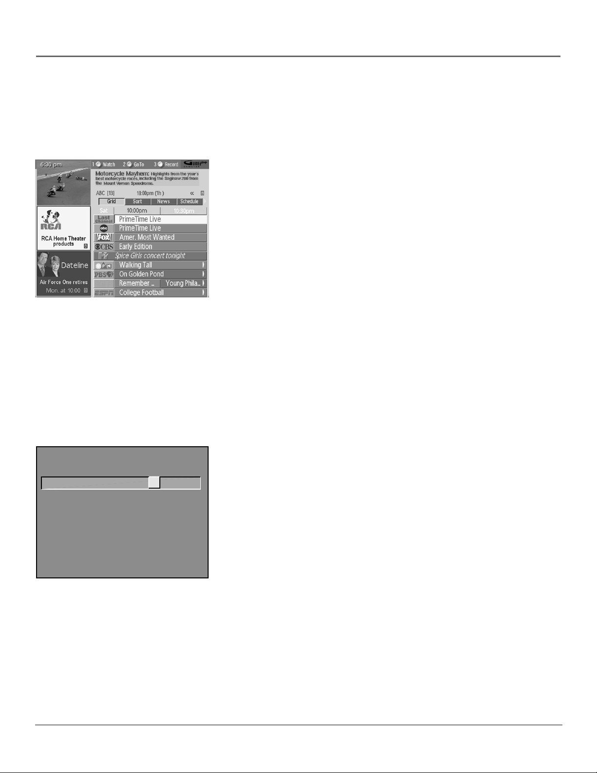
On-screen Program Guide
Description: The GUIDE Plus+ system is an on-screen interactive list of
programs and information that is built into your TV. You can scroll through the
guide to see what’s on and tune directly to that program from the guide. You
can also browse programs by category with the Sort feature.
When you access the News feature, MSNBC will appear in your video window if
available and display current news stories by headline.
One-Touch VCR Recording is another benefit of the GUIDE Plus+ system. You
don’t have to remember to program your VCR or use the menus in your VCR to
set up a recording.
Requirements:
• If there is a Demo Pin in the G-LINK jack on the back of the TV, remove it.
V-CHIP TV RATING LIMIT
Rating Status
TV-14 View
Press ^/v to view programs with
this content for this rating.
- - Content - -
DLSVFV
V V VV
^
• Complete the on-screen interactive setup. You’ll find detailed instructions in
Chapter 1.
• One-Touch VCR Recording: You must connect the G-LINK cable to the TV
and place one of the wands in front of the remote sensor on the VCR.
• If you have a cable box, connect the G-LINK cable to the TV and place one
of the wands in front of the remote sensor on the cable box.
V-Chip: Parental Controls
Description: You can block programs and movies by content, age-based
ratings, and/or movie ratings.
Requirements:
• Set up the Parental Controls menu in the TV’s main menu (Chapter 3
has details).
• The broadcasters must use the rating system when they send the program
to your TV in order for your TV to block the program.
• Parental controls must be locked for these settings to take affect.
1
Page 4
HIGH RESOLUTION
INPUT
AUDIO INPUTS
L
R
COMPONENT VIDEO INPUT
AUDIO
R
BPR
YP
16:9 Mode
Description: Lets you select a widescreen format for a wider viewing area
using a 16:9 aspect-ratio source, such as a DVD player, for display on this 4:3
aspect-ratio TV.
Requirements:
• A 16:9 aspect-ratio source, such as a DVD player or HD receiver.
• A 16:9 aspect-ratio disc or signal.
• The 16:9 source needs to be set to output a 16:9 format signal.
• The 16:9 mode on the TV needs to be on.
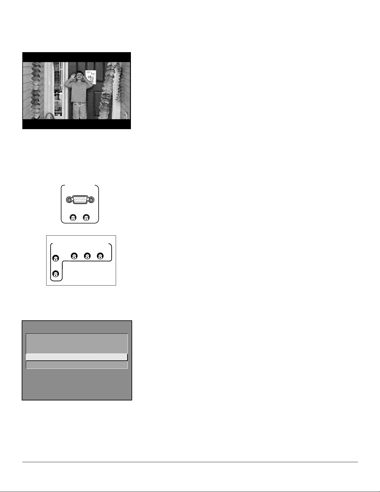
High Resolution Input and Component Video Input Jacks
Description: The HIGH RESOLUTION INPUT jack allows you to connect your
TV to an RGB device or component video device (Y•Pb•Pr) (with the supplied
adapter cable). The component video inputs can be used to connect a
component video device directly.
L
CHANNEL
1 Signal Type...
2
Auto Channel Search...
3 List and Labels...
4 Autotuning...
0 Go Back
Autotuning
Description: Allows you to set up the TV to automatically tune to a specific
channel when you press a certain component button on the remote (VCR1,
DVD, etc.).
Requirement: Set up Autotuning in the TV’s menu system. (Chapter 3
has details).
2
Page 5

Table of Contents
Introduction
Key Features Overview .................................................................................................... 1
On-screen Program Guide ......................................................................................... 1
V-Chip: Parental Controls...........................................................................................1
16:9 Mode ................................................................................................................... 2
High Resolution Input and Component Video Input Jacks...................................... 2
Autotuning ................................................................................................................. 2
Chapter 1: Connections & Setup
Things to Consider Before You Connect .........................................................................6
Protect Against Power Surges ................................................................................... 6
Protect Components from Overheating ................................................................... 6
Position Cables Properly to Avoid Audio Interference ............................................ 6
Important Stand and Base Safety Information ........................................................ 6
Use Indirect Light ....................................................................................................... 6
Demo Pin .................................................................................................................... 6
Choose Your Connection .................................................................................................. 7
Cables Needed to Connect Components to Your TV ...............................................7
How to Connect: TV + HD Receiver + VCR + DVD Player ......................................... 8
How to Connect: TV + Satellite Receiver + VCR .....................................................10
How to Connect: TV + DVD + VCR ..........................................................................11
How to Connect: A/V Receiver + Speakers.............................................................. 12
Explanation of Input Jacks and Cables ......................................................................... 13
Why You Should Connect the G-LINK Cable ................................................................. 15
How to Find the Remote Sensor ............................................................................. 15
Placing the G-LINK Wands ....................................................................................... 15
The Front of Your TV ...................................................................................................... 16
Front Inputs .............................................................................................................. 16
Front Panel ............................................................................................................... 16
Plug in the TV ........................................................................................................... 17
Place batteries in the remote .................................................................................. 17
Turn on the TV .......................................................................................................... 17
Complete the Interactive Setup..................................................................................... 18
Set the Menu Language .......................................................................................... 18
Complete Auto Channel Search .............................................................................. 18
The GUIDE Plus+ System Setup ................................................................................ 19
What to Expect ............................................................................................................... 23
Next Steps....................................................................................................................... 23
Chapter 2: Using the Remote Control
The Buttons on the Remote Control .............................................................................26
Using the INPUT Button ...........................................................................................27
Programming the Remote to Operate Other Components ......................................... 28
Find Out If You Need to Program the Remote ....................................................... 28
Programming the Remote ....................................................................................... 28
How to Use the Remote After You’ve Programmed It ..........................................30
3
Page 6

Table of Contents
Chapter 3: Using the TV’s Features
About the GUIDE Plus+ System..................................................................................... 34
Downloading Data ................................................................................................... 34
Getting In & Out of the GUIDE Plus+ System ......................................................... 35
The GUIDE Plus+ System Menus .............................................................................. 35
Grid Guide ................................................................................................................ 35
Sort ............................................................................................................................37
News .......................................................................................................................... 38
Schedule .................................................................................................................... 38
Messages ................................................................................................................... 39
Editor ........................................................................................................................ 40
Setup ......................................................................................................................... 40
How to Get More Information About an Advertisement or a Program ............... 41
GUIDE Plus+ Menu Items ............................................................................................... 41
Channel Banner .............................................................................................................. 42
Why You Should Use the Autotuning Feature ............................................................. 43
How to Set Up the Autotuning Feature ................................................................. 43
Parental Controls and V-Chip ......................................................................................... 45
How V-Chip Works ................................................................................................... 45
V-Chip TV Rating Limit ............................................................................................. 46
Blocking Specific Content Themes .......................................................................... 48
Viewing Specific Content Themes ...........................................................................49
V-Chip Movie Rating Limit ....................................................................................... 50
V-Chip Unrated Program Block ............................................................................... 51
Channel Block ........................................................................................................... 51
Front Panel Block ..................................................................................................... 51
Lock/Unlock Parental Controls ................................................................................ 51
PIP (Picture-in-Picture) Operation ..................................................................................52
PIP Buttons ................................................................................................................ 52
Tips for Using the PIP Buttons ................................................................................. 52
Chapter 4: Using the TV’s Menu System
How to Use Your TV’s Menu System............................................................................. 54
Audio Menu .................................................................................................................... 54
Picture Quality Menu ..................................................................................................... 55
Screen Menu ................................................................................................................... 56
Using Closed Captioning................................................................................................57
Channel Menu................................................................................................................. 58
Time Menu ...................................................................................................................... 58
Chapter 5: Other Information
Troubleshooting.............................................................................................................. 60
RCA HDTV Monitor Specifications................................................................................. 63
Care and Cleaning .......................................................................................................... 64
RCA HDTV Monitor Limited Warranty ..........................................................................65
Index................................................................................................................................74
4
Page 7

Chapter 1
Connections & Setup
Chapter Overview:
• Things to Consider Before You Connect
• Choose Your Connection
• Connections
• Explanation of Input Jacks and Cables
• Why You Should Connect the G-LINK Cable
• The Front of Your TV
• Plug in the TV
• Put Batteries in the Remote
• How to Use the Remote Control to Complete the Interactive
Setup
• Turn on the TV
• Complete the Interactive Setup
Changing Entertainment. Again.
Illustrations contained in this document are for representation only. 5
Page 8

Connections & Setup
Things to Consider Before You Connect
Protect Against Power Surges
• Connect all components before you plug any of their power cords into the wall outlet.
• Turn off the TV and/or component before you connect or disconnect any cables.
• Make sure all antennas and cables are properly grounded. Refer to the Important
Safeguards sheet packed with your TV.
Protect Components from Overheating
• Don’t block ventilation holes on any of the components. Arrange the components so that
air can circulate freely.
• Don’t stack components.
• When you place components in a stand, make sure you allow adequate ventilation.
• If you connect an audio receiver or amplifier, place it on the top shelf so the heated air
from it won’t flow around other components.
Position Cables Properly to Avoid Audio Interference
• Insert each cable firmly into the designated jack.
• If you place components above the TV, route all cables down the side of the back of the
TV instead of straight down the middle of the TV.
• If your antenna uses 300-ohm twin lead cables, do not coil the cables. Also, keep the twin
lead cables away from audio/video cables.
Important Stand and Base Safety Information
Choose the location for your TV carefully. Place the TV on a stand or base that is of adequate
size and strength to prevent the TV from being accidentally tipped over, pushed off, or pulled
off. This could cause personal injury and/or damage the TV. Refer to the Important Safeguards
sheet packed with your TV.
Use Indirect Light
Don’t place the TV where sunlight or room lighting will be directed toward the screen. Use soft
or indirect lighting.
N
I
P
O
M
E
D
s
e
t
a
v
i
t
c
a
n
i
P
o
m
e
D
s
i
c
h
i
T
t
a
m
o
t
u
a
n
a
.
o
m
e
d
+
s
u
l
P
E
D
I
U
G
;
S
R
E
L
I
A
T
E
R
s
i
h
t
e
v
o
m
e
r
T
l
O
l
i
N
w
o
l
D
a
v
o
m
e
R
.
.
n
o
i
P
m
e
o
d
m
c
e
i
t
D
a
m
o
t
u
a
e
h
t
e
l
b
a
s
i
d
:
S
R
E
M
U
S
N
O
n
i
C
P
o
m
e
D
s
i
h
t
e
E
l
V
b
O
a
c
M
k
E
n
R
i
L
-
G
e
h
t
t
.
r
V
e
T
s
s
n
i
i
h
t
d
n
g
a
n
i
s
u
e
r
o
f
e
b
e
r
e
h
Demo Pin
If there is a demo pin in the G-LINK jack on the back of the TV, you must
remove it before you connect the G-LINK cable. If there is no demo pin,
just insert the G-LINK cable into the G-LINK jack.
6 Chapter 1
Page 9
Connections & Setup
Choose Your Connection
There are several ways to connect your TV. Please use the following chart to determine which
connection is best for you. Proceed to the appropriate page and connect your TV.
Components Cables Connection Go to...
Needed Title
Coaxial
Audio/video
TV
TV
TV
D
H
eceiver
R
Satellite
DVD
DVD
C
V
VCR
R
C
V
R
G-LINK cable
RGB cable
Coaxial
Audio/video
G-LINK cable
Coaxial
Audio/video
G-LINK cable
Cables Needed to Connect Components to Your TV
TV + HD Receiver
+ DVD + VCR
TV + Satellite
Receiver + VCR
TV + DVD + VCR
page 8
page 10
pages 11
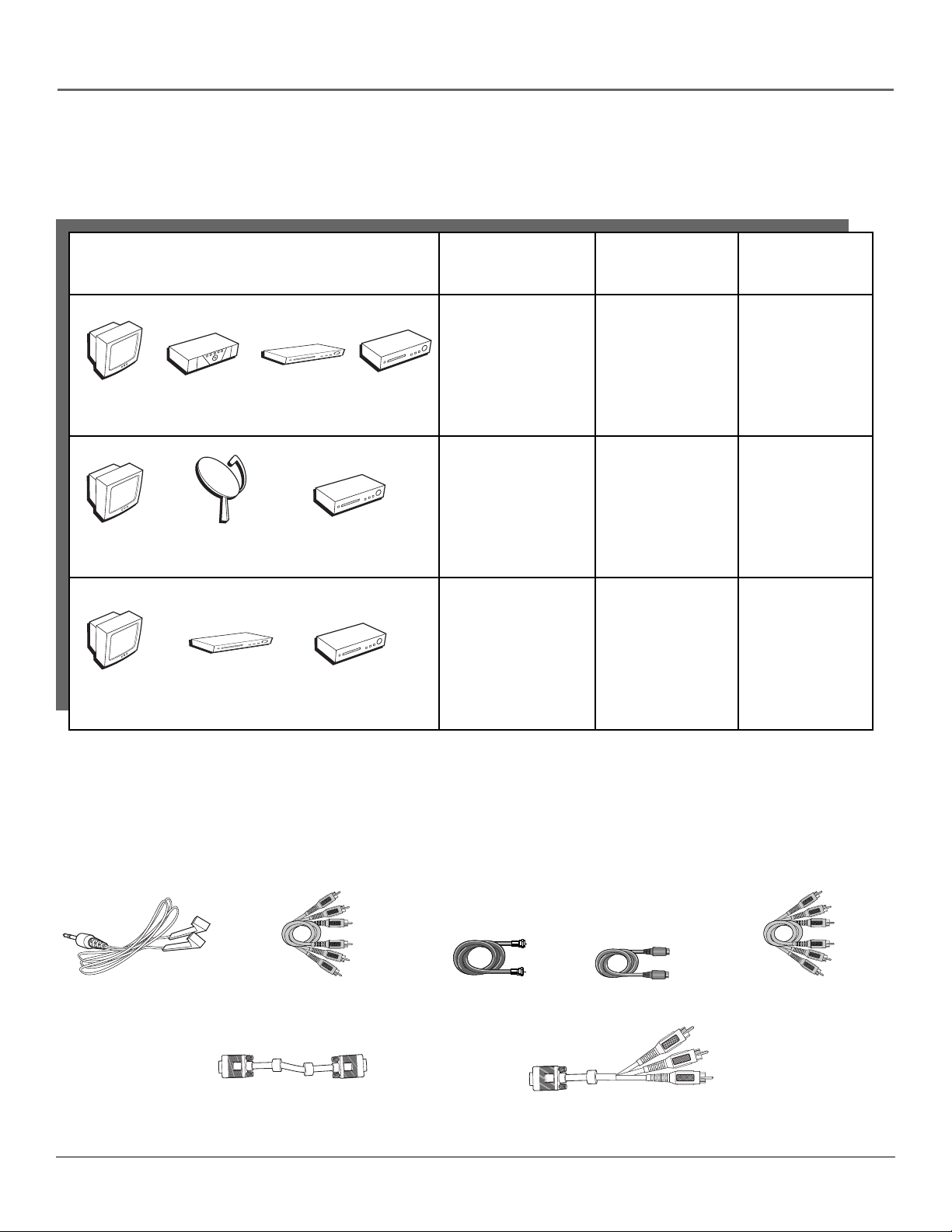
The pictures below show the cables needed for the connections represented in this book.
Note: Please locate the G-LINK cable (provided) when you’re getting ready to set up your TV. You need to connect this
cable to your TV and to your VCR and/or cable box in order for all of the features of the program guide to work
properly.
G-LINK cable
Audio/Video cables
High Resolution (RGB to RGB) cable
Coaxial cable
S-Video cable
High Resolution to Component Video
adapter (RGB to Y•Pb•Pr) cable
Component Video
(Y•Pb•Pr) cables
Chapter 1 7
Page 10
Connections & Setup
CABLE
OR
OFF-AIR ANTENNA
TV
HD
Receiver
VCR
AUDIO
VIDEO
L
IN
OUT
R
AUDIO
VIDEO
L
R
ANTENNA IN
ANTENNA OUT
2B
2A
3
ANTENNA/
CABLE INPUT
INPUT1
INPUT2
INPUT3
AUDIO
VIDEO
L
R
POWER
S-VIDEO
COMPONENT VIDEO INPUT
AUDIO
R
L
DVD
4B
DVD PLAYER
1
S-VIDEO
AUDIO
VIDEO
L
R
HD RECEIVER
VCR
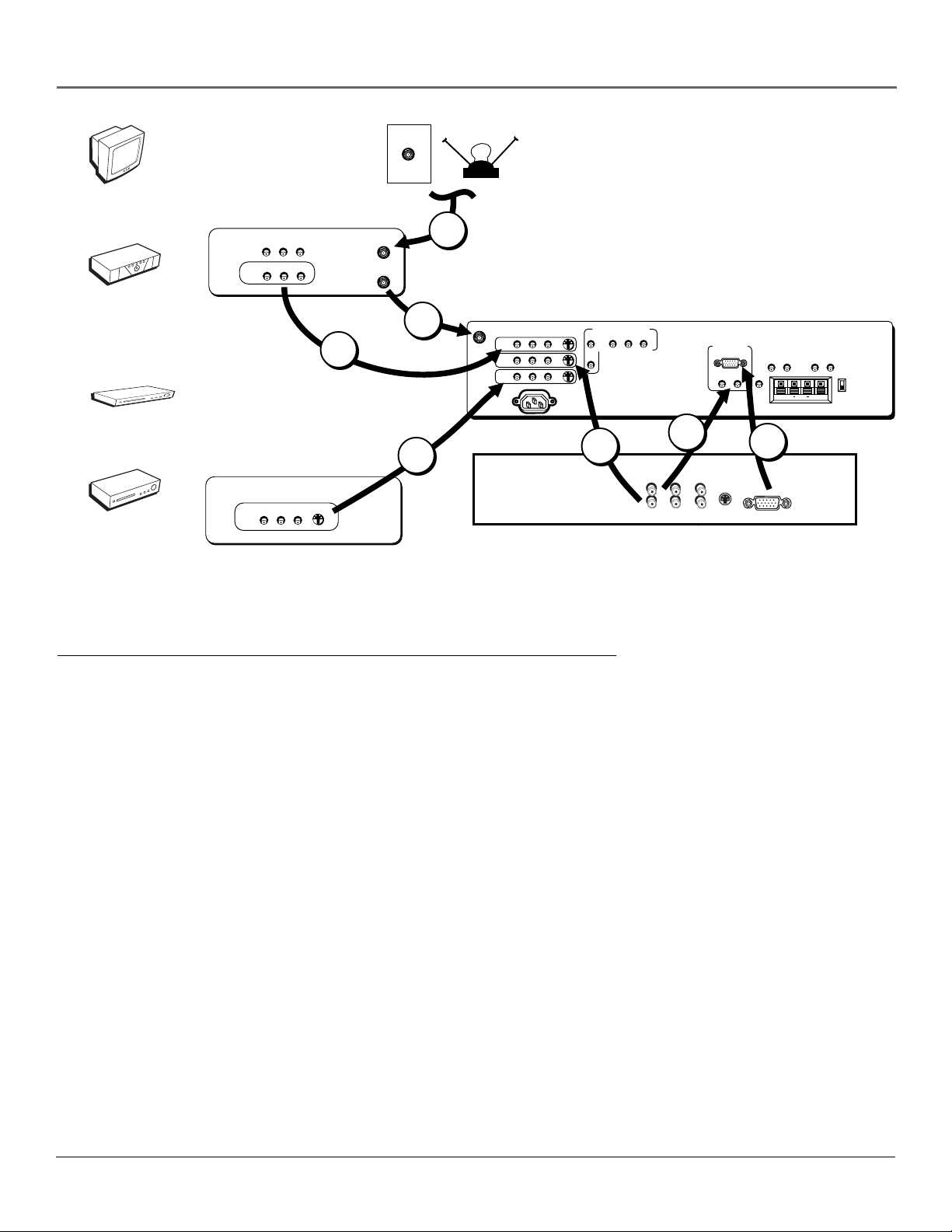
How to Connect: TV + HD Receiver + VCR + DVD Player
YP
BPR
RRL
AUDIO
L
4C
VIDEO
HIGH RESOLUTION
INPUT
AUDIO INPUTS
L
R
FIXED
LR L
G-LINK
4A
AUDIO OUTPUTS
EXT SPEAKERS
R
HDTV MONITOR
VARIABLE
R
EXT
INT
++
L
1. Connect your DVD Player to your TV.
A. Connect the DVD player’s audio/video output to INPUT3 on the TV using audio/video cables. If your DVD player
has an S-Video output, you can make the video connection by using the S-Video jacks instead.
Notes:
• If you are using an S-Video cable, you must also use audio cables. The S-Video cable only transfers video
information.
• If your DVD player has a component video output, we recommend you use the component video input on the TV
instead of the standard video or S-Video connection.
2. Connect your VCR to your TV.
A. Connect a coaxial cable to the VCR’s antenna output and to the ANTENNA/CABLE INPUT jack on the TV.
B. Connect the VCR’s audio/video output to INPUT1 on the TV using audio/video cables.
3. Make sure cable or antenna is connected to your VCR.
A. Connect the coaxial cable carrying your television signal (off-air or cable) to the antenna input on the VCR.
8 Chapter 1
Page 11

Connections & Setup
4. Connect your HD Receiver to your TV.
A. Connect the supplied high resolution cable to your HD receiver and to the HIGH RESOLUTION INPUT on the TV.
Note: Due to copyright restrictions, you may not be able to view some high definition programs in high definition
format using this product. To view material in standard definition instead, you also must connect the Audio/Video jacks
to the TV.
B. Connect audio/video cables from the HD receiver’s AUDIO OUT (R and L) and VIDEO jacks to the INPUT2 AUDIO
and VIDEO IN jacks on the TV.
C. Connect audio cables from the HD receiver’s AUDIO OUT (R and L) jacks to the TV’s HIGH RESOLUTION AUDIO IN
(R and L) jacks.
D. Connect an optional S-Video cable from the HD receiver’s S-VIDEO jack to the TV’s S-VIDEO jack.
Note: If you are using an S-Video cable, you must also use audio cables. The S-Video cable only transfers video
information.
Viewing the Components
1. Turn on the TV and the component(s) you want to view.
2. Press the TV button on the remote control.
3. Press the INPUT button on the remote control to scroll through the video inputs.
• The VCR can be viewed on the VID1 input channel.
• The HD receiver can be viewed on the HiRes (recommended) or VID2 input channel.
• The DVD player can be viewed on the VID3 input channel.
Notes:
• You can set up the TV to automatically tune to the correct input channel. This is called Autotuning. (See Chapter 3
for more information.)
• The TV automatically detects when a component is connected to the HIGH RESOLUTION INPUT jack. To connect a
component video device to this jack, you need to use the supplied RGB-component video adapter cable. The TV
automatically detects and displays the component video signal.
Important: If your RCA or PROSCAN HD receiver switches from a high definition output to a standard definition
output, you will need to switch from the high resolution input channel to the standard definition INPUT2 (VID2)
channel in order for you to view the signal. There are two situations in which this would occur:
• When recording from the HD receiver
• When a high definition output signal is not allowed by the program provider and/or movie studio for that
particular program
Go to page 15
Chapter 1 9
Page 12
Connections & Setup
TV
VCR
AUDIO
VIDEO
L
IN
OUT
R
AUDIO
VIDEO
L
R
ANTENNA IN
ANTENNA OUT
CABLE
OR
OFF-AIR ANTENNA
2
S-VIDEO
COMPONENT VIDEO INPUT
AUDIO
R
L
YP
BPR
HIGH RESOLUTION
INPUT
AUDIO INPUTS
L
R
FIXED
LR L
G-LINK
AUDIO OUTPUTS
EXT SPEAKERS
R
HDTV MONITOR
VARIABLE
++
L
Satellite
SATELLITE
RECEIVER
AUDIO
VIDEO
1B
S-VIDEO
AUDIO
VIDEO
L
OUT
R
1A
ANTENNA/
CABLE INPUT
INPUT1
INPUT2
INPUT3
L
R
POWER
3
VCR
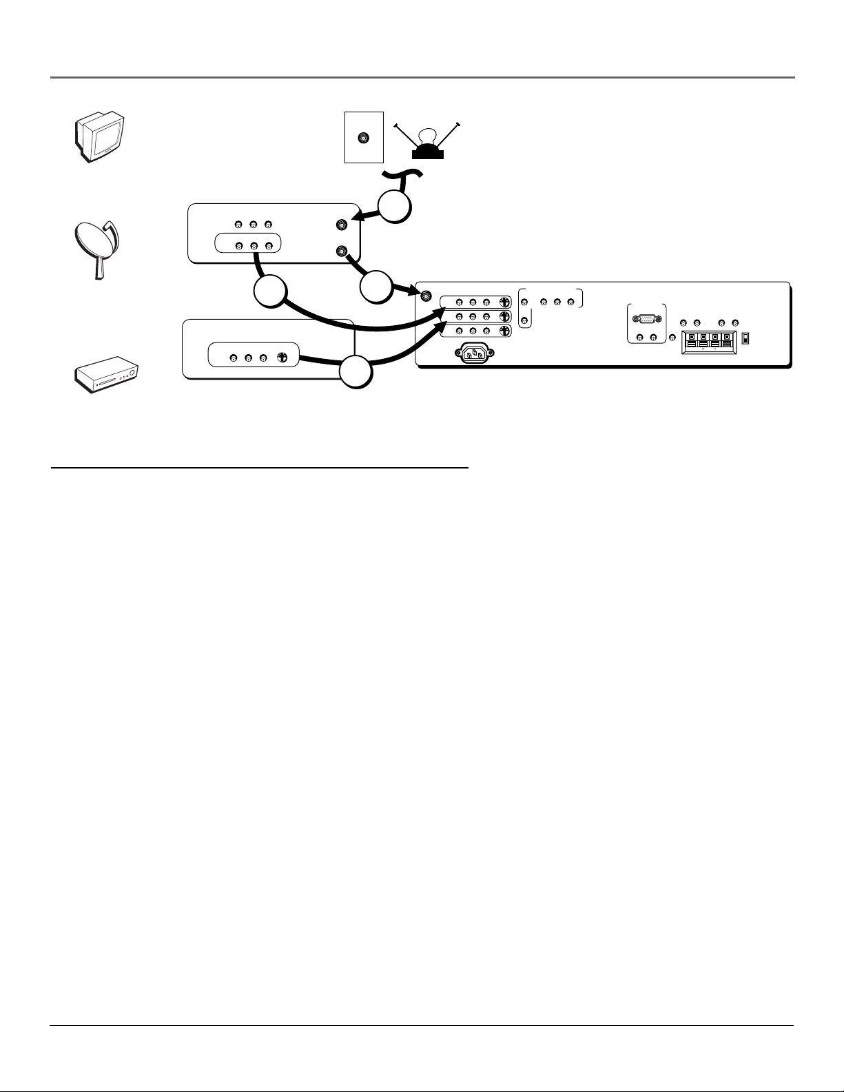
How to Connect: TV + Satellite Receiver + VCR
1. Connect your VCR to your TV.
A. Connect a coaxial cable to the VCR’s antenna output and to the ANTENNA/CABLE INPUT jack on the TV.
B. Connect the VCR’s audio/video output jacks to the INPUT1 AUDIO (R and L) and VIDEO jacks on the TV using
audio/video cables.
2. Make sure cable or antenna is connected to your VCR.
A. Connect the coaxial cable carrying your television signal (off air or cable) to the antenna input on the VCR.
3. Connect your Satellite Receiver to your TV.
A. Connect the satellite receiver’s audio/video output jacks to the INPUT2 AUDIO (R and L) and VIDEO jacks on the TV
using audio/video cables. If your satellite receiver has an S-Video output, you can make the video connection by
using the S-Video jacks instead.
R
EXT
INT
Note: If you are using an S-Video cable, you must also use audio cables. The S-Video cable only transfers video
information.
Viewing the Components
1. Turn on the TV and the component(s) you want to view.
2. Press the TV button on the remote control.
3. Press the INPUT button on the remote control to scroll through the video inputs.
• The VCR can be viewed on the VID1 input channel.
• The satellite receiver can be viewed on the VID2 input channel.
Note: You can set up the TV to automatically tune to the correct input channel. This is called Autotuning. (See Chapter
3 for more information.)
Go to page 15
10 Chapter 1
Page 13
TV
VCR
Connections & Setup
OR
CABLE
AUDIO
VIDEO
L
IN
OUT
R
AUDIO
VIDEO
L
R
ANTENNA IN
ANTENNA OUT
OFF-AIR ANTENNA
3
DVD
DVD PLAYER
2A
ANTENNA/
2B
S-VIDEO
AUDIO
VIDEO
L
R
1
CABLE INPUT
INPUT1
INPUT2
INPUT3
AUDIO
VIDEO
L
R
POWER
S-VIDEO
COMPONENT VIDEO INPUT
AUDIO
R
L
YP
BPR
HIGH RESOLUTION
INPUT
AUDIO INPUTS
L
R
FIXED
LR L
G-LINK
AUDIO OUTPUTS
EXT SPEAKERS
R
VCR
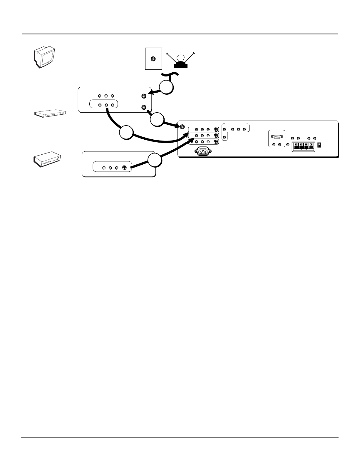
How to Connect: TV + DVD + VCR
1. Connect your DVD Player to your TV.
A. Connect the DVD player’s audio/video output jacks to the INPUT2 AUDIO (R and L) and VIDEO jacks on the TV
using audio/video cables. If your DVD player has an S-Video output, you can make the video connection by using
the S-Video jacks instead.
Notes:
• If you are using an S-Video cable, you must also use audio cables. The S-Video cable only transfers video
information.
• If your DVD player has a component video output, we recommend you use the component video input on the TV
instead of the standard video or S-Video connection.
2. Connect your VCR to your TV.
HDTV MONITOR
VARIABLE
R
EXT
INT
++
L
A. Connect a coaxial cable to the VCR’s antenna output and to the ANTENNA/CABLE INPUT jack on the TV.
B. Connect the VCR’s audio/video output jacks to the INPUT1 AUDIO (R and L) and VIDEO jacks on the TV using
audio/video cables.
3. Make sure cable or antenna is connected to your VCR.
A. Connect the coaxial cable carrying your television signal (off air or cable) to the antenna input on the VCR.
Viewing the Components
1. Turn on the TV and the component(s) you want to view.
2. Press the TV button on the remote control.
3. Press the INPUT button on the remote control to scroll through the video inputs.
• The VCR can be viewed on the VID1 input channel.
• The DVD player can be viewed on the VID3 input channel.
Note: You can set up the TV to automatically tune to the correct input channel. This is called Autotuning. (See Chapter
3 for more information.)
Go to page 15
Chapter 1 11
Page 14
Connections & Setup
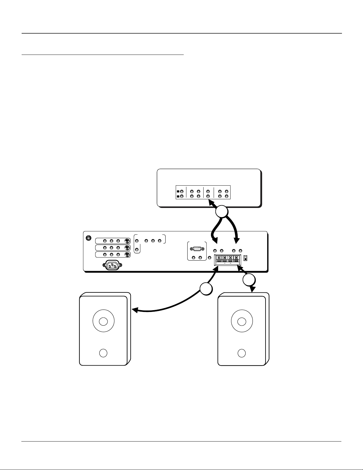
How to Connect: A/V Receiver + Speakers
1. Connect either the FIXED or VARIABLE AUDIO OUTPUT from the TV to an A/V receiver using audio cables.
• FIXED provides fixed-level audio output from the TV. This audio output is ideal for connecting to an A/V
receiver that has its own volume control.
Note: If you use the fixed audio output jacks, you may want to turn off the volume display in the Audio menu.
• VARIABLE provides variable-level audio output. Volume levels are controlled by the volume controls on the TV
and TV remote control.
2. Use speaker wire to connect the TV to external speakers.
• The EXT/INT switch beside the jacks let you turn the TV’s internal speakers on or off. EXT sends audio to
external speakers only. INT sends audio to the TV’s internal speakers only.
Note: The external speaker rating is 8 ohms with 10 watts power handling capabilities.
A/V RECEIVER
TAPE
CD
IN
L
R
TV
IN OUT IN
IN
VCR
OUT
ANTENNA/
CABLE INPUT
VIDEO
INPUT1
INPUT2
INPUT3
POWER
Right Speaker
1
Connect to either FIXED
or VARIABLE Output
S-VIDEO
COMPONENT VIDEO INPUT
AUDIO
R
L
YP
BPR
HIGH RESOLUTION
INPUT
AUDIO INPUTS
L
R
FIXED
LR L
G-LINK
AUDIO OUTPUTS
EXT SPEAKERS
R
VARIABLE
L
R
EXT
INT
++
AUDIO
L
R
2
2
Left Speaker
12 Chapter 1
Page 15
Connections & Setup
Explanation of Input Jacks and Cables
This section describes the jacks and cables you can use to make connections. There are several ways to connect
components to your TV.
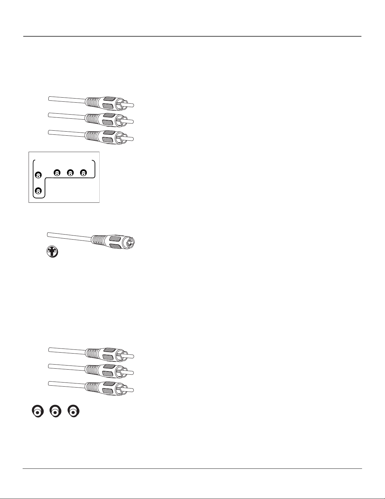
Component Video (Y•Pb•Pr) Jacks and Cables
The Y•Pb•Pr jacks allow you to connect an optional component video source,
such as a DVD player. This connection provides optimum picture quality
because the video is separated into three signals. To ensure maximum picture
quality, use three video-grade cables for the connection.
Note: Also, remember to connect the left and right audio cables because
the Y•Pb•Pr cables carry only the picture signal, not the sound.
COMPONENT VIDEO INPUT
AUDIO
R
L
BPR
YP
S-Video Jack
S-Video Jacks and Cables
The S-Video (separate video) jacks provide better picture quality than the
regular video jacks (labeled INPUT1 VIDEO; INPUT2 VIDEO; INPUT3 VIDEO)
because the color (chrominance, also called chroma) part of the signal is
separated from the black and white (luminance) part of the picture.
If a component you’re connecting to your TV (like a DVD) has an S-VIDEO
jack, connect the DVD to the TV with an S-Video cable (not provided) for a
better quality picture.
Note: Remember to connect the left and right audio cables because the
S-Video cable carries only the picture signal, not the sound.
Audio/Video Jacks and Cables (RCA-type)
These jacks are used for most audio/video connections between components.
The audio/video jacks are often color coded (yellow for video, red for right
audio, and white for left audio). This is also called composite video.
Note: If your component has only one input for audio (mono), connect it
to the left (white L/Mono) audio jack on the TV and don’t connect the
right audio part of the cable.
Audio/Video Jacks
Chapter 1 13
Page 16
Connections & Setup
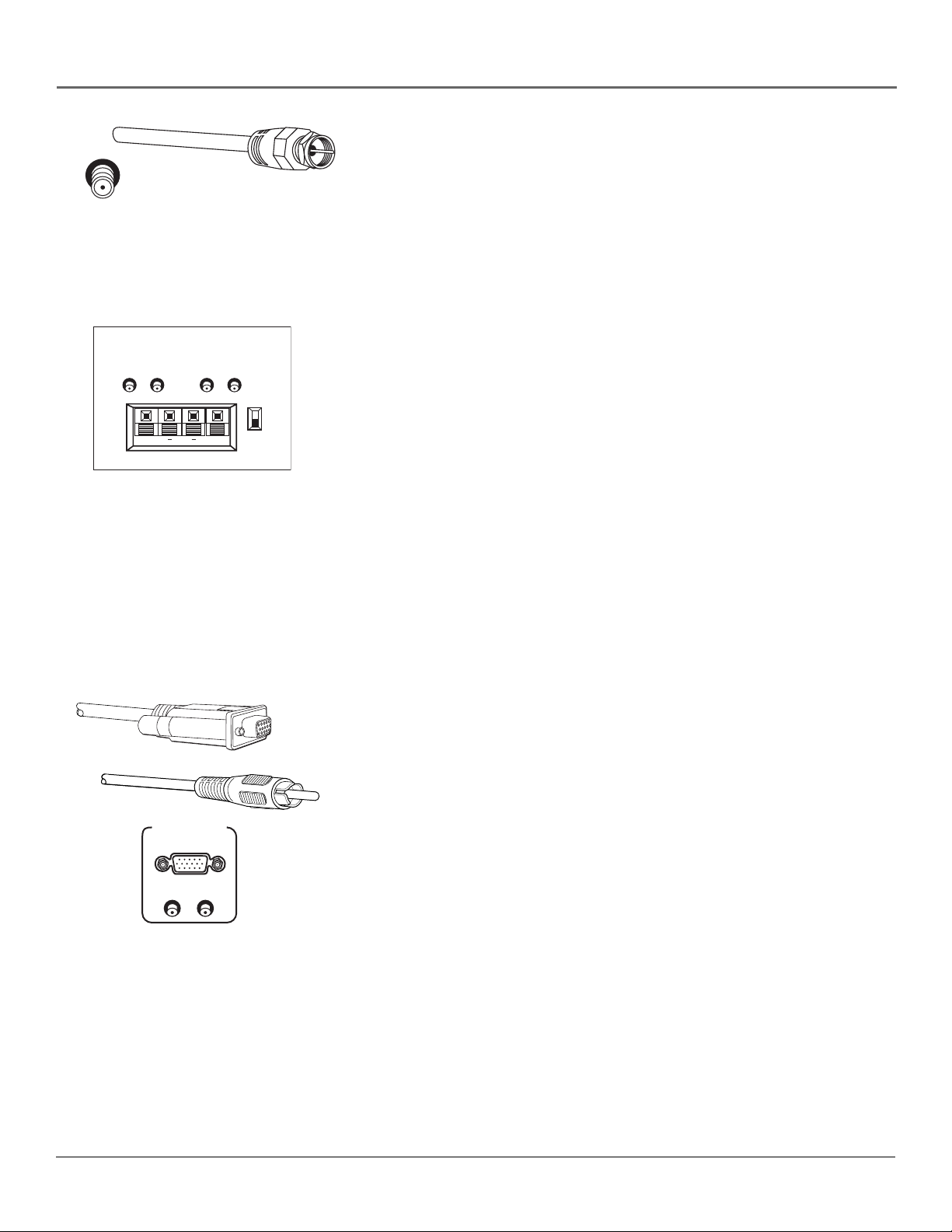
RF Jack and Coaxial Cables (F-type)
The RF jack is necessary for reception of off-air broadcasts, cable, and satellite
signals.
RF Jack
FIXED
LR L
AUDIO OUTPUTS
EXT SPEAKERS
VARIABLE
R
L
This jack is required for antenna or cable connections. The RF jack on the TV is
labeled ANTENNA/CABLE INPUT.
An RG-6 coaxial cable is required for all satellite signal distribution.
Audio Output Jacks and the External Speakers Jacks and Switch
These jacks are used to connect your TV to an audio receiver or other audio
R
EXT
processing component. The two types of jacks you can use for audio output are
fixed and variable. You can also connect external speakers directly to the TV, if
you want to use the TV’s audio processor.
INT
++
The FIXED jacks provide fixed-level audio output from the TV. This audio
output is ideal for connecting to an A/V receiver when you want to control the
volume through the A/V receiver.
Note: If you use the FIXED AUDIO output jacks, you may want to turn off
the volume display in the Audio menu.
The VARIABLE jacks provide variable-level audio output. Volume levels are
controlled by the volume controls on the TV and remote control.
The EXT SPEAKERS jacks let you connect external left and right speakers to the
TV. The EXT/INT switch beside the jacks lets you turn the TV’s internal
speakers on or off. EXT sends audio to external speakers only. INT sends audio
to the TV’s internal speakers only.
High Resolution Input Jack and Cables
This jack lets you connect your TV to an RGB or component video device
(Y•Pb•Pr). How images are displayed, however, depends on other factors such
as the type of device connected to the TV and the media being transmitted.
HIGH RESOLUTION
INPUT
Notes:
• Remember to connect the left and right audio cables because the
AUDIO INPUTS
L
R
high resolution cable carries only the picture signal, not the sound.
• The TV automatically detects when a component is connected to the
HIGH RESOLUTION INPUT jack. To connect a component video device
to this jack, you need to use the supplied RGB-component video
adapter cable. The TV automatically detects and displays the
component video signal.
14 Chapter 1
Page 17
Connections & Setup
Why You Should Connect the G-LINK Cable
The G-LINK cable enables the GUIDE Plus+ system (the on-screen interactive program guide) to
work with your VCR and/or cable box.
Cable Box – If your TV is connected to a cable box, you must connect the G-LINK cable to
receive TV program listings for your area and to tune directly to a channel when the program
guide is on your TV screen.
VCR – If your TV is connected to a VCR and you don’t connect the G-LINK cable, one-touch VCR
recording won’t work. The other features of the guide will work properly, however.
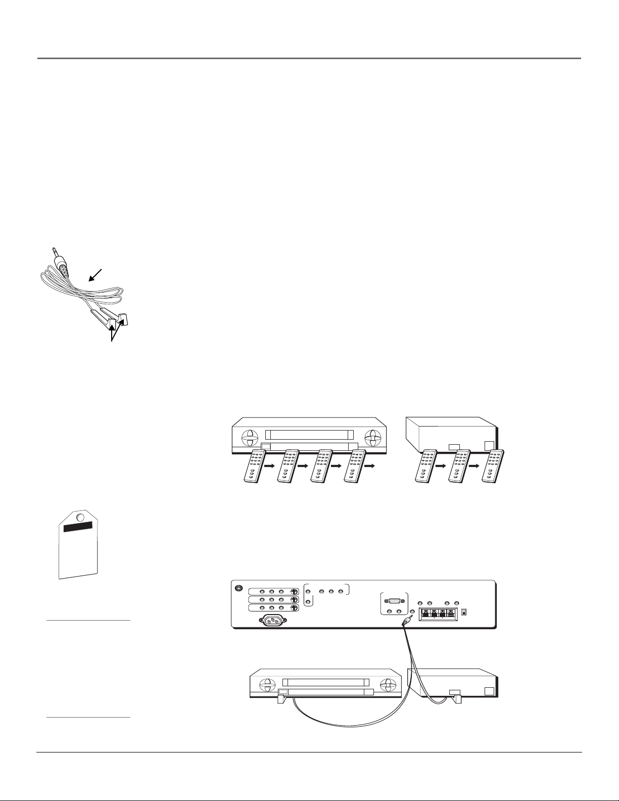
How to Find the Remote Sensor
G-LINK cable
G-LINK wands
If there is a demo
pin in the G-LINK
jack on the back of
the TV, you must
remove it before
you connect the GLINK cable. If there
is no demo pin,
just insert the
G-LINK cable into
the G-LINK jack.
N
I
P
O
M
E
D
s
e
t
a
v
i
t
c
a
n
i
P
o
m
e
D
s
i
c
h
i
T
t
a
m
o
t
u
a
n
a
.
o
m
e
d
+
s
u
l
P
E
D
I
U
G
;
S
R
E
L
I
A
T
E
R
s
i
h
t
e
v
o
m
e
r
T
l
O
l
i
N
w
o
l
D
a
v
o
m
e
R
.
.
n
o
i
P
m
e
o
d
m
c
e
i
t
D
a
m
o
t
u
a
e
h
t
e
l
b
a
s
i
d
:
S
R
E
M
U
S
N
O
n
i
C
P
o
m
e
D
s
i
h
t
e
E
l
V
b
O
a
c
M
k
E
n
R
i
L
-
G
e
h
t
t
.
r
V
e
T
s
s
n
i
i
h
t
d
n
g
a
n
i
s
u
e
r
o
f
e
b
e
r
e
h
Tip
If you don’t have both a
cable box and a VCR
connected to your TV,
just coil the cable of the
extra G-LINK wand with
a twist tie and leave it
behind the TV.
You have to place the G-LINK wands in front of the remote sensor on the VCR and/or cable box.
Some cable boxes and VCRs have the remote sensor labeled on the unit. If the remote sensor
isn’t labeled on your VCR and/or cable box, you need to use the remote control that came with
the VCR and/or cable box to locate the sensor.
1. Turn off the VCR and/or cable box.
2. Hold the remote control (not the one that came with your TV, but the one that came with
the cable box and/or VCR to which you’re attaching the G-LINK cable) so that it is touching
the front of the component.
3. Slowly move the remote control across the front of the component (VCR or cable box) while
you press the power button on and off. You must press and release the power button each
time you move the remote (holding down the button won’t work).
VCR
CABLE BOX
CHANNEL
03
4. When the component turns on, you’ve located the VCR’s or cable box’s remote sensor.
Placing the G-LINK Wands
Place the G-LINK wands in front of the remote sensor on your VCR and/or cable box
approximately one inch away from the remote sensor (see instructions below).
ANTENNA/
CABLE INPUT
VIDEO
INPUT1
INPUT2
INPUT3
POWER
TV (back panel)
AUDIO
L
R
Connect to G-LINK jack
on the back of the TV.
SENSOR
COMPONENT VIDEO INPUT
AUDIO
S-VIDEO
BPR
YP
R
L
HIGH RESOLUTION
INPUT
AUDIO INPUTS
L
VCR
R
LR L
G-LINK
FIXED
AUDIO OUTPUTS
EXT SPEAKERS
R
HDTV MONITOR
VARIABLE
R
EXT
INT
++
L
SENSOR
CHANNEL
03
Chapter 1 15
Page 18
Connections & Setup
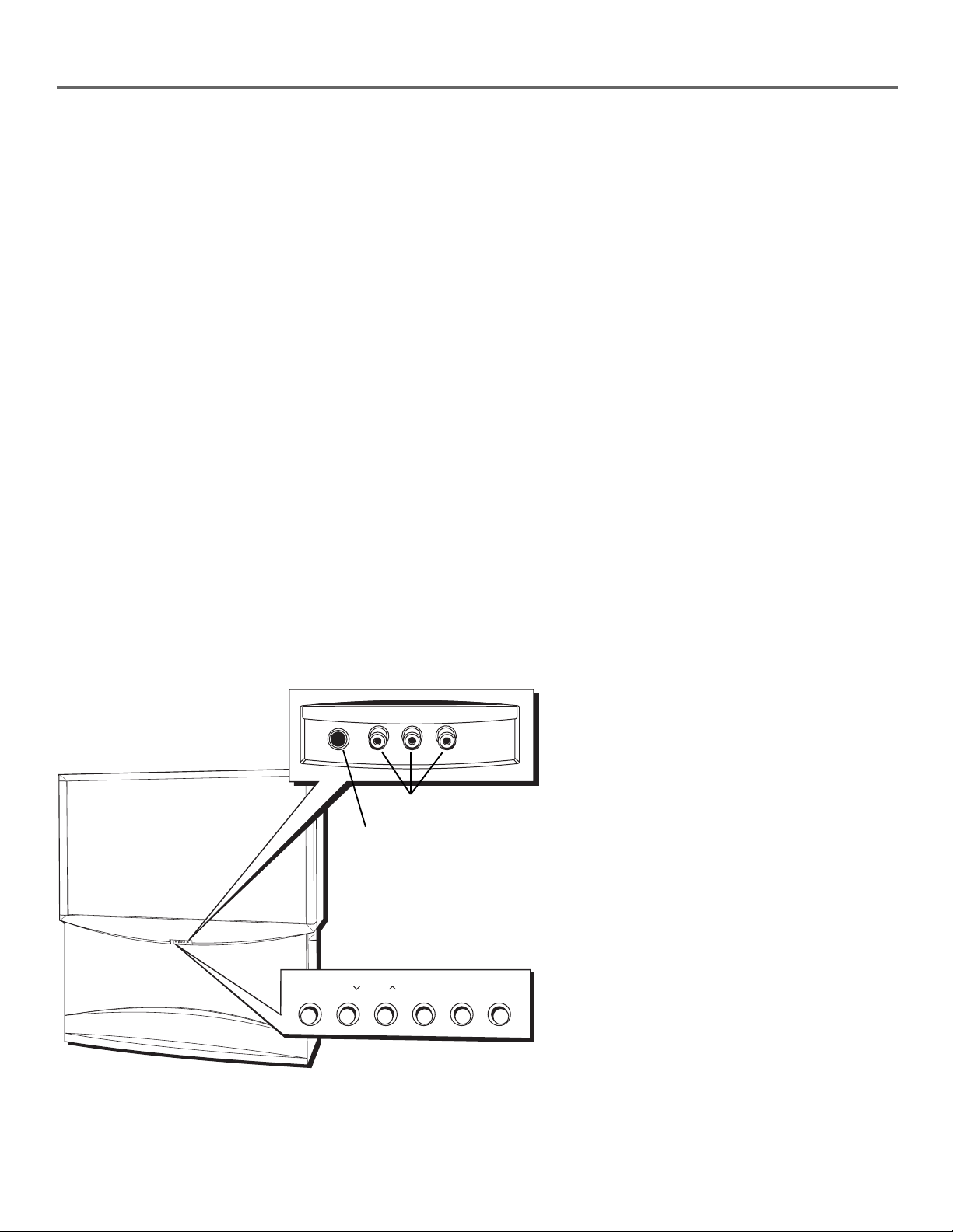
The Front of Your TV
Front Inputs
The TV has front inputs for convenience: one set of audio/video inputs, and a headphone jack. Look for a hinged door and
open the cover. Please note the illustration below shows a typical front input layout.
Notes:
• When you plug in headphones, the TV’s internal and external speakers are automatically turned off.
• When connecting a device that uses a monaural cable, such as some camcorders, use the Left (mono) input jack to
get sound from both speakers.
Front Panel
If you cannot locate your remote, you can use the front panel of your TV to operate many of the TV’s features.
MENU/OK Brings up the Main menu. In the menu system, it selects highlighted items.
CH v Scans down through the current channel list. In the menu system, it points down to items and adjusts menu controls.
CH ^ Scans up through the channel list. In the menu system, it points up to items and adjusts menu controls.
VOL - Decreases the volume. In the menu system, it points left to items and adjusts menu controls.
VOL + Increases the volume. In the menu system, it points right to items and adjusts menu controls.
POWER Turns the TV on and off.
The front panel illustration shows a
typical front panel layout. The exact look
may be different from the one on the
front of your TV.
If you use the Front Panel Block feature,
the front panel no longer provides
A/V jacks
Headphone jack
R
E
W
O
P
+
L
O
V
—
L
O
V
H
C
H
C
U
N
E
M
S
V
I
D
E
O
V
I
D
E
O
L
/
M
O
N
O
R
H
E
A
D
P
H
O
N
E
I
N
P
U
T
4
A
U
D
I
O
MENU
CH CH VOL — VOL + POWER
•OK
access to the menus. The Front Panel
Block feature disables all front panel
buttons. For more information, see
Chapter 3.
16 Chapter 1
Page 19
Connections & Setup
Plug in the TV
Plug the flat end of the cable into the POWER jack on the back of the
TV. Then plug the end of the power cord into an appropriate wall outlet.
Be sure to insert the plug completely.
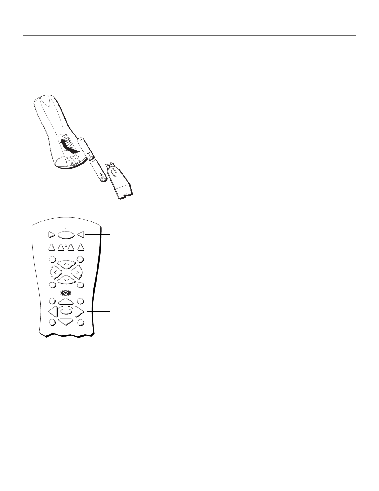
Put batteries in the remote
• Remove the battery compartment cover from the back of the remote
by pushing down on and sliding off the cover.
• Insert 2 “AA” fresh batteries. Make sure the polarities (+ and -) are
aligned correctly.
• Replace the cover.
How to Use the Remote Control to
Complete the Interactive Setup
VCR1
DVD
L
O
V
FETCH
GUIDE
MENU
VCR2
ON OFF
C
C
OK
The technical term is “Navigation” – how you move through the on-
TV
AUX
SAT•CABLE
SKIPMUTE
+
H
V
O
L
TV button
screen menus. The theory is the same throughout the menu screens:
highlight your choice and select it.
To highlight a menu item, press the arrow buttons on the remote to
highlight one of the items listed on the screen. Use the up or down
arrow button to move up or down. Use the right or left arrow button to
move right or left.
To select the item that you’ve highlighted, press OK.
H
-
GO BACK
INFO
Note: Highlighted means that the menu item stands out from
other menu items on the list (appears darker, brighter, or a
different color).
Arrows
CLEAR
Turn on the TV
Press TV on the remote, or press POWER on the TV’s front panel.
Note: Pressing the TV button not only turns on the TV, but puts
the remote into TV mode. “TV mode” means that the buttons on
the remote control operate the TV’s functions.
Chapter 1 17
Page 20

Connections & Setup
Complete the Interactive Setup
Tip
To access the setup menus
manually, press MENU and choose
SETUP.
SETUP
Select the language to be used
in these menus.
1 English
2 Español
3 Français
SETUP
Would you like the monitor to
search for all available channels?
1 Yes
2 No, skip this step
The menu system in your TV allows the TV’s features to work properly.
In this book, we call it the “interactive setup” because the TV asks you
questions, you answer, and the TV makes the appropriate adjustments.
The first time you turn on your TV, the setup screens appear
automatically.
Set the Menu Language
The first part of the SETUP menu asks you to select your preferred
language for the menu system.
1. Highlight your preferred language for the menu system using the
arrow buttons.
2. Press OK to select that language.
Complete Auto Channel Search
The next part of the SETUP asks you if you want the TV to search for all
channels viewable through your antenna or cable TV system. This is
sometimes called “auto programming.”
1. Highlight Yes and press OK to tell the TV to begin searching for
channels. A progress report appears on the screen.
2. When the screen on the TV tells you the search is complete, press
OK (the first GUIDE Plus+ system setup screen appears).
Note: If you skip Auto Channel Search now, you can access it later
through the Channel menu. See Chapter 4 for more details.
18 Chapter 1
Page 21
Tip
If you move to a new zip or postal
code, or if any of your information
changes and you need to access the
setup screens from the TV’s main
menu— press MENU, choose GUIDE
Plus+ Menu, and choose GUIDE
Plus+ Setup, then choose Setup.
Connections & Setup
The GUIDE Plus+ System Setup
Important: If you have a VCR or cable box connected to the TV,
you need to connect the G-LINK cable to use the GUIDE Plus+
system. Go to page 15.
The GUIDE Plus+ system is an on-screen interactive program guide that
lists what shows are on TV in your area. In order to receive program
listings, you need to complete the following steps.
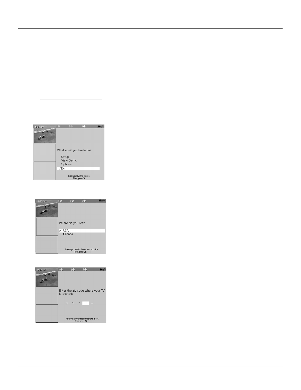
Step 1: Begin Setup
Use the arrow buttons to highlight Setup and press OK.
Step 2: Identifying Your TV’s Location
1. If your country is highlighted, press OK on the remote control.
If your country isn’t highlighted, press the up or down arrow button
on the remote control to highlight your country and press OK.
2. Use the number buttons on your remote to enter your zip code or
postal code.
Press OK when you’re finished.
Note: If your postal code contains letters, press the up and down
arrow buttons on your remote to enter letters, and press the right
arrow button to go to the next space. The left arrow button also
moves the highlight to the left.
Chapter 1 19
Page 22

Connections & Setup
Step 3: Configuring for Cable
The next series of screens asks you about your cable setup. To supply
your TV with the correct TV program listings, the GUIDE Plus+ system
needs to know if your TV is connected to cable.
1. If your TV is connected to cable, highlight Yes and press OK.
If your TV isn’t connected to cable, highlight No and press OK.
2. If you have a cable box connected to this TV, highlight Yes and press
OK on your remote control.
Note: The next series of screens is very important because the
GUIDE Plus+ system must find the correct cable box information in
order to receive the correct TV program listings.
If you don’t have a cable box connected to this TV, highlight No and
press OK. Then go to page 22.
3. Use the arrow buttons to highlight your brand of cable box, and
press OK.
If your brand isn’t listed, highlight Not Listed and press OK.
4. Make sure your cable box is on.
5. Tune the cable box to channel 02 (use the remote control that came
with your cable box, or press the channel buttons on the cable box).
Press OK (the GUIDE Plus+ system starts testing codes).
Important: When code testing is in progress, don’t touch your TV,
VCR, cable box, or any of the remote controls for these products.
20 Chapter 1
Page 23
Connections & Setup
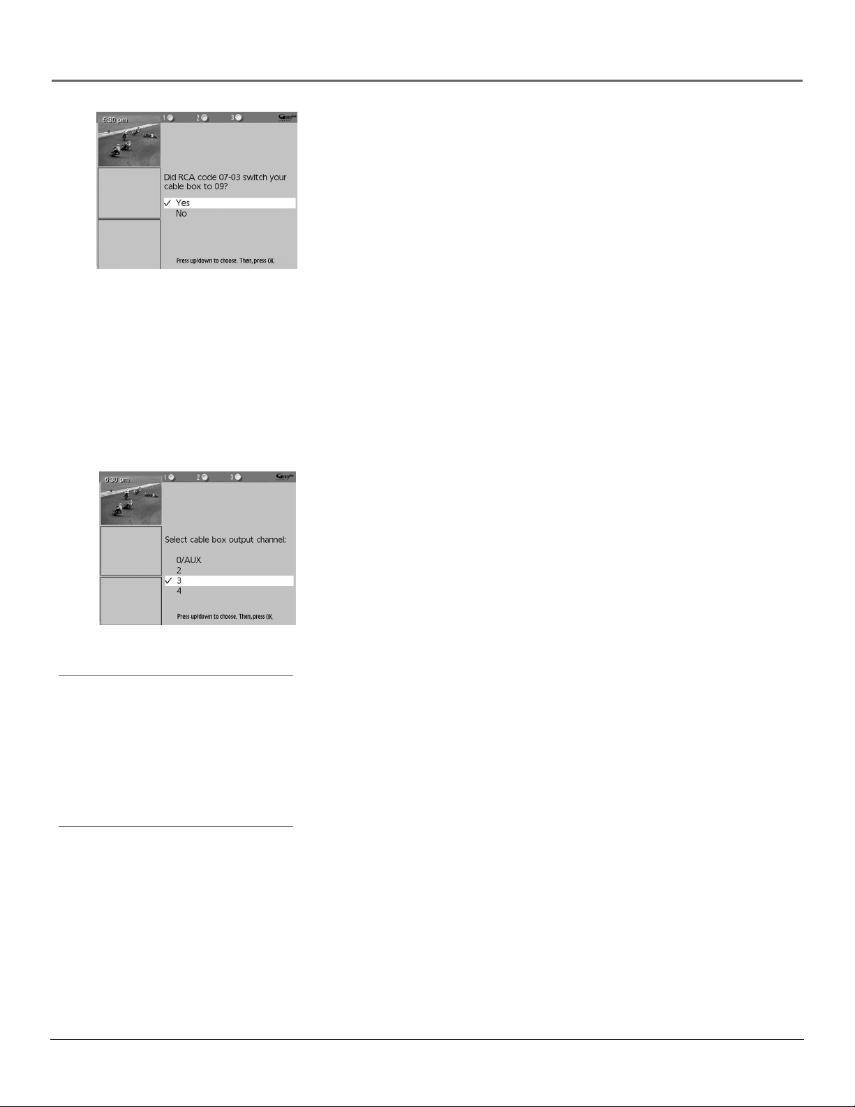
6. Look at your cable box. If it is still on and changed to channel 09,
the test was successful. Highlight Yes, and press OK.
If the cable box did not change to channel 9, highlight No. If you
select No, the system will try another code.
If the GUIDE Plus+ system cannot recognize your cable box after
several tries, a screen stating “Cable Box (VCR) test failed...Please
consult your manual and try again” appears. You have a choice to
either Try Again or Skip Cable Box Setup. If you get this message,
you should also:
• Double check the brand of your cable box, and try entering it
again.
• Check to make sure the G-LINK cable wand is positioned
correctly.
If you choose to skip the cable box or VCR setup some features of
the guide may not be available until you successfully complete this
procedure.
Tips
If you’re not sure which channel is the cable
box’s output channel, consult the owner’s
manual that came with your cable box or
contact your cable company.
Leave your cable box turned ON to receive
program information.
Leave your VCR turned OFF to record programs.
7. Highlight the channel to which you have to tune your TV in order to
see cable programming, and press OK (a screen appears reminding
you to connect your G-LINK cable to your TV and cable box).
Notes:
• Channel 03 is the most common.
• Choose Video1/AUX if your cable box is connected to your TV
with audio/video cables instead of a coaxial cable. Go to page
13 for pictures of these cables.
Chapter 1 21
Page 24
Connections & Setup
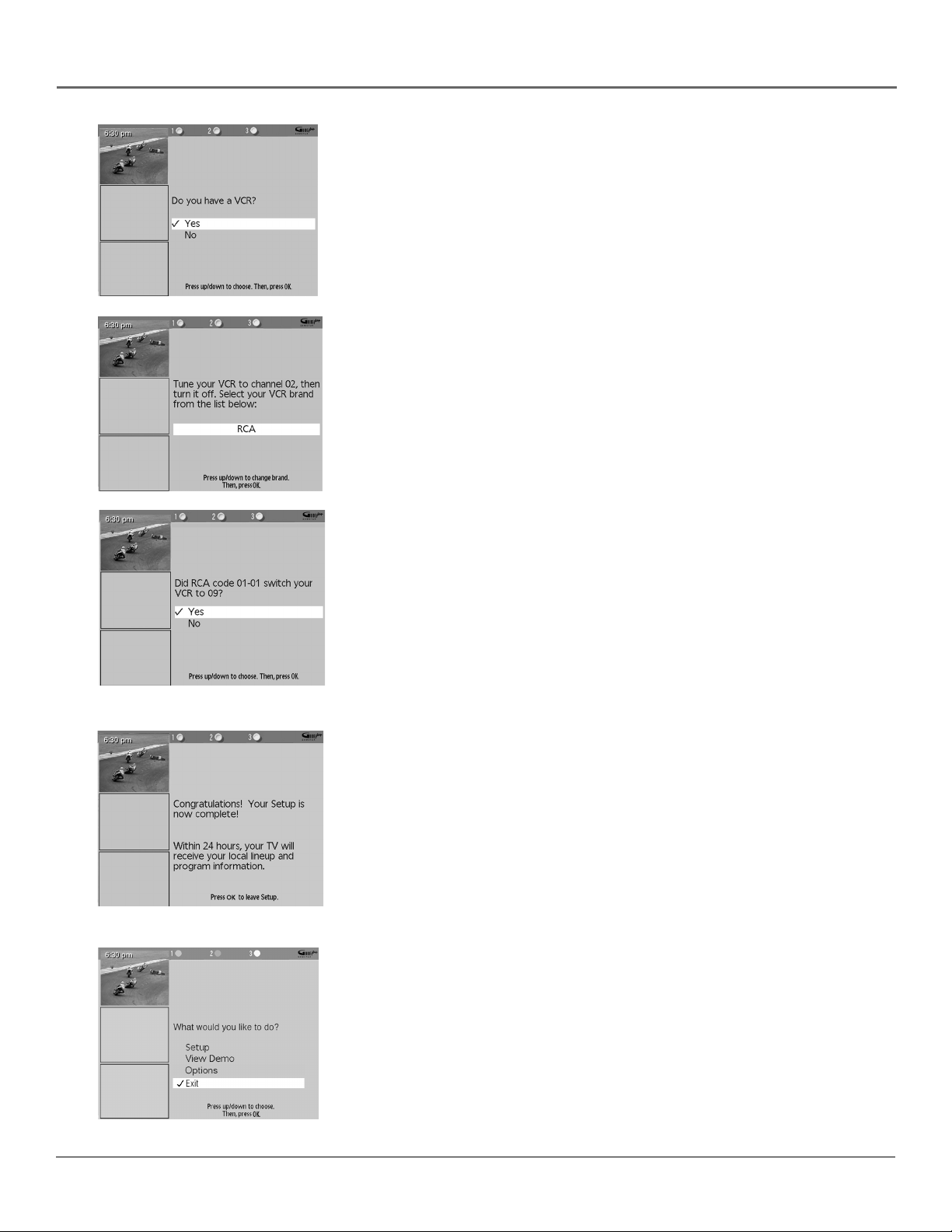
Step 4: Configuring for a VCR
1. If your TV is connected to a VCR, press OK.
If it is not, highlight No and press OK. (Answering No automatically
skips to the end of GUIDE Plus+ setup.)
2. Use the up and down arrow buttons to highlight the brand of your
VCR that is connected to the TV and press OK.
If your brand isn’t listed, highlight Not Listed and press OK.
3. Tune your VCR to channel 02. Next, turn OFF your VCR. When you
complete these steps, press OK to begin testing.
Important Note: When code testing is in progress, don’t touch
your TV, VCR, or any of the remote controls for these products.
4. Look at the front display of your VCR. If your VCR turned on
automatically and changed to channel 09, the test was successful.
Highlight Yes and press OK.
If your VCR did not change to channel 9, highlight No. If you select
No, the system will try another code.
If the GUIDE Plus+ system cannot recognize your VCR after several
tries, a screen stating “Cable Box (VCR) test failed...Please consult
your manual and try again” appears. You have a choice to either Try
Again or Skip VCR Setup. If you get this message, you should also:
• Double check the brand of your VCR, and try entering it again.
• Check to make sure the G-LINK cable wand is positioned
correctly.
If you choose to skip the cable box or VCR setup some features of
the guide may not be available until you successfully complete this
procedure.
You can choose to view a demo of the GUIDE Plus+ features, which
may take a few minutes to load. If you don’t want to see the demo
right now, highlight Exit and press OK to watch TV.
22 Chapter 1
Page 25

Connections & Setup
What to Expect
The next time you turn on your TV, the GUIDE Plus+ system will appear on the screen. The following examples explain
what you might see:
• If all of the program information has been sent to your TV, the GUIDE Plus+ system appears with all of your TV
program listings.
• If the program information hasn’t been sent to your TV yet, an outline of the GUIDE (without TV program listings) will
appear on the screen. Program information is usually sent to your TV at night.
• If more than one cable company services your area, you may be prompted with a Channel Mapping screen after the
first GUIDE Plus+ system download. You will need to identify your cable company by selecting the correct channel
numbers for the stations in question.
Features of the GUIDE Plus+ system are explained in Chapter 3.
To clear the guide from your screen, press CLEAR or GUIDE on the remote control.
Next Steps
Now that you’ve finished the Interactive Setup, you’re ready to watch TV. This might be a good time to program your
remote control. The remote control that came with this TV can be programmed to operate other components. Go to the
next chapter to find out how to program your remote.
Chapter 1 23
Page 26

This page left intentionally blank.
Page 27

Chapter 2
Using the Remote Control
Chapter Overview:
• The Buttons on the Remote Control
• Programming the Remote to Operate Other Components
• How To Use the Remote After You’ve Programmed It
• Code List
Changing Entertainment. Again.
Illustrations contained in this document are for representation only. 25
Page 28

Using the Remote Control
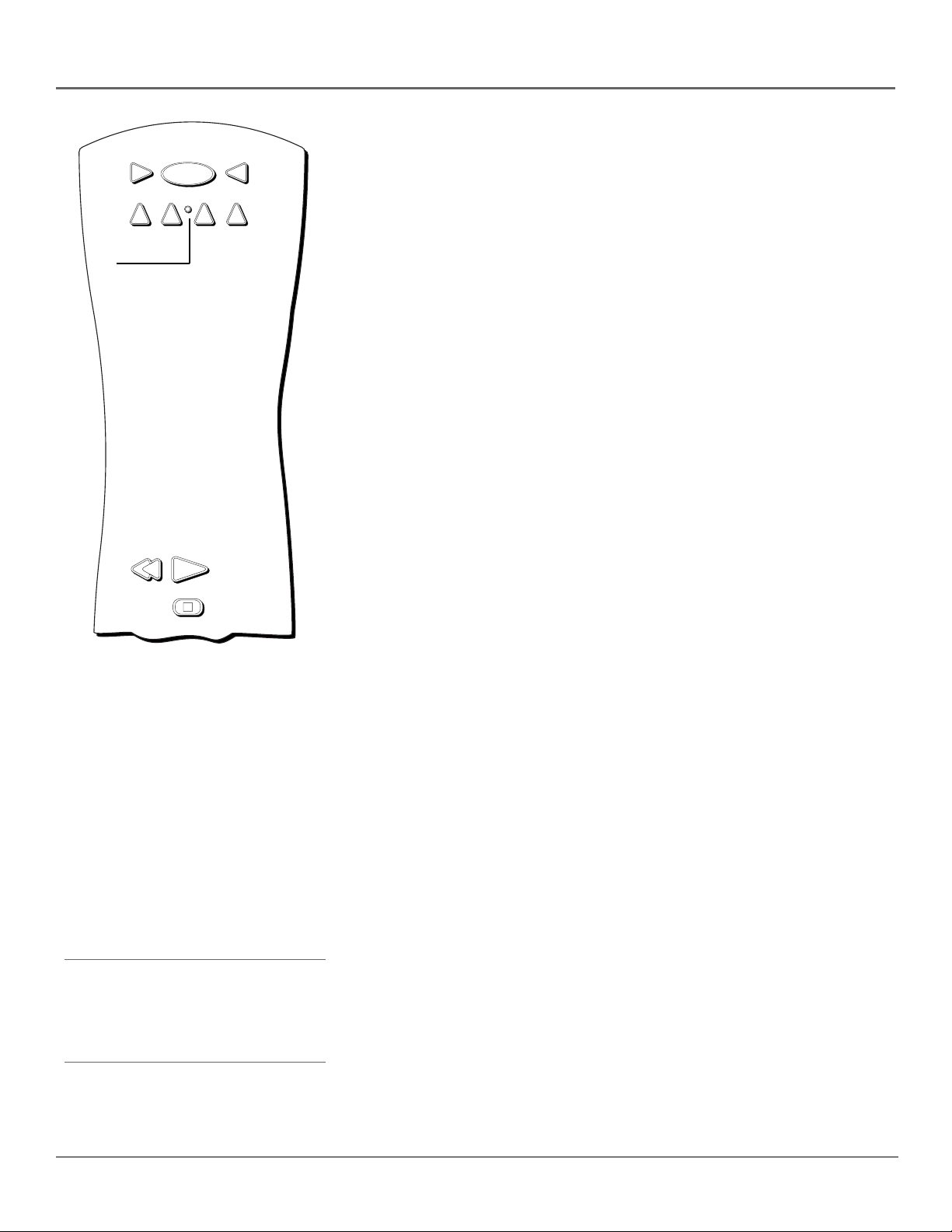
The Buttons on the Remote Control
VCR2
ON OFF
AUX
TV
SAT•CABLE
(0-9) Number Buttons Enter channel numbers and time settings
directly through the remote control. They are also used in the GUIDE
Plus+ system and in the TV menu to make selections.
VCR1
DVD
Indicator
SKIPMUTE
+
H
C
To enter a one-digit channel, enter a zero first. To enter a two-digit
channel, press the two digits. To enter a three-digit channel, press and
hold the “1” button until “1” and two dashes (– –) appear, then add the
L
O
V
V
O
L
second two digits. Example: to tune to channel 123, press and hold 1
until “1– –” appears, release the 1 button and then press 2 and 3.
ANTENNA Functions as TV/VCR button in VCR mode and TV/receiver
FETCH
GUIDE
H
GO BACK
INFO
button in satellite mode for most brands.
Move (Arrows) Used to point to different items in the GUIDE Plus+
C
-
system and TV menu and to adjust the menu controls. Also moves the
OK
PIP window when no menus are on the screen.
AUX Puts the remote in AUX mode. Can also be programmed to
operate most brands of an additional remote-controllable component.
MENU
2
1
4
7
5
8
INPUT
0
PLAY FORWARDREVERSE
3
6
9
ANTENNA
CLEAR
Backlight Lights up some of the buttons in the dark.
CH + or CH - Scans up or down through the current channel list. Press
once to change the channel up or down; press and hold to continue
changing channels. In DVD mode, skips chapters for some brands. In the
Guide Plus+ system, scrolls a page of info at a time.
CH CTRL When using PIP, selects the picture window, (that is, the
main or PIP window) to be changed by the CH ^ (channel up) or CH v
(channel down) buttons.
REC•VCR+
PIP
STOP PAUSE
CH CTRL
SWAP
WHO
Note: The VCR1, DVD, VCR2, and
SAT•CABLE buttons also turn on most
RCA, GE, and PROSCAN products.
CLEAR Removes any menu or display from the screen and returns you
to normal viewing.
DVD Puts the remote in DVD mode and, if Autotuning is enabled, will
turn on the TV and tune to the correct input channel.
FETCH Turns 16:9 mode on or off in the TV mode.
GO BACK Returns you to the previous channel or previous screen in
the menu system.
GUIDE Brings up and exits the GUIDE Plus+ system. In SAT•CABLE
mode, brings up available on-screen guides for some brands.
INDICATOR Indicates the programming mode when programming the
remote to control components.
INFO Brings up channel information; press again to clear the screen. In
the GUIDE Plus+ system, brings up more program information.
INPUT In TV mode, press to toggle through the available input sources
(VID1, VID2, VID3, FRONT, HiRes, CMPNT, last channel).
MENU Brings up the Main menu and selects highlighted items. In VCR
mode, it functions as a PROGRAM button for most brands.
26 Chapter 2
Page 29

Using the Remote Control
Tip
To turn off all the RCA, GE, and PROSCAN components
that are connected to the TV, press ON•OFF twice
within two seconds.
This feature only works with most RCA, GE, and
PROSCAN products.
MUTE Reduces the TV’s volume to its minimum level. Press again to
restore the volume.
OK When in the menu system, selects highlighted items.
ON•OFF When in TV mode, turns the TV on and off. If in another
device mode (VCR, DVD, SAT•CABLE, etc.) and programmed, will turn
the device on and off.
PIP Brings up the small picture-in-picture window. Press again to
remove the PIP window. (See Chapter 3 for more information about
using PIP.)
REVERSE, PLAY, FORWARD, REC•VCR+, STOP, PAUSE If
programmed, provides transport control for some remote-controllable
VCRs, DVD players, laserdisc players, tape decks, and CD players.
Pressing REC•VCR+ when using the GUIDE Plus+ System sets the VCR
to record a program.
SAT•CABLE Puts the remote in SAT•CABLE mode and, if Autotuning is
enabled, will turn on the TV and tune to the correct input channel.
SKIP Press once before changing channels and the TV will wait 30
seconds before returning you to the original channel. Press repeatedly to
add more time. Also, activates Search function for some GE, RCA, or
PROSCAN VCRs.
SWAP When using PIP, swaps the main picture with the PIP window.
TV Turns on the TV and puts the remote in TV mode. Also displays
channel information.
VCR1 Puts the remote in VCR1 mode and, if Autotuning is enabled,
will turn on the TV and tune to the correct input channel.
VCR2 Puts the remote in VCR2 mode and, if Autotuning is enabled,
will turn on the TV and tune to the correct input channel.
VOL – or VOL + Decreases or increases the TV’s volume.
WHO In SAT mode, press to select available channel lists “profiles”
(RCA, GE, and PROSCAN satellite or HD receivers only). This button
does not operate in the TV mode.
Using the INPUT Button
Use the INPUT button to scroll through the available input channels and
view components you have connected to the TV.
1. Press TV to place the remote in TV mode. Make sure the
component you want to view is turned ON.
2. Press INPUT to tune to an available input channel.
3. To return to the channel you were previously watching, press
the INPUT button until you see the channel in the upper right
corner.
Chapter 2 27
Page 30
Using the Remote Control
Indicator
VCR1
DVD
REVERSE
ON • OFF
VCR2
PLAY
STOP
AUX
TV
Programming the Remote to Operate Other Components
SAT•CABLE
The universal remote can be programmed to operate most brands of
remote controllable components. The remote is already programmed to
operate most RCA, GE, and PROSCAN components.
Also, the AUX button can be programmed to operate most brands of an
additional remote-controllable component.
Note: The TV button can’t be programmed on this remote.
Find Out If You Need to Program the Remote
To determine whether the universal remote needs to be programmed for
your component, turn the component ON. For example, to program the
remote for a VCR, turn on the VCR. Point the remote at the VCR, and
press the VCR1 button. Then press ON•OFF or CH + (channel up) or
CH – (channel down) to see if the VCR responds to the remote
commands. If the component does not respond, the remote needs to be
programmed.
Programming the Remote
There are two ways to program the remote control:
You ’ll use these buttons when
you program the remote.
Important: The remote may not
be compatible with all models of
all brands of components. It also
may not operate all functions of
the remote that came with your
component.
Tip
To stop the automatic code search without
programming any components, press and hold
CLEAR until the indicator on the remote turns
off.
• automatic code search
• direct entry
Using Automatic Code Search
The following instructions can be used to program the remote to operate
each of your components. If you want to stop the automatic code search
without programming any of your components, press CLEAR until the
indicator on the remote turns off.
Note: The AUX button can’t be programmed using automatic code
search. It must be programmed using the direct-entry method.
1. Turn on the component you want to operate (VCR, DVD player, etc.)
2. Press and hold the component button you want to program (VCR1,
DVD, etc.). While holding the component button, press and hold
ON•OFF until the indicator on the remote turns on, then release
both buttons.
3. Point the remote at the component. Press and release PLAY, then
wait 5 seconds or until the indicator on the remote stops flashing.
28 Chapter 2
Page 31

Using the Remote Control
At this point the remote is searching for the correct code to program.
If, after 5 seconds, the component you want to operate does not turn
off, press PLAY again to tell the remote to search the next set of
codes.
Continue pressing PLAY until the component turns off or you have
searched through all of the codes. There are 20 total sets of codes. If
the component does not turn off after pressing PLAY 20 times, then
the remote can’t be programmed to operate that component.
If the component you want to control does turn off:
1. Press and release REVERSE, then wait 2 seconds. Repeat this step
until the device turns back ON.
2. To finish, press and hold STOP until the indicator on the remote
turns off.
Important
You must continue pressing the component button
while you enter the code.
Let’s say you have a Zenith VCR. To program the
universal remote to operate the VCR, you would:
Press and hold the VCR1 button while you enter the
first code listed for Zenith in the VCR Codes column.
Release the VCR1 button. Press ON•OFF to see if the
VCR responds. If it doesn’t, follow the same steps, but
enter the second code for Zenith VCRs instead of the
first.
Note
The buttons might operate differently for other
components, especially when you’re using another
component’s menu system.
Using Direct Entry
1. Turn on the component to be programmed.
2. Look up the brand and code number(s) for the component on the
code list in this section.
3. Point the remote at the component.
4. Press and hold the component button you want to program on the
remote.
5. Enter the 4-digit code from the remote control code list on the
following pages. If the indicator flashes, you have either entered an
invalid code or the button isn’t programmable.
6. Release the component button, and then press ON•OFF to see if the
component responds to the command. If it doesn’t, try pressing the
component button and then ON•OFF again.
• If you get no response, repeat these steps using the next code listed
for your brand, until the component responds to the remote
commands.
• If you try all the codes for your component brand and none work,
try the automatic code search method. If automatic code search
doesn’t find the code, the remote is not compatible with your
component.
Chapter 2 29
Page 32

Using the Remote Control
How to Use the Remote After You’ve Programmed It
Because this universal remote can control several different components (TV, DVD, VCR, satellite receiver, etc.) it uses
operational modes triggered by the component buttons. For example, if you want the remote to control the TV, you would
press the TV button to put the remote into TV mode before you could control the TV.
1. Press the appropriate component button (DVD, TV, VCR1, VCR2, SAT•CABLE, AUX) to set the remote to control the
component.
2. Press ON•OFF to turn the component ON or OFF.
3. Use the remote buttons that apply to that component.
Notes:
• The remote may not be compatible with all brands and models of components. It also may not operate all functions
of the remote that came with your component.
• If you keep pressing buttons and nothing happens, the remote is probably in the wrong mode. You must press the
component button that matches the component you want to operate (i.e., if you want to operate the VCR, press
VCR1 on the remote control to put the remote in VCR mode.)
30 Chapter 2
Page 33

VCR Codes
Programmable for VCR1, VCR2, and
AUX buttons.
Admiral ........................................................ 2131
Adventura .................................................... 2026
Aiko ............................................................. 2027
Aiwa ................................................... 2002, 2026
Akai ..................... 2003, 2004, 2005, 2007, 2008,
................................................. 2111, 2112, 2113
American High ............................................ 2021
Asha ............................................................. 2013
Audio Dynamics ................................ 2009, 2010
Audiovox ..................................................... 2014
Bell & Howell ............................................. 2011
Beaumark .................................................... 2013
Broksonic .......................................... 2012, 2025
Calix ............................................................. 2014
Candle .......................... 2013, 2014, 2015, 2016,
................................................. 2017, 2018, 2019
Canon ...................................... 2021, 2022, 2114
Capehart ............................................ 2020, 2110
Carver .......................................................... 2062
CCE .................................................... 2027, 2061
Citizen ............................................... 2013, 2014,
................... 2015, 2016, 2017, 2018, 2019, 2027
Colortyme .................................................... 2009
Colt .............................................................. 2061
Craig .............................. 2013, 2014, 2023, 2061
Curtis-Mathes ................ 2000, 2002, 2009, 2013,
................... 2016, 2018, 2021, 2022, 2024, 2115
Cybernex ..................................................... 2013
Daewoo .............. 2015, 2017, 2019, 2025, 2026,
Daytron ........................................................ 2110
DBX ................................................... 2009, 2010
Dimensia ..................................................... 2000
Dynatech ........................................... 2002, 2026
Electrohome ...................................... 2014, 2029
Electrophonic .............................................. 2014
Emerson .... 2002, 2012, 2014, 2015, 2021, 2024,
......... 2026, 2029, 2030, 2032, 2033, 2034, 2035,
................... 2036, 2037, 2038, 2039, 2040, 2041,
.................. 2042, 2044, 2045, 2047, 2065, 2105
...................................... 2113, 2116, 2117, 2130
Fisher ...................................... 2011, 2023, 2048,
............................. 2049, 2050, 2051, 2052, 2118
Fuji ..................................................... 2021, 2119
Funai .................................................. 2002, 2026
Garrard ........................................................ 2026
GE ........................................... 2000, 2001, 2013,
............................. 2021, 2022, 2053, 2115, 2120
Goldstar ............... 2009, 2014, 2018, 2054, 2121
Gradiente ..................................................... 2026
Harley Davidson ......................................... 2026
Harman Kardon .......................................... 2009
Harwood ..................................................... 2061
Headquarter ................................................ 2011
Hitachi .................................... 2002, 2055, 2056,
............................. 2057, 2107, 2111, 2120, 2122
Hi-Q ............................................................. 2023
Instant Replay ............................................. 2021
JCL ............................................................... 2021
JC Penney ..................... 2009, 2010, 2011, 2013,
............................ 2014, 2021, 2022, 2055, 2056,
............................. 2058, 2059, 2060, 2107, 2118
Jensen ...................................... 2055, 2056, 2111
JVC ....2009, 2010, 2011, 2018, 2058, 2111, 2123
Kenwood ................................ 2009, 2010, 2011,
............................ 2016, 2018, 2058, 2111, 2123
KLH .............................................................. 2061
Kodak ................................................ 2014, 2021
Lloyd .................................................. 2002, 2026
Logik ............................................................ 2061
2027, 2028, 2110
2025,
Using the Remote Control
LXI .................................................................................. 2014
Magnavox ...................................................2021, 2022, 2062,
........................................................... 2063, 2104, 2108, 2124
Magnin ............................................................................ 2013
Marantz .......................................................2009, 2010, 2011,
...................................... 2016, 2018, 2021, 2058, 2062, 2064
Marta ............................................................................... 2014
Masushita ........................................................................ 2021
Mei .................................................................................. 2021
Memorex .................................................... 2002, 2011, 2013,
....................................... 2014, 2021, 2023, 2026, 2104, 2131
MGA ............................................................. 2029, 2065, 2113
MGN Technology ........................................................... 2013
Midland ........................................................................... 2053
Minolta ......................................................... 2055, 2056, 2107
Mitsubishi ........... 2029, 2055, 2056, 2065, 2066, 2067, 2069,
.................. 2070, 2071, 2072, 2073, 2074, 2106, 2113, 2123
Montgomery Ward ............................................... 2075, 2131
Motorola ............................................................... 2021, 2131
MTC ............................................................. 2002, 2013, 2026
Multitech ........................ 2002, 2013, 2016, 2026, 2053, 2061
NEC .......................................... 2009, 2010, 2011,2016, 2018,
............................. 2058, 2064, 2076, 2078, 2079, 2111, 2123
Nikko .............................................................................. 2014
Noblex ............................................................................ 2013
Olympus ......................................................................... 2021
Optimus ................................................................ 2014, 2131
Optonica ......................................................................... 2096
Orion .............................................................................. 2035
Panasonic ...................... 2021, 2022, 2109, 2125, 2126, 2127
Pentax ...................................... 2016, 2055, 2056, 2107, 2120
Pentex Research ............................................................. 2018
Philco ................................................. 2021, 2022, 2062, 2063
Philips ................................................2021, 2062, 2096, 2124
Pilot ................................................................................. 2014
Pioneer .................................... 2010, 2055, 2080, 2081, 2123
Portland ............................................. 2016, 2017, 2019, 2110
PROSCAN ............................................................. 2000, 2001
Protec .............................................................................. 2061
Pulsar .............................................................................. 2104
Quarter ........................................................................... 2011
Quartz ............................................................................. 2011
Quasar ......................................................... 2021, 2022, 2125
RCA ..................... 2000, 2001, 2003, 2013, 2021, 2055, 2056,
................. 2082, 2083, 2084, 2085, 2086, 2087, 2088, 2089,
....................................... 2090, 2091, 2107, 2115, 2120, 2125
Radioshack/Realistic .............. 2002, 2011, 2013, 2014, 2021,
................... 2022, 2023, 2026, 2029, 2049, 2050, 2096, 2131
Radix ............................................................................... 2014
Randex ............................................................................ 2014
Ricoh ............................................................................... 2128
Runco ............................................................................. 2104
Samsung ........................ 2005, 2013, 2015, 2033, 2053, 2112
Sanky .................................................................... 2104, 2131
Sansui ................................................ 2010, 2092, 2111, 2123
Sanyo ...........................................................2011, 2013, 2023
Scott ........................................ 2012, 2015, 2025, 2032, 2035,
Sears ....................................... 2011, 2014, 2021, 2023, 2048,
............................ 2049, 2050, 2051, 2055, 2056, 2107, 2118
Sharp .................... 2002, 2017, 2029, 2094, 2095, 2096, 2131
Shintom ............................................. 2004, 2056, 2061, 2098
Shogun ........................................................................... 2013
Signature ............................................................... 2002, 2131
Singer ........................................................... 2021, 2061, 2128
Sony ............................... 2002, 2004, 2098, 2099, 2119, 2128
STS ........................................................................ 2021, 2107
Sylvania ...................................................... 2002, 2021, 2022,
............................................... 2026, 2062, 2063, 2065, 2124
Symphonic ............................................................ 2002, 2026
Tandy .................................................................... 2002, 2011
Tashiko ........................................................................... 2014
Tatung ....................................................................2058, 2111
TEAC ........................................ 2002, 2026, 2058, 2085, 2111
Technics ................................................................ 2021, 2109
2038, 2065, 2093, 2116
Teknika ............... 2002, 2014, 2021, 2026, 2100, 2129
TMK .................................................. 2013, 2024, 2047
Toshiba ............................................ 2015, 2049, 2051,
............................................... 2055, 2065, 2093, 2116
Totevsion .................................................... 2013, 2014
Unitech ................................................................. 2013
Vector Research...................... 2009, 2010, 2015, 2016
Victor .................................................................... 2010
Video Concepts ............ 2009, 2010, 2015, 2016, 2113
Videosonic ............................................................ 2013
Wards ........................... 2002, 2013, 2014, 2015, 2021,
.......................... 2023, 2026, 2029, 2055, 2056, 2061,
................. 2096, 2101, 2102, 2103, 2107, 2116, 2131
XR-1000 ............................................ 2021, 2026, 2061
Yamaha ............... 2009, 2010, 2011, 2018, 2058, 2111
Zenith ........................... 2004, 2098, 2104, 2119, 2128
Cable Box Codes
Programmable for SAT•CABLE and
AUX buttons.
ABC ........... 5002, 5003, 5004, 5005, 5006, 5007, 5053
Antronix ...................................................... 5008, 5009
Archer ..................................... 5008, 5009, 5010, 5011
Cabletenna ........................................................... 5008
Cableview ............................................................. 5008
Century ................................................................. 5011
Citizen ................................................................... 5011
Colour Voice............................................... 5012, 5013
Comtronics ................................................. 5014, 5015
Contec .................................................................. 5016
Eastern .................................................................. 5017
Garrard ................................................................. 5011
GE Electronics ...................................................... 5009
Gemini .............................................. 5018, 5019, 5049
General Instrument .............................................. 5003
Hamlin .......................... 5020, 5021, 5022, 5035, 5045
Hitachi .................................................................. 5003
Hytex .................................................................... 5002
Jasco ..................................................................... 5011
Jerrold .................................... 5003, 5005, 5007, 5018,
................................................ 5023, 5024, 5046, 5053
Magnavox ............................................................. 5025
Memorex .............................................................. 5026
Movie Time ...................................... 5002, 5027, 5028
NSC ................................................... 5002, 5027, 5028
Oak ................................................... 5002, 5016, 5029
Panasonic .................................................. 5048, 5052
Paragon ................................................................ 5026
Philips .............................................. 5011, 5012, 5013,
...................................... 5019, 5025, 5030, 5031, 5032
Pioneer ....................................................... 5033, 5034
Pulsar .................................................................... 5026
RCA ................................................... 5047, 5049, 5052
Realistic ....................................................... 5009, 5049
Regal ........................................................... 5022, 5035
Regency ................................................................ 5017
Rembrandt ............................................................ 5003
Runco ................................................................... 5026
Samsung ..................................................... 5014, 5034
Scientific Atlanta ..................... 5006, 5036, 5037, 5038
Signal .......................................................... 5014, 5018
Signature ............................................................... 5003
Sl Marx .................................................................. 5014
Sprucer ................................................................. 5052
Starcom ............................................. 5007, 5018, 5053
Stargate ....................................................... 5014, 5018
Starquest ............................................................... 5018
Tandy .................................................................... 5040
Teleview ............................................................... 5014
Tocom ............................................... 5004, 5023, 5041
Toshiba ................................................................. 5026
Tusa ...................................................................... 5018
Chapter 2 31
Page 34

Using the Remote Control
TV86 ....................................................................... 5027
Unika .................................................. 5008, 5009, 5011
United Artists .......................................................... 5002
United Cable .......................................................... 5053
Universal ................................... 5008, 5009, 5010, 5011
Videoway ................................................................ 5044
Viewstar .................................... 5015, 5025, 5027, 5040
Zenith ................................................. 5026, 5050, 5051
Satellite Receiver Codes
Programmable for SAT•CABLE and AUX
buttons.
Alphastar ................................................................ 5079
Chapparal ..................................................... 5006, 5057
Dishnet ................................................................... 5078
Drake ............................................................ 5058, 5059
Echostar .................................................................. 5089
GE ....................................5000, 5001, 5071, 5080, 5081
General Instuments ............................ 5060, 5061, 5062
Hitachi .......................................................... 5083, 5084
Hughes ......................................................... 5077, 5090
JVC .......................................................................... 5082
Panasonic ............................................................... 5075
Phillips .................................................................... 5085
Primestar ................................................................. 5076
PROSCAN ........................ 5000, 5001, 5071, 5080, 5081
RCA ..................................5000, 5001, 5071, 5080, 5081
Realistic ................................................................... 5063
Sony ........................................................................ 5072
STS1 ........................................................................ 5064
STS2 ........................................................................ 5065
STS3 ........................................................................ 5066
STS4 ........................................................................ 5067
Toshiba ......................................................... 5068, 5073
Uniden .................................................................... 5086
DVD codes
Programmable for DVD and
AUX buttons.
Aiwa ........................................................................ 3009
Hitachi .................................................................... 3008
JVC ................................................................ 3002, 3010
Konka ........................................................... 3011, 3012
Magnavox ............................................................... 3003
Mitsubishi ............................................................... 3004
Panasonic ............................................................... 3013
Phillips .......................................................... 3019, 3021
Pioneer ................................................................... 3005
RCA ............................................................... 3000, 3001
Sanyo ...................................................................... 3014
Shinco ..................................................................... 3001
Sony .................................................... 3006, 3015, 3016
Toshiba ............................................... 3007, 3017, 3020
Zenith ..................................................................... 3018
Receivers
Aiwa ............................................... 4261, 4262, 4263, 4264,
......................................................... 4265, 4266, 4267, 4277
Denon ............................................................................ 4283
Harman Kardon ............................................................ 4276
JBL ................................................................................. 4276
JCV ................................................................................. 4268
Kenwood ............................................................. 4264, 4269
Onkyo ............................................................................ 4278
Optimus .........................................................................4284
Panasonic ............................................................ 4279, 4280
Pioneer .......................................................................... 4275
Sherwood ...................................................................... 4282
Sony ................................................. 4266, 4271, 4272, 4281
Technics ............................................................... 4279, 4280
Wards ............................................................................. 4275
Yamaha ................................................................ 4272, 4274
CD Players
ADC ........................................................... 4200, 4201, 4220
Aiwa ..................................................................... 4175, 4203
Akai ................................................................................ 4205
Denon ............................................................................ 4208
Dynatech ....................................................................... 4177
Emerson ......................................................................... 4178
Fisher ......................................................... 4179, 4212, 4213
GE .................................................................................. 4216
Hitachi ........................................................................... 4180
JVC ....................................................................... 4181, 4221
Kenwood ................................................... 4183, 4222, 4224
Luxman .......................................................................... 4225
Marantz ................................................................ 4185, 4226
Mitsubishi ............................................................ 4229, 4230
MCS ................................................................................ 4228
Nakamichi ........................................................... 4232, 4233
NEC ................................................................................ 7184
Onkyo ........................................................ 4186, 4234, 4235
Optimus ..................................................... 4237, 4238, 4239
Panasonic ...................................................................... 4188
Pioneer ................................................................ 4189, 4240
Sanyo ............................................................................. 4250
Sears .............................................................................. 4207
Sherwood ...................................................................... 4243
Sony ........................................................... 4195, 4209, 4244
Teac ........................................................... 4245, 4246, 4247
Technics ......................................................................... 4197
Toshiba .......................................................................... 4231
Yamaha ........................................................ 4198, 4199, 424
Audio Codes
Programmable for the AUX button only.
RCA and Dimensia
AM/FM ..................................................... 4003, 4270
AUX ................................................................... 4004
Phono ................................................................ 4005
Tape ................................................................... 4006
CD .................................................. 4007, 4190, 4211
32 Chapter 2
Page 35

Chapter 3
Using the TV’s Features
Chapter Overview:
• All About the GUIDE Plus+ System
• The Channel Banner
• Autotuning
• Parental Controls and V-Chip
• PIP (Picture-In-Picture) Operation
Changing Entertainment. Again.
Illustrations contained in this document are for representation only. 33
Page 36

Using the TV’s Features
Video
window
Promotional
Information
Action
buttons
Program
information
Channel Listings
Menu
options
About the GUIDE Plus+ System
The GUIDE Plus+ system is an interactive on-screen program guide that
lists TV schedules for your area and allows your TV direct control of a
cable box and/or VCR. You must first set up the GUIDE Plus+ menu
system in order to view this on-screen program guide (see Chapter 1 for
details). Press GUIDE to bring up the GUIDE Plus+ system.
There are six sections of the GUIDE Plus+ system:
• A row of Action buttons at the top of the screen (1, 2 and 3)
• Video window
• Program information
• A row of menu options (Grid, Sort, News, Schedule, Messages,
Editor, Setup)
• Channel listings
• Promotional information
Note: The GUIDE Plus+ system screens illustrated in this book are
representations of what you are likely to see. Not all channels,
programs, and GUIDE Plus+ information depicted will be available
in your area.
New features and options can be downloaded to the GUIDE Plus+
system, so these too are subject to change.
Tips
The GUIDE Plus+ system automatically comes
up when you use the TV button on the remote
to turn on the TV. You can turn off this
feature by selecting Setup from the GUIDE
Plus+ Menu, selecting Options, then setting
Auto Display to Off.
Also, since the program information provided
by the GUIDE Plus+ system is based on your
locale, you will need to run Setup again if
you move to a different zip or postal code.
Downloading Data
Important: If you have a VCR or cable box connected to the TV,
you need to connect the G-LINK cable to use the GUIDE Plus+
system. Go to page 15.
The GUIDE Plus+ system is not available until it completes its first
download of program listings. When the power is turned off, the TV
locates a “host channel” that carries GUIDE Plus+ system data containing
program schedule and channel lineup information. A channel lineup is
the list of stations and their respective channels.
To ensure that your first download of data is complete, you should leave
your TV off overnight. Downloads occur several times a day. The TV
must be turned off for GUIDE Plus+ system data to download.
If the TV loses power or is unplugged, GUIDE Plus+ system program
listings may be lost. When power is restored, make sure the setup
information is still correct. The GUIDE Plus+ system will receive updated
program information during the next scheduled download.
34 Chapter 3
Page 37

GUIDE
OK
CLEAR
Press GUIDE on the remote control to see
the GUIDE Plus+ system. To remove the
program guide from the screen, press
OK, GUIDE, or CLEAR.
Using the TV’s Features
Channel Lineup
If more than one cable company services your area, you may be
prompted with a Channel Mapping screen after the first GUIDE Plus+
system download. You will need to identify your cable company by
selecting the correct channel numbers for the stations in question.
• Use the up and down arrow buttons to change the channel group
and press OK when the correct channel group is highlighted.
Getting In & Out of the GUIDE Plus+ System
To enter the GUIDE Plus+ system:
• Press GUIDE on the remote.
To exit the GUIDE Plus+ system:
• Highlight a program and press OK to exit the GUIDE Plus+ system
and tune to the channel.
• Press GUIDE to exit the GUIDE Plus+ system and tune to the channel
displayed in the video window.
• Press CLEAR to exit the GUIDE Plus+ system and return to the
original channel.
The GUIDE Plus+ System Menus
The GUIDE Plus+ system offers seven different options on the Menu bar:
Grid, Sort, News, Schedule, Messages, Editor, and Setup. To access the
Menu bar:
1. Press GUIDE to access the GUIDE Plus+ system.
2. Press MENU or use the up and down arrow buttons to select the
Menu bar (the Grid Guide appears by default).
3. Use the left and right arrow buttons to access other menus.
4. Press OK, or MENU, or use the down arrow button to see the menu
options.
Grid Guide
The Grid Guide appears each time you enter the GUIDE Plus+ system. It
displays the current programming for each channel. The current program
is displayed in the video window.
• Press the up and down arrow buttons on the remote to browse
channel listings and the channel up and down buttons to page
through the listings. Use the right and left arrow buttons to browse
future program listings.
• To tune to a channel, highlight the program you want to view in the
channel listing and press OK. Press CLEAR to exit the GUIDE Plus+
system and return to the original channel. Press GUIDE to exit the
GUIDE Plus+ system and tune to the channel in the video window.
Then use the Grid Guide Action buttons as described next.
Chapter 3 35
Page 38

Using the TV’s Features
Grid guide menu
selection
Grid guide action
buttons
Grid Guide Action Buttons
Action buttons will change according to where you are in the GUIDE Plus+
system. Be sure to look at the action bar before pressing the command
numbers.
When highlighting the program, the following Action buttons appear:
• Wat ch Press 1 on the remote to place a timer in the Schedule for the TV to
turn on and tune to the program highlighted in the channel listing. When
the TV turns on, the GUIDE Plus+ system will automatically appear with the
scheduled program highlighted and tuned in the video window.
• Go To Press 2 on the remote to bring up the direct dial box and enter the
number of the channel you want. Press OK to highlight the channel and
current program in the channel listing of the Grid guide. Press OK again to
tune to the highlighted channel. If the video window is unlocked, it will
automatically tune to the channel.
• Record Press 3 on the remote to place a timer in the Schedule for the VCR
to record the program highlighted in the channel listing.
If you have a cable box, changing channels on the TV will not cause the
cable box channel to change while recording.
Record will only appear if you have set up the GUIDE Plus+ system and
specified your VCR type.
The program information window will display a confirmation when you have
successfully scheduled a program to watch or record.
Tip
The PIP button on the remote also toggles the
video window between the locked and
unlocked states.
Note: If you have selected two programs to watch or record which begin
at the same time or overlap, you will receive a timer conflict message. You
must choose between the two programs.
When highlighting the Channel names (the left column on the channel listing),
the following Action buttons appear:
• Lock/Unlock Press 1 to lock or unlock the video window to either stay at
one channel as you browse the GUIDE Plus+ system (lock) or change as
you browse through different channels (unlock).
• Go To Press 2 on the remote to bring up the direct dial box and enter the
number of the channel you want. Press OK to highlight the channel and
current program in the channel listing of the Grid Guide. If the video
window is locked, press OK to tune to the highlighted channel. If the video
window is unlocked, it will automatically tune to that channel.
36 Chapter 3
Page 39

Using the TV’s Features
Sort menu
selection
Categories
Sort
The Sort menu lets you browse programs by category. The channel to which
you are currently tuned is displayed in the video window.
To Sort:
1. If the GUIDE Plus+ system isn’t on your screen, press GUIDE on your
remote control.
2. Press MENU on the remote to select the Menu bar.
3. Use the arrow buttons to highlight Sort. When Sort is highlighted for the first
time, the Movies category is displayed. Thereafter, the last category used
becomes the default. A listing of subcategories is displayed below the
category name. Use the left and right arrow buttons to highlight other
categories.
4. Use the up and down arrow buttons to highlight a subcategory. For
example, highlight All and press OK (the GUIDE Plus+ system sorts
the programs).
5. Press the up and down arrow buttons to review the list one program at a
time. Press the channel up and down buttons to review the list one page at
a time. You can also view the next seven days’ programming by pressing the
right arrow button.
6. Select MENU to return to the menu bar, or press GUIDE or CLEAR to exit
the GUIDE Plus+ system.
Then use the Sort Menu Action buttons as described next.
Sort Menu Action Buttons
When viewing the results of a Sort, the following Action buttons appear:
• Wat ch Press 1 on the remote to place a timer in the Schedule, and then
follow the on-line help for further options. Placing a timer in the Schedule
will cause the TV to turn on and tune to the program highlighted in the
channel listing at the predetermined time. When the TV turns on, the
GUIDE Plus+ system automatically appears with the scheduled program
highlighted and tuned in the video window.
• Record Press 3 on the remote to set the VCR to record the program
highlighted in the channel listing. If you have a cable box, changing TV
channels will not cause the cable box channel to change while recording.
The program information window will display a confirmation when you have
successfully scheduled a program to watch or record.
Note: If you have selected two programs to watch or record which begin
at the same time or overlap, you will receive a timer conflict message. You
must choose between the two programs.
Note: Be sure that during the GUIDE Plus+ system setup you specified that
you have a VCR. If you didn’t, the RECORD option will not be available.
Chapter 3 37
Page 40

Using the TV’s Features
News menu
action buttons
News menu
selection
News
The News menu lets you browse current news stories by headline.
1. If the GUIDE Plus+ system isn’t on your screen, press GUIDE on your
remote control.
2. Press MENU on the remote control to select the menu bar.
3. Use the arrow buttons to highlight News (if MSNBC is available on your TV,
it will appear in the video window).
4. Use the up and down arrow buttons to highlight a story.
• Use the up and down arrow buttons to browse the list one story at a
time.
• Use the channel up and down buttons to browse through the list one
page at a time.
5. Press the right arrow button to see full text.
6. If there are multiple pages of text, press the right or left arrow button to
page forward or back through the pages of text. Press the down arrow
button to view the next story.
7. Select MENU to return to the Menu bar, or press GUIDE or CLEAR on the
remote to exit the GUIDE Plus+ system.
Schedule menu
action buttons
Schedule menu
selection
Schedule
The Schedule menu allows you to alter timers for either viewing or recording
programs. The GUIDE Plus+ system allows one-touch VCR recording if you
have connected the G-LINK cable to your VCR. See Chapter 1 for more details
on connecting the G-LINK cable.
To schedule a program to watch or record:
1. If the GUIDE Plus+ system isn’t on your screen, press GUIDE on your
remote control.
2. Press MENU on the remote to select the Menu bar.
3. Use the arrow buttons to highlight a program within the channel listing.
4. Select Watch or Record from the Action buttons bar. The timer is then
automatically logged into the Schedule menu.
5. If you select Record, make sure to place a blank tape in the VCR and turn
it off.
Note: If you have a cable box connected to your TV and VCR, tune your
VCR to the cable box output channel prior to turning off the VCR.
The program information window will display a confirmation when you have
successfully scheduled a program to watch or record.
Note: If you have selected two programs to watch or record which begin
at the same time or overlap, you will receive a timer conflict message. You
must choose between the two programs.
38 Chapter 3
Page 41

Using the TV’s Features
To remove or change the frequency (daily, once, or weekly) of a scheduled
event, access the Schedule menu from the Menu bar.
1. Press GUIDE to bring up the GUIDE Plus+ system.
2. Press MENU on the remote to select the Menu bar.
3. Use the arrow buttons to highlight the Schedule menu selection.
4. Use the up and down arrow buttons to highlight the program you want to
edit.
Then use the Schedule Menu Action buttons as described next.
Schedule Menu Action Buttons
When viewing the Schedule menu, the following Action buttons appear:
• Remove Highlight the Watch or Record timer you wish to remove from
the schedule and press 1 on the remote.
• Change Highlight the Watch or Record timer you wish to change and
press 3 on the remote to toggle the frequency between the following
choices:
DAILY records the same program each day Monday through Friday.
ONCE records only on that day.
Messages menu
action button
Messages menu
selection
WEEKLY records the program each week at the same time.
Messages
Occasionally you will receive messages regarding your GUIDE Plus+ system, as
well as special programming information. You can access these messages from
the Messages menu on the Menu bar.
To read messages:
1. If the GUIDE Plus+ system isn’t on your screen, press GUIDE on your
remote control.
2. Press MENU on the remote to select the Menu bar.
3. Use the arrow buttons to highlight the Messages menu selection.
4. Highlight the message you want to read by using the up and
down arrow buttons.
5. Press INFO to display the full text of the message. If the text continues
beyond the screen, press INFO to view the next page of text. Once you
have reached the end of the message, press INFO to close the expanded
information and return to the Messages screen.
Then use the Messages Menu Action button as described next.
Messages Menu Action Button
When viewing the Messages menu, the following Action button appears:
• Remove Highlight the message you want to delete and press 1 on
the remote.
Chapter 3 39
Page 42

Using the TV’s Features
Editor menu
action buttons
Editor menu
selection
Editor
You can customize the channel listing by enabling or disabling the display of
certain channels. For instance, you may disable channels that you never watch.
You can restore disabled channels at a later point in time.
1. If the GUIDE Plus+ system isn’t on your screen, press GUIDE on your
remote control.
2. Press MENU to select the Menu bar.
3. Use the right and left arrow buttons to highlight the Editor menu selection.
4. Use the up and down arrow buttons to select a channel.
Then use the Channels Menu Action buttons as described next.
Editor Menu Action Buttons
While browsing the Editor menu, the following Action buttons appear:
• Cancel Press 1 on the remote to cancel any changes you made since
entering the Editor Menu.
• Change Press 2 on the remote to change the channel number for the
highlighted channel line.
• On/Off Press 3 on the remote to toggle the state of the channel between
On and Off.
Setup
The Setup menu allows you to access the GUIDE Plus+ system setup
information. To access the Setup option:
1. If the GUIDE Plus+ system isn’t on your screen, press GUIDE on your
remote control.
2. Press MENU to select the Menu Bar.
3. Use the right arrow to highlight the Setup menu selection.
4. Use the up and down arrows to select Change system settings, Review
options, or View demo.
• Setup Displays the GUIDE Plus system setup screens. Setting up the
GUIDE Plus+ system is detailed in Chapter 1.
• View Demo Runs the GUIDE Plus+ system demonstration.
• Options Displays the GUIDE Plus+ auto display options.
On Automatically displays the GUIDE Plus+ system when you press
the ON•OFF button on the remote control.
Off Disables the GUIDE Plus+ system from being displayed when you
press the ON•OFF button on the remote control.
40 Chapter 3
Page 43

Promotional information
Using the TV’s Features
How to Get More Information About an Advertisement or a Program
To find out more information about a program, advertisement or special, use
the left arrow button to highlight the channel listing or promotional
information box and press the INFO button.
Requesting more information about a particular show displays the PlusCode
programming number and the Shows on Next for that channel.
Press the INFO button again to exit the expanded information screen.
MAIN MENU
1 Audio...
2 Picture Quality...
3 Screen...
4 Channel...
5 Time...
6 Parental Controls...
7 GUIDE Plus+ Menu...
8 Setup...
0 Go Back
GUIDE PLUS+ MENU
1 GUIDE Plus+ Setup
2 GUIDE Plus+ Label
3 Continuous Demo
0 Go Back
GUIDE Plus+ Menu Items
The GUIDE Plus+ Menu gives you access to features in the GUIDE Plus+ system.
To access the GUIDE Plus+ Menu:
1. Press MENU on the remote.
2. Highlight GUIDE Plus+ Menu and press OK.
Each menu and the sub-menus are listed below:
GUIDE Plus+ Setup Displays the GUIDE Plus+ system setup screen.
Setup Setting up the GUIDE Plus+ system is detailed in Chapter 1.
View demo Runs the GUIDE Plus+ system demonstration.
Options Displays GUIDE Plus+ system auto display options.
On Automatically displays the GUIDE Plus+ system when you use the
ON•OFF button on the remote to turn on the TV.
Off Disables the GUIDE Plus+ system from being displayed when you
use the ON•OFF button on the remote to turn on the TV.
GUIDE Plus+ Label Displays the GUIDE Plus+ label menu.
On Displays the station name when you change channels.
Off The station name isn’t displayed when you change channels.
Continuous Demo Runs the GUIDE Plus+ system demonstration until it is
turned off. To turn off the demonstration, you must turn off the TV.
Chapter 3 41
Page 44

Using the TV’s Features
12:01 CC ESPN 60
Mute SAP PIP SVID2
Locked
16:9 Mode On
00:00
SLEEP
Sample displays on a Channel Banner.
Channel Banner
There are several indicators that might appear when you press the TV or INFO
buttons on the remote. This display is called the Channel Banner. The following
list describes the items on the Channel Banner screen (left to right and top to
bottom).
12:01 Displays the current time.
Locked Displayed when the Parental Controls are locked.
CC Displayed when Closed Captioning is available on the
current channel.
ESPN Displays the label assigned to the current channel.
60 Displays the current channel or input channel.
Mute Mute is displayed when you mute the audio. Stereo is
(or Stereo) displayed when the current channel is broadcasting in
stereo.
SAP Displayed when the current channel is broadcasting SAP
(Second Audio Program) information.
SLEEP Displayed when the Sleep Timer has been set.
00:00 Displayed to count down time left on the commercial skip
(SKIP) timer.
PIP SVID2 Displays the input source, or channel, to which PIP is tuned.
16:9 Mode Displayed when the TV is in 16:9 aspect-ratio mode
On (anamorphic mode) wide-screen viewing.
42 Chapter 3
Page 45

Using the TV’s Features
VCR1
DVD
With the autotuning feature, you can
set up the TV to tune to the channel
you need to watch by pressing that
component’s button.
MAIN MENU
1 Audio...
2 Picture Quality...
3 Screen...
4 Channel...
5 Time...
6 Parental Controls...
7 GUIDE Plus+ Menu...
8 Setup...
0 Go Back
1 Signal Type...
2
Auto Channel Search...
3 List and Labels...
4 Autotuning...
0 Go Back
TV
CABLE
SAT
AUX
VCR2
CHANNEL
Why You Should Use the Autotuning Feature
The autotuning feature automatically tunes the TV to the correct channel for
different components you have connected to your TV (like a VCR, DVD Player,
etc.) When you set up autotuning in the menu system you don’t have to
remember to change your TV to channel 3, for example, when you want to
watch the tape in your VCR.
How to Set Up the Autotuning Feature
The way you set up the autotuning feature in the TV’s menu corresponds to the
component buttons on the remote and the way you have each component
connected to your TV. When you set autotuning, you’re telling the TV what
channel to tune to when you press the VCR1, VCR2, DVD, or SAT•CABLE
button on the remote control.
1. Press MENU (the MAIN MENU appears).
2. Highlight Channel and press OK on your remote control.
3. Highlight Autotuning and press OK.
4. Choose which channel you would like to set:
Set VCR 1 Channel Displays a list that lets you set up the channel the TV
tunes to when you press the VCR1 button.
Set VCR 2 Channel Displays a list that lets you set up the channel the TV
tunes to when you press the VCR2 button.
SET VCR1 CHANNEL
1 Not connected
2 Channel 3
3 Channel 4
4 Video 1 Input
5 Video 2 Input
6 Video 3 Input
7 Component Video Input
8 Front Input
Set DVD Channel Displays a list that lets you set up the channel the TV
tunes to when you press the DVD button.
Set SAT/CABLE Channel Displays a list that lets you set up the channel
the TV tunes to when you press the SAT•CABLE button on an RCA satellite
receiver remote. (The RCA DTC100 HD receiver is considered a satellite
device and can be set up for autotuning using this channel.)
Set SAT2 Channel Displays a list that lets you set up the channel the TV
tunes to when you press the DSS2/SAT2 button (or AUX programmed to the
5001 code).
Set RCA WEB Channel Displays a list that lets you set up the channel the
TV tunes to when you press the WEB button on an RCA WebTV remote
control.
5. Highlight the choice that matches the way you have the component
connected to this TV, and press OK.
The choices and a brief explanation follow:
Not connected Choose this if you don’t have this particular component
connected to the TV, or if you don’t want the TV to automatically tune to the
correct channel when you’re using this component.
Chapter 3 43
Page 46

Using the TV’s Features
Notes:
• To use SAT2 autotuning for a
second RCA satellite receiver,
program the AUX button
using the direct entry
method and program the
5001 code. Then set up the
SAT2 channel in the
Autotuning menu.
• To use RCA WEB autotuning
for an RCA WebTV remote,
set up the WEB channel in
the Autotuning menu.
Channel 3 or 4 Component is connected to the CABLE/ANTENNA jack on the
back of the TV, and you want the TV to tune to channel 3 when you press the
corresponding button on the remote. Reminder: make sure the component’s
Channel 3/4 switch is set to channel 3.
Video 1, Video 2, or Video 3 Input Component is connected to a VIDEO or
S-Video jack on the back of the TV and you want the TV to tune to a VID input
channel when you press the corresponding button. If you’re using the S-Video
input jacks, they will also be displayed.
Component Video Input Compatible component video source, such as a
DVD player or digital TV converter box, is connected to the three
COMPONENT VIDEO INPUT jacks (Y•Pb•Pr) on the back of the TV and you
want the TV to tune to the component video input channel (CMPNT) when you
press the corresponding button.
High Resolution Input Component is connected to the HIGH RESOLUTION
INPUT jack on the back of the TV and you want the TV to tune to a high
resolution input channel (HiRes) when you press the corresponding button.
Front Input Component is connected to the VIDEO jack on the front of the
TV and you want the TV to tune to the front VID input channel (FRONT) when
you press the corresponding button.
44 Chapter 3
Page 47

Using the TV’s Features
MAIN MENU
1 Audio...
2 Picture Quality...
3 Screen...
4 Channel...
5 Time...
6 Parental Controls
7 GUIDE Plus+ Menu..
8 Setup...
0 Go Back
PARENTAL CONTROLS
1 V-Chip TV Rating Limit...
2 V-Chip Movie Rating Limit...
3 V-Chip Unrated Program Block
4 Channel Block...
5 Front Panel Block...
6 Lock Parental Controls...
0 Go Back
Parental Controls and V-Chip
The Parental Controls menu allows you to program your TV so that children
cannot see certain programs, channels, or use the front panel controls.
The first three choices in the Parental Controls menu involve software inside
your TV (referred to as V-Chip) which allows you to block TV programs and
movies based on violence, sex, or other content you may believe children
should not view. In other words, it lets you program your TV so it won’t display
certain programs.
Once you block programs, you or other adults can unblock programs by
entering a password.
By default, the software inside your TV is turned “off,” so if you don’t want to
use this feature, you can just ignore it.
How V-Chip Works
When turned “on,” the V-Chip software reads a code that most broadcasters
send with programs. That code tells the software the program’s age-based rating
(TV-MA, TV-14, etc.) and content themes [(Violence (V), Adult Language (L),
etc.)]. If you have blocked the rating and/or content themes that the program
contains, you will receive the message, “This channel is not approved for
viewing,” when you tune to that particular channel.
Broadcasters are not required to provide content themes, so programs received
with no content themes will only be blocked if you block their age-based rating.
You can also block out programs that have been given a rating of “Not Rated,”
and programs that are considered “unrated” because no code has been sent by
the broadcaster. The TV age-based ratings and content themes you can block
are listed in the following table.
Chapter 3 45
Page 48

Using the TV’s Features
Age-Based
Rating
TV-MA
TV-14
TV-PG
TV-G
TV-Y7
TV-Y
Description and Content Themes for Age-Based Ratings
Mature Audience Only. Specifically designed to be viewed by adults and may be unsuitable for children
under 17. It contains one or more of the following content themes: crude indecent language (L), explicit
sexual activity (S), or graphic violence (V).
Parents Strongly Cautioned. Contains some material that many parents would find unsuitable for children
under 14. Parents are strongly urged to exercise greater care in monitoring this program and are cautioned
against letting children under the age of 14 watch unattended. This program contains one or more of the
following content themes: intensely suggestive dialogue (D), strong coarse language (L), intense sexual
situations (S), or intense violence (V).
Parental Guidance Suggested. Contains material that parents may find unsuitable for younger children. Many
parents may want to watch it with their younger children. The program contains one or more of the following
content themes: some suggestive dialogue (D), infrequent coarse language (L), some sexual situations (S), or
moderate violence (V).
General Audience. Most parents would find this program suitable for all ages. It contains
little or no sexual dialogue (D) or situations (S), no strong language (L), and little
or no violence (V).
Directed to Children 7 years and older. Designed for children ages 7 and above. It may be more
appropriate for children who have acquired the developmental skills needed to distinguish between makebelieve and reality. Themes and elements in this program may include mild fantasy violence (FV) or comedic
violence, or may frighten children under the age of 7.
All Children. Themes and elements in this program are designed for a young audience, including children
from ages 2-6. It is not expected to frighten younger children.
MAIN MENU
1 Audio...
2 Picture Quality...
3 Screen...
4 Channel...
5 Time...
6 Parental Controls
7 GUIDE Plus+ Menu..
PARENTAL CONTROLS
8 Setup...
1 V-Chip TV Rating Limit...
0 Go Back
2 V-Chip Movie Rating Limit...
V-CHIP TV RATING LIMIT
3 V-Chip Unrated Program Block
Rating Status
4 Channel Block...
TV-MA VIEW
5 Front Panel Block...
^
Press ^/v to select rating.
6 Lock Parental Controls...
Press MENU to exit.
0 Go Back
RATING STATUS
TV-MA
TV-14
TV-PG
TV-G
TV-Y7
TV-Y
View
View
View
View
View
View
- - Content - -
DLSVFV
DLSVFV
VVVV
VVVV
VVV
VVV
V-Chip TV Rating Limit
The V-Chip TV Rating Limit lets you decide which TV programs can and cannot
be viewed.
To set TV programming limits:
1. Choose Parental Controls from the Main menu. If Parental Controls have
previously been locked, you must enter your password. If they are not
locked, you will get a message reminding you that your limits will not be
effective until you lock Parental Controls.
2. Press MENU to continue.
3. Highlight and select V-Chip TV Rating Limit.
4. Once you get to the V-Chip TV Rating Limit screen, use the arrow buttons
and OK on your remote to change the status of a TV program rating or
V
content theme from View to Block.
The following sections give you more details about how to change the status of
TV program limits.
46 Chapter 3
Page 49

Using the TV’s Features
The V-Chip Rating Limit Screen
The following is an example of where items are located within the Rating Limit screen.
Rating Status Field
Lets you select whether the status of the age-based rating limit to
the left is View or Block.
Rating Field
Lets you select from a
list of age-based ratings
you can block or view.
V-CHIP TV RATING LIMIT
Rating Status
TV-MA VIEW
^
Press ^/v to select rating.
Press MENU to exit.
RATING STATUS
TV-MA
TV-14
TV-PG
TV-G
TV-Y7
TV-Y
View
View
View
View
View
View
- - Content - -
DLSVFV
VVV
DLSVFV
VVV
VVVV
VVVV
V
Content Themes
Lists the content themes you
can block or view.
Content Status Fields
Lets you select which
content themes to view for
the selected rating, and
whether the status of the
content theme is currently
View (V) or Block (B).
Rating Settings Area
Lets you see the current block/view state of age-based ratings and
associated content. The View (V) settings are coded in green, and the
Block (B) settings are coded in red.
Rating
field
V-CHIP TV RATING LIMIT
Rating Status
TV-PG Block
Press ^/v to view programs with
this rating. Press MENU to exit.
RATING STATUS
TV-MA Block
TV-14 Block
TV-PG Block
TV-G View
TV-Y7 View
TV-Y View
Rating
status field
^
Content
status fields
- - Content - -
DLSVFV
BBBB
DLSVFV
BBB
BBBB
BBBB
Tip
When you change the status of a rating to
Block, the system will automatically block
higher ratings and all corresponding
content themes.
Blocking Age-Based Ratings
You can automatically block all program ratings above a specified age-based
rating level. For example, if you only want your child to watch programs that
have a TV-G rating and lower (in other words, you want the child to watch
TV-G, TV-Y7, and TV-Y), then you need to block out other programming with
higher ratings.
To block programs with higher ratings:
V
1. First, determine the lowest level rating you don’t want the child to watch
(see chart of age-based ratings on next page).
2. Press the left and right arrow buttons to highlight the Rating field.
3. Press the up and down arrow buttons on the remote to scroll through the
age-based rating limits. Keep scrolling until the rating corresponding with
the lowest rating you do not want the child to watch appears on the screen.
In the example discussed above, you would scroll through the Rating field
until TV-PG appears, since the highest rating you want the child to watch is
TV-G.
(Steps continued on next page)
Chapter 3 47
Page 50

Using the TV’s Features
Hierarchy of Age-Based Ratings
TV-MA Mature Audience Only
TV-14 Parents Strongly Cautioned
TV-PG Parental Guidance Suggested
TV-G General Audience
TV-Y7 Directed to Children 7 years
TV-Y All Children
and older
Tip
To reset the ratings to View and V, press the RESET
button on the remote.
Rating
field
V-CHIP TV RATING LIMIT
Rating Status
TV-14 View
Press ^/v to view programs with
this rating. Press MENU to exit.
RATING STATUS
TV-MA Block
TV-14 View
TV-PG Block
TV-G View
TV-Y7 View
TV-Y View
Rating
status field
^
Content
status fields
- - Content - -
DLSVFV
VVVV
DLSVFV
BBB
VVVV
BBBB
V
4. Press the right arrow button to move the yellow highlight to the
Status field.
5. Press the up or down arrow button to toggle between View and Block. The
status for the rating listed to the left and all higher ratings automatically
changes to Block (and B).
6. Press OK on the remote to return to the menu or exit the screen when you
are finished.
7. Select Lock Parental Controls from the Parental Controls menu. Enter a
password, and if you have not already set your password, you will be
prompted to enter it again to confirm.
Viewing Age-Based Ratings
After you block age-based ratings, you have the option of changing some of the
ratings back to View.
1. Determine which blocked rating you want to view.
2. Use the up and down arrow buttons to select the rating with a status
of Block.
3. Press the right arrow button to move the yellow highlight to the rating
status field.
4. Press the up button to select View.
Notes:
• The content status fields corresponding to the unblocked rating
become View as well. They and the age-based rating status are the
only fields that automatically change back to View when you
complete
this process.
• You must remember to lock Parental Controls for rating limits to take
effect.
Content Themes
D Sexually explicit dialogue
L Adult language
S Sexual situations
V Violence
FV Fantasy Violence
TV-Y All Children
Blocking Specific Content Themes
You can block programs based on their content. (Content is represented by the
D, L, S, V, FV and TV-Y on your screen. See the beginning of this section for
details.) When you block a content theme for a particular rating, you
automatically block that content theme for higher rated programs as well.
For example, if you do not want your child to watch programs that have adult
language (L) rated TV-PG or higher, then you could block out all programming
TV-PG and above containing adult language.
48 Chapter 3
Page 51

Using the TV’s Features
Rating
field
V-CHIP TV RATING LIMIT
Rating Status
TV-PG View
Press ^/v to view programs with
this content for this rating.
RATING STATUS
TV-MA View
TV-14 View
TV-PG View
TV-G View
TV-Y7 View
TV-Y View
Rating
field
V-CHIP TV RATING LIMIT
Rating Status
TV-14 View
Press ^/v to view programs with
this content for this rating.
Rating
status field
Content
status fields
Rating
status field
Content
themes
- - Content - -
DLSVFV
V B VV
^
DLSVFV
BVV
VBVV
VBVV
V
Content
themes
- - Content - -
DLSVFV
V V VV
^
To block program content:
1. Determine the lowest level of content you don’t want the child to watch.
2. Use the up and down arrow buttons on the remote to scroll through the
age-based ratings until the rating that corresponds with the lowest content
you do not want the child to watch appears. (In the example above, you
would scroll through the ratings until the TV-PG rating appeared.)
3. Press the right arrow button to move the highlight to the field
corresponding with the content theme you want to block out.
4. Press the up or down arrow button to change content status from V to B.
All higher ratings’ content theme will automatically change to B.
5. Press OK to return to the menu or exit the screen.
Notes:
• Broadcasters are not required to provide content themes or age-
based ratings. Programs received with no content themes will only be
blocked if you block their age-based rating.
• You must remember to lock Parental Controls for rating limits to take
effect.
Viewing Specific Content Themes
If you block specific content themes, you have the option of going back and
changing some of the content themes back to (V) View:
1. Determine the content themes you want to change to (V) View.
2. Use the up and down arrow buttons to scroll through the age-based ratings
until the rating whose content theme you want to change to View appears.
Content
status fields
3. Press the right arrow button to move the yellow highlight to a particular
content theme status, such as the B under language (L) corresponding with
TV-14.
4. Press the up or down arrow button to change its status back to V. Your
child would then be able to watch programs with TV-14 adult language
content, but not programs with TV-PG or TV-MA language content.
Note: Only the content theme status corresponding to TV-14
(L) language changes to (V) View. Higher rated content themes, such as
that for TV-MA language, do not change.
Chapter 3 49
Page 52

Using the TV’s Features
PARENTAL CONTROLS
1 V-Chip TV Rating Limit...
2 V-Chip Movie Rating Limit...
3 V-Chip Unrated Program Block
V-CHIP MOVIE RATING LIMIT
4 Channel Block...
5 Front Panel Block...
6 Lock Parental Controls...
0 Go Back
Rating Status
PG-13 Block
Press ^/v to view programs with
this rating. Press MENU to exit.
RATING STATUS
NR Block
X Block
NC-17 Block
R Block
PG-13 Block
PG View
G View
Rating field
V-CHIP MOVIE RATING LIMIT
Rating Status
PG-13 Block
Press ^/v to view programs with
this rating. Press MENU to exit.
RATING STATUS
NR Block
X Block
NC-17 Block
R Block
PG-13 Block
PG View
G View
^
Rating
status field
^
V-Chip Movie Rating Limit
You set movie rating limits by blocking movies rated above a specified level.
How to block movie ratings and view movie ratings is explained in the next two
sections.
To access the V-CHIP MOVIE RATING LIMIT menu:
1. Press MENU on the remote control (the TV MAIN MENU appears).
2. Select Parental Controls (press 6).
3. Select V-Chip Movie Rating Limit (press 2).
Blocking Movie Ratings
If you only want your child to watch movies that have a PG rating and lower
(in other words, movies rated PG and G), then you could automatically block
out all other movies with higher ratings.
To block movies:
1. Highlight the Rating field and press the up and down arrow buttons to find
the rating that is the lowest rating you don’t want the child to watch. (In
the example above, you would highlight the rating status button
corresponding to PG-13, since the highest rating you want the child to
watch is PG.)
Rating field
V-CHIP MOVIE RATING LIMIT
Rating Status
NC-17 View
Press ^/v to block programs with
this rating. Press MENU to exit.
RATING STATUS
NR Block
X Block
NC-17 View
R Block
PG-13 Block
PG View
G View
Rating
status field
^
2. Press the right arrow button to highlight the rating Status field. Press the up
and down arrow buttons to change the button from View to Block. All
higher ratings automatically change to Block.
3. Press OK to return to the menu or exit the screen.
4. If Parental Controls are not locked, you must lock them so the movie rating
limits will take effect.
Note: Some movies may be given a Not Rated (NR) rating. After blocking
movie ratings, you must set NR to View separately to view NR movies.
Viewing Movie Ratings
After you block movie ratings, you have the option of changing some of the
rating status buttons back to View:
1. Highlight the Rating field and press the up and down arrow buttons to find
the rating you want to view.
2. Press the right arrow button to highlight the rating Status field. Press the up
and down arrows to change the button from Block to View.
For example, if movies with a rating of PG-13 and higher are blocked, you can
change the rating status corresponding with NC-17. Your child would then be
able to watch all movies with a G, PG, and NC-17 Rating.
3. Press OK to exit the screen, and be sure parental controls are locked.
50 Chapter 3
Page 53

Using the TV’s Features
PARENTAL CONTROLS
1 V-Chip TV Rating Limit...
2 V-Chip Movie Rating Limit...
3 V-Chip Unrated Program Block
4 Channel Block...
5 Front Panel Block...
6 Lock Parental Controls...
0 Go Back
V-CHIP UNRATED PROGRAM BLOCK
1 View
2 Block
PARENTAL CONTROLS
1 V-Chip TV Rating Limit...
2 V-Chip Movie Rating Limit...
3 V-Chip Unrated Program Block
4 Channel Block...
5 Front Panel Block...
6 Lock Parental Controls...
0 Go Back
Press ^ or v, keypad, or CH ^/v
to set channel, MENU to exit.
CHANNEL BLOCK
Channel # Status
59 HEADLN Block
^
V-Chip Unrated Program Block
Selecting this option lets you decide if programs that the V-Chip recognizes as
“unrated” can be viewed. Note that “unrated” TV programs may include news,
sports, political, religious, local and weather programs, emergency bulletins,
public announcements, and programs without ratings.
View All unrated programs are available.
Block All unrated programs are not available.
Note: You must remember to lock Parental Controls for rating limits to
take effect.
Channel Block
Selecting this option lets you decide what channels can be viewed.
View Makes the selected channel viewable.
Block The front panel and remote control CH (channel) buttons will tune
only to channels that you have marked as View. The remote will still tune to
the blocked channel if you use the digits to access the channel, but the
channel will be blocked.
Don’t forget to lock parental controls after you change the status of Channel
Block. If you do not, the channel block will not take effect.
PARENTAL CONTROLS
1 V-Chip TV Rating Limit...
2 V-Chip Movie Rating Limit...
3 V-Chip Unrated Program Block
4 Channel Block...
5 Front Panel Block...
6 Lock Parental Controls...
0 Go Back
FRONT PANEL BLOCK
1 Unblock
2 Block
PARENTAL CONTROLS
1 V-Chip TV Rating Limit...
2 V-Chip Movie Rating Limit...
3 V-Chip Unrated Program Block
4 Channel Block...
5 Front Panel Block...
6 Lock Parental Controls...
0 Go Back
Front Panel Block
Selecting this option lets you block (disable) or unblock (enable) the TV’s front
panel. The remote still tunes to any channel. Front Panel Block can:
• Keep children from watching TV when the parent is not present.
• Keep young children from playing with the buttons.
(When using this as a Parental Control method, you should remove access to
any remote that is capable of operating the television while you have the front
panel blocked.)
Don’t forget to lock parental controls after you change the status. If you do not,
the front panel block will not take effect.
Lock/Unlock Parental Controls
Selecting this option lets you lock and unlock parental controls settings using a
password.
If you do not lock parental controls, none of the settings for V-Chip,
Channel Block, or Front Panel Block will take effect.
If you forget your password, simultaneously press and hold MENU/OK on the
television and the TV button on the remote for 3 seconds. Parental Controls
unlock and you can re-enter a password via Lock Parental Controls. Your
parental controls settings will not be affected.
Chapter 3 51
Page 54

Using the TV’s Features
STOP PAUSE
TV
ON OFF
AUX
DVD
PIP
SWAP
CH CTRL
PLAY FORWARDREVERSE
FETCH
GO BACK
C
H
+
C
H
-
V
O
L
V
O
L
SKIPMUTE
INFO
MENU
OK
CLEAR
GUIDE
ANTENNA
1
2
3
4
5
6
7
8
9
0
VCR1
VCR2
SAT•CABLE
REC•VCR+
WHO
INPUT
PIP (Picture-in-Picture) Operation
The PIP (picture-in-picture) feature lets you display a second, smaller picture on
top of the main picture. Note that PIP is not available for high resolution or
component video sources.
PIP Buttons
There are four remote buttons that control the way the PIP window works:
Move
buttons
PIP Brings up the PIP window. Press PIP again to remove the window.
Move buttons Let you move the PIP window to different areas of the screen.
SWAP Switches, or “swaps,” the video from the PIP window with the main
picture.
CH CTRL (Channel Control) Lets you switch channel control between the PIP
window and the main picture. To determine whether you are controlling the PIP
or the main picture, bring up the Channel Banner (detailed on page 42). The
yellow channel number is the one you are controlling.
PIP buttons
Tip
A typical use of SWAP is to scan through
channels in the PIP window, and when you find
a channel you like, press SWAP to display that
channel in the main picture, sending the
current channel to the PIP window.
For instance, press PIP to bring up the PIP window. You can change channels
by entering digits or pressing the channel up or down. When you press the CH
CTRL button, the channel control switches to the main picture. You can now
change channels in the main picture by entering digits or pressing channel up
or down.
Tips for Using the PIP Buttons
Skip to PIP: Channel Surfing in the Main Picture
You can surf through the channels during commercial breaks using the SKIP and
CH (channel) buttons.
1. Press SKIP to set the commercial skip timer and bring up the PIP window.
2. Press the channel up or down buttons on the remote to surf through the
channels in the main picture. When the SKIP feature times out, the main
picture will tune to the original channel automatically.
Channel Surfing in the PIP Window
You can use the PIP window to surf through channels as well.
1. Press PIP to bring up the PIP window.
2. Press the channel up or down buttons. The TV begins displaying each
channel in the PIP window. If you see a channel that interests you, press
SWAP to put that channel in the main picture.
52 Chapter 3
Page 55

Using the TV’s
Menu System
Chapter Overview:
• How to Use Your TV’s Menu System
• Audio Menu
• Picture Quality Menu
Chapter 4
• Screen Menu
• Channel Menu
• Time Menu
Changing Entertainment. Again.
Illustrations contained in this document are for representation only. 53
53
Page 56

Using the TV’s Menu System
How to Use Your TV’s Menu System
You use the buttons on the remote or the front of your TV to access the menu system and make changes to the settings.
The following pages explain how to use the different types of menus to adjust the features of your TV.
MAIN MENU
1 Audio...
2 Picture Quality...
3 Screen...
4 Channel...
5 Time...
6 Parental Controls...
7 GUIDE Plus+ Menu...
8 Setup...
0 Go Back
Tip
Feel free to explore the menu system. If you’re
ever unsure where you are in the menu system,
or you’re just plain tired of exploring, press
CLEAR to remove the menus from the screen
and start over again.
MAIN MENU
1 Audio...
2 Picture Quality...
3 Screen...
4 Channel...
5 Time...
6 Parental Controls...
7 GUIDE Plus+ Menu...
8 Setup...
0 Go Back
1 Mute
2 Tone Controls...
3 Audio Processor...
4 Speakers...
5 Volume Display...
6 Sound Logic...
0 Go Back
AUDIO
Menus
The first menu is called the Main menu. Press MENU on the remote or on the
front panel to bring up the Main menu.
Menus take you to another menu or a control panel. There are two ways to
select a choice in a menu:
• Use your ar row buttons on your r emote contr ol or fr ont panel to highlight
your choice, and pr ess OK.
• Press a number button on the r emote. For example, in the Main menu pr ess
3 to go straight to the Screen menu.
Exiting a menu
There are three ways to exit a menu:
• Highlight Go Back and pr ess OK.
• Press 0 on the r emote.
• Press CLEAR. The on-scr een displays ar e clear ed fr om the scr een and you
retur n to TV viewing.
Audio Menu
Mute Press OK to reduce the TV’s volume to its minimum level. Press OK
again to restore the volume.
Tone Controls Displays the slider controls for adjusting the TV’s treble, bass
and balance.
Audio Processor Displays a choice list of available audio modes, which
control the way the sound comes through your speakers.
Mono Plays the sound in mono only. Use this setting when receiving
broadcasts with weak stereo signals.
Stereo Splits the incoming stereo audio signal into left and right channels.
Most TV programs and recorded materials have stereo audio. The word
Stereo appears on the TV when you tune to a program that is broadcast
in stereo.
54 Chapter 4
Page 57

Using the TV’s Menu System
SRS Stero (•) SRS technology is an audio pr ocessing technology that adds
gr eater depth and ster eo separation to ster eo audio signals.
SRS Stereo (•) — Focus This technology enhances audio signals by
adding tr eble and making dialog mor e understandable.
Second Audio Program (SAP) Plays the pr ogram’ s audio in a second
language, if one is available. The TV displays the word SAP in the channel
marker when you tune to a pr ogram that is br oadcast with SAP infor mation.
SAP audio is br oadcast in mono. SAP is also used to br oadcast a pr ogram’ s
audio with descriptions of the video for the visually impair ed.
Speakers Displays a choice list that lets you turn the TV’s speakers on or off.
Volume Display Displays a choice list that lets you turn off the TV’s volume
display if you have an audio receiver connected to the fixed audio output jacks.
Sound Logic™ Sound Logic monitors a program’s audio track and limits the
volume to a maximum volume range. Whenever you adjust the volume on the
TV, the maximum volume range adjusts, too.
MAIN MENU
1 Audio...
2 Picture Quality...
3 Screen...
4 Channel...
5 Time...
6 Parental Control..
7 GUIDE Plus+ Menu..
8 Setup...
0 Go Back
Note: Auto Color only appears in
the Picture Quality menu when
the following modes are selected:
Tuner, Vid 1-3, Front, and SVideo. This feature does not
appear in the Picture Quality
menu if the TV is tuned to
CMPNT or HiRes inputs.
PICTURE QUALITY
1 Basic Picture Controls...
2 Picture Presets...
3 Auto Color...
4 Color Warmth...
5 Video Noise Reduction...
0 Go Back
Picture Quality Menu
Basic Picture Controls Displays the five slider controls for adjusting the way
the picture looks.
Contrast Adjusts the dif fer ence between the light and dark ar eas of
the pictur e.
Color Adjusts the richness of the color .
Tint Adjusts the balance between the r ed and gr een levels.
Black Level Adjusts the brightness of the pictur e.
Sharpness Adjusts the crispness of the edges in the pictur e.
When exiting this menu, the Save Personal Picture Preset choice list will appear.
You can choose either Yes or No. If you save the settings as a Personal Picture
Preset, the TV will store the settings so you can re-select them quickly if
someone changes the settings.
Picture Presets Displays a choice list that lets you select one of three preset
picture settings: Bright Lighting, Normal Lighting, Soft Lighting or Personal
Picture Preset. Choose the setting that is best for your viewing environment.
Auto Color Displays a choice list that lets you turn on the feature that
automatically corrects the color of the picture. (This is especially useful for
tracking realistic flesh tone colors as you switch from channel to channel.)
Choose On or Off, depending on your preference.
Color Warmth Displays a choice list that lets you set one of three automatic
color adjustments: Cool for a more blue palette of picture colors; Normal; and
War m for a more red palette of picture colors. The warm setting corresponds to
the NTSC standard of 6500 K.
SRS, Sound Retrieval System, and the SRS logo are registered trademarks of SRS Labs, Inc.
Chapter 4 55
Page 58

Using the TV’s Menu System
MAIN MENU
1 Audio...
2 Picture Quality...
3 Screen...
4 Channel...
5 Time...
6 Parental Control...
7 GUIDE Plus+ Menu...
8 Setup...
0 Go Back
1 Closed-Caption Display
2 Closed-Caption Mode...
3 PIP Closed-Caption Display...
4 PIP Closed-Caption Mode...
5 Menu Language...
6 Menu Background Color...
7 Adjust Projection TV...
8 16:9 Mode...
0 Go Back
SCREEN
Screen Menu
Closed-Caption Display Displays a choice list that lets you choose the way
closed captioning information is shown on the screen. Closed-captioning is not
available with the high resolution input.
Off No captioning infor mation displayed.
On Always Captioning infor mation shown always, when available.
On when sound is muted Displays captioning infor mation, when available,
whenever the TV’ s sound is muted by pr essing the MUTE button. The
captioning infor mation is not displayed when the sound is not muted.
Closed-Caption Mode Displays a choice list that lets you choose which
captioning mode is used for displaying captioning information. If you are unsure
of the differences among the modes, you may prefer to leave the closed captioned
mode set to CC1, which displays complete text of the program in the primary
language in your area.
PIP Closed-Caption Display Displays a choice list that lets you choose the way
closed captioning information is shown in the PIP window.
Off No captioning infor mation displayed.
On Captioning infor mation shown always, when available.
Alternate with PIP button Displays captioning infor mation, when
available, by pr essing the PIP button while the PIP window is displayed.
Tip
Your projection TV has three color projection
tubes - one for red, one for green, and one for
blue. When the tubes are precisely aligned,
they create the color images you see on the TV
screen. Over time, the picture can drift out of
alignment due to normal component aging,
bumps and vibrations, or moving the TV. If you
notice rings or halos around objects in the
picture, you may want to readjust the picture.
PIP Closed-Caption Mode Displays a choice list that lets you choose which
captioning mode is used for displaying captioning information within the PIP
window.
Menu Language Displays a choice list that lets you select your preferred
language for the menus: English, Spanish or French.
Menu Background Color This menu item lets you choose between blue and
transparent menu backgrounds.
Adjust Projection TV Lets you adjust the TV’s three colors. Automatic
Convergence will cause the TV to self-correct color images. This process results in
a temporarily blank screen, may take a few minutes, and should be completed for
each mode: NTSC and HDTV. Note that Automatic Convergence covers only the
mode selected at the time. To Auto Converge for another mode, enter the mode
and select Automatic Convergence again. For best results, run Automatic
Convergence after the TV has been on for at least 30 minutes. Selecting Red
Convergence or Blue Convergence lets you align the red and blue images with the
green image.
Note: To cancel Auto Convergence, press the OK button on the remote.
56 Chapter 4
Page 59

Using the TV’s Menu System
Tip
You can turn 16:9 mode on/off from the menu
or the FETCH button on the remote. If you are
using a DTC100 remote, you can use the FETCH
button with the remote in the TV mode.
16 : 9 Mode Also known as anamorphic mode. Lets you select a widescreen
format for a wider viewing area using a 16:9 aspect-ratio source, such as a DVD
player, for display on this 4:3 aspect-ratio TV. Requirements include a 16:9
aspect-ratio source, such as a DVD player or HD receiver; a 16:9 aspect-ratio
disc or signal; the 16:9 source needs to be set to output a 16:9 format signal;
and the 16:9 mode on the TV needs to be on.
Using Closed Captioning
Important: Prolonged use of 16:9 mode will result in visible darkening of
the picture tube. To maintain screen quality, do not operate in 16:9 mode
for extended periods of time.
Notes:
• When using 16:9 mode, the on-screen displays (menus, guide, CC, and
PIP) will be compressed somewhat, which is normal.
• A separate 16:9 mode setting is retained for the tuner, video,
component, and high resolution inputs. If the TV is turned off, all 16:9
mode settings are retained.
Many programs are encoded with closed-captioning information, which lets you display the audio portion of a program as
text on the TV screen.
Closed captioning is not available on all channels at all times. Only specific programs encoded with closed-captioning
information are applicable. When a program is closed captioned, CC is displayed in the channel banner. See Chapter 3 for
more information about the channel banner.
CLOSED-CAPTION MODE
1 CC1
2 CC2
3 CC3
4 CC4
5 Text1
6 Text2
7 Text3
8 Text4
Closed-Caption Modes
The TV offers eight closed-captioned modes, including four text modes.
To set the Closed-Caption Mode:
1. Select Screen from the Main menu.
2. Highlight Closed-Caption Mode and pr ess OK (the Closed-Caption Mode
appears).
3. Highlight your choice and pr ess OK (the Screen menu appears again).
Note: The Text modes cover nearly half of the picture on the screen to
display the closed-captioned text. Most broadcasters use the CC mode,
Tip
If you don’t know which Closed-Caption mode
to use, select CC1. CC1 is probably the mode
that is used in your area. CC2, CC3, and CC4
are reserved for foreign languages, but are
rarely used at this time.
which displays a few lines of captions at a time.
Turning off Closed-Caption
1. Select Screen from the Main menu.
2. Press OK to select Closed-Caption Display.
3. Highlight Off Always and pr ess OK. The closed captioning is tur ned of f and
you go back to the Screen menu.
Chapter 4 57
Page 60

Using the TV’s Menu System
MAIN MENU
1 Audio...
2 Picture Quality...
3 Screen...
4 Channel...
5 Time...
6 Parental Controls...
7 GUIDE Plus+ Menu...
8 Setup...
0 Go Back
1 Signal Type...
2
3 List and Labels...
4 Autotuning...
0 Go Back
CHANNEL
Auto Channel Search...
Tip
To enter a channel number greater than 99,
press and hold “1” to enter the hundreds digit,
then press the two remaining numbers.
Channel Menu
Signal Type Displays a choice list that lets you select the current antenna
type. This option does not appear when the GUIDE Plus+ system is set up.
UHF/VHF Antenna Choose this if you ar e cur rently using an of f-air
antenna for TV signals.
Cable TV Choose this if you ar e currently using cable or a cable box for
TV signals.
Auto Channel Search Tells the TV to search automatically for all the channels
available through the antenna input. When the TV finds an active channel, it
places it in the Normal channel list; inactive channels (weak stations or
channels with no signal at all) will be removed from the channel list. If you are
using a cable box and have set up the GUIDE Plus+ system, this option does
not appear.
List and Labels Displays a control panel that lets you edit your Normal
channel list and choose a six-character label for each channel. Follow the onscreen directions to enter your channels and other information.
Channel # Use the up and down ar rows to scr oll up and down thr ough
the channels available via your antenna. Y ou can enter the channel number
directly using the number buttons.
Normal List Only the channels included in the Nor mal list ar e available
when you scan up and down using channel up and down. Use the up and
down ar row buttons to indicate whether the channel number indicated is
included ( Yes) or is not included ( No) in the Nor mal channel list.
MAIN MENU
1 Audio...
2 Picture Quality...
3 Screen...
4 Channel...
5 Time...
6 Parental Controls
7 GUIDE Plus+ Menu..
8 Setup...
0 Go Back
1 Sleep Timer...
2 Schedule...
3 Set Time...
0 Go Back
TIME
Channel Label Use the up and down ar row buttons to enter a sixcharacter label for each channel. Hold the button down to scr oll quickly
thr ough the characters. The TV can stor e up to 45 labels in memor y.
Autotuning Displays a choice list that lets you set up the TV to automatically
tune to the correct input channel when you press a component button (VCR1,
DVD, VCR2, SAT•CABLE, etc.) on the remote. Go to Chapter 3 for details about
the Autotuning feature.
Time Menu
Sleep Timer Displays a control panel that lets you select the amount of time
you want to give the TV before it shuts itself off.
Schedule Displays a control panel that lets you set up a schedule for turning
the TV on and off automatically. Reminder: you must turn the schedule On. The
on-screen directions guide you through the steps needed to set the schedule.
Set Time Displays a control panel that lets you enter the current time. The on-
screen directions guide you through the steps needed to set the time. If your
GUIDE Plus+ system is set up, it will automatically update your time and this
option will not appear.
58 Chapter 4
Page 61

Chapter 5
Other Information
Chapter Overview:
• Troubleshooting
• Specifications
• Care and Cleaning
• Limited Warranty
• Accessory Order Form
• Index
Changing Entertainment. Again.
Illustrations contained in this document are for representation only. 59
Page 62

Other Information
Troubleshooting
Most problems you encounter with your TV can be corrected by consulting the following troubleshooting list.
TV Problems
TV won’t turn on
• Press the TV button.
• Make sure the TV is plugged in.
• Check the wall receptacle (or extension cord) to make sure it is “live” by plugging in something else.
• Something might be wrong with your remote control. Press the POWER button on the front of the TV. If the TV turns on, check the
remote control solutions on page 62.
• The front panel controls may be locked (disabled). Use the remote control to unlock the front panel controls by selecting the Front
Panel Block in the Parental Controls menu and choosing View.
Buttons don’t work
• If you’re using the remote control, press the TV button first to make sure the remote is in TV mode.
• The front panel controls may be locked (disabled). Use the remote control to unlock the front panel controls by selecting the Front
Panel Block in the Parental Controls menu and choosing View.
• Unplug the TV for two minutes and then plug it back in. Turn the TV on and try again.
TV turns off while playing
• Scheduled Off function may have been activated. Go to page 38 for instructions.
• Electronic protection circuit may have been activated because of a power surge. Wait 30 seconds and then turn on again. If this
happens frequently, the voltage in your house may be abnormally high or low.
• The sleep timer may be set.
• Unplug. Wait five minutes. Plug in again.
TV turns on unexpectedly
• Scheduled On or Watch from the GUIDE Plus+ system may have been activated. Go to page 38 for instructions.
Blank screen
• Make sure the component connected to the TV is turned on.
• Try another channel.
• If you have connected a digital set top converter (i.e. DTC100), you must connect to
INPUT2 jacks in order to view both digital and analog signals.
• Due to copyright restrictions, you may not be able to view some high definition programs in high definition format using this
product. To view this type of programming in standard definition format, you must also connect the audio/video jacks from the HD
receiver to the TV.
both the HIGH RESOLUTION INPUT and
When I turn on the TV, an icon is moving on the screen
• Make sure you have removed the Demo Pin from the G-LINK jack on the back of your TV.
No sound, picture okay
• Maybe the sound is muted. Try pressing the volume up button to restore sound.
60 Chapter 5
Page 63

Other Information
• Maybe the speakers are turned off. Check the Audio Output and Speakers control panel in the Audio menu.
• If using an S-VHS component, remember to also connect the component’s L and R AUDIO OUT jacks to the TV’s L and R INPUT
jacks.
• Check the INT/EXT switch on the back of the TV.
Can’t select certain channel
• Channel may be blocked or not approved in the Parental Controls menu.
• If using a VCR, check to make sure the TV/VCR button on the VCR is in the correct mode (press the TV/VCR button on your VCR).
Noisy stereo reception
• May be a weak station. Use Audio menu to choose mono sound.
No picture, no sound but TV is on
• Maybe the cable/air function is set to the wrong position. Select GUIDE Plus+ Menu from the Main menu, select
the Setup option, and provide the correct information on the following screens. Go to pages 19-21 for detailed instructions.
• The channel might be blank — change channels.
• If you’re watching your VCR and it’s connected with coaxial cable to the CABLE/ANTENNA jack, tune the TV to channel 3 or 4
(whichever channel is selected on the 3/4 switch on the back of your VCR). Also check to make sure the TV/VCR button on the VCR
is in the correct mode (press the TV/VCR button on your VCR).
Sound okay, picture poor
• Check antenna connections. Make sure all of the cables are firmly connected to the jacks.
• Try adjusting sharpness function to improve weak signals. Go to page 55 for more instructions.
Black box appears on the screen
• Closed-captioning might be on. Check the Closed-Caption Display control panel in the Screen menu. Go to page 57 for more
instructions.
Every time I turn on the TV, the Guide is on the screen
• The GUIDE Plus+ system automatically appears on the screen when you use the TV button on the remote to turn on the TV. You can
turn off this feature by pressing GUIDE on your remote control and then select the Menu bar. Press the right arrow button to select
Setup. Choose Review options and select OFF.
GUIDE Plus+ System Problems
GUIDE Plus+ setup won’t switch to channel 9 for VCR and/or channel 02 cable box
• Make sure you have removed the Demo Pin from the G-LINK jack. Check to see if the G-LINK wands are positioned correctly in
front of components’ remote sensors.
• GUIDE Plus+ system control of cable box is slower than direct control of the box itself. Keep this in mind when changing channels.
• You may have an incorrect GUIDE Plus+ Channel Lineup. The guide may get out of sync with the cable provider. Use the GUIDE
Plus+ Setup in the GUIDE Plus+ Menu to change the zip code to 99999. Turn the TV off for 10 minutes. Use Setup again to change
the zip code back to the correct value. If asked, be sure to select the correct channel lineup from the on-screen list.
(Continued on next page)
Chapter 5 61
Page 64

Other Information
Program information doesn’t download
• Review your setup information and make sure it’s correct. Press MENU on the remote and select GUIDE Plus+ Setup. Go to page 19
for detailed instructions about the GUIDE Plus+ Setup menus.
• The TV must be off to download information. Leave your TV off overnight, for at least 10 hours, to receive the initial download for
your area.
• If you’re using a cable box, leave it on so you can receive program information.
Scheduled Watch or Record doesn’t occur
• Check Schedule for timer conflicts. Go to page 38 for instructions.
• Make sure the wands of the G-LINK cable are placed in front of the remote sensor(s) on the component(s).
• Make sure your VCR is turned off during the time you’ve scheduled to record a program because the system turns the VCR on when
it starts recording (if it’s already on when recording starts, the system will turn it off).
• Make sure there is a tape in the VCR and that the VCR is connected properly.
• Be sure that you set up the VCR in the GUIDE Plus+ Setup menus. If you don’t complete the Configuring for a VCR steps successfully,
the Record option won’t be available. Go to page 22 for detailed instructions.
• If a cable box is attached to your TV, make sure you set it up correctly in the GUIDE Plus+ Setup menus. Go to page 20 for detailed
instructions.
The Remote Control Doesn’t Work
• Something might be between the remote and the remote sensor on the component. Make sure there is a clear path.
• Maybe the remote isn’t aimed directly at the component (TV or VCR) that you’re trying to operate.
• Maybe remote is not in TV Mode. Press the TV button so remote will control TV.
• Maybe batteries in remote are weak, dead, or installed incorrectly. Put new batteries in the remote. (Note, if you remove the
batteries, you may have to reprogram the remote to operate other components.)
• You might need to drain the remote’s microprocessor: remove batteries and press the number 1 button for at least 60 seconds.
Release the 1 button, replace the batteries, and (if necessary) program the remote again.
Problems with V-Chip/Parental Controls
The rating limits don’t work
• You must lock the settings. Go to the MAIN MENU (press MENU on your remote), select Parental Controls (press 6 on your remote),
select Lock Parental Controls (press 6 on your remote).
I don’t remember my password and I want to unlock the TV
• If you forget your password, simultaneously press and hold MENU/OK on the television and TV on the remote for 3 seconds.
Nothing appears on the screen, Parental Controls simply unlock and you can re-enter a password via Lock Parental Controls.
The V-Chip won’t let me watch a program even though it’s not rated as violent.
• Maybe the movie was given an NR (Not Rated) status. After you block movie ratings, you must set NR to View separately in order to
view movies with an NR rating.
62 Chapter 5
Page 65

Other Information
RCA HDTV Monitor Specifications
PICTURE Optimum Contrast Screen ...................................... Yes
Picture Power (Watts) ............................................. 48
Stripe Pitch .............................................................. .52mm
Dynamic Focus......................................................... Yes
Scan Velocity Modulation ...................................... Yes
Aperture Sharpness ................................................ Yes
Comb Filter .............................................................. Frame Comb (3D Y/C)
Auto Color Control ................................................. Color Level & Tint
Black Stretch............................................................ Yes
Color Detail Enhancement ..................................... Yes
Wide Band Video Amplifier ................................... Yes
Video Noise Reduction ........................................... Yes
Color Temperature Selections ................................ 6500, 7500 & 9300 Kelvin
MULTI-SYNC SCAN MODES NTSC......................................................................... 32.5kHz/ 60 Hz Progressive
HDTV........................................................................ 1280x1080 Interlaced
SOUND Audio Power (Watts) Total ..................................... 20 (10 Watts/Ch)
CONVENIENCE Channel Tuning Capability ..................................... 181
†
DBX
Broadcast Stereo............................................ Yes
Second Audio Program........................................... Yes
SRS / Sound Retrieval System with Focus............... Yes
Speakers .................................................................. 2 - 5”X 7" High Compliance
................................................................................. plus two 2” Tweeters
Gemstar GUIDE+ Gold ............................................ Yes
16:9 Aspect-Ratio Mode (Widescreen) .................. Yes
Dual Tuner Picture-in-Picture ................................. Yes
PIP, Swap, and Move ............................................... Yes
Channel Labeling .................................................... Yes
Parental Control...................................................... Yes
Stereo Headphone Jack .......................................... 3.5mm Stereo Mini-jack
Front A/V Input ....................................................... Composite, L (Mono)/ Right
*
BACK PANEL INPUTS/OUTPUTS A/V Inputs ............................................................... 3 - S-Video / Composite
Component Video Input......................................... Y-Pr-Pb (RCA Jacks) Synchroscan
UHF/ VHF, Cable Input ............................................ 75-ohm Terminal
High Resolution Input ............................................ 15 Pin D-sub
• RGB Video Input
• Component Video Input (with provided adapter cable)
Audio Output Jacks ................................................ Fixed And Variable
External Speaker Terminals .................................... Yes
G-LINK jack .............................................................. Yes
GENERAL SPECIFICATIONS D52120/D52130 D61120/D61130
Screen Size (Measured Diagonally) 52” 61”
Dimensions (H X W X D) 52 X 44.25 X 24.5” 61 X 51.5 X 25.25”
* Specifications are subject to change.
† DBX is a registered trademark of Carillon Electronics Corporation.
Chapter 5 63
Page 66

Other Information
Care and Cleaning
CAUTION: Turn OFF your TV before cleaning.
You can clean the TV as required, using a soft lint-free cloth. Be sure to occasionally dust the ventilation slots in the cabinet
to help assure adequate ventilation.
The TV’s screen may be cleaned with a soft, lint-free cloth as well. Take care not to scratch or mar the screen. If necessary,
you may use a cloth dampened with warm water.
Never use strong cleaning agents, such as ammonia-based cleaners, or abrasive powder. These types of cleaners will
damage the TV.
While cleaning do not spray liquid directly on the screen, or allow liquid to run down the screen and inside the TV. Also,
avoid placing drinks or vases with water on top of the TV. This could increase the risk of fire or shock hazard or damage to
the TV.
64 Chapter 5
Page 67

Other Information
RCA HDTV Monitor Limited Warranty
What your warranty covers:
• Defects in materials or workmanship.
For how long after your purchase:
• One year from date of purchase for labor.
• One year from date of purchase for parts.
• Two years from date of purchase for the picture tube.
The warranty period for rental units begins with the first rental or 45 days from date of shipment to the rental firm,
whichever comes first.
What we will do:
• Pay an Authorized Service Center the labor charges to repair your unit.
• Pay an Authorized Service Center for the new, or at our option, refurbished replacement parts and picture tube required
to repair your unit.
How you get service:
• Call 1-877-RCA-HDTV and have your unit’s date of purchase and model number ready.
• A representative will troubleshoot your problem over the phone.
• If the representative determines that you should receive service, they will provide you with the name(s) of the
Authorized Service Center in your area.
• Contact the Service Center and arrange for home or pick up, repair, and return service, provided that your unit is
located within the geographic territory covered by an Authorized Service Center. If not, you must take your unit to the
Service Center location at your own expense, or pay for the cost the Service Center may charge to transport your unit to
and from your home.
• Proof of purchase in the form of a bill of sale or receipted invoice which is evidence that the product is within the
warranty period must be presented to obtain warranty service. For rental firms, proof of first rental is also required.
What your warranty does not cover:
• Customer instruction. (Your Owner’s Manual describes how to install, adjust, and operate your unit. Any additional
information should be obtained from your dealer.)
• Installation and related adjustments.
• Signal reception problems not caused by your unit.
• Damage from misuse or neglect.
• Batteries.
• Images burnt onto the screen.
• A unit that has been modified or incorporated into other products.
• A unit purchased or serviced outside the U.S.A.
• Acts of nature, such as but not limited to lightning damage.
Chapter 5 65
Page 68

Other Information
Product registration:
• Please complete and mail the Product Registration Card packed with your unit. It will make it easier to contact you
should it ever be necessary. The return of the card is not required for warranty coverage.
Limitation of Warranty:
• THE WARRANTY STATED ABOVE IS THE ONLY WARRANTY APPLICABLE TO THIS PRODUCT. ALL OTHER
WARRANTIES, EXPRESS OR IMPLIED (INCLUDING ALL IMPLIED WARRANTIES OF MERCHANTABILITY OR
FITNESS FOR A PARTICULAR PURPOSE) ARE HEREBY DISCLAIMED. NO VERBAL OR WRITTEN INFORMATION
GIVEN BY THOMSON MULTIMEDIA INC., ITS AGENTS OR EMPLOYEES SHALL CREATE A GUARANTY OR IN ANY
WAY INCREASE THE SCOPE OF THIS WARRANTY.
• REPAIR OR REPLACEMENT AS PROVIDED UNDER THIS WARRANTY IS THE EXCLUSIVE REMEDY OF THE
CONSUMER. THOMSON MULTIMEDIA INC. SHALL NOT BE LIABLE FOR INCIDENTAL OR CONSEQUENTIAL
DAMAGES RESULTING FROM THE USE OF THIS PRODUCT OR ARISING OUT OF ANY BREACH OF ANY EXPRESS
OR IMPLIED WARRANTY ON THIS PRODUCT. THIS DISCLAIMER OF WARRANTIES AND LIMITED WARRANTY
ARE GOVERNED BY THE LAWS OF THE STATE OF INDIANA. EXCEPT TO THE EXTENT PROHIBITED BY
APPLICABLE LAW, ANY IMPLIED WARRANTY OF MERCHANTABILITY OR FITNESS FOR A PARTICULAR PURPOSE
ON THIS PRODUCT IS LIMITED TO THE APPLICABLE WARRANTY PERIOD SET FORTH ABOVE.
How State Law relates to this warranty:
• Some states do not allow the exclusion nor limitation of incidental or consequential damages, or limitations on how
long an implied warranty lasts, so the above limitations or exclusions may not apply to you.
• This warranty gives you specific legal rights, and you also may have other rights that vary from state to state.
If you purchased your television outside the United States:
• This warranty does not apply. Contact your dealer for warranty information.
Service calls which do not involve defective materials or workmanship are not covered by this warranty. Costs
of such service calls are the sole responsibility of the purchaser.
66 Chapter 5
Page 69

Other Information
S
T
O
P
P
A
U
S
E
T
V
O
N
O
F
F
A
U
X
D
V
D
P
I
P
S
W
A
P
C
H
C
T
R
L
P
L
A
Y
F
O
R
W
A
R
D
R
E
V
E
R
S
E
F
E
T
C
H
G
O
B
A
C
K
C
H
+
C
H
-
V
O
L
V
O
L
S
K
I
P
M
U
T
E
I
N
F
O
M
E
N
U
O
K
C
L
E
A
R
G
U
I
D
E
A
N
T
E
N
N
A
1
2
3
4
5
6
7
8
9
0
V
C
R
1
V
C
R
2
S
A
T
•
C
A
B
L
E
R
E
C
•
V
C
R
+
W
H
O
I
N
P
U
T
busy
protected
wiring
reset
off
CRK76TVL1
Splitter
VH47
Remote Control This
is the remote control
that came packed with
your TV. Replacements
or spares can be
ordered as needed.
2-way Signal Splitter
helps you connect to a
second TV or VCR.
Amplified VHF/UHF/
FM Antenna allows
you to easily switch
from the antenna signal
to cable or satellite
easily without
disconnecting antenna.
Accessory Order Form
Description
Part No.
Screw-on antenna cable (3-ft) VH81 $3.95
Screw-on antenna cable (6-ft) VH82 $4.95
Push-on antenna cable (6-ft) VH89 $5.95
Monaural VCR Dubbing Cable (6-ft) VH83 $5.95
Stereo VCR Dubbing Cable (6-ft) VH84 $9.95
S-Video Cable (6-ft) VH976 $7.95
S-Video Cable (12-ft) VH913 $14.95
2-way Signal Splitter VH47 $3.95
Amplified Antenna ANT200 $49.95
Remote Control (CRK76TVL1) 252105 $29.20
Audio•Video Adapter 228449 $4.45
Surge Protector SCTV160 $49.95
Price
Qty
Tot al
ANT200
Surge Protector
provides eight outlets,
SCTV 160
line protection. Audible
alarm for surge failure.
Screw-on Cable
attaches to the round
antenna connectors
(called 75-ohm F-type)
coaxial and telephone
VH81 (3-ft)
VH82 (6-ft)
on the back of your
VCR or TV. The ends
screw onto the
connectors for a secure
connection.
VH83
Standard Audio/
Video cable with RCA-
type phono plugs.
S-Video Cable has
VH913
Chapter 5 67
multi-pin connectors
on each end for
connecting S-Video
components to your
TV.
Prices are subject to change without notice.
Total Merchandise ............................................
Sales Tax .............................................................
We are required by law to collect the
appropriate sales tax for each individual
state, country, and locality to which the
merchandise is being sent.
Shipping and Handling ....................................
Total Amount Enclosed....................................
Use VISA, MasterCard, or Discover Card
preferably.
Money order or check must be in U.S.
currency only.
No COD or CASH.
✂
All accessories are subject to availability.
Where applicable, we will ship a superseding model.
Please complete other side also
Detach Here
$
$
$ 5.00
$
Page 70

Other Information
Charge your order on your VISA,
MasterCard, or Discover Card by
filling in below
USE YOUR CREDIT CARD
IMPORTANT: Copy complete account number
IMPORTANT: Copy complete account number
Copy Number
above your
name on
MasterCard
IMPORTANT: Copy complete account number
from your VISA card
My card expires:
from your MasterCard
My card
expires:
from your Discover Card
Placing an Order
To place your order by phone, have your Visa, MasterCard or
®
s
rr
TM
Discover Card ready and call the toll-free number listed
below.
Use this number only to place on order for accessory items
listed on this order form.
1-800-338-0376
To place your order by mail, detach and mail the completed
order form with credit card information, money order or
check in US currency (made payable to Thomson multimedia
Inc.) to the following address:
Video Accessories
PO Box 8419
Ronks, PA 17573
My card expires:
AUTHORIZED SIGNATURE
(Credit card order will not be processed without signature)
Print or type your name and
address clearly.
Name:
Street:
City:
State:
Daytime phone number:
A complete and correct
order will save you days
of waiting.
Apt:
Zip:
Please make sure that both sides of this form
have been filled out completely.
• Allow 4 weeks for delivery.
• All accessories are subject to availability.
• Prices are subject to change.
68 Chapter 5
Page 71

This page left intentionally blank.
Page 72

This page left intentionally blank.
Page 73

This page left intentionally blank.
Page 74

This page left intentionally blank.
Page 75

This page left intentionally blank.
Page 76

Index
Symbols
16:9 Mode 2, 57
A
Accessory Order Form 67
Adjust Projection TV 56
Age-Based Ratings 47
Anamorphic Mode (16:9) 57
ANTENNA Button 26
Audio
Menu 54
Output 14
Processor 54
Audio Menu
Sound Logic Stereo 55
Speakers 55
Tone Controls 54
Second Audio Program 55
Audio/video cables 7, 13
Audio/video jacks 13
Auto
Channel Search 18, 58
Color 55
Converge 56
Tuning 58
Automatic Code Search 28
Automatic Convergence 56
Autotuning 2, 43
DVD Channel 43
Front Input 44
High Resolution Input 44
SAT/CABLE Channel 43
VCR Channels 43
AUX Button 26
B
Batteries 17
Black Level 55
Block
Age-Based Ratings 47
Front Panel 51
Movie Ratings 50
Specific Content Themes 48
V-Chip Unrated Program 51
Blue Convergence 56
Buttons
Front Panel 16
Remote 26
C
Cables 13
Audio/Video 7
audio/video 13
coaxial 7, 14
COMPONENT VIDEO 13
for RF jacks 14
for Y, Pb, Pr jacks 13
G-LINK 7
S-Video 7, 13
Care and Cleaning 61
CH CTRL 26, 52
Channel
3 44
Banner 41, 42
Block 51
Labels 58
Lineup 35
Menu 58
Search 18
Choose Your Connection 7
CLEAR Button 26
Closed Caption
Display 56
Mode 56, 57
PIP Display 56
PIP Mode 56
Coaxial cable 7
Color Warmth 55
Component Video 13
Component Video cables 7
Composite video 13
Connecting Optional Components
A/V Receiver + Speakers 12
HD Receiver + VCR + DVD Player 8
TV+DVD+VCR 11
TV+Satellite Receiver+VCR 10
Content Themes 47
Contrast 55
D
DVD
Button 26
Channel 43
E
Editor Menu 40
EXT/INT Switch 14
External Speakers 14
F
Finding the sensor 15
Fixed Output 12, 14
Front Panel
Buttons 16
Inputs 16
Front panel
Block 51
G
G-LINK
cable 7
connecting 15
GO BACK Button 26
Green Image 56
Grid Guide menu 35
GUIDE Button 26
GUIDE Plus+ system
Channel Lineup 35
Channels 41
Downloading Information 34
Setup 19
Guide Plus+ system 19, 23
H
High Resolution Input Jacks and Cables 14
I
INFO Button 26
INPUT1 44
INPUT1 jacks 13
INPUT2 jacks 13
INPUT3 jacks 13
INT Switch 14
Interactive setup 18
J
Jacks 13
audio/video 13
COMPONENT VIDEO 13
RF 14
S-VIDEO 13
SATELLITE IN 14
74 Chapter 5
Page 77

Index
K
Key Features Overview
1
L
Labels 58
Language 56
Languages, selecting 18
Limited Warranty 65
Locating remote sensor
15
Lock, Parental Controls
51
M
Memory 58
Menu
Audio 54
Channel 58
Editor 40
Grid Guide 35
Messages 39
News 38
Picture Quality 55
Schedule 38
Setup 40
Sort 37
Time 58
Menu Background Color
56
MENU Button 26
Menu Language 56
Menus 54
GUIDE Plus+ System
setup 19
Messages menu 39
Modes, remote control
30
Mono 54
Mute 27, 54, 56
N
News menu 38
Normal List 58
O
OK Button 27
ON•OFF Button 26
On-screen Program Guide 1
Order form 67
P
Parental Controls
Locking, Unlocking 51
menu 45
Picture
Presets 55
Quality Menu 55
PIP (Picture in Picture) 52
Buttons 52
Closed caption display 56
Closed caption mode 56
PIP Button 27
POWER on Front Panel 16
Programming the Remote
Automatic Code Search 28
Direct Entry 29
R
Rating Limits
movies 50
TV 46
RCA-type cables 13
Red Convergence 56
Remote
component buttons 28
sensor 15
Remote Control
Buttons 26
Installing the Batteries 17
Programming 28
Programming Codes 31
RF jacks 14
S
S-VIDEO 13
cable 7
SAT/Cable Channel 43
SATELLITE IN jack 14
Satellite receiver codes 32
Schedule
menu 38
time 58
Screen Menu 56
Second Audio Program
(SAP) 55
Set
DVD Channel 43
SAT/CABLE Channel
43
Time 58
VCR1 Channel 43
VCR2 Channel 43
Setup
GUIDE Plus+ system
menus 19
menu 40
Sharpness 55
Signal Type
Cable TV 58
UHF/VHF Antenna 58
SKIP Button 27
Sleep Timer 42, 58
Sort menu 37
Specifications 63
SRS Stereo (•) Focus
55
Stereo 54
SWAP Button 27, 52
T
Things to Consider
Before You
Connect 6
Time
Current 42
Menu 58
Tint 55
Tone Controls 54
Troubleshooting 60
TV Button 27
U
UHF/VHF Antenna 58
Universal remote
programming to
control other brands
of components 30
Unlock, Parental
Controls 51
Chapter 5 75
Page 78

Index
V
V-Chip 45
Age-Based Ratings 45
Blocking Movies 50
Content Themes 45
V-Chip: Parental Controls 1
Variable Output 12, 14
VCR
1 Channel 43
2 Channel 43
VCR1 Button 27
VCR2 Button 27
W
Warranty 65
Y
Y Pb Pr jacks 13
76 Chapter 5
Page 79

This page left intentionally blank.
Page 80

Visit the RCA website at www.rca.com
Please do not send any products to the Indianapolis address listed in this manual or on the carton. This will only
add delays in service for your product.
Thomson multimedia Inc.
10330 North Meridian Street
Indianapolis, IN 46290
©2001 Thomson multimedia Inc.
Trademark(s)® Registered
Marca(s) Registrada(s)
Printed in USA
TOCOM 15719660
 Loading...