


HDTV Monitor
User's G ide
Changing Entertainment. _an.
|mportant |nformatic)n
WARNING
To reduce the risk of fire
or electric shock, do not
expose this product to rain
or moisture.
-_1 This symbol indicates that this product
incorporates double insulation between
RISKOF ELECTRICSHOCK hazardous mains voltage and user
DO NOT OPEN accessible parts. When servicing use only
identical replacement parts.
Caution: To reduce the risk of electric shock, do not remove cover (or back).
No user serviceable parts inside. Refer servicing to qualified service personnel.
This symbol indicates
"dangerous voltage" inside the
product that presents a risk of
electric shock or personal injury.
_This symbol indicates
important instructions
accompanying the product.
The apparatus shall not be exposed to dripping or splashing and that no
objects filled with liquids, such as vases, shall be placed on the apparatus.
Refer to the identification/rating label located on the back panel of your
product for its proper operating voltage.
FCCRegulations state that unauthorized changes or modifications to this
equipment may void the user's authority to operate it.
Caution: Using video games or any external accessory with fixed images
for extended periods of time can cause them to be permanently imprinted
on the picture tube (or projection TV picture tubes). ALSO, some network/
program Iogos, phone numbers, black borders (sides, top and bottom), etc.
may cause similar damage. This damage is not covered by your warranty.
Cable TV Installer: This reminder isprovided to call your attention to
Article 820-40 of the National Electrical Code (Section 54 of the Canadian
Electrical Code, Part 1) which provides guidelines for proper grounding
and, in particular, specifies that the cable ground shall be connected to the
grounding system of the building as close to the point of cable entry as
practical.
Warning: Do not use the Freeze feature for an extended period of time. This
can cause the image to be permanently imprinted on the picture tube. Such
damage is not covered by your warranty. Press any button to unfreeze the
picture at any time.
Product Registration
Please fill out the product registration card (packed separately) and return it immediately. For UScustomers:
Your RCA Consumer Electronics product may also be registered at www.rca.com/productregistration. Registering
this product allows us to contact you if needed.
Product Information
Keep your sales receipt to obtain warranty parts and service and for proof of purchase. Attach it here and record
the serial and model numbers in case you need them. These numbers are located on the product.
Model No.
Serial No.
Purchase Date:
Dealer/Add ress/Phone:

| portant |nfor ation
IMPORTANT SAFETY INSTRUCTIONS
I. l{_,ac] these instructions.
2. Keep these instructions.
3. Heed all warnings.
4. Follow all instructions.
5. Do not use this apparatus near water.
6. Clean only with dlT cloth.
7. Do not block any ventilation openings, install in accordance with the manufhcturer's instructions.
8. Do not install near any heat sources such as radiators, heat registers, stoves, or other apparatus (including amplifiers) that produce
heat.
9. Do not defk'at the safi, ty purpose of the polarized or grounding-type plug. A polarized plug has two blades with one wider than the
other. A grounding type plug has two blades and a third grounding prong. The wide blade or the third prong is provided for your
safk'ty, if the provided plug does not fit into your outlet, consult an electrician fi)r replacement of the obsolete outlet.
I0. Protect the power cord fiom being walked on or pinched pal_ticularly at plugs, convenience receptacles, and the point where they
exit fiom the apparatus.
I1. Only use attachments/accessories specified by the manufacturer.
I2. Use only with the Call, stand, tripod, bracket, or table specified by the manufacturer, or sold with the apparatus. When a _
call is used, use caution when moving the cant/apparatus combination to avoid injm T from tip-over.
I3. Unplug this apparatus dming lightning storms or when unused for long periods of time.
I4. l{_,f_.'rall servicing to qualified service personnel. Sel_-icing is required when the apparatus has been damaged in any way, such as
power-supply cord or plug is damaged, liquid has been spilled or obiects have fhllen into the apparatus, the apparatus has been
exposed to rain or moisture, does not operate normally, or has been dropped.
if an outside antenna is connected to the 'IV receiver, be sure the antenna system is ExampleofAntennaaroundlngaspar
grounded so as to provide some protection against voltage surges and built up static (NEC)Nati°nalElectdcaJC°de _E_D_N
charges, in the U.S. Section 810-2I of the National Electrical Code and in Canada, Part 1 of
the Canadian Electrical Code provides information with respect to proper grounding of the
antenna system. See the figure on the right for details. "_NS_t_GEur_,T
'11) assure adequate ventilation fi)r this product, maintain a spacing
of 4 inches from the top and sides of the 'IY receiver and 2 inches
fiom the rear of the TV recei_ _er and other surfaces.
1
Introduction
Key Features Overview
Your TV is equipped with features that will add to your TV viewing experience. The following information summarizes a
few of these features. Chapter 3 provides more information about the rest of the TV's features and how to use them.
Hi-Pix Picture Enhancement System
The Hi-Pix Picture Enhancement System incorporates two of RCA's rrlost advanced technologies: "lYuScan Digital Reality and
the AVRPicture Projection System. The result is the ultimate in true-to-life picture performance that provides the optimum
picture resolution from each digital source connected to your TV (terrestrial, DVD, satellite, and/or cable).
TruScan Digital Reality
Picture performance starts with signal processing. TruScan Digital Reality intelligent signal processing recognizes incoming
video signals and progressively converts lhem to achieve optimum digital picture performance. It enhances die picture
quality and makes you feel as if you're close to the real thing. It also recognizes when original fihn sources have been
modified and automatically converts the analog frame rate back to its original format to bring out the detail - a process
commonly ret_:rred to as reverse 3:2 pulldown.
AVR Picture Projection System
The Accurate Visual Reality high definition picture proiection sys_m o_rs a brighter picture _en conventional CRTs
(cathode ray tubes). These tubes creates brilliant, lifelike fidelity. The AVR 4 lens system is designed to complement the
CR'IIs providing accurate color,s and razor sharp focus everywhere on the screen.
DVI-HDTV Input
Lets you connect a component with a DVI (Digital Visual Interface) output. DVI provides an uncompressed, digital video
interlace developed for high-bandwidth digital connection. It supports the overlay of high-resolution graphics needed by
some electronic program guide navigation and other interactive services. DVI, when combined with HDCP (High bandwidth
Digital Content Protection) technology, creates a protected digital connection. The DVI-HDTV connection is designed to
display either progressive scan (480p) or HDTV (1080i) signals at a bandwidth of up to 1.78 Gigabits per second.
PIP (Picture-In-Picture) and POP (Picture-Outside-Picture)
Description: PIP lets you watch two channels at one time - one channel on tile main screen and tile other in a smaller
window. POP also lets you watch two channels at one time - one channel on the left side of the screen (the main picture)
and file other on the right.
Requirements: Press file PIP button to bring up tile PIP window. Press again to bring up POP. Chapter 3 has detailed
instructions on how to use the t I1 and PO1 features.
Note: PIP and POP are not available for DVI or component video sources (CMPI or CMP2).
V-Chip: Parental Controls (for the U.S. and Canada)
Description: You can block programs and movies by content, age-based ratings, and/or movie ratings.
Requirements:
• Set up file Parental Control menu in file TV's main menu (Chapter 3 has details).
• The broadcasters must use the rating system when they send the program to your TV in order for your TV to block the
program.
• Parenval controls must be locked for these settings to take affect.
2
Tab|e of Contents
Important Safety Instructions .......................................... 1
Introduction
Key Features Overview .................................................... 2
Chapter 1: Setup & Connections
Things to Consider Before You Connect ......................... 4
Choose Your Connection .................................................. 5
Cables Needed to Connect Components
to Your TV ............................................................... 5
TV + HDTV Tuner + VCR + DVD Player ............................. 7
TV + Satellite Receiver + VCR ........................................... 9
TV + DVD + VCR .............................................................. 11
TV+ A/V Receiver or Speakers ........................................ 12
Explanation of Jacks....................................................... 13
The Front of Your TV....................................................... 14
Front Input Jacks....................................................... 14
Front Panel Buttons .................................................. 15
Plug in the TV .................................................................. 15
Put batteries in the remote ............................................ 15
How to Use the Remote Control to Complete
the Initial Setup ............................................................ 15
Complete Auto Channel Search ............................... 16
Turn on theTV ................................................................. 16
Complete the Initial Setup ............................................. 16
Set the Menu Language .......................................... 16
Changing Lists and Labels ........................................ 17
Auto Convergence .................................................... 17
Chapter 2: Using the Remote Control
The Buttons on the Remote Control .............................. 18
Programming the Remote .............................................. 20
Find Out If You Need to Program the Remote ...... 20
How to Use the Remote After You've
Programmed It ...................................................... 21
Using the INPUT Button .................................................. 22
Remote Control Codes .................................................... 22
Channel 3: Special Features
Channel Banner ............................................................... 24
Autotuning ...................................................................... 24
Why You Should Use the Autotuning Feature ....... 24
How to Set Up the Autotuning Feature .................. 25
Parental Controls and V-Chip ......................................... 26
How V-Chip Works for USA and Canada ................. 26
Canada V-Chip Ratings ............................................. 29
Blocking Canadian V-Chip Ratings .......................... 30
Lock/Unlock Parental Controls ............................... 31
V-Chip Movie Rating Limit ....................................... 31
Blocking Unrated/Exempt Programs .................... 31
PIP (Picture-in-Picture) and
POP (Picture-outside-Picture) Operation .................... 32
PiP and POP Buttons ................................................. 32
Chapter 4: Using the Menu System
Sound Menu .................................................................... 33
Picture Menu ................................................................... 34
Channel Guide Menu ...................................................... 36
Time Menu ....................................................................... 36
Parental Control Menu ................................................... 36
PIP Menu .......................................................................... 37
Setup Menu ..................................................................... 37
Chapter 5: Additional Information
Troubleshooting .............................................................. 39
FCCInformation .............................................................. 41
Care and Cleaning ........................................................... 41
RCA HDTV Monitor Limited Warranty ........................... 42
Accessory Information .................................................... 44
3

¢onn ctiQns Setup
Things to Consider Before You Connect
Protect Against Power Surges
• Connect all components before you plug any" of their power cords into the wall outlet.
• Turn ot_"lhe TV and/or component before you connect or disconnect any cables.
• Make sure all antennas and cables are properly grounded. Refer to the hnportant Safety
Instructions on page 1.
Protect Components from Overheating
• I)on't block ventilation holes on any of the components. An'ange the components so that air
can circulate freely.
• Don't stack components.
• If you place components in a stand, _:qake sure you allow adequate ventilation.
• If you connect an audio receiver or amplifier, place it on file top shelf so file heated air from it
won't flow around other components.
Position Cables Properly to Avoid Audio Interference
• Insert each cable firmly into the designated jack.
• If you place components above the TV, route all cables down the side of the back of the TV
instead of slraight down the middle of the TV.
• If your antenna uses 300-ohm twin lead cables, do not coil the cables. Also, keep the twin
lead cables away from audio/video cables.
Important Stand and Base Safety Information
Choose the location for your "IV carefully. Place the TV on a stand or base that is of adequate size
and strength to prevent the TV from being accidentally tipped over, pushed off, or pulled off. This
could cause personal iniury and/or damage the TV. Ret_:r to the Important Safety lnslructions on
page 1.
Use Indirect Light
I)on't place the TV where sunlight or room lighting will be directed toward the screen. Use sofi or
indirect lighting.
4 Graphics contained within lhispublication ar_fi)r r_presentation only. Chapter 1
Connections Setup
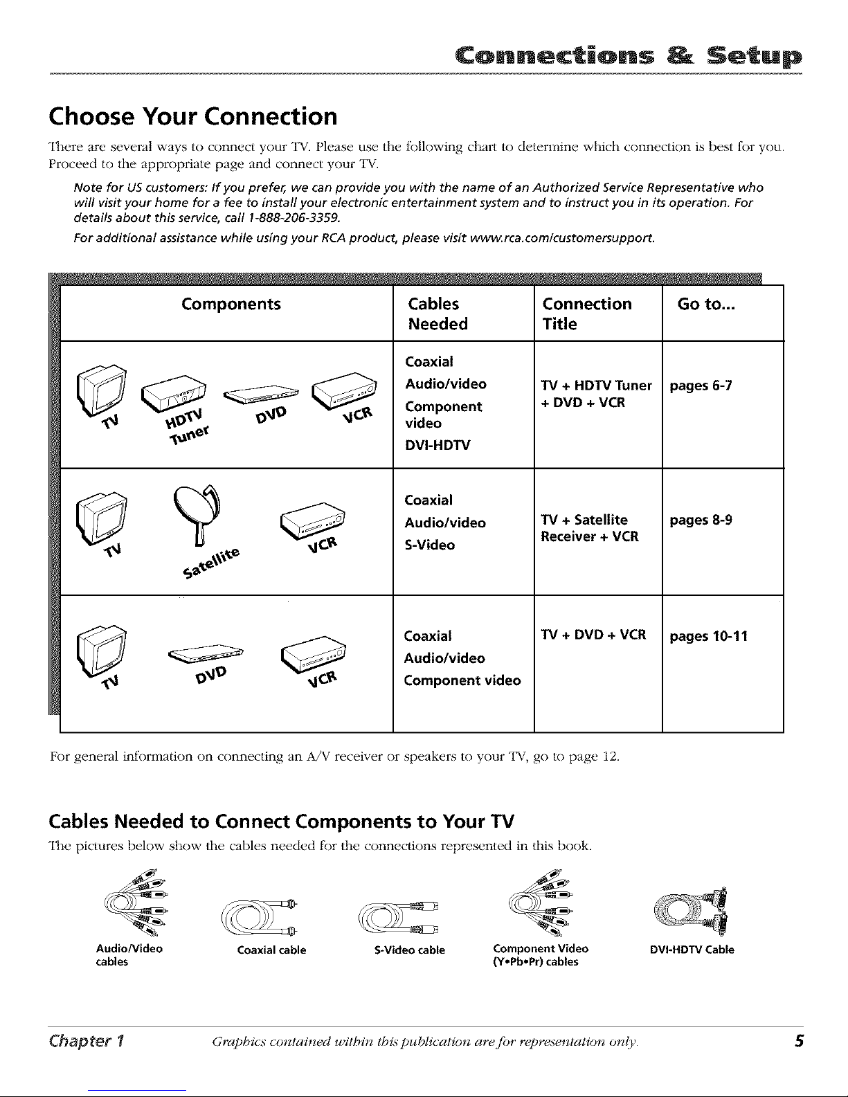
Choose Your Connection
There are several ways to connect your TV. Please use the following chart to determine which connection is best for you.
Proceed to the appropriate page and connect your TV.
Note for US customers: If you prefer, we can provide you with the name of an Authorized Service Representative who
will visit your home for a fee to install your electronic entertainment system and to instruct you in its operation. For
details about this service, call I_88&206-3359.
For additional assistance while using your RCA product, please visit www_rca.com/customersupport.
Components
Cables
Needed
Coaxial
Audio/video
Component
video
DVI-HDTV
Coaxial
Audio/video
S-Video
Coaxial
Audio/video
Component video
Connection
Title
TV + HDTV Tuner
+ DVD + VCR
TV + Satellite
Receiver + VCR
TV + DVD + VCR
Go to...
pages 6-7
pages 8-9
pages 10-11
For general information on connecting an A/V receiver or speakers to your TV, go to page 12.
Cables Needed to Connect Components to Your TV
The pictures below show the cables needed for the connections represented in this book.
Audio/Video Coaxial cable S-Video cable Component Video
cables (Y.Pb.Pr) cables
DVI_HDTV Cable
Chapter 1 Graphics contained within lhis publication ar¢ fi)r r¢presentation only.

¢onn_ctiQns _ Setup
9_9
®
SATELLITERECDVER
VCR
AUDIO OUT
LR Y
DVDPLAYER
i)B pR
6 Graphics contained within lhispublication ar_fi_r r_presentation only. Chapter 1
Connections Setup
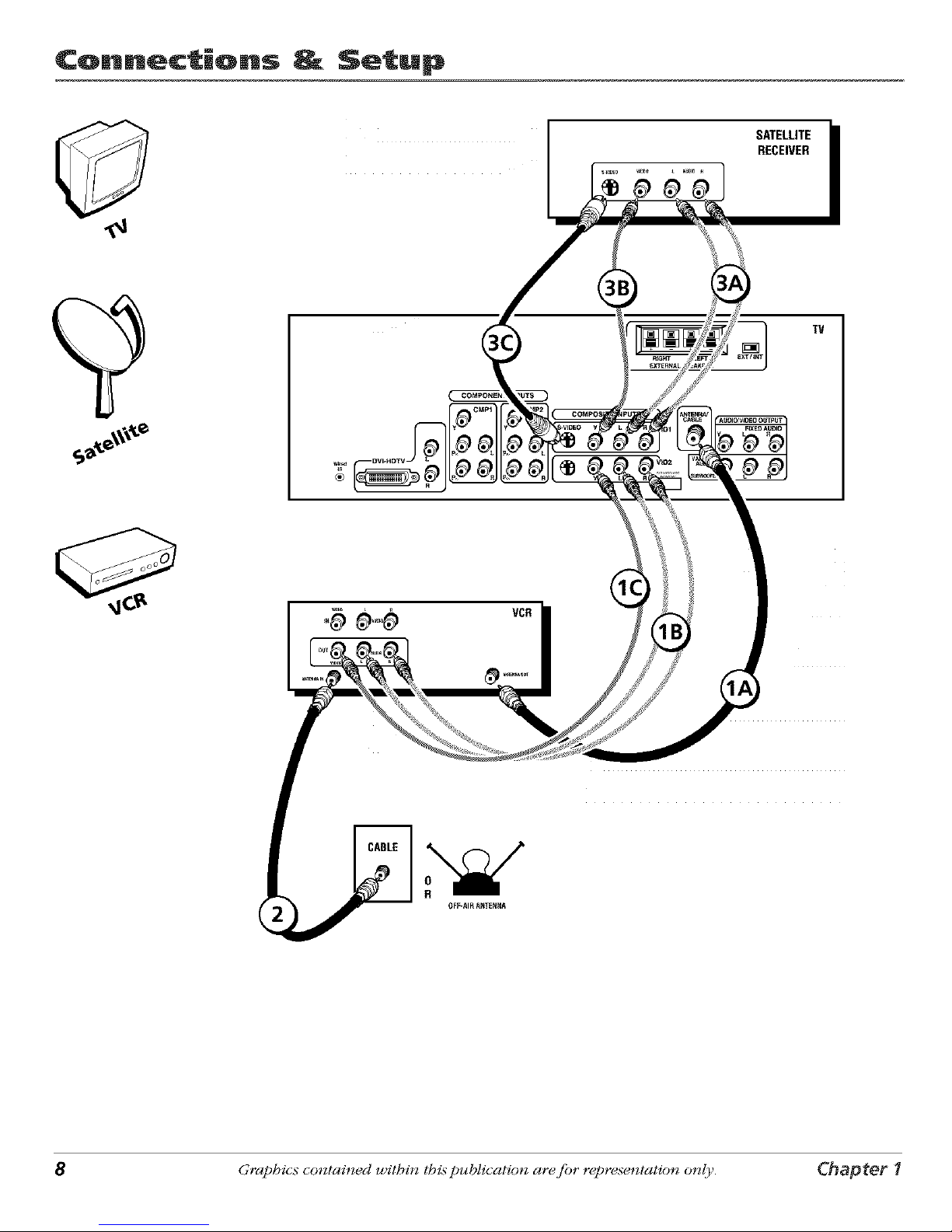
TV + HDTV Tuner + VCR + DVD Player
1. Make sure cable or antenna and/or satellite is connected to your VCR.
A. Connect the coaxial cable frol_qyour cable outlet or antenna to the antenna input on tile HDTV Tuner.
B. Connect the satellite dish antenna to the satellite input on the HDTV Tuner.
2. Make the video connection between your HDTV Tuner and the TV.
A. Best Conneclion: DVI-HDTV
Connect a DVI-HDTV cable to the DVI-HDTV iack on the back of your HDTV Tuner. Connect the other end of the
cable to the DVI-HDTV input on the back of "IV.
- OR -
B. Very Good Connection: Connect three video grade cables to the CMP1 Y PB PR jacks on the back of the TV and to
|he Y PB PR jacks on the HDTV Tuner.
Notes: The DVI-HDTV and Y PBPRjacks send the digital cable signal to the TV in digital and analog formats,
respectively.
3. Make the audio connection between your HDTV Tuner and the TV (to match your video connection).
A. If you used the DVI-HDTV jack:
Connect the audio (white and red) cables to the DVI-HDTV L and R audio jacks on the back of the TV and to the
Audio Output jacks on the HDTV Tuner.
- OR -
B. If you used the Component Video jacks:
Connect the audio (white and red) cables to the CMP1 L and R audio jacks on the back of the TV and to the Audio
Output jacks on tile HDTV Tunei:
4. Connect your HDTV Tuner to your VCR.
A. Connect a coaxial cable to the HDTV Tuner's antenna output and to VCR's antenna input.
B. Connect the audio (white and red) cables to the Audio Output jacks on the HDTV Tuner and to the Audio Input
jacks on the VCR.
C. Connect the video cable to the Video Output jack on the HDTV Tuner and to the Video Input iack on the VCR.
5. Connect your VCR to your TV.
A. Connect a coaxial cable to the VCR's antenna output and to the ANTENNA/CABLE Input iack on tile TV.
B. Connect the audio (whim and red) cables to the VID2 L/MONO and R audio jacks on the back of the TV and to the
Audio Output iacks on the VCR.
C. Connect the video cable to the VID2 V (video) jack on the back of the "IV and to the Video Output jack on the VCR.
6. Connect your DVD player to your TV.
A. Connect tile audio (white and red) cables to the CMP2 L and R audio iacks on the back of the "IV and to the Audio
Output jacks on the DVD player.
B. Connect three video grade cables to the CMP2 Y PB PR iacks on the back of the "IV and to the Y PB PR jacks on the
DVD player.
Notes: If your DVD player doesn't have Y PBPRjacks, but does have an S-Videojack, connect the player to the TV's
VID1 S-VIDEOjack using an S-Video cable.
If your DVDplayer doesn't have an S-Videojack, connect the player to the TV'sVID1 V (video)jack using a video
cable.
Important: If you use the TV's VID1S-VIDEOor V (video)jack to connect the DVDplayer, you must connect the
audio cables to the TV's VID1 L/MONO and Rjacks.
Go to page 15
Chapter 1 Graphics contained within this publication ar_ fi_r r_presentation only. 7
¢onn_ctiQns _ Setup
SATELLITE
RECEIVER
TV
8 Graphics contained within thispublication ar_fi_r r_presentation only. Chapter 1
Connections Setup
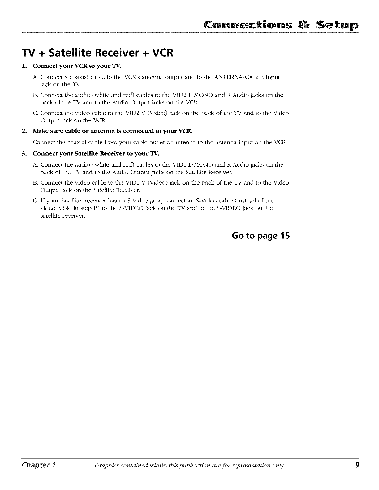
TV + Satellite Receiver + VCR
1. Connect your VCR to your TV.
A. Connect a coaxial cable to the VCR's antenna output and to the ANTENNA/CABLE Input
jack on file TV.
B. Connect the audio (white and red) cables to the VID2 L/MONO and R Audio jacks on the
back of the TV and to the Audio Output jacks on file VCR.
C. Connect the video cable to the VID2 V (Video) jack on the back of file TV and to the Video
Output jack on the VCR.
2. Make sure cable or antenna is connected to your VCR.
Connect the coaxial cable fi'om your cable outlet or antenna to file antenna input on the VCR.
3. Connect your Satellite Receiver to your TV.
A. Connect the mldio (white and red) cables to the VID1 L/MONO and R Audio jacks on the
back of the TV and to the Audio Output jacks on file Satellite Receiver.
B. Connect the video cable to the VID1 V (Video) jack on the back of the TV and to the Video
Output jack on the Satellite Receiver.
C. If your Satellite Receiver has an S-Video jack, connect an S-Video cable (instead of the
video cable in step B) to the S-VI1)EO jack on the TV and to the S-VI1)EO jack on the
satellite receiver.
Go to page 15
Chapter 1 Graphics contained within tbis publication are fi)r representation only. 9
¢onn_ctiQns _ Setup
DVDPLAYER
AIJD_OOUT
y PB PR L R
TV
10 Graphics contained within lhis publication ar_ fi_r r_presentation only. Chapter 1

Connections Setup
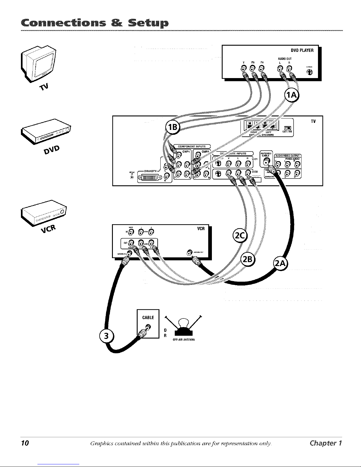
TV + DVD + VCR
1. Connect your DVD Player to your TV.
A. Connect the audio (white and red) cables to the CMP1 L and R Audio jacks on the back of
tim TV and to the Audio Output iacks on the DVD player.
B. Connect three video grade cables to the CMP1 Y PB PR iacks on the back of the TV and to
llle Y PB PR jacks on the DVD player.
Notes:
If your DVDplayer does not have YPBPRjacks, but does have an S-Videojack, connect the
player to the VID1S-VIDEOjack on the TVusing an S-Videocable.
If your DVD player does not have an S-Videojack, connect the player to the VID1 V (Video)
jack on the back of the TVusing a video cable.
Important: If you use the VIDI S-VIDEOor V (Video)jack to connect your TV to the DVD
player, you must connect the audio cables to the VIDI L/MONO and Rjacks on the T_
2. Connect your VCR to your TV.
A. Connect a coaxial cable to the VCR's antenna output and to the ANTENNA/CABLE Input
jack on the TV.
B. Connect the audio (white and red) cables to the VID2 L/MONO and R Audio iacks on the
back of the TV and to the Audio Output iacks on the VCR.
C. Connect the video cable to the VID2 V (Video) iack on the back of the TV and to the Video
Output jack on the VCR.
3. Make sure cable or antenna is connected to your VCR.
Connect the coaxial cable from your cable outlet or antenna to tim antenna input on the VCR.
Go to page 15
Chapter 1 Graphics contained within this publication are fi)r representation only. 11
Connections Setup
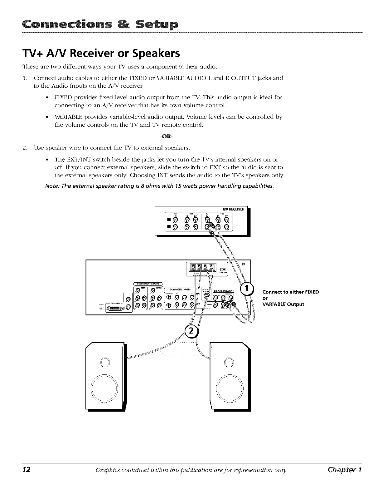
TV+ A/V Receiver or Speakers
These are two different ways your TV uses a co_:qponent to hear audio.
1. Connect audio cables to either the FIXED or VARIABLE AUDIO L and R OUTFUT jacks and
to the Audio Inputs on the A/V receiver.
• FIXED provides fixed-level audio oulput from the "IV. This audio output is ideal for
connecting to an A/V receiver that has its own volume control.
• VARIABLE provides variable-level audio output. Volume levels can be con_olled by
the volm:qe controls on the TV and TV remote con_ol.
-O1R-
2. Use speaker wire to connect the "IV to external speakers.
• The EXT/INT switch beside the iacks let you turn the TV's internal speakers on or
off. If you connect external speakei:s, slide the switch to EXT so the audio is sent to
lhe external speakers only. Choosing 1NT sends the audio to the TV's speakei:s only.
Note: The external speaker rating is8 ohms with 15 watts power handling capabilities.
f
m_ _ _ REmWR
I I
,,__
..... _
;;;;; rA_vl_oou_
\
Connect to either FIXED
or
VARIABLE Output
12 Graphics contained within lhis publication ar_ fi_r r_presentation only. Chapter 1

Connections Setup
Explanation of Jacks (in alphabetical order)
This section desclibes the iacks you can use to make connections. There are several ways to
connect components to your TV.
ANTENNA/CABLE Lets you connect a coaxial cable to receive the signal from the
antenna, cable, cable box, or if using the examples on pages 6-11, a VCR.
COMPONENT INPUTS
_=_ CMP1 _ CMP2
.... p
COMPOSITE INPUTS
_) _io2
Chapter I
AUDIO/VIDEO OUTPUT Lets you connect an amplifier or audio receiver for improved
sound quality" or an external video monitor:
• FIXED AUDIO L/R Provides fixed-level audio output from the "IV. This audio
output is ideal tBr connecting an A/V receiver when you want to control the volume
through the A/V receivei:
• VARIABLE AUDIO Provides variable-level audio output. Volmne levels am
controlled by the volume controls on the "IV and remote control.
• SUBWOOFER Provides lower bass audio frequencies from the "IV to a subwoofer.
Note: If you've connected a subwoofer, make sure you set the External Subwoofer
option in the Sound menu. Go to page 33 for instructions.
COMPONENT INPUTS Lets you connect a component video source, such as a DVD
player.
• CMP1 Y PB PR (Component Video) Provides optimum picture quality because
the video is separated into three signals. Use three video-grade cables for the
connection. When using CMP1 Y PB PR, make sure to connect left and right audio
cables to the CMP1 L and R Audio Input iacks.
• CMP1 L (Audio) Provides left audio connection. The left audio connector is
usually white.
• CMP1 R (Audio) Provides right audio connection. The right audio connector is
usually red.
• CMP2 Y PB PR, and L and R Audio Allows you to connect a second component
video source. Their descriplion is the same as CMP1 above. When using CMP2 Y PB
PR, make sure you connect the left and right audio cables to the CMP2 Audio iacks.
COMPOSITE INPUTS Lets you connect anolher component such as a VCR, DVD
player, or laserdisc player. Its AUDIO iacks are the same as described for CMP1 above.
• VID1 S-VIDEO Provides better picture quality than the video jacks (VID1 and 2
Video) because the color part of the picture is separated from the black and white
part of the picture. When using VID1 S-VIDEO, make sum to connect left and right
audio cables to the VID1 L/MONa and R Audio Input jacks.
• VID1 V (Video) Provides composite video connection. The video connector is
usually yellow.
• VID2 S-VIDEO, V and L/MONa and R Audio Allows you to connect a component
such as a VCR, DVD playeL or laserdisc player. Their description is the same as
VID1 above.
Note: For each VIDjack group (VIDI and VID2),you may connect either an S-Video
or Video cable. Do not connect both at the same time in either of the VIDjack
groups. Continues on nextpage...
Graphics contained within this publication are fi)r representation only. 13
 Loading...