

Page 1
i
i
i
NIUM
Page 2
Important information
I
WARNING
To reduce the risk of fire or electric shock, do
not expose this product to rain or moisture.
CAUTION
THISPRODUCTUTILIZESA LASER.USE
OFCONTROLSORADJUSTMENTSOR
PERFORMANCEOFPROCEDURESOTHER
THANTHOSESPECIFIEDHEREINMAY
RESULTIN HAZARDOUSRADIATION
EXPOSURE.DONOTOPENCOVERSAND
DONOTREPAIRYOURSELEREFER
SERVICINGTOQUALIFIEDPERSONNEL.
Note:
This DVD player is designed and
manufactured to respond to the Region
Management Information. If the Region
number of a DVD disc does not
correspond to the Region number of this
DVD player, this DVD player cannot play
the disc. The Region number for this DVD
player is Region No 1.
CLASS 1
LASER
PRODUCT
I
,_ This symbol indicates "dangerous
voltage" inside the productthat
presentsa risk of electric shock or
personal injur%
Thissymbol indicates that this product incorporates double
insulation between hazardous mains voltage and user
accessibleparts. When servicing useonly identical
replacement parts.
,_ This symbol indicates importantinstructions accompanying the
product.
The apparatus shall not be exposed to dripping or splashing and that no objects filled with liquids, such as
vases, shall be placed on the apparatus.
Referto the identificationlrating label located on the backpanel of your product for its proper operating
voltage.
FCCRegulations statethat unauthorized changes or modifications to this equipment mayvoid the user's
authority to operate it.
Caution: Using video games or any external accessory with fixed images for extended periods of time
can cause them to be permanently imprinted on the picture tube (or projection W picture tubes). ALSO,
some networklprogram logos, phone numbers, black borders (sides, top and bottom), etc. may cause
similar damage. This damage is not covered by your warranty.
Cable "iV Installer: Thisreminder is provided to call your attention to Article 820-40 of the National
Electrical Code(Section 54 of the Canadian Electrical Code, Part I) which provides guidelines for proper
grounding and, in particular, specifies that the cable ground shall be connected to the grounding system of
the building as closeto the point of cableentry as practical
Warning: Do not use the Freeze feature for an extended period of time. This can cause the image to be
permanently imprinted on the picture tube. Such damage is not covered by your warranty Press any button
to unfreeze the picture at any time.
Product Registration
Please fill out the product registration card (packed separately) and return it immediately, or register onqine at tea,tom, Returning the card allows us to contact you
if needed.
Product Information
Keep your sales _ceipt to obtain warranty parts and service and for proof of purchase. Attach it here and _cord the _rial and model numbers in ease you need
tbem. These numbers are located on the product.
Model No.
Serial No.
Purchase Date:
Dealer/Address/Phone:
Page 3
important Information
IMPORTANT SAFETY INSTRUCTIONS
1. Read these instructions.
2. Keep these instructions.
3. Heed all warnings.
4. Follow all instructions.
5. Do not use this apparatus near water.
6. Clean only with dry cloth.
7. Do not block any ventilation openings. Install in accordance with the manufacturer's instructions.
8. Do not install near any heat sources such as radiators, heat registers, stoves, or other apparatus (including amplifiers) that produce heat.
9. Do not defeat the safety purpose of the polarized or grounding-type plug. A polarized plug has two blades with one wider than the other. A
grounding type plug has two blades and a third grounding prong. The wide blade or the third prong is provided for your safety. If the provided
plug does not fit into your outlet, consult an electrician for replacement of the obsolete outlet.
10. Protect the power cord from being walked on or pinched particularly at plugs, convenience receptacles, and the point where they exit from the
apparatus.
11. Only use attachments/accessories specified by the manufacturer.
12. Use only with the cart, stand, tripod, bracket, or table specified by the manufacturer, or sold with the apparatus. When a cart is used,
use caution when moving the cart/apparatus combination to avoid injury from tip-over.
13. Unplug this apparatus during lightning storms or when unused for long periods of time.
14. Refer all servicing to qualified service personnel. Servicing is required when the apparatus has been damaged in any way, such as power-supply
cord or plug is damaged, liquid has been spilled or objects have fallen into the apparatus, the apparatus has been exposed to rain or moisture, does
not operate normally, or has been dropped.
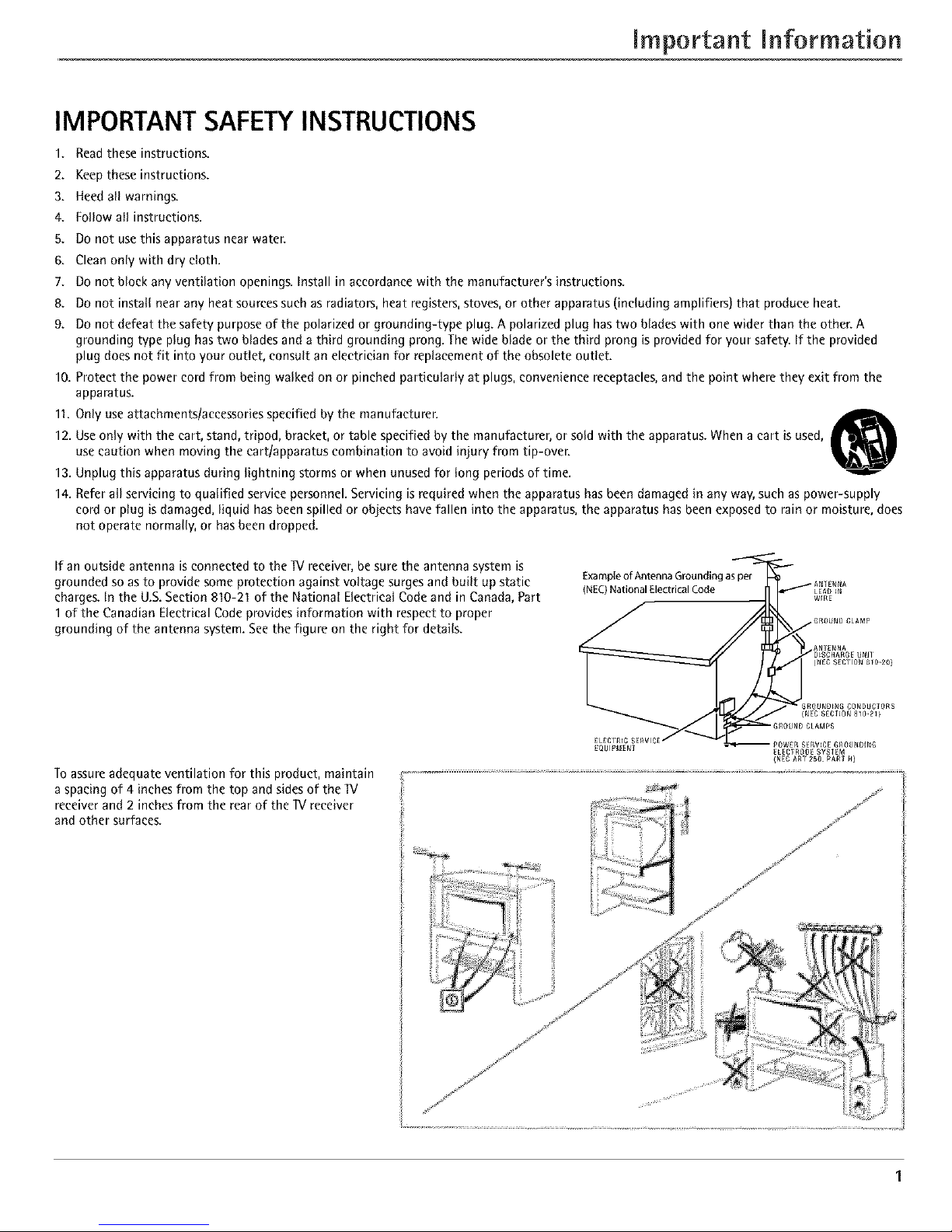
If an outside antenna is connected to the W receiver, be sure the antenna system is
grounded so as to provide some protection against voltage surges and built up static
charges. In the U.S. Section 810-21 of the National Electrical Code and in Canada, Part
1 of the Canadian Electrical Code provides information with respect to proper
grounding of the antenna system. See the figure on the right for details.
Example of Antenna Grounding as per
(NEC)National Electrical Code
Toassureadequate ventilation for this product, maintain
aspacing of 4 inches from the top and sidesof the "IV
receiverand2 inchesfrom the rear of the TVreceiver
and other surfaces.
..../. i ;
Page 4
Introduction
Key Features Overview
Your IV is equipped with features that will add to your IV viewing experience. The following information
summarizes a few of these features. Chapter 4 provides more information about the rest of the IV's features and
how to use them.
DVI-HDTV L/MOI,tO
PIPexample
POP example
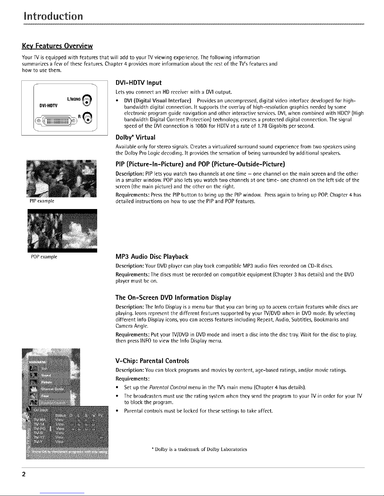
DVI-HDTV Input
Letsyou connect an HD receiver with a DVIoutput.
* DVI (Digital Visual Interface) Providesan uncompressed,digitat video interface developed for high-
bandwidth digital connection. It supports the overlay of high-resolution graphics neededby some
electronic program guide navigation and other interactive services.DVI,when combined with HDCP(High
bandwidth Digitat Content Protection) technology, creates a protected digitat connection. Thesignal
speedof the DVIconnection is 1080ifor HDIVat a rate of 1.78 Gigabits per second.
Dolby* Virtual
Available only for stereo signals.Createsa virtualized surround sound experience from two speakersusing
the Dolby ProLogic decoding. It provides the sensationof being surrounded by additional speakers.
PIP (Picture-In-Picture) and POP (Picture-Outside-Picture)
Description: PIP lets you watch two channels at one time - one channel on the main screen and the other
in a smaller window. POPalso lets you watch two channels at one time- one channel on the left side of the
screen (the main picture) and the other on the right.
Requirements: Press the PiP button to bring up the PiP window. Press again to bring up POE Chapter 4 has
detailed instructions on how to use the PIP and POPfeatures.
MP3 Audio Disc Playback
Description: Your DVDplayer can play back compatible MP3 audio files recordedon CD-R discs.
Requirements: The discsmust be recordedon compatible equipment (Chapter 3 hasdetails)and the DVD
player must beon.
The On-Screen DVD Information Display
Description: The Info Display is a menu bar that you can bring up to access certain features while discs are
playing. Icons represent the different features supported by your IV/DVD when in DVD mode. By selecting
different Info Display icons, you can accessfeatures including Repeat, Audio, Subtitles, Bookmarks and
Camera Angle.
Requirements: Put your IV/DVD in DVD mode and insert a disc into the disc tray. Wait for the disc to play,
then press INFO to view the Info Display menu.
V-Chip: Parental Controls
Description: You can block programsand movies by content, age-basedratings, and/or movieratings.
Requirements:
* Set up the Parental Control menu in the IV's main menu (Chapter 4 hasdetails).
* Thebroadcasters must usethe rating systemwhen they send the program to your IV in order for your IV
to block the program.
* Parentalcontrols must be lockedfor these settings to take affect.
* Dolby is a trademark of Dolby Labora/ories
2
Page 5
TabJe of Contents
IMPORTANT SAFETY INSTRUCTIONS ................ 1
Introduction
Key Features Overview ............................................... 2
DVI-HDTV Input ............................................. 2
Dolby* Virtual ................................................... 2
PIP (Picture-In-Picture) and POP
(Picture-Outside-Picture) ................................ 2
MP3 Audio Disc Playback ................................. 2
The On-Screen DVD Information Display ........ 2
V-Chip: Parental Controls ................................. 2
Chapter 1: Connections & Setup
Things to Consider Before You Connect .................. 5
Protect Against Power Surges .......................... 5
Protect Components from Overheating .......... 5
Position Cables Properly to Avoid Audio
Interference ..................................................... 5
Important Stand and Base Safety
Information ..................................................... 5
Use Indirect Light .............................................. 5
Cables Needed to Connect Components to
Your TV ............................................................ 5
Choose Your Connection ............................................ 6
TV/DVD + HD Receiver + VCR ................................... 7
TV/DVD + Satellite Receiver + VCR .......................... 8
W/DVD + VCR ............................................................ 9
TV/DVD+ A/V Receiver or Speakers ........................ 10
Explanation of Jacks ................................................. 11
The Front of Your TV/DVD ....................................... 12
Front Inputs ..................................................... 12
Front Panel Buttons ........................................ 12
Put batteries in the remote ..................................... 12
Turn on the TV/DVD ................................................. 12
Complete the Initial Setup ...................................... 12
Set the Menu Language ................................. 13
Complete Auto Channel Search ..................... 13
Changing Lists and Labels .............................. 13
Auto Convergence .......................................... 13
Chapter 2: Using the Remote Control
The Buttons on the Remote Control ...................... 14
Using the INPUT Button ................................. 15
Programming the Remote to Operate Other
Components ............................................................ 15
Find Out If You Need to Program the
Remote .......................................................... 15
Programming the Remote .............................. 15
How to Use the Remote After You've
Programmed It .............................................. 16
Remote Control Codes ............................................. 16
Chapter 3: Playing DVDs
Regional Coding ....................................................... 18
Using Different Menus ............................................ 18
Loading and Playing Discs ....................................... 18
To Load and Play a Disc .................................. 18
Using a Disc Menu ................................................... 18
Using the On-Screen Info Display .......................... 18
Time Display .................................................... 19
Selecting a Title ............................................... 19
Selecting a Chapter ......................................... 19
Selecting Subtitles ........................................... 19
Changing the Audio Language ...................... 20
Using the Repeat Feature ............................... 20
Using Bookmarks ............................................ 21
Changing the Camera Angle .......................... 21
Chapter 4: Using the TV's Features
Channel Banner ........................................................ 22
Why You Should Use the Autotuning Feature ...... 22
How to Set Up the Autotuning Feature ........ 22
Parental Controls and V-Chip ................................. 23
How V-Chip Works .......................................... 23
V-Chip TV Rating ............................................. 23
Blocking Specific Content Themes ................. 24
Viewing Specific Content Themes .................. 25
V-Chip Movie Rating Limit ............................. 25
V-Chip Unrated Program Block ...................... 25
Lock/Unlock Parental Controls ....................... 25
Front Panel Block ............................................ 25
PIP (Picture-in-Picture} and POP
(Picture-outside-Picture} Operation ................... 26
PIP and POP Buttons ....................................... 26
Chapter 5: Using the DVD Menu
The DVD's Menu System .......................................... 27
The Play/Resume Play Option .................................. 27
The Play Mode Menu ............................................... 27
Selecting a Play Mode .................................... 27
How to Create a Program .............................. 27
Editing a Program ........................................... 28
Deleting Chapters ........................................... 28
AutoPlay .......................................................... 28
Dub Assist ........................................................ 28
IntroScan ......................................................... 28
3
Page 6
Table of Contents
The Lock Menu ......................................................... 28
Locking Your DVD ........................................... 29
Unlocking Your DVD ....................................... 29
Changing Your Password ................................ 29
Setting the Ratings Limits .............................. 29
Unrated Titles .................................................. 30
System Test ...................................................... 30
The Display Menu ..................................................... 30
TV Image ......................................................... 30
On-Screen Displays .......................................... 30
The Sound Menu ...................................................... 31
Digital Output ................................................. 31
Sound Logic ..................................................... 31
The Languages Menu ............................................... 31
Changing the Player Menus, Disc Menus,
Audio or Subtitles Language Preferences ... 31
Glossary ..................................................................... 32
Code List ................................................................... 32
Chapter 6: Using the TV's Menu System
Sound Menu .............................................................. 33
Picture Menu ............................................................ 33
Channel Guide Menu ............................................... 34
Time Menu ................................................................ 34
Parental Control Menu ............................................ 34
PIP Menu ................................................................... 34
Setup Menu .............................................................. 35
Chapter 7: Information Displays
Using the Info Display .............................................. 36
Audio CD Info Display ..................................... 36
MP3 Info Display ............................................. 36
Video CD Info Display ..................................... 36
Using the Time Display ................................... 36
Selecting a Specific Track ................................ 36
Selecting a Specific Index ............................... 37
Selecting a Play Mode .................................... 37
Using the Program Play Feature .................... 37
Editing a Playlist .............................................. 38
Using the Repeat Feature ............................... 38
A,B Repeat ...................................................... 38
Changing the Audio Channel Output ........... 38
Using IntroScan ............................................... 39
Using Bookmarks ............................................ 39
Dub Assist ........................................................ 39
Chapter 8: Other Information
Troubleshooting ........................................................ 40
Care and Cleaning .................................................... 43
Handling Cautions .......................................... 43
Formation of Condensation ........................... 43
Limited Warranty ..................................................... 44
Accessories ................................................................ 45
4
Page 7
Things to Consider Before You Connect
Protect Against Power Surges
• Connect all components before you plug any of their power cords into the wall outlet.
• Turn off the IV and!or component before you connect or disconnect any cables.
• Make sure all antennas and cablesare properly grounded. Referto the Important Safety Instructions on page 1.
Protect Components from Overheating
• Don't block ventilation holes on any of the components. Arrange the components so that air can circulate freely.
• Don't stack components.
• When you place components in a stand, make sure you allow adequate ventilation.
• If you connect an audio receiver or amplifier, place it on the top shelf so the heated air from it won't flow around
other components.
Position Cables Properly to Avoid Audio Interference
• Insert each cable firmly into the designated jack.
• If you place components above the IV, route all cables down the side of the back of the 1V instead of straight
down the middle of the IV.
• If your antenna uses 300-ohm twin lead cables, do not coil the cables. Also, keep the twin lead cables away from
audio/video cables.
Important Stand and Base Safety Information
Choose the location for your IV carefully. Place the IV on a stand or base that is of adequate size and strength to
prevent the IV from being accidentally tipped over, pushed off, or pulled off. This could cause personal injury and!or
damage the IV. Refer to the Important Safety Instructions on page 1.
Use Indirect Light
Don't place the IV where sunlightor room lightingwill he directed toward the screen. Usesoft or indirect lighting.
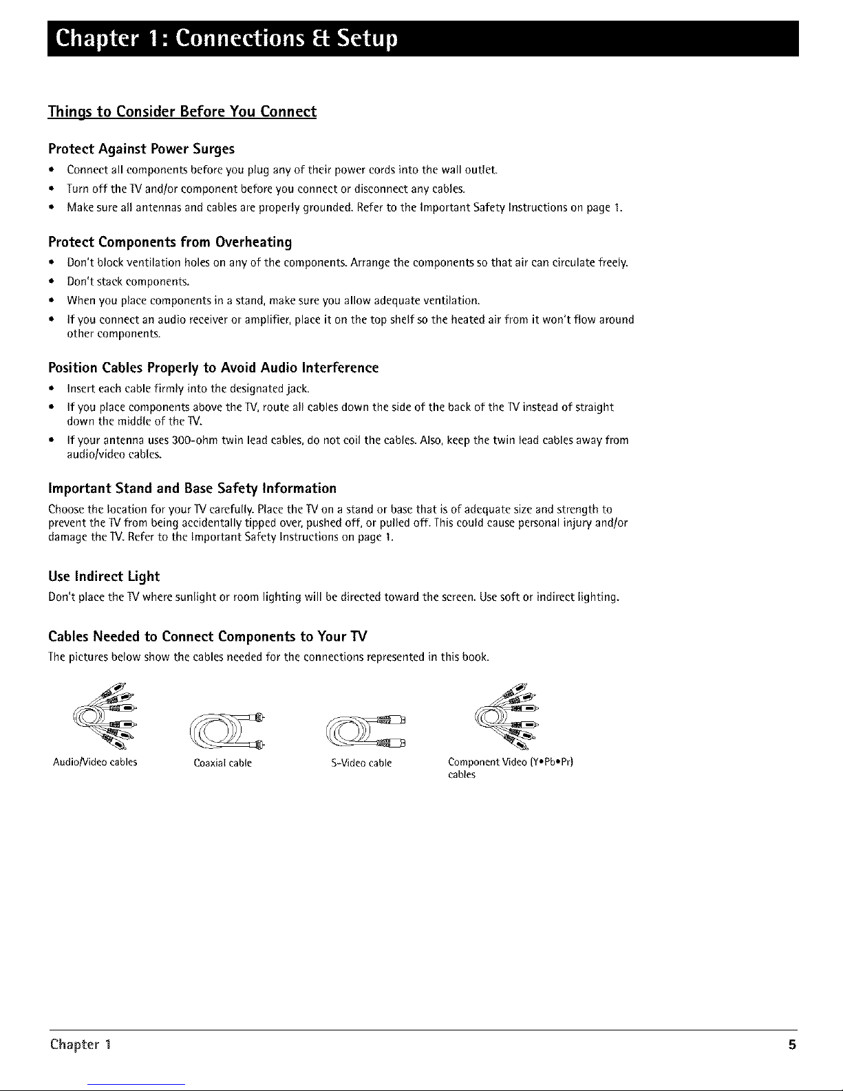
Cables Needed to Connect Components to Your TV
Thepictures below show the cables neededfor the connections representedin this book.
Audio/Video cables
Coaxial cable S-Videocable Component Video (Y,Pb-Pr)
cables
Chapter 1 5
Page 8
Connections [{ Setup
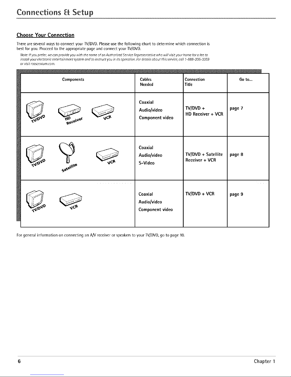
Choose Your Connection
There are several ways to connect your _//DVD, Please use the following chart to determine which connection is
best for you. Proceed to the appropriate page and connect your _V/DVD.
Note:If youprefer,we canprovide you with thenameof on AuthorizedServiceRepresentativewho will visit yourhome for a feeto
inst_il yourelectronic entert_inment systemand toinstruer youin itsoperation. Fordetails about thisservice,earl 1-888-206-3359
or visit rcascenium.com.
Components
Cables
Needed
Coaxial
Audio/video
Component video
Coaxial
Audio/video
S-Video
Coaxial
Audio/video
Component video
Connection
Title
TV/DVD +
HD Receiver+ VCR
TV/DVD + Satellite
Receiver + VCR
TV/DVD+ VCR
Go to...
page 7
page 8
page 9
For general information on conneeting an A/V receiver or speakers to your TV/DVD, go to page 10,
6 Chapter 1
Page 9
Connections Setup
TWDVD
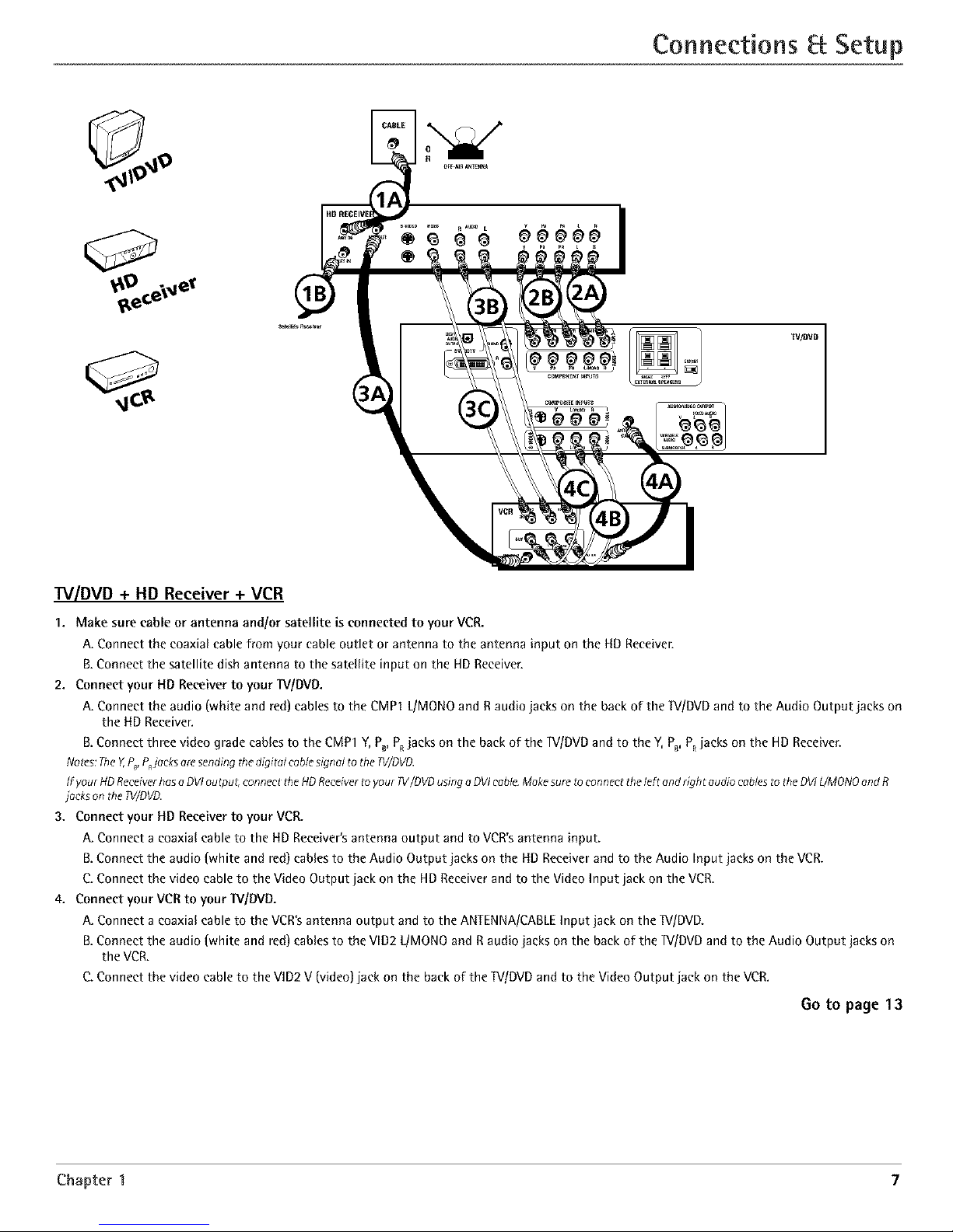
TV/DVD + HD Receiver + VCR
1. Make sure cable or antenna and/or satellite is connected to your VCR.
A. Connect the coaxial cable from your cable outlet or antenna to the antenna input on the HD Receiver.
B,Connect the satellite dish antenna to the satellite input on the HD Receiver,
2. Connect your HD Receiver to your W/DVD.
A. Connect the audio (white and red) cables to the CMP1 L/MONO and R audio jacks on the back of the TV/DVD and to the Audio Output jacks on
the liD Receiver.
B. Connect three video grade cables to the CMP1 Y, P_, PRjacks on the back of the TV/DVD and to the Y,PB, PRjacks on the HD Receiver.
Notes:They P_P,jacksaresending thedigital cablesignal tothe 1V/DVD.
If yourHD Receiverhasa DVIoutput, connect theHDReceiverto your TV/DVDusinga DVIcable.Makesureto connect theleft andright audio cablesto theDVIL/MONOand R
jackson the TV/DVD.
3. Connect your lid Receiver to your VCR.
A. Connect a coaxial cable to the liD Receiver's antenna output and to VCR's antenna input.
B.Connect the audio {white and red) cables to the Audio Output jacks on the lid Receiver and to the Audio Input jacks on the VCR.
C. Connect the video cable to the Video Output jack on the HD Receiver and to the Video Input jack on the VCR.
4. Connect your VCR to your _//DVD.
A. Connect a coaxial cable to the VCR's antenna output and to the ANTENNA/CABLE Input jack on the ]V/DVD.
B.Connect the audio {white and red) cables to the VlD2 L/MONO and R audio jacks on the back of the ]V/DVD and to the Audio Output jacks on
the VCR.
C. Connect the video cable to the VlD2 V (video] jack on the back of the TV/DVD and to the Video Output jack on the VCR.
6o to page 13
Chapter 1 7
Page 10
Connections Setup
W/DVD
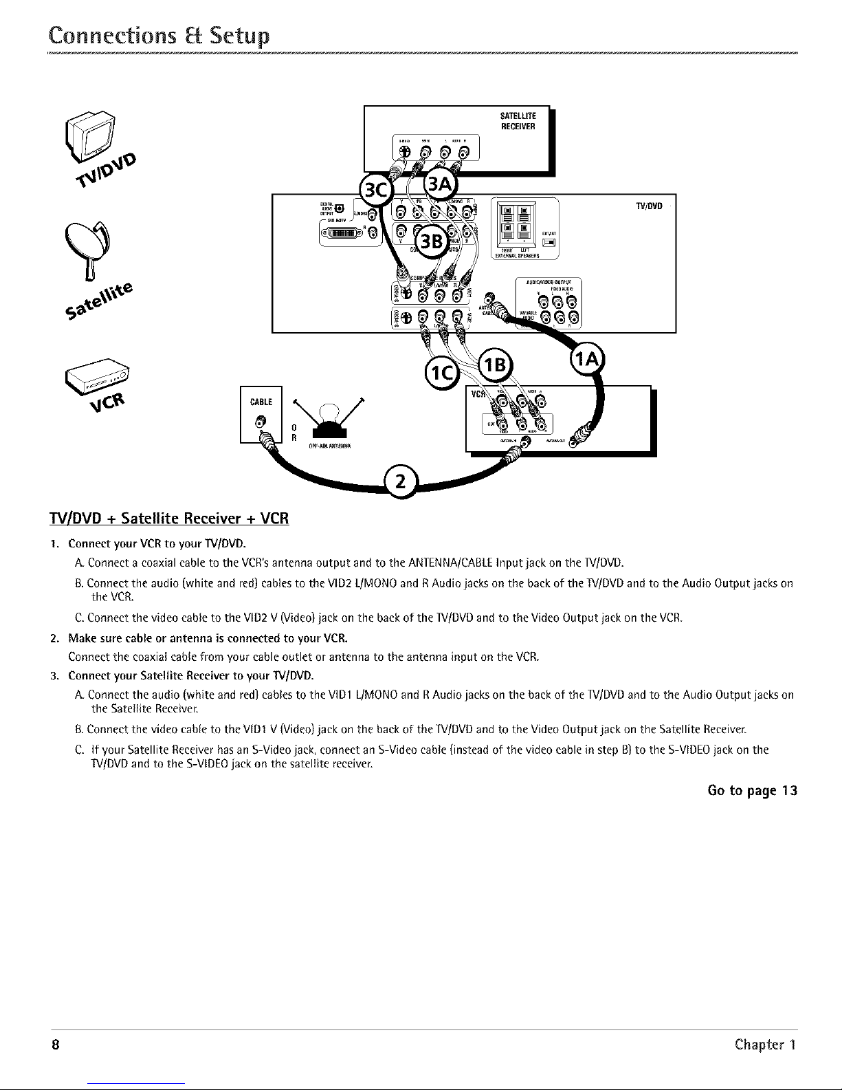
W/DVD + Satellite Receiver + VCR
1. Connect your VCRto your W/DVD.
A. Connect a coaxial cable to the VCR'santenna output and to the ANTENNA/CABLEInput jack on the W/DVD.
& Connect the audio (white and red) cablesto the VlD2L/MONOand RAudio jacks on the backof the W/DVD and to the Audio Output jacks on
the VCR.
C.Connect the video cable to the VID2V (Video)jack on the back of the W/DVD and to the Video Output jack on the VCR.
2. Make sure cable or antenna is connected to your VCR.
Connect the coaxial cablefrom your cable outlet or antenna to the antenna input on the VCR.
3. Connect your Satellite Receiverto your W/DVD.
A. Connect the audio (white and red] cables to the VlD1 L/MONOand RAudio jacks on the back of the lV/DVD andto the Audio Output jacks on
the Satellite Receiver.
[3.Connect the video cable to the VlD1 V(Video) jack on the back of the lV/DVD and to the VideoOutput jack on the Satellite Receiver.
C. If your Satellite Receiverhas an S-Videojack, connect an S-Videocable(instead of the video cable in step B)to the S-VIDEOjack on the
W/DVD and to the S-VIDEOjack on the satellite receiver.
Go to page 13
8 Chapter 1
Page 11
Connections Setup
_t@llll!ll IilPil$
TV/DVO
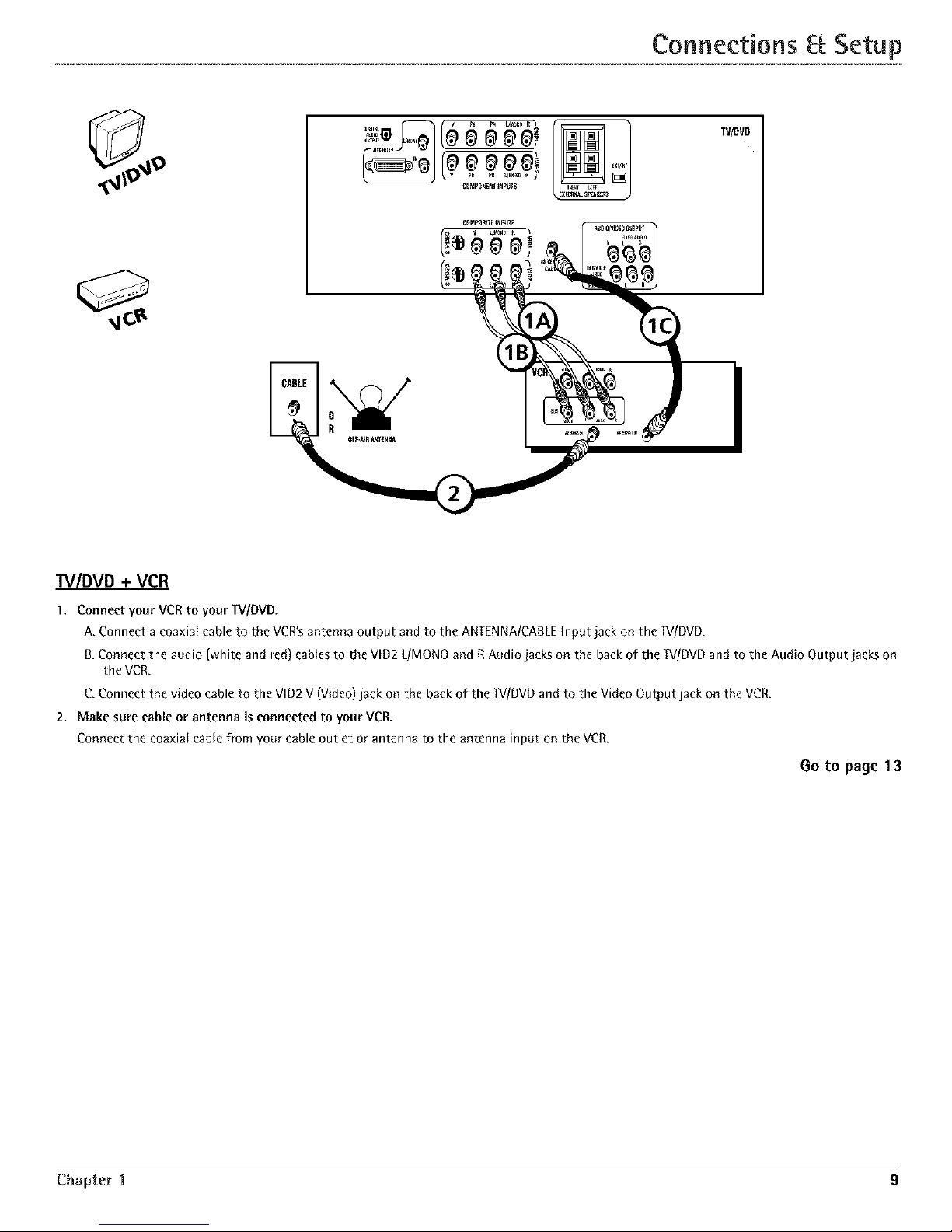
TV/DVD + VCR
1. Connect your VCRto yourTV/DVD.
A. Connect a coaxial cable to the VCR'santenna output and to the ANTENNA/CAILEInput jack on the _[V/DVD.
B.Connect the audio (white and red)cablesto the VlD2 L/MONOand RAudio jacks on the backof the TV/DVDand to the Audio Output jacks on
the VCR.
C.Connect the video cable to the VID2V (Video)jack on the back of the TV/DVDand to the VideoOutput jack on the VCR.
2. Make sore cable or antenna is connected to your VCR.
Connect the coaxial cane from your cableoutlet or antenna to the antenna input on the VCR.
0o to page 13
Chapter 1 9
Page 12
Connections Setup
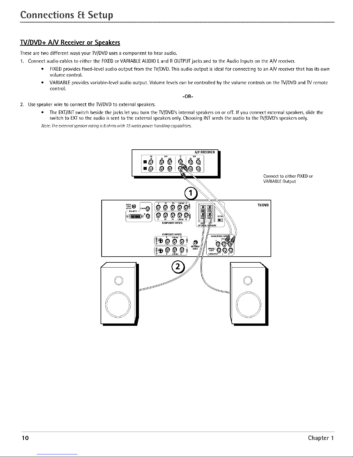
TV/DVD+ A[V Receiver or Speakers
Theseare two different waysyour TV/DVDusesa componentto hear audio.
1. Connect audio cables to either the FIXEDorVARIABLEAUDIO Land ROUTPUTjacks andto the Audio Inputs on the AN receiver.
• FIXEDprovidesfixed-level audio output from the W/DVD. Thisaudio output is ideal for connecting to anAiV receiver that has its own
volume control.
• VARIABLEprovidesvariable-level audio output. Volume levelscan be controlled by the volume controls on the 1V/DVDand TV remote
control.
-OR-
2. Usespeakerwire to connect the "[V/DVDto external speakers.
• TheEXT!INTswitch besidethe jacks let you turn the 1V/DVD'sinternal speakerson or off. If you connect external speakers,slide the
switch to EXTso the audio is sent to the external speakersonly. Choosing INTsendsthe audio to the W/DVD's speakersonly.
Note: Theexternol speoker ra ring is 8 oh ms with 15 watts power hondflng capabilities.
A/V RECEIVER i
IN _A_ TV _R
Connect to either FIXEDor
VARIAgLEOutput
f
TV/DVD
10 Chapter 1
Page 13
Connections Setup
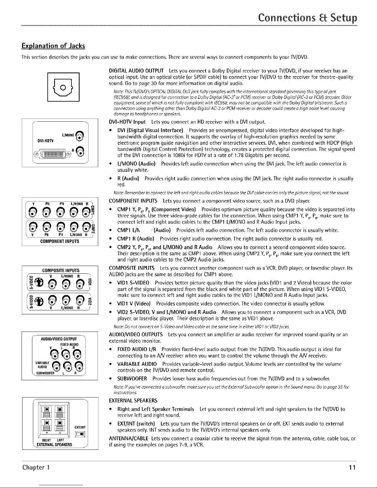
Explanation of Jacks
This section describes the jacks you can use to make connections. There are several ways to connect components to your TV/DVD.
G
J
PB PR L/MOeO R )
COMPONENTINPUTS
COMPOSITEINPUTS
v t._ONO R J
AUDIONIDEOOLITPUT
_ _FIXEDAUDIO
AUDIO
SUBWOOFER L R
RIG P,T LEFT
EXTERMAL SPEAKERS
DIGITAL AUDIO OUTPUT Lets you connect a Dolby Digital receiver to your 1V/DUD, if your receiver has an
optical input. Usean optical cable (or SPDIF cable) to connect your TV/DVD to the receiver for theatre-quality
sound. Go to page 30 for more information on digital audio.
Noto:This?V/DVD'sOPTICALDIGITALOUTjack fully complieswith theint_rna done/standard governing this typeof jack
(IEC958),endisdesignedfor connection toe DolhyDigital [AC-3_orPCM)receiveror DolhyDigital (AC-3orPCM)decodc_Older
equipment;someof whichis not fully compliant with IEC958,maynot be compotibia with theDolbyOigRd bRstreem.Such o
connection usinganything othor thenOolbyDigit_l AC-3or PCMreceiveror decodercouldcreatea high noiselevel,causing
damage to headphonesor speoker_.
DVI-HDW Input Lets you connect an RD receiver with a DVl output.
• DVI {Digital Visual Interface} Provides an uneompressed, digital video interface developed for high-
bandwidth digital connection. It supports the overlay of high-resolution graphics needed by some
electronic program guide navigation and other interactive services. DVl, when combined with HDCP (High
bandwidth Digital Content Protection) technology, creates a protected digital connection. The signal speed
of the DVl connection is 1080i for HD]V at a rate of 1.78 Gigabits per second.
• L/MONO {Audio] Provides left audio connection when using the DVl jack. The left audio connector is
usually white.
• R {Audio] Provides right audio connection when using the DVI jack. The right audio connector is usually
red.
Noto:Rememberto connecttile left andright audio cablesbemuse theDVIcablecarries only thepicturesignal, not thesound.
COMPONENT INPUTS Lets you connect a component video source, such as a DUD player.
* CMP1 Y, Pc, PR{Component Video] Provides optimum picture quality because the video is separated into
three signals. Use three video-grade cables for the connection. When using CMP1 Y, P_,P,, make sure to
connect left and right audio cables to the CMP1 L/MONO and R Audio Input jacks.
* CMP1 L/l_ _{Audio] Provides left audio connection. The left audio connector is usually white.
e CMP1 R {Audio] Provides right audio connection. The right audio connector is usually red.
e CMP2 Y, Pc, PR,and I_/MONO and R Audio Allows you to connect a second component video source.
Their description is the same as CMP1 above. When using CMP2 Y, P_,P_, make sure you connect the left
and right audio cables to the CMP2 Audio jacks.
COMPOSITE INPUTS Lets you connect another component such as a VCR, DVD player, or laserdisc player. Its
AUDIO jacks are the same as described for CMP1 above.
e VlD1 S-VIDEO Provides better picture quality than the video jacks (VID1 and 2 Video] because the color
part of the signal is separated from the black and white part of the picture. When using VlD1 S-VIDEO,
make sure to connect left and right audio cables to the VlD1 L/MONO and RAudio Input jacks.
e VlD1 V {Video] Provides composite video connection. The video connector is usually yellow.
* VID2 S-VIDEO, V and L/MONO and R Audio Allows you to connect a component such as a VCR, DVD
player, or laserdise player. Their description is the same as VID1 above.
Note:Donot connecton S-Videoend Videocableot the sometime in eitherVID1or VlD2jocks.
AUDIO/VIDEO OUTPUTS Lets you connect an amplifier or audio receiver for improved sound quality or an
external video monitor.
• FIXEDAUDIO L/R Provides fixed-level audio output from the W/DVD. This audio output is ideal for
connecting to an AN receiver when you want to control the volume through the AN receiver.
• VARIABLE AUDIO Provides variable-level audio output. Volume levels are controlled by the volume
controls on the ]V/DVD and remote control.
• SUBWOOFER Provides lower bass audio frequencies out from the*[V/DVD and to a subwoofer.
NOto.If you've connectedesubwoofer,makesureyou setthe ExternalSuhwooferoption inthe Soundmenu.Go topage 33for
instructions.
EXTERNALSPEAKERS
• Right and Left Speaker Terminals Let you connect external left and right speakers to the*[V/DVD to
receive left and right sound.
• EXT/INT (switch] Lets you turn the lV/DVD's internal speakers on or off. EXT sends audio to external
speakers only. ]NT sends audio to the *[V/DVD's internal speakers only.
ANTENNA/CABLE Lets you connect a coaxial cable to receive the signal from the antenna, cable, cable box, or
if using the examples on pages 7-9, a VCR.
Chapter 1 11
Page 14
Connections Setup
The Front of Your TV/DVD
Front Inputs
The 1V/DVD has front inputs for convenience: one set of audio/video inputs, an S-Video and a headphone jack. Locate the jacks either on the front of
the 1V/DVD or on one of the sides. You can access the component you connected to the front of the 1V/DVD by pressing the INPUT button on your
remote until FRNTappears on the screen. The jacks are ideal for using a video game console or a eameorder.
Note:Whenconnecting adewce that usesamonaural cable,such assomecameorders,use theLeft[rnonoJinputjack to get soundfrom both speakers.
PHONES Allows you to connect headphones to listen to the sound coming from the 1V/DVD. To adjust volume control of the headphones, press the
VOL > or VOL < button (the volume display appears). Press the arrow up or down button (the headphone volume display appears), then press the right
or left arrow button to adjust the headphone volume.
L/MONO and R AUDIO IN Receives audio from another component such as a VCR, eameorder or video game console.
VIDEO IN Receives video from another component such as a VCR, eamcorder or video game console.
SiVIDEO IN Allows you to connect an S-Video cable from another component. Make sure you also connect audio cables from the component to the
TV/DVD.
Front Panel Buttons
If you cannot locate your remote, you can use the front panel buttons of your W/DVD to operate many of the W/DVD's features.
OPEN/CLOSE Press to open and close disc tray.
STOP Stops disc play.
PLAY Begins disc play.
MENU/OK Brings up the _V Main menu. When in the menu system, selects highlighted items.
CH v Scans down through the current channel list. In the _[V menu system, acts like down arrow button on the remote control and adjusts menu
controls.
CH ^ Scans up through the channel list. In the TV menu system, acts like up arrow button on the remote control and adjusts menu controls.
VOL < Decreases the volume. In the _V menu system, acts like left arrow button on the remote control and adjusts menu controls.
VOL > Increases the volume. In the lV menu system, acts like right arrow button on the remote control and adjusts menu controls.
POWER Turns the TV/DVD on and off.
Put batteries in the remote
o Remove the battery compartment cover from the back of the remote by pushing down on and sliding off the cover.
o Insert 2 "AA" fresh batteries. Make sure the polarities (+ and -) are aligned correctly.
,o Replace the cover.
Turn on the TV/DVD
Press_ on the remote, or press POWER on the 1V/DVD's front panel.
Note:Pressingthe _/ button not only turns onthe_g,butputs theremote into TVmode. 'qVmode"meonsthat the buttons on theremote controloperatethe PV'Sfunetion£
Complete the Initial Setup
Tip
The menu system in your TV allows the lV's features to work properly. The first time you turn on your ]V/DVD,
Toaccess the setup menusmanually, the setup screens appear.
pressMENUand chooseSETUR
12 Chapter 1
Page 15
Connections Setup
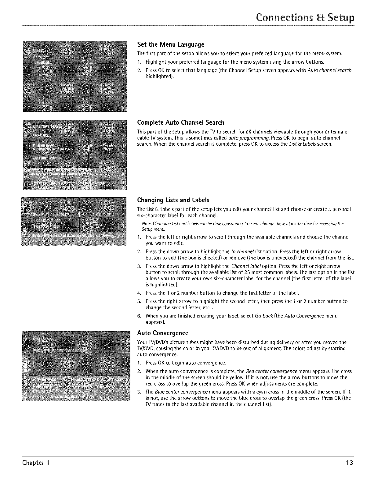
Set the Menu Language
The first part of the setup allows you to select your preferred language for the menu system.
1. Highlight your preferred language for the menu system using the arrow buttons.
2. PressOKtoselectthatlanguage(theChannelSetupsereenappearswithAutoehennelseereh
highlighted).
Complete Auto Channel Search
This part of the setup allows the lV to search for all channels viewable through your antenna or
cable lV system. This is sometimes called auto programming. Press OK to begin auto channel
search. When the channel search is complete, press OK to access the List EfLabels screen.
Changing Lists and Labels
The List 8: Labels part of the setup lets you edit your channel list and choose or create a personal
six-character label for each channel.
Nore:ChangingListend Labelscan betime consuming Youcanchange theseat a later timeby accessingthe
Setup menu.
1, Press the left or right arrow to scroll through the available channels and choose the channel
you want to edit.
2.
3.
4.
5.
Press the down arrow to highlight the In channel list option. Press the left or right arrow
button to add (the box is checked) or remove (the box is unchecked) the channel from the list.
Press the down arrow to highlight the Channel labe! option. Press the left or right arrow
button to scroll through the available list of 25 most common labels. The last option in the list
allows you to create your own six-character label for the channel (the first letter of the label
is highlighted).
Press the 1 or 2 number button to change the first letter of the label.
Press the right arrow to highlight the second letter, then press the 1or 2 number button to
change the second letter, etc...
When you are finished creating your label, select Go back (the Auto Convergence menu
appears).
Auto Convergence
Your TVIDVD's picture tubes might have been disturbed during delivery or after you moved the
TVlDVD, causing the color in your IV/DVD to be out of alignment. The colors adjust by starting
auto convergence.
I. Press OK to begin auto convergence.
2. When the auto convergence is complete, the Redcenter convergence menu appears. The cross
in the middle of the screen should be yellow. If it is not, use the arrow buttons to move the
red cross to overlap the green cross. Press OK when adjustments are complete.
3. The Blue center convergence menu appears with a wan cross in the middle of the screen. If it
is not, use the arrow buttons to move the blue cross to overlap the green cross. Press OK (the
lV tunes to the last available channel in the channel list).
Chapter 1 13
Page 16

Indicator
&&°&&
MUTE SKIP
GUIDE _) GO BACK
DISCMENU INFO
MENU CL[A_t
10 20:30
'0 sO °0
70 80,0
INPUT SOUND,ANT
©o@
REVERS[ PLAY FORWARD
Note:TheVCRt, DVD,VCR2,and
SAT*CABLEbuttonsalso turn on most
RCA,GE,and Proscanproducts.
Tip
Toturn off aBthe RCA,OE,and Proscan
components that areconnected to the T_,
pressON.OFFtwice within two seconds.
Thisfeature only workswith most RCA,
OE,andProscanproducts.
The Buttons on the Remote Control
(0-9) Number Buttons Enter channel numbers and time settings directly through the remote control.
To enter a one-digit channel, enter a zero first. To enter a two-digit channel, press the two digits. To enter
a three-digit channel, press and hold the "I" button until "I" and two dashes (- -) appear, then add the
second two digits. Example: to tune to channel 123, press and hold I until "I- -" appears, release the I
button and then press 2 and 3.
Arrows Used to point to different items in the _[Vor DVD menu and to adjust the menu controls. Moves
the PIP window when no menus are on the screen. Also switches the two POP windows when no menus
are on the screen. For Zoom use, go to next page.
AUX Puts the remote in AUX mode. Can also be programmed to operate most brands of an additional
remote-controllable component.
Backlight Lights up some of the buttons in the dark.
CN + or CH - In _V mode, scans up or down through the current channel list. Pressonce to change the
channel up or down; press and hold to continue changing channels. In DVD mode while a disc is playing,
CH+ advances to the next chapter; CH- goes to the preceding chapter.
CH+ or CH- PIP When using PIP or POP, changes the channel in the picture window.
CLEAR Removes any menu or display from the screen and returns you to normal viewing.
DISC MENU In DVD mode while a disc is playing, brings up the DVD Disc menu.
DVD Turns on the DVD and puts the remote in DVD mode. Also displays current DVD status.
FORWARD In DVD mode, advances the disc forward.
FREEZE When watching _[V,freezes the picture until you press another button to resume normal _[V
viewing.
Note:Donot usethe Freezefeaturefor an extendedperiodof time.Thiscan causethe imageto bepermanently imprinted
on thepicture tube.Suchdamageisno tcoveredby yourwarrant}4 Pressany button tounfreezethepicture at any time.
GO BACK In ]V mode, returns you to the previous channel. In DVD mode, returns to the previous screen.
GUIDE In ]V mode, brings up the Channel Guide menu. In DVD mode, brings up DVD guide, if available.
INDICATOR Indicates the programming mode when programming the remote to control components.
INFO In TV mode, brings up _V status display; press again to clear the screen. In DVD mode, brings up
the Info Display.
INPUT Pressto toggle through the available input sources (VlD1, VID2, FRNT,CMP1, CMP2 and DVL Press
the CH+ or CH- button to resume _V viewing).
MENU In ]V mode, brings up the _V Main menu. In DVD mode, brings up a reduced ]V Menu.
MUTE Reduces the TV's volume to its minimum level. Press again to restore the volume.
OK/FREEZE When in the menu system, selects highlighted items. When watching ]V, freezes the picture
until you press another button to resume normal _V viewing.
ON*OFF When in IV mode, turns the _V on and off. If in another device mode (VCR, DVD, SAT*CABLE,
etc.) and programmed, will turn the device on and off.
PAUSE In DVD mode, pauses the disc.
PIP Press once to bring up the small picture-in-picture window. Press again to bring up the picture-
outside-picture (POP} windows. Press to remove POE (See Chapter 4 for more information about using
PIP.)
PLAY In DVD mode, plays the disc.
RECORD If your _V/DVD is connected to a VCR, records _V programs.
REVERSE In DVD mode, goes backward on a disc.
SAT*CABLE Puts the remote in SAT*CABLE mode and, if Autotuning is enabled, will turn on the _ and
tune to the correct input channel.
SKIP Press once before changing channels and the _V will wait 30 seconds before returning you to the
original channel. Press repeatedly to add more time.
SOUND*ANT In _V mode, displays the Picture and Sound preset settings at the bottom of the TV. In DVD
mode while a disc is playing, displays the DVD Info Display with the Audio icon highlighted.
STOP In DVD mode, stops playing the disc. Press and hold for 3 seconds to open the disc tray.
SWAP When using PIP, swaps the main picture with the PIP window. When using POP,swaps the left
and right pictures.
14 Chapter 2
Page 17

Using the Remote ControJ
"IV Turns on the lV and puts the remote in IV mode. Also displays current status.
VCR1 Puts the remote in VCR1 mode and, if Autotuning is enabled, will turn on the ]V and tune to the correct
input channel.
VCR2 Puts the remote in VCR2 mode and, if Autotuning is enabled, will turn on the ]V and tune to the correct
input channel.
VOL - or VOL + Decreases or increases the lV's volume.
ZOOM+ or ZOOM- When watching IV, changes the current format of the screen (4x3, Zoom 1419, Zoom 1619,
Zoom 1619 °Iv, Cinerama, regular mode 1619). In DVD mode while playing a 4:3 disc, use the Zoom buttons in the
reduced TV menu to change the Zoom mode.
Using the INPUT Button
Usethe INPUTbutton to scroll through the available inputchannelsand view components you have connected
to the TV.
1. Press_ to place the remote in1l/mode. Makesurethe component you want to view is turned ON.
2. PressINPUTto tune to an available input channel.
3. To return to the channel you werepreviously watching on TV,pressCH+or CH- button.
VCRI ON'OFF TV
OVO VCR2 AUX SAT=CASL£
& &°&l&
Indicator
REVERSE PLAY
STOP
You'// use these buttons when you
program the remote.
Importan e Theremote may no t be
compatible with aft models of aft brands of
eomponents. It also may no toperate oil
functions of the remote that came with your
component.
Tip
Tostop the automatic codesearch without
programming anycomponents, pressand
hold CLEARuntil the indicator on the remote
turns off.
Programming the Remote to Operate Other Components
The universal remote can be programmed to operate most brands of remote controllable components. The
remote is already programmed to operate most RCA, GE, and Proscan components.
Also, the AUX button can be programmed to operate most brands of an additional remote-controllable
component.
Note: The_/ button can't be programmed on this remote.
Find Out If You Need to Program the Remote
To determine whether the universal remote needs to be programmed for your component, turn the
component ON. For example, to program the remote for a VCR, turn on the VCR. Point the remote at the
VCR, and press the VCR1 button. Then press ON.OFF or CH + (channel up] or CH - (channel down) to see if
the VCR responds to the remote commands. If the component does not respond, the remote needs to be
programmed.
Programming the Remote
Thereare two ways to program the remote control:
* automatic code search
* direct entry
Using Automatic Code Search
The following instructions can be used to program the remote to operate each of your components. If you
want to stop the automatic code search without programming any of your components, press CLEAR until
the indicator on the remote turns off.
Turn on the component you want to operate (VCR, DVD player, etc.}
Pressand hold the component button you want to program (VCR1, DVD, etc.}. While holding the
component button, press and hold ONoOFE until the indicator on the remote turns on, then release both
buttons.
Point the remote at the component. Press and release PLAY,then wait 5 seconds or until the indicator on
the remote stops flashing.
At this point the remote is searching for the correct code to program. If, after 5 seconds, the component
you want to operate does not turn off, press PlAY again to tell the remote to search the next set of
codes.
Continue pressing PLAY until the component turns off or you have searched through all of the codes.
There are 20 total sets of codes. If the component does not turn off after pressing PlAY 20 times, then
the remote can't be programmed to operate that component.
If the component you want to control does turn off:
1. Pressand releaseREVERSE,then wait 2 seconds.Repeatthis step until the device turns back ON.
2. To finish, pressand hold STOPuntil the indicator on the remote turns off.
Chapter 2 Graphics contained within this publication are for representation only. 15
Page 18

Using the Remote Control
Important
Youmust continue pressingthe component
button while you enter thecode,
Let's say you have o Zenith VCR. Toprogram
the universal remote to operate the VCR, you
would:
Pressand hold the VCRt button while you
enter the first codelisted for Zenith in theVCR
Codescolumn.
Release the VCRIbutton, PressONeOFFto see
if the VCRresponds.If it doesn't, follow the
samesteps,but enter thesecond codefor
Zenith VCRsinstead of the first.
Note
Someof theremote's buttons might operate
differently for other eomponents,especially
whenyou're using another component's menu
system,
Usin9 Direct Entry
I. Turn on the component to be programmed.
2. Look up the brand and code number(s)for the component on the code list in this section.
3. Point the remote at the component.
4. Pressand hold the component button you want to program on the remote.
5. Enter the 4-digit code from the remote control code list on the following pages.If the indicator
flashes,you have either entered an invalid code or the button isn't programmable.
6. Release the component button, and then press ON*OFFto see if the component responds to the
command. If it doesn't, try pressing the component button and then ON*OFFagain.
* If you get no response, repeat these steps using the next code listed for your brand, until the
component responds to the remote commands.
* If you try all the codes for your component brand and none work, try the automatic code search
method. If automatic code search doesn't find the code, the remote is not compatible with your
component.
How to Use the Remote After You've Programmed It
Because this universal remote can control several different components (IV,DVD,VCR,satellite receiver,
etc.} it uses operational modes triggered by the component buttons. For example, if you want the
remote to control the IV, you would press the IV button to put the remote into IV mode before you
could control the IV.
1. Press the appropriate component button (DVD,IV, VCR1,VCR2, SAT*CABLE,AUX)to set the remote
to control the component.
2. PressON*OFFto turn the component ON or OFE
3. Use the remote buttons that apply to that component.
Notes: Therometemay not becompatible with ell brandsand modelsof components.Italso maynot operateel/
functions of theremote that come with your componenL
If you keeppressingbuttons andnothin9 happens,the remoteisprobably in the wrongmode Youmustpressthe
componentbutton that matchesthecomponent you wont tooperate (Le.,if you went to operatethe VCR,pressVCRl
on tile remotecontrol to put the remotein VCRmode.)
Remote Control Codes
VCRCodes
Programmablefor VCRI, VCR2,and AUX
buttons.
Admiral .............................................................................. 2132
Adventura .......................................................................... 2026
Aiko .................................................................................... 2027
Aiwa ................................................................................... 2026
Akai ........... 2003, 2004, 2005, 2007, 2008, 2111, 2112, 2113
American High .................................................................. 2021
Asha ................................................................................... 201S
Audio Dynamics .................................................... 2009, 2010
Audiovox ........................................................................... 2014
Bell Ft Howell ..................................................................... 2011
Beaumark ........................................................................... 2013
Bmksonic ................................................................ 2012, 2025
Calix ................................................................................... 2014
Candle ............................................... 2013, 2014, 20t5, 2016,
....................................................................... 20t7, 2016, 2019
Canon ............................................................ 2021, 2022, 2114
CapehaY. ................................................................... 2020, 21 I0
Carver ................................................................................. 2062
CCE .......................................................................... 2027, 2061
Citizen .................................................................... 20t3, 2014,
DBX ............................................................................ 2009,2010 LXI ................................................................................ 2014
Dimensia .................................................................... 2000,2131 Magnavox ............................................. 2021,2022,2062,
Dynateeh .............................................................................. 2026 ............................................ 2063,2104,2105,2108,2124
Elect]ohome ............................................................. 20t4, 2029
Eleetlophonic ...................................................................... 20t4
Emerson ......................... 2012,2014,2015,202t,2024,2025,
.......... 2026, 2029, 2030, 203I, 2(t32, 2033, 2034,2035,
2036,..._.....2037,2038,2039,2040,2041,2042,2044,
2045,2046 ............................................. 2047,2065,2113,
2t16, 2117, 2_30
Fisher ......... 201t,2023,2046,2049,2050,2051,2052,2118
Fuii ............................................................................. 2021,21t9
Funai .................................................................................... 2026
Gmrard ................................................................................. 2026
GE ................................................................... 2000,2001,2013,
......................................... 2021,2022,2053,2115,2120,2t31
Goldstar ............................................... 20(N, 2014, 2018, 2054
Gradiente ............................................................................. 2026
Harley Davidson ................................................................. 2026
Hmman Kardon .................................................................. 2009
Ha]wood .............................................................................. 206I
Headqua_er .......................................................................... 201I
Magtan ......................................................................... 2013
Malantz....._. 2009, 20]0, 20tt, 2016, 2018, 2021, 2062,
2064
Mm_a ............................................................................ 2014
Masushita .................................................................... 2021
Mei ............................................................................... 2021
Memo]ex...,..20II,201S, 20t4,2021,202S, 2026,2104,
21S2
MGA ........................................................ 2029, 206S, 2113
MGNTechnolog_y ........................................................ 2013
Midland ........................................................................ 2053
Minolta ................................................... 20SS, 2056, 2107
Mitaubishi.,2029,205S, 20S6,206S, 2066,2067,2068,
. 2068, 2070, 2071, 2072, 2073, 2074, 2106, 2ti3, 212S
Montgome_Ward ........................................... 207S, 21S2
Motolola ............................................................ 202I, 2132
MTC .................................................................... 2013,2126
Multitech ........................... 2013, 2016, 2026, 2053, 2061
NKC ...................................... 2009,2010,2011,2016,2018,
Hitachi ..................................................................... 20SS, 2056, . ................................. 2064, 2076, 2078, 2079, 2t11, 2123
..................................................... 2057, 2107, 2111, 2120, 2t22 Nikko ............................................................................ 2014
Hi-0 ...................................................................................... 2023 Noblex .......................................................................... 2013
Instant Replay ..................................................................... 2021 Olympus ....................................................................... 2021
JCL ........................................................................................ 202I 0ptimus .............................................................. 2014, 2132
JC Penney ............................................ 2009, 20t0, 201 I, 2013, 0ptonica ...................................................................... 2096
....................................... 201s, 2016,2017,201a, 2019,2027 .................................................. 2014,2021,2022,205s, 20s6,
Colo_yme .......................................................................... 2009 .................................................... 20s8,2059,2060,2107,2118
Colt ..................................................................................... 2061 Jansen ............................................................. 20ss, 20s6,2111
Qaig ................................................... 2013,20_4,2023,2061 JVC ................................... 2009,2010,2011,2018,2111,2123
CuAis-Mathes ............................................. 2000, 2009, 2013, Kenwood ................ 2009, 20t0, 2011, 2016, 20t8, 2111, 2123
............................. 20t6,2018,2021,2022,2024,21t5,2131 KLH ....................................................................................... 2061
Cybernex ........................................................................... 2013 Kodak ......................................................................... 2014, 2021
Daewoo....20tS, 20t7,2019,202S, 2026,2027,2028,2110 Lloyd .................................................................................... 2026
Daytlon ............................................................................... 2110 Logik .................................................................................... 2061
Panasonic ............... 202t,2022,2109,2_2S, 2126,2127
Pentax ................................ 2016,205S, 2056,2107,2120
Pentex Research .......................................................... 2018
Phflco ........................................... 2021,2022,2062,2063
Phflips .......................................... 2021, 2062, 2096, 2124
Pilot .............................................................................. 2014
Pioneer ............................... 2010,2055,20ao, 20at,2123
Po_Iand ........................................ 2016,2017,20t9,2110
Prosean ................................................... 2000, 2001, 2131
16 Graphicscontained within this publication ore for representation only. Chapter 2
Page 19

Using the Remote ControJ
VCR Codes continued
Protec .......................................................................... 2061
Pulsar .......................................................................... 2104
Qua_er ........................................................................ 20ti
Qua_z ......................................................................... 201I
Quasar ................................................... 2021,2022,2125
RCA ........... 2000,2001,2003,2013,2021,2055,2056,
....... 2002,2003,2084,2085,2086,2087,2088,2089,
............ 2090, 209t, 2107, 2115, 2120, 2125, 2131, 2133
Radioshaek/Realistic ................. 201t,2013,2014,2021,
......... 2022,2023,2026,2029,2049,2050,2096,2132
Radix ........................................................................... 2Ot4
Randex ........................................................................ 2OI4
Ricoh ........................................................................... 2128
Runeo .......................................................................... 2104
Samsung ................ 2005,2013,2015,2033,2053,2tt2
Sanky ................................................................ 2t04,2132
Sansui .......................................... 2Ot0, 2092, 2111, 2123
Sanyo ..................................................... 2011,2013,2023
Scott.2012,2015,2025,2032,2038,2065,2093,2tt6
Sea_ ................................. 20It,2014,2021,2023,2048,
.................... 2049,2050,2051,2055,2056,2107,21t8
Sharp .......... 20t7, 2029, 2094, 2095, 2096, 2097, 2132
Shtatom ..................................... 2004,2056,206t,2098
Shogun ........................................................................ 2Ot3
Signature .................................................................... 2132
Singer ..................................................... 2021,206t,2128
Sony ............................................ 2004,2098,2099,2119
STS .................................................................... 2021,2t07
Sy]vania.,...2021,2022,2026,2062,2063,2065,2124
Symphotae ................................................................. 2026
Tandy .......................................................................... 20It
Tashiko ........................................................................ 2OI4
Tatung .......................................................................... 21tt
gEAC ...................................................... 2026, 2005, 2ttl
Technics ............................................................ 2021,2109
Teknika ............................. 2014, 2021, 2026, 2100, 2129
PMK ....................................................... 2013,2024,2047
Toshiba.......,2015,2049,2051,2055,2065,2093,2tt6
Totevsion ......................................................... 20t3, 2Ot4
Unitech ........................................................................ 2Ot3
VectorResearcb ......................... 2009,2010,20t5,2Ot6
Victor .......................................................................... 2Ot0
Video Concepts ................ 2009,20t0,2015,2016,2tt3
Vidt_sonic .................................................................. 2ot3
WaRs ......................................... 2013,2014,2015,2021,
............................. 2023,2026,2029,2055,2056,2061,
...................... 2096, 2101, 2102, 2103, 2107, 2116, 2132
XR-IO00 ............................................... 2021, 2026, 206t
Yamaha .............................. 2009,2010,2011,2018,2tti
Zenith ................................ 2004, 2098, 2104, 2119, 2128
Satellite Receiver Codes
Programmablefor SAT*CABLEand AUX
buttons.
Alphastar .................................................................... 5079
Chappmal ........................................................ 5056,5057
Dishnet ........................................................................ 5O78
Drake ................................................................ 5050, 5059
Rcbostar ...................................................................... 5089
GR ..................................................................... 5000,500t
Genemllnstrumen_ ............................ 5060,506t,5062
Hitachi ............................................................. 5088,5084
Hughes ............................................................. 5077, 5090
3VC .............................................................................. 5082
Panasonie ................................................................... 5075
PhS]ps ......................................................................... 5085
Pfimestar .................................................................... 5076
Pmscan ............................................................ 5000,500t
RCA .................................. 5000,5001, 5071,5080,508t
Realistic ...................................................................... 5063
Sony ............................................................................ 5072
STSI ............................................................................ 5064
STS2 ............................................................................ 5065
STS3 ............................................................................ 5066
STS4 ............................................................................ 5067
Toshiba ............................................................. 5060, 5073
Uniden ............................................................. 5069,5086
Cable Box Codes
Programmablefor SM,*CABLEand AUXbuttons.
ABC ........................................... 5002, 5003, 5004, 5006, 5053
An*mtax ................................................................... 5008, 5009
Archer ............................................................. 5008, 5009, 5010
Cabletenna ........................................................................... 5006
Cableview ............................................................................ 5008
Colour Voice .............................................................. 5012, 5013
Comtlonics .......................................................................... 5014
Contec .................................................................................. 5016
Eastern ................................................................................. 5017
GC EIectmnics ..................................................................... 5009
GE .............................................................................. 5000, 5001
Gemini ....................................................................... 5018, 5019
General Instrument ............................................................ 5003
Ham]ta ........................... 5020, 5021, 5022, 5028, 5035, 5045
Hitachi ................................................................................. 5003
Jenold ............................ 5003, 5018, 5028, 5024, 5046, 5053
Magnavox ........................................................................... 5025
Memorex .............................................................................. 5026
Movie Time ......................................................................... 5027
NEC ....................................................................................... 5005
HSC ....................................................................................... 5027
Oak ............................................................................ 5016, 5029
Panasonic ................................................................ 5048, 5052
PhSips ........................................ 50tl, 5012, 5013,50t5, 5ora,
..................................................... 5025, 5080, 5031, 5032
Pioneer ...................................................................... 5033, 5034
Prosean ..................................................................... 5000, 5001
RCA ...................................................... 5007, 5047, 5049, 5052
Realistic ............................................................................... 5009
Regal ......................................................................... 5022, 5035
Regency ............................................................................... 5017
Rembrandt ........................................................................... 5003
Samsung .............................................................................. 5034
Scientific AOanta ............................... 5006, 5036, 5037, 5038
Signal ................................................................................... 5018
Signature ............................................................................. 5003
Sprucer ................................................................................. 5052
Standard Components ............................................. 5039, 5044
Stalcom ..................................................................... 5016, 5053
Stalgate ................................................................................ 5018
Stalquest .............................................................................. 5018
Tocom ....................................................................... 5004, 5023
Tusa ...................................................................................... 5018
TV06 ..................................................................................... 5027
Unika ......................................................................... 5008, 5009
United Cable ........................................................................ 5053
UnivemaI ......................................................... 5000, 5009, 5010
Viewstar .................................................................... 5025, 5027
Zenith ........................................................................ 5050, 5051
DVDcodes
Programmablefor the AUXbutton.
Aiwa ..................................................................................... 3009
GE ......................................................................................... 3000
Hitachi ................................................................................. 3008
JVC ............................................................................. 3002,3010
Konka ......................................................................... 30tl,3012
Magnavox ........................................................................... 3003
Mi_ubishi ............................................................................ 3004
Panasonic ............................................................................ 3013
PhSips .................................................. 3003,3Ot9,3021,3022
Pioneer ................................................................................. 3005
Prosean ................................................................................ 3000
RCA ........................................................................... 3000,3001
Sanyo ................................................................................... 3014
Sony ................................................................ 3006,3015,3016
Toshiha ............................................................ 3007,3017,3020
Zenith ................................................................................... 3018
Audio Codes
Programmablefor theAUXbutton only.
RCA and Dimensia
AM/FM .......................................................... 4003, 4270
AUX .......................................................................... 4004
Pbono ....................................................................... 4005
Tape ........................................................................... 4006
CD ......................................................... 4007, 4190, 42H
Receivers
Aiwa ............................................ 426t,4262,4263,4264,
....................................................... 4265,4266,4267,4277
Denon ............................................................................. 4283
HmmanKardon ............................................................ 4276
JVC ................................................................................. 4268
JVL ................................................................................. 4276
Kenwood ........................................................................ 4269
Onkyo ............................................................................. 4278
Opfimus .......................................................................... 4284
Panasonie ........................................................... 4279,4280
Pioneer ........................................................................... 4275
RCA ................................................................................ 4270
Shei_vood ....................................................................... 4282
Sony .......................................................... 4271,4272,4281
Technics .............................................................. 4279,4280
Wards ............................................................................. 4275
Yamaha ............................................................... 4274,4275
CD Players
ADC .......................................................... 4200,4201,4220
Aiwa .................................................................... 4175,4203
Akai ................................................................................ 4205
Denon ............................................................................. 4208
Dynatech ........................................................................ 4177
Emerson ......................................................................... 4178
Fisher ........................................................ 4179,4212,4213
GE ................................................................................... 4216
Hitachi ........................................................................... 4180
JVC ....................................................................... 4t81,4221
Kenwood .................................................. 4t83,4222,4224
Luxman .......................................................................... 4225
Marantz ............................................................... 4105, 4226
Mibsubishi ........................................................... 4229,4230
MCS ................................................................................ 4228
Nakamichi .......................................................... 4232, 4233
NEC ................................................................................. 4184
Onkyo ....................................................... 4186,4234,4235
Opfimus .................................................... 4237, 4238, 4239
Panasonie ...................................................................... 4188
Pioneer ................................................................ 4t09, 4240
RCA ...................................................................... 4190, 4211
Sanyo ............................................................................. 42S0
Sears ............................................................................... 42W
Shei_vood ....................................................................... 4243
Sony ......................................................... 4t95,4209,4244
Teac .......................................................... 4245,4246,4247
Technics ......................................................................... 4197
Toshiba ........................................................................... 4231
Yamaha .................................................... 4198,4199,4248
Chapter 2 Graphicscontained within this publication are for representation only. 17
Page 20

Regional Coding
Both the WIDVD unit and the discs are coded by region. These regional codes must match in order for the disc to play. If the codes don't match, the
disc won't play. This unit's code is region 1.
Using Different Menus
Each disc is programmed with different features. There are three separate menu paths that you can use to access features:
* The Disc menu - The disc menu is part of each disc and is separate from the DVD's menu system. The contents of each disc menu vary according
to how the disc was authored and what features are included. The disc menu is turned on and off (while the disc is playing) with the DISC MENU
button on the remote.
• The DVD's Info Display - The Info Display appears as icons across the top of the screen when a disc is playing. It can only be accessed while you
are playing a disc. It's turned on and off with the INFO button on the remote.
• The DVD's menu system - The DVD's menu system is accessed only when a disc isn't playing. It appears when the STOP button is pressed.
A feature only works if the disc was programmed with that feature. If a menu item is "grayed out" it means that item isn't available.
Loading and Playing Discs
Your W/DVD unit plays DVD discs, Video CD discs, Audio CD discs, MP3 discs and CD-R discs. Before you load a disc, make sure that it is compatible
with the player. The following discs CANNOT be used with this player:
• Laserdises, CD-I, CD-ROM (computer-only discs), CD-RW, DVD-ROM, Discs recorded using other broadcast standards (i.e. PAL or SECAM)
This isan example of
a one_sideddisc,
To Load and Play a Disc
TOput the WIDVD in DVDmode and play a disc, pressthe DVDbutton on the remote control.
I. Pressthe OPEN,CLOSEbutton on the front of the IVIDVD. Thedisc tray opens.
2. Placea discgently into the tray with the disc'slabel facing up (double-sided discs havecontent on both
sides,soyou can place either side up).
3. Pressthe OPEN,CLOSEor PLAYbutton. Thedisc tray closes.
TheWIDVD readsthe disc'stable of contents, and then one of three things happens depending on how
the discwas programmed:
• Thedisc starts playing.
This is an example of
a 2-sided disc. The
title is in the center.
• The disc menu appears on the screen. One of the options will start disc play. Highlight that option
and press OK on the remote.
• The DVD's main menu appears on the screen. Highlight the Playoption and press OK on the remote.
When you stop playing a disc, the unit remembers where you stopped. When you start playing the disc again,
the unit picks up where you left off unless the disc is removed, the unit is unplugged, or you pressed the STOP
button twice.
Using a Disc Menu
A disc is capable of having an on-screen menu that is separate from the DVD's menu system and on-screen Info Display. The disc menu might only
contain a list of the titles and chapters, or it may allow you to change features such as language and playback settings.
The content and operation of disc menus vary from disc to disc.
Using the On-Screen Info Display
The on-screen Info Display contains many playback features. To see the Info Display, press the INFO button on the remote while a disc is playing. The
Info Display appears across the top of the screen. Each feature is illustrated with an icon. Use the left/right arrow buttons on the remote to move
through the different icons in the Info Display.
When an icon is highlighted, use the upldown arrow buttons on the remote to scroll through the choices displayed in the text box under the icons.
Remember, you can only access the Info Display when you're playing a disc. Also, the Info Display features are only available if the disc was created
with that particular feature (i.e., if you select the Subtitle icon, you won't be able to change the subtitle language unless the author of the disc
created the disc with subtitles).
The invalid symbol i_ appears on the screen when you press a button that doesn't have any function. If one of the icons is "grayed out," that Info
Display feature isn'l_ agailable for the disc you're playing. To make the Info Display disappear from the screen, press INFO on the remote.
This product incorporates copyright protection technology that is protected by method claims of certain U.S. patents and other intellectual property rights
owned by Macrovision Corporation and other rights owners. Use of this copyright protection technology must be authorized by Macrovision Corporation,
and is intended for home use only unless otherwise authorized by Macrovision Corporation. Reverse engineering or disassembly is prohihited.
18 Graphicscontained within this publication are for representation only. Chapter 3
Page 21

P1ayin9 DVDs
Chapter
Time Display Title
I I
PLAY
Subtitles
Repeat
Audio
I
Bookmarks
I
Camera angle
Transport mode Text about play
selection appears here
Time Display
Thisfeaturedisptaysthe audio/video time. For DVD discs, the time displayed refers to the current title time. For Audio CDs, it refers to the current
tmcktime.
For DVD video discs, the Time Display also acts as a Time Search feature. This lets you go to a particular scene in a movie by entering the time that
scene is played. To use Time Search:
Press INFO on the remote to bring up the Info Display. Highlight the Time Display and enter the elapsed time of the scene you wish to go to. For
example, enter 01:12:00 to go to the scene that plays at 1 hour and twelve minutes into the movie.
When you've entered the time, press OK on the remote.
Selecting a Title
Some discs contain more than one title. Each title is divided into chapters. To select a title:
I. While the disc is playing, press INFO on the remote to bring up the Info Display.
2. _fthe Tit_e i__n _n the _nf_ Disp_ay isn`t high_ighted_ use the _eft/right arr_w butt_ns t_ high_ight it.
3. Use the number button(s) on the remote to enter the title number or press the up/down arrow buttons to go to the next/previous title.
4. Press OK on the remote when the title you want to play appears in the text window.
Note:Somediscsonly haveone title.
Selecting a Chapter
Because DVD discs use digital technology, a title can be divided into individual chapters (similar to tracks on a CD). You can skip to a specific chapter
by using the Chapter feature in the Info Display.
1. While a disc is playing, press INFO on the remote to bring up the Info Display.
2. Press the leftlright arrow buttons to highlight the Chepterieon.
3. Use the number buttons on the remote to enter the number of the chapter you want to play or press the up/down arrow buttons to go to the
next/previous title.
4. Press OK on the remote.
Notes:TheChapterfeature won't work if thediscisn't formatted with separatechapters.
PressCH+ or CH- onthe remote tohighlight the Chaptericon ThenpressCH+ toadvance to thenext chapteror CH- to go to theprecedingchopte_
Selecting Subtitles
By default, subtitles are off. To turn subtitles on and change the Subtitle language while you're watching a DVD disc:
1. While the disc is playing, press INFO on the remote.
2. Press the left/right arrow buttons to highlight the Subtitle icon.
3. If subtitles are off, press OK to turn them on.
4. Use the up/down arrow buttons to scroll through the subtitle languages that are available on the disc. If subtitles aren't
available, the text in the text box will read Subtitles: Not Available. If subtitles are available, the language currently
showing in the text box is the active selection. The subtitles will be shown in that language.
5. To make the Info Display disappear, press the INFO button on the remote.
Notes:Changing thesubtihe language with theIn foDisplay will onlyaffect thedisccurrenflybeingplayed. Whenthe discisremovedor theunit
isturned off, the subtitlelanquege will revert to thelanguage settingspecified through theDVD'smeinmenu
Thesubtitle languegeconelsebe changedthrough the DVD'smain menu.
Chapter 3 Graphics contained within this publication are for representation only. 19
Page 22

Playing DVDs
Changing the Audio Language
If the disc was created with different language tracks (recorded in different languages), you can use the Info Display to
temporarily change the DVD's Audio Language setting.
1. While a disc is playing, press SOUNDeANT on the remote. The current audio language appears in the text box below the
row of icons.
2. Press the up/down arrow buttons to scrolI through the audio languages that are available on the disc until the audio
language you want to use appears in the text box. Audio will be played in that language.
3. To make the Info Display disappear, press the INFO button on the remote.
Notes:Thelanguagefeature onlyworks if thedisc wascreatedw_th multiple audio tracks.
Whenyouchoosean audiolanguage from tile Info Display,youonly overridetheaudio language setting intile DVD'smain menutemporarily,
Tileaudiolanguagecon alsobechanged throughthe DVD'smain menu.
Using the Repeat Feature
The default mode for the Repeat feature is Off. There are four Repeat options:
• Disc - repeats the disc that is playing
• Title - repeats the title that is playing
• Chapter - repeats the chapter that is playing
• A•B - Set the beginning (point A) and the end (point B) to make this part of the movie play repeatedly.
To Use Repeat:
1. While a disc is playing, press INFO on the remote to bring up the Info Display.
2. Highlight the Repeat icon. The text in the text box below the icons will read Repeat Mode: Off.
3. Press the up_d_wn arr_w butt_ns t_ s_r___thr_ugh the Repeat_pti_ns unti_ the Repeat _pti_n y_u want is disp_ayed in
the text box.
4. Press OK. The selected repeat option will loop repeatedly until you turn Repeat off. Repeat is turned off by completing
steps 1 through 3 above, and selecting the Off option.
A"B Repeat
AoB Repeat lets you define a specific segment on the disc that you want to repeat. For example, you might like to watch the
dogfight in the movie Top Gun. To watch this scene over and over:
1. Find the spot on the disc that is a few see•rids before the beginning of the scene you want to repeat (this gives you time
to access the Info Display and the Repeat feature).
2. Press INFO on the remote and select the Repeat icon from the Info Display.
3. Press the up/down arrow buttons until the A*8 Repeat option is shown in the text box underneath the icons. The text box
reads Repeat Mode: A-B Press OK to Set A Point.
4. At the beginning of the scene you want to repeat, press OK to set the A point.
5. When you get to the part of the disc that you want to be the end of the repeated segment (the B point), press OK. The
segment wii[ repeat until you turn Repeat off.
6. To make the Info Display disappear from the screen, press the INFO button on the remote.
How to Cancel Repeat
There are three ways to cancel Repeat:
• Press STOPtwice.
• Go to the Repeat icon in the Info Display and select Off.
• Eject the disc.
20 Graphicscontained within this publication are for representation onlF Chapter 3
Page 23

Playing DVDs
Using Bookmarks
The bookmark feature lets you mark a point on the disc that you can go to quickly. You can store up to 6 bookmarks per disc.
When you turn the IV/DVD off or remove the disc, bookmarks are cleared.
Storing a Bookmark
I. While a disc is playing, press INFO on the remote.
2. Highlight the Bookmark icon and press OK.
3. The Bookmark Menu appears. An available unmarked icon will be highlighted (a disc with two arrows).
4. When you reach the scene you want to mark, press OK. The unmarked icon changes to two icons (side-by-
side):
• An arrow that is used to activate the bookmark.
• A trash can that is used to clear the bookmark.
Next to the icons, the bookmark start time and chapter are displayed.
5. Press the INFO button on the remote to make the Info Display disappear from the screen.
Using a Bookmark
I. While you're playing a disc, press INFO on the remote.
2. Highlight the Bookmark icon and press OK.
3. Highlight the arrow next to the bookmarked scene you want to activate.
4. Press OK to return to the place you bookmarked.
5. To make the Info Display disappear from the screen, press INFO on the remote.
Clearing a Bookmark
The bookmarks are cleared each time a disc is removed from the disc tray or when the power is turned off. If you
want to clear a bookmark while the disc is playing:
1. Press INFO on the remote.
2. Highlight the Bookmark icon and press OK.
3. Highlight the trash can icon next to the bookmark you want to clear. Press OK.
4. The bookmark is cleared and the trash can icon changes back to the unmarked disc icon.
If all 6 bookmarks are in use, you can only mark a new scene by clearing an existing bookmark.
Changing the Camera Angle
Some discs contain multiple angles of a particular scene or sequence. If the disc only has one angle, this feature won't work.
When multiple angles are available, the Camera Angle icon appears in the upper right corner of the screen. To change the
camera angle:
1. While a disc is playing, press INFO on the remote.
2. The C_mera An__e ic_n wi__disp_ay the number _f ang_es avai_ab_e_F_r examp_e_if there are 3 different ang_es' the ic_n
will read 1 of 3. This means angle 1 is currently being played.
3. The text box beneath the icons displays Comera Angle: l. Usetheup/downarrowbuttonstoscrollthroughtheeamera
angle choices. The camera angle number displayed in the text window is automatically shown.
4. To make the Info Display disappear, press the INFO button on the remote.
Chapter 3 Graphics contained within this publication are for representation only 21
Page 24

Sample displays on a Channel Banner.
Channel Banner
There are several indicators that might appear when you press the IV or INFO buttons on the
remote. This display is called the Channel Banner. The following list describes the items on the
Channel Banner screen (left to right and top to bottom).
4/3 format
Mono
(or Stereo)
SAP
O2
03:45 pm
15NBC
Commercia!
skip0:30
Displays the current screen format.
Mono displayed when the current channel is broadcasting in mono.
Stereo displayed when the current channel is broadcasting in stereo.
Displayed when the current channel is broadcasting SAP (Second Audio
Program) information.
Displayed when the Parental Controls are locked.
Displayed when Closed Captioning is available on the current channel.
Displays the current time.
Displays the current channel and label assigned to the channel.
Displayed to count time remaining on the commercial skip (SKIP) timer.
Displayed when you mute the sound.
Why You Should Use the Autotuning Feature
The autotuning feature automatically tunes the IV to the correct channel for different components you have connected to your IV/DVD (like a VCR)
When you set up autotuning in the menu system you don't have to remember to change your IV to channel 3, for example, when you want to watch
the tape in your VCR.
How to Set Up the Autotuning Feature
Theway you set up the autotuning feature in the IV's menu correspondsto the component buttons on the remote and the way you have each
component connected to your IV/DVD.When you set up autotuning, you're telling the IV what channel to tune to when you pressthe VCR1,VCR2,or
SAToCABLEbutton on the remote control.
1. PressMENU(the MAIN MENUappears).
2. Highlight Setup and pressOK on your remote control.
3. Highlight Autotuning and pressOK.
4. Choosewhich channel you would like to set:
Set VCR1Channel Letsyou set up the channeI the IV tunes to when you pressthe VCR1button.
Set VCR2 Channel Letsyou set up the channel the IV tunes to when you pressthe VCR2button.
SetSAT/CableChannel Letsyou set up the channel the IV tunes to when you pressthe SATe,CABLEbutton on an RCAsatellite receiver remote.
(TheRCADTCIO0HDreceiver isconsidered asatellite device and can be set up for autotuning using this channel.)
5. Pressthe right arrow button to select the choice that matches the way you have the component connected to this lV, and pressOK.
Thechoicesand a brief explanation follow:
N/A Choose this if you don't have this particular component connected to the lV/DVD, or if you
don't want the 1V to automatically tune to the correct channel when you're using this component.
Channel 3 or4 Component is connected to the CABLE/ANTENNA jack on the back of the IV/DVD, and
you want the IV to tune to channel 3 when you press the corresponding button on the remote.
Reminder: make sure the component's Channel 3/4 switch is set to channel 3.
VlD 1 or VID2 (Video Input) Component is connected to a VIDEO or S-Video jack on the back of the
IV/DVD and you want the IV to tune to a VlD input channel when you press the corresponding
button.
FRNT(Front Video Input) Component is connected to the VIDEO jack on the front of the IV/DVD and
you want the IV to tune to the front VID input channel (FRNT) when you press the corresponding
button.
CMP1or CMP2(ComponentVideoInput) Compatible component video source,suchasa digital IV
converter box, isconnected to the three COMPONENTVIDEOINPUTjacks(Y,PB,PR)onthe backof the
IV/DVD and you want the IV to tune to the component video input channel (CMP)when you press
the corresponding button.
DVl Component is eonnected to the DVI-HDCPjack on the back of the lV/DVD andyou want the iV
to tune to the DVI input channel when you pressthe corresponding button.
22 Graphics contained within this publication are for representation onl_ Chapter 4
Page 25

Using the TV's Features
Parental Controls and V-Chip
The first three choices in the Parental Controls menu involve software inside your IV (referred to as V-Chip) which allows you to block IV programs
and movies based on violence, sex, or other content you may believe children should not view.
Once you block programs, you can unbloek programs by entering a password.
By default, the software inside your IV is turned "off."
Note:Patent_] Control settings orenot ovoi/_bJeforDVI,CMPf or CMP2inputs.
How V-Chip Works
V-Chip reads the program's age-based rating (IV-MA, 1V-14, etc.) and content themes [(Violence (V), Adult Language (L), etc.)]. If you have blocked the
rating and/or content themes that the program contains, you will receive the message This channelis not approved for viewing.
Broadcasters are not required to provide content themes, so programs received with no content themes will only be blocked if you block their age-
based rating. You can also block out programs that have been given a rating of "Not Rated," and programs that are considered "unrated." The IV age-
based ratings and content themes you can block are listed in the following table.
Age-Based Rating Description and Content Themes for Age-Based Ratings
TV-MA Mature Audience Only. Specifically designed to be viewed by adults and may be unsuitable for children under 17. It contains
one or more of the following content themes: crude indecent language (L), explicit sexual activity (S), or graphic violence (V).
Parents Strongly Cautioned. Contains some material that many parents would find unsuitable for children under 14. Parents
TV-14 are strongly urged to exercise greater care in monitoring this program and are cautioned against letting children under the
age of 14 watch unattended. This program contains one or more of the following content themes: intensely suggestive
dialogue (D), strong coarse language (L), intense sexual situations (S),or intense violence (V).
Parental Guidance Suggested. Contains material that parents may find unsuitable for younger children. Many parents may
]V-PG want to watch it with their younger children. The program contains one or more of the following content themes: some
suggestive dialogue (D), infrequent coarse language (k], some sexual situations (S), or moderate violence (V).
TV-G General Audience. Most parents would find this program suitable for all ages. It contains little or no sexual dialogue (D) or
situations (S), no strong language (k), and little or no violence (V).
Directed to Children 7 years and older. Designed for children ages 7 and above. It may be more appropriate for children who
TV-Y7 have acquired the developmental skills needed to distinguish between make-believe and reality. Themes and elements in this
program may include mild fantasy violence (FV) or eomedie violence, or may frighten children under the age of 7.
TV-Y All Children. Themes and elements in this program are designed for a young audience, including children from ages 2-6. It is
not expected to frighten younger children.
V-Chip TV Rating
The V-Chip lVRoting lets you decide which IV programs can and cannot be viewed.
To set IV programming limits:
1. Choose ParentalControlfrom the Main menu. If Parental Controls have previously been locked,
you must enter your password.
2. Press OK to continue.
3. Highlight and select V-Chip IV rating.
4. Onee you get to the V-Chip TV rating limit sereen, use the arrow buttons and OK on your remote
to change the status of a IV program rating or content theme from View to Block.
5. For 1V rating limits to take effect, lock Parental Controls by accessingthe Loek parental controls
menu.
The following sections give you more details about how to change the status of IV program limits.
Chapter 4 Graphics contained within this publication are for representation onl)4 23
Page 26

Using the TV's Features
The V-Chip Rating Screen
Thefollowing isanexampleof where items are located within the Rating Limit screen.
Rating Status Field
Letsyou select whether the status of the age-based rating limit to the
left is View or Block.
Content Themes
Lists the content themes you
can block or view.
Rating Field
Lets you select from a list --
of age-based ratings you
can block or view.
Content Status Fields
Letsyou select which content
themes to view for the selected
rating, and whether the status of
the content theme iscurrently
View (_ or Block (_.
Rating Settings Area
Lets you see the current block/view state of age-based ratings and associated
content. The View (_ settings are coded in green, and the Block (_ settings
are coded in red.
Hierarchy of Age-Based Ratings
TV-MA Mature Audience Only
TV-14 ParentsStronglyCautioned
TV-PO Parentel GuidanceSuggested
1V-O 6eneralAudienee
TV-'/7 Directed to Children 7years andalder
TV-Y All Children
Content Themes
D Sexually explicit dialogue
L Adult language
S Sexualsituations
V Violence
FV FantasyViolence
Blocking Age-Based Ratings
You can automatically block all program ratings above a specified age-based rating level.
To block programs with higher ratings:
I. Press the up or down arrow button to scroll to the rating corresponding with the lowest rating
you do not want the child to watch.
2. Press the OK button to toggle between View and Block. The status for the rating listed to the left
and all higher ratings automatically changes to Block (and _.
3. Press the up or down arrow button to highlight Go back and press OK.
4. Select Lock Parenta! Controls from the Parental Contro! menu for rating limits to take effect.
Viewing Age-Based Ratings
After you block age-based ratings, you can change some of the ratings back to View.
I. Press the up or down arrow button to seleet the rating with a status of Bloek.
2. Press OK to select View.
Blocking Specific Content Themes
You can block programs based on their content. (Content is represented by the D, L, S, V and FVon
your screen.) When you block a content theme for a particular rating, you automatically block that
content theme for higher rated programs as well.
To block program content:
1. Determine the content themes you want to block.
2. Press the down arrow button to scroll to the rating whose content theme you want to change.
3. Press the right arrow button to move the yellow highlight to a particular content theme status.
4. Press the OK button to change its status to _ (in the example to the left, you block the
language (l) corresponding with 1V-14. The language for ]V-MA is blocked as well.)
Notes:Broadcastersarenot required toprovidecontent themesor age-basedratings.
Youmust rememberto lockParentelControlsfor rating limits to t_keeffect.
24 Graphics contained within this publication are for representation only. Chapter 4
Page 27

Using the TV's Features
Tip
Tochangeall V-Chipmovieorg/ratings to
View,pressthe0numberbutton.
Viewing Specific Content Themes
If you block specific content themes, you have the option of going back and changing some of the
content themes back to _ View:
1. Determine the content themes you want to ehange to _) View.
2. Press the down arrow button to scroll to the rating whose content theme you want to change,
such as _ under language (k) corresponding with IV-14.
3. Press the right arrow button to move the yellow highlight to a particular content theme status.
4. Press the OK button to change the status back to _. Your child would then be able to watch
programs with the IV-14 adult language content, but not programs with IV-MA language content.
Note: Only thecontent themestotus correspondingto g/- 14(L)languagechangesto (V)View.Higherrated content
themes,suchas that for g/-MA language,do notchange.
V-Chip Movie Rating Limit
Set movie rating limits by blocking movies ratedaboveaspecified level.
Tochange menu:
1. PressMENUon the remote control (the TVMAINMENUappears}.
2. Select ParentalControL
3. Select V-Chipmovierating.
BlockingMovie Ratings
Once you are in the Movie Ratingsmenu, follow the samestepsdescribedfor blocking lV ratings.
V-Chip Unrated Program Block
This option lets you decide if programs that the V-Chip recognizes as "unrated" can be viewed. °Unrated" IV
programs may include news, sports, political, religious, local and weather programs, emergency bulletins, public
announcements, and programs without ratings.
View All unrated programs are available.
Block All unrated programs are not available.
Note:Youmust remembertolock ParentalControlsfor rating limits to takeeffect:
Pressthe down arrow to highlight V-Chip unrated. Then press the right arrow to switch between Block and View.
Lock/Unlock Parental Controls
Selecting this option lets you lock and unlock parental controls settings using a password.
If you do not lock parental controls, none of the settings for V-Chip, Channel Block, or Front Panel
Block will take effect.
If you forget your password, press the MENU button, then select Parental Control (the password entry
screen appears). Simultaneously press and hold CH+ and VOL+ on the television for 3 seconds.
Parental Controls unlock and the Parental Control menu appears so you can enter a new password.
Front Panel Block
Selecting this option lets you block (disable) or unblock (enable) the IV/DVD's front panel. The remote
still tunes to any channel When using this as a Parental Control method, remove access to any
remote that is capable of operating the television while you have the front panel blocked.
Don't forget to lock parental controls after you change the status. If you don't, the front panel block
will not take effect.
Chapter 4 Graphics contained within this publication are for representation onl_ 25
Page 28

Using the TV's Features
PIP [Picture-in-Picture) and POP [Picture-outside-Picture) Operation
The PIP (picture-in-picture) feature lets you display a second, smaller picture on top of the main picture. POP
(picture-outside-picture) lets you display two windows side by side.
Note:PIPand POPere not available for DVIorcomponent videosources(CMP1orCMP2).
f _
q D-
'0 '0 '0
'0 _0 _0
,Q,o1_,
0°0 0
Arrow
-- buttons
--PIPbuttons
PiPexample
POPexample
PiP and POP Buttons
There are several remote buttons that control the way the PIP window works:
PIP Brings up the PIP window. Press again to bring up POE Press again to remove the window.
Up and down arrow buttons Let you move the PiP window to different corners of the screen. Up arrow
moves PiP counterclockwise; down arrow moves PIP clockwise.
Left and right arrow buttons Switches the left POP window to the right side, and the right POP window
to the left.
SWAP Switches, or "swaps," the video from the PiP window with the main picture. Switches the main POP
window, where the sound is coming from, with the other window.
PIP CH+ and CH- Lets you change channels in the PIP and right POP picture.
_J
26 Graphics contained within this publication are for representation only. Chapter 4
Page 29

The DVD's Menu System
The DVD's menu system is not the same asthe disc menu or the Info Display. The DVD's main menu comes up
when there is no disc playing. If you are playing a disc, press STOPon the remote control to stop playback and
bring up the DVD's main menu.
Press OK to dear the screen and
resume play,
The Play/Resume Play Option
To get to the DVD's main menu, press STOPon the remote control. The first item in the main menu is the Play/
Resume Play option, if there isn't a disc in the lV/DVD, the option reads Play with the prompt Insert Disc to the
right, if there is a disc in the lV/DVD and it was previously playing, the option reads Resume Playand the name
of the disc is displayed on the right.
Any time you stop playback, you will be returned to the DVD's main menu, and the Playoption will read
Resume Play. To resume play, highlight the option and press OK, or press the PLAYbutton on the remote.
The Play Mode Menu
The DVD's Play Mode menu lets you choose different ways to play the disc. To see Play Mode menu options, a
disc must be in the ]V/DVD.
1. if the disc is playing, press STOP(the DVD's main menu appears).
2. Highlight the Play Mode menu option.
3. Press OK. The P/ay Mode menu items appean
4. Highlight the desired option and press OK. Program P/aywill not work unless you have created a program
list.
Selecting a Play Mode
The first three options in the Play Mode menu determine in what order the titles or tracks will play on a disc.
Standard Play: plays the disc's titles and chapters in their default order (i.e., chapter 1 of Title 1 plays first,
then chapter 2 of Title 1, etc.)
Random Play: plays the chapters of each title in random order.
Program Play: Plays the chapters on the disc in the order you have programmed (you must select Edit
Program and set up the order in which you want the tracks on the disc to play).
Selecting Random Playplays the How to Create a Program
disc'stracks in random order.
To use the Program Play option, you must create a program list to set the order in which you want titles and
chapters on a DVD video disc to play. To create a program list for an Audio CD or MP3 go to Chapter 7.
When the Title box is highlighted,
enter the title number you want
to place in the list.
Creating a Program List for a DVD Video Disc
I. If the disc is playing, press STOPto stop playback (the DVD's main menu appears).
2. Highlight Play Mode and press OK (the Play Mode menu appears).
3. Highlight Edit Program and press OK (the Edit Program screen appears).
4. The Tit_e b_x is high_ighted_ Use the up_down arr_ws or the number buttons on the remote to enter the tit_e
you want to play first. The title number you entered appears in the Title box. The number of chapters
available appears under the Chapter box.
5. High_ight the Chapterbox and use the up_d_wn arr_ws or the number butt_ns on the remote to enter the
chapter you want to play first and press OK. The highlight jumps to the Add button.
6. Press _K to add that _hapter to the Program List_ The high_ight jumps ba_k to the Tit_e b_x so you _an add
more titles and/or chapters. Make sure the Title box is highlighted and enter your next title and/or chapter.
7. C_ntinue adding tit_es__hapters as exp_ained in steps 4-6 unti_ your pr_gram is comp_ete_ You _an p_ayyour
program by highlighting Pleyand pressing OK, or you can save the program by highlighting Doneand
pressing OK. The program will be erased when you remove the disc from the 1V/DVD.
Chapter 5 Graphics contained within this publication are for representation onl)_ 27
Page 30

Using the DVD Menu
TOdelete an entry from the
playlist, highlight it, then
highlight Delete and press OK.
Editing a Program
Deleting Chapters
Todelete chapters from the playlist:
1. If the disc isplaying, pressSTOPto stop playback (the DVD'smain menu appears).
2. Highlight Play Mode and pressOK(the Play Mode menu appears).
3. Highlight Edit Programand pressOK(the Edit Programscreenappears).
4. Highlight the item in the playlist you want to delete.
5. Highlight Delete,and pressOK.
6. When you are finished rearranging the playlist, highlight Done and pressOK.
Inserting Chapters
Toinsert chapters into the playlist:
I. If the disc is playing, pressSTOPto stop playback (the DVD'smain menu appears).
2. Highlight Play Mode and pressOK(the Play Mode menu appears).
3. Highlight Edit Programand pressOK(the Edit Program screenappears).
4. Usethe left/right arrow keysto move the highlight to the program fist. Usethe up/down arrow keysto mark the
spot in the playlist where you want to insert a chapter (the inserted chapter will be placed beforethe
highlighted chapter).
5. High_ight the Chapterb_x and usethe up/d_wn arr_ws _r the number butt_ns _n the rem_te t_ enter the
chapter you want to play first.
6. _nce y_u enter the number_the _nsertb_x ishigh_ighted.Press_K t_ insert the chapter in the p_ay_ist.
7. When you are finished rearranging the playlist, highlight Doneand pressOK.
AutoPlay
You can set the AutoPlay option to play your disc automatically after you close the disc tray.
1. Fromthe DVD'smain menu (in DVDmode, no disc playing) highlight the Play Mode option and pressOK.
2. The Play Mode selectionsappear. Highlight the AutoPlay option and pressOKto toggle the option on/off.
3. Pressthe left arrow button to return to the previousmenuor pressGO BACKto return to the main menu.
Dub Assist
DubAssist helpsyou record a CDonto an audio cassettetape by determining the number of tracks that will fit on
oneside of the tape so you havetime to turn the tape over to record on the other side. Forstepson how to useDub
Assistgoto Chapter 7.
IntroSean
IntroSean plays the first 10 seconds of each track on an Audio CD or MP3 file. IntroSean will not repeat
automatically. Once it has completed, the system will stop the disc and return to the main menu.
To use IntroScan when playing a CD or MP3:
1. Highlight Play Mode and press OK.
2. Highlight lntroSean and pressOKtobeginthefunetion.
3. Press STOPto stop the IntroScan function.
The Lock Menu
Thepadlock icon isdisplayed on the DVD'smain menu which shows whether your DVDis locked or unlocked.
II
Locked:A passwordisneeded in order to play discsthat aren't included in the rating limits
you have set. When the DVDis locked,no one canaccessthe LockMenu items without
entering the password.
Unlocked: A passwordisn't required to play discs.
28 Graphics contained within this publication are for representation only Chapter 5
Page 31

Using the DVD Menu
Use the numbers on the remote to
enter a password,
Locking Your DVD
I. If the disc is playing, pressSTOP(the DVD'smain menu appears).
2. Highlight Lockand pressOK(the Lockmenu items appear).
3. Highlight LockPloyerand pressOK.The Enter New Posswordsereenappears.
4. Pressthe number keyson the remote to enter the passwordyou want to use(similar to entering your
PiNwhen you usea bank machine).
5. After you've entered the last number in the password,pressOK.Confirm Posswordappears.
6. Enter the numbersyou entered the first time and pressOK when you're finished.
7. Pressthe left arrow to return to the main menu.
Unlocking Your DVD
I. If the disc is playing, press STOP (the DVD's main menu appears).
2. Highlight Loekand press OK.
3. The Enter Password box appears. Enter your password and press OK (the Lock menu options appear).
4. Highlight Unlock Playerand press OK. The locked icon changes to unlocked.
If you forget your password, simultaneously press and hold OPEN/CLOSE and the STOPon the W/DVD's front panel for 2 seconds. Enter a new
password via the Lock menu.
Changing Your Password
The DVD must be locked to change the password.
1. If the disc is playing, press STOP (the DVD's main menu appears).
2. Highlight Loek and press OK. Enter Password appears on the screen. Enter your password.
3. Highlight Change Password and press OK. Enter New Password appears.
4. Pressthe number buttons on the remote to enter the new password you want to use and press OK. Confirm Password appears.
5. Pressthe number keys to enter the password again and press OK when you're finished.
Setting the Ratings Limits
The Ratings Limits feature is a rating limit system, sort of like movie ratings. It works with DVD discs that have been assigned a rating. This helps you
control the types of DVDs that your family watches.
Note:Whenin DVDmode,the7V/DVDalertsyou whenyoutry to play amovie with a reting that exceedstile limit you'veset:Somediscsincludea rating overridefeetufa. When
youplay adisc with thisfeature, themessageOverrideLimit or CancelSelectionappearson the screen.If youchooseto overridetherering limit, youwill needto enter your
password tobeginplayback.
Changing to a Different Country's Rating System
Some countries use different rating systems. The default for this ]VIDVD is the United States. You can change to a different country's rating system
through the Lock menu.
I. If the disc is playing, press STOP (the DVD's main menu is displayed).
2. From the main menu, highlight the Lock option and press OK (the Lock menu appears).
3. Highlight Ratings Limits and press OK (the Ratings Limits menu appears).
4. Highlight Country and press OK (a list of eountries appears).
5. High_ight the c_untry y_u want t_ change t_ and press _K (the e_untry y_u se_eeted appears next t_ the C_untrypath menu}.
6. Pressthe left arrow key to return to the main menu.
RatedTitles
TheRated Titlesoption lets you determine how your DVDwill react to discs that contain moviesthat arerated (in the U.S.A.,the Motion Pictures
Association of America ratesmovies asG,PG,PG-13, etc.).
You decide which ratings require a password and which ones don't. This system ranks the ratings 1 through 8 in order to accommodate different
countries' ratings systems (1 is considered a movie title with the least offensive material).
In order for the Rating Level feature to work, the disc must be encoded with rating information. If the author of the disc did not encode rating
information, then this feature will not work for that disc.
When in DVD mode, the lV/DVD must be locked in order for it to enforce the settings in the Ratings Limits part of the Lock menu.
Chapter 5 Graphics contained within this publication are for representation only. 29
Page 32

Using the DVD Menu
TheRated Titles screenlets you set the
Rating Limit
Choose Unrated Titles to set free
access or require a password for
unrated titles.
I. Fr_mthe Lockmenu' high_ight Ratings Limits and press_K (the Ratings Limits menu isdisp_ayed).
2. Highlight Roted Titles andpressOK(the 8-1evelrating limits list appears).
3. Tochange the rating limit, pressthe up or down arrow button.
• The ratings that don't require a password(free access)appear under the bar, in the green part of the
block.
• The ratings that require a password appear above the bar, in the red part of the block.
4. When you have moved the bar to the desired setting, press OK. You are returned to the Rated Titles
screen and the setting appears to the right of the Rated Titles option. For example, if you set 3 as the
highest rating for Free Access (green), then the Rated Titles selection appears as 3 (that's the DVD's
number For PG in the 8-level system) For the movie studio's rating. This means when the DVD is locked, it
will require you to enter the password to play any discs that are rated higher than 3 (i.e., PG-13 or NC-
17).
5. Pressthe left arrow button to return to the main screen.
Unrated Titles
Some titles (movies) aren't rated, but may contain material that is unsuitable For children. You decide how
you want the Ratings Limits feature to handle these discs: free access or password required. To set the
Unrated Titles option:
1. From the Lock Menu, highlight Ratings Limits and press OK.
2. Highlight Unrated Titles and press OK. The Unrated Titles options appean
3. Use the up/down arrow buttons to highlight your choice: Free Access or Password Required. Press OK.
You are returned to the previous screen, and the option you chose is displayed next to the Unrated Titles
option.
4. Pressthe left arrow key to return to the main menu.
System Test
Thereare severaltests you can run from the SystemTestmenu. If a problem is found, the text will appear in light gray.
I. Highlight System Testwithin the Lockmenu.
2. PressOKto display the System TestResultssereen.
3. Pressthe left arrow key to return to the main menu.
The Display Menu
The Display menu contains the settings that affect how disc content looks on your TV/DVD.
TV Image
The lVlmage menu adjusts the way a movie appears on your W/DVD.
1. Fr_m the DvD_smain menu _in DvD m_de' n_ dis_ p_aying)' high_ight Disp_ay and press _K (the Disp_ay _pti_ns appear).
2. Highlight lVlmage. Press OK. The TVlmageoptionsappean
4 x 3 Letterbox - Choose this setting when receiving a 4:3 image with subtitles ON. You'll see the entire frame of the movie, but it will take up a
smaller portion of the screen vertically to accommodate subtitles. The movie might appear with black bars at the top and bottom of the screen.
4 x 3 Standard - Choose this setting when receiving a 4:3 image and you want the on-screen appearance of the video to be a centered picture
with black side panels (blank area) on the right and left sides. Most discs produced in a widesereen format can't be cropped in this fashion. This
means the black bars appear at the top and bottom of the screen.
16 x 9 Standard - Choose this setting to view 16:9 formatted DVD's. Most DVD's will force the viewing to this mode. Also choose this if you
want a 4:3 image to adjust horizontally to fill the 16:9 screen. Black side panels won't be added, and the image is vertically unaltered.
On-Screen Displays
Thisfeature lets you select whether you want certain on-screen displaysto appearon the screen.It contains three choices with check boxes next to
them:
• Information Display- When turned on, displaystime transport information when you are fast forwarding or reversingplayback.
• Angle Indicator - When turned on, displayscameraangle icon if more than one cameraangle isavailable.
• SceneAgaiMMText - When turned on, displayssubtitles when you usethe SceneAgaiMMfeature.
Thedefault isto show all on-screendisplays.Toturn one of the options on or off, highlight an option and pressOK.Thistoggles the option on or off.
30 Graphicscontained within this publication are for representation only. Chapter 5
Page 33

Using the DVD Menu
The Sound Menu
The Sound menu lets you select different sound settings to match the equipment you have connected to your unit.
Digital Output
Digital output lets you choose which type of digital audio is output from your unit. If you've used an optical cable to connect a Dolby Pro Logic,
Dolby Digital, or DTSreceiver, you must adjust this setting. There are two options:
* Dolby Digital: Choose this setting if you connected a Dolby Digital receiver.
* DTS: Choose this setting if you connected a DTS receiver or decoder to your unit.
The default is Dolby Digital. To change the digital output:
Select the Digital Output option from
the Sound menu.
iiiiiiil¸ii!i!iil;i:ili¸ii!i!!!!ii!ii!iiii!i!i!!¸iiii_i!i%i!iiill¸I¸!iiii!!!i!ilCi!iiiii!i!!_!i_iiii?i¸iii!_iii_iiiiii!_iiiii_ill¸ii!_iiiiiiiii!i!iiiii!!ili;iiiiiiiiii!!
iiiiiiii!i; i i_i _i iii i iiiiii;iii!i ili!i!ii!i!! ! iiiiliii¸i;i!i!!!;i;¸!iil;i ¸i
iiii!!iiiiiii!i_ii!!iiiiiiiiiiiii:i!iii!iiiii!ii!!i!i:iiii!iiii!iill¸iiiiiiiii!ii_iii!iiiiiiiiiiiiiiiiiii!iiiiiiiiiiii!
iiii!ilillii_ i!iiiilii!ii_i;_ _ _!_ili iiilliiii;i!¸
iiii i i!i i
Select the Sound Logic option from the
Sound menu and pressOKto toggle
Sound Logicon or off.
Select the language option you want to
change.
I. From the main menu, highlight and select the Sound option and press OK (the Sound menu is displayed).
2. Highlight the Digital Output option and press OK.
3. Highlight the desired output and press OK.
4. Press the left arrow key to return to the main menu.
Notes:If you setDigital Output to DTS,you m_lsthaveyour unit connectedto areceiveror decoderwith theDTSfeature and
thediscyou playmust support the DTSaudio format. If youchooseDTSand yourreceiveror decoderdoesn'tsupport DTS,you
won'thearanyaudio.
If youdon't want to makeanychanges,pressCLEARtoreturn to the mainmenuor GOBACKtoreturn to the SpeakerSetup
menu.
Sound Logic
The Sound Logic feature compresses the dynamic range (quietest sound to loudest sound) of a disc's
soundtraek. For example, action scenes might be very loud, while whispered dialog is quiet. The Sound Logic
feature evens out the range of the volume by making loud sounds quieter and soft sounds louder. The Sound
Logic option is a toggle, it can be turned on or off.
The default setting is off. To turn the Sound Logic feature on:
1. From the DVD's main menu, highlight Sound and press OK (the Sound menu appears).
2. Highlight the Sound Logic option and press OK.
3. Press the left arrow button to return to the main menu.
Nore:Theperformance of theSoundLogic featurevariesdepending onthe typeof equipmentyouhaveconnectedto your IV/
DVDand the audio format of the discyou're playing
The Languages Menu
The Languages menu enables you to choose different language options for audio, subtitles, Disc Menu items
and DVD main menu items. The default for all Language menu items is English.
Changing the Player Menus, Disc Menus, Audio or Subtitles Language Preferences
You can choose one of the languages for the text that appears within the on-screen menu system.
1. Fr_m the main menu_ high_ight and se_e_t the Languages _pti_n (the Lan_ua_es menu is disp_ayed)_
2. High_ight the _anguage _pti_n f_r the _anguage y_u want t_ _hange and press _K (the _anguage _h_i_es
are displayed).
3. Highlight the language you want to use and press OK. The menu appears with your selection shown next
to the language option.
4. Pressthe left arrow button or press GO BACKto return to the previous menu.
Notes:If you changethe PlayerMenu Language,the entireDVD'smenusystem wiflbedisplayedin the selectedlanguage
Theoption Original inthe Audio Languagemenuisthe languagein which theaudiowasoriginally recorded.
How to Set Other in Disc Menus, Audio or Subtitles Language
If the language you want to use isn't listed, you can use the Other option to select the language of your
choice.
1. Fr_m the main menu_ high_ight and se_e_tthe L_ngu_ges _pti_n (the Languages menu is disp_ayed).
2. High_ight the _anguage _pti_n y_u want t_ _hange t_ _ther and press _K (the Ianguage _pti_ns are
displayed).
3. Highlight Otherand pressOK.
(steps continued on next page)
Chapter 5 Graphics contained within this publication are for representation onlF 31
Page 34

Using the DVD Menu
4. Enter the code from the Language Codes list at the end of this chapter and press OK (the previous menu appears with your selection shown next
to the language option you changed).
5. Press the left arrow button or press GO BACK to return to the previous menu screen.
Note:Remember,yourTV/DVDcen't pl_y thedisc intile languogeyou havechosenif tile disc wasn'tcreeled with that languogeoption
GlossaoL
Theglossarycontains definitions and information about the features and controls when in the DVDmode.
1. If the disc is playing, pressSTOP(the DVD'smain menu appears].
2. Highlight GIossoryand pressOK(the GIossaryappears).
3. Usethe arrow buttons on your remote to highlight different terms.Thedefinitions appear on the right sideof the screen.
Someglossarydefinitions aremore than one page.Thescroll icon appearsin the definition box to let you know when there's a second page.
Toseethe restof the definition:
a. Pressthe right arrow button. Theglossary definition is highlighted.
b. Pressthe down arrow button. Thesecondpageof the definition appears.
e. Pressthe up arrow button to return to the first pageof the definition or pressGOBACKto return to the main menu.
4. Pressthe left arrow button to return to the DVD'smain menu.
Code List Don't forget to press the OK button after you enter the code.
Language Code
Abkhazian 6566
Afbr 6565
Afrikaans 6570
Albanian 8381
Ameharic 6577
Arabic 6582
Armenian 7289
Assamese 6583
Aymara 6588
Azerbaijani 6590
Bashkir 6665
Basque 6985
Bengali; Bangla 6678
Bhutani 6890
Bihari 6672
Bislama 6673
Breton 6682
Bulgarian 6671
Burmese 7789
Byelorussian 6669
Cambodian 7577
Catalan 6765
Chinese 9072
Corsican 6779
Croatian 7282
Czech 6783
Danish 6865
Dutch 7876
English 6978
Esperanto 6979
Estonian 6984
Faroese 7079
Fiji 7074
Finnish 7073
Language Code
French 7082
Frisian 7089
Galician 7176
Georgian 7565
German 6869
Greek 6976
Greenlandic 7576
Guarani 7178
Gujarati 7185
Hausa 7265
Hebrew 7387
Hindi 7273
Hungarian 7285
Icelandic 7383
Indonesian 7378
Interlingua 7365
Interlingue 7369
Inupiak 7375
Irish 7165
Italian 7384
Japanese 7465
Javanese 7487
Kannada 7578
Kashmiri 7583
Kazakh 7575
Kinymwanda 8287
Kirghiz 7589
Kirundi 8278
Korean 7579
Kurdish 7585
Laothian 7679
Latin 7665
Latvian, Lettish 7686
Lingala 7678
Language Code
Lithuanian 7684
Macedonian 7775
Malagsy 7771
Malay 7783
Malayalam 7776
Maltese 7784
Maori 7773
Marathi 7782
Moldavian 7779
Mongolian 7778
Naru 7865
Nepali 7869
Norwegian 7879
Occitan 7967
Oriya 7982
Oromo (Afan) 7977
Panjabi 8065
Pashto, Pushto 8083
Persian 7065
Polish 8076
Po_luguese 8084
Quechua 8185
Rhaero-Romance 8277
Romanian 8279
Russian 8285
Samoan 8377
Sangho 8371
Sanskrit 8365
Scots Gaelic 7168
Serbian 8382
Servo-Croatian 8372
Sesotho 8384
Setswana 8478
Shona 8378
Language Code
Sindhi 8368
Singhalese 8373
Siswati 8383
Slovak 8375
Slovenian 8376
Somali 8379
Spanish 6983
Sundanese 8385
Swahili 8387
Swedish 8386
Tagalog 8476
Tajik 8471
Tamil 8465
Tatar 8484
"l\'lugu 8469
Thai 8472
Tibetan 6679
Tigrinya 8473
"l_mga 8479
"Esonga 8483
Turkish 8482
Turkmen 8475
Twi 8487
Ukrainian 8575
Urdu 8582
Uzbek 8590
Vietnamese 8673
Volaptik 8679
Welsh 6789
Wolof 8779
Xhosa 8872
Yiddish 7473
Yoruba 8979
Zulu 9085
32 Graphicscontained within this publication ore for representation only. Chapter 5
Page 35

Sound Menu
Soundsettings Displaysa choice list that lets you adjust the W/DVD'sspeakersand subwoofer.
Leftb',Rightbulance Usethe left or right arrow to center the bar under the arrow to balance the
left and right speakers.
Amplifier Usethe left or right arrow to select External (if your lV/DVD is usingexternal
amplifier only) or Internal (if your 1V/DVDis using the speakersin the lV/DVD).
Subwoofer Set the subwoofer to External, if the lV/DVD isusing an external subwoofer; or Non&
Soundtype Pressthe right arrow to scroll through the available audio types,which control the way
the sound comesthrough your speakers.
Mono Playsthe sound in mono only. Usethis setting when receiving broadcastswith weak stereo
signals.
Stereo Splits the incoming stereo audio signal into left and right channels.Most ]V programs and
recordedmaterials have stereoaudio.Theword Stereo appearson the lV/DVD when you tune to a
program that is broadcast in stereo.
Automatic Choosesthe sound type according to the current signal.
SoundMode Pressthe right arrow to scroll through the available audio modes,which providesspecial
processingthrough your speakersand dependson how you setthe sound type.
Normal Doesnot give any special processing,simply provides mono or stereo sound.
Wide Availableonly for mono signals. "Widens"sound from mono broadcastsand mono
components connected to your lV/DVD for a fuller, more spacioussound.
Magic Available only for stereo signals.Givesa surround effect with more bass.
Dolby Virtual Available only for stereo signals.Createsa virtualized surround sound experience
from two speakersusing the Dolby ProLogicdecoding.It provides the sensation of being
surrounded by additional speakers.
Surroundeffect Controls the amount of surround sound in Dolby Virtuat sound mode.
SecondAudioProgram (SAP) Playsthe program's audio in asecond language,if one isavailable. The
W/DVD displays the word SAPwhen you tune to a program that is broadcast with SAPinformation. SAP
audio is broadcast in mono. SAPis also usedto broadcast a program's audio with descriptions of the
video for the visually impaired.
Automaticsoundlevel Reducesthe annoying blasts in volume during commercial breaks,and also
amplifies softer sounds in program material. Eliminatesthe need to eonstantty adjust volume control.
Heedphonesettings Displaysa choice list of available settings you can adjust: Volume,Bassand Treble.
The Headphonesoundoption allows you to choose stereo,mono or automatic. Thesedescriptions are
sameas sound type above.
Graphicequalizer Allowsyou to choosea specific sound through the SoundPresetoption. Pressthe
right arrow to cycle through the options: Standard,Movie,Voice,Music,Flat, Videogame,Videocamera
and Personal
The Frequency range displays the different treble and bass bands set for each Sound Preset option. You
can choose a band and make adjustments. When you make adjustments, the Sound Preset option
automatically changes to Personal. Press the left or right arrow button to select the frequency (Bass
lOOHz, Mid Bass 500Hz, Medium 1.5kHz, Mid Treble 5kHz, Treble lOkHz} you want to adjust. Then use
the up or down arrow button to adjust the decibel.
To view the frequenc_ range of another Sound Preset option, press the right arrow until no band is
selected and Frequency range is highlighted. Then press the up arrow to highlight Sound Preset.
Picture Menu
The Picture menu options apply to the video for the main ]V and video input selections.
Advancedpicture settings
Contrast expand Adjusts the contrast of the picture according to the light of the room. Pressthe
right arrow to choosebetween Low,Medium or High.
SVM(ScanVe!ocityModulation) Improves the sharpnessof the picture by changing the speedof
the cathode-ray tube's electron beamwhen it transitions between dark and light areasof the
screen.Chooseto have it on (boxchecked) or off (box unchecked),depending on your preference.
Autoformat When enabled (box checked)thelV automatically detects the screenformat the
signal issending for each channel, aswell asinput channels.
Chapter 6 Graphics contained within this publication ore for representation onl}4 33
Page 36

Using the TV's Menu System
Video noise reduction Allows you to choose a setting to reduce picture "static" or any type of interference. It is especially useful for providing a
clearer picture in weak analog signal conditions. Press the right arrow to choose between: Off for no noise reduction; Minimum for a softer,
smoother picture and retains picture sharpness and detail; Medium for a slightly softer picture than the Minimum setting; Maximum for an even
softer, smoother picture than the other settings. However, the picture detail is somewhat decreased.
Note:Autotormat and Videonoisereductionareavailable for DVI,CMP1and CMP2inputs if thesignal is480i.
Picture Presets Displays a choice list that lets you select one of the preset picture settings: Movie, Videogame, Persona!, Sports, Ideal, Showroom or
Video Camera. Choose the setting that is best for your viewing environment.
Black Level Adjusts the brightness of the picture.
Color Adjusts the richness of the color.
Contrast Adjusts the difference between the light and dark areas of the picture.
Sharpness Adjusts the crispness of the edges in the picture.
Note:Youcanadjust sharpnessfor eachchannel Thisis usefulif channelsappearfuzz_
Color Warmth Disp_ays a _h_i_e _istthat _etsy_u set _ne _f three aut_mati_ e___r adjustments: C___f_r a m_re b_ue pa_ette _f picture e___rs;
Normal; and Warm for a more red palette of picture colors. The warm setting corresponds to the NTSCstandard of 6500 K.
Tint Adjusts the balance between the red and green levels.
Note:Tint notavailable for DVI,CMPtand CMP2inputs.
When you change any of these picture settings, the Picture Preset changes to personal. Use the left or right arrow button to make adjustments. To
return to the Picture menu, press the up or down arrow button.
Channel Guide Menu
Allows you to view and select from the entire channel list and their labels. Press the GUIDE button to
bring up the Channel Guide menu. Use the up or down arrow to scroll through the list. Press OK to select
and tune to the chosen channel.
Time Menu
Sleep Timer Lets you set the IV to turn off after a given time.
Time Lets you enter the current time. If it is eight o'clock, for example, you must first enter the number
zero, then number eight. Use the OK button to choose between AM and PM.
Woke up timer Lets you set the IV to turn itself on. When you turn on Woke up timer, the following
options appear:
Wake up time Lets you set the time you want the IV to turn itself on.
Wake up duration Lets you set how long you want the IV to stay on when it turns on.
Chonnelnumber Lets you select a specific channel the IV tunes to when the wake up timer is set.
Daily Lets you choose if you want the wake up timer to turn on daily.
Parental Control Menu
The Parental Control Menu was explained in Chapter 4. Go to page 23 for more information.
PIP Menu
Display Mode
Off No window is displayed.
PIP PIP (single) window is displayed.
POP POP(double) window is displayed.
PlPehonnel Allows you to choose the channel displayed in the PIP or main POP window. Scroll through
channel list as well as the VID1, VID2 and ERNTinput channels.
PlPsize Allows you to choose having a Small, Medium or Large PIP window.
PIPposition Allows you to choose having the PIP window in the Top right, Top left, Bottom right or
Bottom left part of IV.
Note:Pipsizeandposition orenotavailable for POR
34 Graphics contained within this publication ore for representation onl}4 Chapter 6
Page 37

Using the TV's Menu System
Setup Menu
Channelsetup
SignalType _ choosessignal type during initial setup. If you change cableafter setup, choose
Cableif you are using cableor a cable box for ]V signals.ChooseUHF/VHFAntenna if you are
using an off-air antenna for ]V signals.
Auto ehannelseareh Searchesfor channels the signal isreceiving.Go to page 13 for more
information.
Auto channe! update Searchesfor any new channels that are not in your channel list and adds
them to the list.
Listandlabels Edit the channelsin the list or choose labelsfor each channel. Go to page 13 for
more information.
Preferences
Language Displays a choice list that lets you select your preferred language for the menus:
English, Spanish or French.
Maximum volume Allows you to set how high volume turns up when you press the VOL+ button.
Highlight Maximum volume, then press and hold OK to hear is the maximum volume. Make sure
the volume has not been muted or turned all the way down.
Curtain effect Reveals or hides the picture by giving it a "stage curtain" effect when the lV is
switched on or off.
Speeialfeatures Auto onswitehes your lV on after a power outage; Auto ehanneltunes the TVto
the channel you specify asthe Initial channel when Auto on isenabled; Auto volumetunes the W
to the volume you set in Initial volume when Auto on is enabled.
ClosedCaption Many programs areencoded with closed-captioning information, which letsyou
display the audio portion of a program astext on the W screen.
Closedcaptioning is not available on all channels at all times. Only specific programsencoded with
closed-captioning information areapplicable. When a program isclosed captioned, CCis displayedin
the channel banner. SeeChapter 4 for more information about the channel banner.Thedosed caption
options are:
Closed caption setting Displays a choice list that lets you choose the way closed captioning
information is shown on the screen. Closed-captioning is not available with the high resolution
input.
Off No captioning information displayed.
Onalways Captioning information shown always, whenavailable.
Onwhenmute Displayscaptioning information, when available,whenever the lV's sound is
muted by pressingthe MUTEbutton. The captioning information is not displayed when the
sound is not muted.
Closed-CaptionMode Displaysachoice list that lets you choosewhich captioning mode is used
for displaying captioning information. If you are unsureof the differences among the modes,you
may prefer to leavethe closed captioned modeset to CC1,which displays complete text of the
program in the primary language in your area.
Autotuning Displaysa choice list that lets you set up the lV to automatically tune to the correct
input channel when you pressa component button (VCR1,DVD,VCR2,SAT.CABLE,etc.) on the remote.
Go to Chapter 4 for details about the Autotuning feature.
Convergence Auto convergenceautomatically adjusts the 1V'stubes; Redconvergencedisplays the
Redconvergencescreen,allowing you to usethe arrow buttons to align the red and green images;
Blueconvergencedisplaysthe Blueconvergence screen,allowing you to usethe arrow buttons to align
the blue and green images.
Chapter 6 Graphics contained within this publication are for representation onl)_ 35
Page 38

Using the Info Display
Your ]V/DVD gives you many options when playing different types of discs. You can access these features through the on-screen Info Display.
To access the Info Display while a disc is playing, press ]NFO on the remote. The Info Display appears across the top of the screen. Each of the playback
features is represented by an icon. To access a feature, use the arrow buttons on the remote to highlight the icon. Each feature that can be accessed
from the On-Screen Info Display is described on the following pages. To clear the Info Display from the screen, press INFO on the remote control.
Audio CD Info Display
Play Mode
I
Repeat
IntroScan
I
Bookmarks
MP3 Info Display
Play Mode
I
Repeat
IntroScan
I
Video CD Info Display
Index Repeat
Audio
PLAY
Using the Time Display
TheClock part of the Info Displayshows the current disc time. Toseethe current disc time:
I. PressINFOon the remote (the Info Displayappears).
2. Highlight the Clock icon. PressOK.Theamount of time the track has playedappearsin the time window.
3. PressINFOto clear the screen.
÷
Selecting a Specific Track
1. Press INFO on the remote.
2. Highlight the Trackicon.
3. Use the number buttons on the remote to enter the track number you want to play, or use the up/down arrow
buttons to scroll through the track numbers. You may need to press the OK button on the remote after you enter a
single digit track number.
36 Graphicscontained within this publication ore for representation only. Chapter 7
Page 39

Information Displays
÷
Selecting a Specific Index (Available only on Video CDs)
1. PressINFO on the remote.
2. Highlight the Index icon from the Info Display.
3. Usethe number button(s) on the remote to enter the index number you want to play, or usethe up/down arrows to scroll
through the index numbers. When a new index number is entered, that index will begin playing.
Selecting a Play Mode (Available only on Audio CDs and MP3s)
The Play Mode feature lets you set up the order in which you want the tracks on the disc to pray. There are three options:
Standard: the tracks play in the order listed on the CD (starting with track 1). MP3 files are listed in the order they were
recorded.
Random: the tracks on the disc play in random order.
Program: the tracks on the disc play in the order you've programmed. You must first create a program list in the Play menu of
the DVD's main menu.
Switching between Standard and Random Play
Standard (the order listed on the disc) is the default setting for the DVD mode. To change the default setting:
1. PressINFO on the remote while a disc is playing. The ]nfo Display appears.
2. High_ight the P__yM_de ie_n. The _urrent p_ay m_de appears in the text b_x underneath the ic_ns_ Press the up_d_wn
arrow buttons to scroll through the play mode choices until Random appears in the text box. The tracks on the disc will
now play in random order.
Note: The1V/DVDdefaults toStenderdplaybec'kwheneveryouput anewdiscinto yourTV/DVD.
Using the Program Play Feature
Tousethe ProgramPlay feature, you must enter the order in which you want the tracks on the CDor MP3to play by creating
aprogram.Thisisdone from the DVD'smain menu.
Usethe Edit Program screento create
your own playlist.
To edit a CD:
1. If the disc is playing, pressSTOPto stop playback (the DVD'smain menu appears).
2. Highlight Play Mode and pressOK(the Play Mode menu appears).
3. Highlight Edit Programand pressOK(the Edit Progrom screenappears).
4. The Troekb_x ishigh_ighted. Usethe number butt_ns _n the rem_te t_ enter the tra_k y_u want t_ p_ay
first. The track number you entered appearsin the Trackbox and the cursor highlights Add.
5. PressOKto add that track to the Progrom List.The cursorjumps to the next spot in the Progrom List
section. Make surethe Ttockbox is highlighted and enter your next track.
6. Continue adding tracks asexplained in steps 4-5 until your program iscomplete. You can playyour
program by highlighting Ployand pressingOK,or you can savethe program by highlighting Doneand
pressingOK.If you savethe program, you can select it from the Info Display.The program will be erased
when you removethe disc from the disc tray or the W/DVD is turned off.
To edit a MP3:
1. If the disc is playing, pressSTOPto stop playback (the DVD'smain menu appears).
2. Highlight Play Mode and pressOK(the Play Mode menu appears).
3. Highlight Edit Programand pressOK(the Edit Progrom screenappears).
4. The_t_ndard P__y_istb_x is high_ighted. Usethe up_d_wn arr_w butt_ns _n the rem_te t_ enter the
track you want to play first.
5. Highlight Add to add that track to the Progrom List and pressOK.
6. Continue adding tracks asexplained in steps 4-5 until your program iscomplete. You can playyour
program by highlighting Ployand pressingOK,or you can savethe program by highlighting Doneand
pressingOK.If you savethe program, you can select it from the Info Display.The program will be erased
when you removethe disc from the disc tray or the _V/DVDisturned off.
Chapter 7 Graphics contained within this publicotion ore for representation only. 37
Page 40

Information Displays
Editing a Playlist
1. ]f the discis playing, pressSTOPto stop playback.TheDVD'smain menu appears.
2. Highlight Play Mode and pressOK(the Ploy Mode menu appears).
3. Highlight Edit Program and pressOK(the Edit Programscreenappears).
4. Highlight the item in the playlist you want to delete.
5. Highlight Delete,and pressOK.
6. When you've rearrangedthe playlist and/or deleted all the tracks necessary,pressOK.
Using the Repeat Feature
The default mode for the Repeatfeature isOff. Thereare three Repeat options for Audio CDs:
* Disc- repeatsthe disc that is playing
* Track- repeatsthe track that is playing
* A*B - Set the beginning (point A) and the end (point B)to makethis part of the CD play repeatedly.
To Use Repeat:
I. While a disc is playing, press INFO on the remote to bring up the Info Display.
2. Highlight the Repeot icon. The text in the text box below the icons will read Repeat Mode: Off.
3. Press the up_d_wn arr_w butt_ns t_ s_r___thr_ugh the Repe_t _pti_ns unti_ the Repeat _pti_n y_u want is
displayed in the text box.
4. Press OK. The selected repeat option will loop repeatedly until you turn Repeat off. Repeat is turned off by
completing steps I through 3 above, and selecting the Off option.
A-B Repeat {Available only on Audio CDs)
A_,BRepeat letsyou define a specific segment on the disc that you want to repeat:
I. Find the spot on the discthat is a few secondsbefore the beginning of the part you want to repeat (this
givesyou time to accessthe lnfo Display and the Repeatfeature).
2. PresslNFOon the remoteandselectthe Repeoticon from the lnfo Display.
3. Pressthe up/d_wn arr_w butt_ns unti_ the A*B Repeat_pti_n is sh_wn in the text b_x undemeath the i__ns.
Thetext box readsRepeatMode: A-B PressOK to Set A Point.
4. At the beginning of the part you want to repeat, pressOK to set the A point.
5. When you get to the part of the disc that you want to be the end of the repeatedsegment (the Bpoint),
pressOK.The segment will repeat until you turn Repeatoff.
6. To make the Info Displaydisappear from the screen,pressthe INFObutton on the remote.
How to Cancel Repeat
Thereare three waysto cancelRepeat:
* PressSTOPtwice.
,0 Goto the Repeoticon in the Info Displayand select Off.
o Ejectthe disc.
Changing the Audio Channel Output {Available only on Video CDs)
If you are playing a stereo VideoCD,you can change the channel output.
1. PressINFOon the remote to bring up the Info Display.
2. Highlight the Audio Chonneliconon the Info Display.
3. Theaudio channel choicesappearin the text box. Usethe up/down arrow keys to scroll through the choices:
Stereo,Left, Rightor Mono. Whatever choice isdisplayedbecomesthe active choice.
38 Graphicscontained within this publication ore for representation onlF Chapter 7
Page 41

Information Displays
Using IntroScan (Available only on Audio CDs and MP3s)
IntraScan plays the first ten seconds of each track on the CD (similar to the scan feature that's on many ear
radios). To use IntroScan:
1. Press INFO on the remote (the Info Display appears).
2. Highlight the IntroScan icon. PressOK. The first ten seconds of each track will play.
• After IntraScan goes through all of the tracks, it stops.
• If you want to stop IntroScan while it's in progress, press PLAY on the remote. The current track starts
playing in its entirety.
• You can also access IntroScan from the Play Mode menu in the DVD's main menu.
Using Bookmarks (Available only on Audio CDs)
Tostore, useand clear bookmarks, go to page21.Theinstructions are the same.
Dub Assist (Available only on Audio CDs)
Dub Assist helps you record a CD onto an audio cassette tape by determining the number of tracks that will fit
on one side of the tape so you have time to turn the tape over to record on the other side. Dub Assist does not
have an icon on the Info Display bar. It is activated through the DVD's Playmenu.
To use Dub Assist when you're recording a CD onto an audio cassette:
1. Press STOPif a CD is playing (the DVD's main menu appears).
2. Highlight Play Mode and press OK (the Play Mode options appear).
3. Highlight Dub Assistand press OK (the Dub Assistscreen appears).
4. The highlight should be in the Play Order window. Choose Standard, Optimized, or Program.
Use the Dub Assist screen to
determine how many CD tracks can
fit on a cassette.
Standard: This is the default mode. The tracks are recorded in the order on the CD (track 1 is recorded first,
track 2 second, etc.)
Optimized: The tracks are recorded in the order that optimizes the number of tracks that can fit on one side
of the audio cassette so you have the least amount of dead space at the end of the tape.
Program: The tracks are recorded in the order you program. You must create your program in the Edit
Program menu that's in the DVD's Playmenu.
5. Use the arrow keys t_ high_ight the Segment Length b_x_ When the Segment Length b_x is high_ighted'
use the up/down arrow buttons to enter the length of one side of the audio cassette.
6. The order the tracks will be recorded in appears in the Segment Length box. Use the arrow keys to
highlight the Start box and press OK.
7. Follow the instructions on the screen to begin recording.
Chapter 7 Graphics contained within this publication are for representation onl)_ 39
Page 42

Troubleshooting
Most problems you encounter with your IV can be corrected by consulting the following troubleshooting list.
Note:if youprefer,weconprovide you with tile nameof enAuthorized ServsceRepresentatlve who will visit yourhome for e feeto instefl yourelectroniceiltertainment system
andto instruct you initsoperetion.Fordetei/s eboutthis service,cell 1-888-206-3359 or visit rcascenium.com.
DVD Problems
Player won't work
• Resetthe TV/DVDbyunpluggingthe ACpowercordand pluggingit backin.
Disc won't play
• Insert a disc with the label side facing up.
• Cheek the type of disc you put into the disc tray. This TV/DVD only plays DVD video discs,Video CDs,audio CDs and MP3s.
• If the disc is a DTSmusic CD, it requires a DTSdecoder. If you have a DTSreceiver hooked up to your TV/DVD and you are still not getting sound, make sure
the sound is set correctly (see Chapter 5).
• Both the TV/DVD and the disc are coded by region. If the regional codes don't match, the disc can't be played. This lV/DVD is Region No. 1.
Play starts, but then stops immediately
• The disc isdirty. Clean it,
• Condensation hasformed. Allow player to dry out,
No sound or distorted sound
• Make sure your 1V/DVD is connected properly. Make sure aHcables are securely inserted into the appropriate jacks.
• You may need to readjust the Digitel Output settings from the Sound menu (see Chapter 5).
• Sound is muted during still, frame advance, or slow-motion play.
• If you connected an audio or audio/video receiver to your _V/DVD, make sure you chose the correct input setting on the receiver.
Can't advance through a movie
• You can't advance through the opening credits and warning information that appear at the beginning of movies becausethe disc is programmed to
prohibit that action.
The _ icon appears on screen
• The feature or action cannot be completed at this time because:
1. The disc's software restricts it.
2. The disc's software doesn't support that feature (e.g., angles).
3. The feature is not available at the moment.
4. You've requested a title or chapter number that is out of range.
The picture is distorted
• Thediscmight bedamaged.Tryanother disc,
Picture is distorted during forward and reverse scan
• It isnormalfor somedistortion to appearwhile scanning.
A screen saver appears on the screen
• Your TVIDVD is equipped with a screen saver that appears on the screen after the DVD mode hasbeen idle for several minutes. PressSTOPor GO BACK on
the remote to make the screen saver disappear from the screen and return to the DVD's main menu.
Subtitle and/or audio language is not the one selected from the initial setting
• If the subtitle and/or audio language does not exist on the disc, the initial settings will not be seen/heard. The disc's priority language is selected instead.
Set the subtitle and/or audio language manually through the Info Display or the DVD'smain menu.
40 Graphics contained within this publication are for representation only. Chapter 8
Page 43

Other information
The menu isdisplayedin a foreign language
• The Menu Language preference is set to that language. From the DVD's main menu, select the Languages option (In Spanish, shown as Idiomos; in French,
as Longues). From the Languages menu, select the Player Menus option (In Spanish, shown as Mends del Lector; in French, as Menus Lecteur). Highlight
the language you prefer and pressOK.
No forward or reverse scan
• Some discs have sections that prohibit rapid scanning, or title and chapter skip.
• If you're trying to skip through the warning information and credits at the beginning of a movie, you won't be able to. This part of the movie is often
programmed to prohibit skipping through it.
Camera angle cannot be changed
• Some discs don't have the muRi-camera angle system, and some discs only have it in certain parts of the movie.
Picture istoo tall and thin
• Change the aspect ratio using the 11/Image setting in the Display menu (see Chapter 5).
Picture is too short and wide
• Change the aspect ratio using the 11/Image setting in the Display menu (see Chapter 5).
Cannot copy discs to video tape
• You can't record DVD discs onto videocassettes becausethe discs are encoded with anti-copy protection.
Full Version of Disc DoesNot Play
• The DVD might be locked. To unlock see Chapter 5.
Discwon't eject
• When you put a disc into the disc tray, it may take up to 15 seconds to read the disc. You won't be able to eject the disc during this time. Wait 15 seconds
and try again.
I don't remember my password and I want to unlock the DVD
• If you forget your password, simultaneously pressand hold OPEN/ChOSEand STOPon the TV/DVD's front panel for 3 seconds. Enter a new password via the
Lock menu.
TV Problems
TV won't turn on
• Press the ]V button.
• Make sure the _V is plugged in.
• Check the wall receptacle (or extension cord) to make sure it is "live" by plugging in something else.
• Something might be wrong with your remote control. Press the POWERbutton on the front of the TV. If the _/turns on, check the remote control
solutions on page 43.
• The front panel controls may be locked (disabled). Use the remote control to unlock the front panel controls by selecting the Front Panel Block in the
Parental Control menu and press OK to uncheck the box.
Buttons don't work
• If you're using the remote control, press the W button first to make sure the remote is in TVmode.
• The front panel controls may be locked (disabled). Use the remote control to unlock the front panel controls by selecting the Front Panel Block in the
Parental Control menu and press OK to uncheck the box.
• Unplug the TVfor two minutes and then plug it back in. Turn the IV on and try again.
TV turns off while playing
• Sleep timer may have been activated. Go to page 34 for instructions.
• Electronic protection circuit may have been activated because of a power surge. Wait 30 seconds and then turn on again. If this happens frequently, the
voltage in your house may be abnormally high or low.
• Unplug. Wait five minutes. Plug in again.
Chapter 8 Graphics contained within this publication are for representation onlF 41
Page 44

Other information
TV turns on unexpectedly
• Wake up timer might have been aetivated, Go to page 34 for instruetions.
• Auto on might have been activated. Go to page 34 for instructions,
• You might have pressed CH+, CH- or INPUT on the remote accidentally.
Blank screen
• Make sure the component connected to the IV is turned on.
• Try another channel.
No sound,pictureokay
• Maybe the sound ismuted. Try pressingthe volume up button to restoresound.
• If using S-Video or Y, PB,PR,remember to also connect the eomponent's left and right audio output jacks to the TV's L/MONO and RAudio Input jacks.
• Make sure the INT/EXTswitch on the back of the TV is put on "INT".
• The sound settings may not be set correctly. Go to page 33 for more information.
Can't select certain channel
• Channel may be blocked or not approved in the Parental Controls menu,
• If using a VCR, cheek to make sure the WNCR button on the VCR is in the correct mode (press the TV/VCRbutton on your VCR),
Noisy stereo reception
* May be aweak station. UseSound menu to choose mono sound.
No picture/bluescreen, no sound butTV is on
• Maybe the cable/air function is set to the wrong position. Go to page 35 for detailed instructions.
• The channel might be blank- change channels,
• If you're watching your VCR and it's connected with coaxial cable to the CABLE/ANTENNAjack, tune the 1V to channel 3 or 4 (whichever channel is
selected on the 3/4 switch on the back of your VCR}.Also cheek to make sure the IVNCR button on the VCR is in the correct mode (press the IVNCR
button on your VCR).
Sound okay, picture poor
• Cheekantennaconnections.Makesure allof thecablesarefirmly connectedto the jacks.
• Tryadjustingsharpnessfunction to improve weaksignals.Goto page34 for more instructions.
Volume buttons not adjusting volume louder
• Checkto makesurevolumeisn't limited by the maximumvolumefeature. Goto page35 for more instructions.
Picture not moving
• Youhaveactivatedthe Freezefeature by pressingOKon the remote.Pressanybutton to "unfreeze"the picture.
Black box appears on the screen
• Closed-captioningmight beon.CheckClosedCaption inthe Setupmenu.Goto page35 for moreinstructions.
Freeze not working
• Thefreezefeature is not availablefor Componentvideo (CMP1or CMP2)orDVIinputs.
Low battery warning appears on screen
• Placenewbatteriesin remote.
42 Graphics contained within this publication are for representation onl)_ Chapter 8
Page 45

Other information
The Remote Control Doesn't Work
• Something might be between the remote and the remote sensoron the component. Make sure there is a clear path,
• Maybe the remote isn't aimed directly at the component (1Vor VCR)that you're trying to operate,
• Maybe remote is not in IV Mode, Pressthe IV button so remote will control TV.
• Maybe batteries in remote are weak, dead, or installed incorrectly. Put new batteries in the remote. (Note, if you remove the batteries, you may have to
reprogram the remote to operate other components.)
• You might need to drain the remote's microprocessor: remove batteries and press the number I button for at least 60 seconds. Releasethe I button,
replace the batteries, and (if necessary) program the remote again.
Problems with V-Chip/Parental Controls
The rating limits don't work
• Y_umust___kthesettin_s.G_t_theMAlNMENU(pressM_NU_ny_urrem_te}_se_ectParent_lC_ntr__'se_ectL__kP_rent_lC_ntr__s.
I don't remember my password and I want to unlock the TV
• If you forget your password, press MENU, then select Parental Control (the password entry screen appears). Simultaneously press and hold CH+ and VOL+
on the lV's front panel for 3 seconds. The Parental control menu appears on the screen, and you can re-enter a password via Lock Parental Controls.
The V-Chip won't let me watch a program even though it's not rated as violent.
• Maybe the movie wasgiven an NR (Not Rated) status. After you block movie ratings, you must set NR to View separately in order to view movies with an
NR rating.
Care and Cleaning
CAUTION: Turn OFF your TV]DVD before cleaning.
You can clean the IV/DVD as required, using a soft lint-free cloth. 8e sure to occasionally dust the ventilation slots in the cabinet to help assure
adequate ventilation.
The IV/DVD's screen may be cleaned with a soft, lint-free cloth as well. Take care not to scratch or mar the screen. If necessary, you may use a
cloth dampened with warm water. Never use strong cleaning agents, such as ammonia-based cleaners, or abrasive powder. These types of
cleaners will damage the lV]DVD.
While cleaning do not spray liquid directly on the screen, or allow liquid to run down the screen and inside the IV/DVD. Also, avoid placing drinks or
vases with water on top of the IV/DVD. This could increase the risk of fire or shock hazard or damage to the IV/DVD.
Caution: Using video games or any external accessory with fixed images for extended periods of time can cause them to be permanently imprinted on
the picture tube (or projection IV picture tubes). ALSO,some network/program logos, phone numbers, etc. may cause similar damage. This damage is
not covered by your warranty.
Handling Cautions
* Before connecting other components to this _/DVD, be sure to turn all components off.
* Don't move the IV/DVD while a disc is being played. The disc may get scratched or broken, and the IV/DVD's internal parts may be damaged.
* Don't put any container filled with liquid or any small metal objects on the W/DVD.
* 8e careful not to put your hand into the disc tray.
* Don't place anything other than the disc in the disc tray.
* Exterior influences such as lightning and static electricity can affect normal operation of this playen If this occurs, turn the TV/DVD off and on
again with the ON*OFF button, or disconnect and then reconnect the AC power cord to the AC power outlet. The IV/DVD will operate normally.
* 8e sure to remove the disc and turn off the W/DVD after use.
Formation of Condensation
* Due to sharp changes in temperature and humidity, condensation may form if warm air comes in contact with any cold parts inside the _/DVD.
* When condensation forms inside the TV/DVD, it may not operate correctly. If this occurs, leave the TV/DVD at room temperature until the inside of
the disc tray becomes dry and operational.
* If condensation forms on a disc, wipe the disc with a soft, dry cloth by moving the cloth from the center hole toward the outer edge.
Chapter 8 Graphics contained within this publication ore for representation only. 43
Page 46

Other information
Limited Warranty
What your warranty covers:
* Defectsin materials or workmanship.
For how long after your purchase:
* One year from date of purchase for labor.
* One year from date of purchase for parts.
* Two years from date of purchase for the picture tube.
The warranty period for rental units begins with the first rental or 45 days from date of shipment to the rental firm, whichever comes first.
What we will do:
* Pay an Authorized Service Center the labor charges to repair your unit.
* Pay an Authorized Service Center for the new, or at our option, refurbished replacement parts and picture tube required to repair your unit.
How you get service:
* Call 1-B66-SCENIUM and have your unit's date of purchase and model number ready.
* A representative will troubleshoot your problem over the phone.
* If the representative determines that you should receive service, they will provide you with the name(s) of the Authorized Service Center in your
area.
* Contact the Service Center and arrange for home or pick up, repair, and return service, provided that your unit is located within the geographic
territory covered by an Authorized Service Center. If not, you must take your unit to the Service Center location at your own expense, or pay for
the cost the Service Center may charge to transport your unit to and from your home.
* Proof of purchase in the form of a bill of sale or receipted invoice which is evidence that the product is within the warranty period must be
presented to obtain warranty service. For rental firms, proof of first rental is also required.
What your warranty does not cover:
* Customer instruction. (Your Owner's Manual describes how to install, adjust, and operate your unit. Any additional information should be
obtained from your dealer.)
* Installation and related adjustments.
* Signal reception problems not caused by your unit.
* Damage from misuse or neglect.
* Batteries.
* Damage from images burnt onto the screen.
* A unit that has been modified or incorporated into other products.
* A unit purchased or serviced outside the U.S.A.
* Acts of nature, such as but not limited to lightning damage.
Product registration:
* Please complete and mail the Product Registration Card packed with your unit. It will make it easier to contact you should it ever be necessary.
The return of the card is not required for warranty coverage.
Limitation of Warranty:
• THEWARRANTYSTATEDABOVEIS THEONLYWARRANTYAPPLICABLETOTHIS PRODUCT.ALLOTHERWARRANTIES,EXPRESSORIMPLIED
(INCLUDINGALL IMPLIEDWARRANTIESOFMERCHANTABILITYORFITNESSFORA PARTICULARPURPOSE)ARE HEREBYDISCLAIMED. NO
VERBALORWRIITEN INFORMATIONGIVENBYTHOMSONMULTIMEDIAINC., ITSAGENTSOREMPLOYEESSHALLCREATEA GUARANTYORIN
ANYWAY INCREASETHESCOPEOFTHISWARRANTY.
• REPAIRORREPLACEMENTAS PROVIDEDUNDERTHISWARRANTYIS THEEXCLUSIVEREMEDYOFTHECONSUMER.THOMSONMULTIMEDIA
INC. SHALLNOTBELIABLEFORINCIDENTALORCONSEQUENTIALDAMAGESRESULTINGFROMTHEUSEOFTHIS PRODUCTORARISINGOUT
OFANY BREACHOF ANYEXPRESSORIMPLIEDWARRANTYON THIS PRODUCT.THISDISCLAIMEROFWARRANTIESAND LIMITEDWARRANTY
AREGOVERNEDBYTHE LAWSOFTHESTATEOF INDIANA. EXCEPTTO THEEXTENTPROHIBITEDBYAPPLICABLELAW,ANY IMPLIEDWARRANTY
OF MERCHANTABILITYOR FITNESSFORA PARTICULARPURPOSEON THIS PRODUCTIS LIMITEDTOTHEAPPLICABLEWARRANTYPERIODSET
FORTHABOVE.
How State Law relates to this warranty:
* Some states do not allow the exclusion nor limitation of incidental or consequential damages, or limitations on how long an implied warranty
lasts, so the above limitations or exclusions may not apply to you.
* This warranty gives you specific legal rights, and you also may have other rights that vary from state to state.
If you purchased your television outside the United States:
* This warranty does not apply. Contact your dealer for warranty information.
Service calls which do not involve defective materials or workmanship are not covered by this warranty. Costs of such service calls are the sole
responsibility of the purchaser.
44 Graphics contained within this publication are for representation only. Chapter 8
Page 47

Other information
RCR160TALM1
Splitter
VH47
ANT20O
SC_V160
Remote Control This is the
remote control that came
packed with your TV.
Replacements or spares can
be ordered as needed.
2-way Signal Splitter helps
you connect to a second IV or
VCR.
Amplified VHF/UHF/FM Antenna
allows you to easily switch from
the antenna signal to cable or
satellite easily without
disconnecting antenna.
Surge Protector provides eight
outlets, coaxial and telephoneline
protection. Audible alarm for surge
failure.
Accessory Order Form
Description
Screw-on antenna cable (3-ft)
Screw-on antenna cable (6-ft)
Push-on antenna cable (6-ft)
Monaural VCR Dubbing Cable (6-ft)
Stereo VCR Dubbing Cable (6-ft)
S-Video Cable (6-ft)
S-Video Cable (12-ft)
2-way Signal Splitter
Amplified Antenna
Remote Control (RCR160TALM I)
Audio,Video Adapter
Surge Protector
Component Video Cables (6-ft)
Component Video Cables (12-ft)
Optical Cable (3-ft)
Optical Cable (6-ft)
Part No.
VH81
VH82 $495
VH89 $5.95
VH83 $5.95
VH84 $9.95
VH976 $7.95
VH913 $14.95
VH47 $3.95
ANT200 $49.95
257003 $33.15
228449 $4.45
SCTV160 $49.95
DT6DC ;24.95
DT12DC ;34.95
DV3 $15.95
DV6 $19.95
Total
Component Video Cables Triple cable used
to connect a video sourcewith Y,PR,P_
jacks to the IV.
VH81 (3-ft)
VH82 (6-ft)
VH83
VH913
Optical cable
DV3(3-ft), DVB(6-ft)
Serewion Cable attaches to the
round antenna connectors (called
75-ohm E-type) on the back of
your VCR or TV. The ends screw
onto the connectors for a secure
connection.
Standard Audio/Video cable with
RCA-typephono plugs.
S-Video Cable has multi-pin
connectors on each end for
connecting S-Video components to
your IV.
Optical cable Helps you connect
to a component with an Optical
Digital Audio In jack, such as a
Dolby Digital decoder or receiven
Gold-Tipped cable
DTBDC (6-ft)
DT12DC (12-ft)
HOW TO ORDER
BY PHONE: TOplace your order by phone, have your Visa, MasterCard or
Discover Card ready and call
1-800-338-0376
Use this number only to place an order for accessory items listed on this
order form.
BY MAIL: mail money order or cheek in US currency (made payable to
Thomson multimedia Inc.) to the following address:
Video Accessories
PO Box 8419
Ronks, PA 17573
Chapter 8 Graphics contained within this publication are for representation only. 45
Page 48

Visit the RCA Scenium website at www.rcascenium.com
Please do not send any products to the Indianapolis address listed in this manual or on the carton. This will only
add delays in service for your product.
Thomson multimedia Inc.
10330 North Meridian Street
Indianapolis, IN 46290
02002 Thomson multimedia Inc.
Trademark(s)® Registered
Marca(s) Registrada(s)
Printed in USA
TOCOM 15891740
'n.IOMSON
 Loading...