

Page 1

Monitor
User's G ide
Changing Entertainment. _in.
Page 2

important information
I
WARNING
To reduce the riskof fire or electric shock, do
not expose this product to rain or moisture.
I
Caution: To reduce the risk of electric shock, do not remove cover (or
back), No user serviceable parts inside. Refer servicing to qualified
service personnel
A his symbol indicates "dangerous
voltage" inside the product that
presentsa risk of Oectric shock or
personal injury,
_. This symbol indicates importantinstructions accompanying the
product.
Theapparatus shall not be exposed to dripping or splashing and that no objects filled with liquids, such as
vases,shallbe placed on the apparatus.
Referto the identification/rating label located on the back panel of your product for its proper operating
voltage.
FCCRegulations state that unauthorized changes or modifications to this equipment may void the user's
authority to operate it.
Caution: Using video games or any external accessory with fixed images for extended periods of time
('an causethem to be permanently imprinted on the pictun_ tube (or projection *iV picture tubes). ALSO,
some network/program logos, phone numbers, black borders Isides, top and bottom), etc. may cause
similar damage. This damage is not coveredby your warranty`
Cable ]V Installer: Thisreminder is provided to call your attention to Article 820-40 of the National
Electrical Code (Section 54 of the Canadian Electrical Code,Part I) which provides guidelines for proper
grounding and, in particular, specifies that the cable ground shall be connected to the grounding system of
the building as closeto the point of cableentry as practical
Warning: Do not use the Freeze feature for an extended period of time. This can cause the image to be
permanently imprinted on the picture tube. Such damage is not covered by your warranty, Press any button
to unfreeze the picture at any time.
Product Registration
Pleasefill out the product registration card (packed separately) and return it immediatOy` Returningthe card allows us to contact you if needed.
Product Information
Keepyour sales_ceipf to obtain warranty parts and serviceand for proof of purchase.Attach it here and _cord the _rial and model numbers in ca_ you need
them. Thesenumbers are located on the product.
Model No.
Serial No.
PurchaseDate:
Dealer/Address/Phone:
Page 3

important Information
IMPORTANT SAFETY INSTRUCTIONS
1. Read these instructions.
2. Keep these instructions.
3. Heed all warnings.
4. Follow all instructions.
5. Do not use this apparatus near water.
6. Clean only with dry cloth.
7. Do not block any ventilation openings. Install in accordance with the manufacturer's instructions.
8. Do not insta__ near any heat sour_es su_h as radiators' heat registers' stoves' or other apparatus (inc_uding amp_ifiers) that produ_e heat_
9. Do not defeat the safety purpose of the polarized or grounding-type plug. A polarized plug has two blades with one wider than the other. A
grounding type plug has two blades and a third grounding prong. The wide blade or the third prong is provided for your safety. If the provided
plug does not Fit into your outlet, consult an electrician for replacement of the obsolete outlet.
10. Protect the power cord from being walked on or pinched particularly at plugs, convenience receptacles, and the point where they exit from the
apparatus.
11. Only use attachments/accessories specified by the manufacturer.
12. Use only with the cart, stand, tripod, bracket, or table specified by the manufacturer, or sold with the apparatus. When a cart is used,
use caution when moving the cart/apparatus combination to avoid injury from tip-over.
13. Unplug this apparatus during lightning storms or when unused for long periods of time.
14. Refer all servicing to qualified service personnel. Servicing is required when the apparatus has been damaged in any way, such as power-supply
cord or plug is damaged, liquid has been spilled or objects have fallen into the apparatus, the apparatus has been exposed to rain or moisture, does
not operate normally, or has been dropped.
If an outside antenna is connected to the W receiver, be sure the antenna system is
grounded so as to provide some protection against voltage surges and built up static
charges. In the U.S. Section 810-21 of the National Electrical Code and in Canada, Part
1 of the Canadian Electrical Code provides information with respect to proper
grounding of the antenna system. See the figure on the right for details.
Example of Antenna Grounding as per
(NEC)National Electrical Code
To assure adequate ventilation For this product, maintain
a spacing of 4 inches from the top and sides of the "IV
receiver and 2 inches from the rear of the 1V receiver
and other surfaces.
....L i ;
]: ¢_5
Page 4
Introduetion
Key Features Overview
Your _V is equipped with features that will add to your TV viewing experience. The following information
summarizes a few of these features. Chapter 3 provides more information about the rest of the _/'s features and
how to use them.
DVI-HDTV L/MONa
J
PIPexample
POP example
DVI-HDTV Input
Letsyou connect an HDreceiver with a DVIoutput.
• DVI (Digital Visual Interface) Providesan uneompressed,digital video interface developed
for high-bandwidth digital connection. It supports the overlay of high-resolution graphics
neededby someelectronic program guide navigation and other interactive services.DVI,when
combined with HDCP(High bandwidth Digital Content Protection) technology, createsa
protected digital connection. Thesignal speedof the DVIconnection is I080i for HD]V at a
rate of 1.78Gigabits persecond.
Dolby _ Virtual
Available only for stereosignals. Createsa virtuatized surround sound experience from two
speakersusing the DolbyPro Logicdecoding. It provides the sensation of being surrounded by
additional speakers.
PIP (Picture-In-Picture) and POP (Picture-Outside-Picture)
Description: PiP lets you watch two channels at one time - one channel on the main semen and
the other in a smaller window. POPalso lets you watch two channels at one time- one channel on
the left side of the screen (the main picture) and the other on the right.
Requirements: Press the PIP button to bring up the PIP window. Pressagain to bring up POP.
Chapter 3 has detailed instructions on how to use the PiP and POPfeatures.
Auto Tuning
Description: Allows you to set up theIV to automatically tune to a specific channel when you
pressa certain component (VCR,DVDplayer,etc.) button on the remote.
Requirements: Set up Auto Tuning in the _/'s menu system. (Chapter 3 hasdetails).
V-Chip: Parental Controls
Description: You can block programs and movies by content, age-based ratings, and!or movie
ratings.
Requirements:
• Set up the Parental Control menu in the 1V's main menu (Chapter 3 has details).
• The broadcasters must use the rating system when they send the program to your _[Vin order
for your IV to block the program.
• Parental controls must be locked for these settings to take affect.
* Dolby is a trademark of Dolby Labora/ories
2
Page 5
TabJe of Contents
IMPORTANT SAFETY INSTRUCTIONS ................ 1
Introduction
Key Features Overview ............................................... 2
DVI-HDTV Input ............................................. 2
Dolby* Virtual ................................................... 2
PIP (Picture-In-Picture) and POP
(Picture-Outside-Picture) ................................ 2
Auto Tuning ...................................................... 2
V-Chip: Parental Controls ................................. 2
Chapter 1: Connections and Setup
Things to Consider Before You Connect .................. 4
Protect Against Power Surges .......................... 4
Protect Components from Overheating .......... 4
Position Cables Properly to Avoid Audio
Interference ..................................................... 4
Important Stand and Base Safety
Information ..................................................... 4
Use Indirect Light .............................................. 4
Cables Needed to Connect Components to
Your TV ............................................................ 4
Choose Your Connection ............................................ 5
TV + HD Receiver + VCR + DVD Player .................... 6
TV + Satellite Receiver + VCR .................................. 7
IV + DVD + VCR ......................................................... 8
IV+ A/V Receiver or Speakers .................................. 9
Explanation of Jacks ................................................ 10
The Front of Your IV ............................................... 11
Front Inputs ..................................................... 11
Front Panel Buttons ........................................ 11
Plug in theTV ........................................................... 11
Put batteries in the remote ..................................... 11
How to Use the Remote Control to Complete the
Initial Setup .............................................................. 11
Turn on theTV .......................................................... 11
Complete the Initial Setup ...................................... 11
Set the Menu Language ................................. 12
Complete Auto Channel Search ..................... 12
Changing Lists and Labels .............................. 12
Auto Convergence
(for models D40W20 and D52W20 only) ..... 12
Chapter 2: Using the Remote Control
The Buttons on the Remote Control ...................... 13
Using the INPUT Button ................................. 14
Programming the Remote to Operate Other
Components ............................................................ 14
Find Out If You Need to Program the
Remote .......................................................... 14
Programming the Remote .............................. 14
How to Use the Remote After You've
Programmed It .............................................. 15
Remote Control Codes ............................................. 15
Chapter 3: Using the TV's Features
Channel Banner ........................................................ 17
Why You Should Use the Autotuning Feature ...... 17
How to Set Up the Autotuning Feature ........ 17
Parental Controls and V-Chip ................................. 18
How V-Chip Works .......................................... 18
V-Chip TV Rating ............................................. 19
Blocking Specific Content Themes ................. 20
Viewing Specific Content Themes .................. 20
V-Chip Movie Rating Limit ............................. 20
V-Chip Unrated Program Block ...................... 21
Lock/Unlock Parental Controls ....................... 21
Front Panel Block ............................................ 21
PIP (Picture-in-Picture} and POP
(Picture-outside-Picture} Operation ..................... 21
PIP and POP Buttons ....................................... 21
Chapter 4: Using the TV's Menu System
Sound Menu .............................................................. 22
Picture Menu ............................................................ 23
Channel Guide Menu ............................................... 23
Time Menu ................................................................ 24
Parental Control Menu ............................................ 24
PiP Menu ................................................................... 24
Setup Menu .............................................................. 24
Chapter 5: Other Information
Troubleshooting ........................................................ 26
Care and Cleaning .................................................... 27
Limited Warranty ..................................................... 27
Accessories ................................................................ 29
3
Page 6
Connections Setup
Things to Consider Before You Connect
Protect Against Power Surges
• Connect all components before you plug any of their power cordsinto the wall outlet.
• Turn off the TV and/or component be|bre you connect or disconnect any cables.
• Make sure all antennas and cables are properly grounded. Relier to the Important Sa|iety Instructions on page I.
Protect Components from Overheating
• Don't block ventilation holes on any of the components. Arrange the components so that air can circulate
freely.
• Don't stack components.
• When you place components in a stand, make sure you allow adequate ventilation.
• If you connect an audio receiver or amplifier, place it on the top shelfso the heated air From it won't flow
around other components.
Position Cables Properly to Avoid Audio Interference
• Insert each cablefirmly into the designated jack.
• If you place components abovethe TV, route all cables down the side of the back of the TV instead of straight
down the middle of the TV.
• If your antenna uses300-ohm twin lead cables, do not coil the cables.Also, keep the twin lead canes away
from audio/video cables.
Important Stand and Base Safety Information
Choose the location for your TV carefully. Place the TV on a stand or base that is of adequate size and strength to
prevent the TV From being accidentally tipped over, pushed off, or pulled off. This could cause personal injury and/
or damage the TV. Refer to the Important Saiiety Instructions on page I.
Use Indirect Light
Don't place the TV where sunlight or room lighting win be directed toward the screen. Use soft or indirectlighting.
Cables Needed to Connect Components to Your TV
The pictures below show the cables needed |br the connections represented in this book.
AudioNideo cables
Coaxial cable S-Video cable Component Video (Y,Pb-Pr)
cables
4 Graphics contained within this publication are for representation only. Chapter 1
Page 7

Connections 8: Setup
Choose Your Connection
There are severalways to connect your TV. Pleaseusethe Following chart to determine which connection isbest
For you. Proceed to the appropriate page and connect your TV.
Note:Ifyouprefer,weconprovideyouwiththenameofonA,thorizedServiceRepresentativewhowillvisityourhomeforo feeto
installyo,relectronicentertoinmentsystemand toinstr,ct youinitsoperation.Fordetailsaboutthisservice,coil7-888-206-3359.
Components
_ecex_et 0_°
Cables
Needed
Coaxial
Audio/video
Component video
Coaxial
Audio/video
S-Video
Coaxial
Audio/video
Component video
Connection
Title
TV + HD Receiver
+ DVD + VCR
TV + Satellite
Receiver + VCR
TV + DVD+ VCR
Go to...
page 6
page 7
page8
For general in|brmation on connecting an AN receiver or speakers to your TV, go to page 9.
Chapter 1 Graphics contained within this publication are For representation only. 5
Page 8
Connections Setup
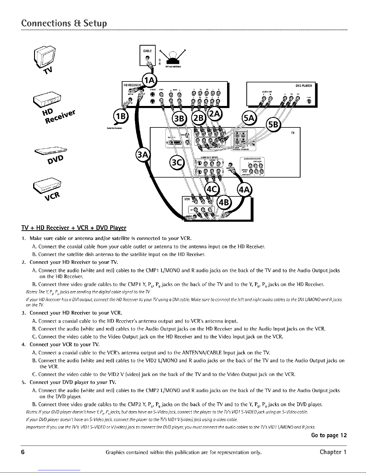
TV + HD Receiver + VCR + DVD Player
I. Make sure cable or antenna andJor satellite is connected to your VCR.
A. Connect the coaxial cable from your cable outlet or antenna to the antenna input on the HD Receiver.
B. Connect the satellite dish antenna to the satellite input on the HD Receiver.
2. Connect your HD Receiver to your'IV.
A. Connect the audio (white and red) cables to the CMPI L/MONO and R audio jacks on the back of the TV and to the Audio Output jacks
on the HD Receiver.
B. Connect three video grade cables to the CMP I Y, Ps, P_ jacks on the back of the TV and to the Y, P_, PRjacks on the HD Receiver.
Notes:TheY,P_P_jacksaresendingthedigital cablesignal tothe IV
If your HDReceiverhasa DVIoutput; connect theHDReceiverto your 1Vusing a DVIcable.Makesuretoconnect the left anddght audio cablesto rile DVIL/MONOandRjacks
on the iV
3. Connect your HD Receiver to your VCR.
A. Connect a coaxial cable to the HD Receiver's antenna output and to VCR's antenna input.
B. Connect the audio (white and red) cables to the Audio Output jacks on the HD Receiver and to the Audio Input jacks on the VCR.
C. Connect the video cable to the Video Output jack on the HD Receiver and to the Video Input jack on the VCR.
4. Connect your VCR to your TV.
A. Connect a coaxial cable to the VCR's antenna output and to the ANTENNA/CABLE lnput jack on the TV.
B. Connect the audio (white and red) cables to the VID2 LfMONO and R audio jacks on the back of the TV and to the Audio Output jacks on
the VCR.
C. Connect the video cable to the V1D2 V (video) jack on the back of the TV and to the Video Output jack on the VCR.
5. Connect your DVD player to your "IV.
A. Connect the audio (white and red) cables to the CMP2 L/MONO and R audio jacks on the back of the TV and to the Audio Output jacks
on the DVD player.
B. Connect three video grade cables to the CMP2 Y, P_, P_ jacks on the back of the TV and to the Y, P_, PRjacks on the DVD player.
Notes: If your DVDplayer doesn't have Y,P_,PRjaeks, but does have an S-Videojock, connect the player to the Iv's VID1S- VIDEOjack _lsing an S-Video cable
If your DVDplayer doesn't havean S-Videojack,connect the player to the W's VID1V[video/jack usingavideocable.
Importanz:If you usethe Iv's VID1S-VIDEOor V[videoJjack toconnect theDVDplayer,youmust connect theaudio cablesto the IV's VID1L/MONOendRjack£
Go to page 12
6 Graphics contained within this publication are for representation only. Chapter 1
Page 9
Connections Setup
L SATELLITE
RECEIVER
i
HDTVMONITOR
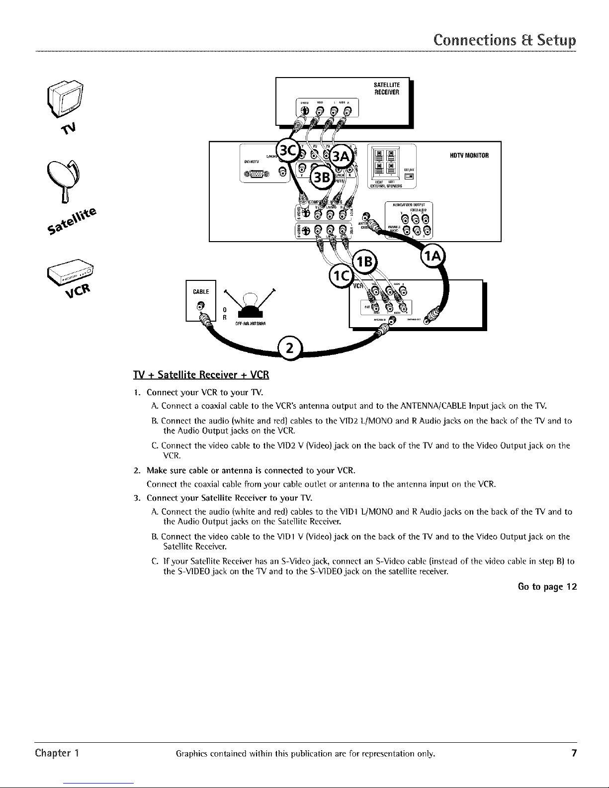
IV + Satellite Receiver + VCR
1. Connect your VCR to your TV.
A. Connect a coaxial cable to the VCR's antenna output and to the ANTENNA/CABLElnput jack on the TV.
B. Connect the audio (white and red) cables to the V1D2 L/MONO and R Audio jacks on the back of the TV and to
the Audio Output jacks on the VCR.
C. Connect the video cable to the VID2 V {Video)jack on the back of the TV and to the Video Output jack on the
VCR.
2. Make sure cable or antenna is connected to your VCR.
Connect the coaxial cable from your cable outlet or antenna to the antenna input on the VCR.
3. Connect your Satellite Receiver to your TV.
A. Connect the audio (white and red) cables to the V1D1 L/MONO and R Audio jacks on the back of the TV and to
the Audio Output jacks on the Satellite Receiver.
B. Connect the video cable to the VID1 V (Video) jack on the back of the TV and to the Video Output jack on the
Satellite Receiver.
C. If your Satellite Receiver has an S-Video jack, connect an S-Video cable (instead of the video cable in step B) to
the S-VIDEO jack on the TV and to the S-V1DEOjack on the satellite receiver.
Go to page 12
Chapter I Graphics contained within this publication are ['or representation only. 7
Page 10

Connections Setup
DVO Player
W + DVD + VCR
I. Cmmeet your DVD Player to your TV.
A. Connect the audio (white and red) cables to the CMP I LfMONO and R Audio jacks on the back o1 the TV and to
the Audio Output jacks on the DVD player.
B. Connect three video grade cables to the CMPI Y, P_, P_ jacks on the back of the TV and to the Y,P_, PRjacks on
the DVD player.
Notes:
IfyourOVOplayerdoesnothaveY,PB,Pjocks,butdoeshoveonS-Videojack,connecttheplayertotheVlOt 5-VlOEOjockontheWusingan
5-Videocable.
If yourDVDplayerdoesnothoveonS-Videojeck,connecttheplayertotheVIDI V(Video)jackonthebeckofthe1Vusingavideo¢oble.
Importont:If youusetheVIDtS-VIDEOorV(Video)jocktoconnectyour71/totheDVDpleyer,youmustconnecttheeudiocablestotheVID1
L/MONOendRjeckson theT_L
2. Cmmeet your VCR to your "IV.
A. Connect a coaxial cane to the VCR'santenna output and to the ANTENNA/CABLEInput jack on the TV.
B. Connect the audio (white and red) cables to the V1D2 L/MONO and R Audio jacks on the back of the TV and to
the Audio Output jacks on the VCR.
C. Connect the video cable to the V1D2 V (Video) jack on the back of the TV and to the Video Output jack on the
VCR.
3. Make sure cable or antem_a is connected to your VCR.
Connect the coaxial cable from your cable outlet or antenna to the antenna input on the VCR.
Go to page 12
8 Graphics contained within this publication are for representation only. Chapter 1
Page 11

Connections Setup
"IV+ A/V Receiver or Speakers
These are two different ways your TV uses a component to hear audio.
1. Connect audio cables to either the FIXED or VARIABLE AUDIO L and R OUTPUT jacks and to the Audio Inputs
on the A/V receiver.
* FIXED provides fixed-level audio output From the TV. This audio output is ideal |br connecting to an
A/V receiver that has its own volume control.
', VARIABLE provides variable-level audio output. Volume levels can be controlled by the volume
controls on the TV and TV remote control.
-OR-
2. Use speaker wire to connect the TV to external speakers.
" The EXT/INT switch beside the jacks let you turn the TV's internal speakers on or ofL lfyou connect
external speakers, slide the switch to EXT so the audio is sent to the external speakers only.
Choosing INT sends the audio to the TV's speakers only.
Note:Theexternalspeakerroringis8ohms with _5wettspower handling capabilities.
AN RECEIVER i
_,_ IN _A_ TV _R
[]
Connect to either FIXEDor
VARIABLEOutput
/
TV
Chapter 1 Graphics contained within this publication are For representation only. 9
Page 12

Connections 8: Setup
Explanation of Jacks
This section describesthe jacks you can useto make connections. There are severalways to connect components
to your TV.
DVI-HDTV L/MONO9
PB PR
COMPOXENTIXPUTS
COMPOSITEIXPUTS
V L/MONO R
r_ V L/MONO R )
UBWOOFER L R
EXT/INT
BIGItT LEFT
EXTERNAL SPEAKERS
DVI-HDTV Input Lets you connect an HD receiver with a DV1 output.
" DVI (Digital Visual Interface) Provides an uncompressed, digital video inter|_ce developed
|br high-bandwidth digital connection. It supports the overlay of high-resolution graphics
needed by some electronic program guide navigation and other interactive services. DVI,
when combined with HDCP (High bandwidth Digital Content Protection) technoloyy, creates
a protected digital connection. The signal speed of the DV1 connection is IO8Oi |br HDTV at a
rate of 1.78 Gigabits per second.
- L/MONa (Audio) Provides left audio connection when using the DV1 jack. The left audio
connector is usually white.
" R (Audio) Provides right audio connection when using the DV1jack. The right audio
connector is usually red.
No re: Remember to connect the left and righ t audio cables because the DVI cable carries only the picture signal,
not the sound.
COMPONENT INPUTS Lets you connect a component video source, such as a DVD player.
- CMP1 Y, PB, PR (Component Video) Provides optimum picture quality because the video is
separated into three signals. Use three video-grade cables for the connection. When using
CMPI Y,P_, PR,make sure to connect left and right audio cables to the CMPI L]MONO and R
Audio Input jacks.
* CMP1 L/MONa (Audio) Provides left audio connection. The left audio connector is usually
white.
CMP1 R (Audio) Provides right audio connection. The fight audio connector is usually red.
CMP2 Y, PB,PR,and L/MONa and R Audio Allows you to connect a second component
video source. Their description is the same as CMP1 above. When using CMP2 Y, PB, P_, make
sure you connect the left and right audio cables to the CMP2 Audio jacks.
COMPOSITE INPUTS Lets you connect another component such as a VCR, DVD player, or
laserdisc player. Its AUDIO jacks are the same as described Ibr CMPI above.
- V1D1 S-VIDEO Provides better picture quality than the video jacks (V1D1and 2 Video)
because the color part of the signal is separated from the black and white part of the picture.
When using VIDI S-VIDEO, make sure to connect left and right audio cables to the V1DI L[
MONa and R Audio Input jacks.
- V1D1 V [Video) Provides composite video connection. The video connector is usually yellow.
* V1D2 S-VIDEO, V and L]MONO and R Audio Allows you to connect a component such as
a VCR, DVD player, or laserdisc player. Their description is the same as V1DI above.
Note:DonotconnectonS-Videoend Videocableot thesame timeine_therVID1orVID2jacks.
AUDIO]VIDEO OUTPUTS Lets you connect an amplifier or audio receiver lbr improved sound
quality or an external video monitor.
* FIXED AUDIO L]R Provides fixed-level audio output from the TV. This audio output is ideal
lbr connecting to an A]V receiver when you want to control the volume through the A/V
receiver.
- VARIABLE AUDIO Provides variable-level audio output. Volume levels are controlled by the
volume controls on the TV and remote control.
- SUBWOOFER Provides lower bass audio frequencies out from the TV and to a subwoofer.
NOre.Ifyotl'veconnectedasubwoofer,makesure yousettheExternal5_lbwooferoption in the5ound menu.Goto
page22 forinstructions.
EXTERNAL SPEAKERS
- Right and Left Speaker Terminals Let you connect external left and right speakers to the
TV to receive left and right sound.
- EXT/1NT (switch) Lets you turn the TV's internal speakers on or offi EXT sends audio to
external speakers only. 1NT sends audio to the TV's internal speakers only.
ANTENNA]CABLE Lets you connect a coaxial cable to receive the signal from the antenna,
cable, cable box, or if using the examples on pages 6-8, a VCR.
10 Graphics contained within this publication are for representation only. Chapter 1
Page 13

Connections 8: Setup
The Front of Your IV
Front Inputs
The TV has front inputs for convenience: one set ofaudio/video inputs, an S-Video and a headphone jack. Locate the jacks either
on the front of the TV or on one of the sides. You can access the component you connected to the front of the TV by pressing the
INPUT button on your remote until FRNT appears on the screen. The jacks are ideal lbr using a video game console or a
camcordeL
Note:Whenconnectingadevicethat usesamonauralcable,suchassome comcorders,use theLeft(mona) inputjock toget soundfrom bothspeakers.
PHONES Allows you to connect headphones to listen to the sound coming from the TV. To adjust volume control of the
headphones, press the VOL > or VOL < button (the volume display appears). Press the arrow up or down button (the headphone
volume display appears), then press the right or leIl arrow button to adjust the headphone volume.
VIDEO (in) Receives video from another component such as a VCR,camcorder or video game console.
L/MONO and R AUDIO Receives audio from another component such as a VCR, camcorder or video game console.
S-VIDEO (in) Allows you to connect an S-Video cable from another component. Make sure you also connect audio cables from
the component to the TV.
Front Panel Buttons
If you cannot locate your remote, you can use the |?ant panel buttons of your TV to operate many of the TV's |_atures.
MENU/OK Brings up the Main menu. In the menu system, it selects highlighted items.
CH v Scans down through the current channel list. In the menu system, acts like down arrow button on the remote control and
adjusts menu controls.
CH _. Scans up through the channel list. In the menu system, acts like up arrow button on the remote control and adjusts menu
controls.
VOL < Decreases the volume. In the menu system, acts like left arrow button on the remote control and adjusts menu controls.
VOL > Increases the volume. In the menu system, acts like right arrow button on the remote control and adjusts menu controls.
POWER Turns the TV on and off.
Plug in the IV
Plug the end of the power cord into a grounded
..... ]
o /
G"<TZ Arro.,,
Tip
Toaccessthesetup menus manually, press
MENUandchooseSETUe
wall outlet. Insert the plug completely into the outlet.
Put batteries in the remote
• Remove the battery compartment cover From the back of the remote by pushing down on and
sliding off the cover.
• Insert 2 "AA" flesh batteries. Make sure the polarities (+ and -) are aligned correctly.
• Replace the coveL
How to Use the Remote Control to Complete the Initial Setup
The technical term is "Navigation" - how you move through the on-screen menus. The theory is
the same throughout the menu screens: highlight your choice and select it.
To highlight a menu item, press the arrow buttons on the remote to highlight one of the items
listed on the screen. Use the up or down arrow button to move up or down. Use the right or left
arrow button to move right or left.
To select the item that you've highlighted, press OK.
Note:Highlightedmeansthatthemenuitemstandsoutfromothermenuitemsonthehst(appearsdarker,brighter,
oradifferentcolor).
Turn on the IV
PressTV on the remote, or pressPOWERon the TV's front panel.
Note: Pressing the TVbutton not only turns on the ]V,,hut puts the remote into TVmode. "IV mode" means that the
buttonsontheremotecontroloperate theTV'shmctions.
Complete the Initial Setup
The menu system in your TV allows the TV's |i?atures to work properly. The first time you turn on
your TV, the setup screens appeal
Chapter 1 Graphics contained within this publication are for representation only. 1 1
Page 14

Connections 8: Setup
Set the Menu Language
The first part of the setup allows you to select your preferred language For the menu system.
I. Highlight your preferred language |br the menu system using the arrow buttons.
2. Press OK to select that language (the Channel Setup screen appears with Autochannel
search highlighted).
Complete Auto Channel Search
This part of the setup allows the TV to search |br all channels viewable through your antenna
or cable TV system. This is sometimes called auto programming. Press OK to begin auto
channel search. When the channel search is complete, you can either press OK to access the
List PcLabels screen or CLEARto view TV.
Note for models D40W20 and D52 W20: If you press CLEARthe Auto Convergence screen appears.
Changing Lists and Labels
The List _ Labels part of the setup lets you edit your channel list and choose or create a
personal six-character label For each channel.
Note:ChangingListand Labelscanbetimeconsuming. Youcan change theseat o ]atar timeby accessingthe
Setup menu.
1. Press the left or right arrow to scroll through the available channels and choose the
channel you want to edit.
2. Press the down arrow to highlight the In channe! list option. Press the le|l or fight arrow
button to add (the box is checked) or remove (the box is unchecked) the channel from the
list.
3.
Press the down arrow to highlight the Channellabel option. Press the left or right arrow
button to scroll through the available list of 25 most common labels. The last option in
the list allows you to create your own six-character label For the channel (the first letter oF
the label is highlighted).
4. Press the 1 or 2 number button to change the first letter of the label.
5. Press the right arrow to highlight the second letter, then press the I or 2 number button
to change the second letter, etc...
6. When you are finished creating your label, press OK. For model D34W20, your TV tunes to
the last channel available in your channel list. For models D4OW20 and D52W20 only, the
Auto Convergence menu appears next.
Auto Convergence (for models D40W20 and D52W20 only)
Your TV's picture tubes might have been disturbed during delivery or after you moved the TV,
causing the color in your TV to be out of alignment. The colors adjust by starting auto
convergence.
1. Press OK to begin auto convergence.
2. When the auto convergence is complete, the Redcenter convergence menu appears. The
cross in the middle of the screen should be yellow. If it is not, use the arrow buttons to
move the red cross to overlap the green cross. Press OK when adjustments are complete.
3. The Blue center convergence menu appears with a eyan cross in the middle of the screen. If
it is not, use the arrow buttons to move the blue cross to overlap the green cross. Press OK
(the TV tunes to the last available channel in the channel list).
12 Graphics contained within this publication are For representation only. Chapter 1
Page 15

Using the Remote Cor tro[
Indicator
VCRF ON.OFF TV
DVD VCR2 AU× SAT.CABLE
_WUl_ SKIP
GO BACK
[NFO
MENU CLEAR
,O 20
40 50 °O
,0 BO,CD
INPUT SOUND.ANT
©o
REVERSE PLAY FORWARD
RECORD STOP PAUSE
PFP SWAP CH - CH *
0000
NoteTheVCR1,DVO,VCR2,andSAT.CABLEbuttons
alsoturnonmostRCA,GE, andProscanproducts.
The Buttons on the Remote Control
(0-9) Number Buttons Enter channel numbers and time settings directly through the remote
control
Toenter a one-digit channel, enter a zero first. To enter a two-digit channel, pressthe two digits.
Toenter a three-digit channel, pressand hold the "1" button until "1" and two dashes[- -)
appear,then add the secondtwo digits, Example:to tune to channel 123, pressand hold 1 until
"1- -" appears,releasethe 1 button and then press2and 3.
Arrows Usedto point to different items in the IV menu and to adjust the menu controls.
Movesthe PIPwindow when no menusareon the screen,Also switches the two POPwindows
when no menusare on the screen,ForZoom use,go to next page.
AUX Puts the remote in AUX mode,Canalso be programmed to operate most brands of an
additional remote-controllable component,
gacklight Lights up someof the buttons in the dark.
CH + or CH- Scansup or down through the current channel list. Pressonce to change the
channel up or down; pressand hold to continue changing channels,
CH+ or CH- PiP When using PIPor POP,changes the channel inthe picture window.
CLEAR Removesany menu or display from the screenand returns you to normal viewing,
DISC MENU No function available in IV mode, If operating an RCA,a GEor ProseanDVDplayer,
for example, brings up the Disc menu,
DVD Putsthe remote in DVDmodeand, if Autotuning isenabled, will turn on the IV and tune to
the correct input channel.
FREEZE When watching IV, freezes the picture until you press another button to resume
normal IV viewing.
Note:Donotuset_c"Freezet_at_refor ane,_tendedperiodofUrneThiscancausetheimageto bepermanently
¢mpfintvdont#c"picture"tube'.Suchdamage.isnotco_,eredbyyourwarrantg Pressanybuttontounfreezet#e
pictureatanyt_rne
GOBACK Returns you to the previous channel
GUIDE Bringsup the Channel Guidemenu.
INDICATOR Indicates the programming mode when programming the remote to control
components.
INFO Bringsup status display; pressagain to clearthe screen,
INPUT Pressto toggle through the available input sources (VlD1,VlD2, FRNT,CMP1,CMP2 and
DVLPressthe CH+or CH- button to resumeIV viewing).
MENU Bringsup the Main menu.
MUTE Reducesthe IV_svolume to its minimum level. Pressagain to restore the volume.
OK/FREEZE When in the menu system, selects highlighted items. When watching IV, freezes
the picture until you press another button to resume normal IV viewing.
ONoOFF When in IV mode,turns the IV on and off. lf in another device mode (VCR,DVD,
SAT.CABLE,etc.) and programmed, will turn the device on and off.
PIP Pressonceto bring up the small picture-in-picture window. Pressagain to bring up the
picture-outside-picture (POP)windows, Pressto remove POP,(SeeChapter3 for more
information about using PIP,)
Tip
Toturn off adtheRCA,GF,andProseancomponents that
are connected to the T_,pressON.OFFtwice within two
seconds.
Thisfeature only works with most RCA,GE,andProscan
products.
REVERSE,PLAY,FORWARD,RECORD,STOP,PAUSE If programmed,provides transport control
for some remote-controllable VCRs,DVDpiayera,laserdiscplayers,tape decks,and CDplayers,
SAToCABLE Putsthe remote in SAT.CABLEmodeand, if Autotuning is enabled,will turn on
the IV and tune to the correct input channel,
SKIP Pressonce before changing channels and theIV wiil wait 30 secondsbefore returning
you to the original channel Pressrepeatedly to addmore time,
SOUND-ANT Displaysthe Picture andSound presetsettings at the bottom of the IV.
SWAP When using PiP,swapsthe main picture with the PiPwindow. When using POP,swaps
the left and right pictures,
TV Turnson the IV and putsthe remote in IV mode. Alsodisplays current status,
Graphicscontained within this publication are Forrepresentation anlg 13
Page 16

Using th( Remot Control
VCR1 Puts the remote in VCR1 mode and, if Autotuning is enabled, will turn on the TV and tune to the correct
input channel
VCR2 Puts the remote in VCR2 mode and, if Autotuning is enabled, wii[ turn on the TV and tune to the correct
input channel
VOL - or VOL + Decreases or increases the IV's volume,
ZOOM+ or ZOOM- When watching IV, changesthe current format of the screen(4x3,Zoom 1419,Zoom 1619,
Zoom 16/9 _Iv,Cinerama,regular mode 1619).
Using the INPUT Button
Usethe INPUTbutton to scroll through the available input channels and view components you have connected to
the IV.
I. PressIV to place the remote in IV mode. Make surethe component you want to view isturned ON.
2. PressINPUTto tune to an available input channel.
3. To return to the channel you were previously watching on IV, pressCH+or CH- button,
VCR1 ON= OFF TV •
_VD VCff2 AUX SAT=CABLE
Indicator
_EVE_SEPLaY
You'llusethesebuttons whenyouprogram
theremote.
#nportunbTheremote,maynot hecompatiblewith eft
modelsof ull brandsof components,it ol5omuy not
operuteaftfunctions of theremotethut came with
yourcomponenL
Tip
Tostop theuutomatic code3eurchwithout programming
any components, pressand hold CLEARuntit the indicator
onthe remote turnsoff.
Programming the Remote to Operate Other Components
The universal remote can be programmed to operate most brands of remote controllable
components. The remote is already programmed to operate most RCA, GE, and Proscan
components.
Also, the AUX button can be programmed to operate most brands of an additional remote-
controllable component,
Note:TheIVbutton can't beprogrummedon thisremote,.
Find Out If You Need to Program the Remote
To determine whether the universal remote needs to be programmed for your component, turn
the component ON. For example, to program the remote for a VCR, turn on the VCR. Point the
remote at the VCR, and press the VCR1 button, Then press ON,OFF or CH + (channel up] or CH -
(channel down) to see if the VCR responds to the remote commands, If the component does not
respond, the remote needs to be programmed,
Programming the Remote
Therearetwo ways to program the remote controh
automatic code search
direct entry
Using Automatic Code Search
The following instructions can be used to program the remote to operate each of your
components. If you want to stop the automatic code search without programming any of your
components, press CLEAR until the indicator on the remote turns off.
I. Turn on the component you want to operate (VCR, DVD player, eta,)
2. Press and hold the component button you want to program (VCR1, DVD, eta,), While holding
the component button, press and hold ON,OFF until the indicator on the remote turns on,
then release both buttons,
3.
Point the remote at the component. Press and release PLAY, then wait 5 seconds or until the
indicator on the remote stops flashing,
At this point the remote is searching for the correct code to program. If, after 5 seconds, the
component you want to operate does not turn off, press PLAY again to tell the remote to
search the next set of codes.
Continue pressing PLAY until the component turns oft or you have searched through all of
the codes. There are 20 total sets of codes, If the component does not turn off after pressing
PLAY 20 times, then the remote can't be programmed to operate that component,
If the component you want to control does turn off:
I. Press and release REVERSE,then wait 2 seconds, Repeat this step until the device turns back
ON.
2. To finish, press and hold STOP until the indicator on the remote turns off,
14 Graphicsconfined within this publication ore for representation only. Cha_te_" 2
Page 17

Usi 9 the Remote Co tro[
Important
You must continue pressing the component button while
you enter thecode.
Let'ssay you hoveeZenith VCR.To program the universal
remoteto operate the VCR,youwould:
Pressend hold the VCRI button while youenter thefirst
codelisted forZenffh in the VCRCodescolumn.
ReleasetheVCR1button.PressON,OFF to seeiftheVCR
responds,tf it doesn't, follow the samesteps, but enter the
secondcodefor Zenith VCRsin_teadof the first.
Note
Some of the female's buttons might operatedifferently for
other components,especiallywhen you're usinganother
component'_menusystem.
UsingDirectEntry
I. Turn on the component to be programmed,
2. Lookup the brand and code number[s)Forthe component on the code list in this section,
3. Point the remote at the component.
4. Pressand hold the component button you want to program on the remote.
5. Enterthe 4-digit code from the remote control code list on the following pages.IFthe
indicator flashes,you have either entered an invalid code or the button isn't programmable.
6. Releasethe component button, and then pressON.0FF to seeif the component respondsto
the command, If it doesn't, try pressingthe component button and then ON.OFFagain.
• IFyou get no response,repeat these steps using the next code listed Foryour brand, until the
component respondsto the remote commands,
• If you try a[[the codesfor your component brandand none work, try the automatic code
searchmethod, If automatic code 5earth doesn't find the code,the remote isnot compatible
with your component.
How to Use the Remote After You've Programmed It
Becausethis universal remote can control several different components (W, DVD,VCR,satellite
receiver,etc,) it usesoperational modestriggered by the component buttons. For example, iFyou
want the remote to control the IV, you would pressthe IV button to put the remote into IV
mode beforeyou could control the IV.
I. Pressthe appropriate component button {OVD,IV, VCR1,VCR2,SAT.CABLE,AUX) to setthe
remote to control the component,
2. PressON.0FF to turn the component ON or 0FE
3. Usethe remote buttons that apply to that component,
Notes:
Theremote maynotbecompatibk"with oil brandsandmode,Is ofcomponents. It alsomaynot
operatea]]functions of the r_motethat camewith yourcomponentL
Ifyou k_p pressingbuttons and nothing happcns,_c remote _ probabJym the wrong mode.You
mustpressthe componentbu_on that match_ thecomponent you wantto operate _ _, ff you want
to operatethe VCR,pressVCRt on ther_motecontrol toput the remote mVCRmod_.]
Remote Control Codes
VCRCodes
Programmable for VCR1, VCR2, and AUX
buttons,
,_JmJral .............................................................................. 2132
Advemu_ ........................................................................... 2026
Aiko .................................................................................... 2027
Aiw_ ................................................................................... 2026
Akal ...........2003, 2004, 200S, 20(}7, 200B, 2111, 2112, 2113
Am_d_an High .................................................................. 2021
Asha ................................................................................... 2013
Audio Dynamics .................................................... 2009, 2010
Audiov_ ........................................................................... 2014
B_] _ Howell ..................................................................... 201l
Bt_a_tmark ........................................................................... 2013
Broksonic ................................................................ 2012, 2025
Cali_ ................................................................................... 2014
Cand]_ ............................................... 2013, 2014, 20t5, 2016,
....................................................................... 20t 7, 2018, 2019
(anon ............................................................ 2021, 2022, 2114
( ap(hart ................................................................... 2020, 2110
( arvt'r ................................................................................. 2062
((E .......................................................................... 2027, 2061
Ci+Jz_n.................................................................... 2013, 2014,
....................................... 2015, 2016, 2017, 20tB_ 2019, 2027
( olortyme .......................................................................... 2009
(o]t ..................................................................................... 2061
( rai&_................................................... 20to, 2014, 2023, 2061
Cm_is-Mafhes ............................................. 2000, 2009, 2013,
............................. 2016, 2018_ 2021, 2022, 2024, 2115_2131
Cybernex ........................................................................... 2013
Dot,woo .,.,,. 2015, 2017, 2019, 2025, 2026, 2027, 2028, 2It0
Daytmn ................................................................................. 2110
DBX ............................................................................ 2009, 2010
Dimensia .................................................................... 2000, 2131
Dyna_ch .............................................................................. 2026
Electmhome ............................................................. 2014, 2029
Electrophoni_ ...................................................................... 2014
Emerson ......................... 20t 2_ 2014_ 2015, 2021_ 2024_ 2025_
.......... 2026, 2029, 2030, 2031. 2032, 2033_ 2034_2035_
2016_ .......... 2037, 203a, 2039, 2040, 204L 2042,2044_
2045_ 2046 ............................................. 2047, 2065_ 211a_
2116, 2117, 2130
Fisher ......... 2011, 2023, 204B, 2049, 2050, 2051, 2052, 211B
Ft!ji ............................................................................. 2021, 2119
Fuuai .................................................................................... 2026
GmTard ................................................................................. 2026
GE ................................................................... 2000, 2001, 2013,
......................................... 2021, 2022, 2053, 2115, 2120, 2131
Gold.tar ............................................... 2009, 2014_ 2018, 2054
Gradiente ............................................................................. 2026
Ha_ley Davk]so_ ................................................................. 2026
Harmon KmxJon .................................................................. 2009
Ha_vood .............................................................................. 2061
H_*adqum_e_ .......................................................................... 201 ]
Hkaehi ..................................................................... 2055_ 2056,
..................................................... 2057, 2107, 211L 2120, 2122
H[_0 ...................................................................................... 2023
Instant Rt'_l_y ..................................................................... 202]
JCL ........................................................................................ 202]
Je Ptmnt'y ............................................ 2009, 20]0. 2011, 2013,
.................................................. 2014. 202L 2022, 2055, 2056_
.................................................... 205a, 2059, 2060, 2]07, 2]]8
Jensm] ............................................................. 2ass, 2056, 21]]
JVC ................................... 2009, 2010, 2OH, 20]8, 2]]], 212S
K_uwood ................ 2009, 20]0, 2011, 2016, 2018, 2]]], 212S
KLH ....................................................................................... 2061
Kodak ................................................................. 2014_ 202]
Lloyd ............................................................................ 2026
Loglk ............................................................................ 2061
LXI ................................................................................ 2014
Magnav_n ............................................. 2021, 2022, 2062,
............................................ 2063_ 2104, 2105, 2108, 2124
Magnin ......................................................................... 2013
M_antz ..,.,,., 200a, 2010, 2011, 2016, 2018, 2021, 2062,
2064
Marta ............................................................................ 2014
Masushlta .................................................................... 2021
Me[ ............................................................................... 2021
Memorex ,,.,,, 20]], 2013, 2014, 2021, 2023, 2026, 2104,
2132
MGA ........................................................ 2029, 2065, 2113
MGN Tet'hnelogy ........................................................ 2013
Midland ........................................................................ 2053
Mino]t_ ................................................... 2055, 2056, 2107
Mit_ffbishi., 2029, 2055, 2056, 2065, 2066, 2067, 2068,
, 2068, 207(L 2071, 2072, 207a, 2074, 2106, 2113, 2123
Mo_t_onl_y Wa_'d ........................................... 2075. 2132
Motorola ............................................................ 202L 2132
MTC .................................................................... 20t 3, 2126
Mu]titech ........................... 2013, 2016, 2026) 2053, 2061
NEC ...................................... 2009, 20KL 2011,2016, 2018,
.................................. 2064, 2076, 2078, 2079, 2111, 2123
Nikko ............................................................................ 2014
Noblex .......................................................................... 2013
Olympt_s ....................................................................... 2021
Oprim_s .............................................................. 2014, 2132
Oproui_a ...................................................................... 2096
Panasonk' ............... 2021, 2022, 2109, 2125, 2126, 2127
Pentax ................................ 2016, 2055, 2056, 2107, 2120
Pent_'_ Rc_;t'a rch .......................................................... 20] a
Phi]co ........................................... 2021, 2022, 2062, 2063
Fhi]ips .......................................... 2021, 2062, 2096, 2124
Graphicsconfined within this publication are for representation onl)z 15
Page 18

Using the Remote Control
VCRCodescontinued
Pilot ............................................................................. 2014
Pioneer ............................. 201_ 2055, 2(180, 2081, 2123
Por0and ....................................... 2016, 2017, 2019, 2110
Proscan .................................................. 200_ 2(101, 2131
Pmtec .......................................................................... 2061
Pulsar .......................................................................... 2104
Quarier .................. 2011
Quariz ................... 2011
Qua_ar ................................................... 2021, 2022, 2125
RCA ........... 200_ 2001, 201)3, 2013, 2021, 2055, 2056,
....... 2082, 2083, 2084, 2085, 2086, 2087, 2088_ 2089_
............ 2090, 2091, 2107, 2115, 2120_ 2125, 2131, 2133
Radioshack]Realisgc ................. 2011, 2013, 2014, 2021,
......... 2022, 2023, 2026, 2029, 2049, 2050, 2096, 2132
Radi_ ........................................................................... 2014
Rand_x ........................................................................ 2014
Ricoh ........................................................................... 2128
Run_o .......................................................................... 2104
Sanlsung ................ 2005, 2013, 2015, 2033, 2053, 2112
Sa21ky ................................................................ 2104, 21"32
Sansul .......................................... 2010, 2092, 2iii, 2123
SaJ_yo ..................................................... 2011, 2013, 2023
SCOtt, 2012, 2015, 2025, 2032, 2038, 2065, 2093, 2116
Seam ................................. 201i, 2014, 2021, 2023, 2048,
.................... 2049, 2050, 2051, 2055, 2056, 2107, 2118
Sharp .......... 2017, 2020, 2094, 2095, 2096, 2097, 2132
Shintffm ..................................... 2004, 2056, 2061, 2098
Shogun ........................................................................ 2013
S[gn;41_t_ _ .................................................................... 2132
Singer ..................................................... 2021, 2061, 2128
Sony ............................................ 200& 2098, 2099, 2110
STS .................................................................... 2021, 2107
Syb/anla ..,. 2021, 2022, 2026, 2062, 2063, 2065, 2124
Symphonic ................................................................. 2026
Tandy .......................................................................... 2011
Tashiko ........................................................................ 2014
Tamng .......................................................................... 2111
T£AC ...................................................... 2026, 2085, 2111
Tcch nk_ ............................................................ 202i, 2109
Teknika ............................. 2014, 2021, 2026, 2100, 2129
TMK ....................................................... 20i3, 2024, 2047
Toshiba.,.,,.,. 2015, 2049, 2051, 2055, 2065, 2093, 2116
Totcvsion ......................................................... 2013, 2014
Unltech ........................................................................ 2013
Vector Rc_;ca rtSl ......................... 2009, 2010, 2015, 2016
Victor .......................................................................... 2010
Vid(_o ConcepL_ ................ 2009, 2010, 2015, 20i6, 2113
Vid('osonic .................................................................. 2013
_'aJxls ......................................... 2013, 2014, 2015, 2021,
............................. 2023, 2026, 2029, 2055, 2056, 2061,
...................... 2096, 2101, 2102, 2103, 2107, 2116, 2132
XR-1000 ............................................... 2021, 2026, 2061
Yamaha .............................. 2009, 2010, 2011, 2018, 2111
Zeni01 ................................ 2004, 2098, 2104, 2ii9, 2128
Satellite Receiver Codes
Programmablefor SAT,CABLEand AUX
buttons,
Alphastar .................................................................... 5W9
Chapparal ........................................................ 9056, 5057
Dishnet ........................................................................ 5078
DT_ke ................................................................ 5058, 5059
Echostar ...................................................................... 5089
GE ..................................................................... 5000, 5001
General Instrunlcnt_ ............................ 5060, 5061, 5062
Hitavhi ............................................................. 5083, 5084
Hughes ............................................................. 5077, 5090
JVC .............................................................................. 5082
Panasoni_ ................................................................... 5075
Phi[ips ......................................................................... 5085
Prlmc,_tar .................................................................... 5076
Proscan ............................................................ 5000, 5001
RCA .................................. 5000, 5001, 5071, 5080, 5081
Realistic ...................................................................... 5063
Sony ............................................................................ 5072
STS 1 ............................................................................ 50_I
STS2 ............................................................................ 5065
STS3 ............................................................................ 5066
STS4 ............................................................................ 5067
Toshiba ............................................................. 5068, 5073
Uniden ............................................................. 5069, 5086
CableBox Codes
Programmablefor SAT,CABLEand AUX buttons.
ABC ........................................... 5002, 5003, 5004, 5006, 5053
Amronix ................................................................... 5008, 5009
Archer ............................................................. 5008, 5009, 5010
Cabletcnn_ ........................................................................... 500B
Cableview ............................................................................ 500B
Colour V_c .............................................................. 5012, 5013
Comtmnk_ .......................................................................... 5014
Cont¢c .................................................................................. 5016
Eastern ................................................................................. 5017
GC Elcct;onics ..................................................................... 5009
GE .............................................................................. 5000, 5001
Gcm_ni ....................................................................... 5018, 5019
Gcm'ral Instrument ............................................................ 5003
Haml_n ........................... 5020, 5021, 5022, 5028, 5035, 5045
Hitachi ................................................................................. 5003
J_n"61d............................ 5003, 5018, 5023, 5024, 5046, 5053
Magnav_ ........................................................................... 5025
Memorex .............................................................................. 5026
Movie Tim_ ......................................................................... 5027
NEC ....................................................................................... 5005
NSC ....................................................................................... 5027
Oak ............................................................................ 5016, 5029
Panaso nk' ................................................................ 5048, 5052
Philips ........................................ 5011, 5012, 5013,5015, 5019,
..................................................... 5025, 5030, 5031, 5032
Pioneer ...................................................................... 5033, 5094
Prosca_ ..................................................................... 5000, 5001
R(A ...................................................... 500?, 5047, 5049, 5052
Realistic ............................................................................... 5009
Regal ......................................................................... 5022, 5035
Regency ............................................................................... 5017
Rembrandt ........................................................................... 5003
Samsung .............................................................................. 5034
Scien+Jfic Atlanta ............................... 501)6, 5036, 5037, 5038
Signal ................................................................................... 5018
Signature ............................................................................. 5003
Spmcer ................................................................................. 5052
Standard Component_ ............................................. 5039, 5044
Stan_om ..................................................................... 5018_ 5053
Stargate ................................................................................ 5018
Starqttest .............................................................................. 5018
Tocom ....................................................................... 5004_ 5023
Tusa ...................................................................................... 5018
TVB6 ..................................................................................... 5027
Unika ......................................................................... 5008, 5009
Unit_-d (able ........................................................................ 5053
Univcr_al ......................................................... 5008, 5009, 5010
Vie, vsta r .................................................................... 5025, 5027
Zenith ........................................................................ 5050, 5051
DVDcodes
Programmablefor DVDand AUX buttons.
Aiwa ..................................................................................... 3009
GE ......................................................................................... 3000
Hitachi ................................................................................. 3008
JVC ............................................................................. 3002, 3010
Konka ......................................................................... 3011, 3012
Magnav_ ........................................................................... 3003
MiL_ublshi ............................................................................ 3004
Panasonk' ............................................................................ 3013
Ehilips .................................................. 3003, 3019, 3021, 3022
Pioneer ................................................................................. 3005
Proscall ................................................................................ 3000
R(A ........................................................................... 3000, 3001
Sanyo ................................................................................... 3014
So ny ................................................................ 3006, 3015, 3016
Toshiba ............................................................ 3007, 3017, 3020
Zenith ................................................................................... 30i8
Audio Codes
Programmablefor the AUX button only.
RCA and Dimensia
AM/FM .......................................................... 4003, 4270
AUX .......................................................................... 4004
P6ono ....................................................................... 4005
Tape........................................................................... 4006
('D ......................................................... 4007_ 4190, 4211
Rereiv_rs
Aiwa ............................................ 4261, 4262, 4263, 4264,
....................................................... 4265, 4266, 4267, 4277
Denon ............................................................................. 428t
Harman Kardon ............................................................ 4276
JVC ................................................................................. 4268
JVL ................................................................................. 4276
Kenwood ........................................................................ 4269
0nkyo ............................................................................. 4278
0p+J m_s .......................................................................... 4284
Pa nasoni¢ ........................................................... 4279, 42B0
Pioneer ........................................................................... 4275
RCA ................................................................................ 4270
Shet_vood ....................................................................... 4282
Sony .......................................................... 4271, 4272, 4281
Tcch nk%, .............................................................. 4279, 4280
Wm"ds ............................................................................. 4275
Yamaha ............................................................... 4274. 4275
CD Players
ADC .......................................................... 4200, 4201, 4220
Aiwa .................................................................... 4175, 4203
Akai ................................................................................ 4205
Denon ............................................................................. 4208
Dyn;_tech ........................................................................ 4177
En]erson ......................................................................... 417B
Hsh_r ........................................................ 4179, 4212, 4213
GE ................................................................................... ¢216
Hitachi ........................................................................... 4180
JVC ....................................................................... 418L 422]
Ke_wood .................................................. 4183, 4222, 4224
Luxman .......................................................................... 4225
Marantz ............................................................... 4185, 4226
Mgs_Jbishi ........................................................... 4229, 4230
MCS ................................................................................ 4228
Nak_n]ich_ .......................................................... 4232, 4233
NEC ................................................................................. 41 B4
0nkyo ....................................................... 41B6, 4234, 4235
0p+J m_s .................................................... 4237, 4238, 4239
Panasoni£ ...................................................................... 41B8
Pioneer ................................................................ 4189, 4240
RCA ...................................................................... 4190, 4211
SanyO ............................................................................. 4250
Seat's ............................................................................... 4207
Shet_vood ....................................................................... 4243
Sony ......................................................... 4195, 4209, 4244
Tvac .......................................................... 4245, 4246, 4247
Tvch nk',_ ......................................................................... 4197
Toshiba ........................................................................... 4231
Yamaha .................................................... 4198, 4199. 4241t
16 Graphicsoontained within this publication areForrepresentation onl_ Chapter 2
Page 19

Sample displays on a Channel Banner.
Using the TV's Features
Channel Banner
Thereareseveralindicators that might appear when you pressthe tV or INFObuttons on the
remote. Thisdisplay is called the Channel Banner.Thefollowing list describesthe items on the
Channel Bannerscreen (left to right and top to bottom),
4/3 format
Mono
/orStereo)
SAP
CC
03:45 pm
15NBC
Commercial
skip 0:30
Displaysthe current screenformat,
Mono displayed when the current channel is broadcasting in mono.
Stereo displayed when the current channel isbroadcasting in stereo,
Displayedwhen the current channel is broadcasting SAP[SecondAudio
Program)information,
Displayedwhen the Parental Controls are locked.
Displayedwhen ClosedCaptioning is availableon the current channel.
Displaysthe current time,
Displaysthe current channel and label assignedto the channel,
Displayedto count time remaining on the commercial skip (SKIP)timer.
Displayed when you mute the sound,
With the autatuning feature, you can set up the TV
to tune to the channel you need to watch by
pressing that eomponent's button,
Why You Should Use the Autotuning Feature
Theautotuning feature automatically tunes the IV to the correct channel for different
components you have connected to your IV (like aVCR,DVDPlayer,etc,) When you set up
autotuning in the menu systemyou don't haveto rememberto change your IV to channel 3, for
example,when you want to watch the tape in your VCR,
How to Set Up the Autotuning Feature
The way you set up the autotuning feature in the IV's menu corresponds to the component
buttons on the remote and the way you have each component connected to your IV. When you
set up autotuning, you're telling the IV what channel to tune to when you press the VCR1, VCR2,
DVD, or SAT_CABLE button on the remote control,
1, PressMENU (the MAIN MENU appears),
2, Highlight Setupand pressOKon your remote control.
3, Nighlight Autotuning and pressOK,
4, Choosewhich channel you would like to set:
Set VCRI Channel Letsyou set up the channel the IV tunes to when you pressthe VCR1button,
Set VCR2 Channel Letsyou set up the channel the IV tunes to when you pressthe VCR2button,
Set DVDChannel lets you set up the channel the IV tunes to when you pressthe DVDbutton,
5etSAT/Cobtechonnel tots you set up the channel the IV tunes to when you pressthe SAT*CABLEbutton on
an RCAsatelNte receiver remote, [TheRCADTCIOOHD receiverisconsidered a satellite device andcan beset up
for autotuning usingthis channel.)
5, Pressthe right arrow button to selectthe choice that matchesthe way you have the component connected to
this IV, and pressOK.
Thechoices and a brief explanation follow:
NiA Choose this if you don't havethis particular component connected to the IV, or if you don't
want the IV to automatically tune to the correct channel when you're using this component,
Channel3 or4 Component is connected to the CABLE/ANTENNAjack on the back of the IV, and
you want the IV to tune to channel 3 when you pressthe corresponding button on the remote.
Reminder: make sure the component's Channel 3/4 switch is set to channel 3.
VfD1or VID2(VideoInput) Component is connected to aVIDEOor S-Videojack on the backof
the IV and you want the IV to tune to a VlD input channel when you pressthe corresponding
button.
FRNT(FrontVideoInput) Component isconnected to the VIDEOjack on the front of the IV and
you want the IV to tune to the front VlD input channel (FRNT)whenyou pressthe corresponding
button.
O_e_" 3 Graphics contained within this publication are for representation only. 17
Page 20

Using th( TV% Featur ;s
CMP1orCMP2(ComponentVideoInput) Compatible component video source,such as a DVDplayer or digital W converter box, is
connected to the three COMPONENTVIDEOINPUTjacks (Y,PB,PR)on the back of the IV and you want the IV to tune to the component
video input channel (CMP)when you pressthe corresponding button.
DVl Component is connectedto the DVI-HDCPjack on the back of the IV and you want the IV to tune to the DVIinput channel when
you pressthe corresponding button,
Parental Controls and V-Chip
Thefirst three choices inthe ParentalControls menu involvesoftware insideyour IV (referred to asV-Chip) which allows you to block
IV programs and movies basedon violence, sex,or other content you may believe children should not view.
Onceyou block programs,you can unbIock programsby entering a password.
Bydefault, the software inside your IV is turned "off."
Nut_.Por_,nt_lControls_._in_sarenot_v_flobl__furDVI,CMP1orCMP2mput_
How V-Chip Works
V-Chip readsthe program's age-basedrating [IV-MA, IV-14, etc,) andcontent themes [(Violence (V), Adult Language (1),etc,)]. If you
haveblocked the rating and/or content themes that the program contains, you will receivethe messageThischannelis not approvedfor
v_e wing.
Broadcastersare not required to provide content themes,so programs receivedwith no content themes wii[ only be blockedif you
block their age-basedrating. You canalso block out programs that have beengiven a rating of"Not Rated,"and programs that are
considered "unrated." TheIV age-basedratings and content themes you can block are listed in the following table,
Age_BasedRating Descriptionand Content Themesfor Age=Based Ratings
W-MA Mature Audience Only. SpecifiCaIV:,,designed to beviewed by adults and may be unsuitable for children under17, it Contains
One0r more Ofthe following content themesl Crudeindecent language(E), explicit sexua!activity (s)4or graphic viol_:nce[v)
ParentsStrongly CaUtioned.COntainssome material that many parents would find Unsuitablefor ChildrenUnder14 Parents
TV-14 arestrongly urgedto eXbrciseg_eater Carein monitoring this program and are Cautioned against Ibtting childrbn undbr the
ageof 14 watch unattended. Thisprogram COntainsOneor moreof the following COntentthembs: intebse!y suggestive
dialogue (D) strong coarselanguage ([) intenseSexualsituations [S) OrintenseViolence (v),
Parental 6uidan_ Suggested, Containsmaterial that parentsmay find unsuitaNe for younger children: Many parents may
want tOwatch it with their younger ehildrbn, The program ContainsOneor more Ofthe follOWing content themes: Some
suggestivedialogue(D), infrbqgent Coarselanguage[L), SomesexualSituatiObs(S),or moderate Violence(v),
e General Aud!enee_MOStparents Would find this program suitabie for all ages, It COntainsiittle or no sexual dialogue (D)or
situatiobs (S),no strong language (L)Iand littlb OrnOviolence [v).
DireCtedtO Children 7 yearsand eider. De-signedfor children ages7 and above, It may be mareappropriate for Childrenwho
TV-Y7 have acquired the d_elapmenLal Skills neededto distinguish between make-believe and reality. Themesand elementsib this
program may include mild fantasy violence [FV)Oreomedieviolence; Ormay frighten childrenunder the ageof 7:
Tv IA,Chiidren. Themesind elements in this program are designedfor a young iudiencel including ihiidren from ages2-6, It is
not expected to frighten younger Children.
18 Graphicscontained within this publication are for representation onl_ C}_apter 3
Page 21

Using the TV% Features
V-Chip W Rating
The V-Chip R/Rating lets you decide which IV programs can and cannot be viewed,
To set IV programming limits:
I. Choose ParentalControlfrom the Main menu. If Parental ControJs have previously been locked,
you must enter your password.
2. Press OK to continue,
3. Highlight and select V-Chip I_ rating,
4. Once you get to the V-Chip R/rating limit screen, use the arrow buttons and OK on your
remote to change the status of a IV program rating or content theme from View to Block.
5. For iv rating limits to take effect, lock Parental Controls by accessing the Lock parentot
controls menu,
The following sections give you more details about how to change the status of IV program
limits.
TheV-Chip Rating Screen
Thefollowing is an example of where items arelocated within the Rating Limit screen,
gating Status Field
Letsyou select whether the status of the age-based rating limit to the
left is View or Block,
Content Themes
Liststhe content themes you
can block or view,
Rating Field
/etsyou sdect from a list --
or age basedratingsyou
can block or view,
Letsyou select which content
themes to view for the selected
rating, and whether the status of
the content theme is currently
View (_) or Block (_J,
Bating Settings Area
Letsyou seethe current block]view state of age-based ratings and assodated
content, TheView (_ settings are coded in green,and the Block (_ settings
are coded in red,
Cha_t_" 3 Graphics contained within this publication ore For representation only. 19
Page 22

Usi 9 the TV% Features
"atlngs
7V_MA Mature AudienceOn/y
7V_14 ParentsStronglyCautioned
7V_PB Parental GuidanceSuggested
7V-G GeneralAUdience
7V-Y7 Oireeted to Childfen 7yeorsandotder
7V_Y All Children
Content Themes
D Sexually explicit dialogue
L Adult language
S Sexualsituations
V Violence
FV FantasyViolence
Blocking Age-BasedRatings
You can automatically block all program ratings above a specified age-basedrating level.
Toblock programs with higher ratings:
I, Pressthe up or down arrow button to scroll to the rating corresponding with the lowest
rating you do not want the child to watch.
2. Pressthe OKbutton to toggle between View and Block Thestatus for the rating listed to the
left and all higher ratings automatically changc'sto Black(and_.
3. Pressthe up or down arrow button to highlight Go back and pressOK.
4. SelectLockParentotContralsfrom the ParentotControtmenu for rating limits to take effect,
Viewing Age-Based Ratings
After you block age-based ratings, you can change some of the ratings back to View.
I. Press the up or down arrow button to select the rating with a status of Block.
2. Press OK to select View.
Blocking Specific Content Themes
You can block programs based on their content. (Content is represented by the D, L S, V and FV
on your screen.] When you block a content theme for a particular rating, you automatically
block that content theme for higher rated programs as well.
To block program content:
I. Determine the content themes you want to block.
2. Press the down arrow button to scroll to the rating whose content theme you want to
change.
3. Press the right arraw button to move the yellow highlight to a particular content theme
status.
4. Press the OK button to change its status to _ (in the example to the left, you block the
language (D corresponding with IM-14, The language for IM-MA is blocked as well.]
Notes:Broadcastersarenotrequiredtoprovide content themesorage-basedratings.
Youmust rememberto leekParentalCuntrds fur rating bruitsto takeeffect.
Tip
Tochangeall V-Chipmovie or TVratings to View,press
the0 number button.
Viewing Specific Content Themes
If you block specific content themes, you have the option of going back and changing some of
the content themes back to _ View:
I. Determine the content themes you want to change to _) View.
2. Press the down arrow button to scroll to the rating whose content theme you want to
change, such as _ under language (L) corresponding with W-14,
3. Press the right arrow button to move the yellow highlight to a particular content theme
status,
4. Pressthe OKbutton to change the status back to _. Your child would then be able to watch
programs with the 11/-14adult language content, but not programs with TV-MA language
content.
Noto: Only the,cantont themestatus correspondingto PV-14[L}language,changesto (#) #Te_:Higher rdted
content themes,such asthat for TV_MAlanguage,donot change.
V-Chip Movie Rating Limit
Set movie rating limits by blocking movies rated above a specified level.
To change menu:
I. Press MENU on the remote eontral (the TVMAtNMENUappears].
2. Select Parental Control,
3. Select V-Chip movie rating,
20 Graphics contained within this publication are for representation only. _}_apter 3
Page 23

Osi g the: TV's F tatur ts
BlockingMovie Ratings
Once you are in the Movie Ratingsmenu, follow the samestepsdescribedfor blocking IV ratings.
V-Chip Unrated Program Block
This option lets you decide if programs that the V-Chip recognizes as "unrated" can be viewed, "Unrated" IV programs
may include news, sports, political, religious, local and weather programs, emergency bulletins, public announcements,
and programs without ratings.
View All unrated programs are available.
Block Ail unrated programs are not available.
Note:Youmust remember to/ac'kParentalControlsfur rating limit3 to take_,ffect.
Press the down arrow to highlight V-Chip unrated, Then press the right arrow to switch between Block and View.
Lock/Unlock Parental Controls
Selecting this option lets you lock and unlock parental controls settings using apassword.
If you do not lock parental controls, none of the settings for V-Chip, Channel Block, or Front
Panel Block will take effect.
If you forget your password,pressthe MENUbutton, then select ParentalControl [the password
entry screen appears),Simultaneously pressand hold CH+ and VOL+on the television for 3
seconds.ParentalControls unlock and the Parental Control menu appearssoyou can enter a new
password,
Front Panel Block
Selecting this option lets you block (disable) or unbloek (enable) the IV's front panel.The remote
still tunes to any channel. When usingthis as aParental Control method, removeaccessto any
remote that iscapable of operating the television while you havethe front panel blocked.
Don't forget to lock parental controls after you change the status, If you don't, the front panel
block will not take effect.
PIP [Picture-in-Picture) and POP [Picture-outside-Picture) Operation
The PIP (picture-in-picture) feature lets you display a second, smaller picture on top of the main
picture, POP (picture-outside-picture) lets you display two windows side by side,
Nore:PIParid POPare not awilable for DVIor component videosource's(CMP1or CMP2}.
B_4
&Ao&&
0_©
_0_0_0
'0 0 o0
@0o:Q
Iooool
i--a
Arrow
-- buttons
-- PIP buttons
PIPexample
POPexample
PIP and POP Buttons
There are several remote buttons that control the way the PiP window works:
PIP Brings up the PiP window. Press again to bring up POP, Pressagain to remove the window.
Up arid down arrow buttons Let you move the PiP window to different corners of the screen,
Up arrow moves PiP counterclockwise; down arrow moves PiP clockwise.
Left arid right arrow buttons Switches the left POP window to the right side, and the right
POP window to the left.
SWAP Switches, or "swaps," the video from the PIP window with the main picture. Switches the
main POP window, where the sound is coming from, with the other window.
PIP CH+ arid CH- Lets you change channels in the PiP and right POP picture,
_J
Ch_]_er 3 Graphics contained within this publication are for representation only. 21
Page 24

Using the TV's Menu System
Sound Menu
Soundsettings Displaysachoice list that lets youadjust the IV's speakersand subwoofer.
Left&Rightbatonce Usethe left or right arrow to center the bar under the arrow to
balancethe left and right speakers,
LeftScRightspeakers Usethe left or right arrow to select External(if your TV is using
external speakers)or Internal (if your W isusing the speakersin the IV).
Subwoofer Set the _s subwoofer to Internal [availableonly on model D34W20) if the W is
using the integrated subwoofer; External, if the IV is using anexternal subwoofer, or None.
Soundtype Pressthe right arrow to scroll through the available audio types, which control the
way the sound comesthrough your speakers,
Mona Playsthe sound in mona only.Usethis setting when receiving broadcastswith weak
stereo signals.
Stereo Splits the incoming stereo audio signal into left and right channels. Most IV
programsand recordedmaterials havestereo audio,Theword Stereoappearson the IV
when you tune to a program that is broadcast in stereo.
Automatic Choosesthe sound type according to the current signal,
SoundMode Pressthe right arrow to scroll through the available audio modes,which provides
special processingthrough your speakersand depends on how you setthe soundtype,
Normal Doesnot give anyspecial processing,simply providesmona or stereo sound,
Wide Available only for mona signals."Widens" sound from mona broadcastsand mona
components connected to your IV for a fuller, more spacioussound.
Magic Available only for stereo signals, Givesa surround effect with more bass.
DoibyVirtual Available only for stereo signals,Createsa virtualized surround sound
experiencefrom two speakersusing the Dolby ProLogic decoding. It provides the sensation
of being surroundedby additional speakers.
Surroundeffect Controls the amount of surround sound in DolbyVirtual sound mode,
SecondAudioProgram(SAP) Playsthe program's audio in asecond language, if one is available,
TheIV displaysthe word SAPwhen you tune to a program that is broadcastwith SAP
information. SAPaudio isbroadcast in mona, SAPis alsoused to broadcast a program'saudio
with descriptions of the video for the visually impaired.
Automatic soundlevel Reducesthe annoying blasts in volume during commercial breaks,and
also amplifies softer soundsin program material. Eliminates the need to constantly adjust
volume control.
Headphonesettings Displaysachoice list of available settings you canadjust: Volume,Bassand
Treble.TheHeadphonesoundoption allows you to choosestereo, mona or automatic, These
descriptions are sameassound type above,
Graphicequaiizer Allows you to choosea specific sound through the SoundPresetoption, Press
the right arrow to cycle through the options: Standard,Movie, Voice,Music, Fiat, Videogame,
Videocamera and Personal
TheFrequencyrange displaysthe different treble and bassbandsset for each Sound Preset
option. You can choosea band and make adjustments,When you make adjustments, the Sound
Presetoption automatically changes to Personal.Pressthe left or right arrow button to select the
frequency [BasslOOHz,Mid Bass50OHz,Medium 1,SkHz,Mid Treble5kHz, TreblelOkHz) you
want to adjust, Then use the up or down arrow button to adjust the decibel.
To view the frequency;range of another Sound Presetoption, pressthe right arrow until no
band is selected and Frequenc3_range ishighlighted, Then press the up arrow to highlight
Sound Preset.
22 Graphics contained within this publication ore Forrepresentation only. Chaunter 4
Page 25

Using the TV's Menu System
Picture Menu
The Picture menu options apply to the video for the main IV and video input selections`
Advanced picture settings
Controst expand Adjusts the contrast of the picture according to the light of the room.
Pressthe right arrow to choosebetween Low,Medium or High.
Picture rotation (Available only on model D34W20) YourIV hasan extra large picture
tube that makes it vulnerable to the effects of the Earth'smagnetic field. Pressthe down
arrow to highlight Picture rotation, then pressthe left or right arrow to adjust the picture
rotation,
SVM(Scan VdoeityModuladon) Improves the sharpnessof the picture by changing the
speedof the cathode-ray tube's electron beam when it transitions between dark and light
areasof the screen.Chooseto haveit on (box checked)or ofT (box unchecked),depending on
your preference.
Autoformat When enabled (box checked) the IV automatically detects the screenformat
the signal is sending for each channel, as well as input channels,
Videonoisereduction Allows you to choosea setting to reducepicture "static" or any type
of interference. It is especially useful for providing adearer picture in weak analog signal
conditions, Pressthe right arrow to choosebetween: Offfor no noise reduction; Minimum
for a softer, smoother picture andretains picture sharpnessand detail; Mediumfor a slightly
softer picture than the Minimum setting; Maximum for an evensofter, smoother picture
than the other settings, However, the picture detail is somewhat decreased.
Nute AutoformatandVideonoiseredudiunart"availablefurDVI,CMP1andCMP2inputsif the
s;gnalis480i.
PicturePresets Displaysa choice list that letsyou select oneof the presetpicture settings:
Movie,Videogame,Personal,Sports,Ideal,Showroom or VideoCamera.Choosethe setting that is
best for your viewing environment,
BlaekLevet Adjusts the brightness of the picture,
Color Adjusts the richnessof the color.
Controst Adjusts the difference between the light and dark areasof the picture,
Sharpness Adjusts the crispnessof the edgesin the picture.
NuteYoucanadjustsharpnessfureachchannelThis;susefulifchannelsappearfuzz}z
Color Warmth Displaysa choicelist that letsyou set oneof three automatic color adjustments:
Coolfor a more blue palette of picture colors; Normal;and Warmfor a more redpalette of
picture colors.Thewarm setting correspondsto the NTSCstandard of 6500 K,
Tint Adjusts the balance between the red and green levels`
Nute Tintnotavaileblt,forOVl,CMP1and CMP2mput_:
When you change any of these picture settings, the Picture Presetchangesto personal. Usethe
left or right arrow button to make adjustments.To return to the Picture menu, pressthe up or
down arrow button.
Channel Guide Menu
Allows you to view and select from the entire channel list and their labels. Pressthe GUIDE
button to bring up the Channel Guide menu. Use the up or down arrow to scroll through the list.
PressOK to select and tune to the chosen channel
Graphics contained within this publication are for representation only. 23
Page 26

Using the TV% Menu System
v,v,v,,,
v,v,v,,, _
v,v,v,,,
v,v,v,,,
v,v,v,,,
Time Menu
SleepTimer Letsyou set theTV to turn off after agiven time,
Time Letsyou enter the current time. If it is eight o'clock, for example,you must first enter the
number zero, then number eight, Usethe OKbutton to choosebetween AM and PM.
Wakeup timer Letsyou setthe IV to turn itself on, When you turn on Wakeup timer, the
following options appear:
Wakeup time Letsyou set the time you want the IV to turn itself on,
Wakeupduration Letsyou set how long you want the IV to stay on when it turns on,
Channelnumber Letsyou select a specific channel the IV tunes to when the wake up timer
isset.
Daily Letsyou chooseif you want the wake up timer to turn on daily.
Parental Control Menu
The Parental Control Menu was explained in Chapter 3, Go to page 18 for more information,
PIP Menu
DisptayMade
Off No window isdisplayed,
PIP PIP(single)window is displayed.
POP POP(double) window is displayed,
PfPehonnel Allows you to choosethe channel displayed in the PIPor main POPwindow. Scroll
through channel list as well asthe VlDI, VID2 and FRNTinput channels.
PfPsize Allows you to choosehaving a Small, Medium or LargePIPwindow.
PfPpasidan Allows you to choose having the PIPwindow in the Tapright Tapleft, Bottom right
or Bottom left part of IV.
Note:Pipsizeandpositionorenotoval]ableforPOR
Setup Menu
Channel setup
SignalType IV chooses signal type during initial setup. If you change cable after setup,
choose Cable if you are using cane or a cable box for IV signals. Choose UHF/VHF Antenna if
you are using an off-air antenna for IV signals.
Auto ehannetseamh Searches for channels the signal is receiving, Go to page 12 for more
information.
Auto channelupdate Searchesfor any new channels that arenot in your channel list and
addsthem to the list,
Listondlabels Edit the channels in the list or chooselabelsfor each channel. Goto page 12
for more information.
Preferences
Language Displays a choice list that lets you select your preferred language for the menus:
English, Spanish or French.
Maximum volume Allows you to set how high volume turns up when you presstheVOL+
button. Highlight Maximum volume,then pressand hold OKto hear isthe maximum
volume. Makesure the volume has not beenmuted or turned all the waydown.
Curtain effect Revealsor hides the picture bygiving it a "stagecurtain" effect when the IV
isswitched on or off.
Blue screen [Available only on models D34W20] The screen appears blue when the IV
receives no signal,
Special features Auto an switches your IV on after a power outage; Auto channettunes the
IV to the channel you specify as the Initial channel when Auto on is enabled; Auto volume
tunes the IV to the volume you set in Initial volume when Auto on is enabled,
24 Graphics contained within this publication are Forrepresentation only. Chaunter 4
Page 27

Using th( TV's M( nu System
ClosedCoption Many programs areencoded with closed-captioning information, which letsyou
display the audio portion of a program astext on the IV screen,
Closedcaptioning is not available onall channels at all times. Onlyspecific programsencoded
with closed-captioning information are applicable.When a program isclosed captioned, CCis
displayed in the channel banner. SeeChapter 3 for more information about the channel banner.
Theclosed caption options are:
Closedcaption setting Displaysa choice list that lets you choosethe way closed captioning
information isshown on the screen.Closed-captioning isnot available with the high
resolution input,
Off No captioning information displayed.
Onalways Captioning information shown always, when availaNe.
Onwhen mute Displayscaptioning information, when available, whenever theIV's
sound ismuted by pressingthe MUTEbutton, Thecaptioning information is not
displayed when the sound is not muted,
Closed-@don Mode Displaysa choice list that letsyou choosewhich captioning mode is
usedfor displaying captioning information. If you are unsure of the differences among the
modes,you mayprefer to leave the closed captioned mode set to CC1,which displays
complete text of the program in the primary language in your area,
Autotuning Displaysa choice list that lets you set up the IV to automatically tune to the
correct input channel when you pressa component button [VCR1,DVD,VCR2,SAT.CABLE,etc.)
on the remote. Goto Chapter 3for details about the Autotuning feature.
Convergence[availableonly on modelsD4OW2Oand D52W20] Auto convergenceautomatically
adjusts theIV's tubes; Redconvergencedisplaysthe Redconvergencescreen,allowing you to use
the arrow buttons to align the redand green images;Blue convergencedisplays the Blue
convergencescreen,allowing you to usethe arrow buttons to align the blue and green images.
Graphics contained within this publication are for representation only. 25
Page 28

Other [ formation
Troubleshooting
Most problems you encounter with your IV can be corrected by consulting the following troubleshooting list.
Note:Ifyou prefer,weconp_ovideyouw;th the nameof anAuthorizedServ;ceRepresentot;_,ewho will visit your home for a t_et_ ;nst_flyourelectronicent_rtoinm_nt system
aridto instruct you ;rl its operation.Furd_,t_;Isaboutth;sserviee,earl 1 888_206_3359.
TV Problems
]V won't turn on
Pressthe IV button,
Make sure the TV is plugged in,
Check the walt receptacle (or extension cord) to make sure it is"live" by plugging in something else,
Something might be wrong with your remote control, Press the POWERbutton on the front of the W, If the TV turns on, cheek the remote control
solutions on page 27,
The front panel controls may be locked (disabled), Use the remote control to unlock the front panel controls by selecting the Front Ponet Block in the
Parental Control menu and press OK to uneheek the box,
Buttons don't work
= If you're using the remote control, press the IV button first to make sure the remote is in IV mode,
The front panel controls may be locked (disabled), Use the remote control to unlock the front panel controls by selecting the Front Ponet Block in the
Parental Control menu and press OK to uneheek the box,
Unplug the 1V for two minutes and then plug it back in, Turn the IV on and try again,
T¢ turns off while playing
Sleep timer may have been activated, Go to page 24 for instructions,
Electronic protection circuit may have been activated because of a power surge, Wait 30 seconds and then turn on again, If this happens frequently, the
voltage in your house may be abnormally high or low.
Unplug, Wait five minutes, Plug in again,
T¢ turns on unexpectedly
Wake up timer might have been activated, Go to page 24 for instructions,
Auto on might have been activated, Go to page 24 for instructions,
You might have pressed CH+, CH- or INPUT on the remote accidentally.
Blank screen
Make sure the component connected to the IV is turned on,
Try another ehannek
No sound, picture okay
Maybe the sound is muted, Trypressing the volume Lip button to restore sound,
If using S-Video or Y, PB,P_,remember to also connect the component's left and right audio output jacks to the IVs t]MONO and RAudio Input jacks,
Make sure the [NTIEXTswitch on the back of the IV is put on "INT".
The sound settings may not be set correctly. Go to page 22 for more information,
Can't select certain channel
Channel may be blocked or not approved in the Parental Controls menu,
_fusing a _CR_eheekt_ make sure the TV_VCRbutt_n _n the _CR is in th_ __rreet m_d_ (press the TV_VCRbutt_n _n y_ur _CR__
Noisy stereo reception
May be a weak station. Use Sound menu to choose mono sound,
No picture/blue screen, no sound butW is on
Maybe the eabietair function is set to the wrong position, Go to page 24 for detailed instructions,
The channel might be blank- change channels,
If you're watching your VCRand it's connected with coaxial cable to the CABLE]ANTENNAjack, tune the IV to channel 3 or 4 (whichever channel is
selected on the 314 switch on the back of your VCR),Also check to make sure the IV/VCR button on the VCRis in the correct mode (press the IVjVCR
button on your VCR),
26 Graphics contained within this publication are for representation only. Cha_teF 5
Page 29

Otb( r [ form tio
Soundokay,picture poor
• Check antenna connections. Make sure all of the cables are firmly connected to the jacks,
• Try adjusting sharpness function to improve weak signals. Go to page 23 for more instraetions.
Volume buttons not adjusting volume louder
• Cheekto make sure volume isnt limited by the maximum volume feature, Go to page 24 for more instructions,
Picture not moving
• YOu have activated the Freeze feature by pressing OKon the remote. Pressany button to "unfreeze" the picture.
Black box appears on the screen
• Closed-captioning might be on, Check Closed Caption in the Setup menu, Go to page 25 for more instructions,
Freeze not working
• The freeze feature is not available for Component video (CMPI or CMP2) or DVI inputs,
LOW battery warning appears on screen
• Place new batteries in remote.
The Remote Control Doesn't Work
• Something might be between the remote and the remote sensor on the component. Make sure there is a clear path,
• Maybe the remote isnt aimed directly at the component (W or VCR}that you're trying to operate.
• Maybe remote is not in I_/Mode, Press the Ri button so remote wig control W.
• Maybe batteries in remote are weak, dead, or installed incorrectly. Put new batteries in the remote, (Note, if you remove the batteries, you may have to
reprogram the remote to operate other components.)
• You might need to drain the tomato's microprocessor: remove batteries and press the number 1button for at [east 60 seconds, Releasethe 1 button,
replace the batteries and (if necessary) program the remote again,
Problems with V-Chip/Parental Controls
The rating limits don't work
• Y_umust_ekthescttings_G_t_theMA_NM_NU_pressMENU_ny_urrem_te}_se_eetP_rento_C_ntr_se_e_tL_kPorento_C_ntr_s_
I don't remember my password and I want to unlock the TV
• If you forget your password, press MENU, then select P_rentotControt{the password entry screen appears), Simultaneously pressand hold CN+ and VOL+
on the W's front panel for 3 seconds, The Parental control menu appears on the screen, and you can re-enter a password via Loc'k Porentat Controls,
The V-Chip won't let me watch a program even though it's not rated as violent.
• Maybe the movie wasgiven an NR (Not Rated) status. After you block movie ratings, you must set NR to View separately in order to view movies with an
NR rating,
Care and Cleaning
CAUTION:Turn OFFyour 13/before cleaning.
You can cleanthe TVasrequired, usinga soft lint-free cloth, Besureto occasionally dust the ventilation slots in the cabinet to help assureadequate
ventilation,
]'he W'S screen may be cleaned with a soft, lint-free cloth as well. Take care not to scratch or mar the screen. If necessary, you may use a cloth
dampened with warm watee Never use strong cleaning agents, such as ammonia-based cleaners, or abrasive powdee These types of cleaners will
damage the W.
While cleaning do not spray liquid directly on the screen, or allow liquid to run down the screen and inside the Tv'.Also, never place drinks or vases
with water on top of the TV. This could increase the risk of fire or shock hazard or damage to the IV.
Caution: Using video games or any external accessory with fixed images for extended periods of time can cause them to be permanently imprinted on
the picture tube (or projection IV picture tubes]. ALSO, some network/program Iogos, phone numbers, etc. may cause similar damage. This damage is
not covered by your warranty.
Limited Warranty
What your warranty covers:
• Defeetsin materials or workmanship,
Cha_te_' 5 Graphics contained within this publication are for representation only. 27
Page 30

Other [ format[or
For how long after your purchase:
One year from date of purchase for labor.
One year from date of purchase for parts,
• Two years from date of purchase for the picture tube,
The warranty period for rental units begins with the first rental or 45 days from date of shipment to the rental firm, whichever comes first,
What we will do:
Payan Authorized ServiceCenter the labor chargesto repair your unit,
• Payan Authorized ServiceCenterfor the new, or at our option, refurbished replacement parts and picture tube required to repair your unit.
How you get service:
• Cai[ 1-877-RCA-HDTVand haveyour unit's date of purchaseand model number ready.
• A representative will troubleshoot your problem over the phone,
• If the representative determines that you should receiveservice,they will provideyou with the name(s)of the Authorized Service Center in your
area.
• Contact the ServiceCenterand arrangefor home or pick up, repair,and return service, provided that your unit is located within the geographic
territory covered by anAuthorized Service Center. If not, you musttake your unit to the ServiceCenter location at your own expense,or payfor
the cost the ServiceCenter may charge to transport your unit to and from your home.
• Proof of purchasein the form of a bill of sale or receipted invoice which isevidencethat the product iswithin the warranty period must be
presentedto obtain warranty service, For rental firms, proof of first rental is alsorequired,
What your warranty doesnot cover:
• Customer instruction, (Your Owner's Manual describeshow to install, adjust, and operate your unit. Any additional information should be
obtained from your dealer.)
• Installation and relatedadjustments,
• Signal reception problemsnot causedby your unit,
• Damagefrom misuseor neglect.
• Batteries,
Damagefrom images burnt onto the screen,
• A unit that hasbeen modified or incorporated into other products.
• A unit purchasedor servicedoutside the U,S,A.
• Actsof nature, suchas hut not limited to lightning damage.
Product registration:
• Pleasecomplete and mail the Product Registration Card packedwith your unit. It will make it easierto contact you should it everbe necessary.
The return of the card is not required for warranty coverage.
Limitation of Warranty:
• THEWARRANTYSTATEDABOVEISTHEONLYWARRANTYAPPLICABLETOTHISPRODUCT. ALL OTHERWARRANTIES,EXPRESSOR IMPLIED
(INCLUDINGALL IMPLIEDWARRANTIESOF MERCHANTABILITYORFITNESSFORA PARTICULARPURPOSE)AREHEREBYDISCLAIMED. NO
VERBALORWRITTENINFORMATIONGIVENBYTHOMSONMULTIMEDIAINC.,ITSAGENTSOREMPLOYEESSHALLCREATEA GUARANTYORIN
ANYWAY INCREASETHESCOPEOFTHISWARRANTY.
• REPAIRORREPLACEMENTAS PROVIDEDUNDERTHISWARRANTYIS THEEXCLUSIVEREMEDYOFTHECONSUMER.THOMSONMULTIMEDIA
INC. SHALLNOTBELIABLEFORINCIDENTALOR CONSEQUENTIALDAMAGESRESULTINGFROMTHEUSEOFTHIS PRODUCTORARISINGOUT
OFANY BREACHOFANY EXPRESSOR IMPLIEDWARRANTYONTHIS PRODUCT.THISDISCLAIMEROFWARRANTIESAND LIMITEDWARRANTY
AREGOVERNEDBYTHELAWSOFTHESTATEOF INDIANA. EXCEPTTOTHE EXTENTPROHIBITEDBYAPPLICABLELAW, ANY IMPLIEDWARRANTY
OFMERCHANTABILITYOR FITNESSFORA PARTICULARPURPOSEON THISPRODUCTIS LIMITEDTOTHEAPPLICABLEWARRANTYPERIODSET
FORTHABOVE.
How State Lawrelates to this warranty:
Somestatesdo not allow the exclusion nor limitation of incidental or consequential damages,or limitations on how long an implied warranty
lasts,so the above limitations or exclusions may not apply to you,
• This warranty gives you specific legal rights, andyou also may haveother rights that vary from state to state.
If you purchasedyourtelevision outsidethe United States:
This warranty does not apply. Contact your dealer for warranty information.
Service calls which do not involvedefective materials or workmanshipare not covered by this warranty. Costs of such service calls arethe sole
responsibility of the purchaser.
28 Graphics contained within this publication are Forrepresentation only. _pt_ 5
Page 31

Other [nformatio
RCR160TALM1
Splitter
VH47
ANT200
SCW 160
Remote Control This isthe
remote control that came
packedwith your IV.
Replacementsor sparescan
be ordered asneeded.
2-way Signal Splitter helps
you connect to a second IV or
VCR.
Amplified VHF/UHF/FM Antenna
allows you to easily switch from
the antenna signal to cable or
satellite easilywithout
disconnecting antenna.
Surge Protector provideseight
outlets, coaxial and telephone
line protection, Audible alarm for
surge failure.
Accessory Order Form
Description
Screw-on antenna cable (3-ft)
Screw-on antenna cable (6-ft)
Push-on antenna cable (6-ft)
Monaural VCR Dubbing Cable (6-ft)
Stereo VCR Dubbing Cable (6-ft)
S-Video Cable (6-ft)
S-Video Cable (12-ft)
2-way Signal Splitter
Amplified Antenna
Remote Control (RCRI6OTALMI)
Audio,Video Adapter
Surge Protector
Component Video Cables (6-ft)
Component Video Cables (12-ft)
* Price not available at time of printing
Part NO.
VHS1
VH82 $4.95
VH89 $5.95
VH83 $5.95
VH84 $9.95
VH976 $7.95
VH913 $14.95
VH47 $3.95
ANT200 $49.95
257003 *
228449 $4.45
SCTV160 $49.95
DT6DC $24.95
DT12DC $34.95
Component Video Cables
7vij#e cclble used to con_ec!
a video ._oltmewith E I><1_
jacks to the TK
Total
VH81 (3-ft)
VH82 {S-if)
VH83
VH913
Screw-on Cable attaches to the
round antenna connectors (called
75-ohm F-type) on the back of
your VCR or IV. The ends screw
onto the connectors for a secure
connection,
Standard Audio/Video cable
with RCA-type phono plugs.
S-Video Cable has multi-pin
connectors on each end for
connecting S-Video components
to your IV.
Gold-Hpped cable
DT6DC (6ft]
DT12DC (12ft]
HOW TO ORDER
BY PHONE: TOplace your order by phone, have your Visa, MasterCard or
Discover Card ready and call
1-800-338-0376
Use this number only to place an order for accessory items listed on this order
form.
BYMAIL: mail moneyorder or check in UScurrency (made payableto Thomson
Consumer Electronics, Inc.)to the following address:
Video Accessories
PO Box 8419
Ranks, PA 17573
Chapter" 5 Graphics contained within this publication arefor representation only. 29
Page 32

Visit the RCA website at www.rca.com
Please do not send any products to the Indianapolis address listed in this manual or on the carton. This will only
add delays in service for your product.
Thomson multimedia Inc.
10330 North Meridian Street
Indianapolis, IN 46290
©2002 Thomson multimedia Inc.
Trademark(s)® Registered
Marca(s) Registrada(s)
Printed in USA
TOCOM 15885070
"n.IOMSON
 Loading...