

Page 1

HDTV Monitor
User's G ide
Changing Entertainment.
Page 2
|mportant |nformatic)n
WARNING
To reduce the risk of fire
or electric shock, do not
expose this product to rain
or moisture.
-_1 This symbol indicates that this product
incorporates double insulation between
RISKOF ELECTRICSHOCK hazardous mains voltage and user
DO NOT OPEN accessible parts. When servicing use only
identical replacement parts.
Caution: To reduce the risk of electric shock, do not remove cover (or back).
No user serviceable parts inside. Refer servicing to qualified service personnel.
This symbol indicates
"dangerous voltage" inside the
product that presents a risk of
electric shock or personal injury.
_This symbol indicates
important instructions
accompanying the product.
The apparatus shall not be exposed to dripping or splashing and that no
objects filled with liquids, such as vases, shall be placed on the apparatus.
Refer to the identification/rating label located on the back panel of your
product for its proper operating voltage.
FCCRegulations state that unauthorized changes or modifications to this
equipment may void the user's authority to operate it.
Caution: Using video games or any external accessory with fixed images
for extended periods of time can cause them to be permanently imprinted
on the picture tube (or projection TV picture tubes). ALSO, some network/
program Iogos, phone numbers, black borders (sides, top and bottom), etc.
may cause similar damage. This damage is not covered by your warranty.
Cable TV Installer: This reminder isprovided to call your attention to
Article 820-40 of the National Electrical Code (Section 54 of the Canadian
Electrical Code, Part 1) which provides guidelines for proper grounding
and, in particular, specifies that the cable ground shall be connected to the
grounding system of the building as close to the point of cable entry as
practical.
Warning: Do not use the Freeze feature for an extended period of time. This
can cause the image to be permanently imprinted on the picture tube. Such
damage is not covered by your warranty. Press any button to unfreeze the
picture at any time.
Product Registration
Please fill out the product registration card (packed separately) and return it immediately. For UScustomers:
Your RCA Consumer Electronics product may also be registered at www.rca.com/productregistration. Registering
this product allows us to contact you if needed.
Product Information
Keep your sales receipt to obtain warranty parts and service and for proof of purchase. Attach it here and record
the serial and model numbers in case you need them. These numbers are located on the product.
Model No.
Serial No.
Purchase Date:
Dealer/Add ress/Phone:
Page 3
| portant |nfor ation
IMPORTANT SAFETY INSTRUCTIONS
i. Read these instructions.
2. Keep these instructions.
3. Heed all warnings.
4. Follow all instructions.
5. Do not use this apparatus near water.
6. Clean only with dry cloth.
7. Do not block any xentilation openings, install in accordance with the manufacturer's instructions.
8. I)o not install near any heat sources such as radiators, heat registers, stoves, or other apparatus (including amplifiers) that produce
beat.
9. I)o not defi.,at the saf},ty purpose of tile polarized or grounding-type plug. A polarized plug has two blades with one wider than the
other. A grounding type plug has two blades and a third grounding prong. TILewide blade or the third prong is provided f_)ryour
safety, if tile provided plug does not fit into your outlet, consult an electrician for replacement of tile obsolete outlet.
i0. Protect the power cord fiom being walked on or pinched particularly at plugs, convenience receptacles, and the point where they
exit flom tile apparatus.
11. Only use attachments/accessories specified by the manu{Scturer.
12. Use only with the cart, stand, tripod, bracket, or table specified by tile manufScturer, or sold with the apparatus. When a _
cart is used, use caution when moving tile cart/apparatus combination to avoid injmT fiom tip-over.
13. Unplug this apparatus during lightning storms or when unused f_)r long periods of time.
14. Refi.'r all set_icing to qualified service personnel. Servicing is required when the apparatus has been damaged in any way, such as
power-supply cord or plug is damaged, liquid has been spilled or objects have fallen into tile apparatus, the apparatus has been
exposed to rain or moisture, does not operate normally, or has been dropped.
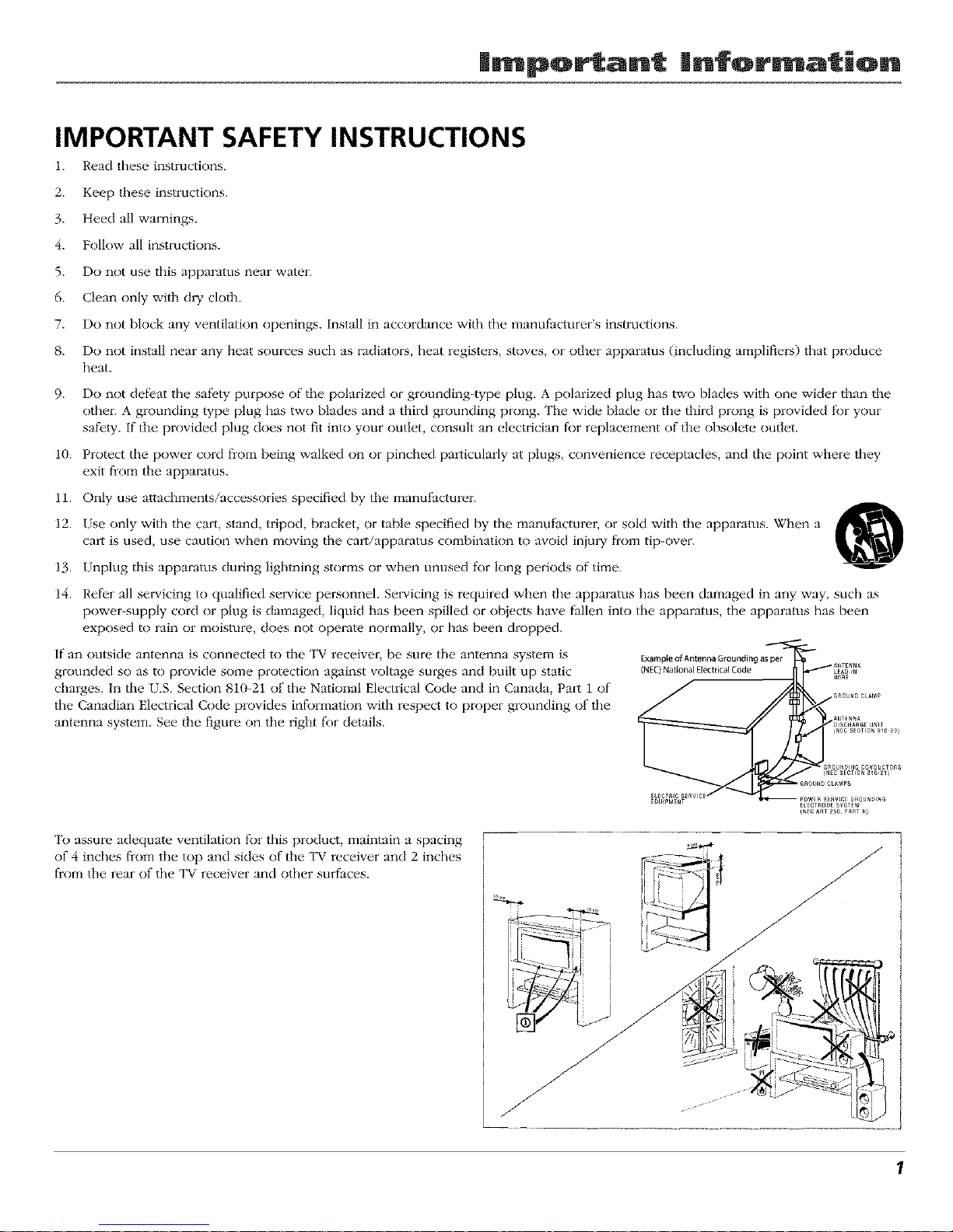
if an outside antenna is connected to the TV receiver, be sure the antenna system is
grounded so as to provide some protection against voltage surges and built up static
charges. In the U.S. Section 810-21 of the National Electrical Code and in Canada, Part 1 of
the Canadian Electrical Code provides informalion with respect to proper grounding of the
antenna system. See the figure on the right f_)r details.
E_mpleofAntennaGroundlngasper
, A_TENNA
(NEC)Nat*onal £[ectn_] Code / LEAD_N
/ //I ...........
OISCNA_GEUNIT
(NEC S_CTION _lO _0)
_ . _ROUN_INGCOND_eTOnS
GnOUNDCLAMP_
(_C_ST25aP_STN)
'[b assure adequate ventilation for this product, maintain a spacing
of 4 inches fi-om the top and sides of tile TV receiver and 2 inches
flom the rear of the TV receix'' _er and other surfaces.
J
1
Page 4
Introduction
Key Features Overview
Your "IV is equipped wifl_ features that will add to your TV viewing experience. "II_e following information summarizes a
few of these features. Chapter 3 provides more information about the rest of the TV's features and how to use them.
Hi-Pix Picture Enhancement System
"II_e Hi-Pix Picture Enhancement System incorporates two of RCA's most advanced technologies: "lYuScan Digital Reality and
the AVRPicture Projection Syste_:r_.The result is the ultimate in true-to-life picture performance that provides the optimum
picture resolution from each digital source connected to your TV (teiTestrial, DVD, satellite, and/or cable).
TruScan Digital Reality
Picture performance starts with signal processing. TruScan Digital Reality intelligent signal processing recognizes incoming
video signals and progressively converts lhem to achieve optimum digital picture performance. It enhances the picture
quality and makes you l)el as if you're close to the real thing. It also recognizes when original fihn sources have been
modified and automatically converts the analog frame rate back to its original format to bring out the detail - a process
commonly relk.rred to as reverse 3:2 pulldown.
AVR Picture Projection System
The Accurale Visual Reality high definition picture projection sys_m o_rs a brighter picture then conventional CRTs
(cathode ray tubes). These tubes creates brilliant, lifelike fideli W. The AVR 4 lens system is designed to complement the
CRTs providing accurate colors and razor sharp focus everywhere on the screen.
DVI-HDTV Input
Lets you connect a component with a DVI (Digital Visual Interface) output. DVI provides an uncompressed, digital video
interlace developed for high-bandwidth digital connection. It supports the overlay of high-resolution graphics needed by
some electronic program guide navigation and other interactive services. DVI, when combined with HDCP (High bandwidth
Digital Content Protection) technology, creates a protected digital connection. The DVI-HDTV connection is designed to
display eilher progressive scan (480p) or HD'lW (1080i) signals at a bandwidlh of up to 1.78 Gigabits per second.
PIP (Picture-In-Picture) and POP (Picture-Outside-Picture)
Description: PIP lets you watch two channels at one time - one channel on the main screen and the other in a smaller
} }
window, t O1 also lets you watch two channels at one time - one channel on the left side of the screen (the main picture)
and the other on the right.
Requirements: Press the PIP button to bring up the PIP window. Press again to bring up POP. Chapter 3 has detailed
instructions on how to use the t I1 and PO1 features.
Note: PIP and POP are not available for DVI or component video sources (CMPI or CMP2).
V-Chip: Parental Controls (for the U.S. and Canada)
Description: You can block programs and movies by content, age-based ratings, and/or movie ratings.
Requirements:
• Set up fl_e t arerztal Control menu in rite TV's main menu (Chapter 3 has details).
• The broadcasters must use the rating system when they send the program to your "IV in order for your TV to block the
program.
• Parenual controls must be locked for these settings to take affect.
2
Page 5
Tab|e of Contents
Important Safety Instructions .......................................... 1
Introduction
Key Features Overview .................................................... 2
Chapter 1: Setup & Connections
Things to Consider Before You Connect ......................... 4
Choose Your Connection .................................................. 5
Cables Needed to Connect Components
to Your TV ............................................................... 5
TV + HDTV Tuner + VCR + DVD Player ............................. 7
TV + Satellite Receiver + VCR ........................................... 9
TV + DVD + VCR .............................................................. 11
TV+ A/V Receiver or Speakers ........................................ 12
Explanation of Jacks....................................................... 13
The Front of Your TV ....................................................... 14
Front Input Jacks....................................................... 14
Front Panel Buttons .................................................. 15
Plug in the TV .................................................................. 15
Put batteries in the remote ............................................ 15
How to Use the Remote Control to Complete
the Initial Setup ............................................................ 15
Complete Auto Channel Search ............................... 16
Turn on the TV................................................................. 16
Complete the Initial Setup ............................................. 16
Set the Menu Language .......................................... 16
Changing Lists and Labels ........................................ 17
Auto Convergence (for models D40W20, D40W20B,
D52W20, D52W20B, D56W20, D56W20B, D61W20
and D61W20B only) ............................................... 17
Chapter 2: Using the Remote Control
The Buttons on the Remote Control .............................. 18
Programming the Remote .............................................. 20
Find Out If You Need to Program the Remote ...... 20
How to Use the Remote After You've
Programmed It ...................................................... 21
Using the INPUT Button .................................................. 21
Volume Punchthrough .................................................... 22
Remote Control Codes .................................................... 22
Channel 3: Special Features
Channel Banner ............................................................... 24
Autotuning ...................................................................... 24
Why You Should Use the Autotuning Feature ....... 24
How to Set Up the Autotuning Feature .................. 25
Parental Controls and V-Chip ......................................... 26
How V-Chip Works for USA and Canada ................. 26
Canada V-Chip Ratings ............................................. 29
Blocking Canadian V-Chip Ratings .......................... 30
Lock/Unlock Parental Controls ............................... 31
V-Chip Movie Rating Limit ....................................... 31
Blocking Unrated/Exempt Programs .................... 31
PIP(Picture-in-Picture) and
POP (Picture-outside-Picture) Operation .................... 32
PIPand POP Buttons ................................................. 32
Chapter 4: Using the Menu System
Sound Menu .................................................................... 33
Picture Menu ................................................................... 34
Channel Guide Menu ...................................................... 36
Time Menu ....................................................................... 36
Parental Control Menu ................................................... 36
PIP Menu .......................................................................... 37
Setup Menu ..................................................................... 37
Chapter 5: Additional Information
Troubleshooting .............................................................. 39
FCCInformation .............................................................. 41
Care and Cleaning ........................................................... 41
RCA HDTV Monitor Limited Warranty ........................... 42
Accessory Information .................................................... 44
3
Page 6
Connections Setup
Things to Consider Before You Connect
Protect Against Power Surges
• Connect all components before you plug any of their power cords into the wall outlet,
• Turn off the "IV and/or component before you connect or disconnect any cables.
• Make sure all antennas and cables are properly grounded. Refer to the Important Safety
Instructions on page 1.
Protect Components from Overheating
• Don't block w.'ntilation holes on any of the components. An'ange the components so that air
can circulate freely.
• Don't stack components.
• If you place components in a stand, make sure you allow adequate ventilation.
• If you connect an audio receiver or amplifier, place it on the top shelf so the heated air from it
won't flow around other components.
Position Cables Properly to Avoid Audio Interference
• Insert each cable firmly into the designated jack.
• If you place components above the TV, route all cables down the side of the back of the TV
instead of slraight down the middle of the TV.
• If your antenna uses 300-ohm twin lead cables, do not coil the cables. Also, keep lhe twin
lead cables away from attdio/video cables.
Important Stand and Base Safety Information
Choose the location t_r your "IV carefully. Place the "IV on a stand or base that is of adequate size
and strength to prevent the "IV from being accidentally tipped over, pushed off, or pulled off. This
could cause personal iniury and/or damage the "IV. Reli:r to the hnportant Safety lnslructions on
page 1.
Use Indirect Light
Don't place the "IV where sunlight or room lighting will be directed toward the screen. Use soft or
indirect lighting.
4 Graphics contained within thispublication arafiar reprex(_ntation only. Chapter I
Page 7
Connections Setup
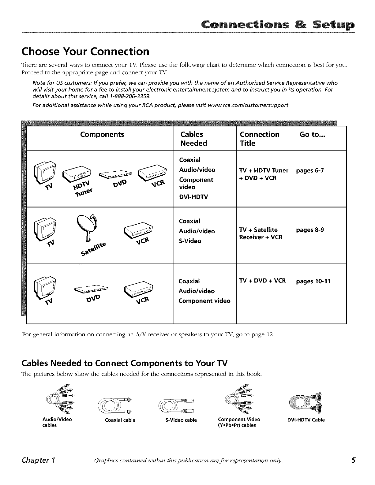
Choose Your Connection
"II_ere are several ways to connect your "lW.Please use the following chart to determine which connection is best for you.
Proceed to the appropriate page and connect your "lW.
Note for US customers: If you prefer, we can provide you with the name of an Authorized Service Representative who
will visit your home for a fee to install your electronic entertainment system and to instruct you in its operation. For
details about this service, call 1-88&206-3359.
For additional assistance while using your RCA product, please visit www.rca.com/customersupport.
Components
Cables
Needed
Coaxial
Audio/video
Component
video
DVI-HDTV
Coaxial
Audio/video
S-Video
Coaxial
Audio/video
Component video
Connection
Title
TV + HDTV Tuner
+ DVD + VCR
TV + Satellite
Receiver + VCR
TV + DVD + VCR
Go to...
pages 6-7
pages 8-9
pages 10-11
For general information on connecting an A/V receiver or speakers to your "1_, go to page 12.
Cables Needed to Connect Components to Your TV
"II_e pictures below show the cables needed for the connections represented in this book.
Audio/Video Coaxial cable S-Video cable Component Video
cables (Y,Pb,Pr) cables
DVI.HDTV Cable
Chapter 1 Graphics contained within this publication ara fiar rapre.;entation only.
Page 8
¢onn_ctiQns _ Setup
9_9
®
SATELLITERECDVER
VCR
AUDIO OUT
LR Y
DVDPLAYER
i)B pR
6 Graphics contained within thispublication arafiar repre.;entation only. Chapter 1
Page 9
Connections Setup
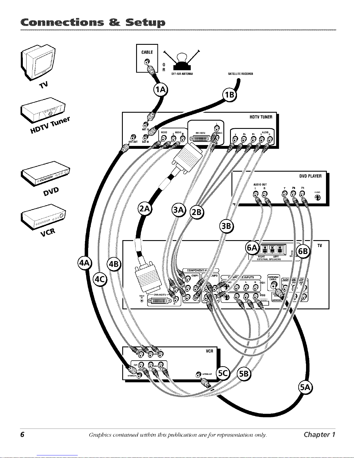
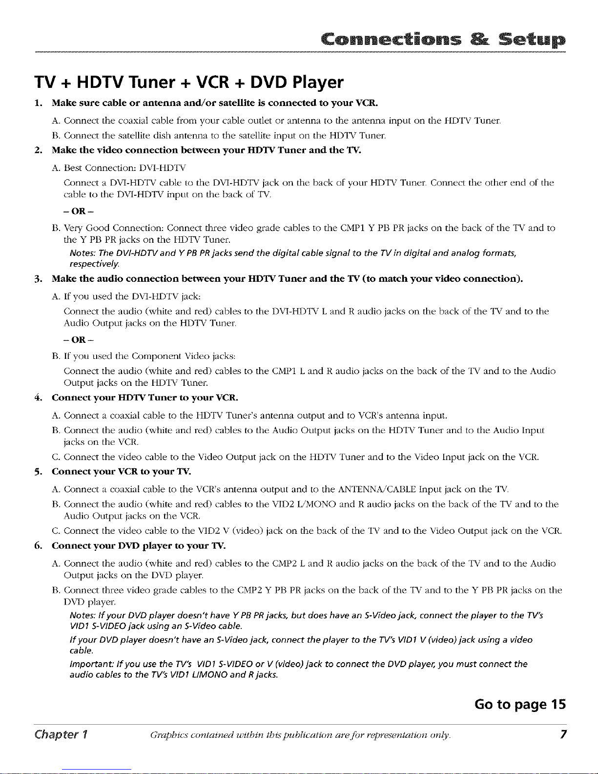
TV + HDTV Tuner + VCR + DVD Player
1. Make sure cable or antenna and/or satellite is connected to your VCR.
A. Connect tile coaxial cable from your cable outlet or antenna to tile antenna input on tim HDTV Tuner
B. Connect the satellite dish antenna to the satellite input on the HDTV Tuner.
2. Make the video connection between your HDTV Tuner and the TV.
A. Best Connection: DVI-HDTV
Connect a DVI-HDTV cable to the DVI-HDTV iack on the back of your HDTV Tuner. Connect the other end of the
cable to the DV1-HDTV input on the back of TV.
- OR -
B. Very Good Connection: Connect three video grade cables to the CMP1 Y PB PR jacks on the back of the TV and to
|he Y PB PR jacks on the HDTV Tuner.
Notes: The DVI-HDTV and Y PB PRjacks send the digital cable signal to the TV in digital and analog formats,
respectively.
3. Make the audio connection between your HDTV Tuner and the TV (to match your video connection).
A. If you used the DVI-HDTV jack:
Connect the audio (white and red) cables to the DVI-HD'IV L and R audio jacks on the back of lhe "IV and to the
Audio Output jacks on lhe HDTV Tuner.
- OR -
B. If you used the Component Video jacks:
Connect the audio (white and red) cables to the CMP1 L and R audio jacks on the back of the "IV and to the Audio
Output jacks on the HDTV Tunei:
4. Connect your HDTV Tuner to your VCR.
A. Connect a coaxial cable to the HDTV Tuner's antenna output and to VCR's antenna input.
B. Connect the audio (white and red) cables to the Audio Output jacks on the HDTV Tuner and to the Audio Input
jacks on the VCR.
C. Connect the video cable to the Video Output jack on the HDTV Tuner and to the Video Input iack on the VCR.
5. Connect your VCR to your TV.
A. Connect a coaxial cable to the VCR's antenna output and to the ANTENNA/CABLE Input iack on the TV.
B. Connect the audio (whim and red) cables to the VID2 L/MONO and R audio jacks on the back of the TV and to the
Audio Output iacks on lhe VCR.
C. Connect the video cable to the VID2 V (video) jack on lhe back of the "IV and to lhe Video Output jack on lhe VCR.
6. Connect your DVD player to your TV.
A. Connect the audio (white and red) cables to the CMP2 L and R audio iacks on the back of the "IV and to the Audio
Output jacks on the DVD player.
B. Connect three video grade cables to the CMP2 Y PB PR iacks on lhe back of the "IV and to the Y PB PR jacks on the
DVD player.
Notes: If your DVD player doesn't have Y PBPRjacks, but does have an S-Video jack, connect the player to the rV's
VID1 S-VIDEO jack using an S-Video cable.
If your DVD player doesn't have an S-Video jack, connect the player to the TV's VID1 V (video)jack using a video
cable.
Important: If you use the TV's VID1 S-VIDEO or V (video)jack to connect the DVD player, you must connect the
audio cables to the TV's VID1 L/MONO and Rjacks.
Go to page 15
Chapter 1 Graphics contained within this puhlication ara fiar rapre.;entation only. 7
Page 10

¢onn_ctiQns _ Setup
SATELLITE
RECEIVER
TV
8 Graphics contained within thispublication arafiar repre._entation only. Chapter *
Page 11
Connections Setup
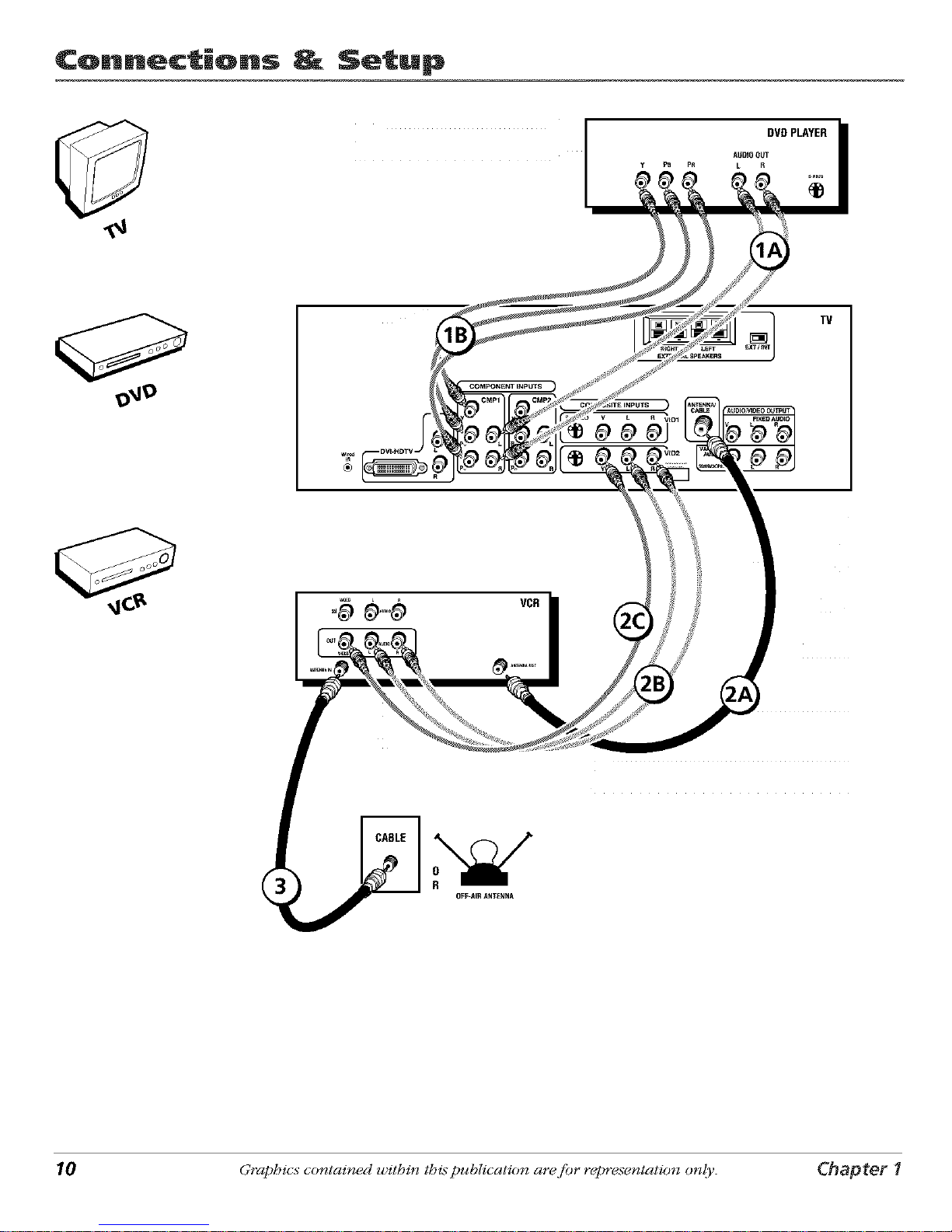
TV + Satellite Receiver + VCR
1. Connect your VCR to your TV.
A. Connect a coaxial cable to the VCR's antenna output and to the ANTENNA/CABLE Input
jack on lhe "IV.
B. Connect the audio (whim and red) cables to the VID2 L/MONO and R Audio iacks on the
back of the "IV and to the Audio Output iacks on lhe VCR.
C. Connect the video cable to the VID2 V (Video) iack on the back of lhe "IV and to the Video
Output jack on the VCR.
2. Make sure cable or antenna is connected to your VCR.
Connect the coaxial cable froi:q your cable outlet or antenna to the antenna input on the VCR.
3. Connect your Satellite Receiver to your TV.
A. Connect the audio (whim and red) cables to the VID1 L/MONO and R Audio jacks on the
back of the "IV and to the Audio Output iacks on lhe Satellite Receiver.
B. Connect the video cable to the VID1 V (Video) jack on the back of the "IV and to lhe Video
Output jack on the Satellite. Receiver.
C. If your Satellite. Receiver has an S-Video jack, connect an S-Video cable (instead of d_e
video cable in step B) to lhe S-VIDEO iack on the TV and to the S-VIDEO iack on lhe
satellite receiver.
Go to page 15
Chapter 1 Graphics contained within this publication ar_cfiar repre.;entation only. 9
Page 12
¢onn_ctiQns _ Setup
DVDPLAYER
AIJD_OOUT
y PB PR L R
TV
10 Graphics contained within this publication ara fiar repre.;entation only. Chapter 1
Page 13
Connections Setup
TV + DVD + VCR
1. Connect your DYE) Player to your TV.
A. Connect the audio (white and red) cables to the CMP1 L and R Audio jacks on the back of
lhe "lW and to the Audio OLttput jacks on the DVD player.
B. Connect three video grade cables to the CMP1 Y PB PR jacks on lhe back of the TV and to
lhe Y PB PR jacks on the DVD player.
Notes:
If your DVDplayer does not have YPBPRjacks, but does have an S-Videojack, connect the
player to the VID1S-VIDEOjack on the TVusing an S-Videocable.
If your DVD player does not have an S-Videojack, connect the player to the VID1 V(Video)
jack on the back of the TVusing a video cable.
Important: If you usethe VIDI S-VIDEOor V (Video)jack to connect your TV to the DVD
player, you must connect the audio cables to the VIDI L/MONO and Rjacks on the T_
2. Connect your VCR to your TV.
A. Connect a coaxial cable to the VCR's antenna output and to the ANTENNA/CABLE Input
jack on the "1_.
B. Connect the audio (white and red) cables to the VID2 L/MONO and R Audio iacks on the
back of the TV and to the Audio Output iacks on the VCR.
C. Connect the video cable to the VID2 V (Video) iack on the back of the "1_ and to the Video
Output jack on the VCR.
3. Make sure cable or antenna is connected to your VCR.
Connect the coaxial cable frol;q your cable outlet or antenna to the antenna input on the VCR.
Go to page 15
Chapter 1 Graphics contained within this publication ara fiar rapre.¢entation only. 11
Page 14

Connections Setup
TV+ A/V Receiver or Speakers
"II_ese are two different ways your TV uses a component to hear audio.
1. Connect audio cables to either lhe FIXED or VARIABLE AUDIO L and R OUTPUT jacks and
to the Audio lnpul_s on the A/V receiver.
• FIXED provides fixed-level audio output from the "IV. This audio output is ideal for
connecting to an A/V receiver that has its own w)lume control.
• VARIABLE provides variable-level audio output. Volume levels can be con_olled by
lhe volume controls on the "IV and "IV remote con_ol.
-Oli-
2. Use speaker wire to connect the "IV to external speakers.
• The EXT/1NT switch beside the iacks let you turn the "lV's internal speakers on or
off. If you connect external speakei:s, slide the swilch to EXT so the audio is sent to
lhe external speakers only. Choosing 1NT sends the audio to the "lV's speakers only.
Note: The external speaker rating is8 ohms with 15 watts power handling capabilities.
f
m_ _ _ REmWR
I I
,,__
..... _
;;;;; rA_vl_oou_
\
Connect to either FIXED
or
VARIABLE Output
12 Graphics contained within this publication ara fiar rapre.;entation only. Chapter 1
Page 15
Connections Setup
Explanation of Jacks (in alphabetical order)
"II_issection desclibes the jacks you can use to make connections. There are several ways to
connect components to your "IW.
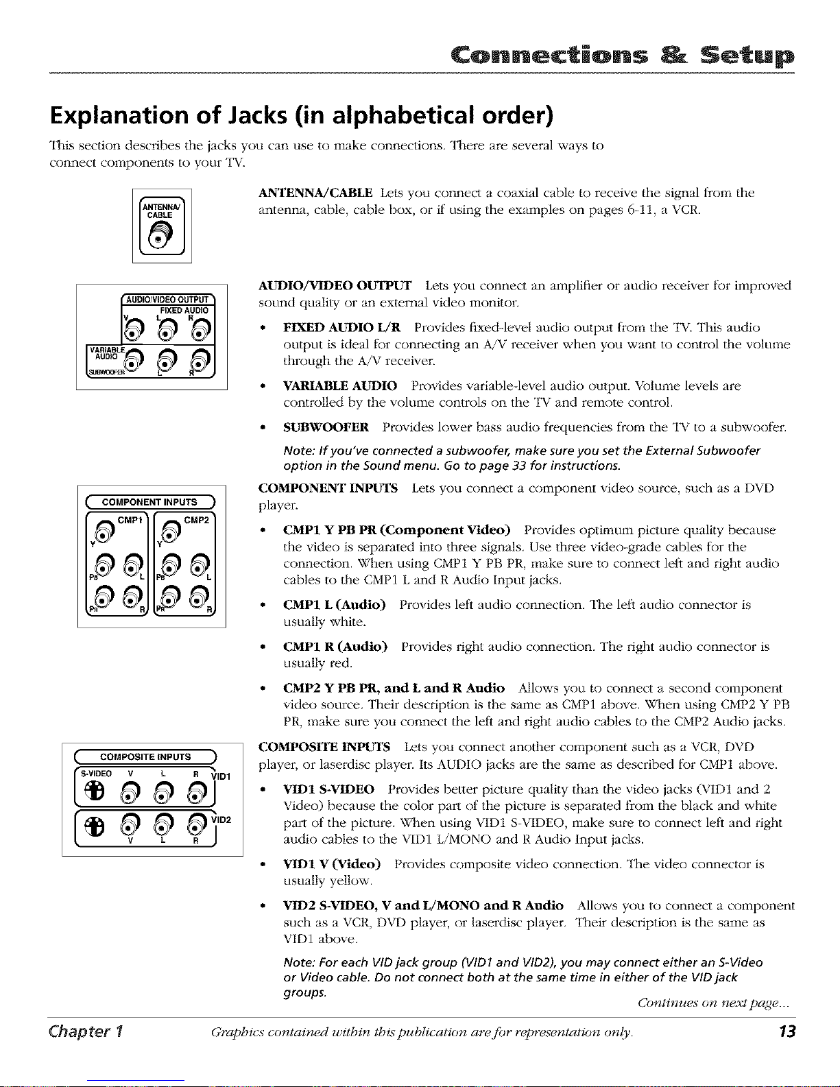
ANTENNA/CABLE Lets you connect a coaxial cable to receive the signal from the
antenna, cable, cable box, or if using the examples on pages 6-11, a VCR.
AUDIO/VIDEOOUTPUT
FIXED AUDIO
VARIABLE
AUDIO
p pj
AUDIO/VIDEO oUTPUT Lets you connect an amplifier or audit) receiver for improved
sound quality or an external video monitor.
• FIXED AUDIO L/R Provides fixed-level audio output from the TV. This audio
output is ideal t_r connecting an A/V receiver when you want to control the volume
through the A/V receiver.
• VARIABLE AUDIO Provides variable-level audio output. Volmne levels are
controlled by the volume controls on the TV and remote control.
COMPONENTINPUTS
j.,_CMP1 I=_CMP2
IInl_
IlalW I(ml7
, ?
• SUBXVOOFER Provides lower bass audio frequencies from the "IV to a subwoofer.
Note: If you've connected a subwoofer, make sure you set the External Subwoofer
option in the Sound menu. Go to page 33 for instructions.
COMPONENT INPUTS Lets you connect a component vMeo source, such as a DVD
player.
CMP1 Y PB PR (Component Video) Provides optimum picture quality because
the video is separated into three signals. Use three video-grade cables for the
connection. When using CMP1 Y PB PR, make sure to connect left and right audio
cables to lhe CMP1 L and R Audio Input iacks.
• CMP1 L (Audio) Provides left audio connection. The left audio connector is
usually white.
• CMP1 R (Audio) Provides right audit) connection. The right audit) connector is
usually red.
• CMP2 Y PB PR, and L and R Audio Allows you to connect a second component
video source. Their description is the same as CMP1 above. When using CMP2 Y PB
PR, make sure you connect the left and right audit) cables to the CMP2 Audio iacks.
( COMPOSITE INPUTS
0;io2
COMPOSITE INPUTS Lets you connect another component such as a VCR, DVD
player, or laserdisc player. Its AUDIO iacks are the same as described for CMP1 above.
VID1 S-VIDEO Provides better picture quality than the video jacks (VID1 and 2
Video) because the color part of the picture is separated from the black and while
part of the picture. When using VID1 S-VIDEO, make sure to connect left and right
audio cables to the VID1 L/MONO and R Audio Input jacks.
• VID1 V (Video) t rovides composite video connection. The video connector is
usually yellow.
• VID2 S-VIDEO, V and L/MONO and R Audio Allows you to connect a component
such as a VCR, DVD player, or laserdisc player. Their description is the same as
VID1 above.
Note: For each VID jack group (VIDI and VID2), you may connect either an S-Video
or Video cable. Do not connect both at the same time in either of the VID jack
groups. Continues on n_xt page..._
Chapter 1 Graphics contained within this publication ara fiar rapre,;entation only. 13
Page 16

¢onn ctiQns Setup
RIGHT LEFT
EXTERNAL SPEAKERS
DVLHDTV Input Lets you connect an HDTV Tuner with a DVI output.
DVI (DigitaJ Visual Interface) Provides an uncompressed, digital video interface
developed for high-bandwidth digital connection. It supports the overlay of high-
resolution graphics needed by some electronic program guide navigation and other
interactive services. DVI, when combined with HDCP (High bandwidth Digital
Content Protection) technology, creates a protected digital connection. The DVI-
HDTV connection is designed to display either progressive scan (480p) or HDTV
(1080i) signals at a bandwidth of up to 1.78 Gigabits per second.
• L (Audio) Provides left audio connection when using the DVI jack. "II_e left audio
connector is usually white..
• R (Audio) Provides right audio connection when using the DVI iack. The right
audio connector is usually red.
Note: Remember to connect the left and right audio cables because the DVI cable
carries only the picture signal, not the sound.
EXTERNAL SPEAKERS
• Right and Left Speaker Terminals Let you connect external left and right
speakei:s to the "IV to receive left and right sound.
• EXT/INT (switch) Lets you turn the TV's internal speakers on or off. EXT sends
audio to external speakers only. INT sends audio to the TV's internal speakers only.
Wired IR This jack is for connecting a wired remole control system, which is primarily
for professional installers. If you're using the remote that was included with your "IV,
don't plug anything into this iack.
The Front of Your TV
Front Input Jacks
"II_e"IV has front inputs t_r convenience: one set of audio/video input jacks, an S-Video jack and a headphones iack. The
iacks are ideal for using a video game console or a camcorder. Locate the jacks either on the l¥ont of the TV or on one of
the sides. To access the component you connected to the front of the "IV, press the INPUT button on your remote until
FRNTappears on the screen.
Note: When connecting a component that usesa monaural cable, suchassome camcorders, use the Left (mono) input
jack to get sound from both speakers.
PHONES Allows you to connect headphones to listen to the sound coming l¥om the "IV. To adjust w_lume control of
the headphones, press the VOL > or VOL < button (the volume display appeai:s). Press the arrow up or down button (the
headphone volume display appears), lhen press the right or left arrow button to adjust the headphone w_lume.
VIDEO (in) Receives video from another component such as a camcorder, video game console or VCR.
E/MONO and R AUDIO Receives audio from anolher component such as a camcordeL video game console or VCR.
S-VIDEO (in) Allows you to connect an S-Video cable from another component. Make sure you also connect audio cables
from the component to the "IV.
Note: Do not connect an S-Video and a regular video cable to the FRNrjacks at the same time.
14 Graphics contained within this publication ara fiar repre.;entation only. Chapter 1
Page 17

Connections _ Setup
Front Panel Buttons
If you cannot locate your remote, you can use the front panel bu|tons of your TV to operate many of |he "l_v_'s features.
MEI_U/OK Brings up the Main menu. In the menu system, it selects highlighted items.
Eli v Scans down through lhe cun'ent channel list. In lhe memt system, acts like down arrow button on tile remote control
and adiusts menu controls.
eli A Scans up through the channel list. In lhe menu system, acts like up arrow button on the remote control and adiusts
menu controls.
¥OL < Decreases the volume. In lhe menu system, acts like let) arrow button on the remote con_ol and adjusts menu
controls.
¥OL > Increases the volume. In lhe menu system, acts like right arrow button on lhe remote control and adiusts menu
controls.
POWER Turns the TV on and oil
Plug in the TV
Plug the end of lhe power cord into a grounded wall oullet. Insert the plug
completely into the outlet.
Put batteries in the remote
• Remove the battery compartment cover from the back of the remote by
pushing the tab and lifting off the cover.
• Insert 2 "AA" fresh batteries. Make sure the polarities (+ and -) are aligned
correctly.
• Replace the cover.
TVbu_on
button
Arrows
How to Use the Remote Control to
Complete the Initial Setup
The technical term is "Navigation" - how you move through the on-screen menus.
The lheory is the same throughout lhe menu screens: highlight your choice and
select it.
To highlight a menu item, press the arrow buttons on the remote to highlight one
of the items listed on the screen. Use the up or down arrow button to move up or
down. Use the right or let) arrow button to move right or left.
To select the item that you've highlighted, press OK.
Note: Highlighted means that the menu item stands out from other menu
items on the list (appears darker, brighter, or a different color).
Chapter 1 Graphics contained within this publication are fiar repre.;entation only. 1_
Page 18

Connections Setup
Turn on the TV
Press "IV on the remote, or press POWER on lhe "lW's front panel.
Note: Pressing the TV button not only turns on the TV, but puts the
remote into TV mode. "TV mode" means that the buttons on the remote
control operate the TV's functions.
Tip
To access the setup menus manually, press
MENU and choose SETUP
Complete the Initial Setup
"II_e menu system in your "lW allows lhe "lW's features to work properly. The
first time you turn on your TV, the setup screens appear.
Set the Menu Language
"II_e first part of the setup allows you to select your preferred language for the
menu system.
If English is your preferred language, press OK. If you want to choose another
language, press lhe down arrow button until that language is highlighted, and
press OK.
Complete Auto Channel Search
The next screen asks you to make sure you've connected the TV to a cable,
satellite, or oil'-air signal. When you're sure that a signal is connected to your
"1_, press OK on your remote to go to the Channel setup screen.
In the Channel setup screen, you can launch the Auto channel search by
pressing OK. The Auto channel search allows lhe TV to search for all channels
viewable lhrough your anlenna or cable "lWsystem. This is sometimes called
autoprogramming. When the channel search is complete, press OK to access
the List & Labels screen.
16 Graphics contained within this publication ara fi)r rapre.;entation only. Chapter 1
Page 19

Connections Setup
Changing Lists and Labels
"II_eList & Labels part of _e setup lets you edit your channel list and choose or
create a personal six-character label for each channel.
Note: Changing List and Labelscan be time consuming. You can change
these at a later time by accessingthe Setup menu.
1. Press the left or right arrow to scroll fllrough tlle channels and choose the
one you want to edit.
2. Press the down arrow {o highlight the In channel list option. Press the let)
or right arrow button to add (the box is checked) or remove (tim box is
unchecked) the channel from llle list.
.
Press the down arrow to highlight the Channel label option. Press the left
or right arrow button to scroll through the available list of 25 most common
labels. The last option in the list allows you to create your own sLx-
character label for the channel (the first letter of the label is highlighted).
4. Press the 1 or 2 nmnber button to change the first letter of llle label.
.
6.
Press the fight arrow to highlight the second lette_; then press the 1 or 2
nmnber button to change the second lettei; etc...
When you are finished creating your label, press OK. For models D34W20
and D34W20B, press CLEAR to tune to the last selecled/available channel
in your channel list. For models D40W20, D40W20B, D52W20, D52W20B,
D56W20, D56W20B, D61W20 and D61W20B, select Go back to go to the
Auto Convergence menu.
Note:
If you're using an HD source (such as an
HDTV tuner or HDTV satellite receiver) on the
CMPNT or DVI input, you should run Auto
convergence separately for that input as well.
Tune to the input you're using for the HD
source, then go to page 38 for information
on Auto convergence.
Auto Convergence
(for models D40W20, D40W20B, D52W20, D52W20B,
D56W20, D56W20B, D61W20 and D61W20B only)
Your TV's picture tubes might have been disturbed during delivery or alter you
moved the "IV, causing the color in your "1_ to be out of alignment. The colors
adjust by starting auto convergence.
IMPORTANE" Auto convergence works best once the TV has warmed up
for at least an hou_ If you've just unpacked your TV, it's a good idea to
repeat the Auto convergence function when the TV's been running for at
least an hour See page 38 for more information about Auto convergence.
1. Press OK to begin auto convergence.
2.
When the auto convergence is complete, the Red center convergence menu
appem:s. The cross in the middle of the screen should be yellow. If it is not,
use the arrow buttons to move the red cross to overlap tl_e green cross.
Press OK when adjusunents are complete.
.
"I]_e Blue center convergence menu appears will1 a cyan cross in the middle
of {he screen. If it is not, use the arrow buttons to move Ihe blue cross
to overlap the green cross. Press OK (tim TV tunes to the last selected/
available channel in llle channel list).
Chapter _ Graphics contained within this publication are fiar representation only. 17
Page 20

Using the Remote Control
Indicator
iiiiiiiiiiiii!!;iiiilliiiiiiiiiii i;i i!i iiiiiii i !i!i¸iiiiiii!i iiiii
!!!!!iiiiiiiiiii i i i ! i!!!! iii j i.......................
OC_ PIP ;G
liiiiiiiiiiili!!i
RECORD STOP PAUSE
iiiii
The Buttons on the Remote Control
(0-9) Number Buttons Enter channel numbers and time settings directly
through the remote control.
"I5 enter a one-digit channel, enter a zero first. To enter a _wo-digil channel, press
the two digits. To enter a lhree-digit channel, press and hold the "1" button until
"1" and lwo dashes (- -) appear, then add the second two digils. Example: to tune
to channel 123, press and hold 1 until "1- -" appears, release the 1 button and
then press 2 and 3.
ANTENNA In VCR mode (if programmed), lhis button works as a TV/VCR button
tbr some VCRs. In SAT mode (if programmed), this button works as a "I_/SAT
button for some satellite receivers.
Arrows Used to highlight different ilems in the "IV menu and to adjust the menu
controls. The up and down ai_'ows move _he PlP window when no menus are on
the screen. When walching TV without the PIP window or menu system in use,
the let'_ and right arrows (ZOOM - and ZOOM +) change the current tk)rmat of the
screen (4:3, Zoom 14:9, Zoom 16:9, Zoom 16:9 A/V, Cinemma, regular mode 16:9).
AUDIO Places _he remote in audio mode to operate a component (such as a CD
player, audio receiver, amplifier/receiver) that you've programmed to work with
this button.
AUX/HD Puls the remote in AUX/HD mode. As a default, this button controls
some models of RCA HD'IN Tuners. It can also be programmed to operate some
brands of an additional remote-controllable component, including some other
brands of HDTV tuners. The Autotuning feature for this button works only with
HD'IN tuners (see page 24 for more intk)rmation on Aulotuning).
CH + or CH - Scans up or down through lhe cmTent channel list. Press once to
change the channel up or down; press and hold to continue changing channels.
For some GE, RCA or Proscan DVD players, the CH bultons work as chapter skip
buttons.
CLEAR Removes any menu or display from the screen and returns you to normal
viewing. Also exits PIP or POP if no menu is displayed.
DISC MENU No function available in "IV mode. For some RCA, GE or Proscan
DVD playe_:s, this bulton [)rings up the Disc menu.
DVD Puts lhe remote in DV1-) mode and, if Autotuning is enabled, will turn on
the "IV and tune to the chosen input channel.
FREEZE When watching TV, l?'eezes the picture until you press any bulton on
the remote to resume normal TV viewing. "II_e FREEZE feature automatically times
out after a short time. Please note that when you "unt)'eeze" you go back to live
programming (skipping any programming that occurred during the freeze).
Note: The FREEZEfeature does not work on signals from the DVI-HDTV, CMP1or
CMP2inputs in progressive scan(480p) or HDTV (1080i) modes.
Do not use the Freeze feature for an extended period of time. This can cause
the image to be permanently imprinted on the picture tube. Such damage is not
covered by your warranty. Pressany button to unfreeze the picture at any time.
GO BACK Returns you to lhe previous channel.
GUIDE Brings up the Channel Guide menu.
Indicator Indicates the programming mode when programming lhe remote to
control components. The indicator flickers when the remote batteries are low and
you press a button.
18 Gtz_phics contained_ u_ithin tbis publication are fi)r representation_ onlj. Chapter 2
Page 21

Using the Romote Control
Tip
The component button corresponding to
the mode you're in flickers when the remote
batteries are low and you press a button on
the remote.
A warning message may also appear on the
screen when you press a remote button and
the batteries are low.
To turn off most the RCA, GE, and Proscan
components that are connected to the TV,
press ON.OFF twice within two seconds.
This feature only works with most RCA, GE,
and Proscan products.
Note:
The DVD, VCR, SATICAB, AUX/HD, and AUDlO
buttons also turn on most RCA, GE, and
Proscan products.
INFO Brings up the channel banner; press again to clear the screen.
Accesses the available video input channels (VID1, VID2, FRNT, CMP1,
CMP2 and DVI). Press the CH+ or CH- bulton to resume "IV viewing.
LIGHT Press to illuminate some of the remote con_ol's buttons. To conserve
battei T powei, the light turns off"alier several seconds. Backlight won't activate if
hatteries are low, but blinks on and off quickly.
MENU Brings up the Main inenu.
MUTE Reduces the "lV's w)lume to ils minilnum level. Press again to restore
the volume.
OK When in the menu system, selects highlighted items. When watching
"IV,freezes the picture until you press any button on the re,note to resmne
normal TV viewing. Please hOle thai when you "unfreeze" you go back to live
programming (skipping any programming that occurred during the freeze).
ON.OFF When in "IV triode, turns the "IV on and off. If in another component
mode (VCR, DVD, SAT/CAB, etc.) and programmed, will turn the component on
and off. When pressed twice wilhin two seconds, the ON*OFF button turns off
_nost RCA, GE and Proscan components.
PIP Press once to bring up the small picture-in-picture (PIP) window. Press
again to bring up the picture-outside-picture (POP) windows. Press to remove
POP. (See Chapter 3 for more intk)rmation about using PIP.)
PIP + or PIP - When using PIP or POP, changes the channel in the PIP
window.
PRESETS Displays dm Picture and Sound preset selIings. Use the up and down
arrow bultons to highlight either Picture or Sound settings. Use the let't and right
arrow bulIons to change to a different Picture or Sound preset.
REVERSE, PLAY, FORWARD, RECORD, STOP, PAUSE If programmed,
provide transport con_ol for some remote-controllable VCRs, DVD players, tape
decks, and CD players.
SAT/CAB Puts the remote in SAT/CAB mode and, if Autotuning is enabled, will
turn on the "IV and tune to the correct input channel.
SKIP Press once belk)re changing channels and the "IV will wait 30 seconds
belBre returning you to the original channel. Press repeatedly to add more time.
SLEEP Brings up lhe Time menu wi_h the Sleep timer i_em highlighted, if
you've sel the time. If you haven't set lhe time, the Time menu ilem will be
highlighted, prompting you to enter the correct time.
SWAP When using PIP, swaps the main picture with the PIP window. When
using POP, swaps the left and right pictures.
'IV Turns on the "IV and puts the remote in "IV mode. Also displays the channel
I)annei:
VCR Puts the remole in VCR mode and, if Autotuning is enabled, will turn on
the "IV and tune to the correct input channel.
VOL- or VOL + Decreases or increases the TV's w)lume.
ZOOM In PIP mode, changes the size of the PIP window.
Chapter 2 Graphics contained_ u,ithin this publication are fi_r representation_ onlj 19
Page 22

Using the Remote Control
S
Indicator -- m o.......
You'll use these buttons when
you program the remote.
Important: The remote may not
be compatible with all models of
all brands of components. It also
may not operate all functions of
the remote that came with your
component.
To stop the automatic code search without
programming any components, press and
hold CLEAR until the indicator on the remote
turns off.
Programming the Remote to Operate
Other Components
The unive_:sal remote can be programmed to operate most brands of remote
controllable components. "II_eremote is already programmed to operate most
RCA, GE, and Proscan components.
Also, lhe AUX button can be programmed Io operate most brands of an
additional remote-controllable component (such as a VCR, DVD player, CD
playei, satellile receiver, cable box or audio receiver).
Note: The YVbutton can't be programmed on this remote.
Find Out If You Need to Program the Remote
To determine whether the universal remote needs to be programmed to operate
one of the components connected to your "IV, such as a VCR, do the following:
1. Turn on the component (in this example, a VCR).
2. Point the remote at lhe component.
3. Press lhe corresponding component button (in this example, the VCR
button).
4. Press ON*OFF to see if the VCR responds. If the VCR doesn't respond, you
need to program the remote to operate it.
Programming the Remote
There are two ways to program the remote control:
* automatic code search
* direct enlry
Using Automatic Code Search
The _llowing instruclions can be used _ program the remote to operate each
of your components. If you want to stop the automatic code search wilhout
programming any of your components, press CLEAR until the indicator on the
remote turns off.
1. Turn on lhe component you want to operate (VCR, DVD player, etc.)
2. Press and hold the component button you want Io program (VCR, DVD,
etc.). While holding lhe component button, press and hold ON*OFF until
the indicator on the remote turns on, then release both buttons.
3. Point lhe remote at lhe component. Press and release PLAY,lhen wait 5
seconds or until the indicator on lhe remote stops flashing.
At Ibis point lhe remote is searching for the correct code to program. If,
after 5 seconds, lhe component you want to operate does not turn off,
press PLAYagain to tell lhe remote to search the next set of codes.
Continue pressing PLAY unlil lhe component turns oil"or lhe indicator lighl
on lhe remote turns oft'. If lhe indicator light turns off, lhen all codes for that
particular component have been tested once. If lhe component does not turn
oil, lhen the remote can't be programmed to operate lhat component.
If the component you want to control does turn off:
1. Press and release REVERSE, then wail 2 seconds. Repeat this step until the
device turns back ON.
2. To finish, press and hold STOP until the indicator on the remote, turns off.
A code that controls your component has been saved to that remote button.
20 Graphics contained_ u_ithin this publication are fi)r representation_ onlj Chapter 2
Page 23

Using the Romote Control
Important note for direct entry
You must continue pressing the component
button while you enter the code.
Let's say you have a Zenith VCR. To program
the universal remote to operate the VCR, you
would:
Press and hold the VCRbutton while you en-
ter the first code listed for Zenith in the VCR
Codes column.
Release the VCR button. Press ON,OFF to see
if the VCR responds. If it doesn't, follow the
same steps, but enter the second code for
Zenith VCRs instead of the first.
Using Direct Entry
1. Turn on the component to be programmed.
2. Look up the brand and code number(s) for the component on the code list
in this section.
3. Press and hold the component button you want to program on the remote.
4. Enter lhe code from the remote control code list on lhe following pages. If
lhe indicator flashes, you have either entered an invalid code or the button
isn't programmable.
5. Release the component button, point the remote at the component and
lllen press ON-OFF to see if the component responds to the command. If it
doesn't, try pressing the component button and lllen ON* OFF again.
* If you get no response, repeat these steps using llle next code listed for
your brand, until llle component responds to the remote commands.
* If you fry all tile codes tbr your component brand and none work, try the
automatic code search method. If automatic code search doesn't find the
code, the remote is not compalible wilh your component.
ComponentButtons
f
ii)i)i_ii,'_!i,)!i_))i_
©
Note
Some of the remote's buttons might operate
differently for other components, especially
when you're using another component's menu
system.
How to Use the Remote After You've Programmed It
Because this universal remote can control several different components ('IV,
DVD, VCR, satellite receiver, etc.) it uses operational modes triggered by the
component buttons. For exmnple, if you want the remote to operate the TV,
you would press the "IV button to put |he remote into TV mode before you
could control the TV.
1. Press the appropriate component button (DVD, TV, VCR, SAT/CAB,
AUX/HD, AUDIO) to set the remote to conlrol the component.
2. Press ON*OFF to turn the component ON or OFF.
.
Use the remote buttons that apply to that component. "II_ecomponent
button on your remote lights up when you press valid buttons while in that
component's mode.
Notes:
The remote may not be compatible with all brands and models of
components. It also may not operate all functions of the remote that
came with your component.
If you keep pressing buttons and nothing happens, the remote is
probably in the wrong mode. You must press the component button
that matches the component you want to operate (i.e., if you want to
operate the VCR, press VCRon the remote control to put the remote
in VCR mode.)
Using the INPUT Button
)
Use the INt UT button to scroll through the available input channels and view
components you have connected to the TV.
1. Press TV to place the remote in TV mode. Make sure the component you
want to view is turned ON.
2. Press INPUT until you reach the correct input channel.
3. To return to the channel you were previously watching on TV, press CH+
or CH- button.
Chapter 2 Graphics contained_ u_ithin this publication are fi)r representation__ _ only. 21
Page 24

Using the Remote Control
Volume Punchthrough
You may find this feature helpful if you've connected your components to an attdio/video receiver (A/V receiver) or
amplifieL but you want to use the TV's remote control to operate the volume for a component that is connected to the
audio/video receiver. An example follows.
Let's say you've connected your DVD player to your audio/video receiver. You've also programmed your TV remote control
to operate your DVD player. Since the DVD player gets ils volume through the audio/video receiver, you would have to
bounce back and l_rth between two remote consols: the a/v receiver's remote to adiust the volume and the TV's remote
control to operate the DVD player.
"Ille Volume Punchthrough Feature eliminates the need 15r you to use two remote, consols and saves a button press when
you're using the "I.Vremote to adjust lhe volume. In effect, you are telling the "I.Vremote to relrieve and send volume
commands from lhe A/V receiver whenever the TV remote is operating the DVD player (in DVD mode).
Therefore, after you've successfully set up the Volume Punchthrough Feature, whenever the "IV remote is in DVD mode
(press the DVD button) and you want to adjust the w)lume, you only have to press the VOL + or VOL- buttons. Follow the
instructions below to set up Volume Punchthrough.
IMPORTANE"First, you must program the AUDIO button on the TV'sremote control to operate your audio receiver
or amplifie_ Go to page 20 for instructions. If you can't program this remote to operate your audio receiver, Volume
Punchthrough won't work.
While setting up Volume Punchthrough, it's best to point the remote away from components.
1. Decide which rnode lhe rernole will be in when |he volurne from the audio receiver "punches through." The mode will
be one of the component buttons (TV, DVD, SAT/CAB, VCR, or AUX/HD).
2. Press and hold the VOL- button. Keep pressing VOL- while you press and release lhe component button you chose in
step 1 (TV, DVD, SAT/CAB, VCR or AUX/HD).
3. Then press and release the AUDIO button since the sound will be coming from lhe audio/video receivei: Release lhe
VOL- button.
4. Now, test it by turning on your audio receiver or amplifer.
5. Turn on the component lhat is connected to lhe audio/video receiver or amplifier (a DVD playeL for example).
6. Put the TV's remote in DVD mode by pressing the DVD button, and play a disc.
7. Press VOL+ or VOL-. The volume from the audio receiver should increase or decrease accordingly.
Deleting All Punchthrough Commands
To delete all programmed Volmzqe Punchthrough settings and return the remote control back to the fa_oly defaults (TV _r
all modes except AUDIO), press and hold lhe VOL- button (LED of the Volume Punchthrough component lights). While
holding the VOL- butlon, enter the code, 000, using the number bultons. All component LEDs turn on for 2 seconds and
then turn off. The remote returns to the factory settings.
Note: If an invalid button is pressed, the LED (all component LEDsor single LED)blinks 4 times and LEDturns off. At this
point, you must start ove_
Remote Control Codes
Audio Codes
Programmable _)r the AUDIO and
AUX/HD buttons.
lUX/Dtmensia/Lyra Wlrele_s
RCA ...................... 4004
Audio Cassca te
GE ........................................... 4006
RCA ....................... 4006
CD Players
ADC ........................... 4055, 4056, "i066
Aiwa ................................. 4049, _1057
Akal ...................................... 4058
Denim ........................................ 4060
Ihllerson ................... 4040
Fisher ........................... i041, 4063, 4064
GE ...................................... 4007, 4065
Hitachi .................................. 4042
IVC .......................................... 4043
Kenwood ....................... _044, 4067, 4068
Luxman ..................................... 4069
Mamntz .................................. 4046
MCS ....................................... 4070
Mitsubishi ........................... 4071, 4072
NEC ......................................... 4045
Onkyo ................................... 4047
Panas_flc ................................... 4188
Pk)neer .................................... 4049
RCA ............................... 4007, 4050, 4062
Sears ................................... 4059
S_ly ................................. 4051, 4061
'_chnics .................................. 4052
'_hiba ....................................... 4073
Yamalla ................. 4053. 4054
Phono
Gi ............................................ 4005
RCA ..................... 4005
Receiver/Tuner/AMP
Ai_l .............. 4008:1009, 4010, t011, 4012, 402I
Denon ..................................... 4027
GE ...................................... 4003
Harman Ka_l ................................ 4020
]BL ..................................... 4020
]VC ........................................ 4013
Kenwood ................................. 4014
Onkyo .................................... 4022
Optimus ................................. 4028
Panas_lic ............................... 4023, 4024
RCA ......................... 4003, 4015, 4029, 4030
Sherwood ................................. 4026
S_ly ............................ 4016, 4017, 4025
1_chnics .................................. 4023, 4024
Yamalla ................. 4018, 4019
22 Graphics contained, u_ithin this publication are fi_r representation, on{v Chapter 2
Page 25

Using the Romoto ¢ontro|
Cable Box Codes
ProgmmmabIe fi)r SK[TCAB and AIX/ItD buttons.
ABC ..................... 5002, 5003, 500L 5006, 50i5
A_her .................................. 5008, 5009
Cablevie_ ................................. 5007
Contec ..................................... 5{)15
Eas_rn .................................... 5016
GE ...................................... 5002, 5003
Gemim ................................ 5017, 5018
GeneraI Instrul_nts ......................... 5003
Hamlin ................... 5019, 5020, 5021, 5026, 5033
Hitachi ...................................... 5003
lermld .............. 5003, 5017, 5022, 5023, 5039, 5045
Magnavox .................................. 5024
Memorex .................................. 5026
Movie Time ................................ 5025
NEC ..................................... 5005
NSC ....................................... 5025
Oak ................................... 5015, 5027
Panas_fic ............................ 5041, 5{)44
Philips 50ii, 5012, 5013, 5014, 5018, 5024, 5028, 5029, 5030
Pi(meer ................................ 5031, 5032
Proscan .............................. 5002, 5003
RCA ......................... 5007, 5040, 5042, 5044
Realistic ...................................... 5009
Samsung ................................... 5032
S<_entiflc Atlanta ................. 5006, 5034, 5035, 5036
Signature .................................. 5003
Sprucer ....................................... 5044
Standa_ Comp_ment ...................... 5037, 5038
Star<ore ................................. 5017, 5045
Stargate ................................... 5017
'RK:om .............................. 5004, 5022
United Cable ................................ 5045
Univer_lI .......................... 5008, 5009, 5010
View Star ............................. 5015, 5024, 5025
Zenith .................... 5043
DVD codes
Programmable for DVD and AUX/HD buttons.
DVD
Aiwa .................................... 3010, 3{)21
Apex ................................... 3023, 3{)24
Broksonic ............................... 302_, 3075
D I( ;'_oo .................................... 3{)28
Denim ............................. 3029, 3030, 3{)31
_hnerson .......................... 3032, 3033, 3076
Funai ..................................... 3033
GE ................................. 3000, 3034, 3035
(o Video ............................... 3077
Hitachi ................... 3009, 3067, 3068, 3069, 3070
IVC .............................. 3003, 3011, 3078
Kvnwood .................................... 3071
K_mka ................................... 3012, 3013
K_>s ....................................... 3085
Iaslmk .................................... 3{)87
Magnavox ............................... 3004, 3036
MemoJ<_x .................................. 3037
Mintek ...................................... 3038
Mitsubishi .................................. 3005
NAD ........................................ 3032
Noment ............................... 3039, 3040
Onkyo .................................... 3041
Oritron .................................... 3047
Panasonic ............................... 3014, 3{)t2
Philips ................................... 3004, 3020
Pioneer ....................... 3006, 3043, 3044, 3045
Proscan ................................ 3000, 3046
Qx_estar .................................. 30t7
RCA ..................... 3000, 3002, 3018, 3079, 3086
Samsung ................ 3072, 30_3 3074, 3080, 308I,
Sansui ..................................... 3049
Sanyo ................................ 3015, 3082
Shlq_ ............................. 3050, 3052, 3053
Sony ........... 300_, 3016, 3017, 3054, 3055, 3056, 3083
Sylvania .................................. 3033
'l_ac ......................................... 3057
'l_-chnics ................................. 3{)58
'RMfiba .................. 3008, 3018, 3059, 3060, 3061
Yamaha ............................. 3062, 3063, 3064
Zenith ................. 3019, 3065, 3081
Portable DVD
Aiwa ....................................... 3022
Audiow)x .............................. 3025, 3026
Panas_fic .................................. 3030
RCA .......................................... 3{)66
Sharp .................... 3051
DVDNCR Combo Codes
DVD and AUX.,ftD buttons can use DVD codes;
VCR and AUX/IID buttons can use VCR codes
............................................................... DVD ................ VCIR
Bn)ks/)nic ........................ 3075 ......... 2{)75
E*_mrson ........................ 3076 ........ 2076
(o Video ......................... 3077 ....... 2{)77
IVC ............................ 3078 ........ 2078
RCA ............................ 3079 ...... 2079
Samsung ................... 3080, 3081 2080, 2081
Sanyo ........................... 3082 ........ 2082
Sire} ............................. 3083 ......... 2{)83
Zenith .............. 3084 ..... 2081
PVR Codes
Programmable t_.)z"the VCR and AI X/HD buttons.
PVR
Rcphy ....................................... 2086
Phillips 'livo .................. 2085
Home Theatre in a Box
_DVD Receiver) Codes
AUDIO and AUX/HD buttons can use Audio {*_des;
DVD and A_.XAID buttons cvm use I)VD codes
.............................................................. At*dio ............. D'c_D
IBL .............................. 4031 ...... 3088
IV(: .............................. 4032 ....... 3089
Koss .............................. 4033 ....... 3090
Onkyo ............................ 403t ........ 3091
Pana_onic ........................ 4035 ....... 3092
Pioneer ........................... 4036 ...... 3093
RCA .............................. 4037 ........ 3094
V_nmrer .............. 4038 .... 3095
Satellite Receiver Codes
Pix)gmmn_lble fbr SAT/CAB and A1JXiltD buttons.
Alphast _r..................................... 5{)64
ChappamI ............................. 5046, 5047
Dishnet ...................................... 5063
Drake ................................... 5048, 5049
l'cho_tar ................................. 5070
GE .................................. 5000, 5001, 5072
GenemI Instruments ................. 5050, 5051, 5052
Hitachi ................................. 5066, 5067
Hughes ................................ 5062, 5071
lye .......................................... 5065
Panasonic .................................. 50(_)
Philip,, ...................................... 5068
Prmlestar .................................. 5061
Proscan ........................... 5000, 5001, 5072
RCA ............................. 5000, 5001, 5072
Realistic ...................................... 5053
Sony ...................................... 5058
S'lSI ....................................... 5054
8'183........................................ 5055
8'[$4 .................................... 5056
'K_hiba ................................... 5057, 5059
I niden ..................... 5069
VCR Codes
Programmable lbr VCR and AUXiHD buttons.
Admiral ..................................... 2068
Aiko .......................................... 2{)23
Aiwa .................................... 2022
Akai ................ 2002. 2003, 200"i, 2057, 2058, 2059
Audiovox .................................. 2010
Bell & 11i/welI ................................ 2007
BLoks_nic ......................... 2008, 2021, 2075
Cdix ....................................... 2{)10
C IIl/)II ................................. 2017, 2018
C _pehart ............................... 2016, 2056
Cars er ...................................... 2037
CCE ................................... 2023, 2036
Citizvn .... 2009, 2010, 20II, 2012, 2013, 2014, 2015, 2023
Dimvnsia .................................. 2072
Electrohome .......................... 2010, 2024
Emep_lm ........... 2002, 2008, 2010, 201I, 2{)17, 2020,
................ 2{)21, 2022, 2024, 2025, 2026, 2027, 2028,
.................. 2039, 2059, 2061, 2067, 2069, 2076
lhsher ........................ 200_. 2{)19, 2029, 5{)30
Fuii ................................ 2003, 2017, 2062
Funai ...................................... 5{122
C,am_rd .................................... 5{)22
C,E ......... 2{){)0. 2001, 5{)09, 2017, 2018, 20('0, 2063, 2072
GJadiente .................................. 5022
Harman KaJdon ................................ 2005
Hardwood ................................. 2036
Hitachi .............. 2{133, 2034, 2035, 2053, 2057, 2063
]C Penney ...... 2005, 2006, 2007, 2008, 5009, 2{)1{), 2017,
................ 2018, 2030, 2033, 2034, 2{)36, 2037, 2053
]ensen .............................. 2{)33, 2034, 5{)57
]VC ............. 2005, 2006, 2007, 2014, 2057, 2064, 2078
Kemvood ....... 2005, 2006, 2007, 2012, 2014, 2057, 2064
KLH ...................................... 2036
Kodak .................................. 2010, 2017
LG ........................................ 2OtO
Logik ....................................... 2036
LX1 ..................................... 2010
aklgnavox ....... 2017, 5018, 2037, 2038, 2{)52, 2054, 5{)65
akmmtz ........ 2005, 2006, 2007, 2012, 2014, 2017, 2037
Nkltsushita .......................... 2017
Memomx 20{)7. 2009, 2010, 2017, 2019, 2{)22, 2052, 20(¢4
MGA ............................. 202i, 2039, 2059
Minolta .......................... 2033, 2034, 2053
Mitsubishi ................... 2024, 5033, 2034, 2039,
.............................. 2040. 2041, 2059, 2064
Montgomery \'tar d ............................. 20(_
Motolola ................................ 2017, 20(u'4
MTC ..................................... 2009
Multitech ................. 2009, 2012, 2022, 2031, 2036
NEC ............... 2005, 2006, 2007,2012, 2014, 2057, 2064
Nikko .................................... 2010
Noblex .................................... 2009
Olympus .................................. 2017
Optimus ............................... 2010, 20(¢4
Optomci .................................. 2047
l)m _sonic .................... 2017, 2018, 2055, 20(K_
Pentax ................... 2012, 2033, 2034, 2053, 2063
Pentex Reseat dl ............................... 2014
N_ilco ...................... 2017, 2018, 2037, 2038
N_ilip_ ...................... 2017, 2037, 2047, 2065
Pu)neer ...................... 2006, 2033, 2042, 2064
Porlland ..................... 2012. 2013, 2015, 2056
Proscan ............................ 2000, 2001, 2072
Quasar ............................. 2017, 2018, 2066
RCA 2000, 200i, 2002, 2009, 2017,2033, 5034, 2043, 2044,
....... 5{145, 2053,2060, 2063, 2066, 20_0, 2{)72, 20_3, 2079
Radio Shack ........................ 2010, 2047, 20(_
R ldioshack/Rvalistic ............ 2007, 2009, 2{)10, 2017,
................... 2018. 2019, 2022, 2{)24, 2029, 2O47
Realistic ................ 2007. 2009, 5oi0, 2{)11, 2017,
................. 2018, 20t9, 2022, 2024, 2029, 2047, 20(_
Ktdix ...................................... 5{)i0
Ricob ....................................... 2071
Runco ............................... 2052
Samsung 2004. 2009, 201I, 2027, 2031, 2058, 2080, 2081
Sansm ...................... 2006, 2{)t6, 2057, 206"i
Sanyo ....................... 2007, 2{){)9, 2019, 2082
Scott ............. 2008, 501 I, 2021, 2026, 2{)28, 2039, 2061
Sens 2007. 2010, 2017, 2019,2029, 2030, 2033, 203i, 2053
Sharp ...................... 2013, 2024, 20t7, 2048, 20(¢4
Shintom ...................... 2003, 2{)3t, 2036, 20"i9
Signatuw ............................... 20(_
Singer ............................ 2017, 2036, 207I
Sony ..................... 2003, 2049, 2{)50, 2062, 2083
S'I_ ................................. 2017, 2053
Sylvania .......... 2017, 2018, 2022, 2037, 2038, 2039, 2065
Symphonic .................................. 2022
landy .................................... 2007
I ashiko ..................................... 5{)i0
latung .................................... 2057
IEAC ................................. 2022, 2057
I t'chnics ............................... 2017, 2055
It'knika ..................... 2010, 2017, 2022, 2051
Ibshiba ............. 201I. 2029, 2030, 2033, 2039, 2059
Ibtevsion ............................... 2009, 2010
[ nitedl ................................. 2009
\_'ctor Rvsealch ............... 2005, 2006, 2011, 2012
Video Concepts .............. 2005, 2006, 2011, 2012, 2059
Colortyme .................................... 2005 \'( ards ......... 2009, 2010, 201I, 2017, 5019, 2{)22, 2024,
Craig ....................... 5{)09, 2010, 2019, 2036 ........... 2033, 2034, 2036, 2047, 2053, 2{)61, 2068, 2070
Curlis-_klthes ...................... 2005, 2009, 24112. XR-IO00 .......................... 2017, 2022, 2036
.................. 2014. 2017, 2018, 2{)20, 2060. 2072 Yamaha .................... 2005, 2006, 2007, 201d, 5{)57
Daewoo .......... 2011, 2013, 2015, 2021, 2{)22, 2023, 2056 Zt-nith ........ 5003, 2049, 2052, 2062, 2071, 2084
Daymm .................... 2056
Chaptor 2 Graphics contained, u;ithin tbis publication are fi)r representation... only. 23
Page 26

Using the i=ea ures
Channel Banner
"II_ere are several indicators that might appear when you press the TV or 1NFO button on the
remote. This display is called the Channel Banner. The following list describes lhe items on the
Channel Banner screen (loll to right and top to bottom).
Sample displays on a Channel Banner.
4/3 format
iono
(or Stereo)
SAP
CC
03:45 pm
15 NBC
Commercial
skip 0:30
o
Current screen t5rmat.
Mono appeai:s when the current channel is broadcasting in
mono. Stereo appears when the current channel is broadcasting
in stereo.
The current channel is broadcasting SAP (Second Audio
Program) int_)rmation.
Parental Controls are locked.
Closed Captioning is available on the current channel.
Current time.
Current channel and label assigned to the channel.
Shows the time remaining on the commercial skip (SKIP)
time_:
Sound is muted.
Autotuning
"II_e autotuning t_ature automalically tunes the "IV to the correct channel/input lk_rdifferent
components you have connected to your "IV (like a VCR, DVD Player, etc.) When you set up
autotuning in the menu system you don't have to remember to change your "IV to the V1D1
input, for example, when you want to watch a DVD on your DVD playei:
i_i_i_i_i@_i_i_i_!_i!!_ii_ii_17__ ii!_i%!!ii
Why You Should Use the Autotuning Feature
With the autotuning feature, you can set up the "IV to tune to the channel/input
you need to watch by pressing that component's button.
Your remote's component buttons
24 Graphics contained_ u_ithin this publication are fi_r representation__ _ on{v. Chap*or 3
Page 27

Using the Features
How to Set Up the Autotuning Feature
The way you set up the automning Mature in _e "IV's menu corresponds to the component
butlons on the remote and the way you have each component connected to your "IV. When you
set up autotuning, you're telling the "IV what channel/input to tune to when you press the VCR,
DVD, SAT/CAB, AUX/HD or AUDIO button on the remote control.
1.
2.
3.
4.
5.
Press MENU (the MAIN MENU appears).
Highlight Setup and press OK on your remote con_ol.
Highlight Autotuni_ and press OK.
Choose which component button you would like to set:
Set VCR Channel Lets you set up the channel the "IV tunes to when you
press the VCR button.
Set DVD Channel Lets you set up the channel the "IV tunes to when you
press the DVD bulton.
Set SAT/CABLE Channel Lets you set up the channel the "IV tunes to when
you press tile SAT/CAB button.
SetAUX/HD Channel Lets you set up the channel the "IV tunes to when
you press the AUX/HD button.
Press the right arrow butlon to select the choice that matches the way you
have the component connected to Ibis "IV, and press OK.
You can select from the lk_llowing inputs or channels:
N/A Choose this if you don't have this particular component connected
to the TV, or if you don't want the "IV to automatically tune to the correct
channel/input when you're using this component.
Channel 3 or 4 Component is connected to tile CABLE/ANTENNA jack on
the back of the "IV, and you want the "IV to tune to channel 3 when you
press the corresponding button on the remote. Reminder: make sure the
component's Channel 3/4 switch is set to channel 3.
VID1 or V1D2 (Video Input) Component is connected to a VIDEO or
S-Video jack on the back of the "IV and you want the "IV to tune to a VID
input channel when you press the corresponding component button.
FRNT (Front Video Input) Component is connected to the VIDEO iack
on the front of the "IV and you want the TV to tune to the front VID input
channel (FliNT) when you press the corresponding component button.
CMP1 or CMP2 (Component Video Input) Compatible component video
source, such as a DVD player or digital "IV converter box, is connected to the
three COMPONENT VIDEO INPUT jacks (Y,PB,PR) on the back of the "IV and
you want the "IV to tune to the component video input channel (CMP) when
you press the corresponding component button.
DVI Component is connected to the DVI-HDCP iack on the back of the "IV
and you want lhe "IV to tune to the DVI input channel when you press the
corresponding component button.
Chapter 3 Graphics contained within this publication are fiar representation only. 25
Page 28

Using the 'lr"V Features
Parental Controls and V-Chip
The choices in the US V-CHIP and Canada V-CHIP menus involve software inside your TV
(rel_:rred to as V-Chip) which allows you to block "IV programs and movies based on violence,
sex, o1"other content you may believe children should not view.
Once you block programs, you can unblock programs by entering a password.
By default, lhe sot)ware inside your "IV is turned "off." For inslructions to turn on V-Chip, go to
page 31.
Note: Parental Control settings are not available for DVl, CMP1,or CMP2inputs.
How V-Chip Works for USA and Canada
V-Chip reads the program's age-based rating (1V-MA, TV-14, etc.) and content fl_emes [(Violence
(V), Adult Language (L), etc.)]. If you have blocked lhe rating and/or content lhemes that the
program contains, you will receive the message 7his channel h_z_not been approved fiJr viewil_g.
Change channel orpress OK to enterpa_sword and temporatqly deactivate the t arental Control.
Broadcasters are not required to provide content themes, so programs received with no content
themes will only be blocked if you block lheir age-based rating. You can also block out programs
that have been given an Exempt rating, and programs lhat are considered unrated. The next
several pages have tables showing the "IV age-based ratings and content lhemes for the US and
Canada.
US V-Chip TV Rating Limit
The V-Chip TV Rating Limit leks you decide which "IV programs can and cannot
be viewed.
To set "IV programming limits:
1. Choose Parental Control from the MAIN MENU. If Parental Controls have
previously been locked, you must enter your password.
2. Highlight and select US V-Chip. Then select V-Chip 2YRating.
3. Once you get to lhe V-Chip 7Vrat*_¢ hmztscreen, use the arrow buttons
and OK on your remote to change lhe status of a "IV program rating or
content theme from View to Block.
4. For "IV rating limits to take effect, lock Parental Controls by accessing the
Lock parental controls menu.
"I]_e following sections give you more details about how to change the status of
"IV program limits.
Note: If you forget your password, follow step one above to get to the
password entry screen. Then press the VOL+and CH+buttons on the TV's
front panel at the same time for at least 8 seconds. You will receive an
on-screen message that Parental Controls have been unlocked once you've
successfullyreset the password.
26 Graphics contained_ u_ithin this publication are fi)r representation__ _ only. Chapter 3
Page 29

Using the "rV Features
The V-Chip Rating Screen
"I]_e following is an example of where items are located within the Rating Limit screen.
Rating Status Field
Lets you select whether the status of the age-based rating limit to
the Icff is View or Bk_ck.
Rating Field
i,ets you select from a
list of age-based ratings
you can block or view.
Content Themes
Lists the content themes you can block or
view.
Content Status Fields
Lets you select which content themes to
view f_r the selected rating, and whether
the status of the content theme is currently
unlocked (_) or kicked (_).
Rating Settings Area
Lets you see the current block/view state of" ag_-based ratings and as_
sociated content. The View (_) settings are coded in green, and the
Block (_) settings are coded in red.
Age-Based
Rating USA Description and Content Themes for Age-Based Ratings
Mature Audience Only. Specifically designed to be viewed by adults and may be unsuitable for
TV-MA children under 17. It contains one or more of the tk)llowing content themes: crude indecent language
(L), explicit sexual activily (S), or graphic violence (V).
Parents Strongly Cautioned. Contains some material that many parents would find unsuitable IBr
children under 14. Parents are strongly urged to exercise greater care in monitoring this program and
TV-14 are cautioned against letting children under the age of 14 watch unattended. This program contains
one or more of the following content themes: intensely suggestive dialogue (D), strong coarse
language (D, intense sexual situations (S), or intense violence (V).
Parental Guidance Suggested. Contains material that parenLs may find unsuitable fbr younger
children. Many parents may want to watch it with their younger children. The program contains one
"rV-PG
or more of the following content themes: some suggestive dialogue (D), infrequent coarse language
(L), some sexual situations (S), or modemle violence (V).
General Audience. Most parents would find this program suitable for all ages. It contains little or no
TV-G
sexual dialogue (D) or situations (S), no strong language (L), and liltle or no violence (V).
Directed to Children 7 years and older. Designed for children ages 7 and above. It may be more
TV-Y7 appropriate for children who have acquired the developmental skills needed to distinguish between
make-believe and reality. Themes and elements in this program may include mild t3ntasy violence
(FV) or comedic violence, or may frighten children under the age of 7.
All ChUdeen. Themes and elements in this program are designed tBr a young audience, including
TV-Y
children from ages 2-6. It is not expected to l¥ighten younger children.
Chapter 3 Graphics contained within this publication are for representation only. 27
Page 30

Using the 'TV Features
Hierarchy of Age-Based Ratings
TV-MA Mature Audience Only
TV-14 Parents Strongly Cautioned
TV-PG Parental Guidance Suggested
TV-G General Audience
TV-Y7 Directed to Children 7 years and older
TV-Y All Children
Content Themes
D Sexually explicit dialogue
L Adult language
S Sexual situations
V Violence
FV Fantasy Violence
Blocking Age-Based Ratings
You can automalically block all program ratings above a specified age-
based raling level. To block programs with higher ratings:
1. Press the up or down arrow buuon to scroll to the rating
corresponding with lhe lowest rating you do not want the child to
watch.
2. Press the OK bulton to toggle between View and Block. "II_estatus
for lhe rating listed to the let't and all higher ratings automatically
changes to Block (and &).
3. Use lhe up/down arrow buttons to highlight Go back and press OK.
4. Select Lock Parental Controls from lhe Parental Control menu for
rating limits to take effect.
Viewing Age-Based Ratings
Alter you block age-based ratings, you can change some of the ratings
back to View.
1. Use the up/down arrows to select the rating with a status of Block.
2. Press OK to select View.
Tip
TOchange all V-Chip movie or TV ratings to View, press
the 0 number button.
Blocking Specific Content Themes
You can block programs based on their content. (Content is represented
by the D, L, S, V and FV on your screen.) When you block a content
theme for a pmticular rating, you automatically block that content theme
for higher rated programs as well.
To block program content:
1.
2.
3.
4.
Determine the content themes you want to block.
Press the down arrow button to scroll to the rating whose content
lheme you want to change.
Press the right arrow buuon to move the yellow highlight to a
particular content theme status.
Press the OK button to change its status to &. (In the example to
lhe left, you block the language (L) corresponding wilh TV-14. The
language for TV-MA is blocked as well.)
Notes: Broadcasters are not required to provide content themes or
age-based ratings.
You must remember to lock Parental Controls for rating limits to
take effect.
28 Graphics contained_ u_ithin this publication are fi)r representation__ _ only Chapter 3
Page 31

Using the "1r % Features
Viewing Specific Content Themes
If you [)lock specific content fl'lemes, you have the option of going back and changing some of the them back to _) Vieu_
1. Determine the content themes you want to change to (a_) View.
2. Press the down arrow button to scroll to the rating whose content theme you want to change, such as & under
language (L) colTesponding with TV-14.
3. Press the right arrow button to move the yellow highlight to a particular content theme status.
4. Press the OK button to change the status back to _. Your child would then be able to watch programs with the TV-14
adult language content, but not programs with TV-MA language content.
Note: Only the content theme status corresponding to TV-14 (L) language changes to (V) View. Higher rated content
themes, such as that for TV-MA language, do not change.
Canada V-Chip Ratings
Canadian TV V-Chip supports two different Canadian rating systems: English and Prench.
Rating
18+
14+
PG
G
C8+
Canadian English V-Chip Rating System
Adults. Programming intended for adults 18 and older. It may contain elements of violence, language, and
sexual content which could make it unsuitable tbr viewers under 18. Violence Guidelines: May contain
violence integral to the development of the plot, character or theme, intended t_)r adult audiences. Other
Content Guidelines: May contain graphic language and explicit po_lrayals of nudity and/or sex.
Viewers 14 and over. Programming contains themes or content which may not be suitable l:or viewings
under the age of 14. Parents are strongly cautioned to exercise discretion in permitting viewing by pre-
teens and early teens. Violence Guidelines: May contain intense scenes of violence. Could deal with mature
themes and societal issues in a realistic fashion. Other Content Guidelines: May contain scenes of nudity
and/or sexual activity. There could be fi'equenl use of profanity.
Parental Guidance. Programming intended for a general audience but which may not be suitable tbr
younger children (under the age of 8). Parents may consider some content inappropriate tk)r unsupervised
viewing by children aged 8-13. Violence Guidelines: Depictions of conflict and/or aggression will be limited
and moderate; may include physical, fantasy, or supernatural violence. Other Content Guidelines: May
contain infrequent mild profanity, or mildly suggestive language. Could also contain brief scenes of nudity.
General Audience. Programming considered acceptable for all ages groups. While not designed
specifically for children, it is understood younger viewers may be part of the audience. Violence Guidelines:
Will contain very little violence, either physical or verbal or emotional. Will be sensitive to themes which
could t}ighten a younger child, will not depict realistic scenes of violence which minimize or gloss over the
efl)cts of violent acts. Other Content Guidelines: There may be some inoffensive slang, no prothnity and no
nudity.
Children 8 and older. Programming generally considered acceptable for children 8 years and over to
watch on their own. Violence Guidelines: Violence will not be portrayed as the pretbn'ed, acceptable,
or only way to resolve conflict or encourage children to imitate dangerous acts which they may see on
television. Any realistic depictions of violence will be infrequent, discreet, of low intensity and will show
the consequences of the acts. Other Content Guidelines: There will be no protbnity, nudity or sexual
content.
Children. Programming intended for children under age 8. Violence Guidelines: CaretYfl attention is paid to
themes which could threaten children's sense of security and well being. There will be no realistic scenes
C of violence. Depictions of aggressive behavior will be infrequent and limited to portrayals that are clearly
imaginary, comedic or unrealistic in nature. Other Content Guidelines: There will be no offensive language,
nudity or sexual content.
Chapter 3 Graphics contained within this publication are fi)r representation only. 29
Page 32

Using the "rv i=ea ures
Rating Canadian French V-Chip Rating System
Adults. l'rogranlming is t2_radults only. This progranl contains sustained violence or extremely violent
18 ans +
scenes.
Viewers 16 and over. Programming is not suitable tor those under age 16. "I]_is program contains
16 ans +
frequent scenes of violence or intensely violent scenes.
13 ans +
8 ans +
G
Viewers 13 and over. Programming may not be suitable lk)r children under the age of 13. "I]lis
program either contains several violent scenes or one or more scenes that are violent enough to afl)ct
them. Viewing in the company of an adult is therefore strongly recommended for children under the
age of 13.
Viewers 8 and over. Not recommended for young children. This program is suitable for most
audiences, but it contains mild or occasional violence that could upset young children. Viewing in
the company of an adult is theretBre recommended for young children (under the age of 8) who
do not distinguish between reality and imagination. Programming generally considered acceptable
for children 8 years and over to watch on their own. Violence Guidelines: Violence will not be
portrayed as tile preferred, acceptable, or only way to resolve conflict or encourage children to
imitate dangerous acts which they may see on television. Any realistic depictions of violence will
be infrequent, discreet, of low intensity and will show the consequences of the acts. Other Content
Guidelines: "I]lere will be no prol_nity, nudity or sexual content.
General Audience. This program is suitable for audiences of all ages. It contains no violence, or any
violence that it does contain is either minimal or is presented in a hmnorous mannec as a caricature,
or in an unrealistic way.
Blocking Canadian V-Chip Ratings
If you receive Canadian programs you can block Canadian English and
Prench V-Chip by ratings only. When you block a palticular rating, you
automatically block the higher rated programs as well.
To block Canadian English and French program ratings:
1. Select Canada V-Chip from the Parental Control menu.
2. Highlight English ratings or French ratings and press OK.
3. Determine the rating you want to block.
4. Press the down arrow button to scroll to the rating you want to
change.
5. Press the OK button to change ils status to block (the lock icon
appears and all ratings above the one you selected change to lock).
30 Graphics contained within this publication are fi)r representation only. Chapter 3
Page 33

Using the Features
V-Chip Movie Rating Limit
Set movie rating limits by blocking movies rated above a specified level.
To access the Movie Rating Limit menu:
1. Press MENU on the remote control (lhe TV's MAIN MENU appears).
2. Select Parental Control
3. Seleel US V-Chip.
4. Select V-Chip movie rating.
Blocking Movie Ratings
Once you are in _e Movie Ratings menu, _llow the same steps
described for blocking TV ratings.
Blocking Unrated/Exempt Programs
The Unrated/Exempt Prog. op{ion lets you decMe if programs {hat the
V-Chip recognizes as unraled can be viewed. Unrated TV programs may
include news, sports, political, religious, local and wealher programs,
emergency bulletins, public announcements, and programs without
ratings. The Exempt option applies to both USA and Canadian unrated
programs and Canadian programs rated E.
View All unrated programs are available.
Block All unrated programs are not available.
Note: You must remember to activate V-Chip for rating limits to
take effect.
Press the down arrow to highlight Unrated/_emptProg. Then press the
right arrow to toggle between View and Block.
Lock/Unlock Parental Controls
Selecting this option lets you lock and unlock parental controls settings using a password.
If you do not lock parental controls, none of the settings for V-Chip, Channel Block, or Front Panel Block will
take effect.
If you forget your password, press the MENU button, lhen select Parental Control (the password enlry screen appears).
Simultaneously press and hold CH+ and VOL+ on the front panel for 8 seconds. Parental Controls unlock and the Parental
Control menu appears. You can enter a new password by locking the Parental Controls again.
Front Panel Block
Selecling this option lets you block (disable) or unblock (enable) the TV's front panel. The remote slill tunes to any channel.
When using Âhisas a Parental Control melhod, remove access to any remote lhat is capable of operaling the television while
you have lhe front panel blocked.
Don't lk)rget to lock parental controls alter you change the status. If you don't, the front panel block will not "take effect.
Chapter 3 Graphics contained within this publication are for representation only. 31
Page 34

Using the i=ea ures
PIP example
POP example
PIP (Picture-in-Picture) and POP
(Picture-outside-Picture) Operation
The PIP (picture-in-picture) feature lets you display a second, smaller
picture on top of lhe main picture. POP (picture-outside-picture) lets you
display two windows side by side.
Note: PIPand POPare not available for DVI or component video
sources (CMPI or CMP2).
PIP SWAP PIP+
i!i;iiiii_i;51_i_i__;iii!ili!i!i!i{_i# _:_iiiii,iiii_iiii_I
PIP and POP Buttons
There are several remote buttons that control the way the PIP window
works:
PIP Brings up lhe PIP window. Press again to [)ring up POP. Press again
to remove the window.
Up and down arrow buttons Let you move the PIP window to
different corners of lhe screen. Up arrow moves PIP counterclockwise;
down arrow moves PIP clockwise.
Left and right arrow buttons Switches the main POP window, where
die sound is coming from, with die other window.
SWAP Switches, or "swaps," the video Dom the PIP window with the
main picture. Switches the main POP window, where the sound is
coming from, with the other window.
PIP + and PIP - Lets you change channels in the PIP and right POP
window.
ZOOM Changes die size of the t IP window.
32 Graphics contained_ u_ithin this publication are fi_r representation__ _ on{v. Chapter 3
Page 35

Using the Menu System
Sound Menu
The Sound menu lels you adjust audio output. To access the Sound menu,
press MENU on the remote, and then select Sound from the main menu. "II_e
following audio ilems can be adiusted: Sound settings, Sound type, Sound mode,
SAP, Sound Logic, Dynamic bass, Headphone settings, and Graphic equalize*:
Sound settings "II_eSound settings submenu contains lhe following items:
Left & Right balance Use lhe left or right arrow to center the bar under the
arrow to balance the let't and right speakers.
Amplifier Use the let't or right arrow button to select _ternal (if your "1_ is
using external amplifier only) or Internal (if your "IV is using the speakers
in the "1_).
&¢bworfer Set the TV's subwoofer to Internalif the "IV is using the
integrated subwoot)r (available only on models D34W20 and D34W20B);
_ternal, if the "1_ is using an exlemal subwool)r; or None.
Sound type Press lhe right mxow button to scroll through the available audio
types, which control the way the sound comes lhrough your speakers. The
options available vary according to the input selected.
Mono (available tBr regular "1_ viewing only) Plays the sound in mono
only. Use lhis setting when receiving broadcasts with weak stereo signals.
Stereo Splits the incoming stereo audio signal into left and right channels.
Most "1_ programs and recorded materials have stereo audio. The word
Stereo appears in the channel banner when you tune to a program that is
broadcast in stereo.
Automatic (available tBr regular "1_ viewing only) Chooses the sound type
according to the cmxent signal.
Left and Right (available lk)r audio/video inputs only) Isolates either the
left or right channel of the incoming audio.
SoundMode Press lhe right arrow bullon to scroll lhrough the available audio
modes, which provides special processing through your speakers (depending on
the setting you chose as your Sound type).
Normal Does not give any special processing, simply provides lhe mono
or stereo sound provided by the signal you're watching.
Wide Available only for mono signals. "Widens" sound from mono
broadcasts and mono components connected to your TV for a fuller, more
spacious sound.
Magic Available only for stereo signals. Gives a surround effect with more
bass.
Second Audio Program (SAP) Plays the program's audio in a second
language, if one is available. The letlers "SAP" appear in the channel banner
when you tune to a program lhat is broadcast with SAP intk_rmation. SAP audio
is broadcast in mono. SAP is also used to broadcast a program's audio wilh
descriptions of the video for the visually impaired.
Continues on next page...
Chapter 4 Graphics contained within this publication are fiar representation only. 33
Page 36

Using the 'IFV Menu System
Sound logic Reduces the annoying blasts in volume during commercial
breaks, and also amplifies sot)er sounds in program material. Eliminates the
need to constantly adjust the volume.
Dynamic bass Enhances your TV's low-frequency response. The options are
Of,[, Medium and High.
Headphone settings Displays a choice list of available settings you can
adjust: Volume, Bass and Treble. The Headphone sound option allows you to
choose stereo, mono or automatic. "II_ese descriptions are same as for Sound
Type (see the previous page).
Graphic equalizer Allows you to choose a specific preset through the Sound
Preset option. Press lhe right arrow to cycle through the options: Standard,
Movie, Voice, Music, Flat, Videogame, Video camera and Personal.
7be Frequency range displays the diflk, rent treble and bass bands set for each
Sound Preset option. You can choose a band and make adiustments. When you
make adiustments , the Sound Preset option automatically changes to Personal.
Press the left or right arrow button to select the frequency (Bass 100Hz, Mid
Bass 500Hz, Medimn 1.5kHz, Mid Treble 5kHz, Treble 10kHz) you want to
adjust. Then use the up or down arrow button to adjust the level.
To view the tYequency range of another Sound Preset option, press the right or
left arrow until no band is selected and Frequency range is highlighted. Then
press the up mxow tO highlight Sound Preset.
Picture Menu
The Picture menu contains menus and controls to configure the following video
se|lings: Advanced picture settings, Picturepresets, Black level, Colog Contrast,
57_arpness, Color Warmth, and Tint. The Picture menu options apply to lhe
video for the main "1_ and video input selections.
Tip."
If the picture is switching screen formats
abruptly during normal TV viewing, switch the
Autoformat feature off.
Advanced picture settings
Contrast expand You can adjust the contrast of the picture to suit the light
of the room. Press the right arrow to choose which of the following best
describes the lighting in the room: Low, Medium or High.
Picture rotation (Available only on models D34W20 and D34W20B) Your
"1_ has an exlm large picture tube that makes it vulnerable to the effects
of the Earth's magnetic field. Press the down arrow to highlight Picture
rotation, then press the left or right mTOWto adiust the picture rotation.
Scan Velocity Modulation Improves the sharpness of the picture by
changing the speed of the cathode-my tube's electron beam when il
_ansitions between dark and light areas of the screen. Choose to have it on
(box checked) or off (box unchecked), depending on your preference.
Autoformat When enabled (box checked) the "IV automatically detects
the screen format the signal is sending for each channel, as well as input
channels.
_4 Graphics contained within this publication are fiar repre.¢entation only. _aptor 4
Page 37

Using the Menu System
Tip'.
You can select a different picture preset
(or set up a different personal preset)
for each input. The ANTENNA/CABLE
jack counts as a single input.
Video noLqe reduction Reduce picture "static" or any type of interference.
"Ilais feature is especially uselifl for providing a clearer picture in weak
analog signal conditions. Press the right arrow to choose between: Of/for
no noise reduction; Minimum tbr a softer, smoother picture that retains
picture sharpness and detail; Medium lbr a slightly sot]er picture than the
Minimum setting; Maximum for an even sot]er, smoother picture than the
other settings (the picture detail is somewhat decreased).
Optimized stillpicture When enabled (box checked), enhances the picture
specifically for still frames (lbr example, if you're watching a slideshow on
your HDTV monitor, or if you've paused a frame of a DVD).
Auto Skin 7bne When enabled (box checked), minimizes the flesh tone
varialions of the TV picture.
Film mode (3:2 Pulldown) Automatically detects video sources that were
originally recorded on fihn (like most movies) and subsequently converted
to a different lbrmat (for "IV broadcast, for example). Film mode processes
the converted signal so that it looks as close as possible to the original.
Another name for this process is reverse 3:2 pulldown.
AdtJanced (recommended) enables the lbalure only when the TV
detects that movie playback quality could be improved. Advanced is
the delhult setting.
The On selling should only be used in rare circumstances when the "IV
is used solely with film-based sources (like DVDs on a non-progressive-
scan player).
The OffseUing turns oft"film mode upconversion. Try using this
setting if you think the reverse 3:2 pulldown is causing distortions in
your picture.
Note: Autoformat and Video noise reduction are available for CMP1 and
CMP2inputs only if the signal is 480i.
Picture Presets Displays a choice list that lets you select one of the preset
picture settings: Vibrant, Cinematic, Natural, 5_orts, VtdeoRame , Video Camera
or Personal Choose the selling that is best £_r your viewing environment. You
can set a different picture preset 12)reach input (including one for your regular
"IV channels).
Black Level Adjusts the brightness of the picture.
Color Adjusts the richness of the color.
Contrast Adjusts the difference between the light and dark areas of the
picture.
Sha*_pness Adjusts the crispness of the edges in the picture.
Note: You can adjust sharpness for each channel and input. Thisis useful if
the signal appears fuzzy.
Color Warmth Displays a choice list that lets you set one of three automatic
color adjustments: Cool for a more blue palelte of picture colors; Normal; or
Warm lk_ra more red palette of picture colors. The warm selling corresponds to
the NTSC standaM of 6500 K.
Tint Adjusts the balance between the red and green levels.
When you change any of these picture settings, the Picture Preset changes to
PemonaL Use the left or right arrow bulton to make adjustments. To return to
the Picture menu, press the up or down arrow button.
Chapter 4 Graphics contained within this publication are fiar representation only. _
Page 38

Using the "rv Menu System
Channel Guide Menu
Allows you to view and select from the entire channel list and their labels. Press
the GUIDE butlon to bring up lhe Channel Guide menu. Use the up or down
arrow to scroll through lhe list. Press OK to select and tune to the highlighted
channel. Press the last digi_ of one of the channels in the guide to tune to that
channel and leave the Channel Guide on the screen.
Time Menu
Sleep Timer Lets you set the "IV to turn off after a given amount of time.
Time Lets you enter lhe cmxent time. If it is eight o'clock, for example, you
must first enter the number zero, then number eight. Use lhe OK buuon to
choose between AM and PM.
Wake up timer Lets you set the TV to turn i_self on. When you turn on Wake
up timer, the following options appear:
Wake up time Lets you set _he time you want the TV to turn i_self on.
Wake up duration Lets you set how long you want the TV to stay on when
it turns on.
Channel number Lets you select a specific channel the TV tunes to when
the wake up timer is set.
Daily Lets you choose if you want the wake up timer to turn on daily.
Note: The Wake up timer is available only when the time has been set.
Parental Control Menu
The Parental Control Menu was explained in Chapter 3. Go to page 26 for more
information.
36 Graphics contained within this publication ara fiar rapre.;entation only. Chapter 4
Page 39

Using the Menu System
PIP Menu
Display Mode
Of/" No window is displayed.
PIP PIP window is displayed.
POP POP window is displayed.
PIP channel Allows you to choose the channel displayed in the PIP or main
POP window. Scroll through channel list as well as the VID1, V1D2 and FRNT
input channels.
PIP size Allows you to choose the size of the PIP window: Small, Medium or
Large.
PIP position Allows you to choose where the PIP window appears on the
screen: Top *7_ht, Top left, Bottom right or Bottom lqft.
Note: Pip sizeand position are not available for POP
Setup Menu
"Ilae Setup menu lets you configure the "IV to fit its SmToundings and your
prelg,rences. To access the Setup menu, press MENU on |he remote, and then
select 5>tup from the main menu.
Channelsetup
Signal Type The "IV chooses the signal type during the initial setup. If you
change how you receive broadcasts through the antenna input, you must
change the 5'*_gnaltype setting. Choose Cable if you are using cable or a
cable box tbr TV signals. Choose UHF/_FAntenna if you are using an olT-
air antenna for "IV signals.
Auto channel search Searches for channels the signal is receiving. Go to
page 16 for more int_rmation.
Auto channel update Searches for any new channels that are not in your
channel list and adds them to the list.
List and labels Edil the channels in the list or choose labels for each
channel. Go to page 17 for more information.
Preferences
La_uage Displays a choice list that lets you select your preferred
language for the menus: English, Espa*_ol or Frangais.
Maximum TVvolume Allows you to set how high volume turns up when
you press the VOL+ button. Highlight Maximum volum< then press and
hold OK to hear the maximum volume. Make sure the volume has not been
muted or turned down all the way.
Continues on next page. ..
Chapter 4 Graphics contained within this publication are for represerztation only. _7
Page 40

Using the "lrV Menu System
Short-term vs. Long-term
Power Outages
The Auto channel and Auto volume settings
don't take effect after short-term power
outages (usually less than two to three
minutes). The TV will turn back on at the
same volume and channel as before the
power outage.
The Auto channel and Auto volume settings
take effect after power outages of several
minutes or mere.
Curtain effect Reveals the picture by "opening" it from the middle of the
screen when the "IV is switched on. Hides the picture by "closing" it from the
sides when the "IV is switched off.
Specialfi, atures "II_e Auto on setting swilches your "IV on alter a power
outage; Auto channel tunes the TV to the channel you specify as the Initial
channel when Auto on is enabled; Auto volume tunes the "IV to the volume
you set in Initial volume when Auto on is enabled.
Closed Caption Many programs are encoded wilh closed-captioning
intormation, which lets you display lhe audio portion of a program as text on the
TV screen.
Closed captioning is not available on all channels at all times. Only specific
programs encoded wilh closed-captioning information. When a program is
closed captioned, CC is displayed in the channel bannei: See Chapter 3 for more
intkmnation about the channel banner. "II_eclosed caption options are:
Closed caption setti*_ Lets you choose the way closed captioning
intonnation appears on the screen. The Closed caption setting does not effect
the DVI-HDTV input.
Off No captioning information displayed.
On always Captioning information shown always, when available.
On when mute Displays captioning information, when available,
whenever the TV's sound is muted by pressing the MUTE bulton. "II_e
captioning information is not displayed when lhe sound is not muted.
Chased-Caption Mode Displays a choice list that lets you choose which
captioning mode is used for displaying captioning information. If you are
unsure of the differences among lhe modes, you may prefer to leave the
closed captioned mode set to CC1, which displays complete text of the
program in lhe primai T language in your area.
Autotuning Displays a choice list that lets you set up lhe "1_ to automatically
tune to the correct input channel when you press a component button (VCR,
DVD, AUX/HD or SAT/CABLE) on the remote. Go to Chapter 3 for details about
the Autotuning feature.
Convergence (available only on models D40W20, D40W20B, D52W20,
D52W20B, D56W20, D56W20B, D61W20 and D61W20B) Auto convergence
automatically adiusts the TV's tubes (this may take several minutes, alter which
you can make fine adiustments to the convergence settings); Red convergence
displays the Red convergence screen, allowing you to use lhe arrow butlons to
align lhe red and green images; Bh¢e convetNerzce displays the Blue convergence
screen, allowing you to use the arrow buttons to align lhe blue and green
images.
_ Graphics contained within this publication ara fiar rapre.;entation only. ChapfOy 4
Page 41

Otbor |nfor ation
Troubleshooting
Most problems you encounter wilh your TV can be corrected by consulting lhe following troubleshooling list.
Note for US customers: If you prefer, we can provide you with the name of an Authorized Service Representative who
will visit your home for a fee to install your electronic entertainment system and to instruct you in its operation. For
details about this service, call 1-888-206-3359.
For additional assistance while using your RCA product, please visit www.rca.com/customersupport.
TV Problem5
TV won't turn on
Press the TV button.
Make sure the TV is plugged in.
Check the wall receptacle (or extension cord) to make sure it is "live" by plugging in something else.
Something might be wrong with your remote control. Press the POWER button on the front of the TV. if the TV turns on, check the
remote control solutions on the next page.
'[lm front panel controls may be locked (disabled). Use the remote control to unlock the front panel controls by selecting the Front
Panel Block in the Parental Qmtrol menu and press OK to uncheck the box.
The TV might be performing a periodic diagnostic check. Wait for a few minutes for the TV to turn on.
Buttons don't work
if you're using the remote control, press the '['V button first to make, sure, the remote is in '['V lqaodc,.
The front panel controls may be locked (disabled). Use the remote control to unlock the front panel controls by selecting the Front
Parlel Block in the Parental C_ntrol menu and press OK to uncheck the box.
Unp]ug the 'l_! f_)rten minuWs and then plug it back in. Turn the TV on and t1T again.
IV turns off unexpectedly
Sleep timer may have been activated. Go to page 36 for instructions.
Electronic protection circuit may have been activated because of a power surge. Wait 30 seconds and then turn on again, if this
happens frequently, the voltage in your house may be abnormally high or low.
Unplug. Wait ten minutes. Plug in again.
TV turns on unexpectedly
Wake up timer might have been activated. Go to page 36 for instructions.
Auto on might have been activated. Go to page 38 for instructions.
You might have pressed CH+, CH- or INPUT on the remote accidentally.
Blank screen
Make sure the component connected to the TV is turned on.
'['IT another channel.
if you're twing to watch something that's playing on a component connected to the TV (like a DVD or a VCR tape), press the TV
button on the remote, then press INPUT until you get to the correct video input channel.
No sound, picture okay
Maybe the sound is muted. T1T pressing the volume up button to restore sound.
if using S_Video or Y, PB, PR, remember to also connect the component's left and right audio output jacks to the TV's L and R Audio
input jacks.
if you're using the TV's internal speakers, make sure the INT/EXT switch on the back of the TV is put on 'INT'.
The sound settings may not be set correctly. Go to page 33 for more information.
Can't select certain channel
Make sure the remote control is in TV mode. Press the '['V button and enWr the channel number using the number buttons.
Channel may be blocked or not approved in the Parental Controls menu.
if using a VCR check to make sure the TV/VCR button on the VCR is in the correct mode (press the TV/VCR button on your VCR).
QJntinues on nextp_ge...
Chapter 5 Graphics contained within this publication ara fiar rapre.;entation only. 39
Page 42

Other |n oema iQn
Noisy stereo reception
May be a weak station. I.Jsc Soll_ld menu to choose mono sound.
No picture, no sound but TV is on
Maybe the cubic/air function is set to the wrong position. Go to pagv 37 f_)r dctailvd instructions.
Tim channel might be blank -- change channels.
if you're watching your VCR and it's connected with coaxial cable to the CABLE/ANTENNA jack, tune the 'IV to channel 3 or 4
(whichever channel is selected on the 3/4 switch on the back of your VCR). Also check to make sure the TV/VCR button on the VCR
is in the correct mode (press the TV/VCR button on your VCR).
Sound okay, picture poor
Check antenna connections. Make sure all of the cables arc firmly connected to the jacks.
'[iT adjusting sharpness function to improve weak signals. Go to page 35 for more instructions.
Volume buttons not adjusting volume louder
Check to make surv volume isn't limited by the maximum volume feature. Go to page 37 for morv instructions.
Picture not moving
You haw activatvd the Prevzv {_:aturv by pressing FREEZE or OK on the remote. Prvss any button to 'unfl-evzv' the picture.
Black box appears on the screen
Closed-captioning might be on. Check Closed c_ptiorl in the Setup menu. Go to pagv 38 f_)r more instructions.
Freeze not working
'['lIe frvcze feature is not available for Component video (CMP1 or CMP2) or DVI inputs.
Low battery warning appears on screen
Placv new /Jattcrics in remote.
TV picture keeps switching between screen formats abruptly
Switch the Autofi)rmat fi,aturv to Off Se- pagv 34 tk:)rmore infk)rmation.
The Remote Control Doesn't Work
Something might be between the remote and the remote sensor on the component. Make sure there is a clear path.
Maybe the remote isn't aimed directly at the component (TV or VCR) that you're twing to operate.
Maybe remote is not in TV Mode. Press the TV button so remote will control TV.
Maybe batteries in remote are weak, dead, or installed incorrectly. Put new batteries in the remote. (Note, if you remove the
batteries, you may have to reprogrmn the remote to operate other components.)
You might need to drain the remote's microprocessor: remove batteries and press the number i button fk)r at least 60 seconcls.
Release the i button, replace the batteries, and (if necessa W) program the remote again.
Make sure there's nothing plugged into the WIRE[) IR jack on the TV's back panel. The remote that came with your TV won't work if
anything is plugged into this jack.
Problems with V-Chip/Parental Controls
The rating limits don't work
You must lock the settings. Go to the MAIN MEN[/(prvss MENU on your rvmotv), sch, ct Parental (_?mtrol, sch, ct Lock Parental
(,bntrolx.
I don't remember my password and I want to unlock the TV
if you forget your password, press MENU, then select Parental Uontrol(thc password cntW screen appears). Simultaneously press
and hold CH+ and VOL+ on the TV's fl-ont panel for 8 seconds. Tlm Parental control menu appears on the screen, and you can re-
enter a password via Lock Parental (_bntrolx.
The V=Chip won't let me watch a program even though it's not rated as violent.
Maybe the movie was given an NR (Not Rated) status. Afivr you block movie ratings you must set NR to View scparatvly in order to
view movies with an Nil rating.
40 Graphics contained within this publication are for representation only. Chapter 5
Page 43

Otbor |nfor ation
FCC Information
This equipment has been tested and found to comply with tl_e limils for a Class B digital device, pm:suant to Part 15 of
the FCC Rules. "II_ese limits are designed to provide reasonable protection against harmful interference in a residential
installation. "II_is equipment generates, uses, and can radiate radio frequency energy and, if not installed and used in
accordance with the instructions, may cause harmful interference to radio communications. HoweveL there is no guarantee
that interference will not occur in a particular installation. If this equipment does cause harrrfl'ul interference to radio or
television reception, which can be detennined by turning the equipment off and on, the user is encouraged to tiT to correct
the interference by one or more of the following measures:
• Reorient or relocate the receiving antenna.
• Increase the separation between the equipment and receiver.
• Connect tl_e equipment into an outlet on a circuit different from tl_at to which tl_e receiver is connected.
• Consult the dealer or an experienced radio/TV technician for help.
This Class B digital apparatus complies with Canadian ICES-003.
Care and Cleaning
CAUTION: Turn OFF your TV before cleaning.
You can clean tl_e "IV as required, using a soft lint-free cloth. Be sure to occasionally dust the ventilation slots in the cabinet
to help assure adequate ventilation.
The TWs screen may be cleaned with a soft, lint-free cloth as well. Take care not to scratch or mar the screen. If
necessary, you may use a cloth dampened with warm water. Never use strong cleaning agents, such as ammonia-
based cleaners, or abrasive powder. These types of cleaners will damage the TV.
While cleaning do not spray liquid directly on the screen, or allow liquid to run down the screen and inside the TV. Also,
never place drinks or vases with water on top of the TV. This could increase tl_e risk of fire or shock hazard or damage to
tl_e TV.
Caution: Using video games or any external accessoiT with fixed images for extended periods of time can cause them to
be pennanently imprinted on the picture tube (or projection TV picture tubes). ALSO, some network/program logos, phone
numbers, etc. may cause similar damage. This damage is not covered by your warranty.
Chapter 5 Graphics contained within this publication ara fi)r rapre.;entation only. 41
Page 44

Other |n orma iQn
RCA HDTV Monitor Limited Warranty
What your warranty covers:
• l-)el_cts in materials or workmanship.
For how long after your purchase:
• One year from date of purchase for labor.
• One year from date of purchase for parts.
• Two years from date of purchase tSr the picture robe.
"II_e warranly period for rental units begins wilh the first rental or 45 days from date of shipment
to the rental firm, whichever comes first.
What we will do:
• Pay an Authorized Service Center the labor charges to repair your unit.
• Pay an Authorized Service Center tor the new, or at our option, refurbished replacement parts
and picture tube required to repair your unil.
How you get service:
• Call 1-877-RCA-HDTV and have your unit's date of purchase and model number ready.
• A representative will troubleshoot your problem over the phone.
• If the representalive determines I/nat you should receive service, they will provide you wilh
the name(s) of lhe Aulhorized Service Center in your area.
• Contact the Service Center and arrange for home or pick up, repair, and return service,
provided that your unit is localed within the geographic territory covered by an Aulhorized
Service Center. If not, you must lake your uni_ to fl_e Service Center location at your own
expense, or pay for lhe cost the Service Center may charge to transport your unit to and from
your home.
• Proof of purchase in lhe form of a bill of sale or receipted invoice which is evidence that lhe
product is within the warranty period must be presented to obtain warranty service. For rental
firms, proof of first rental is also required.
What your warranty does not cover:
• Customer instruction. (Your Owner's Manual describes how to install, adjust, and operate
your unil. Any additional intk)rmation should be obtained from your dealer.)
• Installation and related adjustments.
• Signal reception problems not caused by your unil.
• Damage from misuse or neglect.
• Batteries.
• hnages burnt onto the screen.
• A unit that has been modified or incorporated into other products.
• A unit purchased or serviced outside the U.S.A.
• Acts of nature, such as but not limited to lightning damage.
Product Registration:
• Please complele the online Product Registralion on RCA.com or complete and mail the
Product Registration Card packed witll your unit. It will make it easier to contact you should
it ever be necessary. The return of the card is not required for warranty coverage.
42 Graphics contained within this publication are for represerztation only. Chapter S
Page 45

Otbor |nfor ation
Limitation of Warranty:
• THE WARRANTY STATED ABOVE IS THE ONLY WARRANTY APPLICABLE TO THIS
PRODUCT. ALL OTHER WARRANTIES, EXPRESS OR IMPLIED (INCLUDING ALL IMPLIED
WARRANTIES OF MERCHANTABILITY OR FITNESS FOR A PARTICULAR PURPOSE) ARE
HEREBY DISCLAIMED. NO VERBAL OR _N INFORMATION GIVEN BY THOMSON
INC., ITS AGENTS OR EMPLOYEES SHALL CREATE A GUARANTY OR IN ANY WAY
INCREASE THE SCOPE OF THIS WARRANTY.
• REPAIR OR REPLACEMENT AS PROVIDED UNDER THIS WARRANTY IS THE EXCLUSIVE
REMEDY OF THE CONSUMER. THOMSON INC. SHALL NOT BE LIABLE FOR INCIDENTAL
OR CONSEQUENTIAL DAMAGES RESULTING FROM THE USE OF THIS PRODUCT
OR ARISING OUT OF ANY BREACH OF ANY EXPRESS OR IMPLIED WARRANTY ON
THIS PRODUCT. THIS DISCLAIMER OF WARRANTIES AND LIM1TED WARRANTY ARE
GOVERNED BY THE LAWS OF THE STATE OF INDIANA. EXCEPT TO THE EXTENT
PROHIBITED BY APPLICABLE LAW, ANY IMPLIED WARRANTY OF MERCHANTABILITY
OR FITNESS FOR A PARTIC_,AR PURI_SE ON THIS PRODUCT IS LIMITED TO THE
APPLICABLE WARRANTY PERIOD SET FORTH ABOVE.
How State Law relates to warranty:
• Solvqe states do not allow the exclusion nor limitation of incidental or consequential damages,
or limitations on how long an i_:qplied warranly lasts, so the above li_:qimtions or exclusions
may not apply to you.
• "II_iswarranty gives you specific legal rights, and you also _:qayhave other rights that valy
from state to state.
If you purchased your unit outside the United States:
• "II_iswarranty does not apply. Contact your dealer for warranty int_rmation.
Service calls which do not involve defective materials or workmanship are not covered by
this warranty. Costs of such service calls are the sole responsibility of the purchaser.
Chapter 5 Graphics contained within this publication ar_cfiar rapre.;entation only. 43
Page 46

Oth r |nfoema ion
Accessory Information
"II_ere are various accessories available to complement your HDTV Moniloi: Prices are subject to change without notice. All
accessories are subject to availability.
A shipping and handling fee will be charged upon ordering, and we are required by law to collect the appropriate sales tax
for each individual state, county and localily to which the merchandise is being sent.
HOW TO ORDER
To place an order by phone, have your Visa, MasterCard or Discover Card ready and call tile toll-free number listed below.
Use this number only to place an order for accessory items.
1-800-338-0376
You can buy some accessories on-line at:
www.rca.com.
Screw-on Cable attaches to the round
antenna connectors (called 75-ohm
F-type) on the back of your VCR or TV.
The ends screw onto the connectors
VH81 (3-fl), price: $3.95 for a secure connection.
VH82 (6-ft), price: $4.95
Push-on antenna cable attaches to
the round antenna connectors (called
75-ohm F-type). The ends push on for
a quick connection
VH89 (6-1L), price: $5.95
w w 9 • _
SCTV4000C,
price: $49.95
Surge Protector provides eight
outlets, coaxial and telephone line
protection. Audible alarm lk)r surge
failure. $100,000 Surge Equipment
Guarantee.
Component Video Cables "Diple
cable used to connect a video source
with Y, PR PBiacks to the "IV.
VH976 (6-ft.),
price: $7.95
VH913 (12-ft.),
price: $14.95
VH47, price: $3.95
S-Video Cable has multi-
pin connecto_:s on each
end t_r connecting S-Video
components to your "IV.
2-way Signal Splitter helps
you connect to a second "IV
or VCR.
Atnplified VHF/UHF/FM
Antenna allows you to easily
switch from the antenna signal
to cable or satellite easily
without disconnecting antenna.
ANT200, price: $49.95
Remote Control "II_is is
tile remote control that
came packed wi_h your "IV.
Replacements or spares can be
ordered as needed.
261665, price: $34.99
Gold-Tipped cable
DT6DC (6-ft), price: $24.95
DT12DC (12-ft), price: $34.95
Standard Audio/Video cable
with RCA-type phone plugs.
VH83 (6-1_., mono), price: $5.95
VH84 (6-ft., stereo), price: $9.95
44 Graphics contained within this publication are fiar representation only. Chapter 5
Page 47

index
A
A/V receiver 12
Accessories 44
Age-based ratings 28
Amplifier 33
ANTENNA/CABLE 14, 35
Arrow buttons 18, 32
Audio/Video cables 44
Audio jacks
Front 14
Outputs (fixed/variable) 14
Autoformat 34, 40
Automatic code search 20
Autotuning 24, 25, 38
Auto channel search 16, 37
Auto channel update 37
Auto convergence 17, 38
Auto on 38
Auto skin tone 35
AI/X/HD button 18, 25
B
Balance 33
Black level 35
D
C
Cables H
Audio/Video 5, 44
Coaxial 5, 44
Component video 5, 44
DVI 5
S-Video 5, 44
Canadian V-Chip ratings 26, 30
English system 29
French system 30
Care and cleaning 41
Channel banner 24
Channel Guide menu 36
Channel number 24
Channel setup 37
CLEAR button 18
Closed captions 24, 38
CMP1/CMP2 inputs 13, 25
Coaxial cable 5, 44
Codes for the remote 22, 23
Color 35 ,1
Color warmth 35
Commercial skip 19, 24
Component buttons 19, 21,
24, 38
Connections 5
DVD 6, 7, 10, 11
HDTV Tuner 6, 7
Satellite receiver 8, 9
Things to consider befi)re 4
VCR 6, 7, 8, 9, 10, 11
Content themes 28, 29
Contrast 35
Contrast expand 34
Convergence 38
Curtain effbct 38
Direct ent W 20, 21
DVD
Button 18, 25
Connection 6, 7, 10, 11
DVI input 13, 25
Dynamic bass 34
E
Exempt programs 31
External speakers 12, 14
F
FCC information 41
Fihn mode 35
Freeze 18, 40
FRNT input 25
Front panel
Block 31
Buttons 15
Jacks i4
G
Graphic equalizer 34
GUIDE button 18, 36
HDTV Tuner 6, 7
Headphones
Jack 14
Settings 34
Hi-Pix Picture Enhancement
System 2
I
Initial setup 15, 16
Inputs
ANTENNA!CABLE 14, 35
Button 19, 21
CMP1 and CMP2 13, 25
DVI 13, 25
FRNT 14, 25
VID1 and VID2 13, 25
Jacks 13, 14
ANTENNA!CABLE 14, 25, 35
Audio 13, 14
Component video 13, 25
DVI 2, 13, 25
Front 14, 25
S-Video 13, 14, 25
Video 13, 14, 25
L
Language 16, 37
Lists and labels 17, 37
M
Maximmn TV w)lume 37
Menu
Button 16, 19
Channel guide 36
Language 16, 37
Parental control 36
Picture 34, 35
PIP 37
Setup 16, 37, 38
Sound 33, 34
Time 36
Mute 19, 24
o
ON,OFF button 19
Optimized still picture 35
P
Parental control
Menu 36
Problems 40
Parental controls 2, 24, 26
Lock/unlock 31
Password 40
Picture menu 34
Picture presets 19, 35
Picture rotation 34
PIP (Picture-in-picture) 2, 32
Button 19, 32
Channel 37
Menu 37
POP (Picture<mtside-picture) 2,
19, 32, 37
Prefbrences 37, 38
R
Rating limits
Problems 40
Remote control
Backlight 19
Batteries 15, 40
Buttons 18, 19
Codes 22, 23
Problems 40
Programming 20
Replacement 44
Use 15, 21
Reverse 3:2 pulldown 2, 35
$
S-Video
Back input jacks i3, 25
Cable 44
Front input jack 14
Saf_:ty infbrmation 4
SAT/CAB button 19, 25
Satellite receiver 8, 9
Scan velocity modulation 34
Screen fi)rmat 24, 34, 40
Second audio program (SAP)
24, 33
Setup menu 16, 37, 38
Sharpness 35
Signal type 37
SKIP button 19, 24
Sleep timer 19, 36
Sound
Menu 33, 34
Mode 33
Settings 19, 33
"l_pe 33
Sound logic 34
Stereo 24, 33, 40
Subwoofi, r 14, 33
SWAP button 19, 32
T
Time 24, 36
Tint 35
Transpo_! buttons 19
Troubleshooting 39, 40
TV button 16, 19
TV problems 39
U
IInrated programs 31
IIS V-Chip ratings 26, 27, 31
V
V-Chip 2, 26, 27
Canadian ra_ings 30
Movie rating limit 31
Problems 40
US ratings 31
VCR
Button 19, 25
Connection 6, 7, 8, 9, 10, 11
Video input jacks
Front 14
VID1/VID2 13, 25
Video noise reduction 35
Volume punchthrough 22
W
Wake up timer 36
Warranty 42
Z
ZOOM button 19, 32
Chapter 5 45
Page 48

Visit the RCA website at www.rca.com
Please do not send any products to the Indianapolis address listed in this manual or on the carton. This will only
add delays in service for your product.
Thomson Inc.
10330 North Meridian Street
Indianapolis, IN 46290
02003 Thomson Inc.
Trademark(s)® Registered
Marca(s) Registrada(s)
Printed in USA
TOCOM 16222540
O
THOMSON
THOMSON
 Loading...