

Page 1

Technical Service Data
Volume 420, June 2003
Sets 4733, 4734, 4735, 4736, 4737, 4738, 4739,
4740, 4741, 4742, 4743, 4744 & Photofact Gold 24
This technical service data is available for you to consult but NOT TO PHOTOCOPY .
PHOTOCOPYING THIS MATERIAL IN PAPER OR DIGITAL FORM IS A
VIOLATION OF THE LAW. If you would like your own a paper or electronic copy of a
specific manual, you can order it from Sams Technical Publishing at
www.samswebsite.com or 1.800.428.SAMS. We appreciate your cooperation.
Reproduction or use of editorial or pictorial content, in any manner, electronically or
otherwise, without express permission is prohibited. No responsibility is assumed with
respect to application or patent liability of the included material.
Sams Technical Publishing LLC
9850 E. 30thSt.
Indianapolis IN 46229 U.S.A
www.samswebsite.com
© 2003, Sams Technical Publishing. All rights reserved.
ISBN 0-7906-5420-2
Page 2
SAFETY PRECASAFETY PRECA
SAFETY PRECA
SAFETY PRECASAFETY PRECA
SERSER
VICE VICE
SER
SERSER
Only qualified service technicians who are familiar with safety checks
and guidelines should perform service work. Before replacing parts,
disconnect power source to protect electrostatically sensitive parts. Do
not attempt to modify any circuit unless so recommended by the
manufacturer. When servicing the receiver, use an isolation transformer
between the line cord and power receptacle.
SERSER
SER
SERSER
Use EXTREME CAUTION when servicing the high voltage circuits. To
discharge static high voltage, connect a 10K ohms resistor in series with a
test lead between the receiver ground and CRT anode lead. DO NOT lift
the CRT by the neck. Always wear shatterproof goggles when handling
the CRT to protect eyes in case of implosion.
X-RAX-RA
X-RA
X-RAX-RA
Be aware of the instructions and procedures covering X-ray radiation. In
solid-state receivers and monitors, the CRT is the only potential source of
X-rays. Keep an accurate high voltage meter available at all times. Check
meter calibration periodically. Whenever servicing a receiver, check the
high voltage at various brightness levels to be sure it is regulating
properly. Keep high voltage at rated value, NO HIGHER. Excessive high
voltage may cause X-ray radiation or failure of associated components.
DO NOT depend on protection circuits to keep voltage at rated value.
When troubleshooting a receiver with excessive high voltage, avoid close
contact with the CRT. DO NOT operate the receiver longer than
necessary. To locate the cause of excessive high voltage, use a variable
AC transformer to regulate voltage. In present receivers, many electrical
and mechanical components have safety related characteristics which are
not detectable by visual inspection. Such components are identified by a
# on both the schematic and the parts list. For SAFETY, use only
equivalent replacement parts when replacing these components.
GENERAL GUIDELINESGENERAL GUIDELINES
GENERAL GUIDELINES
GENERAL GUIDELINESGENERAL GUIDELINES
Perform a final SAFETY CHECK before returning receiver to customer.
Check repaired area for poorly soldered connections, and check entire
circuit board for solder splashes. Check board wiring for pinched wires or
wires contacting any high wattage resistors. Check that all control knobs,
shields, covers, grounds, and mounting hardware have been replaced. Be
sure to replace all insulators and restore proper lead dress.
WARNINGWARNING
VICE
WARNING
VICE VICE
WARNINGWARNING
VICING VICING
VICING
VICING VICING
Y RADIAY RADIA
Y RADIA
Y RADIAY RADIA
THE HIGH THE HIGH
THE HIGH
THE HIGH THE HIGH
TION AND HIGH TION AND HIGH
TION AND HIGH
TION AND HIGH TION AND HIGH
VV
OLOL
V
OL
VV
OLOL
TT
AA
GE AND CRGE AND CR
T
A
GE AND CR
TT
AA
GE AND CRGE AND CR
VV
OLOL
TT
V
OL
T
VV
OLOL
TT
TT
T
TT
AA
GE LIMITSGE LIMITS
A
GE LIMITS
AA
GE LIMITSGE LIMITS
UTIONSUTIONS
UTIONS
UTIONSUTIONS
SAFETY CHECKS — FIRE AND SHOCK HAZARDSAFETY CHECKS — FIRE AND SHOCK HAZARD
SAFETY CHECKS — FIRE AND SHOCK HAZARD
SAFETY CHECKS — FIRE AND SHOCK HAZARDSAFETY CHECKS — FIRE AND SHOCK HAZARD
Cold LeakaCold Leaka
Cold Leaka
Cold LeakaCold Leaka
Unplug the AC cord, connect a jumper across the plug pr ongs, and turn
the power switch on (if applicable). Use an ohmmeter to measure the
resistance between the jumped AC plug and any exposed metal cabinet
parts such as antenna screw heads, control shafts, or handle brackets.
Exposed metal parts with a return path should measure between 1M
ohms and 5.2M ohms. Parts without a return path must measure infinity.
Hot LeakaHot Leaka
Hot Leaka
Hot LeakaHot Leaka
Plug the AC cord directly into an AC outlet. DO NOT use an isolation
transformer. Use a 1500 ohms, 10W resistor in parallel with a .15µF
capacitor to connect between any exposed metal parts on the receiver and
a good earth ground. (See figure below.) Use an AC voltmeter with at
least 5000 ohms per volt sensitivity to measure the voltage across the
resistor. Check all exposed metal parts and measure voltage at each point.
Voltage measurements should not exceed .75VAC, 500µA. Any value
exceeding this limit constitutes a potential shock hazard and must be
corrected. If the AC plug is not polarized, reverse the AC plug and repeat
exposed metal part voltage measurement at each point.
gg
e Chece Chec
e Chec
e Chece Chec
ks fks f
ks f
ks fks f
g
gg
gg
e Current Chece Current Chec
g
e Current Chec
gg
e Current Chece Current Chec
or Receiveror Receiver
or Receiver
or Receiveror Receiver
kk
k
kk
s with Isolated Grs with Isolated Gr
s with Isolated Gr
s with Isolated Grs with Isolated Gr
oundound
ound
oundound
4733
SET 4733SET 4733
SET 4733SET 4733
SET 4733
Error Codes Chart .................................. 1
GridTrace Location
High Voltage Shutdown Test.................. 1
IC Functions ........................................... 2
Important Parts Information ................... 4
Miscellaneous Adjustments.................... 1
Parts List................................................. 4
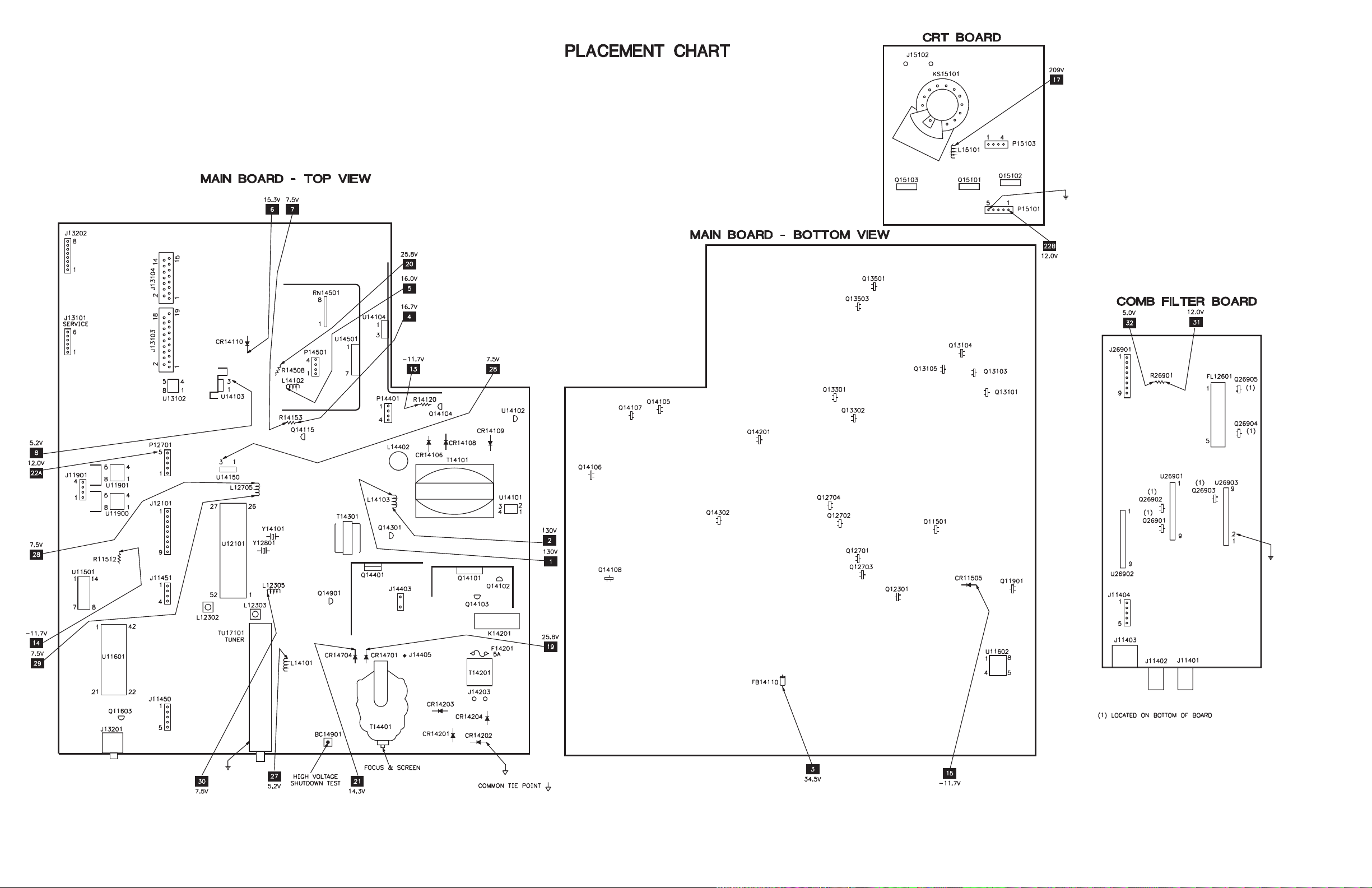
Placement Chart ..................................... 1
Safety Precautions.................................. 1
Schematic Component Location ............ 3
Schematic Notes ..................................... 2
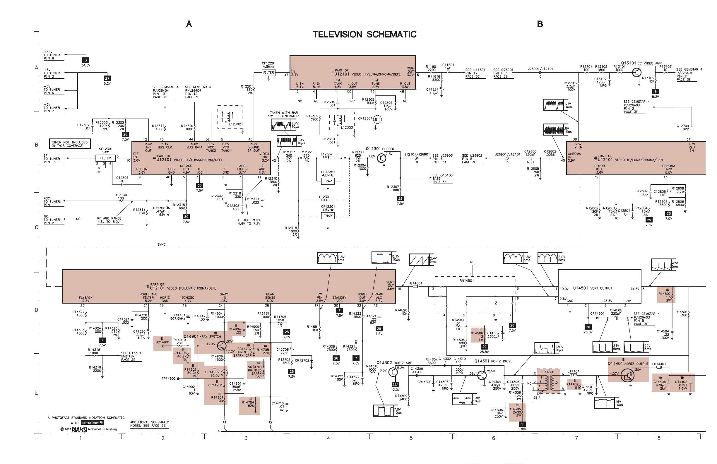
Schematics
Test Equipment....................................... 1
Tuner Information .................................. 1
INDEXINDEX
INDEX
INDEXINDEX
Main Board ..................................... 4
Audio ............................................... 3
Comb Filter ..................................... 3
Gemstar 4 ........................................ 3
Power Supply .................................. 2
Television ........................................ 2
Technical Service Data
RCARCA
RCA
RCARCA
Model G27648YX1 (Chassis CTC203AA)Model G27648YX1 (Chassis CTC203AA)
Model G27648YX1 (Chassis CTC203AA)
Model G27648YX1 (Chassis CTC203AA)Model G27648YX1 (Chassis CTC203AA)
Representative Model
ff
or seror ser
f
or ser
ff
or seror ser
Essential coEssential co
Essential co
Essential coEssential co
vicing a televicing a tele
vicing a tele
vicing a televicing a tele
ScSc
hematicshematics
•
Sc
hematics
ScSc
hematicshematics
veravera
gg
vera
veravera
vision receivervision receiver
vision receiver
vision receivervision receiver
ee
g
e
gg
ee
......
...
......
4733
4733
HIGH HIGH
VV
OLOL
TT
AA
HIGH
V
HIGH HIGH
VV
Momentarily short BC14901 (see Q14901 base) to ground. The receiver should lose raster and sound. If
receiver does not lose raster and sound, the shutdown circuit should be repaired. To resume normal
operation, remove AC power for approximately 30 seconds and then turn the receiver on.
The listing of any available replacement part herein in no case constitutes a recommendation, warranty, or guarantee by
SAMS Technical Publishing as to the quality and suitability of such replacement part. The numbers of the listed parts have
been compiled from information furnished to SAMS Technical Publishing by the manufacturers of the specific type of
replacement part listed.
Reproduction or use, without express permission, of editorial or pictorial content, in any manner, is prohibited. No patent
liability is assumed with respect to the use of the information contained herein.
© 2003 SAMS Technical Publishing LLC
9850 East 30th Street
Indianapolis, IN 46229
Printed in the United States of America 5 4 3 2 1
PP
aa
gg
e 1e 1
a
g
e 1
aa
gg
e 1e 1
SET 4733 SET 4733
SET 4733
SET 4733 SET 4733
P
PP
GE SHUTDOGE SHUTDO
OL
T
A
GE SHUTDO
OLOL
TT
AA
GE SHUTDOGE SHUTDO
WN WN
TESTTEST
WN
TEST
WN WN
TESTTEST
03PF02123
UPC
HERE
MODEL G27648YX1 (CHASSIS CTC203AA)MODEL G27648YX1 (CHASSIS CTC203AA)
MODEL G27648YX1 (CHASSIS CTC203AA)MODEL G27648YX1 (CHASSIS CTC203AA)
MODEL G27648YX1 (CHASSIS CTC203AA)
RCARCA
RCARCA
RCA
For Supplier AdFor Supplier Ad
For Supplier Ad
For Supplier AdFor Supplier Ad
See PHOSee PHO
See PHO
See PHOSee PHO
TT
T
TT
OFOF
OF
OFOF
AA
CT AnnCT Ann
A
CT Ann
AA
CT AnnCT Ann
dress,dress,
dress,
dress,dress,
ual Indeual Inde
ual Inde
ual Indeual Inde
xx
x
xx
Component locationsComponent locations
•
Component locations
Component locationsComponent locations
PP
arar
ts listts list
•
P
ar
ts list
PP
arar
ts listts list
Coverage includes these additional models and chassis:
ModelsModels
Models
ModelsModels
G27648YX51 CTC203AA5
G27648YX51 CTC203AA9
G27648YX52 CTC203AA5
G27648YX52 CTC203AA9
JUNE JUNE
2003 SET 4733 2003 SET 4733
JUNE
2003 SET 4733
JUNE JUNE
2003 SET 4733 2003 SET 4733
ChassisChassis
Chassis
ChassisChassis
Page 3
PP
aa
gg
e 1e 1
g
e 1
gg
e 1e 1
SET 4733 SET 4733
SET 4733
SET 4733 SET 4733
P
a
PP
aa
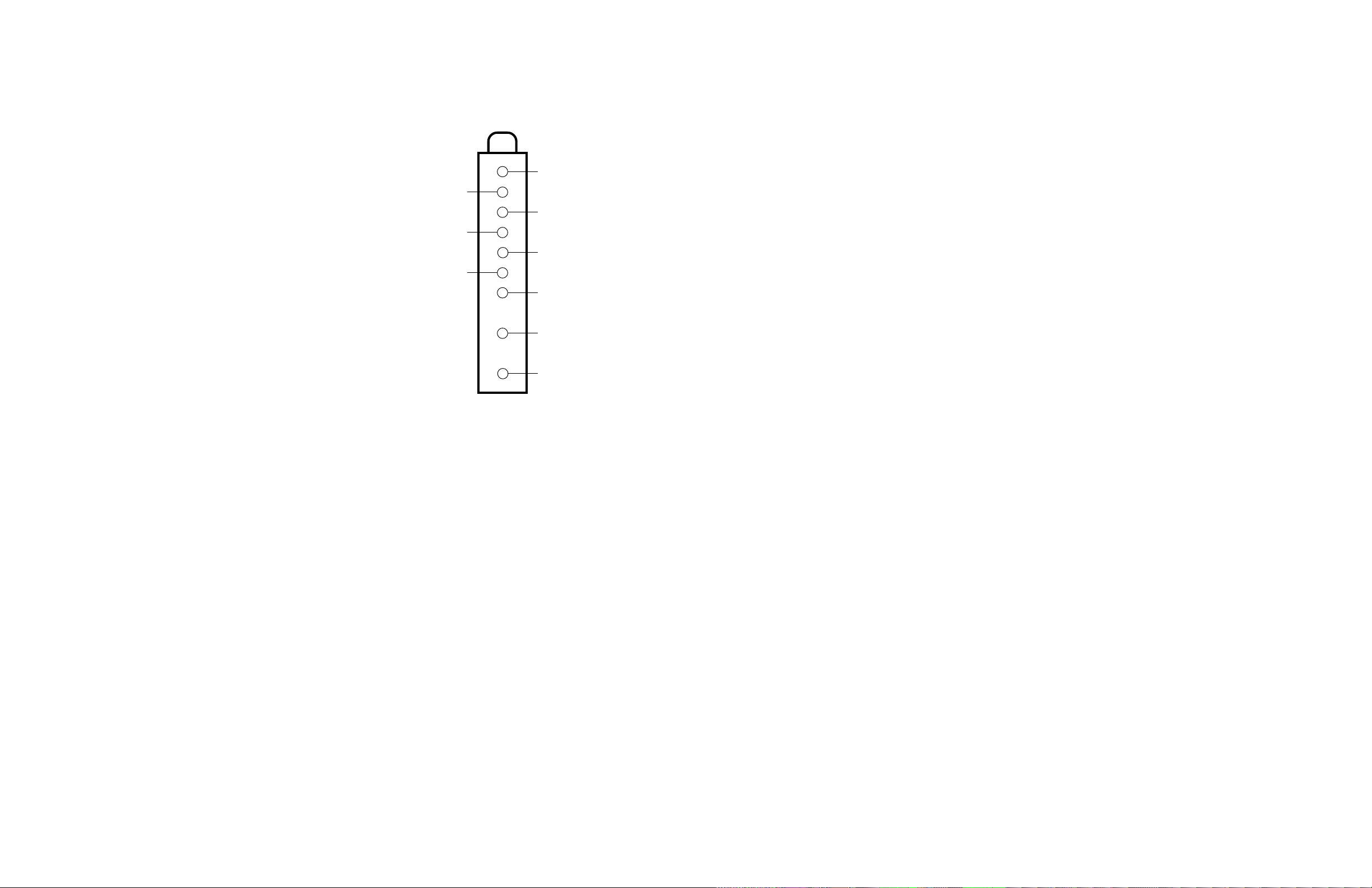
TUNER INFORMATION
TUNER TUNER
TUNER
TUNER TUNER
PinPin
Pin
PinPin
(1) AGC 2.5V 2.5V 3.0V
(2) NC 1.3V 4.3V 5.7V
(3) +5V 5.2V 5.2V 5.2V
(4) CLOCK 5.1V 5.1V 5.1V
(5) DATA 5.1V 5.1V 5.1V
(6) +5V 5.2V 5.2V 5.2V
(7) +5V 5.2V 5.2V 5.2V
(9) +32V 34.5V 34.5V 34.5V
(11) IF 0V 0V 0V
NOTE: VHF Low Band voltages taken on channel 2.
VHF LoVHF Lo
VHF Lo
VHF LoVHF Lo
VHF High Band voltages taken on channel 7.
UHF Band voltages taken on channel 14.
w Bandw Band
w Band
w Bandw Band
VV
OLOL
TT
V
OL
T
VV
OLOL
TT
AA
GE CHARGE CHAR
A
GE CHAR
AA
GE CHARGE CHAR
VHF High BandVHF High Band
VHF High Band
VHF High BandVHF High Band
TT
T
TT
UHF BandUHF Band
UHF Band
UHF BandUHF Band
TUNER TUNER
TUNER
TUNER TUNER
(2)
(4)
(6)
TERMINAL GUIDETERMINAL GUIDE
TERMINAL GUIDE
TERMINAL GUIDETERMINAL GUIDE
(1)
t
t
(3)
t
t
(5)
t
t
(7)
t
(9)
t
(11)
t
MISCELLANEOUS ADJUSTMENTS
NOTE: All procedures require an antenna connected and power applied
to the set.
HIGH HIGH
VV
OLOL
TT
AA
HIGH
V
HIGH HIGH
VV
Tune in a picture. Set brightness, contrast, and color to minium. Connect
a high voltage probe to the CRT anode. High voltage should measure
between 26kV and 28kV.
SERSER
VICE MENUVICE MENU
SER
VICE MENU
SERSER
VICE MENUVICE MENU
The following adjustment procedures are accessed thru a service menu. To access the service menu, turn the receiver on, press the menu button
and hold it down while pressing the power button. While holding down the menu button, release the power button and press the volume +
button. The screen will display a one line menu, on the left the parameter P0, and on the right the value of that parameter V0. Release buttons.
Adjustments are made by selecting the proper parameter and changing the value of that parameter. To change the parameter number use channel
up and down buttons. To adjust the current value of that parameter use volume + and - buttons. To access and change any of the adjustments, the
proper parameter pass number must be entered. This information is listed at the beginning of the alignment. When these parameters are
modified, the T-Chip and the corresponding EEPROM are updated. All service adjustments are bus controlled, except focus and screen.
NOTE: In order to adjust the RF AGC, audio or video levels, tuner, PIP, or stereo circuits, the ChipperCheck hardware and software must be
used. This can be purchased from Thomson Electronics. Before making any changes to any of the values, record the On Set values.
SERSER
VICE ADJUSTMENT PARAMETERSVICE ADJUSTMENT PARAMETERS
SER
VICE ADJUSTMENT PARAMETERS
SERSER
VICE ADJUSTMENT PARAMETERSVICE ADJUSTMENT PARAMETERS
PP
arameterarameter
P
arameter
PP
arameterarameter
No.No.
No.
No.No.
GE CHECKGE CHECK
OL
T
A
GE CHECK
OLOL
TT
AA
GE CHECKGE CHECK
PP
arameter Namearameter Name
P
arameter Name
PP
arameter Namearameter Name
On SetOn Set
On Set
On SetOn Set
VV
aluealue
V
alue
VV
aluealue
VV
aluealue
V
alue
VV
aluealue
RangRang
Rang
RangRang
COLOR COLOR
COLOR
COLOR COLOR
NOTE: See Service Adjustment Parameters to change drive and bias
values.
Press menu button for collapsed raster service line. Disconnect the
antenna. Preset the red, green, and blue drive values to 32. Adjust
screen control for a service line that is just visible. Adjust red,
green, and blue drives to obtain a white raster. Check the low light
to high light gray scale tracking. Repeat the procedure, if necessary, to obtain the best performance.
ee
e
ee
TEMPERATEMPERA
TEMPERA
TEMPERATEMPERA
CommentComment
Comment
CommentComment
TURETURE
TURE
TURETURE
0 Pass number for service Must set to 76 - May not advance until value is set to 76.
adjustment parameters.
1 Error Code 1 0 0 - 255 Displays the first error detected. Set to 0 before exiting.
See Error Codes Chart.
2 Error Code 2 0 0 - 255 Displays the second error detected. Set to 0 before exiting.
See Error Codes Chart.
3 Error Code 3 0 0 - 255 Displays the last error detected. Set to 0 before exiting.
See Error Codes Chart.
4 Horizontal Phase 10 0 - 15 Tune in a crosshatch pattern, adjust to center the pattern on
the screen.
5 EW DC (Width) 16 0 - 31 Tune in a crosshatch pattern, adjust for slight horizontal
overscan.
6 EW Amplitude 8 0 - 15 Set value to 8.
7 EW Tilt 8 0 - 15 Set value to 8.
8 Top Corner Pin Correction 2 0 - 7 Set value to 2.
9 Bottom Corner Pin Correction 2 0 - 7 Set value to 2.
10 Vertical DC 33 0 - 63 Tune in a crosshatch pattern, adjust to center vertically.
11 Vertical Size 84 0 - 127 Tune in a crosshatch pattern, adjust for slight vertical
overscan.
12 Vertical Countdown Mode 0 0 - 3 Set value to 0. ( 0 = Standard, 1 = Non-Standard, 2 = 50Hz,
3 = 48Hz )
13 Red Bias 30 0 - 127 Press menu button on the TV set for setup line.
14 Green Bias 15 0 - 127 Press menu button on the TV set for setup line.
15 Blue Bias 34 0 - 127 Press menu button on the TV set for setup line.
16 Red Drive 41 0 - 63 17 Green Drive 33 0 - 63 18 Blue Drive 32 0 - 63 19 Gemstar Horizontal OSD Position 166 0 - 255 Set value to 166.
20 Gemstar Vertical OSD Position 68 0 - 255 Set value to 68.
21 Gemstar PIP Horizontal Position 40 0 - 255 Set value to 40.
22 Gemstar PIP Vertical Position 43 0 - 255 Set value to 43.
23 Gemstar PIP Window Vertical Size 3 0 - 13 Set value to 3.
Page 4

SET 4733 PSET 4733 P
SET 4733 P
SET 4733 PSET 4733 P
aa
gg
e 1e 1
a
g
e 1
aa
gg
e 1e 1
ERROR CODES CHART
ErrErr
or Codeor Code
Err
or Code
ErrErr
or Codeor Code
DECDEC
DEC
DECDEC
0 00 No error code 1 01 16.0V fault 16.0V STBY source is failing.
3 03 12.0V run fault 12.0V source is failing.
4 04 T4 Chip Run supply failed.
8 08 T4 Chip X-ray protection caused high voltage shutdown.
9 09 T4 Chip (POR) Power supply problem at (POR) power on reset.
10 0A F2 PIP module error (POR) Power supply problem at (POR) power on reset/PIP.
11 0B Stereo decoder (POR) Power supply problem at reset/Stereo decoder.
16 10 Run IIC Bus held low Run IIC clock or data held low.
18 12 Standby IIC Bus held low Standby IIC clock or data held low.
23 17 Gemstar 4 Board Guide fatal error on set using Gemstar 4 Board.
24 18 Gemstar 4 Board Watchdog error on set using Gemstar 4 Board.
25 19 Gemstar 4 Board Task monitor error on set using Gemstar 4 Board.
26 1A Gemstar 4 Board Task monitor error on set using Gemstar 4 Board.
32 20 Gemstar 4 Board CPU error on set using Gemstar 4 Board.
34 22 Gemstar 4 Board Gemstar fails to acknowledge.
44 2C F2 PIP module error F2PIP fails to acknowledge.
102 66 Octal DAC Octal DAC fails to acknowledge.
128 80 Stereo decoder Stereo decoder fails to acknowledge.
160 A0 Main or PIP tuner EEPROM Main or PIP tuner EEPROM fails to acknowledge.
186 BA T4 Chip T4 Chip fails to acknowledge.
196 C4 Main tuner PLL/DAC Main tuner PLL IC fails to acknowledge.
198 C6 Main tuner PLL/DAC Main tuner DAC IC fails to acknowledge.
ERRERR
OR CODESOR CODES
ERR
OR CODES
ERRERR
OR CODESOR CODES
HEX HEX
HEX
HEX HEX
ErrErr
or Locationor Location
Err
or Location
ErrErr
or Locationor Location
Condition IndicatedCondition Indicated
Condition Indicated
Condition IndicatedCondition Indicated
TEST EQUIPMENT
Test equipment listed by participating manufacturer illustrates
typical or equivalent equipment used by Sams engineers to obtain
measurements. This equipment is compatible with most types used
by field service technicians.
EquipmentEquipment
Equipment
EquipmentEquipment
Oscilloscope SC3100
Generators
RGB CM2125
Multiburst Signal VG91
Color Bar VG91
TV Stereo VG91
Digital VOM SC3100
Frequency Meter SC3100
Hi-Voltage Probe HP200
Accessory Probes TP212
Isolation Transformer PR570
Capacitance Analyzer LC102
CRT Analyzer CR7000
AC Leakage Tester PR570
Inductance Analyzer LC102
Flyback Y oke Tester TV A92
Field Strength Meter SL753
Transistor Tester TF46
Horizontal Analyzer HA-2500
Video Analyzer VG91, TVA92
Sencore No.Sencore No.
Sencore No.
Sencore No.Sencore No.
If certain failures occur, the matching error codes will be stored in the EEPROM. These error codes will be displayed in parameters 1, 2, and 3. The first
failure error code will be stored at parameter 1 and the second failure error code will be stored at parameter 2. Parameter 3 will be updated to display the
most recent failure occurred in the chassis. If a failure of a bus IC occurred, the normal acknowledgment checking of that bus will be disabled in the
service mode and the address of that IC which failed will be stored in one of the error code parameters. After every repair is done to the chassis it is
recommended to check the error code parameters, and reset them back to value 0.
Page 5
RCA MODEL G27648YX1 (CHASSIS CTC203AA)
RCA MODEL G27648YX1 (CHASSIS CTC203AA)RCA MODEL G27648YX1 (CHASSIS CTC203AA)
RCA MODEL G27648YX1 (CHASSIS CTC203AA)RCA MODEL G27648YX1 (CHASSIS CTC203AA)
SET 4733 PSET 4733 P
SET 4733 P
SET 4733 PSET 4733 P
aa
gg
e 1e 1
a
g
e 1
aa
gg
e 1e 1
Page 6
PP
aa
gg
e 2e 2
g
gg
e 2
e 2e 2
SET 4733 SET 4733
SET 4733
SET 4733 SET 4733
P
a
PP
aa
Page 7
SET 4733 PSET 4733 P
SET 4733 P
SET 4733 PSET 4733 P
aa
gg
e 2e 2
a
g
e 2
aa
gg
e 2e 2
Page 8
PP
aa
gg
e 2e 2
a
g
e 2
aa
gg
e 2e 2
SET 4733 SET 4733
SET 4733
SET 4733 SET 4733
P
PP
Page 9
RCA MODEL G27648YX1 (CHASSIS CTC203AA)
RCA MODEL G27648YX1 (CHASSIS CTC203AA)RCA MODEL G27648YX1 (CHASSIS CTC203AA)
RCA MODEL G27648YX1 (CHASSIS CTC203AA)RCA MODEL G27648YX1 (CHASSIS CTC203AA)
SET 4733 PSET 4733 P
SET 4733 P
SET 4733 PSET 4733 P
aa
gg
e 2e 2
a
g
e 2
aa
gg
e 2e 2
Page 10

PP
aa
gg
e 3e 3
a
g
e 3
aa
gg
e 3e 3
SET 4733 SET 4733
SET 4733
SET 4733 SET 4733
P
PP
Page 11

SET 4733 PSET 4733 P
SET 4733 P
SET 4733 PSET 4733 P
aa
gg
e 3e 3
a
g
e 3
aa
gg
e 3e 3
Page 12

PP
aa
gg
e 3e 3
a
g
e 3
aa
gg
e 3e 3
SET 4733 SET 4733
SET 4733
SET 4733 SET 4733
SET 4733 PSET 4733 P
SET 4733 P
SET 4733 PSET 4733 P
aa
gg
e 3e 3
a
g
e 3
aa
gg
e 3e 3
P
PP
Page 13

SCHEMASCHEMA
SCHEMA
SCHEMASCHEMA
TIC COMPONENT LOCATIC COMPONENT LOCA
TIC COMPONENT LOCA
TIC COMPONENT LOCATIC COMPONENT LOCA
TION GUIDETION GUIDE
TION GUIDE
TION GUIDETION GUIDE
C3401 A45
C11401 E31
C11402 D31
C11403 B29
C11450 B38
C11451 B38
C11453 C43
C11454 C43
C11455 C43
C11456 C43
C11501 D40
C11502 D40
C11503 D43
C11504 D43
C11506 D38
C11507 E38
C11601 A5
C11602 C38
C11603 C38
C11604 C40
C11605 D40
C11606 C40
C11607 C40
C11608 B38
C11609 B38
C11610 C38
C11611 B38
C11612 D38
C11613 D38
C11614 C38
C11615 C38
C11616 C37
C11617 A38
C11618 D38
C11619 E38
C11620 C40
C11621 B40
C11622 B40
C11623 D40
C11624 A5
C11625 D40
C11626 A39
C11627 A39
C11628 A41
C11629 B39
C11630 A41
C11631 A41
C11632 A38
C11633 A38
C11701 E37
C11702 D38
C11703 D38
C11704 E38
C11705 E38
C11906 A42
C11907 B42
C11908 C43
C11909 B43
C11910 A42
C11912 B42
C11913 A44
C11914 B44
C12301 C1
C12302 B1
C12303 D45
C12304 A4
C12305 A5
C12306 C2
C12307 C3
C12308 C3
C12310 B4
C12312 C28
C12313 C3
C12314 C28
C12601 B32
C12602 B32
C12701 A7
C12702 C10
C12703 C10
C12704 C9
C12706 D4
C12707 C28
C12708 C28
C12709 B8
C12710 B9
C12711 B11
C12712 A28
C12713 C10
C12714 C13
C12715 B13
C12716 B13
C12717 C9
C12718 C10
C12801 C8
C12802 B7
C12803 C9
C12805 B6
C12806 C8
C12807 C8
C13102 A7
C13114 D46
C13119 B52
C13141 C46
C13163 C24
C13205 B50
C13501 D46
C13502 D46
C13503 C45
C13504 C45
C14101 B19
C14102 B20
C14103 C19
C14104 C19
C14105 C19
C14106 C20
C14107 C20
C14108 A20
C14109 A22
C14110 A24
C14111 B23
C14112 B23
C14113 B21
C14114 B24
C14115 C21
C14116 D23
C14118 A28
C14119 B24
C14121 B24
C14122 A24
C14124 A22
C14125 B20
C14126 C19
C14127 C20
C14150 C27
C14151 C26
C14152 B24
C14153 B24
C14154 B27
C14155 B28
C14158 B24
C14159 B23
C14160 B27
C14201 A17
C14203 A19
C14204 A19
C14205 A20
C14206 A20
C14206 A20
C14207 C17
C14208 A17
C14209 A18
C14210 A18
C14211 B18
C14212 C17
C14213 C17
C14302 E5
C14303 E5
C14304 E6
C14305 E6
C14306 E6
C14309 E5
C14310 E5
C14320 D2
C14321 D2
C14322 E4
C14401 E7
C14402 E8
C14403 D9
C14404 D9
C14405 D10
C14406 E8
C14502 D6
C14504 D8
C14505 D7
C14506 E21
C14507 E21
C14521 D5
C14701 E20
C14702 D19
C14703 D19
C14704 D19
C14706 E20
C14710 E3
C14711 E21
C14901 E3
C14902 E2
C14903 D3
C14904 D3
C15101 D15
C17416 C51
C17417 C51
C26901 D28
C26902 D27
C26905 C32
C26905A D27
C26906 E33
C26907 B33
C26908 B33
C26910 C28
C26911 D28
C26915 B29
C26916 C30
C26917 D27
CF12201 A3
CF12301 C4
CF12351 B4
CR11401 B29
CR11402 E32
CR11403 D32
CR11501 D41
CR11502 D41
CR11503 D43
CR11504 D23
CR11505 D24
CR11601 B41
CR11602 C37
CR11603 C37
CR12301 B5
CR12702 E4
CR13501 D46
CR14101 B18
CR14102 B18
CR14103 C19
CR14104 C19
CR14105 C18
CR14106 A22
CR14107 B23
CR14108 B21
CR14109 B21
CR14110 B23
CR14111 D21
CR14113 E24
CR14114 E24
CR14115 C27
CR14117 C19
CR14201 A19
CR14202 A19
CR14203 A19
CR14204 A19
CR14205 B18
CR14210 A19
CR14301 E5
CR14401 D10
CR14501 D7
CR14701 E19
CR14702 D19
CR14704 E20
CR14901 E3
CR14902 E3
CR26901 D27
CR26902 D27
DY1 D9
F14201 A17
FB13201 B50
FB14106 B22
FB14107 A22
FB14108 A22
FB14109 B20
FB14110 A24
FB14114 B21
FB14401 E8
FB14501 D5
FL12601 B32
IR3401I A45
J11401 B37
J11401 B37
J11401 C29
J11402 C44
J11402 C44
J11403 D30
J13201 B51
K14201 A18
K14201 B18
L12301 C4
L12302 B3
L12303 B4
L12305 C27
L12352 B4
L12705 C27
L14101 B28
L14102 B22
L14103 A24
L14105 A23
L14200 A18
L14401 E7
L14402 D9
L15101 D21
L26901 C26
PW14201 A17
Q11501 D23
Q11603 C38
Q11901 C41
Q12301 B5
Q12701 C13
Q12702 A13
Q12703 B13
Q12704 B13
Q13101 A8
Q13103 D46
Q13104 B51
Q13105 B51
Q13301 E46
Q13302 E46
Q13501 D46
Q13503 C46
Q14101 B20
Q14102 B19
Q14103 C19
Q14104 A25
Q14105 A25
Q14106 D21
Q14107 D21
Q14108 B19
Q14115 B27
Q14201 B17
Q14301 E6
Q14302 E5
Q14401 E7
Q14901 D3
Q15101 A14
Q15102 C14
Q15103 B14
Q26901 D35
Q26902 D31
Q26903 B29
Q26904 C30
Q26905 C31
R3401 A45
R3402 A46
R3404 A46
R5050 D12
R11401 B37
R11402 B38
R11403 B37
R11404 B38
R11405 C29
R11406 B29
R11407 C44
R11408 C44
R11409 C44
R11410 D44
R11411 E31
R11412 E31
R11413 D31
R11414 D31
R11460 B38
R11461 B38
R11462 C43
R11463 C43
R11501 D40
R11502 D40
R11503 D40
R11504 D40
R11505 D41
R11506 D40
R11507 D41
R11508 D42
R11509 D42
R11510 D42
R11511 D38
R11512 E38
R11513 D23
R11514 D23
R11601 A5
R11602 D39
R11603 C39
R11604 C39
R11605 B38
R11606 D38
R11607 D38
R11608 D38
R11609 D38
R11611 A40
R11612 A40
R11613 B40
R11614 A41
R11615 C38
R11616 C38
R11617 B38
R11618 A5
R11619 C37
R11620 C37
R11621 B40
R11622 B40
R11623 B41
R11624 B41
R11625 A41
R11626 A41
R11627 C38
R11628 A38
R11629 A38
R11630 A38
R11631 A38
R11701 D37
R11702 E37
R11703 D37
R11704 D38
R11705 D38
R11706 E38
R11707 E39
R11708 D37
R11709 E37
R11909 C43
R11910 A42
R11911 A42
R11912 B42
R11913 B42
R11915 B41
R11917 C41
R11918 C41
R11919 C41
R11920 A44
R11921 B44
R12201 A3
R12302 B2
R12303 B1
R12304 B4
R12305 D45
R12306 E24
R12307 C5
R12308 A5
R12309 B4
R12310 B3
R12311 B4
R12314 C2
R12315 C2
R12316 C3
R12317 B3
R12318 C4
R12351 B4
R12601 B32
R12701 C10
R12702 E4
R12703 C10
R12704 A7
R12705 C9
R12706 C12
R12707 A12
R12708 B12
R12710 B2
R12711 B2
R12712 B12
R12713 B12
R12714 B10
R12715 C13
R12716 C13
R12717 C13
R12718 C13
R12719 A13
R12720 A13
R12721 A13
R12722 A13
R12723 B13
R12724 B13
R12725 B13
R12726 C10
R12727 B13
R12731 D3
R12801 C7
R12802 C7
R12803 C9
R12804 C8
R12805 B7
R12806 C8
R12807 C8
R12808 C8
R13101 A7
R13102 A8
R13103 A8
R13108 A7
R13109 D46
R13110 D45
R13111 D46
R13112 D46
R13113 C46
R13118 B47
R13119 B47
R13121 D46
R13122 A46
R13123 D46
R13124 C45
R13125 C45
R13126 B47
R13128 B51
R13130 C50
R13131 B50
R13134 A51
R13135 A51
R13136 B51
R13139 A52
R13142 A51
R13143 C50
R13144 D50
R13165 E51
R13166 B51
R13169 C50
R13176 B51
R13180 B51
R13181 B50
R13182 B50
R13183 D43
R13185 D44
R13188 C46
R13189 B46
R13190 B46
R13191 B46
R13192 D51
R13198 E51
R13203 B50
R13314 E46
R13315 E45
R13316 E46
R13317 E46
R13318 E46
R13319 E45
R13320 E45
R13321 E46
R13322 E46
R13501 D45
R13503 D46
R13504 D46
R13505 C46
R13508 C45
R13510 C46
R13511 C45
R13512 C45
R14101 B18
R14102 B18
R14103 B19
R14104 B19
R14105 C20
R14106 B19
R14107 B19
R14108 C20
R14109 C19
R14110 C19
R14111 C19
R14112 C19
R14113 C20
R14114 D20
R14115 D20
R14116 D20
R14117 A20
R14118 A24
R14119 A23
R14120 D23
R14121 E52
R14122 A25
R14123 A25
R14124 B22
R14126 D20
R14127 D21
R14128 D22
R14129 C20
R14130 D23
R14132 D22
R14135 D20
R14151 C26
R14153 B23
R14155 B27
R14157 B27
R14158 B27
R14159 B27
R14201 A17
R14202 A18
R14204 A20
R14205 A17
R14206 B17
R14303 D1
R14304 E5
R14305 E6
R14306 E6
R14309 E5
R14310 E4
R14318 E1
R14319 E1
R14320 D2
R14321 D4
R14322 E4
R14323 D4
R14324 D1
R14326 D1
R14327 D1
R14328 D4
R14401 D10
R14402 E7
R14403 E10
R14501 D8
R14503 D5
R14504 D6
R14506 D6
R14507 D8
R14508 E20
R14509 E21
R14520 D5
R14701 D19
R14702 D20
R14703 A16
R14704 E3
R14705 E3
R14706 D3
R14851 D4
R14901 E3
R14902 E2
R14903 E2
R14904 D3
R14906 E3
R14909 D3
R14910 D2
R15101 A15
R15102 C15
R15103 B15
R15104 A15
R15105 C15
R15106 B15
R15107 A14
R15108 C14
R15109 B14
R15118 D16
R17130 C1
R17402 B51
R17403 C51
R17409 C51
R17411 C51
R26901 D27
R26902 D31
R26903 E33
R26904 E32
R26905 D31
R26906 D32
R26907 D32
R26908 D33
R26910 D32
R26910A D27
R26911 D33
R26912 B33
R26913 B33
R26915 B30
R26916 D35
R26917 D36
R26921 B30
R26922 B30
R26923 B29
R26924 B30
R26925 B29
R26926 C30
R26927 B30
R26928 C30
R26929 C31
R26930 C31
RN14501 D5
RT14201 A18
SF12301 B1
SP1 A44
SP2 B44
SW3410I B45
SW3412I B45
SW3420I B45
SW3421I B45
SW3430I B45
SW3431I B45
T14101 A21
T14201 A17
T14301 E7
T14401 D11
T14401 E18
U11501 D37
U11501 D41
U11501 D42
U11501 E37
U11601 A39
U11602 A41
U11602 B41
U11900 A43
U11901 B43
U12101 A4
U12101 B2
U12101 B7
U12101 D2
U13102 A52
U14101 C19
U14102 D19
U14103 C23
U14104 A26
U14150 C27
U14501 D7
U26901 C34
U26902 A34
U26903 A31
V101 C16
Y12801 B9
Y14101 D2
RCA MODEL G27648YX1 (CHASSIS CTC203AA)
RCA MODEL G27648YX1 (CHASSIS CTC203AA)RCA MODEL G27648YX1 (CHASSIS CTC203AA)
RCA MODEL G27648YX1 (CHASSIS CTC203AA)RCA MODEL G27648YX1 (CHASSIS CTC203AA)
SET 4733 PSET 4733 P
SET 4733 P
SET 4733 PSET 4733 P
aa
gg
e 3e 3
a
g
e 3
aa
gg
e 3e 3
Page 14

PP
aa
gg
e 4e 4
g
e 4
gg
e 4e 4
SET 4733 SET 4733
SET 4733
SET 4733 SET 4733
P
a
PP
aa
MAIN BOMAIN BO
MAIN BO
MAIN BOMAIN BO
ARDARD
ARD
ARDARD
MAIN BOMAIN BO
MAIN BO
MAIN BOMAIN BO
BC14901 O7
C11450 O3
C11451 O3
C11453* O3
C11454* O3
C11455* O3
C11456* N3
C11501* K2
C11502* K2
C11503* K1
C11504 K1
C11506 K1
C11507 J2
C11601 N2
C11602 N2
C11603 N2
C11604 M3
C11605* M3
C11606* M3
C11607* M3
C11608* M2
C11609* M2
C11610* M2
C11611 M2
C11612* M1
C11613* M2
C11614 N2
C11615* N2
C11616 N2
C11617 N3
C11618 M2
C11619 N3
C11620 M3
C11621* L2
C11622* L2
C11623 M3
C11624 N1
C11625* L2
C11626* L2
C11627* M2
C11628 L1
C11629* L2
C11630 K2
C11631* L1
C11701* J2
C11702* K2
C11703 K2
C11704* J3
C11705 J2
C11906* I2
C11907* H2
C11908 I2
C11909 H2
C11910* H2
C11912* G2
C11913 I1
C11914 G1
C12301* J5
C12302* J5
C12303* J4
C12304* K5
C12305 K5
C12306 N6
C12307* J5
C12308* J5
C12310 K5
C12312* K5
C12313* J5
C12314 K6
C12701 I4
C12702 I4
C12703 H5
C12704 H3
ARDARD
ARD
ARDARD
,,
GRIDTRA GRIDTRA
,
GRIDTRA
,,
GRIDTRA GRIDTRA
C12706 F6
C12707 H5
C12708* H5
C12709* I4
C12710* I4
C12711* I4
C12712* G3
C12713 H4
C12714* G4
C12715* G4
C12716* H4
C12717* J5
C12718* I5
C12801* I5
C12802* J4
C12803* J5
C12805* J4
C12806 J6
C12807* J5
C13102* E1
C13114* D2
C13119* E3
C13141* C4
C13163* F5
C13205* O1
C13501* B4
C13502* B3
C13503* B3
C13504* B4
C14101 K11
C14102 H10
C14103* K11
C14104 J12
C14105 J12
C14106* H11
C14107* F12
C14108 I11
C14109 F10
C14110 E10
C14111 D12
C14112 D11
C14113 F11
C14114 F11
C14115 F11
C14116 E11
C14118 E9
C14119 F5
C14121 F12
C14122 H9
C14124 F10
C14125 I11
C14126* I12
C14127* I12
C14150 H5
C14151 H5
C14152 H6
C14153* I5
C14154* F6
C14155 O5
C14158 L6
C14159* L6
C14160* M6
C14201 M12
C14203 O10
C14204 O11
C14205 L10
C14206 M10
C14207 O11
C14208 N12
C14302* G8
C14303* G8
C14304 H8
C14305 H8
CE LOCACE LOCA
CE LOCA
CE LOCACE LOCA
C14306 H8
C14309* G8
C14310 G8
C14320 I6
C14321* I5
C14322* I6
C14401* J8
C14402 K8
C14403 F8
C14404 F7
C14405 F9
C14406 J8
C14502 B7
C14504 B6
C14505 C7
C14506 C7
C14507* C7
C14521 H5
C14701 M7
C14702* M8
C14703 E9
C14704 E8
C14706* M8
C14710 N10
C14711 L8
C14901 E8
C14902 E8
C14903* I5
C14904* K6
C17416* L4
C17417* L4
CF12201 J4
CF12351 J4
CR11501* J1
CR11502* K1
CR11503 K1
CR11504 G2
CR11505* J2
CR11601* L1
CR11602 N2
CR11603* O2
CR12301* K5
CR12702 G6
CR13501 B3
CR14101 K10
CR14102 K11
CR14103 H12
CR14104 H12
CR14105 J11
CR14106 F10
CR14107 D12
CR14108 F10
CR14109 F11
CR14110 D5
CR14111 E11
CR14113* P3
CR14114* P3
CR14115 F6
CR14117 I12
CR14201 O10
CR14202 O11
CR14203 N10
CR14204 N11
CR14205 D11
CR14301 G8
CR14401 F8
CR14501 C7
CR14701 M8
CR14702 F8
CR14704 M8
CR14901 E7
CR14902 J7
F14201 L11
TION GUIDETION GUIDE
TION GUIDE
TION GUIDETION GUIDE
FB13201 O1
FB14106 F10
FB14107 F10
FB14108 F10
FB14109 I11
FB14110 L5
FB14114 F10
FB14401 J8
FB14501 I6
J11403 L9
J11450 N3
J11901 H1
J13103 E3
J13104 C3
J13201 O1
J13202 C1
J14405 M9
K14201 K11
L12301* J4
L12302 K4
L12303 K5
L12352 J6
L12705 H5
L14101 M6
L14102 D6
L14103 G9
L14105 D11
L14401 I8
L14402 F9
P12701 G3
P14401 D8
P14501 D6
Q11501* G2
Q11603 O2
Q11901* J1
Q12301* J4
Q12701* H4
Q12702* G4
Q12703* H4
Q12704* G4
Q13101* E2
Q13103* D2
Q13104* D2
Q13105* D2
Q13301* D4
Q13302* D4
Q13501* B3
Q13503* B4
Q14101 J11
Q14102 J11
Q14103 J11
Q14104 D10
Q14105* D10
Q14106* E12
Q14107* D11
Q14108* K11
Q14115 E6
Q14201* D7
Q14301 H9
Q14302* G8
Q14401 J8
Q14901 K7
R11460* O3
R11461* O3
R11462* O3
R11463* O3
R11501* K3
R11502* K3
R11503* K1
R11504* K3
R11505* K1
R11506* K3
R11507* K1
R11508* K1
R11509* K1
R11510* K1
R11511 J1
R11512 J2
R11513* G2
R11514* G2
R11601* N2
R11602* M3
R11603* M3
R11604* M3
R11605* M2
R11606* M2
R11607* M2
R11608* M1
R11609* M2
R11611* M1
R11612* L2
R11613* L1
R11614* L2
R11615* N2
R11616* N2
R11617* M2
R11618* N2
R11619* O2
R11620* O2
R11621* M1
R11622* L1
R11623* L1
R11624* L1
R11625* L1
R11626* K2
R11627 F2
R11701* K2
R11702* K2
R11703* K2
R11704* K2
R11705 K2
R11706* J3
R11707 K2
R11708* K2
R11709* K2
R11909 G2
R11910* I2
R11911* I2
R11912* H2
R11913* H2
R11915* J1
R11917 F2
R11918* J1
R11919* J1
R11920* I1
R11921* G1
R12201* J4
R12302* J6
R12303* J5
R12304* J4
R12305* J4
R12306* J5
R12307* J3
R12308* K5
R12309* K5
R12311* J4
R12314* K5
R12315* K5
R12316* J5
R12317* K4
R12318* K4
R12351* K4
R12701* I4
R12702 G5
R12703* I4
R12704 I3
R12705* J5
R12706* I4
R12707* I4
R12708* I4
R12710 K4
R12711 K4
R12712* G4
R12713* G4
R12714* I4
R12715* H4
R12716* G4
R12717 G4
R12718* G3
R12719* G4
R12720* G4
R12721 G4
R12722* H3
R12723* I4
R12724* I4
R12725 G4
R12726* H4
R12727* G3
R12731 H4
R12801* I5
R12802* I5
R12803* J6
R12804* I4
R12805* J4
R12806* J6
R12807* J6
R12808* J6
R13101 D1
R13102 D2
R13103 D2
R13108 F3
R13109* E2
R13110* C2
R13111* E2
R13112* D2
R13113* B2
R13118 C2
R13119 C2
R13121* D4
R13122* E4
R13123 D4
R13124* C4
R13125 D4
R13126* C2
R13128* D2
R13130* B2
R13131* B2
R13134* E2
R13135* D2
R13136* E3
R13139* E2
R13142* E2
R13143 C4
R13144 C4
R13165* D2
R13166* B2
R13169* B2
R13176* E3
R13180* D2
R13181* D2
R13182* D2
R13183* D4
R13185* E4
R13188 B2
R13189 B2
R13190 B2
R13191 B2
R13192* C4
R13198* D3
R13203 O1
R13314* E4
R13315* D4
R13316* E4
R13317* E4
R13318* E4
R13319* D5
R13320 D5
R13321* F5
R13322 F4
R13501* B4
R13503* B4
R13504* B3
R13505* B3
R13508* B3
R13510* C4
R13511* B3
R13512* B3
R14101 J10
R14102 J10
R14103 K10
R14104 K11
R14105 H11
R14106 K11
R14107 J11
R14108 J11
R14109 J11
R14110 I11
R14111 I12
R14112* H11
R14113 F11
R14114* E12
R14115 E11
R14116 E12
R14117 I10
R14118 E11
R14119 D12
R14120 D9
R14121 E9
R14122 D10
R14123 D10
R14124 D9
R14126* E12
R14127* D10
R14128 E9
R14129* H1
R14130 F12
R14132* D11
R14151 G5
R14153 E6
R14155 E6
R14157 E6
R14158 F6
R14159 F6
R14201 N12
R14202 O11
R14204 M10
R14205 N12
R14206* D7
R14303 H6
R14304* G8
R14305 I8
R14306 H8
R14309 G8
R14310 H7
R14318 D6
R14319 D6
R14320* I6
R14321* G6
R14322* I6
R14323* I6
R14324* H6
R14326* I6
R14327* H6
R14401 G8
R14402 I7
R14403 G9
R14501 C6
R14503 B6
R14504 D7
R14506 D6
R14507 B6
R14508 D6
R14509 D7
R14520* I5
R14701 N7
R14702 E9
R14703 E7
R14704 O9
R14705 L9
R14706 G5
R14851* I5
R14901 E7
R14902 K7
R14903 N7
R14904 G6
R14906* J6
R14909* I6
R14910* N3
R17130* O6
R17402* L4
R17403* L4
R17409* M4
R17411* M4
RN14501 C7
RT14201 L11
SF12301 J6
T14101 G11
T14201 M11
T14301 H8
T14401 N9
TU17101 N4
U11501 J2
U11601 L2
U11602* L1
U11900 I2
U11901 H2
U12101 J5
U13102 E3
U14101 H12
U14102 E12
U14103 E5
U14104 C8
U14150 G5
U14501 C7
Y12801 I6
Y14101 I6
* Component
located on
bottom of
board.
Page 15

PARTS LIST
SET 4733 PSET 4733 P
SET 4733 P
SET 4733 PSET 4733 P
aa
gg
e 4e 4
a
g
e 4
aa
gg
e 4e 4
Item No.Item No.
Item No.
Item No.Item No.
CR11401 - 232710 CR11402 - 220638 NTE5014A
CR11403 - 232710 CR11501, 02 - 232709 CR11503 - 215488 NTE136A
CR11504 - 226463 CR11505 - 232709 CR11601 - 232709 -
# CR11602 - 159429 NTE5019T1
CR11603 - 232709 CR12301 - 227051 CR12702 - 198589 NTE519
CR13501 - 164874 NTE177
CR14101 - 232221 CR14102 - 198589 NTE519
CR14103, 04 - 139706 NTE177
CR14105 - 198589 NTE519
CR14106 - 243636 CR14107 - 217306 CR14108 - 243636 CR14109 - 176296 NTE552
CR14110 - 155276 NTE116
CR14111 - 198589 NTE519
CR14113, 14 - 232709 CR14115 - 215488 NTE136A
# CR14117 - 244224 -
CR14201 Thru
CR14204 - 147015 NTE125
CR14205 - 198589 NTE519
# CR14210 - 214649 NTE5331
CR14301 - 176296 NTE552
# CR14401 - 140971 NTE558
CR14501 - 155276 NTE116
CR14701 - 241304 CR14702 - 176296 NTE552
CR14704 - 207878 NTE519
# CR14901 - 157301 NTE177
# CR14902 - 159429 NTE5019T1
CR26901 - 198602 CR26902 - - Q11501 - 215495 Q11603 - 177788 NTE31
Q11901 - 215495 Q12301 - 215496 Q12701, 02, 03 - 215495 Q12704 - 215496 Q13101, 03, 04 - 215496 Q13105 - 215495 Q13301 - 215496 Q13302 - 215495 Q13501 - 215496 Q13503 - 215495 Q14101 - 244223 -
# Q14102 - 147665 NTE159
Q14103 - 232218 Q14104 - 243955 Q14105, 06, 07 - 215495 -
# Q14108 - 215496 -
TT
ype No.ype No.
T
ype No.
TT
ype No.ype No.
MfrMfr
Mfr
MfrMfr
..
P P
arar
t No.t No.
.
P
ar
t No.
..
P P
arar
t No.t No.
NTE PNTE P
NTE P
NTE PNTE P
arar
ar
arar
t No.t No.
t No.
t No.t No.
Item No.Item No.
Item No.
Item No.Item No.
Q14115 - 177788 NTE31
Q14201 - 219412 Q14301 - 146851 NTE287
Q14302 - 215495 -
# Q14401 - 242224 # Q14901 - 147665 NTE159
Q15101, 02, 03 - 215497 NTE2501
Q26901 - 215496 Q26902 Thru
Q26905 - 215495 U11501 MC3403N 241785 NTE987
U11601 CXA2074S 237930 U11602 - 237474 U11900, 01 TDA7267 244225 -
# U12101 LA7612N 252842 -
U13102 (1) - 251160 U13102 (2) - 251271 -
# U14101 - 223653 -
U14102 - 231525 U14103 L7852CV 241752 U14104 KA7812 162394 NTE966
U14150 L78S75CV 231526 U14501 (1) - 232109 NTE1788
U14501 (2) - 215531 NTE1788
U26901, 02, 03 LA7221 227354 -
Item No.Item No.
Item No.
Item No.Item No.
C11612, 13 22pF 5% 50V NPO 194903 C12303 120pF 5% 50V NPO 194902 C12714, 15, 16 470pF 5% 50V NPO 214732 C12718 100pF 5% 50V NPO 193340 C12803 15pF 5% 50V NPO 200538 C12805 120pF 5% 50V NPO 194902 C13102 120pF 5% 50V NPO 194902 -
C13205 220pF 5% 50V NPO 205551 -
# C14102 .0168 1.6kV 237355 -
# C14108 .0011 1.6kV 244208 -
# C14111 100µF 20% 63V 237425 -
# C14112 .01 10% 50V 240934 -
C14113, 15 680pF 20% 1kV 190538 C14159, 60 100pF 5% 50V NPO 193340 -
# C14201 .22 20% 250VAC - -
# C14203, 04 680pF 20% 1kV 190538 -
# C14205 680µF 20% 200V 190560 -
# C14207 .0034 20% 120V 223330 -
# C14208 470pF 250VAC 250102 -
# C14209 .1 20% 125V 229322 -
# C14210, 11 680pF 20% 1kV 190538 -
# C14212, 13 .01 20% 250VAC 252973 -
C14303 470pF 5% 50V NPO 214732 C14310 15pF 1% 250V NPO 223899 C14322 39pF 5% 50V NPO 202905 C14401 470pF 5% 50V NPO 214732 -
TT
ype No.ype No.
T
ype No.
TT
ype No.ype No.
LA7612A 241266 -
Function/RatingFunction/Rating
Function/Rating
Function/RatingFunction/Rating
120pF 5% 50V NPO 174414 -
220pF 5% 50V NPO 178188 -
.22 20% 125VAC 231451 -
470pF 5% 50V NPO 195918 -
MfrMfr
Mfr
MfrMfr
MfrMfr
Mfr
MfrMfr
..
P P
arar
t No.t No.
.
P
ar
t No.
..
P P
arar
t No.t No.
..
P P
arar
t No.t No.
.
P
ar
t No.
..
P P
arar
t No.t No.
NTE PNTE P
NTE P
NTE PNTE P
NotesNotes
Notes
NotesNotes
arar
ar
arar
t No.t No.
t No.
t No.t No.
Page 16

PARTS LIST continued
Item No.Item No.
Item No.
Item No.Item No.
# C14402 .0127 1.6kV 246497 -
# C14403 .41 5% 250V 214752 -
# C14404 2.2µF 20% 200V 247673 -
# C14405 .0047 10% 250V 142765 -
# C14406 470pF 5% 2kV 227068 -
C14702 470pF 10% 500V NPO 227050 C14704 680pF 20% 1kV 190538 C14706 470pF 10% 500V NPO 227050 C14710 .01 20% 1kV 137583 -
# C14904 .22 25V 217298 -
C15101 .001 10% 3kV 120696 C17416, 17 43pF 5% 50V NPO 214029 CF12201 Filter 195702 4.5MHz
CF12301 Trap 195702 4.5MHz
CF12351 Trap 181125 4.5MHz
#DY1 (3) Yoke - Horiz 1.3mH, Vert 18mH
# F14201 Fuse 175425 5A, 125V
FB13201 Ferrite Bead 226467 FB14106, 07, 08 Ferrite Bead 237504 FB14109, 10 Ferrite Bead 226467 FB14114 Ferrite Bead 237504 FB14401 Ferrite Bead 161237 FB14501 Ferrite Bead 215547 FL12601 Filter 225701 Comb
IR3401I Receiver 229219 IR
J11401 Jack 239389 Assembly
J11402 Jack 245283 Assembly
J11403 Socket 195705 S-Video Input
J13201 Socket 214609 Gemstar IR Output
# K14201 (1) Relay 256573 Degaussing
# K14201 (2) Relay 190490 Degaussing
# KS15101 Socket 233120 CRT
L12301 18µH 243894 L12302 VCO 215502 L12303 FM 233056 L12305 10µH 175409 L12352 18µH 195711 L12705 10µH 175409 L14101 100µH 160186 L14102 27µH 190017 L14103 22µH 215504 L14105 47µH 244222 -
# L14200 Degaussing 218764 -
L14401 6.8µH 191141 -
# L14402 Horizontal Linearity 192844 -
L15101 100µH 160186 -
# L26901 - 244249 -
# PW14201 Line Cord 241251 AC, Polarized
# R11401, 03 2200 5% 1/2W 246613 -
# R11406 56 247610 -
# R11407, 09 2200 20% 1/4W 237429 -
# R11412, 14 56 247610 -
# R11511, 12 100 5% 1/4W 198667 -
R11616 61.9K 1% 1/10W 225705 -
# R11627 10 5% 1/4W 241259 -
# R11909 16 5% 3W Nonflammable 244213 -
R12201 680 2% 1/10W 195939 R12302, 03 120K 2% 1/10W 207834 -
Function/RatingFunction/Rating
Function/Rating
Function/RatingFunction/Rating
MfrMfr
Mfr
MfrMfr
..
P P
arar
t No.t No.
.
P
ar
t No.
..
P P
arar
t No.t No.
NotesNotes
Notes
NotesNotes
Item No.Item No.
Item No.
Item No.Item No.
R12310 1800 2% 1/10W 197903 R12311 620 2% 1/10W 205339 R12317 240 2% 1/10W 197624 R12318 1800 2% 1/10W 197903 R12351 270 2% 1/10W 197623 -
# R12601 150 5% 1/4W 176645 -
R12713 620 2% 1/10W 205339 -
R12717, 21, 25 220 2% 1/4W 175324 R12801 15K 2% 1/10W 205354 R12802 120K 2% 1/10W 207834 R12804 13K 2% 1/10W 205353 -
R12805 750 2% 1/10W 202914 R13111 27K 2% 1/10W 205245 R13503 64.9K 1% 1/10W 247691 R13504 100K 1% 1/10W 215221 -
# R14101 47K 5% 3W 232213 -
# R14102 6800 5% 1/2W 179248 -
# R14105 68 5% 1/4W 175039 -
# R14106 2000 5% 1/4W 175321 -
# R14107 43 5% 1/4W 244214 -
# R14108 .1 5% 3W 244215 -
# R14109 750 5% 1/4W 179317 -
R14112 680 2% 1/10W 195939 R14114 270K 2% 1/10W 205375 R14115 140K .1% 1/4W 249013 R14116 2800 .1% 1/4W 244217 -
# R14117 160 5% 7W 227958 -
R14118 33K 5% 3W 243805 -
# R14124 3.3 5% 2W 223680 -
R14126 37.4K 1% 1/10W 215215 R14128 100K 5% 1/4W 175044 -
R14135 3010 1% 1/4W 248594 -
# R14151 8.2 5% 1W 235378 -
# R14201 2.7M 10% 1/2W 217662 -
# R14202 1.8 10% 15W 200444 -
# R14205 120K 20% 1/2W 238903 -
# R14305 2400 5% 3W 235380 -
R14326 910 2% 1/10W 197627 -
# R14401 15K 5% 1W 190557 -
# R14402 91 5% 1/2W 227249 -
# R14403 820 5% 1W 175349 -
# R14506 13 5% 1W 231508 -
# R14507 1.5 5% 2W 237441 -
# R14508 1 5% 2W 215577 -
# R14701 10 20% 1/2W 241261 -
# R14703 .68 5% 3W 244221 -
# R14704 82K 10% 1/2W 239116 -
# R14705 27K 10% 1/2W 238958 -
R14706 1050 1% 1/4W 231511 -
# R14901 100 5% 1/4W 198667 -
# R14902 39.2K 1% 1/4W 190469 -
# R14903 40.2K 1% 1/4W 219026 -
R14909 15K 2% 1/10W 205354 -
# R15101, 02, 03 10K 5% 2W 176656 -
# R15104, 05, 06, 182200 5% 1/2W 247669 -
Function/RatingFunction/Rating
Function/Rating
Function/RatingFunction/Rating
750 2% 1/10W 202914 -
13K 2% 1/8W 178285 -
100K 2% 1/8W 176816 -
MfrMfr
Mfr
MfrMfr
..
P P
arar
t No.t No.
.
P
ar
t No.
..
P P
arar
t No.t No.
NotesNotes
Notes
NotesNotes
PP
aa
gg
e 4e 4
g
e 4
gg
e 4e 4
SET 4733 SET 4733
SET 4733
SET 4733 SET 4733
P
a
PP
aa
Page 17

PARTS LIST continued
Item No.Item No.
Item No.
Item No.Item No.
# R26901 270 5% 1/2W 192410 -
RN14501 Resistor Network 215499 -
# RT14201 8 Cold PTC 207768 -
SF12301 Filter 217318 SAW
# SP1, 2 Speaker 243873 60 X 125 MM, 8 Ohms
SW3410I Switch 207842 Channel Up
SW3412I Switch 207842 Power
SW3420I Switch 207842 Channel Down
SW3421I Switch 207842 Volume Up
SW3430I Switch 207842 Menu
SW3431I Switch 207842 Volume Down
# T14101 SMT 244228 -
# T14201 Line Filter 190507 -
# T14301 (1) Horizontal Drive 252843 -
# T14301 (2) Horizontal Drive 215541 -
# T14401 (3) Horizontal Output 244229 -
# TU17101 (1) Tuner 248782 CTF5800
# TU17101 (2) Tuner 249035 CTT5050T
# V101 CRT HA68ADT195 A68ADT19X05
Y12801 Crystal 161235 3.58MHz
Y14101 Resonator 227064 507.5kHz
# Fuse Holder 176642 For F14201 (2 Used)
# Module (1) 253023 Gemstar 4
# Module (2) 249017 Gemstar 4
# PC Board 249053 Comb Filter
# PC Board 244468 CRT
# PC Board 247617 FPA
Function/RatingFunction/Rating
Function/Rating
Function/RatingFunction/Rating
PC Board (2) 251838 4.5MHz Adapter
Transmitter 242524 Remote, CRK76TE1
MfrMfr
Mfr
MfrMfr
..
P P
arar
t No.t No.
.
P
ar
t No.
..
P P
arar
t No.t No.
NotesNotes
Notes
NotesNotes
ImporImpor
tant Ptant P
arar
ts Infts Inf
Impor
tant P
ImporImpor
n The par ts listed here are those not usually available from a well-stocked supply cabinet or bin.
n Where items may be replaced with equiv alent parts, several alter nates are sho wn from par ticipating v endors .
n On the par ts lists, saf ety items are mar ked with a
these items .
n When order ing parts, state the model n umber, part n umber , and description.
Many of these parts are available from y our local Sams author ized distrib utor or the man u f acturer of the equipment. Call
Sams for the name of y our nearest distributor:
ar
tant Ptant P
arar
# #
# to remind you that only exact replacements are recommended f o r
# #
Obtaining PObtaining P
Obtaining P
Obtaining PObtaining P
ts Inf
ts Infts Inf
ormationormation
ormation
ormationormation
arar
tsts
ar
ts
arar
tsts
800-428-7267
Or consult the Sams
Infor mation on test equipment and replacement par ts is listed in these pages for the follo wing par ticipating v endors .
Consult the Sams
n NTE Electronics , Inc. (NTE)
Annual Index
Annual Index
for the address of the or iginal equipment man u facturer.
PP
arar
ticipating ticipating
P
ar
ticipating
PP
arar
ticipating ticipating
for their current address.
VV
endorendor
endor
endorendor
ss
s
ss
V
VV
n Sencore , Inc.
RCA MODEL G27648YX1 (CHASSIS CTC203AA)
RCA MODEL G27648YX1 (CHASSIS CTC203AA)RCA MODEL G27648YX1 (CHASSIS CTC203AA)
RCA MODEL G27648YX1 (CHASSIS CTC203AA)RCA MODEL G27648YX1 (CHASSIS CTC203AA)
# For SAFETY use only equivalent replacement part.
(1) Used in chassis CTC203AA5 and CTC203AA9.
(2) Used in chassis CTC203AA.
(3) Bonded part of CRT.
(4) Screen and focus controls are part of T14401.
SET 4733 PSET 4733 P
SET 4733 P
SET 4733 PSET 4733 P
aa
gg
e 4e 4
a
g
e 4
aa
gg
e 4e 4
Page 18

SAFETY PRECASAFETY PRECA
SAFETY PRECA
SAFETY PRECASAFETY PRECA
SERSER
VICE VICE
SER
SERSER
Only qualified service technicians who are familiar with safety checks
and guidelines should perform service work. Before replacing parts,
disconnect power source to protect electrostatically sensitive parts. Do
not attempt to modify any circuit unless so recommended by the
manufacturer. When servicing the receiver, use an isolation transformer
between the line cord and power receptacle.
SERSER
SER
SERSER
Use EXTREME CAUTION when servicing the high voltage circuits. To
discharge static high voltage, connect a 10K ohms resistor in series with a
test lead between the receiver ground and CRT anode lead. DO NOT lift
the CRT by the neck. Always wear shatterproof goggles when handling
the CRT to protect eyes in case of implosion.
X-RAX-RA
X-RA
X-RAX-RA
Be aware of the instructions and procedures covering X-ray radiation. In
solid-state receivers and monitors, the CRT is the only potential source of
X-rays. Keep an accurate high voltage meter available at all times. Check
meter calibration periodically. Whenever servicing a receiver, check the
high voltage at various brightness levels to be sure it is regulating
properly. Keep high voltage at rated value, NO HIGHER. Excessive high
voltage may cause X-ray radiation or failure of associated components.
DO NOT depend on protection circuits to keep voltage at rated value.
When troubleshooting a receiver with excessive high voltage, avoid close
contact with the CRT. DO NOT operate the receiver longer than
necessary. To locate the cause of excessive high voltage, use a variable
AC transformer to regulate voltage. In present receivers, many electrical
and mechanical components have safety related characteristics which are
not detectable by visual inspection. Such components are identified by a
# on both the schematic and the parts list. For SAFETY, use only
equivalent replacement parts when replacing these components.
GENERAL GUIDELINESGENERAL GUIDELINES
GENERAL GUIDELINES
GENERAL GUIDELINESGENERAL GUIDELINES
Perform a final SAFETY CHECK before returning receiver to customer.
Check repaired area for poorly soldered connections, and check entire
circuit board for solder splashes. Check board wiring for pinched wires or
wires contacting any high wattage resistors. Check that all control knobs,
shields, covers, grounds, and mounting hardware have been replaced. Be
sure to replace all insulators and restore proper lead dress.
WARNINGWARNING
VICE
WARNING
VICE VICE
WARNINGWARNING
VICING VICING
VICING
VICING VICING
Y RADIAY RADIA
Y RADIA
Y RADIAY RADIA
THE HIGH THE HIGH
THE HIGH
THE HIGH THE HIGH
TION AND HIGH TION AND HIGH
TION AND HIGH
TION AND HIGH TION AND HIGH
VV
OLOL
V
OL
VV
OLOL
TT
AA
GE AND CRGE AND CR
T
A
GE AND CR
TT
AA
GE AND CRGE AND CR
VV
OLOL
TT
V
OL
T
VV
OLOL
TT
TT
T
TT
AA
GE LIMITSGE LIMITS
A
GE LIMITS
AA
GE LIMITSGE LIMITS
UTIONSUTIONS
UTIONS
UTIONSUTIONS
SAFETY CHECKS — FIRE AND SHOCK HAZARDSAFETY CHECKS — FIRE AND SHOCK HAZARD
SAFETY CHECKS — FIRE AND SHOCK HAZARD
SAFETY CHECKS — FIRE AND SHOCK HAZARDSAFETY CHECKS — FIRE AND SHOCK HAZARD
Cold LeakaCold Leaka
Cold Leaka
Cold LeakaCold Leaka
Unplug the AC cord, connect a jumper across the plug pr ongs, and turn
the power switch on (if applicable). Use an ohmmeter to measure the
resistance between the jumped AC plug and any exposed metal cabinet
parts such as antenna screw heads, control shafts, or handle brackets.
Exposed metal parts with a return path should measure between 1M
ohms and 5.2M ohms. Parts without a return path must measure infinity.
Hot LeakaHot Leaka
Hot Leaka
Hot LeakaHot Leaka
Plug the AC cord directly into an AC outlet. DO NOT use an isolation
transformer. Use a 1500 ohms, 10W resistor in parallel with a .15µF
capacitor to connect between any exposed metal parts on the receiver and
a good earth ground. (See figure below.) Use an AC voltmeter with at
least 5000 ohms per volt sensitivity to measure the voltage across the
resistor. Check all exposed metal parts and measure voltage at each point.
Voltage measurements should not exceed .75VAC, 500µA. Any value
exceeding this limit constitutes a potential shock hazard and must be
corrected. If the AC plug is not polarized, reverse the AC plug and repeat
exposed metal part voltage measurement at each point.
gg
e Chece Chec
e Chec
e Chece Chec
ks fks f
ks f
ks fks f
g
gg
gg
e Current Chece Current Chec
g
e Current Chec
gg
e Current Chece Current Chec
or Receiveror Receiver
or Receiver
or Receiveror Receiver
kk
k
kk
s with Isolated Grs with Isolated Gr
s with Isolated Gr
s with Isolated Grs with Isolated Gr
oundound
ound
oundound
4737
SET 4737SET 4737
SET 4737SET 4737
SET 4737
GridTrace Location
High Voltage Shutdown Test.................. 1
IC Functions ........................................... 4
Important Parts Information ................... 4
Miscellaneous Adjustments.................... 1
Parts List................................................. 4
Placement Chart ..................................... 4
Safety Precautions.................................. 1
Schematic Component Location ............ 1
Schematic Notes ..................................... 2
Schematics
Service Mode Adjustment Chart ............ 1
Test Equipment....................................... 1
Tuner Information .................................. 1
INDEXINDEX
INDEX
INDEXINDEX
Main Board ..................................... 3
Audio ............................................... 1
Power Supply .................................. 2
System Control ................................ 2
Television ........................................ 2
Technical Service Data
SANYSANY
SANY
SANYSANY
Model DS25520 (Chassis 25520-00/01)Model DS25520 (Chassis 25520-00/01)
Model DS25520 (Chassis 25520-00/01)
Model DS25520 (Chassis 25520-00/01)Model DS25520 (Chassis 25520-00/01)
Model DS25520 (Chassis 25520-01)
Essential coEssential co
Essential co
Essential coEssential co
ff
or seror ser
f
or ser
ff
or seror ser
vicing a televicing a tele
vicing a tele
vicing a televicing a tele
ScSc
hematicshematics
•
Sc
hematics
ScSc
hematicshematics
OO
O
OO
veravera
gg
vera
veravera
vision receivervision receiver
vision receiver
vision receivervision receiver
ee
g
e
gg
ee
......
...
......
4737
4737
HIGH HIGH
VV
OLOL
TT
AA
V
OL
T
VV
OLOL
TT
GE SHUTDOGE SHUTDO
A
GE SHUTDO
AA
GE SHUTDOGE SHUTDO
HIGH
HIGH HIGH
Apply 120VAC, Turn receiver on, and set all customer controls to normal operation. Measure voltage
between TE7 and TP7. Voltage should be between 16.5V and 21.0V. If the voltage exceeds this range, the
shutdown circuit should be repaired. Temporarily connect a 23.0V power supply thru a 100 ohms resistor
to TP7 and ground. The receiver should lose raster and sound. If the receiver does not lose raster and
sound, the shutdown circuit should be repaired. To resume normal operation, press the power switch.
The listing of any available replacement part herein in no case constitutes a recommendation, warranty, or guarantee by
SAMS Technical Publishing as to the quality and suitability of such replacement part. The numbers of the listed parts have
been compiled from information furnished to SAMS Technical Publishing by the manufacturers of the specific type of
replacement part listed.
Reproduction or use, without express permission, of editorial or pictorial content, in any manner, is prohibited. No patent
liability is assumed with respect to the use of the information contained herein.
© 2003 SAMS Technical Publishing LLC
9850 East 30th Street
Indianapolis, IN 46229
Printed in the United States of America 5 4 3 2 1
PP
aa
gg
e 1e 1
g
e 1
aa
gg
e 1e 1
SET 4737 SET 4737
SET 4737
SET 4737 SET 4737
P
a
PP
WN WN
TESTTEST
WN
TEST
WN WN
TESTTEST
03PF02128
UPC
HERE
MODEL DS25520 (CHASSIS 25520-00/01)MODEL DS25520 (CHASSIS 25520-00/01)
MODEL DS25520 (CHASSIS 25520-00/01)MODEL DS25520 (CHASSIS 25520-00/01)
MODEL DS25520 (CHASSIS 25520-00/01)
OO
OO
O
SANYSANY
SANYSANY
SANY
For Supplier AdFor Supplier Ad
For Supplier Ad
For Supplier AdFor Supplier Ad
See PHOSee PHO
See PHO
See PHOSee PHO
TT
T
TT
OFOF
OF
OFOF
AA
CT AnnCT Ann
A
CT Ann
AA
CT AnnCT Ann
dress,dress,
dress,
dress,dress,
ual Indeual Inde
ual Inde
ual Indeual Inde
xx
x
xx
Component locationsComponent locations
•
Component locations
Component locationsComponent locations
PP
arar
ts listts list
•
P
ar
ts list
PP
arar
ts listts list
JUNE JUNE
2003 SET 4737 2003 SET 4737
JUNE
2003 SET 4737
JUNE JUNE
2003 SET 4737 2003 SET 4737
Page 19

PP
aa
gg
e 1e 1
g
e 1
gg
e 1e 1
SET 4737 SET 4737
SET 4737
SET 4737 SET 4737
P
a
PP
aa
TUNER INFORMATION
TUNER TUNER
TUNER
TUNER TUNER
PinPin
Pin
PinPin
(1) AGC 2.3V 2.4V 2.8V
(3) EN 0V 0V 0V
(4) SCL 4.2V 4.2V 4.2V
(5) SDA 4.2V 4.2V 4.2V
(6) MB 5.0V 5.0V 5.0V
(7) PB 5.0V 5.0V 5.0V
(9) TB 33.6V 33.6V 33.6V
(11) IF 0V 0V 0V
NOTE: VHF Low Band voltages taken on channel 2.
VHF LoVHF Lo
VHF Lo
VHF LoVHF Lo
VHF High Band voltages taken on channel 7.
UHF Band voltages taken on channel 14.
VV
OLOL
TT
AA
V
VV
w Bandw Band
w Band
w Bandw Band
Test equipment listed by participating manufacturer illustrates typical or equivalent equipment used by Sams engineers to obtain
measurements. This equipment is compatible with most types used by field service technicians.
EquipmentEquipment
Equipment
EquipmentEquipment
Oscilloscope SC3100
Generators
RGB CM2125
Multiburst Signal VG91
Color Bar VG91
TV Stereo VG91
Digital VOM SC3100
Frequency Meter SC3100
Hi-Voltage Probe HP200
Accessory Probes TP212
GE CHARGE CHAR
OL
T
A
GE CHAR
OLOL
TT
AA
GE CHARGE CHAR
VHF High BandVHF High Band
VHF High Band
VHF High BandVHF High Band
TT
T
TT
UHF BandUHF Band
UHF Band
UHF BandUHF Band
TEST EQTEST EQ
TEST EQ
TEST EQTEST EQ
Sencore No.Sencore No.
Sencore No.
Sencore No.Sencore No.
TUNER TUNER
TUNER
TUNER TUNER
TERMINAL GUIDETERMINAL GUIDE
TERMINAL GUIDE
TERMINAL GUIDETERMINAL GUIDE
t
t
(4)
t
t
(6)
t
t
t
t
UIPMENTUIPMENT
UIPMENT
UIPMENTUIPMENT
EquipmentEquipment
Equipment
EquipmentEquipment
Isolation Transformer PR570
Capacitance Analyzer LC102
CRT Analyzer CR7000
AC Leakage Tester PR570
Inductance Analyzer LC102
Flyback Yoke Tester TV A92
Field Strength Meter SL753
Transistor Tester TF46
Horizontal Analyzer HA-2500
Video Analyzer VG91, TVA92
Sencore No.Sencore No.
Sencore No.
Sencore No.Sencore No.
(1)
(3)
(5)
(7)
(9)
(11)
SCHEMASCHEMA
SCHEMA
SCHEMASCHEMA
A1901 A33
C001 A5
C002 B5
C003 A5
C004 B5
C006 B7
C010 B7
C011 A7
C012 C5
C015 B6
C101 E32
C103 B40
C106 C9
C131 B11
C133 B11
C134 B11
C137 A11
C141 C9
C142 B11
C143 B9
C146 E32
C147 E32
C151 B10
C153 B10
C161 B9
C211 B17
C212 C18
C221 A18
C252 B19
C253 C19
C256 B19
C257 D32
C258 D32
C272 C19
C274 C19
C284 B19
C285 B19
C401 E9
C402 E9
C403 D9
C404 E12
C405 D9
C406 E13
C407 E13
C408 E13
C411 E15
C416 E16
C417 E16
C421 D11
C427 D11
C441 C18
C471 E27
C473 E15
C482 E27
C484 E11
C487 E28
C489 D31
C493 D19
C497 E31
C502 D14
C503 D13
C504 D13
C505 D11
C506 D13
C508 C13
C509 D11
C511 D15
C516 D14
C601 A25
C603 A27
TIC COMPONENT LOCATIC COMPONENT LOCA
TIC COMPONENT LOCA
TIC COMPONENT LOCATIC COMPONENT LOCA
C604 A27
C606 B26
C608 B29
C609 A28
C612 C26
C613 C27
C614 D26
C625 A30
C626 B30
C628 A32
C629 B32
C631 A26
C632 B28
C634 D29
C683 C30
C689 B31
C693 D30
C701 B22
C711 C22
C721 A23
C742 D24
C801 E32
C806 E31
C809 C37
C810 D37
C811 A36
C822 E32
C829 C35
C835 B35
C841 A20
C842 A20
C843 A19
C853 C34
C854 C35
C856 E37
C857 E37
C858 C36
C862 C36
C1001 B13
C1002 A13
C1051 A15
C1052 B15
C1059 A15
C1071 D31
C1080 D32
C1081 D32
C1902 E31
C3401 D2
C3404 A3
C3406 D4
C3407 D3
C3408 D2
C3411 A2
C3412 D2
C3413 D2
C3414 D32
C3416 A2
C3417 D2
C3418 B3
C3421 D2
C3422 E2
C3423 C2
C3424 D3
C3426 C2
C3427 E2
C3431 E2
C3432 C2
C3433 E2
C3434 E2
C3435 C3
TION GUIDETION GUIDE
TION GUIDE
TION GUIDETION GUIDE
C3436 B2
C3437 C3
C3439 D3
C3441 B1
C3442 A1
C3447 C1
C3448 B1
D001 B6
D101 B39
D351 E10
D408 A32
D421 D11
D422 E11
D428 B34
D429 B34
D471 E27
D481 E27
D482 E11
D483 E26
D486 D31
D487 D19
D490 E31
D501 D14
D502 D15
D503 E28
D601 A27
D602 A27
D603 A27
D604 A27
D611 C28
D612 B26
D613 C27
D614 C27
D624 B29
D625 A30
D627 D30
D629 B30
D680 C31
D683 B32
D693 D29
D801 B35
D834 C34
D836 C34
D843 C35
D1001 B13
D1002 A13
D1051 A15
D1052 B15
D1059 A15
D1901 E32
D1902 B39
F601 A25
IC001 A6
IC101 A11
IC101 B11
IC101 B19
IC101 D10
IC501 D14
IC601 D26
IC681 E30
IC801 B36
IC802 D34
IC1081 A14
IC1081 A16
IC1081 B16
IC3401 A2
K1001 B1
K1001 B13
K1001 C4
K1001 C4
K1011 A1
K1011 A13
K1051 A14
L164 B13
L401 E14
L404 E12
L602 C28
L611 C28
L612 C28
L623 B29
L625 A29
L801 E31
L811 D37
L812 C37
L821 E31
L851 E31
L901 B26
L902 D16
L1901 E31
LF601 A25
PS601 A26
Q001 B5
Q005 B6
Q135 A12
Q202 B13
Q208 C33
Q401 E12
Q402 E14
Q486 D31
Q490 E31
Q601 B28
Q611 B27
Q612 C27
Q613 C27
Q627 B31
Q635 D29
Q681 C31
Q693 D29
Q695 D29
Q701 B23
Q711 C23
Q721 A23
Q831 A35
Q901 B24
Q1071 A17
R001 A4
R002 B4
R003 A4
R004 B4
R005 C6
R006 B6
R013 B5
R106 B39
R107 B39
R131 A11
R133 B11
R137 A12
R142 C10
R143 B9
R151 C10
R161 B10
R162 B9
R163 B12
R164 B13
R166 B12
R167 B12
R201 B13
R208 C34
R209 C33
R212 C18
R251 C19
R252 C19
R272 B19
R273 C19
R274 C19
R276 C19
R281 D10
R284 B19
R287 B21
R288 B21
R289 B21
R321 A20
R353 E10
R400 D12
R401 E9
R402 E9
R404 E12
R405 D9
R406 E13
R407 E13
R411 E14
R416 E14
R421 E11
R422 E11
R423 D11
R426 D11
R428 B34
R430 E12
R441 C18
R442 C18
R443 C10
R444 C11
R449 D9
R471 E26
R472 B6
R481 E27
R482 E11
R483 E26
R485 D19
R486 D30
R487 D30
R488 E31
R489 D30
R491 D19
R492 D19
R493 D19
R494 D19
R495 D31
R497 A24
R499 E31
R503 D12
R504 D13
R505 D13
R506 D13
R507 D13
R508 D13
R509 D13
R511 D15
R513 D15
R517 D14
R518 D14
R601 A26
R602 B26
R603 A28
R604 B29
R606 B27
R607 C27
R608 C27
R609 C27
R611 C28
R612 B28
R613 D28
R614 C27
R615 D28
R616 C27
R617 D27
R618 C26
R619 D26
R627 B31
R628 C31
R629 C30
R630 A31
R631 D29
R632 D29
R634 D29
R683 C30
R691 B30
R692 D30
R693 D29
R694 D29
R695 D29
R701 B23
R703 B22
R704 B22
R706 B23
R707 B23
R711 C23
R713 C22
R714 C22
R716 C23
R717 C23
R721 B23
R723 A22
R724 A22
R726 A23
R727 A23
R803 B11
R804 B11
R806 D37
R807 D35
R808 D35
R809 C37
R810 B36
R813 A35
R814 A35
R816 A34
R823 E35
R829 E36
R831 C35
R833 C34
R835 B35
R842 B38
R843 C38
R844 B38
R846 B37
R847 B37
R848 C37
R849 B37
R851 E37
R852 B35
R853 C34
R854 C35
R856 D38
R857 C38
R858 A37
R862 C35
R864 C35
R881 D37
R882 C37
R883 E37
R884 E37
R886 E37
R1001 B13
R1002 A13
R1003 A13
R1004 A13
R1006 B13
R1007 B13
R1051 A15
R1052 B14
R1053 A15
R1054 A15
R1059 A15
R1071 A17
R1073 A16
R1081 B16
R1082 B14
R1083 B15
R1084 B15
R1901 B34
R1902 B34
R1903 B33
R1904 B33
R1905 B33
R1906 B33
R1907 B33
R1909 A35
R1910 B34
R3401 C2
R3402 C2
R3406 D3
R3407 D3
R3411 E2
R3421 D2
R3422 E2
R3426 E2
R3432 C3
R3433 D3
R3434 C4
R3435 C3
R3436 C4
R3437 D3
R3441 B1
R3442 B1
R3443 A1
R3444 A1
R3445 C1
R3446 C1
R3447 B1
R3448 B1
RL601 A26
RL601 B32
SP901 A8
SP902 B8
SW1901 B33
SW1902 B33
SW1903 B33
SW1904 B33
SW1905 B33
SW1906 C33
T151 A10
T401 E13
T402 D17
T402 E25
T601 A29
W601 A25
X141 B9
X161 B13
X251 B18
X801 B35
Page 20

SET 4737 PSET 4737 P
SET 4737 P
SET 4737 PSET 4737 P
aa
gg
e 1e 1
a
g
e 1
aa
gg
e 1e 1
MISCELLANEOUS ADJUSTMENTS
B+ CHECKB+ CHECK
B+ CHECK
B+ CHECKB+ CHECK
Connect a digital DC voltmeter to the cathode of D625. Set brightness and picture
to minimum. With AC line set to 120VAC, B+ should read 130V ±2.0V.
HIGH HIGH
VV
OLOL
TT
AA
HIGH
V
HIGH HIGH
VV
Tune in a picture. Set customer controls to minimum. Connect a high voltage probe
to CRT anode. High voltage should measure 26kV to 28kV.
ENTERING SERENTERING SER
ENTERING SER
ENTERING SERENTERING SER
Disconnect the AC power cord. While pressing the menu button on the front of the
set, connect the AC power cord. Use the channel up and down buttons to select the
service number. Use volume up and down buttons to change the value. Press the
menu button to exit the service mode.
HORIZONTHORIZONT
HORIZONT
HORIZONTHORIZONT
Tune in a crosshatch pattern. Enter the service mode and select service item number
47 EWD. Adjust for the proper horizontal width.
HORIZONTHORIZONT
HORIZONT
HORIZONTHORIZONT
Tune in a crosshatch pattern. Enter the service mode and select service item number
03 HP. Adjust for the best horizontal centering.
RF ARF A
GC DELAGC DELA
RF A
GC DELA
RF ARF A
GC DELAGC DELA
Tune in a picture. Enter the service mode and select service number 42 RAD.
Adjust where no snow (noise) appears in picture.
VERVER
TICAL SIZETICAL SIZE
VER
TICAL SIZE
VERVER
TICAL SIZETICAL SIZE
Tune in a crosshatch pattern. Enter the service mode and select service item number
04 VS. Adjust for proper vertical size and best vertical linearity.
VERVER
TICAL CENTERINGTICAL CENTERING
VER
TICAL CENTERING
VERVER
TICAL CENTERINGTICAL CENTERING
Tune in a crosshatch pattern. Check that the pattern is centered. If too low, replace
resistor R513 1000 ohms 1/2W with a 470 ohms 1W. If too high, remove resistor
R513 1000 ohms 1/2W.
VCOVCO
VCO
VCOVCO
VCO must be adjusted after IC101, IC802, or T151 is replaced. Tune in a picture.
Connect positive lead of a digital voltmeter to pin 58 of IC101 and the negative lead
to TE7. Adjust T151 to obtain a reading of 3.6V ± 0.2V.
VIDEO LEVELVIDEO LEVEL
VIDEO LEVEL
VIDEO LEVELVIDEO LEVEL
Tune in a color bar pattern. Set picture and brightness to normal. Connect an
oscilloscope to the emitter of Q202, and the negative lead to ground. Enter the
service mode and select service number 46 VL. Adjust for 1.0Vp-p ±0.1Vp-p
waveform on the oscilloscope.
GRAGRA
Y SCALEY SCALE
GRA
Y SCALE
GRAGRA
Y SCALEY SCALE
Tune in an active channel. Enter the service mode. Set the value of service numbers
15 RB, 16 GB, and 17 BB to 0. Set the value of service numbers 18 RD and 20 BD
to 55. Set screen control, color, brightness, and picture to minimum. Adjust screen
control, if necessary, to obtain a barely visible horizontal line. Select service
number 73. Adjust the bias levels for a white line. Select service number 72 DRV
and adjust the drive values for normal black and white picture at all brightness
levels.
SUB BRIGHTNESSSUB BRIGHTNESS
SUB BRIGHTNESS
SUB BRIGHTNESSSUB BRIGHTNESS
Tune in a color bar pattern. Set picture and brightness to normal. Connect positive
lead of a digital voltmeter to TP51 and the negative lead to TP50. Enter the service
mode and select service number 53 SB. Adjust for 820mV ±10mV.
SUB COLOR,SUB COLOR,
SUB COLOR,
SUB COLOR,SUB COLOR,
Tune in a picture. Enter the service mode. Select service number 54 SCO. Adjust for
normal color level. Select service number 55 STI. Adjust for normal flesh tones.
Select service number 56 SSH. Adjust for contrast range.
OSD HORIZONTOSD HORIZONT
OSD HORIZONT
OSD HORIZONTOSD HORIZONT
Tune in a local channel. Enter the service mode and select service item number 59
HR. Adjust for centered on screen menu.
GE CHECKGE CHECK
OL
T
A
GE CHECK
OLOL
TT
AA
GE CHECKGE CHECK
AL AL
WIDTHWIDTH
AL
WIDTH
AL AL
WIDTHWIDTH
AL POSITIONAL POSITION
AL POSITION
AL POSITIONAL POSITION
YY
Y
YY
SUB SUB
SUB
SUB SUB
VICE MODEVICE MODE
VICE MODE
VICE MODEVICE MODE
TINTTINT
,,
SUB SHARPNESS SUB SHARPNESS
TINT
,
SUB SHARPNESS
TINTTINT
,,
SUB SHARPNESS SUB SHARPNESS
AL POSITIONAL POSITION
AL POSITION
AL POSITIONAL POSITION
SOUNDSOUND
SOUND
SOUNDSOUND
Tune in a local channel. Connect an oscilloscope to the base of Q135, and the
negative lead to ground. Enter the service mode and select service number 45 FL.
Adjust for 0.693Vp-p ± 0.07Vp-p waveform on the oscilloscope
INPUT LEVELINPUT LEVEL
INPUT LEVEL
INPUT LEVELINPUT LEVEL
Set generator to 1kHz audio frequency and L-R modulating signal. Connect an
oscilloscope to pin 38 of IC3401. Enter service mode and select the service item
number 60 ATT. Adjust for 0.7Vp-p waveform.
SEPSEP
ARAARA
SEP
SEPSEP
Set generator to pilot, 300Hz audio frequency, and left modulating signal. Connect
an oscilloscope to pin 38 of IC3401 and ground. Enter the service mode and select
service number 61 WDB. Adjust for minimum amplitude of the waveform. Set
generator to 8kHz audio frequency. Select service n umber 62 SPC and adjust for
minimum amplitude of the waveform.
PURITYPURITY
PURITY
PURITYPURITY
NOTE: Operate the receiver for 15 minutes to allow warm-up of CRT.
Use a degaussing coil to demagnetize the CRT. Tune in a green raster. Loosen the
clamp screw. Slide deflection yoke back as far as possible. Adjust purity tabs to
center the vertical green band. Slide the deflection yoke forward to produce a
uniform green screen. Tighten the clamp screw.
CONVERGENCECONVERGENCE
CONVERGENCE
CONVERGENCECONVERGENCE
Tune in a dot pattern. Loosen the clamp screw. Adjust the 4 pole magnets to
converge the red and blue dots at the center of the screen. Adjust the 6 pole magnets
to converge the red/blue dots over the green dots at the center of the screen.
NOTE: Rotate the two tabs of each set of magnets equally and opposite to converge
vertically and rotate both tabs in the same direction to converge horizontally. The 4
and 6 pole magnets interact, repeat adjustment until center convergence is correct.
Tune in a crosshatch pattern. Remove the tilt adjustment wedges between deflection
yoke and the CRT. Loosen the clamp screw. Tilt the deflection yoke up or down to
converge the vertical lines at the top and bottom of the screen and the horizontal
lines at the right and left sides of the screen. Tilt the deflection yoke to the right or
left to converge the horizontal line at the top and bottom of the screen and the
vertical line at the right and left sides of the screen. Repeat convergence procedure
if necessary to obtain best overall convergence. Replace the tilt adjustment wedges.
Tighten the clamp screw.
CRCR
CR
CRCR
IC802 REPLAIC802 REPLA
IC802 REPLA
IC802 REPLAIC802 REPLA
Perform the following adjustments after replacing IC802. Enter the service mode,
select service number 03 HP and set value to 14. Select service number 07 VLN and
set value to 13. Select service number 28 PRE and set value to 3. Select service
number 37 AF and set value to 1. Select service number 57 OPT and set value to
100. Select service number 58 OP2 and set value to 32. Press the menu button to
exit service mode.
TIONTION
ARA
TION
ARAARA
TIONTION
T NECK ASSEMBLT NECK ASSEMBL
T NECK ASSEMBL
T NECK ASSEMBLT NECK ASSEMBL
CEMENTCEMENT
CEMENT
CEMENTCEMENT
YY
Y
YY
SERVICE MODE ADJUSTMENT CHART
SerSer
vicevice
Ser
vice
SerSer
No.No.
No.
No.No.
01 HFR 0 - 63 29 2 9 29 Horizontal Frequency
02 AFC 0, 1 0 0 0 AFC Gain
03 HP 0 - 31 15 14 14 H-Position (H-Centering)
04 VS 0 - 127 64 64 51 Vertical Size
05 VPO 0 - 63 5 5 5 Vertical Position
06 VSP 0, 1 0 0 0 Vertical Set Up
07 VLN 0 - 31 18 1 3 13 Vertical Linearity
08 CRS 0 - 3 0 0 0 Cross B/W
09 GRY 0, 1 1 1 1 Gray Mode
10 VSC 0 - 31 8 8 8 Vertical S Correction
11 HBR 0 - 7 3 3 3 H BLK R
12 HBL 0 - 7 4 4 4 H BLK L
13 CDM 0, 1 0 0 0 CD Mode
14 VC 0 - 7 7 7 7 Vertical Compression
15 RB 0 - 255 0 0 0 Red Bias
16 GB 0 - 255 0 0 0 Green Bias
17 BB 0 - 255 0 0 7 Blue Bias
18 RD 0 - 127 64 64 85 Red Drive
19 GD 0 - 15 8 8 8 Green Drive
20 BD 0 - 127 64 64 62 Blue Drive
21 SBI 0 - 127 48 48 48 Sub Bias
22 OSD 0 - 3 3 3 3 OSD Contrast
23 POS 0, 1 0 0 0 Pre/Over/SW
24 FLS 0 - 7 1 1 1 Filter System
25 CKO 0 - 7 3 3 3 Color Killer Operation
26 GYA 0, 1 0 0 0 G-Y Angle
27 CRG 0 - 3 2 2 2 Coring Gain
28 PRE 0 - 3 1 3 3 Pre Shoot Adjust
29 WP 0, 1 0 1 1 White Peak Limiter, 0 = On, 1 = Off
30 FSW 0, 1 0 0 0 FBP Blanking Switch
31 VBL 0, 1 0 0 0 Vertical Blanking Switch
32 BSG 0 - 3 2 2 2 Black Stretch Gain
33 BSS 0 - 3 1 1 1 Black Stretch Start
34 DCR 0 - 3 1 1 1 DC Reset
35 YGM 0 - 3 1 1 1 Y Gamma
36 CBP 0, 1 0 0 0 C Bypass
37 AF 0, 1 0 1 1 Auto Flesh, 0 = Off, 1 = On
38 BAT 0 - 7 4 4 4 Bright ABL Threshold
39 MSD 0, 1 0 0 0 Mid Stop Def
40 ABL 0, 1 0 0 0 ABL Defeat, 0 = On, 1 = Off
41 RYA 0 - 15 2 2 2 R-Y/B-Y Angle
42 RAD 0 - 63 15 15 37 RF AGC Delay
43 IAS 0, 1 0 0 0 IF AGC Switch, 0 = TV (Normal), 1 = AV (IF Gain Minimum)
44 FMM 0, 1 0 0 0 FM Mute
45 FL 0 - 31 15 15 10 FM Level
46 VL 0 - 7 4 4 5 Video Level
47 EWD 0 - 63 39 39 39 EW DC
48 EWA 0 - 63 30 30 30 EW Amp
49 EWT 0 - 63 34 34 34 EW Tilt
50 EWP 0 - 7 7 7 7 EW Corner Top
51 EWB - 8 8 8 EW Corner Bottom
52 HSC - 7 7 7 Horiz Size Comp
53 SB 0 - 63 32 32 31 Sub Brightness
54 SCO 0 - 31 7 7 7 Sub Color
55 STI 0 - 31 20 20 20 Sub Tint
56 SSH 0 - 15 12 1 2 12 Sub Sharpness
57 OPT 0 - 255 0 100 100 Option, data 1 should be set to 100, in binary 8 bit 01100100
58 OP2 0 - 255 0 32 32 Option, data 2 should be set to 32, in binary 8 bit 0 0100000
59 HR 0 - 63 27 27 27 OSD Horizontal Position
60 ATT 0 - 15 10 7 8 Attenuation
61 WDB 0 - 63 3 2 32 34 Wide Band
62 SPC 0 - 63 32 32 1 1 Spectral
63 SBO 0 - 255 5 5 5 Sub Bright Offset
64 PCO 0 - 63 40 40 40 PIP Color
65 PTI 0 - 63 40 40 40 PIP Tint
66 PUV 0 - 63 24 24 24 PIP Top Position
67 PDV 0 - 255 1 47 147 147 PIP Bottom Position
68 PLH 0 - 63 10 10 10 PIP Left Position
69 PRH 0 - 255 101 1 01 101 PIP Right Position
70 PCN 0 - 63 42 42 52 PIP Y Level
71 PBS 0 - 63 15 15 15 PIP BGP Phase
72 DRV 0 - 127 6 4 64 R 85 Red Dr ive, press 1 to decrease value and 3 to increase value.
73 - 0 - 255 0 0 0 Red Bias, press 1 to decrease value and 3 to increase value.
74 R00
Thru Thru
146 R7 2 0 - 255 - 0 0 -
vicevice
AdjustmentAdjustment
Adjustment
AdjustmentAdjustment
DRV 0 - 127 64 64 B 62 Blue Drive, press 7 to decrease value and 9 to increase value.
- 0 - 255 0 0 0 Green Bias, press 4 to decrease value and 6 to increase value.
- 0 - 255 0 0 0 Blue Bias, press 7 to decrease value and 9 to increase value.
VV
aluealue
V
alue
VV
aluealue
RangRang
Rang
RangRang
Initial RefInitial Ref
Initial Ref
ee
e
ee
Initial RefInitial Ref
VV
aluealue
V
alue
VV
aluealue
Initial SetInitial Set
Initial Set
Initial SetInitial Set
Up Up
VV
aluealue
Up
V
alue
Up Up
VV
aluealue
On-SetOn-Set
On-Set
On-SetOn-Set
VV
aluealue
V
alue
VV
aluealue
NotesNotes
Notes
NotesNotes
Page 21

SANY
SANYSANY
SANYSANY
O MODEL DS25520 (CHASSIS 25520-00/01)
O MODEL DS25520 (CHASSIS 25520-00/01)O MODEL DS25520 (CHASSIS 25520-00/01)
O MODEL DS25520 (CHASSIS 25520-00/01)O MODEL DS25520 (CHASSIS 25520-00/01)
SET 4737 PSET 4737 P
SET 4737 P
SET 4737 PSET 4737 P
aa
gg
e 1e 1
a
g
e 1
aa
gg
e 1e 1
Page 22

PP
aa
gg
e 2e 2
a
g
e 2
aa
gg
e 2e 2
SET 4737 SET 4737
SET 4737
SET 4737 SET 4737
P
PP
Page 23

SET 4737 PSET 4737 P
SET 4737 P
SET 4737 PSET 4737 P
aa
gg
e 2e 2
a
g
e 2
aa
gg
e 2e 2
Page 24

PP
aa
gg
e 2e 2
a
g
e 2
aa
gg
e 2e 2
SET 4737 SET 4737
SET 4737
SET 4737 SET 4737
P
PP
Page 25

SANY
SANYSANY
SANYSANY
O MODEL DS25520 (CHASSIS 25520-00/01)
O MODEL DS25520 (CHASSIS 25520-00/01)O MODEL DS25520 (CHASSIS 25520-00/01)
O MODEL DS25520 (CHASSIS 25520-00/01)O MODEL DS25520 (CHASSIS 25520-00/01)
SET 4737 PSET 4737 P
SET 4737 P
SET 4737 PSET 4737 P
aa
gg
e 2e 2
a
g
e 2
aa
gg
e 2e 2
Page 26

PP
aa
gg
e 3e 3
g
e 3
gg
e 3e 3
SET 4737 SET 4737
SET 4737
SET 4737 SET 4737
P
a
PP
aa
SET 4737 PSET 4737 P
SET 4737 P
SET 4737 PSET 4737 P
aa
gg
e 3e 3
a
g
e 3
aa
gg
e 3e 3
MAIN BOMAIN BO
MAIN BO
MAIN BOMAIN BO
ARD - ARD -
ARD -
ARD - ARD -
TT
OP OP
T
OP
TT
OP OP
MAIN BOMAIN BO
MAIN BO
MAIN BOMAIN BO
A101 I12
A1901 A4
C001 C11
C002 C11
C010 B12
C011 B11
C012 F7
C015 C12
C101 J11
C106 J11
C131 G10
C147 G11
C151 F12
C153 F12
C211 D12
C212 E11
C221 E11
C252 D11
C253 D11
C256 E11
C258 E11
C272 G10
C274 G10
C284 G10
C401 D10
C403 E10
C405 E10
C406 I5
C407 H5
C408 H4
C411 J4
C416 K4
C417 K4
C421 D11
C471 H2
C473 H6
C482 H3
C484 K7
C487 H4
C489 F6
C493 H2
C497 G8
C502 I8
C503 J8
C504 J9
C505 D10
C506 I8
C509 E9
C511 K5
C516 I8
C601 B1
C603 D3
C604 D2
C606 C1
C608 F3
C609 D1
C612 E1
VIEWVIEW
VIEW
VIEWVIEW
ARD - ARD -
ARD -
ARD - ARD -
TT
OP OP
VIEWVIEW
,,
VIEW
VIEWVIEW
GRIDTRA GRIDTRA
,
GRIDTRA
,,
GRIDTRA GRIDTRA
T
OP
TT
OP OP
C613 E2
C614 E1
C625 E5
C626 F5
C628 G6
C629 D5
C631 A3
C632 D4
C634 C4
C683 C5
C693 C5
C806 D7
C811 E7
C822 E8
C829 E8
C853 E7
C856 E7
C1001 J10
C1002 A9
C1051 J11
C1059 J9
C1081 J10
C1902 A3
C3401 B9
C3404 B9
C3408 B10
C3411 B11
C3412 B10
C3413 B10
C3414 B11
C3416 B11
C3417 B11
C3418 B10
C3424 C11
C3427 C10
C3432 C9
C3435 D9
C3436 B9
C3437 D10
C3439 C9
C3441 C11
C3442 C10
C3447 C10
C3448 C10
D001 B12
D101 I11
D351 D9
D408 H3
D421 D10
D422 G12
D428 J8
D429 H9
D471 H2
D481 H3
D482 J7
D483 H3
D486 E6
CE LOCACE LOCA
CE LOCA
CE LOCACE LOCA
D487 H2
D490 G7
D501 I7
D502 I8
D503 H4
D601 D3
D602 D3
D603 D2
D604 D2
D611 F2
D612 D4
D613 E2
D614 E2
D624 F5
D625 E5
D627 C4
D629 B5
D680 B4
D683 A4
D693 C4
D801 G8
D834 D8
D843 E8
D1001 J10
D1002 A9
D1051 J10
D1052 J11
D1901 A4
D1902 A9
F601 A1
IC001 B12
IC501 I7
IC601 D4
IC681 A5
IC802 E9
IC1081 I10
K1001 K9
K1011 A10
K1051 K10
KB K6
KD C2
KS F9
KSP C12
KTP H1
KX K4
L164 E12
L401 H6
L404 H4
L602 E3
L611 F1
L612 E2
L623 F5
L625 E5
L801 E9
L811 F8
L812 F8
L821 D8
TION GUIDETION GUIDE
TION GUIDE
TION GUIDETION GUIDE
L851 D7
L1901 A4
LF601 A2
PS601 C3
Q001 F7
Q005 F7
Q135 F11
Q202 E12
Q208 D11
Q401 I4
Q402 J6
Q486 E6
Q490 G8
Q601 G2
Q611 E2
Q612 E1
Q613 E1
Q627 B4
Q635 C4
Q681 B5
Q693 C4
Q695 D4
Q1071 I11
R006 F7
R013 F7
R106 H7
R107 H11
R201 E12
R252 D11
R276 G9
R284 G9
R353 H2
R400 G9
R401 D10
R402 D9
R404 H4
R406 H4
R407 H3
R411 I5
R416 H6
R421 H9
R422 H12
R428 J8
R430 I4
R441 D10
R443 D10
R444 D10
R471 H1
R472 D9
R481 H3
R482 K7
R483 H3
R485 H2
R486 E6
R487 E7
R488 G7
R489 E5
R491 H2
R492 H2
R493 H2
R494 H2
R495 G7
R497 K7
R499 G8
R503 H9
R504 I9
R505 J8
R506 I9
R507 J8
R508 I8
R509 I9
R511 J6
R517 H7
R601 C3
R602 C1
R603 E3
R604 F3
R606 E2
R607 E2
R611 G2
R612 F3
R613 F2
R614 E1
R615 F2
R617 E2
R618 E2
R628 B4
R630 D4
R631 D4
R634 C4
R683 D7
R692 B4
R694 C4
R803 G10
R804 G10
R823 D9
R829 D9
R833 G7
R846 F8
R847 F8
R848 F8
R849 F8
R856 H10
R857 H10
R883 E9
R884 E9
R1053 I10
R1054 I10
R1059 J10
R1071 I10
R1073 I9
R1909 C9
R1910 C9
RL601 A3
SW1901 A5
SW1902 A5
SW1903 A6
SW1904 A7
SW1905 A7
SW1906 A8
T151 E11
T401 H5
T402 J3
T601 E4
TE7 H12
TP7 H12
TP50 I2
TP51 H2
X141 G11
X161 E11
X251 E11
X801 E7
Page 27

MAIN BOMAIN BO
MAIN BO
MAIN BOMAIN BO
ARD - BOARD - BO
ARD - BO
ARD - BOARD - BO
TTTT
TT
TTTT
OM OM
OM
OM OM
VIEWVIEW
VIEW
VIEWVIEW
MAIN BOMAIN BO
MAIN BO
MAIN BOMAIN BO
C003 C2
C004 B2
C006 C1
C103 I1
C133 F2
C134 F2
C137 F2
C141 G2
C142 F2
C143 G2
C146 G2
C161 G3
C257 E2
C285 G4
C402 E3
C404 G5
C427 E3
C441 E3
C508 I5
C689 B9
C801 E5
C809 F4
C810 F5
C835 F5
C841 G3
C842 G4
C843 G3
C854 E6
C857 E6
C858 E6
ARD - BOARD - BO
ARD - BO
ARD - BOARD - BO
TTTT
OM OM
VIEWVIEW
TT
OM
VIEW
TTTT
OM OM
VIEWVIEW
C862 E5
C1052 I2
C1071 H1
C1080 I3
C3406 B3
C3407 B3
C3421 C2
C3422 C2
C3423 C2
C3426 C2
C3431 C4
C3433 C4
C3434 C4
D836 E5
D1059 J3
IC101 F3
IC801 F5
IC3401 C3
Q831 E5
R001 C2
R002 C2
R003 C2
R004 C2
R005 F6
R131 F3
R133 F1
R137 F1
R142 G1
R143 G2
R151 F1
,,
GRIDTRA GRIDTRA
,
GRIDTRA
,,
GRIDTRA GRIDTRA
R161 G3
R162 G3
R163 F1
R164 F1
R166 F1
R167 E2
R208 D2
R209 E2
R212 E2
R251 E2
R272 G3
R273 G3
R274 G3
R281 E3
R287 F3
R288 F3
R289 F3
R321 E3
R405 E3
R423 D2
R426 D2
R442 E3
R449 E3
R518 I5
R608 E11
R609 E11
R616 E11
R619 E12
R627 B9
R629 B8
CE LOCACE LOCA
CE LOCA
CE LOCACE LOCA
TION GUIDETION GUIDE
TION GUIDE
TION GUIDETION GUIDE
R632 C8
R691 B8
R693 C9
R695 D9
R806 F4
R807 F4
R808 E4
R809 F4
R810 F5
R813 E5
R814 E5
R816 E5
R831 E4
R835 F6
R842 F5
R843 F5
R844 F5
R851 E6
R852 F6
R853 E6
R854 E6
R858 F6
R862 E5
R864 E5
R881 E4
R882 E4
R886 F4
R1001 J3
R1002 A2
R1003 H3
R1004 I3
R1006 I4
R1007 I4
R1051 J2
R1052 J3
R1081 I3
R1082 I3
R1083 I3
R1084 I3
R1901 A5
R1902 A8
R1903 A8
R1904 A7
R1905 A6
R1906 A6
R1907 A5
R3401 B4
R3402 B4
R3406 B3
R3407 B3
R3411 B3
R3421 B2
R3422 B2
R3426 C2
R3432 D3
R3433 D3
R3434 J3
R3435 J3
R3436 J4
R3437 J4
R3441 A3
R3442 A3
R3443 A3
R3444 A3
R3445 J3
R3446 J3
R3447 J3
R3448 J3
SANY
SANYSANY
SANYSANY
O MODEL DS25520 (CHASSIS 25520-00/01)
O MODEL DS25520 (CHASSIS 25520-00/01)O MODEL DS25520 (CHASSIS 25520-00/01)
O MODEL DS25520 (CHASSIS 25520-00/01)O MODEL DS25520 (CHASSIS 25520-00/01)
SET 4737 PSET 4737 P
PP
aa
gg
e 3e 3
g
e 3
gg
e 3e 3
SET 4737 SET 4737
SET 4737
SET 4737 SET 4737
P
a
PP
aa
SET 4737 P
SET 4737 PSET 4737 P
aa
gg
e 3e 3
a
g
e 3
aa
gg
e 3e 3
Page 28

PP
aa
gg
e 4e 4
g
e 4
gg
e 4e 4
SET 4737 SET 4737
SET 4737
SET 4737 SET 4737
P
a
PP
aa
SET 4737 PSET 4737 P
SET 4737 P
SET 4737 PSET 4737 P
aa
gg
e 4e 4
a
g
e 4
aa
gg
e 4e 4
Page 29

PARTS LIST
Item No.Item No.
Item No.
Item No.Item No.
D001 MTZJ15B 408 047 4706 NTE5023A
D101 MTZJ36A 408 047 6205 D351 MTZJ5.1A 408 047 6502 NTE5010T1
D408 1Z150 407 222 4401 NTE5100A
# D421, 22 HZ11B2L 407 158 1307 NTE5020A
D428 RD15EB3 407 054 5904 NTE5024A
D429 1S2076A 407 013 4306 NTE519
D471 ERB44-04 407 006 4108 NTE552
D481 ES1 407 007 6606 NTE552
D482 TVR1G 407 011 4407 NTE552
D483 ES1 407 007 6606 NTE552
D486 RD10EB2 407 054 0008 NTE5019A
D487 ERA15-02 407 005 8602 NTE552
D490 MTZJ5.6C 407 047 7707 D501 ERA15-02 407 005 8602 NTE552
D502 1Z75 407 118 2207 NTE5093A
D503 MTZJ36A 408 047 6205 -
# D601 Thru
# D604 EM2B 407 005 7605 NTE125
D611 1S2076A 407 013 4306 NTE519
# D612 PC817C 407 104 2402 NTE3098
D613 RD9.1EB3 407 057 9800 NTE5018A
D614 ERA91-02 407 006 0100 NTE587
# D624 RU3YX 407 106 2806 NTE588
# D625 RU4AMLF-L1 407 129 7000 NTE580
D627 1S2076A 407 013 4306 NTE519
D629 RD16EB1 407 054 7007 NTE5025A
D680, 83 1S2076A 407 013 4306 NTE519
D693 RD6.2EB3 407 057 2801 NTE5013A
D801 1S2076A 407 013 4306 NTE519
D831 UDZS-TE-173.6B 407 222 5903 D834 MTZJ15B 408 047 4706 NTE5023A
D836, 43 1S2076A 407 013 4306 NTE519
D1001, 02 MTZJ10B 408 047 2306 D1051, 52 MTZJ10B 408 047 2306 D1059 UDZS10B 407 206 5608 D1901 MTZJ6.8A 408 047 8605 D1902 MTZJ10B 408 047 2306 IC001 LA4525 409 275 7903 -
# IC101 LA76834NM-TBM 409 491 4809 -
# IC501 LA78041 409 453 5905 -
# IC601 SE130NH 409 172 8102 -
IC681 UPC78L05J 409 066 7303 NTE977
IC801 MM37272M6-542FP 410 418 8602 IC802 24LC02B/P 409 333 3700 IC1081 TC4053BP 409 051 3006 NTE4053B
IC3401 CXA2134Q-T6 409 467 1108 Q001 2SC1740S-Q 405 011 8401 NTE85
Q005 2SB764-E 405 008 4805 NTE383
Q135 2SC1740S-Q 405 011 8401 NTE85
Q202, 08 2SA1015-O(SAN) 405 001 7407 NTE290A
Q401 2SC2271-D-CTV 405 013 6207 NTE399
# Q402 2SD2578-YB 405 153 0202 -
Q486, 90 2SD400-E-MP 405 023 5009 NTE382
# Q601 2SK2872 405 166 7601 -
Q612 2SA984E 405 006 6504 Q611, 13 2SC2274-E 405 013 6801 NTE289A
Q627 2SB985-S 405 009 6907 Q635, 81, 93 2SC1740S-Q 405 011 8401 NTE85
Q695 2SA1015-Y(SAN) 405 001 7605 NTE290A
Q701, 11, 21 2SC2621-D-RA 405 041 6507 NTE157
Q831 2SA1037K-T-96-R 405 002 0308 NTE2409
Q1071 2SA1015-O(SAN) 405 001 7407 NTE290A
Item No.Item No.
Item No.
Item No.Item No.
# A101 Tuner 645 052 6077 1AV4F1BAM0290
A1901 Receiver 645 047 6228 Remote
C211, 21 1µF 20% 50V NP 404 084 6901 C405 1µF 20% 50V NP 404 084 6901 -
# C411 .012 3% 1.5kV 403 343 7703 -
# C416 .33 5% 250V 403 346 7225 -
# C417 .22 5% 250V 403 346 6921 -
TT
ype No.ype No.
T
ype No.
TT
ype No.ype No.
Function/RatingFunction/Rating
Function/Rating
Function/RatingFunction/Rating
.33 20% 200V 404 081 2807 .22 20% 200V 404 081 2401 -
MfrMfr
Mfr
MfrMfr
MfrMfr
Mfr
MfrMfr
..
P P
arar
t No.t No.
.
P
ar
t No.
..
P P
arar
t No.t No.
..
P P
arar
t No.t No.
.
P
ar
t No.
..
P P
arar
t No.t No.
NTE PNTE P
NTE P
NTE PNTE P
NotesNotes
Notes
NotesNotes
arar
ar
arar
t No.t No.
t No.
t No.t No.
Item No.Item No.
Item No.
Item No.Item No.
# C473 .47 5% 53V 404 084 5706 -
C493 2.2µF 20% 100V NP 404 056 5307 C503 2.2µF 10% 50V 403 276 0208 -
# C511 .15 10% 50V 403 058 5407 -
# C601 .22 20% 275VAC 404 066 2204 -
# C603, 04 .001 10% 500V 403 075 7101 -
# C606 .001 20% 250VAC 404 088 2909 -
# C608 .0022 10% 1kV 403 222 1907 -
# C609 470µF 20% 200V 404 075 5005 -
# C625 .0012 10% 1kV 403 262 2308 -
# C631, 32 .001 20% 250VAC 404 088 2909 -
# C742 .001 +80% -20% 2kV 403 077 2807 -
C3404, 16, 18 4.7µF 20% 25V NP 403 086 0108 C3423 3.3µF 10% 10V Tantalum 403 342 9203 C3424 4.7µF 20% 25V NP 403 086 0108 C3426 10µF 10% 10V Tantalum 403 299 1820 C3436, 39 4.7µF 20% 25V NP 403 086 0108 -
# F601 Fuse 423 007 1601 4Amp, 125V, Fast Acting
# K701 Socket 645 025 6103 CRT
K1001 Jack 645 038 1898 Assembly
K1011 Jack 645 051 1271 Assembly
K1051 Jack - S Video Input
L164 15µH 645 003 9713 L401 1µH 645 036 4198 L404 100µH 645 003 9676 L602 Ferrite Bead 645 005 0763 L611, 12 Ferrite Bead 610 078 5946 L623, 25 Ferrite Bead 610 078 5946 L801 5.6µH 645 008 2894 L811, 12 1µH 645 006 2490 L821, 51 5.6µH 645 008 2894 -
# L901 Deg aussing 645 044 9147 -
# L902 Yoke 610 003 4846 Horiz 1.3mH, Vert 16.5mH
L1901 5.6µH 645 008 2894 -
# LF601 Line Filter 645 012 0589 -
# PS601 3 Cold PTC 408 046 5209 -
# Q901 (1) CRT 414 009 1300 A63AHC26X
# Q901 (2) CRT 414 007 7000 A63AFW32X
# R106 18K 5% 1/2W 401 008 2001 -
# R401 100 5% 1/4W 401 012 4503 -
# R402 120 5% 1/4W 401 013 4205 -
# R407 5600 5% 2W 401 068 8807 -
# R411 6.8 10% 7W 402 080 3702 -
# R421 2200 1% 1/6W 401 053 1202 -
# R422 10K 1% 1/16W 401 052 6802 -
# R423 3300 1% 1/10W 401 264 9301 -
R449 4700 1% 1/10W 401 265 1700 -
# R471 1 5% 1/2W Nonflammable 401 006 7701 -
# R472 8.2 5% 2W 401 069 5607 -
# R481 47 5% 1/2W Nonflammable 401 010 2600 -
# R482 1 5% 1/4W Nonflammable 401 011 9004 -
# R483 1 5% 1/2W Nonflammable 401 006 7701 -
# R486 8.2 5% 2W 401 069 5607 -
# R488 15 5% 1W 401 059 1602 -
# R489 22 5% 2W 401 066 5204 -
R492 33K 1% 1/6W 401 156 8504 -
# R495 33 5% 1W 401 061 1706 -
# R497 2.2 5% 2W 401 066 3002 -
# R511 120 5% 2W 401 065 2808 -
# R601 1 10% 7W 402 083 6106 -
# R602 3.3M 20% 1/2W 402 000 1603 -
# R604 2.2 5% 2W 401 066 3002 -
# R612 10 5% 1/2W 402 001 8502 -
# R613, 15 .47 5% 2W 401 180 8402 -
# R630 22K 5% 1W 401 060 5002 -
# R707, 17, 27 12K 5% 2W 401 065 4604 -
# RL601 Relay 645 000 4155 Power
SP901, 02 Speaker 645 040 8618 2” X 3 1/2”, 8 Ohms, 1W
SW1901 Switch 645 027 7382 Power
SW1902 Switch 645 027 7382 Volume Up
SW1903 Switch 645 027 7382 Volume Down
SW1904 Switch 645 027 7382 Channel Up
SW1905 Switch 645 027 7382 Channel Down
Function/RatingFunction/Rating
Function/Rating
Function/RatingFunction/Rating
.22 20% 250VAC 404 071 2404 -
4.7 5% 1W 401 061 8903 -
MfrMfr
Mfr
MfrMfr
..
P P
arar
t No.t No.
.
P
ar
t No.
..
P P
arar
t No.t No.
NotesNotes
Notes
NotesNotes
Item No.Item No.
Item No.
Item No.Item No.
SW1906 Switch 645 027 7382 Menu
T151 Oscillator, 45.75MHz 645 049 3775 T401 Horizontal Drive 610 000 1442 -
# T402 (1) Horizontal Output 645 045 8521 -
# T601 Power 645 051 2384 -
# W601 Line Cord 645 030 5290 AC, Polarized
X141 Filter 421 008 9008 SAW
X161 Trap 610 015 3059 4.5MHz
X251 Crystal 610 012 0655 3.58MHz
X801 Crystal 645 000 6692 8MHz
# For SAFETY use only equivalent replacement part.
(1) Used in chassis 25520-00.
(2) Used in chassis 25520-01.
(3) Screen and focus controls are part of T402.
n The parts listed here are those not usually available from a well-stocked supply cabinet or bin.
n Where items may be replaced with equivalent parts, several alternates are shown from
Function/RatingFunction/Rating
Function/Rating
Function/RatingFunction/Rating
Power 645 051 4951 -
Fuse Holder 645 000 5077 For F601 (2 Used)
Magnet 610 217 7794 Purity/Convergence
PC Board (1) 610 295 5965 CRT
PC Board (2) 610 296 1553 CRT
PC Board (1) 610 295 5958 Main
PC Board (2) 610 296 1546 Main
Transmitter 645 053 8698 Remote
Wedge 610 117 0154 Yoke Positioning (3 Used)
ImporImpor
tant Ptant P
Impor
tant P
ImporImpor
tant Ptant P
arar
ar
arar
MfrMfr
Mfr
MfrMfr
ts Infts Inf
ts Inf
ts Infts Inf
..
P P
arar
t No.t No.
.
P
ar
t No.
..
P P
arar
t No.t No.
ormationormation
ormation
ormationormation
NotesNotes
Notes
NotesNotes
participating vendors.
n On the parts lists, safety items are marked with a
# #
# to remind you that only exact replacements
# #
are recommended for these items.
n When ordering parts, state the model number, part number, and description.
Obtaining PObtaining P
Obtaining P
Obtaining PObtaining P
arar
ar
arar
tsts
ts
tsts
Many of these parts are available from your local Sams authorized distributor or the manufacturer
of the equipment. Call Sams for the name of your nearest distributor:
800-428-7267
Or consult the Sams
Information on test equipment and replacement parts is listed in these pages for the following
participating vendors. Consult the Sams
n NTE Electronics, Inc. (NTE) n Sencore, Inc.
Annual Index
for the address of the original equipment manufacturer.
PP
arar
ticipating ticipating
P
ar
ticipating
PP
arar
ticipating ticipating
Annual Index
VV
endorendor
endor
endorendor
ss
s
ss
V
VV
for their current address.
SANY
SANYSANY
SANYSANY
O MODEL DS25520 (CHASSIS 25520-00/01)
O MODEL DS25520 (CHASSIS 25520-00/01)O MODEL DS25520 (CHASSIS 25520-00/01)
O MODEL DS25520 (CHASSIS 25520-00/01)O MODEL DS25520 (CHASSIS 25520-00/01)
SET 4737 PSET 4737 P
PP
aa
gg
e 4e 4
g
e 4
gg
e 4e 4
SET 4737 SET 4737
SET 4737
SET 4737 SET 4737
P
a
PP
aa
SET 4737 P
SET 4737 PSET 4737 P
aa
gg
e 4e 4
a
g
e 4
aa
gg
e 4e 4
 Loading...